Panasonic of North America 96NKX-HNC600 DECT 6.0 Outdoor Camera User Manual 5 258223 KX HNC600 UPCS FCC15D
Panasonic Corporation of North America DECT 6.0 Outdoor Camera 5 258223 KX HNC600 UPCS FCC15D
Contents
- 1. Test Report
- 2. User Manual
Test Report
Report No. 258223-5
Template version: B
Nemko Norway
Nemko AS, Instituttveien 6, P.O. Box 96 Kjeller, 2007 Kjeller, Norway
TEL
+47 22 96 03 30
FAX
+47 22 96 05 50
EMAIL
info@nemko.com
ENTERPRISE NUMBER
NO974404532
nemko.com/no
Test Report
Product UPCS Transceiver in Outdoor Camera
Name and address of the
applicant
Panasonic Corporation of North America
Name and address of the
manufacturer
Panasonic System Networks Co., Ltd.
1-62, 4-chome, Minoshima, Hakata-ku
Fukuoka 812-8531, Japan
Model KX-HNC600
Rating 120 V AC (Mains)
Trademark Panasonic
Serial number /
Additional information DECT 6.0
Tested according to
FCC Part 15, subpart D
Isochronous UPCS Device, 1920 – 1930 MHz
Industry Canada RSS 213, Issue 2
2 GHz License-exempt Personal Communications Service Devices (LE-PCS)
Order number 258223
Tested in period 2014.05.07 to 2014.05.14
Issue date 2014.05.26
Name and address of the
testing laboratory
Instituttveien 6
Kjeller, Norway
FCC No: 994405
IC OATS: 2040D-1
TEL: (+47) 22 96 03 30
FAX: (+47) 22 96 05 50
Prepared by [Frode Sveinsen] Approved by [G.Suhanthakumar]
This report shall not be reproduced except in full without the written approval of Nemko. Opinions and interpretations
expressed within this report are not part of the current accreditation. This report was originally distributed electronically
with digital signatures. For more information contact Nemko.

TEST REPORT
FCC part 15D
Report no.: 258223-5
FCC ID: ACJ96NKX-HNC600
Nemko Norway, Instituttveien 6, Kjeller, Norway Page 2 (48)
C
ONTENTS
1
INFORMATION ................................................................................................................................. 3
1.1
Tested Item........................................................................................................................................ 3
1.2
Description of Tested Device ............................................................................................................. 3
1.3
Exposure Evaluation .......................................................................................................................... 3
1.4
Test Environment .............................................................................................................................. 4
1.5
Test Engineer(s) ................................................................................................................................ 4
1.6
Test Equipment ................................................................................................................................. 4
1.7
Other Comments ............................................................................................................................... 4
2
TEST REPORT SUMMARY .............................................................................................................. 5
2.1
General .............................................................................................................................................. 5
2.2
Test Summary ................................................................................................................................... 6
3
TEST RESULTS ................................................................................................................................ 7
3.1
Power Line Conducted Emissions ..................................................................................................... 7
3.2
Coordination with fixed microwave .................................................................................................. 10
3.3
Digital Modulation Techniques ........................................................................................................ 10
3.4
Labeling Requirements ................................................................................................................... 10
3.5
Antenna Requirement...................................................................................................................... 11
3.6
Channel Frequencies ...................................................................................................................... 11
3.7
Automatic Discontinuation of Transmission .................................................................................... 12
3.8
Peak Power Output ......................................................................................................................... 13
3.9
Emission Bandwidth B ..................................................................................................................... 16
3.10
Power Spectral Density ................................................................................................................... 19
3.11
In-Band Unwanted Emissions, Conducted ...................................................................................... 22
3.12
Out-of-band Emissions, Conducted................................................................................................. 24
3.13
Carrier Frequency Stability .............................................................................................................. 30
3.14
Frame Repetition Stability ............................................................................................................... 31
3.15
Frame Period and Jitter ................................................................................................................... 31
3.16
Monitoring Threshold, Least Interfered Channel ............................................................................. 33
3.17
Threshold Monitoring Bandwidth ..................................................................................................... 35
3.18
Reaction Time and Monitoring Interval ............................................................................................ 36
3.19
Time and Spectrum Window Access Procedure ............................................................................. 38
3.20
Acknowledgements and Transmission Duration ............................................................................. 39
3.21
Dual Access Criteria Check ............................................................................................................. 41
3.22
Alternative Monitoring Interval ......................................................................................................... 45
4
TEST SETUPS ................................................................................................................................ 46
4.1
Frequency Measurements ............................................................................................................... 46
4.2
Timing Measurements ..................................................................................................................... 46
4.3
Conducted Emission Test................................................................................................................ 46
4.4
Power Line Conducted Emissions Test ........................................................................................... 46
4.5
Monitoring Tests .............................................................................................................................. 47
5
TEST EQUIPMENT USED .............................................................................................................. 48

TEST REPORT
FCC part 15D
Report no.: 258223-5
FCC ID: ACJ96NKX-HNC600
Nemko Norway, Instituttveien 6, Kjeller, Norway Page 3 (48)
1 INFORMATION
1.1 Tested Item
Name : Panasonic
Model name : KX-HNC600
FCC ID : ACJ96NKX-HNC600
Industry Canada ID : 216A-KXHNC600
Serial number : /
Hardware identity and/or version: PNLB2371xx
Software identity and/or version : SW401
Tested to IC Radio Standard (RSS) : RSS-213 Issue 2, RSS-GEN Issue 3
Test Site IC Reg. Number : IC 2040D-1
Frequency Range : 1921.536 – 1928.448 MHz
Number of Channels : 5 RF Channels, 5x12 = 60 TDMA Duplex Channels
Type of Modulation : Digital (Gaussian Frequency Shift Keying)
Conducted Output Power : 62 mW (Peak)
Antenna Connector : None
Number of Antennas : 1
Antenna Diversity Supported : No
Power Supply : AC Adaptor Model: PNLV236
1.2 Description of Tested Device
The EUT is an Indoor Camera with DECT Transmitter and is an initiating device as described in ANSI C63.17
and is designed to operate together with a DECT fixed part (i.e. a base station), which is the responding
device.
1.3 Exposure Evaluation
The EUT is a fixed device and the user manual contains a statement that it should be installed at least 20cm
away from any persons.

TEST REPORT
FCC part 15D
Report no.: 258223-5
FCC ID: ACJ96NKX-HNC600
Nemko Norway, Instituttveien 6, Kjeller, Norway Page 4 (48)
1.4 Test Environment
Temperature: 20.7 – 21.8 °C
Relative humidity: 36 - 43 %
Normal test voltage: 120 V AC (with AC Adaptor PNLV236)
The values are the limit registered during the test period.
1.5 Test Engineer(s)
Frode Sveinsen
Thanh Tran
1.6 Test Equipment
See list of test equipment in clause 6.
1.7 Other Comments
The Monitoring and Time and Spectrum Window Access tests were performed with Test Set-Up 6 (Ref.
clause 5). A clock signal from the companion device was used to synchronize the Pulse Pattern Generator
and the Spectrum Analyzer to the start of the DECT time window. The EUT was limited by administrative
commands to operate on only two frequency carriers. For the tests where the EUT was required to operate
on only one frequency carrier, one carrier was blocked by applying a CW interfering signal from RF
Generator 3. The Pulse Pattern Generator was used to apply time synchronized interference to time windows
where this was required.
This EUT supports Least Interfered Channel procedure (LIC), the Monitoring and Time and Spectrum
Window Access tests were conducted as specified for EUTs that support LIC procedure.
All tests except Power-Line Conducted Emissions were performed in conducted mode with a temporary
antenna connector.
TEST REPORT
FCC part 15D
Report no.: 258223-5
FCC ID: ACJ96NKX-HNC600
Nemko Norway, Instituttveien 6, Kjeller, Norway Page 5 (48)
2 TEST REPORT SUMMARY
2.1 General
All measurements are traceable to national standards.
The tests were conducted on a sample of the equipment for the purpose of demonstrating compliance with
FCC CFR47 Part 15D for Isochronous UPCS Devices and Industry Canada RSS-213 Issue 2 / RSS-GEN
Issue 3.
All tests were conducted is accordance with ANSI C63.4-2009 and ANSI C63.17-2006. Antenna Gain tests
were made in a 3m fully-anechoic chamber.
A description of the test facility is on file with the FCC and Industry Canada.
New Submission Production Unit
Class II Permissive Change Pre-production Unit
PUB Equipment Code Family Listing
THIS TEST REPORT APPLIES ONLY TO THE ITEM(S) AND CONFIGURATIONS TESTED.
Deviations from, additions to, or exclusions from the test specifications are described in “Summary of Test Data”.
Nemko Group authorizes the above named company to reproduce this report provided it is reproduced in its entirety and for use by the
company’s employees only. Any reproduction of parts of this report requires approval in writing from Nemko Group.
Any use which a third party makes of this report, or any reliance on or decisions to be made based on it, are the responsibility of such
third parties. Nemko Group accepts no responsibility for damages suffered by any third party as a result of decisions made or actions
based on this report.

TEST REPORT
FCC part 15D
Report no.: 258223-5
FCC ID: ACJ96NKX-HNC600
Nemko Norway, Instituttveien 6, Kjeller, Norway Page 6 (48)
2.2 Test Summary
Name of test FCC CFR 47
Paragraph #
IC RSS-213
Paragraph #
Verdict
Power Line Conducted Emission 15.107(a)
15.207(a)
6.3
RSS-GEN 7.2.2
Complies
Coordination with fixed microwave 15.307(b) N/A Complies
Digital Modulation Techniques 15.319(b) 6.1 Complies
Labeling requirements 15.19(a)(3) 3
RSS-GEN 5.2
Complies
Antenna Requirement 15.317, 15.203 RSS-GEN 7.1.2 Complies
Channel Frequencies 15.303 1 Complies
Automatic discontinuation of transmission 15.319(f) 4.3.4(a) Complies
Emission Bandwidth 15.323(a) 6.4 Complies
In-band emissions 15.323(d) 6.7.2 Complies
Out-of-band emissions 15.323(d) 6.7.1 Complies
Output Power and Antenna Gain 15.319(c)(e),
15.31(e)
6.5 and 4.1(e) Complies
Power Spectral Density 15.319(d) 4.3.2.1 Complies
Carrier frequency stability 15.323(f) 6.2 Complies
Frame repetition stability 15.323(e) 4.3.4(c) Complies
Frame period and jitter 15.323(e) 4.3.4(c) Complies
Monitoring threshold, Least interfered channel 15.323(c)(2);(5); (9) 4.3.4(b) Complies
Monitoring of intended transmit window and
maximum reaction time
15.323(c)(1) 4.3.4(b) Complies
Threshold monitoring bandwidth 15.323(c)(7) 4.3.4(b) Complies
Reaction time and monitoring interval 15.323(c)(1);(5); (7) 4.3.4(b) Complies
Access criteria test interval 15.323(c)(4);(6) 4.3.4(b) N/A
1
Access Criteria functional test 15.323(c)(4);(6) 4.3.4(b) N/A
1
Acknowledgements 15.323(c)(4) 4.3.4(b) Complies
Transmission duration 15.323(c)(3) 4.3.4(b) Complies
Dual access criteria 15.323(c)(10) 4.3.4(b) Complies
Alterative monitoring interval 15.323(c)(10);(11) 4.3.4(b) N/A
2
Spurious Emissions (Radiated) 15.319(g)
15.109(a)
15.209(a)
4.3.3
RSS-GEN 7.2.3
N/A
3
1
Only applies for equipment that transmits unacknowledged control and signaling information
2
The client declares that the tested equipment does not implement this provision
3
Not required if the Conducted Out-of-Band Emissions test is Passed

TEST REPORT
FCC part 15D
Report no.: 258223-5
FCC ID: ACJ96NKX-HNC600
Nemko Norway, Instituttveien 6, Kjeller, Norway Page 7 (48)
3 TEST RESULTS
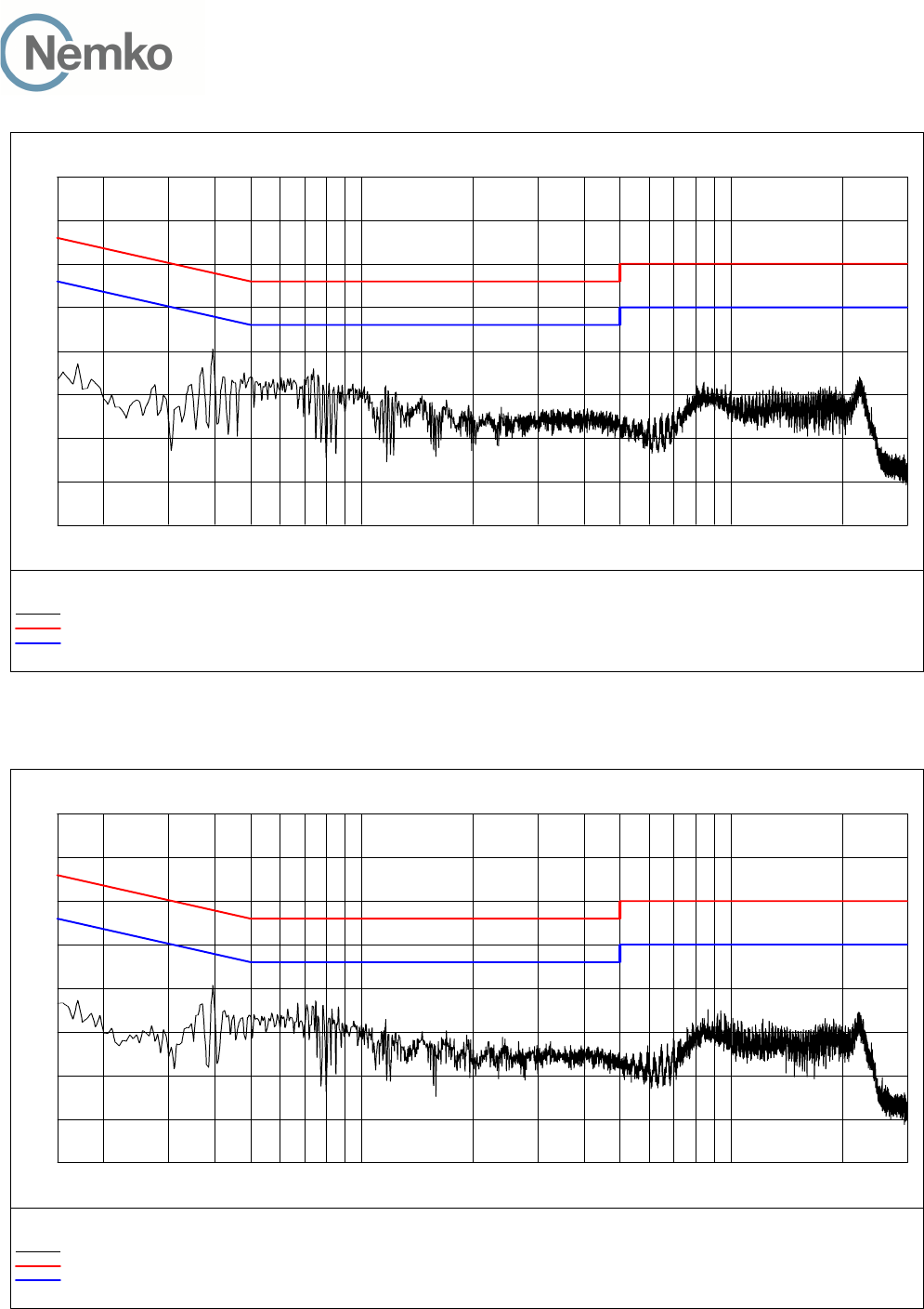
3.1 Power Line Conducted Emissions
Para. No.: 15.207 (a)
Test Performed By: Thanh Tran Date of Test: 13-May-2014
Measurement procedure: ANSI C63.4-2009 using 50 µH/50 ohms LISN.
Test Results: Complies
Measurement Data: See attached graph, (Peak detector).
Highest measured value (L1 and N):
(Plots show maximum of Phase L1 and N)

TEST REPORT
FCC part 15D
Report no.: 258223-5
FCC ID: ACJ96NKX-HNC600
Nemko Norway, Instituttveien 6, Kjeller, Norway Page 8 (48)
Standby Mode with PNLV236 Adaptor, 120V 60Hz:
Frequency Level Af Limit Margin Det Position Verdict
[MHz] [dBuV] [dB] [dBuV] [dB] [Pass/Fail]
0.395000 39.00 10.20 58.00 19.00 QP L1 Pass
0.370000 29.00 10.20 48.50 19.50 AV L1 Pass
0.395000 36.50 10.20 48.00 11.50 AV L1 Pass
0.445000 20.20 10.20 47.00 26.80 AV L1 Pass
0.480000 11.20 10.20 46.30 35.10 AV L1 Pass
0.740000 22.10 10.20 46.00 23.90 AV L1 Pass
0.760000 19.40 10.20 46.00 26.60 AV L1 Pass
0.785000 17.40 10.20 46.00 28.60 AV N Pass
0.815000 19.90 10.20 46.00 26.10 AV N Pass
0.840000 18.90 10.20 46.00 27.10 AV N Pass
0.945000 15.10 10.20 46.00 30.90 AV N Pass
1.155000 17.10 10.20 46.00 28.90 AV N Pass
1.180000 15.00 10.20 46.00 31.00 AV N Pass
1.240000 11.70 10.20 46.00 34.30 AV L1 Pass
1.455000 13.90 10.20 46.00 32.10 AV L1 Pass
22.325000 14.30 11.30 50.00 35.70 AV N Pass
Transmit Mode with PNLV236 Adaptor, 120V 60Hz:
Frequency Level Af Limit Margin Det Position Verdict
[MHz] [dBuV] [dB] [dBuV] [dB] [Pass/Fail]
0.395000 39.20 10.20 58.00 18.80 QP L1 Pass
0.750000 30.30 10.20 56.00 25.70 QP N Pass
0.170000 16.00 10.10 55.00 39.00 AV L1 Pass
0.370000 28.40 10.20 48.50 20.10 AV L1 Pass
0.395000 36.50 10.20 48.00 11.50 AV L1 Pass
0.570000 17.30 10.20 46.00 28.70 AV N Pass
0.750000 9.00 10.20 46.00 37.00 AV N Pass
0.785000 18.00 10.20 46.00 28.00 AV N Pass
0.830000 6.90 10.20 46.00 39.10 AV N Pass
0.865000 17.00 10.20 46.00 29.00 AV N Pass
0.950000 12.00 10.20 46.00 34.00 AV N Pass
1.695000 10.70 10.20 46.00 35.30 AV L1 Pass
1.925000 12.20 10.20 46.00 33.80 AV L1 Pass
8.670000 15.10 10.60 50.00 34.90 AV L1 Pass
12.200000 13.00 10.70 50.00 37.00 AV L1 Pass
18.000000 11.30 11.00 50.00 38.70 AV L1 Pass
22.205000 15.20 11.30 50.00 34.80 AV N Pass
TEST REPORT
FCC part 15D
Report no.: 258223-5
FCC ID: ACJ96NKX-HNC600
Nemko Norway, Instituttveien 6, Kjeller, Norway Page 9 (48)
0
10
20
30
40
50
60
70
80
Level [dBµV]
150k 300k 500k 1M 2M 3M 5M 7M 10M 30M
Frequency [Hz]
+
+
+
+
+
+
+
+
+
++
+
+++
x
x MES 258223N_Qp
+ MES 258223N_Av
MES 258223N
LIM EN 55022 V QP
LIM EN 55022 V AV
Standby Mode with PNLV236 Adaptor, 120V 60Hz
0
10
20
30
40
50
60
70
80
Level [dBµV]
150k 300k 500k 1M 2M 3M 5M 7M 10M 30M
Frequency [Hz]
+
+
+
+
+
+
+
+
++++++
+
x
x
x MES 258223N_Qp
+ MES 258223N_Av
MES 258223N
LIM EN 55022 V QP
LIM EN 55022 V AV
Transmit Mode with PNLV236 Adaptor, 120V 60Hz

TEST REPORT
FCC part 15D
Report no.: 258223-5
FCC ID: ACJ96NKX-HNC600
Nemko Norway, Instituttveien 6, Kjeller, Norway Page 10 (48)
3.2 Coordination with fixed microwave
The affidavit from UTAM, Inc. is included in the documentation supplied by the applicant:
Yes No
Requirement, FCC 15.307 (b):
Each application for certification of equipment operating under the provisions of this Subpart must be
accompanied by an affidavit from UTAM, Inc. certifying that the applicant is a participating member of UTAM,
Inc. In the event a grantee fails to fulfill the obligations attendant to participation in UTAM, Inc., the
Commission may invoke administrative sanctions as necessary to preclude continued marketing and
installation of devices covered by the grant of certification, including but not limited to revoking certification.
3.3 Digital Modulation Techniques
The EUT uses Multi Carrier / Time Division Multiple Access / Time Division Duplex and Digital GFSK
modulation. For further details see the operational description provided by the applicant.
Requirement, FCC 15.319(b):
All transmissions must use only digital modulation techniques.
3.4 Labeling Requirements
See separate documents showing the label design and the placement of the label on the EUT.
Requirements FCC 15.19
The FCC Identifier shall be displayed on the label, and the device(s) shall bear the following statement in a
conspicuous location on the device or in the user manual if the device is too small:
This device complies with Part 15 of the FCC Rules. Operation is subject to the following two conditions: (1)
this device may not cause harmful interference, and (2) this device must accept any interference received,
including interference that may cause undesired operation.
The label itself shall be of a permanent type, not a paper label, and shall last the lifetime of the equipment.

TEST REPORT
FCC part 15D
Report no.: 258223-5
FCC ID: ACJ96NKX-HNC600
Nemko Norway, Instituttveien 6, Kjeller, Norway Page 11 (48)
3.5 Antenna Requirement
Does the EUT have detachable antenna(s)? Yes No
If detachable, is the antenna connector(s) non-standard?
Yes No
The tested equipment has only integral antennas. The conducted tests were performed on a sample with a
temporary antenna connector.
Requirement: FCC 15.203, 15.204, 15.317.
3.6 Channel Frequencies
UPCS CHANNEL FREQUENCY (MHz)
Upper Band Edge 1930.000
0 (Highest) 1928.448
1 1926.720
2 1924.992
3 1923.264
4 (Lowest) 1921.536
Lower Band Edge 1920.000
Requirement: FCC 15.303
Within 1920 -1930 MHz band for isochronous devices.
TEST REPORT
FCC part 15D
Report no.: 258223-5
FCC ID: ACJ96NKX-HNC600
Nemko Norway, Instituttveien 6, Kjeller, Norway Page 12 (48)
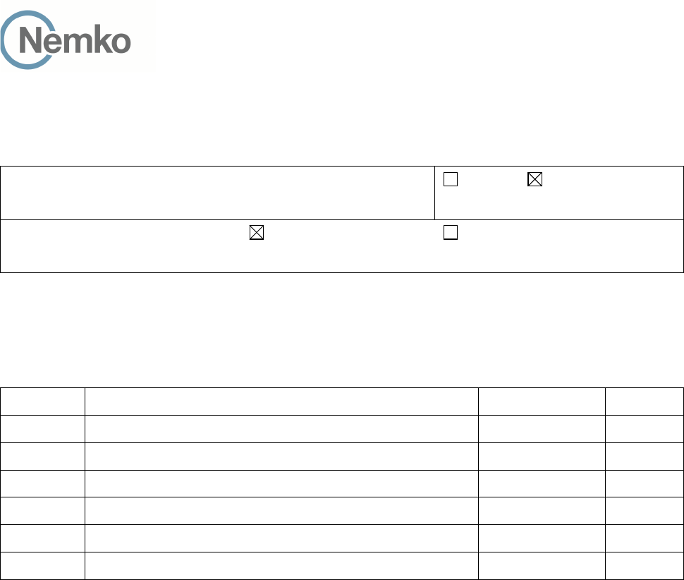
3.7 Automatic Discontinuation of Transmission
Does the EUT transmit Control and Signaling Information? YES NO
TYPE OF EUT : INITIATING DEVICE RESPONDING DEVICE
The following tests simulate the reaction of the EUT in case of either absence of information to transmit or
operational failure after a connection with the companion device is established.
Number Test EUT Reaction Verdict
1 Power removed from EUT C Pass
2 Switch Off EUT N/A Pass
3 Hook-On by EUT N/A Pass
4 Power Removed from Companion Device A Pass
5 Switch Off Companion Device N/A Pass
6 Hook-On by Companion Device N/A Pass
A - Connection breakdown, Cease of all transmissions
B - Connection breakdown, EUT transmits control and signaling information
C - Connection breakdown, Companion Device transmits control and signaling information
N/A - Not Applicable (Neither EUT nor Companion Device have On/Off switch or can perform Hook-On)
Requirements, FCC 15.319(f)
The device shall automatically discontinue transmission in case of either absence of information to transmit
or operational failure. These provisions are not intended to preclude transmission of control and signaling
information or use of repetitive codes used by certain digital technologies to complete frame or burst
intervals.

TEST REPORT
FCC part 15D
Report no.: 258223-5
FCC ID: ACJ96NKX-HNC600
Nemko Norway, Instituttveien 6, Kjeller, Norway Page 13 (48)
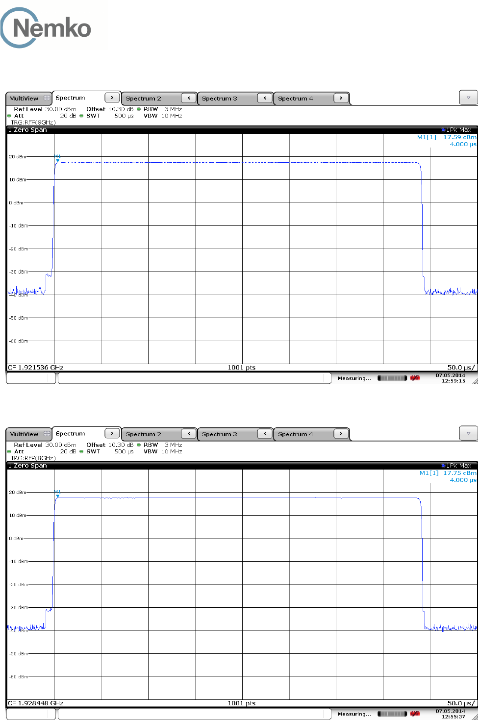
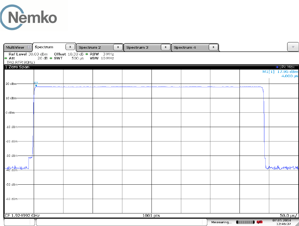
3.8 Peak Power Output
Test Method:
ANSI C63.17, clause 6.1.2.
Test Results: Complies
Measurement Data:
Maximum Conducted Output Power
Channel No. Frequency
(MHz)
Maximum
Conducted
Output Power
(dBm)
Maximum
Antenna
Gain
(dBi)
Maximum
Radiated
Output Power
(dBm)
4 1921.536 17.6 0.0* 17.6
2 1924.992 18.0 0.0* 18.0
0 1928.448 17.8 0.0* 17.8
*Antenna gain value is declared by the manufacturer.
Limit:
Conducted: 100 µW x SQRT(B)
where B is the measured Emission Bandwidth in Hz
FCC 15.319(c)(e): 20.76 dBm (119 mW)
RSS-213, Issue 2: 20.51 dBm (113 mW)
The antenna gain is below 3 dBi, no reduction in transmit power is necessary.
Requirements, FCC 15.319(c)(e), RSS-213, Issue 2
Peak transmit power shall not exceed 100 microwatts multiplied by the square root of the emission bandwidth
in Hertz.
The peak transmit power shall be reduced by the amount in decibels that the maximum directional gain of the
antenna exceeds 3 dBi.
TEST REPORT
FCC part 15D
Report no.: 258223-5
FCC ID: ACJ96NKX-HNC600
Nemko Norway, Instituttveien 6, Kjeller, Norway Page 14 (48)
Conducted Peak Output Power
Lower Channel
Upper Channel
TEST REPORT
FCC part 15D
Report no.: 258223-5
FCC ID: ACJ96NKX-HNC600
Nemko Norway, Instituttveien 6, Kjeller, Norway Page 15 (48)
Middle Channel

TEST REPORT
FCC part 15D
Report no.: 258223-5
FCC ID: ACJ96NKX-HNC600
Nemko Norway, Instituttveien 6, Kjeller, Norway Page 16 (48)
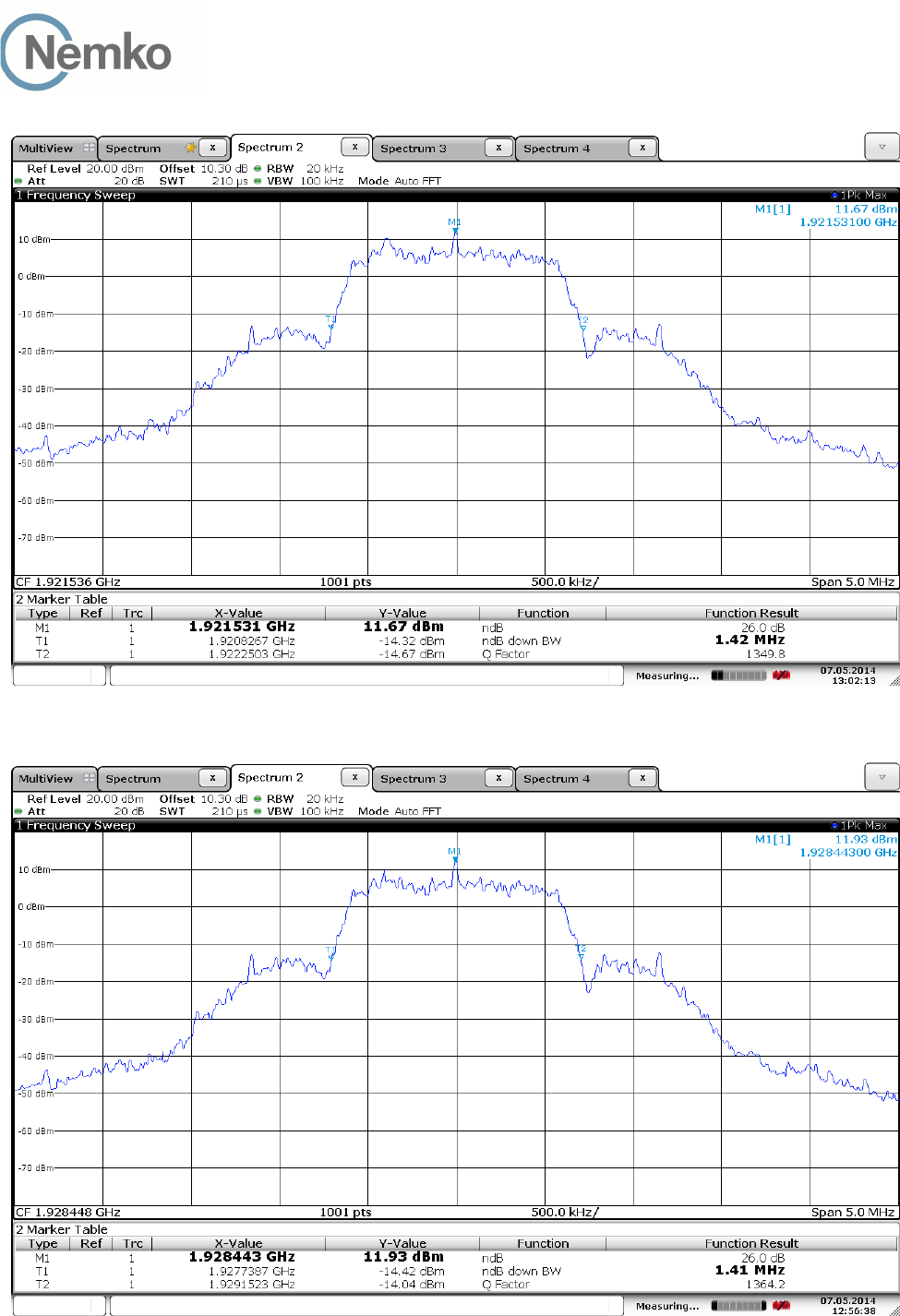
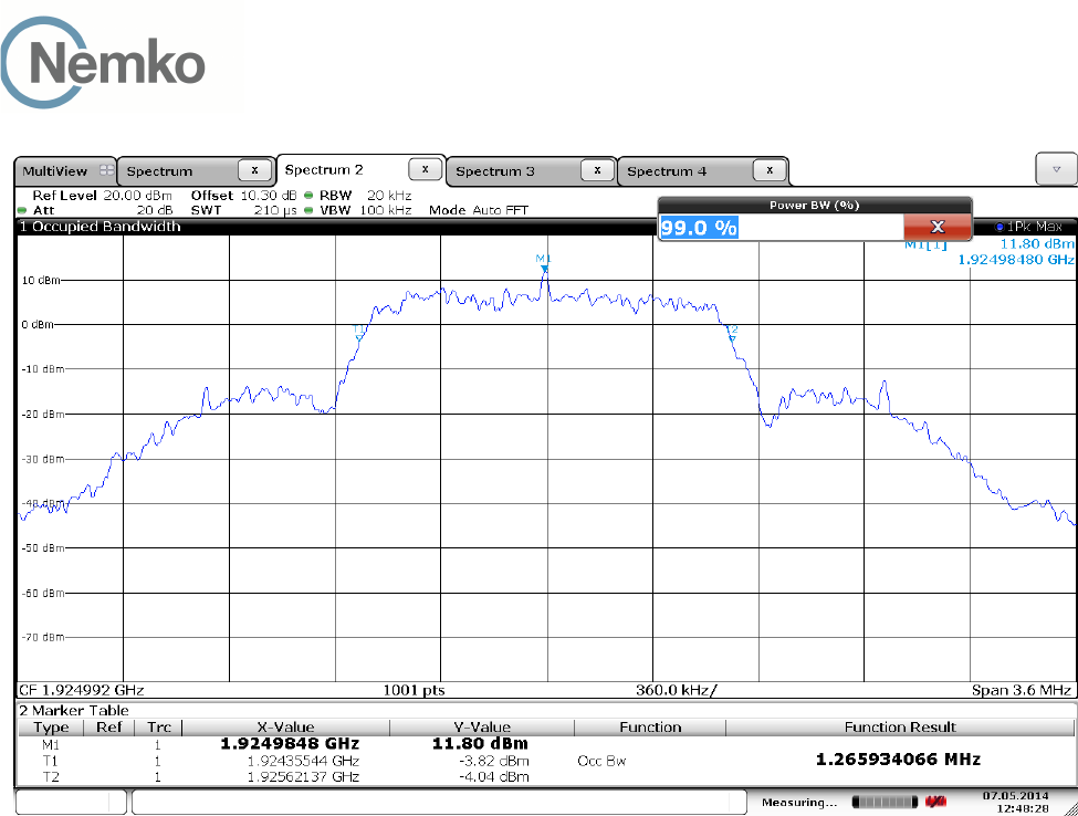
3.9 Emission Bandwidth B
Test Method:
ANSI C63.17, clause 6.1.3.
Test Results: Complies
Measurement Data:
Channel No. Frequency
(MHz)
26 dB Bandwidth B
(kHz)
4 1921.536 1420
0 1928.448 1410
Channel No. Frequency
(MHz)
99% Bandwidth
(kHz)
2 1924.992 1266
Channel No. Frequency
(MHz)
6 dB Bandwidth
(kHz)
4 1921.536 N/A
0 1928.448 N/A
Channel No. Frequency
(MHz)
12 dB Bandwidth
(kHz)
4 1921.536 N/A
0 1928.448 N/A
Requirements, FCC 15.323(a)
The 26 dB Bandwidth B shall be larger than 50 kHz and less than 2.5 MHz.
Requirements, RSS-213 Issue 2, clause 6.4
The 99% Bandwidth shall be larger than 50 kHz and less than 2.5 MHz.
No requirements for 6 and 12 dB Bandwidth, these values are only used for testing Monitoring Bandwidth if
the Simple Compliance test fails (ANSI C63.17, clause 7.4).
TEST REPORT
FCC part 15D
Report no.: 258223-5
FCC ID: ACJ96NKX-HNC600
Nemko Norway, Instituttveien 6, Kjeller, Norway Page 17 (48)
Emission Bandwidth B, Lower Channel
Emission Bandwidth B, Upper Channel
TEST REPORT
FCC part 15D
Report no.: 258223-5
FCC ID: ACJ96NKX-HNC600
Nemko Norway, Instituttveien 6, Kjeller, Norway Page 18 (48)
99% Bandwidth, Middle Channel

TEST REPORT
FCC part 15D
Report no.: 258223-5
FCC ID: ACJ96NKX-HNC600
Nemko Norway, Instituttveien 6, Kjeller, Norway Page 19 (48)
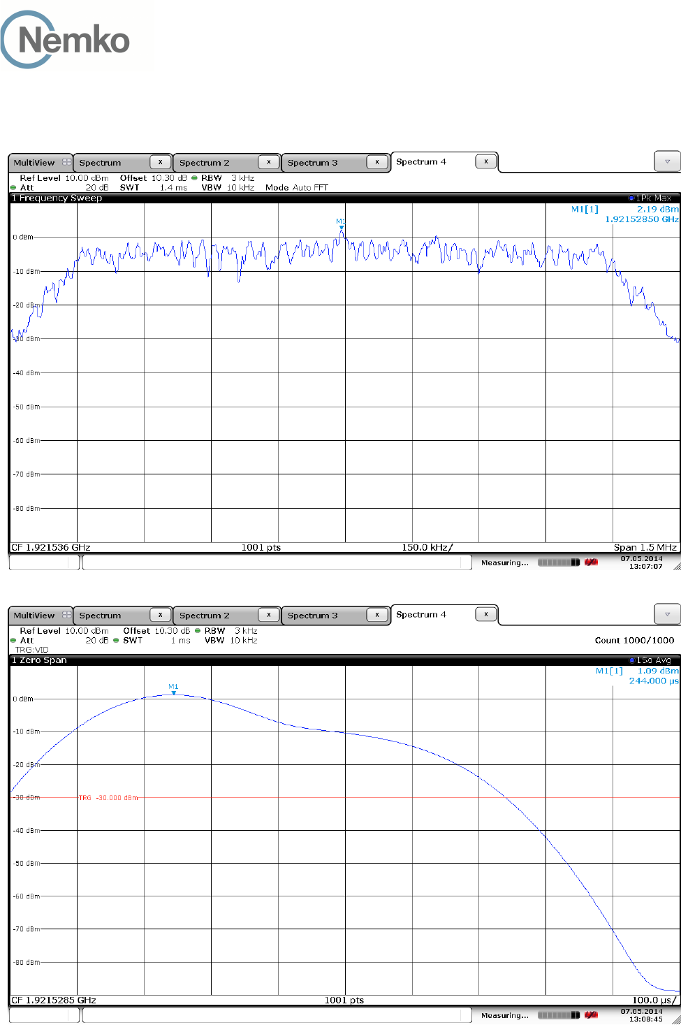
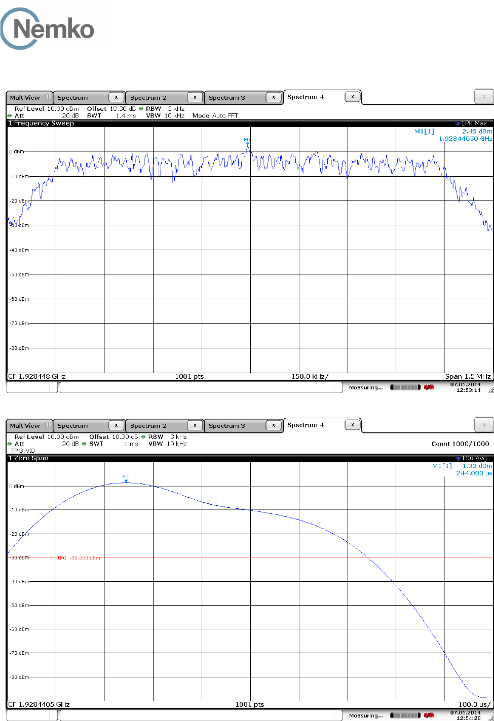
3.10 Power Spectral Density
Test Method:
ANSI C63.17, clause 6.1.5.
Test Results: Complies
Measurement Data:
Channel No. Frequency
(MHz)
Power Spectral Density
(dBm)
4 1921.536 1.1
0 1928.448 1.3
Averaged over 1000 sweeps.
Requirements, FCC 15.319(d)
The Power Spectral Density shall be less than 3 mW (4.77 dBm) when averaged over at least 100 sweeps.
TEST REPORT
FCC part 15D
Report no.: 258223-5
FCC ID: ACJ96NKX-HNC600
Nemko Norway, Instituttveien 6, Kjeller, Norway Page 20 (48)
Power Spectral Density
Lower Channel:
Overview
Averaged, 1000 Sweeps
TEST REPORT
FCC part 15D
Report no.: 258223-5
FCC ID: ACJ96NKX-HNC600
Nemko Norway, Instituttveien 6, Kjeller, Norway Page 21 (48)
Upper Channel:
Overview
Averaged, 1000 Sweeps
TEST REPORT
FCC part 15D
Report no.: 258223-5
FCC ID: ACJ96NKX-HNC600
Nemko Norway, Instituttveien 6, Kjeller, Norway Page 22 (48)
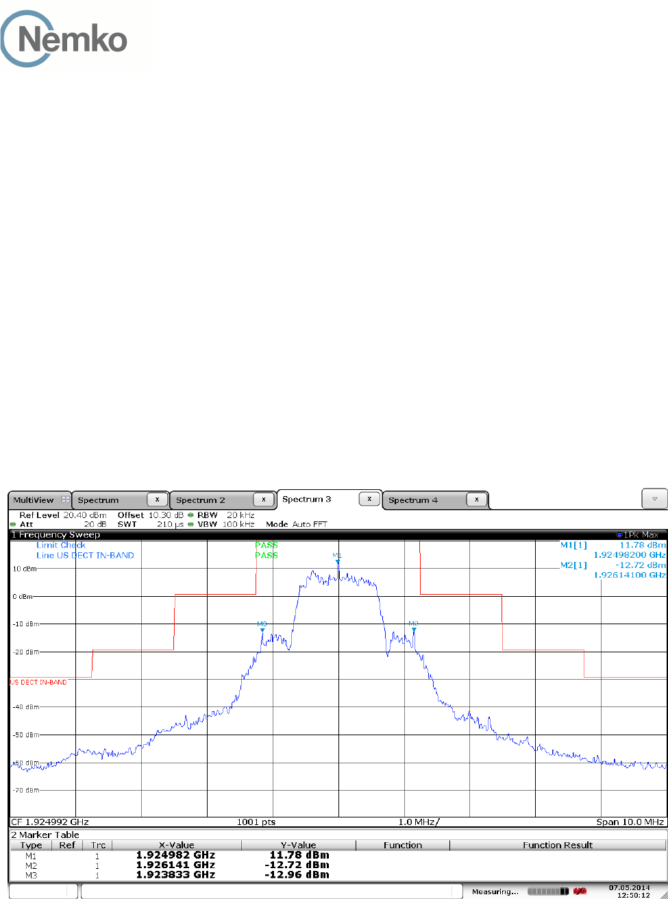
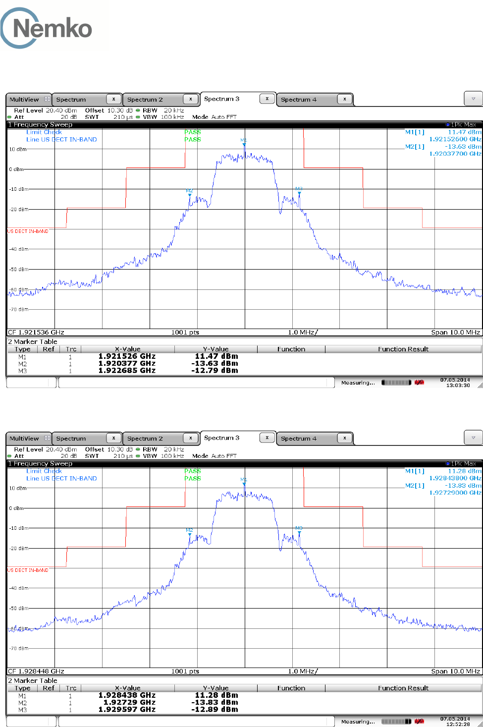
3.11 In-Band Unwanted Emissions, Conducted
Test Method:
ANSI C63.17, clause 6.1.6.1.
Test Results: Complies
Measurement Data:
See plots.
Requirements, FCC 15.323(d):
B < f ≤ 2B : at least 30 dB below max. permitted peak power
2B < f ≤ 3B : at least 50 dB below max. permitted peak power
3B < f ≤ UPCS Band Edge : at least 60 dB below max. permitted peak power
Middle Channel
TEST REPORT
FCC part 15D
Report no.: 258223-5
FCC ID: ACJ96NKX-HNC600
Nemko Norway, Instituttveien 6, Kjeller, Norway Page 23 (48)
In-Band Unwanted Emissions, Conducted
Lower Channel
Upper Channel
TEST REPORT
FCC part 15D
Report no.: 258223-5
FCC ID: ACJ96NKX-HNC600
Nemko Norway, Instituttveien 6, Kjeller, Norway Page 24 (48)
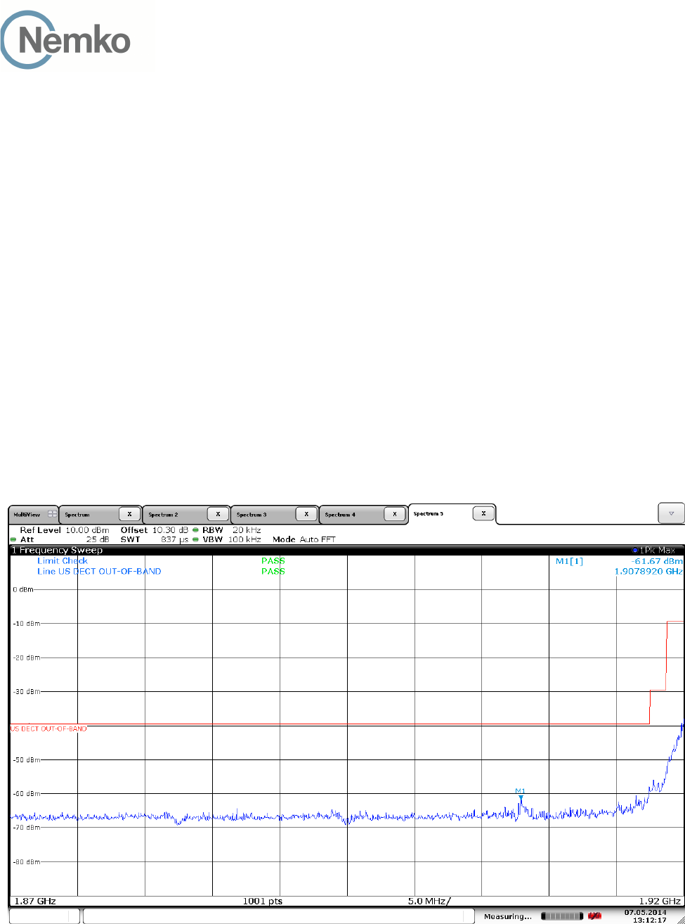
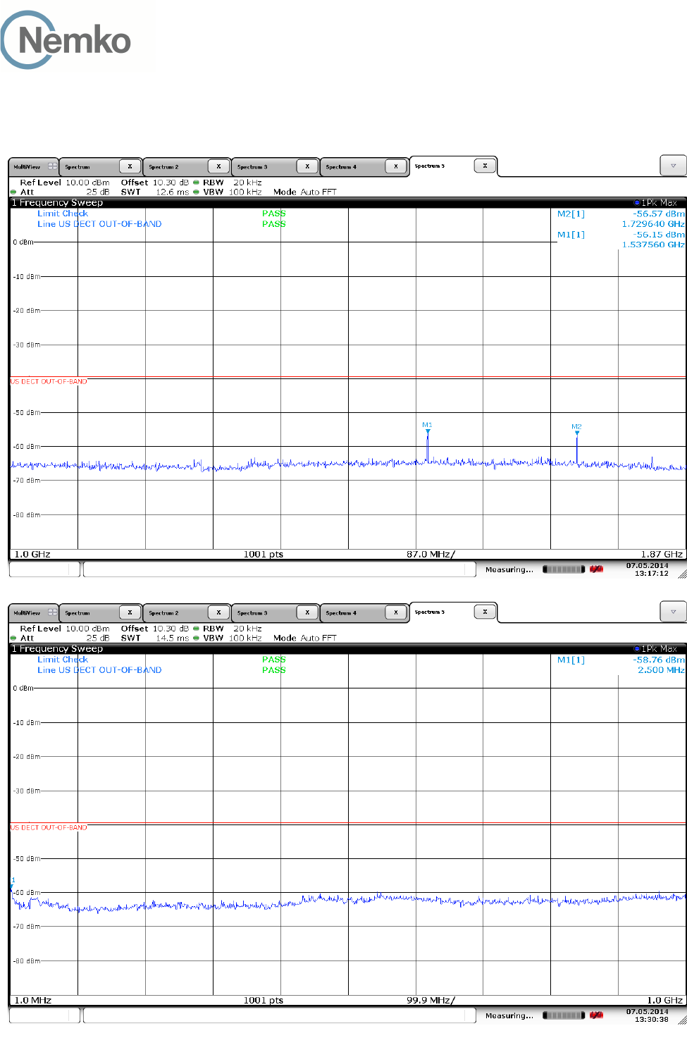
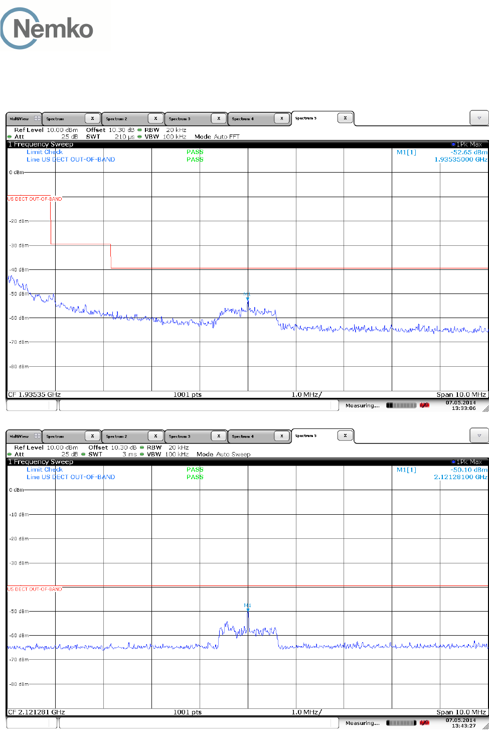
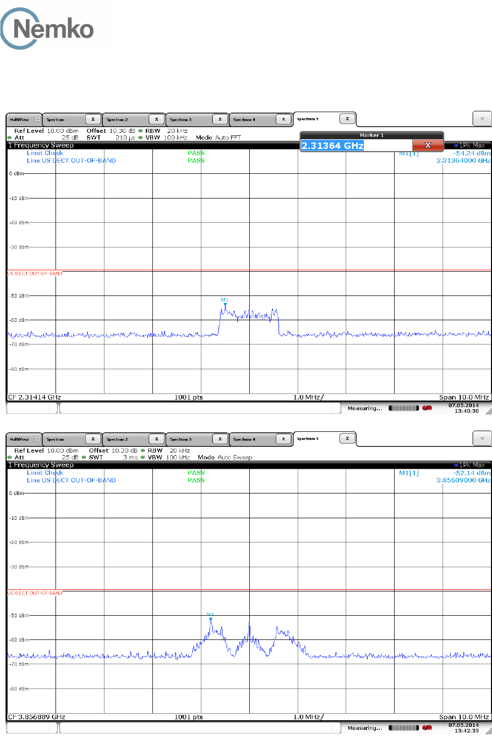
3.12 Out-of-band Emissions, Conducted
Test Method:
ANSI C63.17, clause 6.1.6.2.
Test Results: Complies
Measurement Data:
See plots.
Requirements, FCC 15.323(d):
f ≤ 1.25MHz outside UPCS band : ≤ -9.5dBm
1.25MHz ≤ f ≤ 2.5MHz outside UPCS band : ≤ -29.5 dBm
f ≥ 2.5MHz outside UPCS band : ≤ -39.5 dBm
Lower Channel:
TEST REPORT
FCC part 15D
Report no.: 258223-5
FCC ID: ACJ96NKX-HNC600
Nemko Norway, Instituttveien 6, Kjeller, Norway Page 25 (48)
Out-of-Band Emissions, Conducted
Lower Channel:
TEST REPORT
FCC part 15D
Report no.: 258223-5
FCC ID: ACJ96NKX-HNC600
Nemko Norway, Instituttveien 6, Kjeller, Norway Page 26 (48)
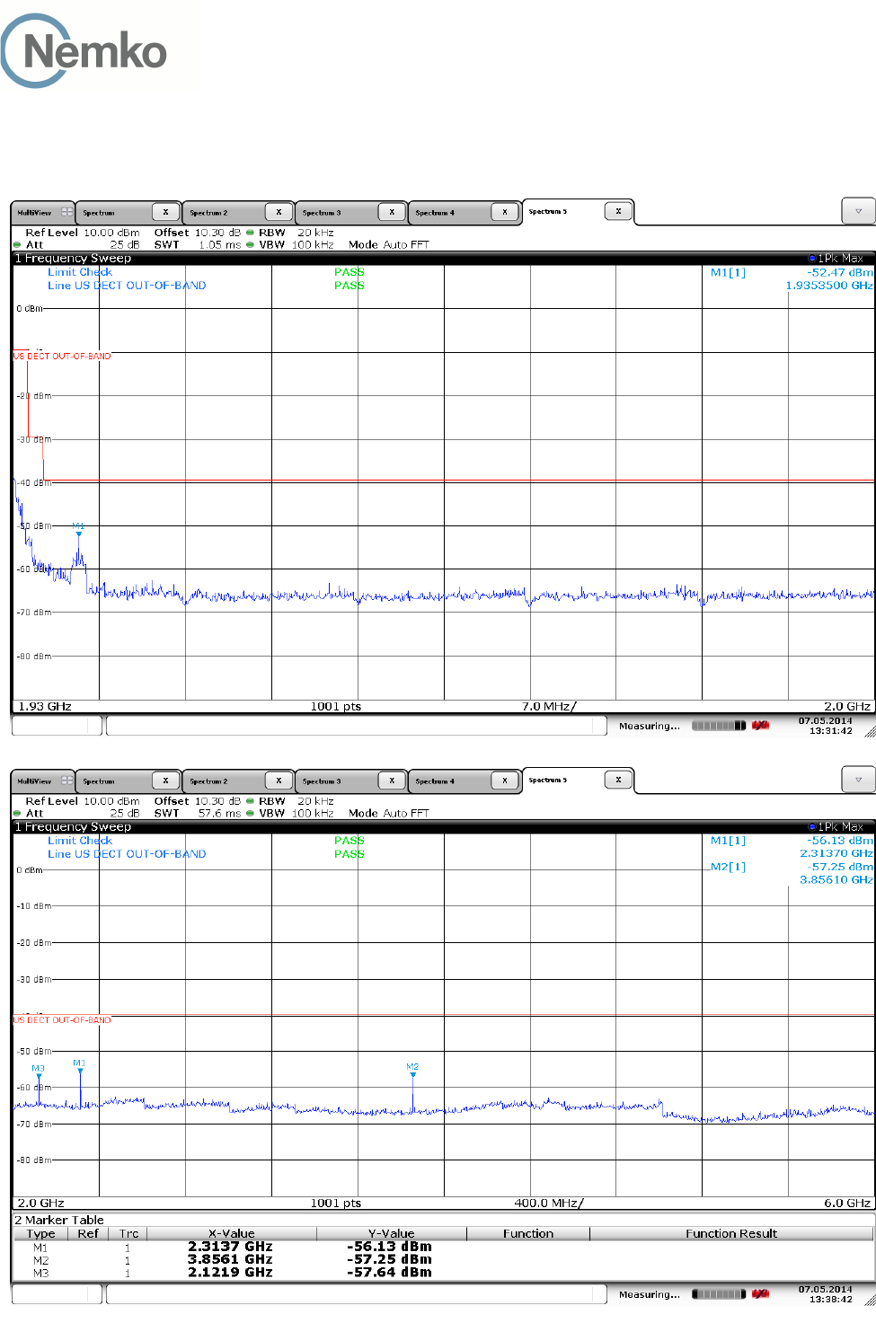
Out-of-Band Emissions, Conducted
Upper Channel:
TEST REPORT
FCC part 15D
Report no.: 258223-5
FCC ID: ACJ96NKX-HNC600
Nemko Norway, Instituttveien 6, Kjeller, Norway Page 27 (48)
Out-of-Band Emissions, Conducted
Upper Channel:
TEST REPORT
FCC part 15D
Report no.: 258223-5
FCC ID: ACJ96NKX-HNC600
Nemko Norway, Instituttveien 6, Kjeller, Norway Page 28 (48)
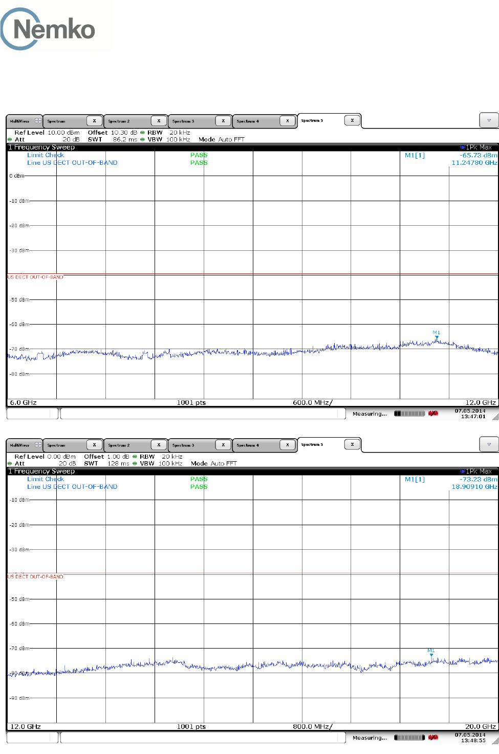
Out-of-Band Emissions, Conducted
Upper Channel:
TEST REPORT
FCC part 15D
Report no.: 258223-5
FCC ID: ACJ96NKX-HNC600
Nemko Norway, Instituttveien 6, Kjeller, Norway Page 29 (48)
Out-of-Band Emissions, Conducted
Upper Channel:

TEST REPORT
FCC part 15D
Report no.: 258223-5
FCC ID: ACJ96NKX-HNC600
Nemko Norway, Instituttveien 6, Kjeller, Norway Page 30 (48)
3.13 Carrier Frequency Stability
Test Method:
ANSI C63.17, clause 6.2.1.
Test Results: Complies
Measurement Data:
The Frequency Stability is measured with a R&S CMD60 DECT Tester. The CMD60 was logged by a
computer programmed to get new readings as fast as possible (about 3 readings per second) over the noted
time period or number of readings. The peak-to-peak difference was recorded and the mean value and
deviation in ppm was calculated.
The Carrier Frequency Stability over Power Supply Voltage and over Temperature is measured with a
Frequency Domain Analyzer in histogram mode.
Carrier Frequency Stability over Time at Nominal Temperature
Average Mean Carrier
Frequency (MHz)
Max. Diff.
(kHz)
Min. Diff.
(kHz)
Max. Dev.
(ppm)
Limit
1926.726782 7.793 5.690 0.5 ±10 ppm
Deviation ppm = ((Diff.) / Mean Carrier Freq.) x 10
6
Deviation (ppm) is calculated from 3000 readings.
Frequency Stability over Power Supply Voltage at Nominal Temperature
Voltage Measured Carrier
Frequency (MHz)
Difference
(kHz)
Deviation
(ppm)
Limit
V
nom
1924.979167 / /
85% of V
nom
1924.976549 -1.1 -0.6 ±10 ppm
115% of V
nom
1924.977240 -1.6 -0.8
Deviation ppm = ((Mean – Measured Frequency) / Mean) x 10
6
Frequency Stability over Temperature
Temperature Measured Carrier
Frequency (MHz)
Difference
(kHz)
Deviation
(ppm)
Limit
T =
+20 °C 1924.979167 0 0
T = -20 °C 1924.978079 -2.6 -1.4 ±10 ppm
T = +50 °C 1924.977585 -1.9 -1.0
Deviation ppm = ((Mean – Measured Frequency) / Mean) x 10
6

TEST REPORT
FCC part 15D
Report no.: 258223-5
FCC ID: ACJ96NKX-HNC600
Nemko Norway, Instituttveien 6, Kjeller, Norway Page 31 (48)
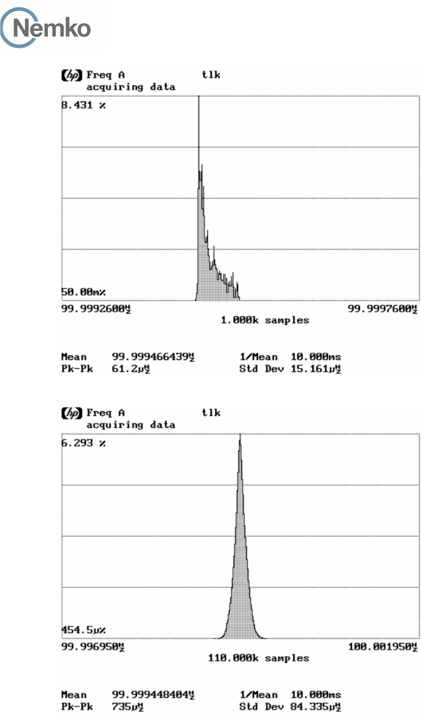
3.14 Frame Repetition Stability
Test Method:
ANSI C63.17, clause 6.2.2.
Test Results: Complies
Measurement Data:
The envelope of the RF signal from the EUT is detected with a Crystal Detector and the mean and standard
deviation of the frame repetition frequency is then gated over 100 frames and measured with a Frequency
Domain Analyzer. The frame repetition stability is 3 times the standard deviation.
Carrier Frequency
(MHz)
Mean
(Hz)
Standard Deviation
(Hz)
Frame Repetition
Stability (ppm)
1924.992 99.999466 0.000015 0.455
Limit:
Frame Repetition Stability ±10 ppm (TDMA)
Ref. FCC 15.323(e), ANSI C63.17, clause 6.2.2
3.15 Frame Period and Jitter
Test Method:
ANSI C63.17, clause 6.2.3.
Test Results: Complies
Measurement Data:
Carrier Frequency
(MHz)
Frame Period
(ms)
Max Jitter
(µs)
3xStandard Deviation
of Jitter (µs)
1924.992 99.999 -0.037 -0.025
Max Jitter = (1/ (Frame period + Pk-Pk/2)) - (1/Frame Period), when Pk-Pk and Frame Period are in Hz
3xSt.Dev.Jitter = 3x (1/(Frame Period + St.Dev) – 1/St.Dev) x 10
6
Limit:
Frame Period 20 or 10 ms
Max Jitter 25 µs
3 times St.Dev of Jitter 12.5 µs
Ref. FCC 15.323(e), ANSI C63.17, clause 6.2.3
TEST REPORT
FCC part 15D
Report no.: 258223-5
FCC ID: ACJ96NKX-HNC600
Nemko Norway, Instituttveien 6, Kjeller, Norway Page 32 (48)
Frame Repetition Stability, Gated over 100 Frames
Frame Period and Jitter
TEST REPORT
FCC part 15D
Report no.: 258223-5
FCC ID: ACJ96NKX-HNC600
Nemko Norway, Instituttveien 6, Kjeller, Norway Page 33 (48)
3.16 Monitoring Threshold, Least Interfered Channel
Monitoring Threshold Limits:
Lower Threshold:
T
L
= 15 log
B - 184 + 30 - P
EUT
(dBm)
Upper Threshold:
T
U
= 15 log
B - 184 + 50 - P
EUT
(dBm)
B is measured Emission Bandwidth in Hz
P
EUT
is measured Transmitter Power in dBm
Calculated values:
FCC 15.323 RSS-213, Issue 2
Lower Threshold -79.7 dBm -80.4 dBm
Upper Threshold N/A -60.4 dBm
Least Interfered Channel Procedure (LIC) may only be used by systems with more than 20 duplex system
access channels. Systems with less than 20 duplex system access channels are not allowed to transmit
when interferer level is above Lower Threshold.
Upper Threshold has been removed from FCC 15D but still exists in the current Industry Canada RSS-213.
Measurement Procedure:
The Upper or Lower Threshold is found by the procedure defined in ANSI C63.17 clause 7.3.1 or 7.3.2.
Least Interfered Channel Procedure NOT used:
Lower Threshold N/A
dBm
Least Interfered Channel Procedure:
Upper Threshold -63.0
dBm
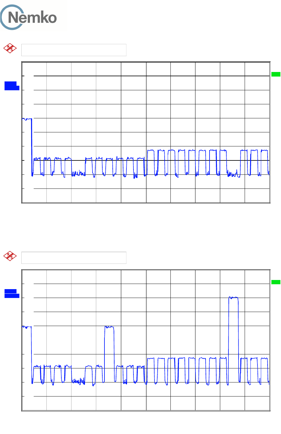
Least Interfered Channel (LIC) Procedure Test, FCC 15.323(b), (c)(2) and (c)(5)
ANSI C63.17 clause 7.3.3 ref. Observation Verdict
b) f
1
T
L
+ 13 dB, f
2
at T
L
+ 6 dB Transmission always on f
2
Pass
c) f
1
T
L
+ 6 dB, f
2
at T
L
+ 13 dB Transmission always on f
1
Pass
d) f
1
T
L
+ 7 dB, f
2
at T
L
Transmission always on f
2
Pass
e) f
1
T
L
, f
2
at T
L
+ 7 dB Transmission always on f
1
Pass
TEST REPORT
FCC part 15D
Report no.: 258223-5
FCC ID: ACJ96NKX-HNC600
Nemko Norway, Instituttveien 6, Kjeller, Norway Page 34 (48)
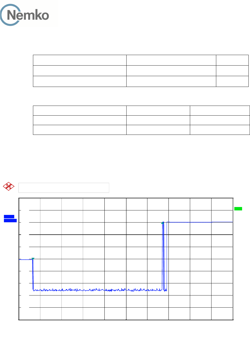
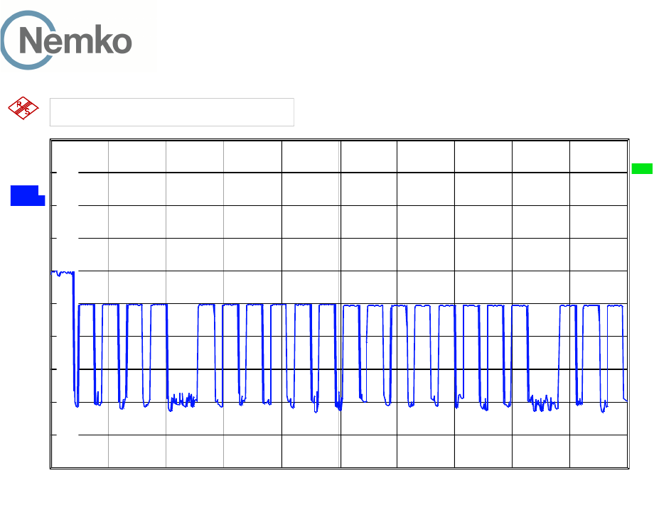
Selected Channel Confirmation, FCC 15.323(c)(1) and (5)
ANSI C63.17 clause 7.3.4 Observation Verdict
b) Shall not transmit on f
1
EUT transmits on f
2
Pass
d) Shall not transmit on f
2
EUT transmits on f
1
Pass
Limits:
FCC 15.323 RSS-213, Issue 2
Lower Threshold + 6 dB margin -73.7 dBm -74.4 dBm
Upper Threshold + 6 dB margin N/A -54.4 dBm
Ref 0 dBm
3.03 s
Att 10 dB
3.03 s
*
3.03 s
CLRW
R
3.03 s
A
3.03 s
SGL
3.03 s
RBW 300 kHz
3.03 s VBW 1 MHz 3.03 s
SWT 5 s
3.03 s
Center 1.923264 GHz
3.03 s
500 ms/
3.03 s
TRG
3.03 s
*
3.03 s
1 PK
3.03 s 3.03 s 3.03 s 3.03 s 3.03 s 3.03 s 3.03 s 3.03 s 3.03 s 3.03 s
-100
-90
-80
-70
-60
-50
-40
-30
-20
-10
0
3.03 s
1
Marker 1 [T1 ]
-50.58 dB
m
329.924000 ms
2
Delta 2 [T1 ]
30.77 dB
3.030000 s
DELTA MARKER 2
3.03 s
Date: 12.MAY.2014 14:33:00
7.3.4 Selected Channel Confirmation, Connection 3.0s After Interferer Removed

TEST REPORT
FCC part 15D
Report no.: 258223-5
FCC ID: ACJ96NKX-HNC600
Nemko Norway, Instituttveien 6, Kjeller, Norway Page 35 (48)
3.17 Threshold Monitoring Bandwidth
This test is only required if a dedicated monitoring receiver is used. However, if the test is not carried out the
manufacturer shall declare and provide proper evidence that the monitoring is made through the radio
receiver used for communication.
Measurement Procedure:
Simple Compliance Test, ANSI C63.17, clause 7.4.1
More Detailed Test, ANSI C63.17, clause 7.4.2
The test is passed if either the Simple Compliance Test or the More Detailed test is passed.
During this test the spectrum analyzer is observed visually to see if the EUT transmits or not.
Test Results:
Test performed Observation Verdict
Simple Compliance test, at ±30% of B No transmissions Pass
More Detailed Test, at -6 dB points N/A N/A
More Detailed Test, at -12 dB points N/A N/A
The more detailed test must be pass at both the -6 and -12 dB points if the Simple Compliance test fails.
Comment: The Simple Compliance Test was performed with the level at T
U
+ U
M
+ 10 dB to check that the
EUT did not transmit at all.
The tested EUT uses the same receiver for monitoring and communication, this test is therefore
not required. However the test has been performed nonetheless and the test is passed.
Limits, FCC 15.323(c)(7):
The monitoring system bandwidth must be equal to or greater than the emission bandwidth of the intended
transmission.

TEST REPORT
FCC part 15D
Report no.: 258223-5
FCC ID: ACJ96NKX-HNC600
Nemko Norway, Instituttveien 6, Kjeller, Norway Page 36 (48)
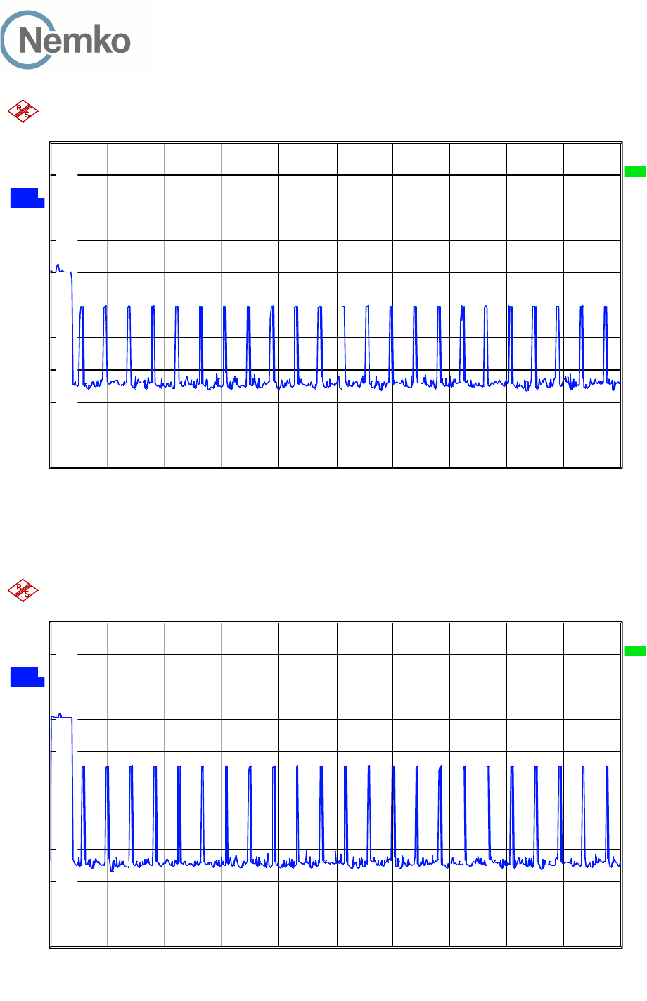
3.18 Reaction Time and Monitoring Interval
Measurement Procedure
ANSI C63.17, clause 7.5
Test results:
By administrative commands and out-of-operating region interference, the EUT is restricted to operate on a
single carrier frequency.
Time-synchronized pulsed interference was then applied on the carrier at pulsed levels T
U
+ U
M
to check that
the EUT does not transmit at all. The level was raised 6 dB for part d) with 35 µs pulses.
The pulses are synchronized with the EUT timeslots and applied centered within all timeslots.
Pulse Width, ref. to ANSI C63.17 clause 7.5 Observation Verdict
c) > largest of 50 µs and 50*SQRT(1.25/B) No transmissions Pass
d) > largest of 35 µs and 35*SQRT(1.25/B),
and with interference level raised 6 dB
No transmissions Pass
Comment: Since B is larger than 1.25 MHz the test was performed with pulse lengths of 50 µs and 35 µs.
Limits, FCC 15.323(c)(1), (5) and (7)
The maximum reaction time must be less than 50xSQRT (1.25/emission bandwidth in MHz) microseconds
for signals at the applicable threshold level but shall not be required to be less than 50 microseconds.
If a signal is detected that is 6 dB or more above the applicable threshold level, the maximum reaction time
shall be 35xSQRT (1.25/emission bandwidth in MHz) microseconds but shall not be required to be less than
35 microseconds.
TEST REPORT
FCC part 15D
Report no.: 258223-5
FCC ID: ACJ96NKX-HNC600
Nemko Norway, Instituttveien 6, Kjeller, Norway Page 37 (48)
Ref 0 dBm Att 10 dB
*
CLRW
R
A
TRG
Center 1.923264 GHz 1 ms/
*1 PK
RBW 1 MHz
VBW 3 MHz
SWT 10 ms
-100
-90
-80
-70
-60
-50
-40
-30
-20
-10
0
Date: 12.MAY.2014 14:26:59
50 µs Pulses
Ref 0 dBm Att 10 dB
*
CLRW
R
A
TRG
Center 1.923264 GHz 1 ms/
*1 PK
RBW 1 MHz
VBW 3 MHz
SWT 10 ms
-100
-90
-80
-70
-60
-50
-40
-30
-20
-10
0
Date: 12.MAY.2014 14:27:36
35 µs Pulses

TEST REPORT
FCC part 15D
Report no.: 258223-5
FCC ID: ACJ96NKX-HNC600
Nemko Norway, Instituttveien 6, Kjeller, Norway Page 38 (48)
3.19 Time and Spectrum Window Access Procedure
This requirement is only for EUTs which transmit unacknowledged control and signaling information.
Measurement Procedure:
Timing for EUTs using control and signaling channel type transmissions: ANSI C63.17, clause 8.1
Test results:
Access Criteria, ref. to ANSI C63.17 clause 8.1.1 Observation Verdict
b) Check that the EUT transmits on the interference
free time-slot
N/A N/A
b) The EUT must terminate or pause in its repetitive
transmission of the control and signalling channel on
the open channel to repeat the access criteria not less
frequently than every 30 s
N/A N/A
If FCC 15.323(c)(6) option, If Random Waiting Interval is NOT implemented
Access Criteria, ref. to ANSI C63.17 clause 8.1.2 Observation Verdict
b) Check that the EUT changes to an interference-free
slot when interference is introduced on the time slot in use
N/A N/A
If FCC 15.323(c)(6) option, Only if Random Waiting Interval is implemented
Access Criteria, ref. to ANSI C63.17 clause 8.1.3 Observation Verdict
b-d) Check that the EUT uses random waiting interval
before continuing transmission on an interfered time slot
N/A N/A
Comment: The tested EUT does not transmit unacknowledged control and signaling information.
Limits:
FCC 15.323(c)(4):
Once access to specific combined time and spectrum windows is obtained an acknowledgement from a
system participant must be received by the initiating transmitter within one second or transmission must
cease. Periodic acknowledgements must be received at least every 30 seconds or transmission must cease.
Channels used exclusively for control and signaling information may transmit continuously for 30 seconds
without receiving an acknowledgement, at which time the access criteria must be repeated.
FCC 15.323(c)(6):
If the selected combined time and spectrum windows are unavailable, the device may either monitor and
select different windows or seek to use the same windows after waiting an amount of time, randomly chosen
from a uniform random distribution between 10 and 150 milliseconds, commencing when the channel
becomes available

TEST REPORT
FCC part 15D
Report no.: 258223-5
FCC ID: ACJ96NKX-HNC600
Nemko Norway, Instituttveien 6, Kjeller, Norway Page 39 (48)
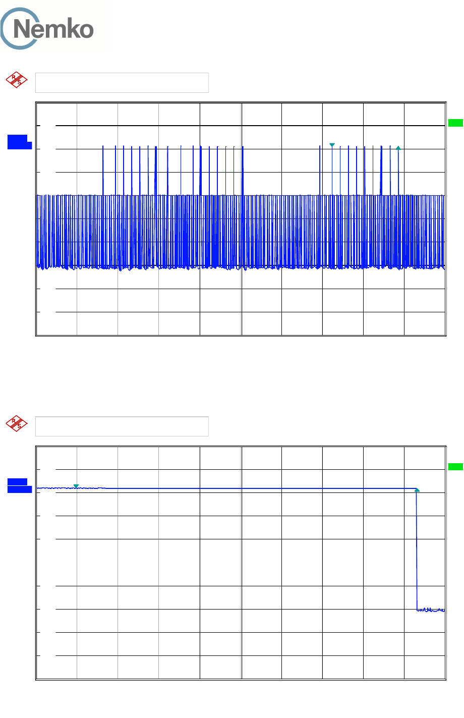
3.20 Acknowledgements and Transmission Duration
Measurement Procedure:
Acknowledgements: ANSI C63.17, clause 8.2.1
Transmission Duration: ANSI C63.17, clause 8.2.2
During the test Initial transmission without acknowledgements the signal from the EUT to the companion
device is blocked by circulators in addition to the tunable attenuator.
The test Transmission time after loss of acknowledgements is performed by cutting-off the signal from
the companion device by a RF switch and measuring the time until the EUT stops transmitting.
The Transmission Duration test is performed by monitoring the slot in use and measuring the time until the
EUT changes to a different slot.
Test Results:
Acknowledgements
Test ref. to ANSI C63.17 clause 8.2.1 Observation Verdict
a) Initial transmission without acknowledgements 0.32 sec Pass
c) Transmission time after loss of acknowledgements 10.0 sec Pass
Transmission Duration
Test ref. to ANSI C63.17 clause 8.2.2 Observation Verdict
b) Transmission duration on same time
and frequency window
2 minutes* Pass
Comment: *EUT stops transmitting after 2 minutes.
Limits, FCC 15.323(c)(3) and (4)
Occupation of the same combined time and spectrum windows by a device or group of cooperating devices
continuously over a period of time longer than 8 hours is not permitted without repeating the access criteria.
Once access to specific combined time and spectrum windows is obtained an acknowledgement from a
system participant must be received by the initiating transmitter within one second or transmission must
cease.
Periodic acknowledgements must be received at least every 30 seconds or transmission must cease.
Channels used exclusively for control and signaling information may transmit continuously for 30 seconds
without receiving an acknowledgement, at which time the access criteria must be repeated.
TEST REPORT
FCC part 15D
Report no.: 258223-5
FCC ID: ACJ96NKX-HNC600
Nemko Norway, Instituttveien 6, Kjeller, Norway Page 40 (48)
Ref 0 dBm
324 ms
Att 10 dB
324 ms
*
324 ms
CLRW
R
324 ms
A
324 ms
TRG
324 ms
RBW 1 MHz
324 ms VBW 3 MHz 324 ms 324 ms 324 ms 324 ms 324 ms 324 ms 324 ms 324 ms 324 ms 324 ms
Center 1.923264 GHz
324 ms
200 ms/
324 ms
SWT 2 s
324 ms
SGL
324 ms
*
324 ms
1 PK
324 ms
-100
-90
-80
-70
-60
-50
-40
-30
-20
-10
0
324 ms
1
Marker 1 [T1 ]
-18.93 dB
m
1.447924 s
2
Delta 2 [T1 ]
-0.00 dB
324.000000 ms
DELTA MARKER 2
324 ms
Date: 12.MAY.2014 14:05:34
8.2.1a) Initial Transmission Without Acknowledgements
Ref 0 dBm
9.992 s
Att 10 dB
9.992 s
*
9.992 s
CLRW
R
9.992 s
A
9.992 s
TRG
9.992 s
RBW 1 MHz
9.992 s VBW 3 MHz 9.992 s 9.992 s 9.992 s 9.992 s 9.992 s 9.992 s 9.992 s 9.992 s 9.992 s 9.992 s
Center 1.923264 GHz
9.992 s
1.2 s/
9.992 s
SWT 12 s
9.992 s
SGL
9.992 s
*
9.992 s
1 PK
9.992 s
-100
-90
-80
-70
-60
-50
-40
-30
-20
-10
0
9.992 s
1
Marker 1 [T1 ]
-18.07 dB
m
1.179924 s
2
Delta 2 [T1 ]
-0.21 dB
9.992000 s
DELTA MARKER 2
9.992 s
Date: 12.MAY.2014 13:43:01
8.2.1c) Transmission Time After Loss of Acknowledgements

TEST REPORT
FCC part 15D
Report no.: 258223-5
FCC ID: ACJ96NKX-HNC600
Nemko Norway, Instituttveien 6, Kjeller, Norway Page 41 (48)
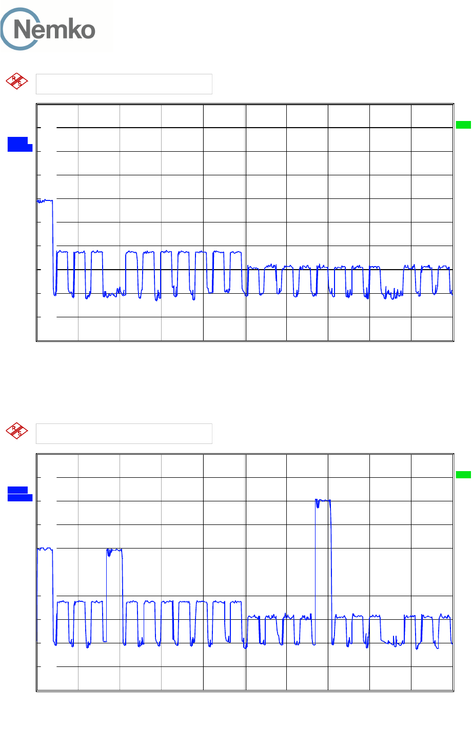
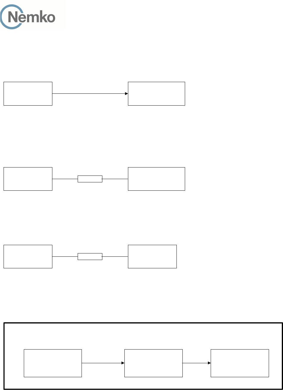
3.21 Dual Access Criteria Check
Measurement Procedure:
EUTs that does not implement the Upper Threshold: ANSI C63.17, clause 8.3.1
EUTs that implement the Upper Threshold: ANSI C63.17, clause 8.3.2
This test is required for equipment that uses the access criteria in FCC 15.323(c)(10).
Test Results:
EUTs that Implements the Upper Threshold:
Test ref. to ANSI C63.17 clause 8.3.2 Observation Verdict
b) EUT is restricted to a single carrier f
1
for TDMA
systems. The Test is Pass if EUT can transmit
EUT can transmit Pass
c) d) Transmission on interference-free receive
time/spectrum window
EUT transmits on interference
free receive slot
Pass
e) f) Transmission on interference-free transmit
time/spectrum window
EUT transmits on interference
free transmit slot
Pass
g) Transmission not possible on any
time/spectrum window
No connection possible Pass
Comment: See plots.
Limits, FCC 15.323(c)(10)
An initiating device may attempt to establish a duplex connection by monitoring both its intended transmit and
receive time and spectrum windows. If both the intended transmit and receive time and spectrum windows
meet the access criteria, then the initiating device can initiate a transmission in the intended transmit time and
spectrum window. If the power detected by the responding device can be decoded as a duplex connection
signal from the initiating device, then the responding device may immediately begin transmitting on the
receive time and spectrum window monitored by the initiating device.
TEST REPORT
FCC part 15D
Report no.: 258223-5
FCC ID: ACJ96NKX-HNC600
Nemko Norway, Instituttveien 6, Kjeller, Norway Page 42 (48)
Ref 0 dBm
300 kHz
Att 10 dB
300 kHz
*
300 kHz
CLRW
R
300 kHz
A
300 kHz
TRG
300 kHz
Center 1.923264 GHz
300 kHz
1 ms/
300 kHz
*
300 kHz
1 PK
300 kHz
RBW 300 kHz
300 kHz VBW 1 MHz 300 kHz
SWT 10 ms
300 kHz
-100
-90
-80
-70
-60
-50
-40
-30
-20
-10
0
300 kHz
RESOLUTION BANDWIDTH
300 kHz
Date: 12.MAY.2014 14:09:13
8.3.2c) EUT Transmits on Interference Free RECEIVE Slot, BEFORE
Ref 0 dBm
300 kHz
Att 10 dB
300 kHz
*
300 kHz
CLRW
R
300 kHz
A
300 kHz
TRG
300 kHz
Center 1.923264 GHz
300 kHz
1 ms/
300 kHz
*
300 kHz
1 PK
300 kHz
RBW 300 kHz
300 kHz VBW 1 MHz 300 kHz
SWT 10 ms
300 kHz
-100
-90
-80
-70
-60
-50
-40
-30
-20
-10
0
300 kHz
RESOLUTION BANDWIDTH
300 kHz
Date: 12.MAY.2014 14:10:22
8.3.2c) EUT Transmits on Interference Free RECEIVE Slot, AFTER
TEST REPORT
FCC part 15D
Report no.: 258223-5
FCC ID: ACJ96NKX-HNC600
Nemko Norway, Instituttveien 6, Kjeller, Norway Page 43 (48)
Ref 0 dBm
300 kHz
Att 10 dB
300 kHz
*
300 kHz
CLRW
R
300 kHz
A
300 kHz
TRG
300 kHz
Center 1.923264 GHz
300 kHz
1 ms/
300 kHz
*
300 kHz
1 PK
300 kHz
RBW 300 kHz
300 kHz VBW 1 MHz 300 kHz
SWT 10 ms
300 kHz
-100
-90
-80
-70
-60
-50
-40
-30
-20
-10
0
300 kHz
RESOLUTION BANDWIDTH
300 kHz
Date: 12.MAY.2014 14:12:33
8.3.2e) EUT Transmits on Interference Free TRANSMIT Slot, BEFORE
Ref 0 dBm
300 kHz
Att 10 dB
300 kHz
*
300 kHz
CLRW
R
300 kHz
A
300 kHz
TRG
300 kHz
Center 1.923264 GHz
300 kHz
1 ms/
300 kHz
*
300 kHz
1 PK
300 kHz
RBW 300 kHz
300 kHz VBW 1 MHz 300 kHz
SWT 10 ms
300 kHz
-100
-90
-80
-70
-60
-50
-40
-30
-20
-10
0
300 kHz
RESOLUTION BANDWIDTH
300 kHz
Date: 12.MAY.2014 14:13:07
8.3.2e) EUT Transmits on Interference Free TRANSMIT Slot, AFTER
TEST REPORT
FCC part 15D
Report no.: 258223-5
FCC ID: ACJ96NKX-HNC600
Nemko Norway, Instituttveien 6, Kjeller, Norway Page 44 (48)
Ref 0 dBm
300 kHz
Att 10 dB
300 kHz
*
300 kHz
CLRW
R
300 kHz
A
300 kHz
TRG
300 kHz
Center 1.923264 GHz
300 kHz
1 ms/
300 kHz
*
300 kHz
1 PK
300 kHz
RBW 300 kHz
300 kHz VBW 1 MHz 300 kHz
SWT 10 ms
300 kHz
-100
-90
-80
-70
-60
-50
-40
-30
-20
-10
0
300 kHz
RESOLUTION BANDWIDTH
300 kHz
Date: 12.MAY.2014 14:11:57
8.3.2g) No Connection

TEST REPORT
FCC part 15D
Report no.: 258223-5
FCC ID: ACJ96NKX-HNC600
Nemko Norway, Instituttveien 6, Kjeller, Norway Page 45 (48)
3.22 Alternative Monitoring Interval
Test procedure described in ANSI C63.17 clause 8.4.
This test is required if the EUT implements the provisions of FCC 15.323(c)(11).
Test result:
Not Tested. The tested EUT does not implement this provision. See manufacturers’ declaration.
TEST REPORT
FCC part 15D
Report no.: 258223-5
FCC ID: ACJ96NKX-HNC600
Nemko Norway, Instituttveien 6, Kjeller, Norway Page 46 (48)
4 Test Setups
4.1 Frequency Measurements
Modulation
Domain Analyzer
EUT
Test equipment included: 5, 9, 19, 22, 28
Test Set-up 1
This setup is used for measuring Carrier frequency stability at normal and extreme temperatures.
4.2 Timing Measurements
Modulation
Domain Analyzer
EUT
Crystal
Detector
Test equipment included: 5, 7, 9, 19, 22
Test Set-up 2
This setup is used for measuring Frame repetition stability, Frame period and Jitter.
4.3 Conducted Emission Test
Spectrum
Analyzer
EUT
10 dB
Test equipment included: 1, 2, 9, 19, 22, 26
Test Set-up 3
This setup is used for all conducted emission tests.
4.4 Power Line Conducted Emissions Test
EUT LISN Test Receiver
Shielded Room
Test equipment: 8, 17, 19, 22, 27
Test Set-Up 5
TEST REPORT
FCC part 15D
Report no.: 258223-5
FCC ID: ACJ96NKX-HNC600
Nemko Norway, Instituttveien 6, Kjeller, Norway Page 47 (48)
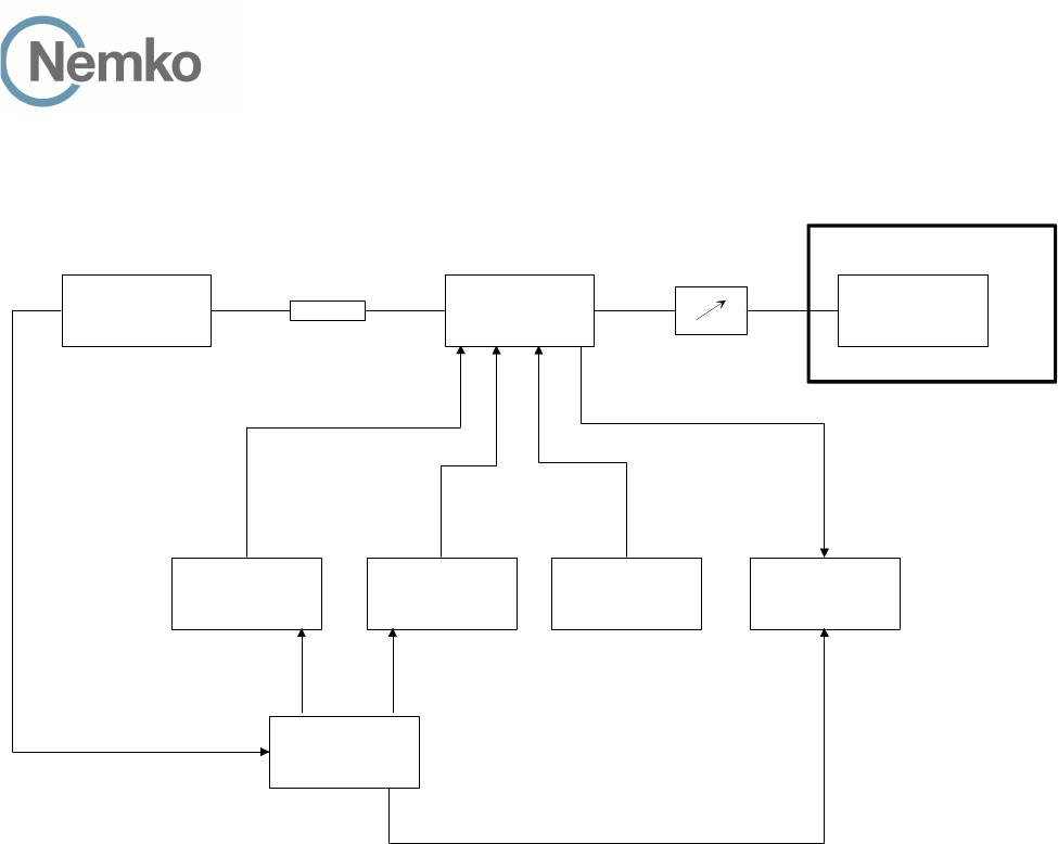
4.5 Monitoring Tests
EUT
Companion
Device
Generator 1 Generator 2 Generator 3 Spectrum
Analyzer
Pulse Pattern
Generator
CLK100
Sync signal
10 dB
Tunable
Attenuator
Combining
Device
Shielded Room
Test equipment: 2, 3, 4, 6, 9, 10, 11, 12, 13, 14, 15, 19, 23, 24, 25, 26, 29
Test Set-Up 6
This test setup is used for all Monitoring and Time and Spectrum Access Procedure tests. The path loss from
the signal generators to the EUT is measured with a power meter before the testing is started.
The CLK100 is used to synchronize the Pulse-/ Pattern generator to the start of the DECT frame, this signal
always comes from the base station. If the EUT is a DECT Portable Part (i.e. a handset) the CLK100 signal
will come form the Companion Device.
The sync signal to the Spectrum Analyzer is the CLK100 signal that is regenerated in the Pulse-/ Pattern
Generator, this is used to synchronize the Spectrum Analyzer to the DECT frame when in zero span. The
Pulse-/ Pattern Generator is used for tests that require time synchronized pulses or blocking of specific time
slots.
TEST REPORT
FCC part 15D
Report no.: 258223-5
FCC ID: ACJ96NKX-HNC600
Nemko Norway, Instituttveien 6, Kjeller, Norway Page 48 (48)
5 Test Equipment Used
To facilitate inclusion on each page of the test equipment used for related tests, each item of test equipment
and ancillaries are identified (numbered) by the Testhouse.
No. Model number Description Manufacturer Ref. no. Cal. date Cal. Due
1 FSW26 Spectrum Analyzer Rohde & Schwarz LR 1504 2013.08.30 2014.08.30
2 SME03 Signal generator Rohde & Schwarz LR 1238 2013.03.19 2015.03.19
3 SMIQ03B Signal generator Rohde & Schwarz LR 1516 2012.11.02 2014.11.02
4 SMHU52 Signal generator Rohde & Schwarz LR 1240 Cal b4 use
5 53310A Modulation Domain Analyzer Hewlett Packard LR 1483 2013.08.14 2015.08.14
6 81104A Pulse-/ Pattern Generator Agilent LR 1502 2013.03.19 2015.03.19
7 8470B Crystal Detector Hewlett Packard LR 1207 N/A
8 ESHS10 Measuring Receiver Rohde & Schwarz N- 3528 2012.06.28 2014.06.28
9 4768-10 Attenuator Narda LR1356 Cal b4 use
10 745-69 Step Attenuator Narda LR 1442 N/A
11 WE 1506A Power Splitter Weinchel LR 244 Cal b4 use
12 WE 1506A Power Splitter Weinchel LR 245 Cal b4 use
13 H-9 Hybrid Anzac LR 86 Cal b4 use
14 H-9 Hybrid Anzac LR 257 Cal b4 use
15 S212DS RF Switch Narda LR 1244 N/A
17 ESH3-Z5 Two Line V-Network Rohde & Schwarz LR 1076 Cal b4 use
19 6812B AC Power Source Agilent LR 1515 2013.10.28 2014.10.28
22 Model 87 V Multimeter Fluke N-4670 2013.10.07 2014.10.07
23 87H35-1 Circulator Racal-MESL s.no.: 140 N/A
24 87H35-1 Circulator Racal-MESL s.no.: 141 N/A
25 87H35-1 Circulator Racal-MESL s.no.: 142 N/A
26 U2000A USB Average Power Sensor Agilent LR 1523 2013.10.23 2015.10.23
27 ESH3-Z2 Pulse Limiter Rohde & Schwarz LR 1074 Cal b4 use
28 CMD60 DECT Tester Rohde & Schwarz LR 1335 2012.11.01 2014.11.01
29 FSP30 Spectrum Analyzer Rohde & Schwarz LR1551 2013.02.25 2015.02.25