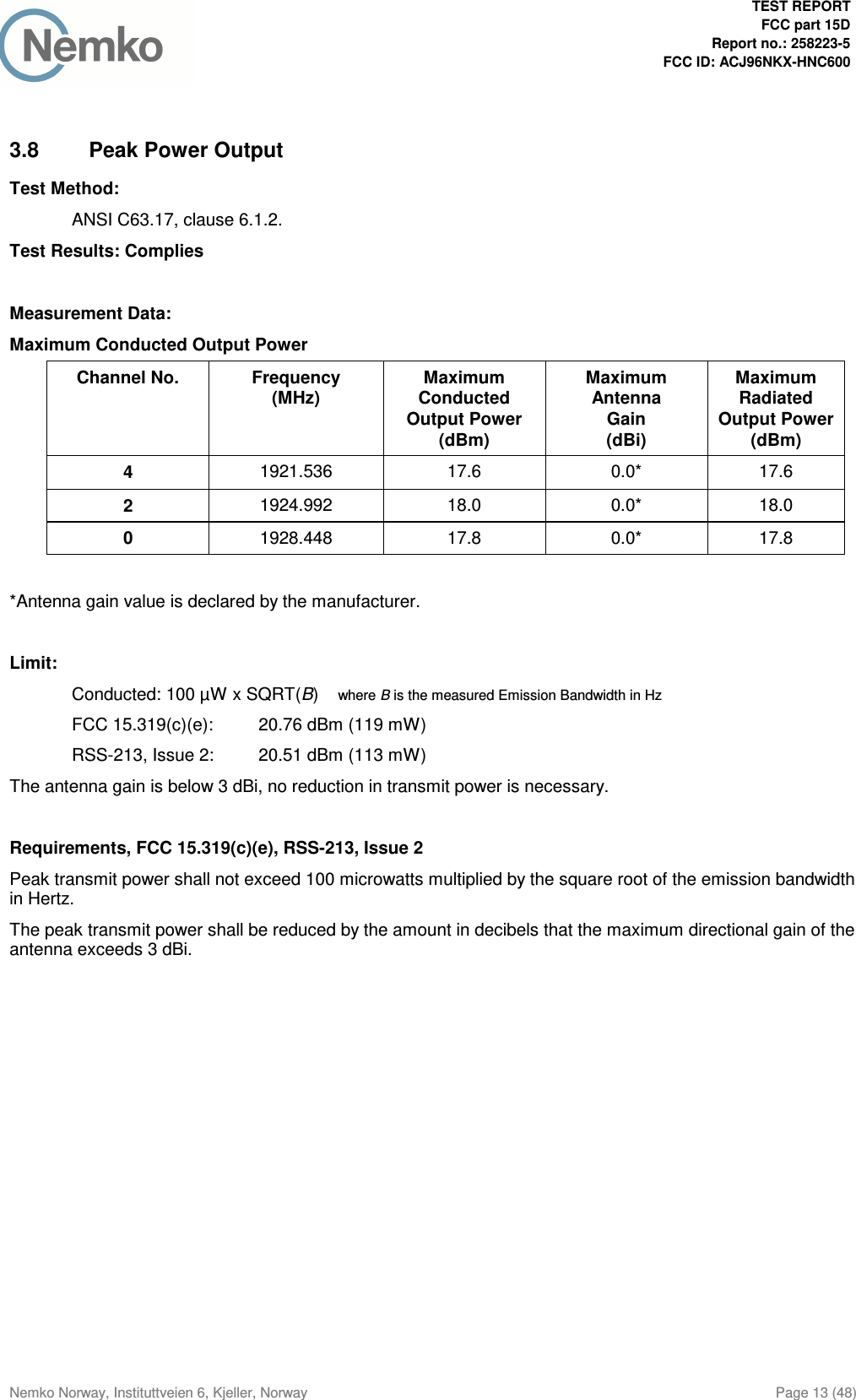
Panasonic of North America 96NKX-HNC600 DECT 6.0 Outdoor Camera User Manual 5 258223 KX HNC600 UPCS FCC15D
Panasonic Corporation of North America DECT 6.0 Outdoor Camera 5 258223 KX HNC600 UPCS FCC15D
Contents
- 1. Test Report
- 2. User Manual
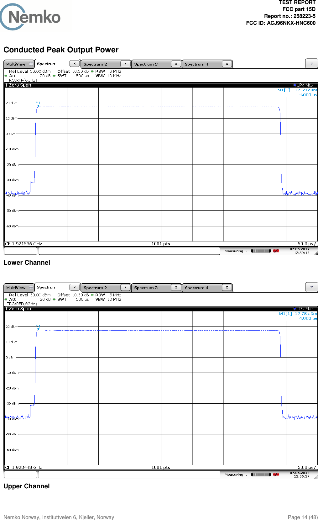
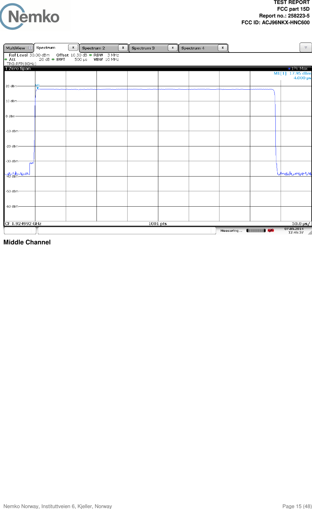
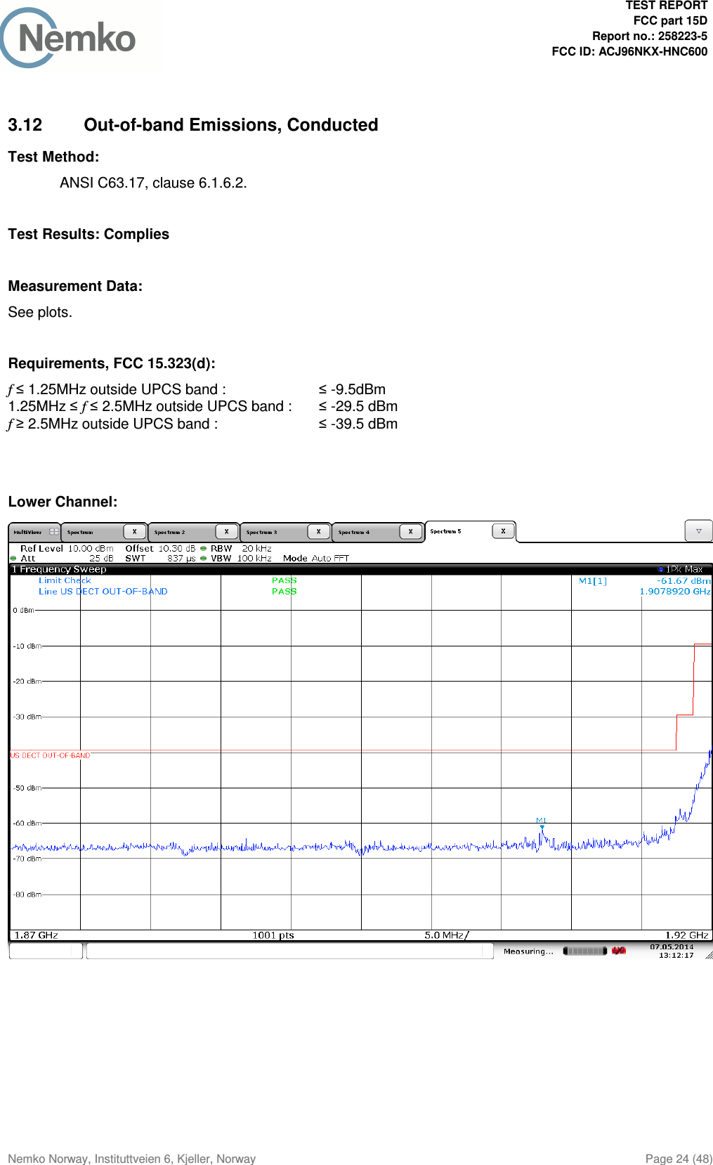
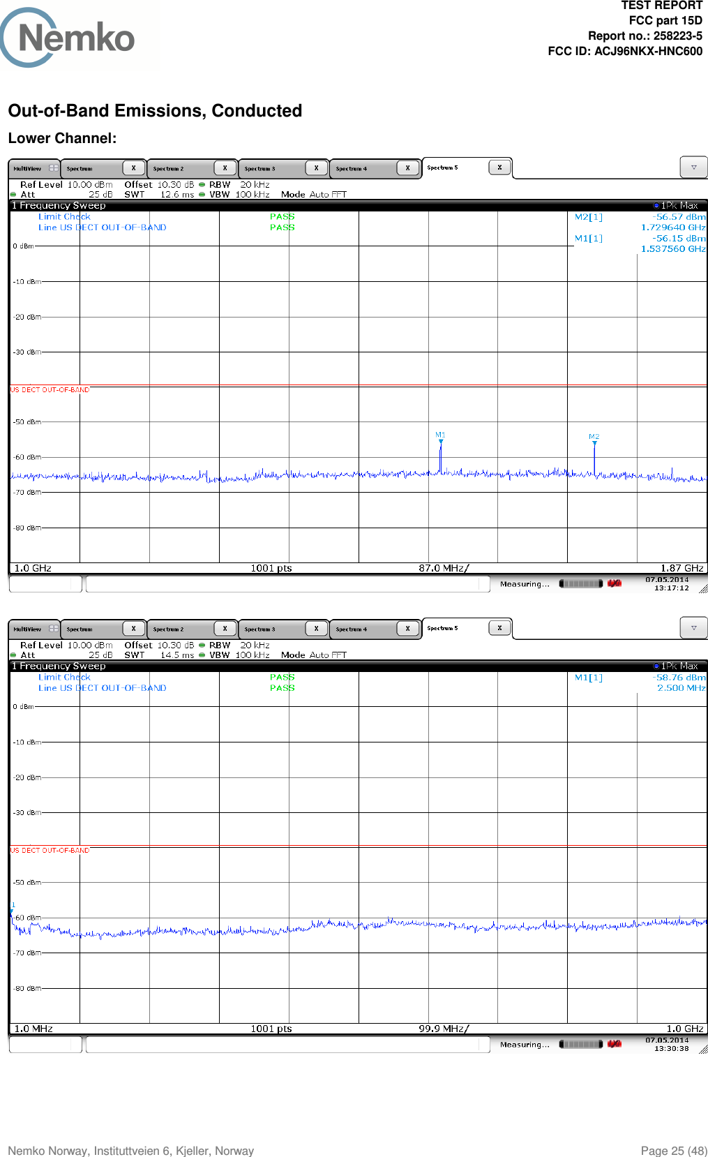
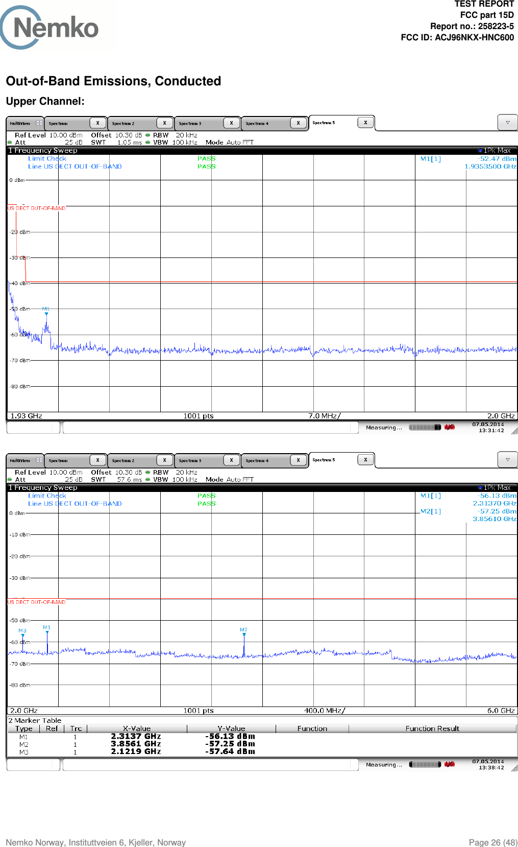
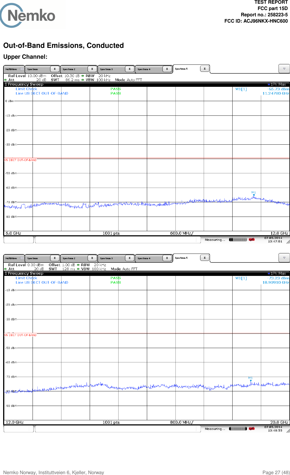
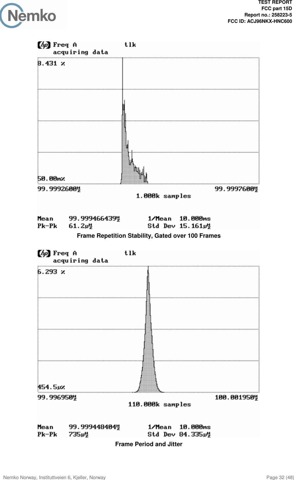
Test Report
![Report No. 258223-5 Template version: B Nemko Norway Nemko AS, Instituttveien 6, P.O. Box 96 Kjeller, 2007 Kjeller, Norway TEL +47 22 96 03 30 FAX +47 22 96 05 50 EMAIL info@nemko.com ENTERPRISE NUMBER NO974404532 nemko.com/no Test Report Product UPCS Transceiver in Outdoor Camera Name and address of the applicant Panasonic Corporation of North America Name and address of the manufacturer Panasonic System Networks Co., Ltd. 1-62, 4-chome, Minoshima, Hakata-ku Fukuoka 812-8531, Japan Model KX-HNC600 Rating 120 V AC (Mains) Trademark Panasonic Serial number / Additional information DECT 6.0 Tested according to FCC Part 15, subpart D Isochronous UPCS Device, 1920 – 1930 MHz Industry Canada RSS 213, Issue 2 2 GHz License-exempt Personal Communications Service Devices (LE-PCS) Order number 258223 Tested in period 2014.05.07 to 2014.05.14 Issue date 2014.05.26 Name and address of the testing laboratory Instituttveien 6 Kjeller, Norway FCC No: 994405 IC OATS: 2040D-1 TEL: (+47) 22 96 03 30 FAX: (+47) 22 96 05 50 Prepared by [Frode Sveinsen] Approved by [G.Suhanthakumar] This report shall not be reproduced except in full without the written approval of Nemko. Opinions and interpretations expressed within this report are not part of the current accreditation. This report was originally distributed electronically with digital signatures. For more information contact Nemko.](https://usermanual.wiki/Panasonic-of-North-America/96NKX-HNC600.Test-Report/User-Guide-2304420-Page-1.png)
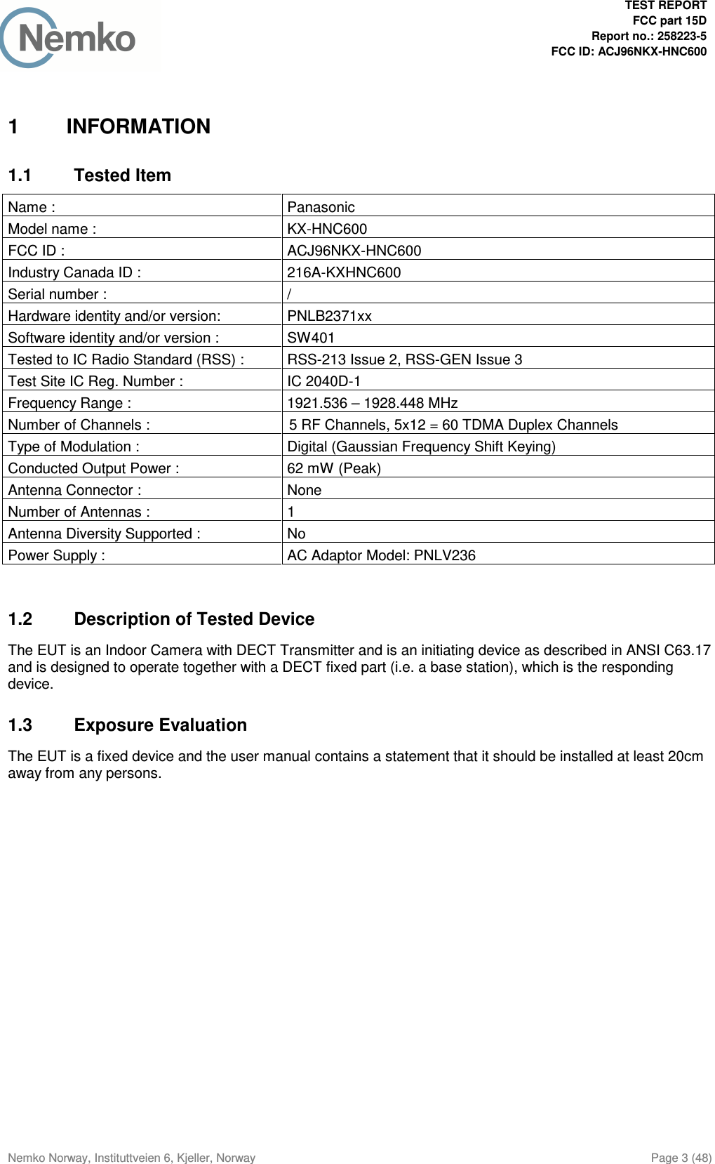
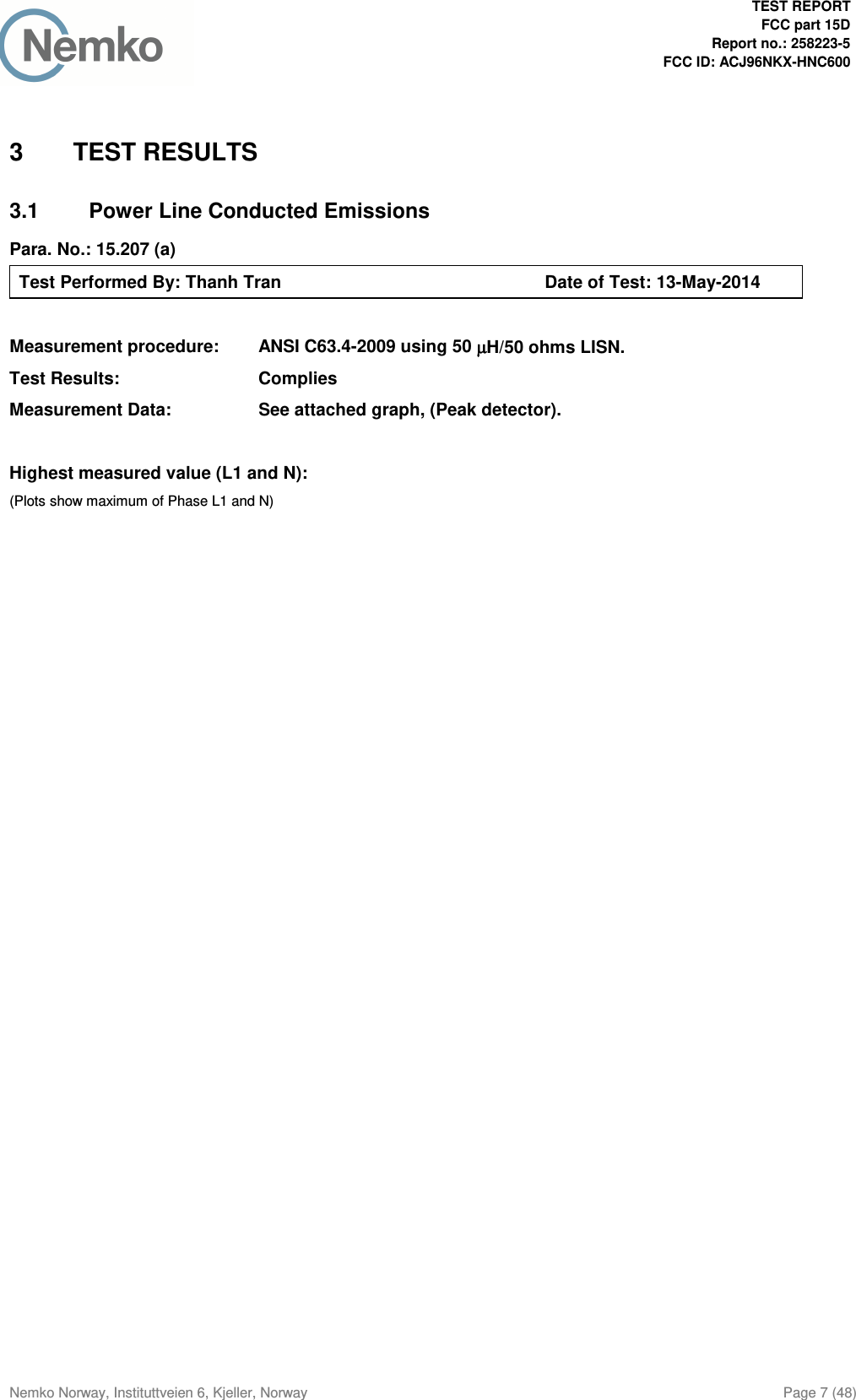
![TEST REPORT FCC part 15D Report no.: 258223-5 FCC ID: ACJ96NKX-HNC600 Nemko Norway, Instituttveien 6, Kjeller, Norway Page 8 (48) Standby Mode with PNLV236 Adaptor, 120V 60Hz: Frequency Level Af Limit Margin Det Position Verdict [MHz] [dBuV] [dB] [dBuV] [dB] [Pass/Fail] 0.395000 39.00 10.20 58.00 19.00 QP L1 Pass 0.370000 29.00 10.20 48.50 19.50 AV L1 Pass 0.395000 36.50 10.20 48.00 11.50 AV L1 Pass 0.445000 20.20 10.20 47.00 26.80 AV L1 Pass 0.480000 11.20 10.20 46.30 35.10 AV L1 Pass 0.740000 22.10 10.20 46.00 23.90 AV L1 Pass 0.760000 19.40 10.20 46.00 26.60 AV L1 Pass 0.785000 17.40 10.20 46.00 28.60 AV N Pass 0.815000 19.90 10.20 46.00 26.10 AV N Pass 0.840000 18.90 10.20 46.00 27.10 AV N Pass 0.945000 15.10 10.20 46.00 30.90 AV N Pass 1.155000 17.10 10.20 46.00 28.90 AV N Pass 1.180000 15.00 10.20 46.00 31.00 AV N Pass 1.240000 11.70 10.20 46.00 34.30 AV L1 Pass 1.455000 13.90 10.20 46.00 32.10 AV L1 Pass 22.325000 14.30 11.30 50.00 35.70 AV N Pass Transmit Mode with PNLV236 Adaptor, 120V 60Hz: Frequency Level Af Limit Margin Det Position Verdict [MHz] [dBuV] [dB] [dBuV] [dB] [Pass/Fail] 0.395000 39.20 10.20 58.00 18.80 QP L1 Pass 0.750000 30.30 10.20 56.00 25.70 QP N Pass 0.170000 16.00 10.10 55.00 39.00 AV L1 Pass 0.370000 28.40 10.20 48.50 20.10 AV L1 Pass 0.395000 36.50 10.20 48.00 11.50 AV L1 Pass 0.570000 17.30 10.20 46.00 28.70 AV N Pass 0.750000 9.00 10.20 46.00 37.00 AV N Pass 0.785000 18.00 10.20 46.00 28.00 AV N Pass 0.830000 6.90 10.20 46.00 39.10 AV N Pass 0.865000 17.00 10.20 46.00 29.00 AV N Pass 0.950000 12.00 10.20 46.00 34.00 AV N Pass 1.695000 10.70 10.20 46.00 35.30 AV L1 Pass 1.925000 12.20 10.20 46.00 33.80 AV L1 Pass 8.670000 15.10 10.60 50.00 34.90 AV L1 Pass 12.200000 13.00 10.70 50.00 37.00 AV L1 Pass 18.000000 11.30 11.00 50.00 38.70 AV L1 Pass 22.205000 15.20 11.30 50.00 34.80 AV N Pass](https://usermanual.wiki/Panasonic-of-North-America/96NKX-HNC600.Test-Report/User-Guide-2304420-Page-8.png)
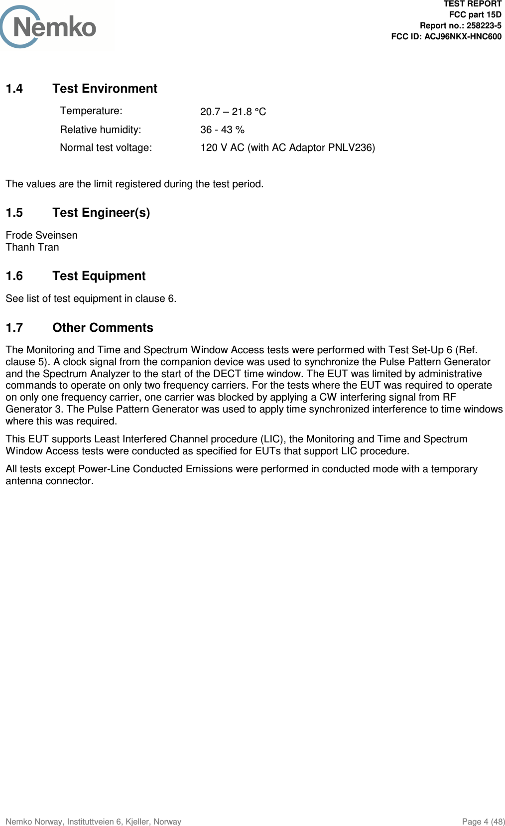
![TEST REPORT FCC part 15D Report no.: 258223-5 FCC ID: ACJ96NKX-HNC600 Nemko Norway, Instituttveien 6, Kjeller, Norway Page 9 (48) 01020304050607080Level [dBµV]150k 300k 500k 1M 2M 3M 5M 7M 10M 30MFrequency [Hz]+++++++++++++++xx MES 258223N_Qp + MES 258223N_Av MES 258223N LIM EN 55022 V QP LIM EN 55022 V AV Standby Mode with PNLV236 Adaptor, 120V 60Hz 01020304050607080Level [dBµV]150k 300k 500k 1M 2M 3M 5M 7M 10M 30MFrequency [Hz]+++++++++++++++xxx MES 258223N_Qp + MES 258223N_Av MES 258223N LIM EN 55022 V QP LIM EN 55022 V AV Transmit Mode with PNLV236 Adaptor, 120V 60Hz](https://usermanual.wiki/Panasonic-of-North-America/96NKX-HNC600.Test-Report/User-Guide-2304420-Page-9.png)
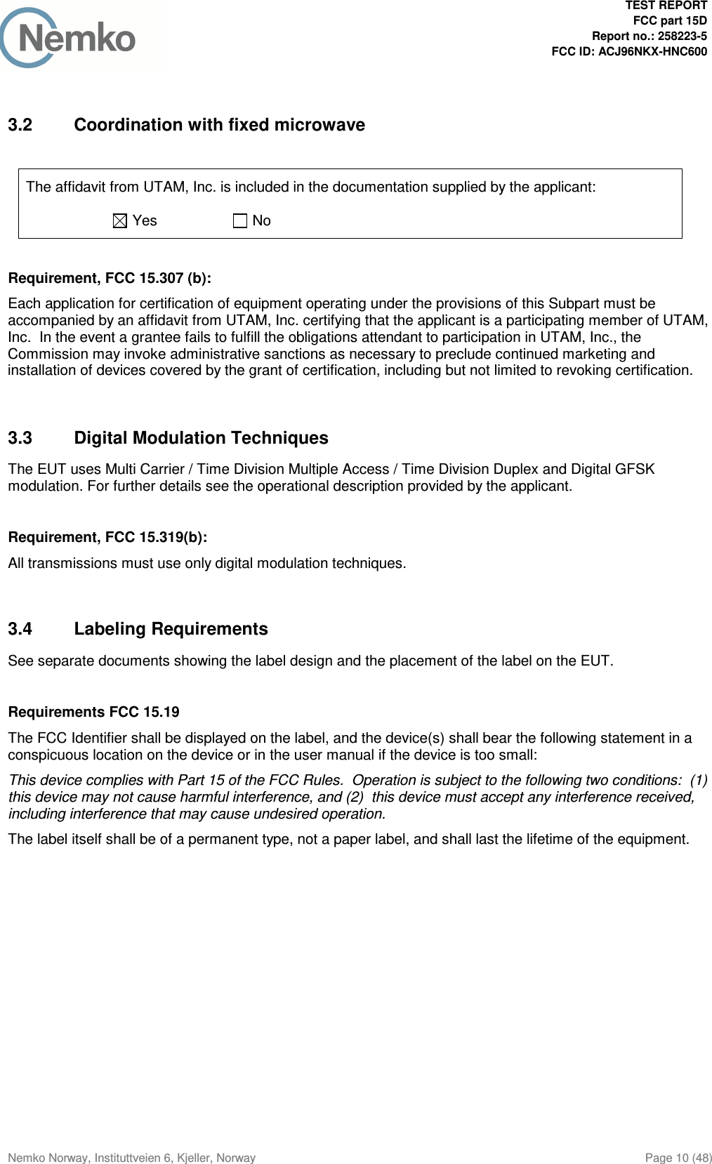
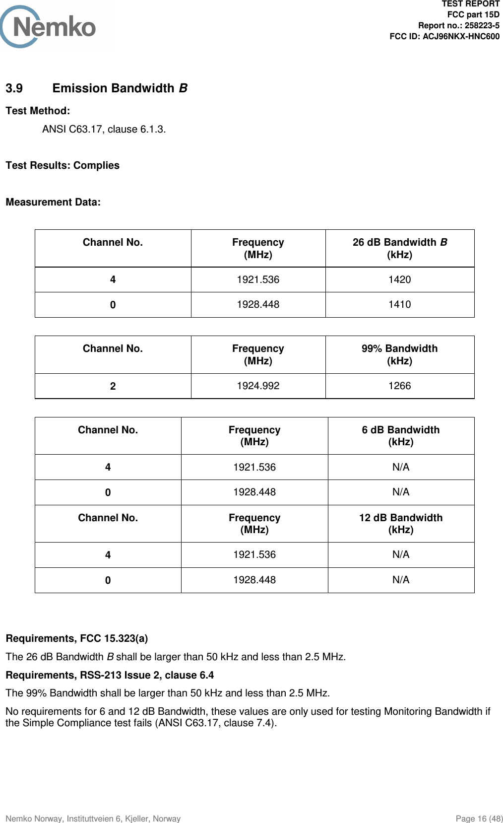
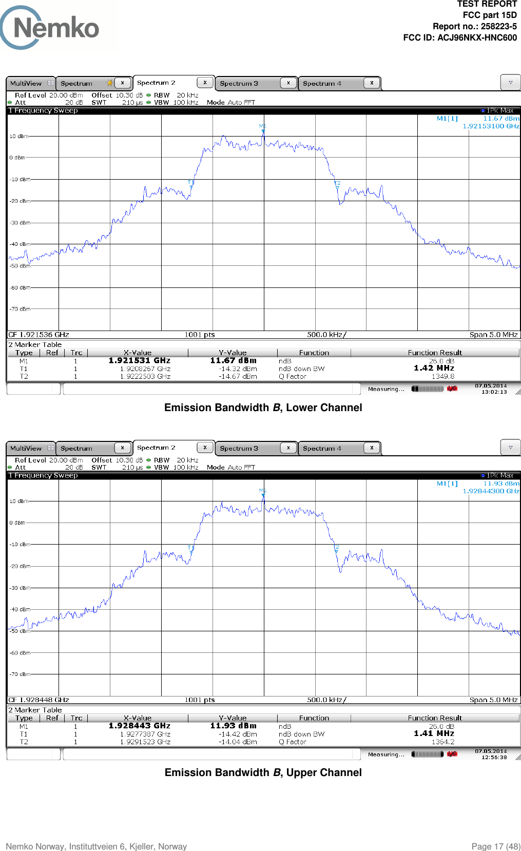
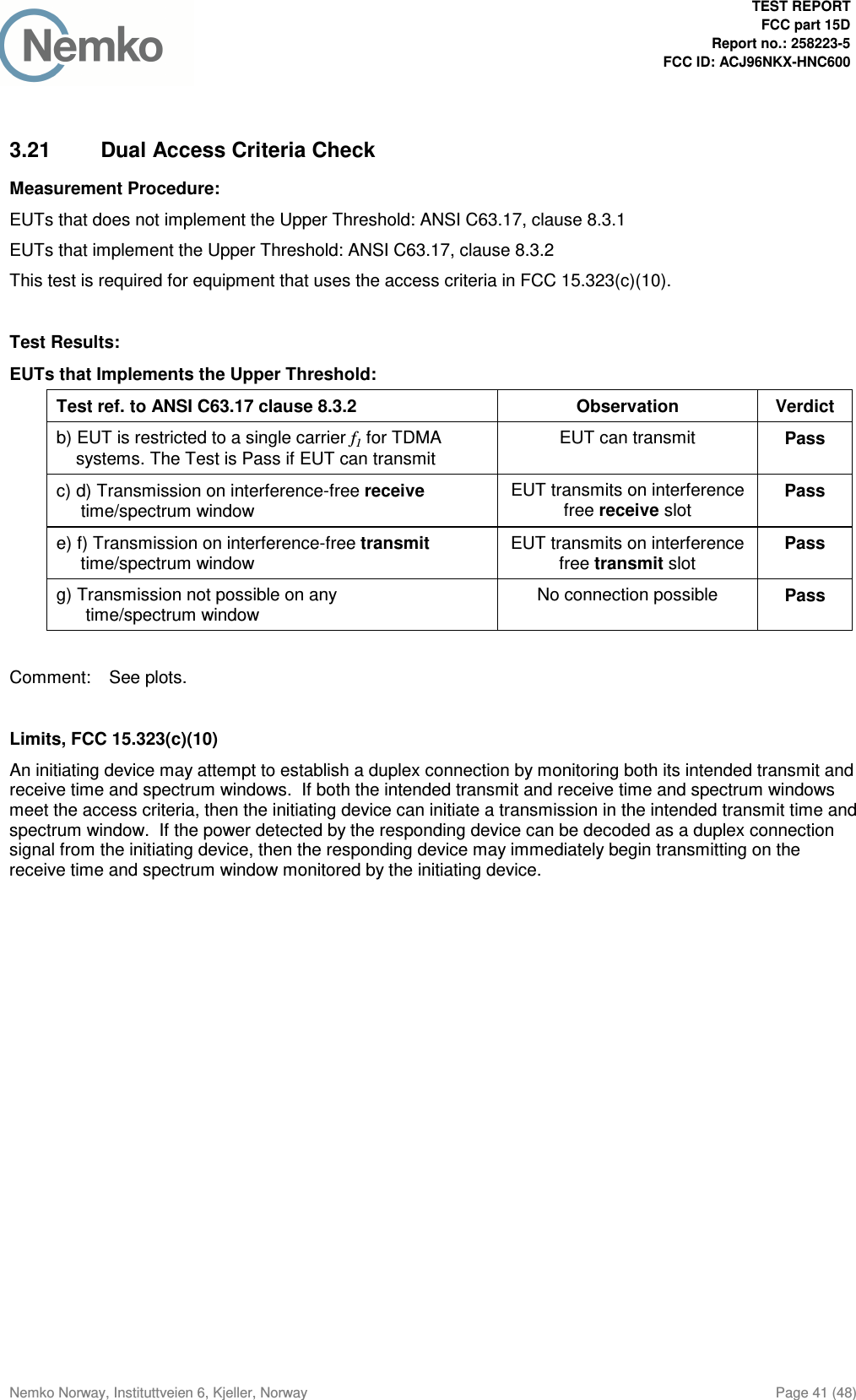
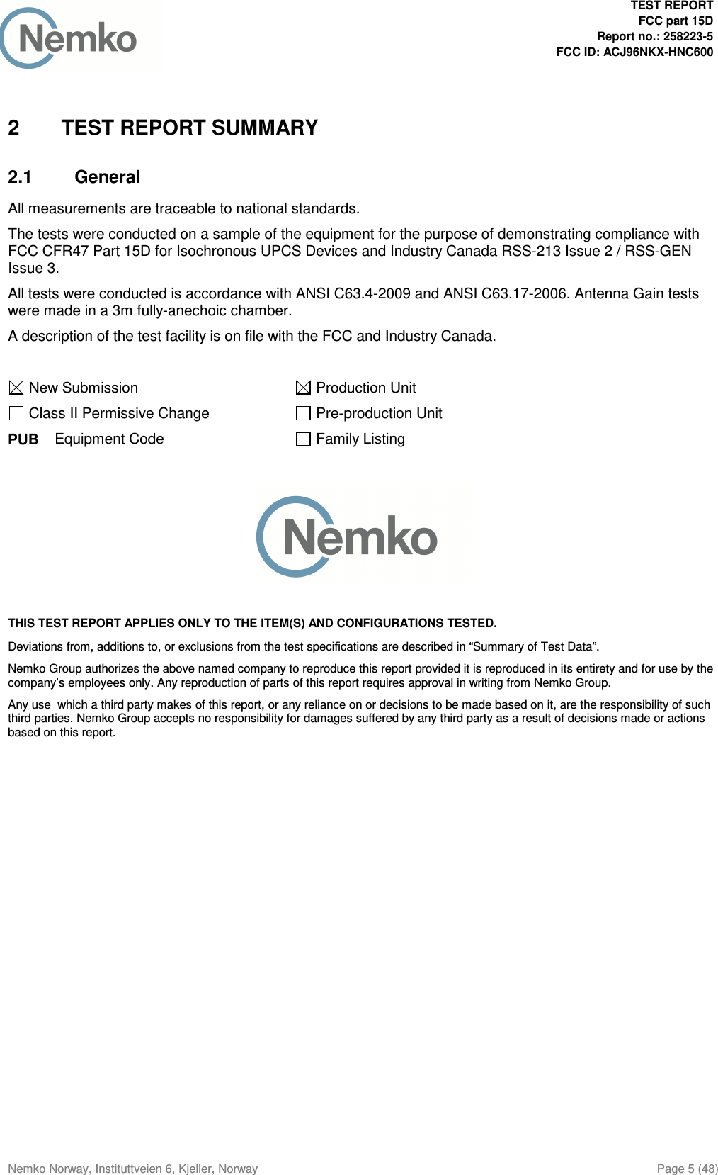
![TEST REPORT FCC part 15D Report no.: 258223-5 FCC ID: ACJ96NKX-HNC600 Nemko Norway, Instituttveien 6, Kjeller, Norway Page 34 (48) Selected Channel Confirmation, FCC 15.323(c)(1) and (5) ANSI C63.17 clause 7.3.4 Observation Verdict b) Shall not transmit on f1 EUT transmits on f2 Pass d) Shall not transmit on f2 EUT transmits on f1 Pass Limits: FCC 15.323 RSS-213, Issue 2 Lower Threshold + 6 dB margin -73.7 dBm -74.4 dBm Upper Threshold + 6 dB margin N/A -54.4 dBm Ref 0 dBm 3.03 sAtt 10 dB 3.03 s* 3.03 sCLRWR 3.03 s A 3.03 sSGL 3.03 sRBW 300 kHz 3.03 s VBW 1 MHz 3.03 sSWT 5 s 3.03 sCenter 1.923264 GHz 3.03 s500 ms/ 3.03 sTRG 3.03 s* 3.03 s1 PK 3.03 s 3.03 s 3.03 s 3.03 s 3.03 s 3.03 s 3.03 s 3.03 s 3.03 s 3.03 s-100-90-80-70-60-50-40-30-20-100 3.03 s1Marker 1 [T1 ] -50.58 dBm 329.924000 ms 2Delta 2 [T1 ] 30.77 dB 3.030000 s DELTA MARKER 2 3.03 sDate: 12.MAY.2014 14:33:00 7.3.4 Selected Channel Confirmation, Connection 3.0s After Interferer Removed](https://usermanual.wiki/Panasonic-of-North-America/96NKX-HNC600.Test-Report/User-Guide-2304420-Page-34.png)
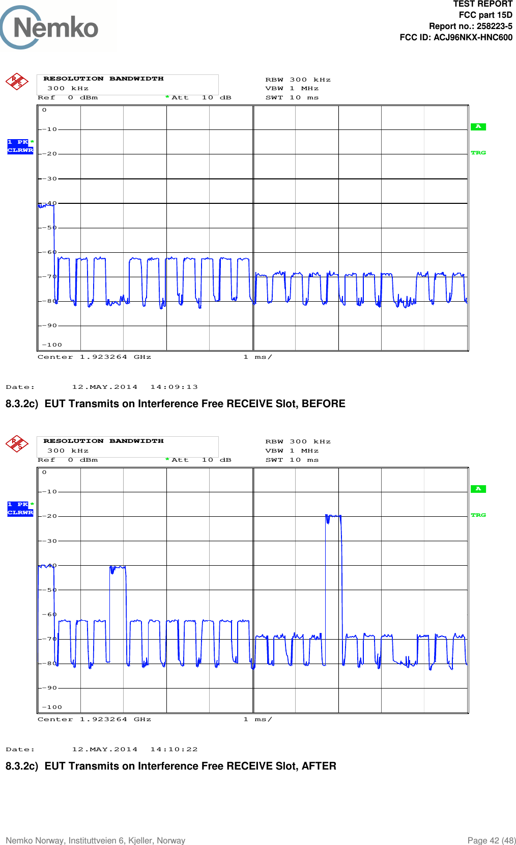
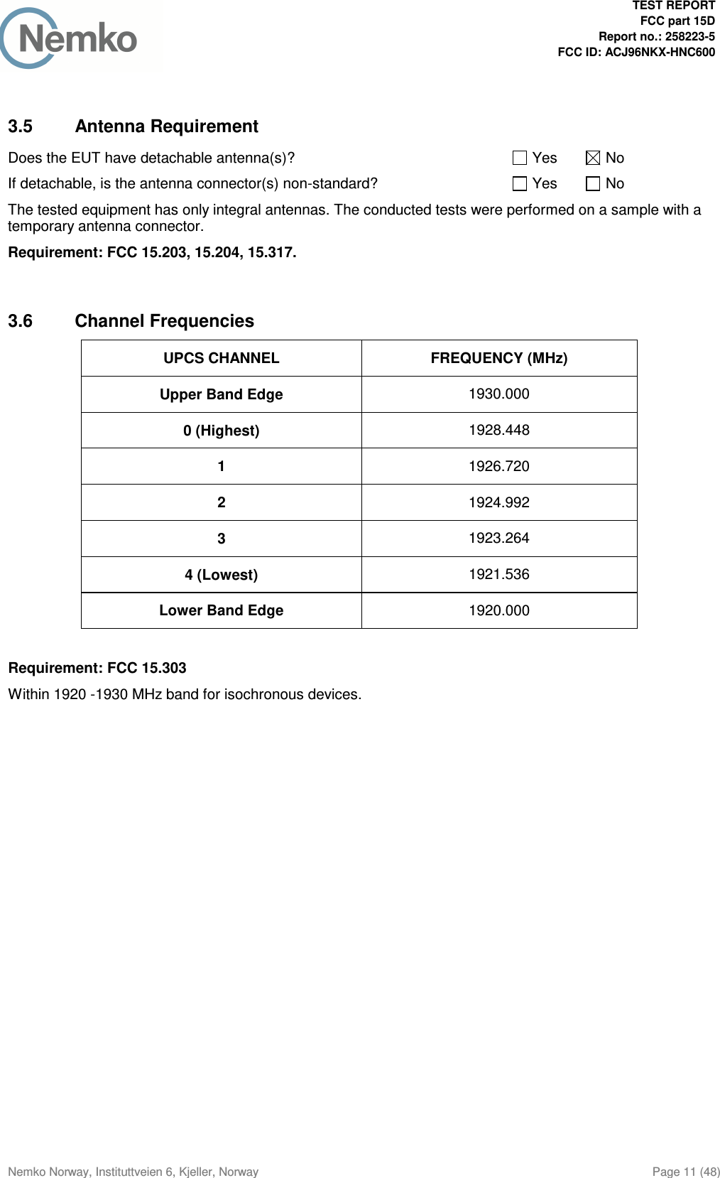
![TEST REPORT FCC part 15D Report no.: 258223-5 FCC ID: ACJ96NKX-HNC600 Nemko Norway, Instituttveien 6, Kjeller, Norway Page 40 (48) Ref 0 dBm 324 msAtt 10 dB 324 ms* 324 msCLRWR 324 ms A 324 msTRG 324 msRBW 1 MHz 324 ms VBW 3 MHz 324 ms 324 ms 324 ms 324 ms 324 ms 324 ms 324 ms 324 ms 324 ms 324 msCenter 1.923264 GHz 324 ms200 ms/ 324 msSWT 2 s 324 msSGL 324 ms* 324 ms1 PK 324 ms-100-90-80-70-60-50-40-30-20-100 324 ms1Marker 1 [T1 ] -18.93 dBm 1.447924 s 2Delta 2 [T1 ] -0.00 dB 324.000000 ms DELTA MARKER 2 324 msDate: 12.MAY.2014 14:05:34 8.2.1a) Initial Transmission Without Acknowledgements Ref 0 dBm 9.992 sAtt 10 dB 9.992 s* 9.992 sCLRWR 9.992 s A 9.992 sTRG 9.992 sRBW 1 MHz 9.992 s VBW 3 MHz 9.992 s 9.992 s 9.992 s 9.992 s 9.992 s 9.992 s 9.992 s 9.992 s 9.992 s 9.992 sCenter 1.923264 GHz 9.992 s1.2 s/ 9.992 sSWT 12 s 9.992 sSGL 9.992 s* 9.992 s1 PK 9.992 s-100-90-80-70-60-50-40-30-20-100 9.992 s1Marker 1 [T1 ] -18.07 dBm 1.179924 s 2Delta 2 [T1 ] -0.21 dB 9.992000 s DELTA MARKER 2 9.992 sDate: 12.MAY.2014 13:43:01 8.2.1c) Transmission Time After Loss of Acknowledgements](https://usermanual.wiki/Panasonic-of-North-America/96NKX-HNC600.Test-Report/User-Guide-2304420-Page-40.png)