Panasonic of North America 96NKX-HTS824 Hybrid IP-PBX User Manual
Panasonic Corporation of North America Hybrid IP-PBX Users Manual
UserManual.wiki
>
Panasonic of North America
>
96NKX HTS824 User Manual
Users Manual
Navigation menu
Upload a User Manual
Namespaces
Wiki Guide
HTML
PDF
Info
Views
User Manual
Discussion / Help
Navigation
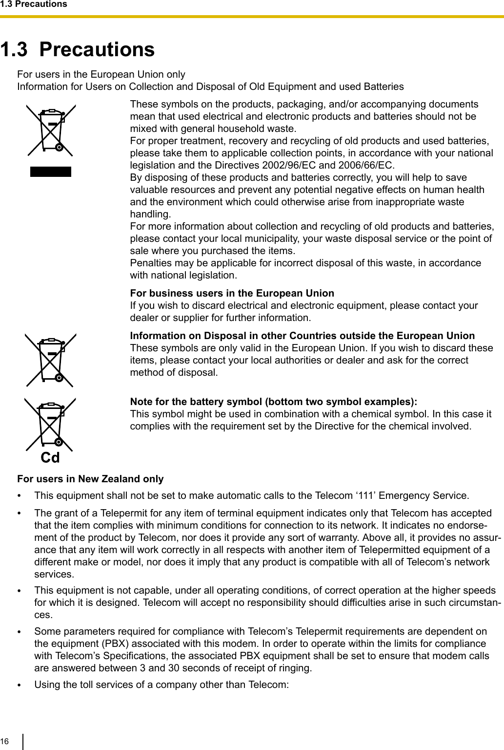
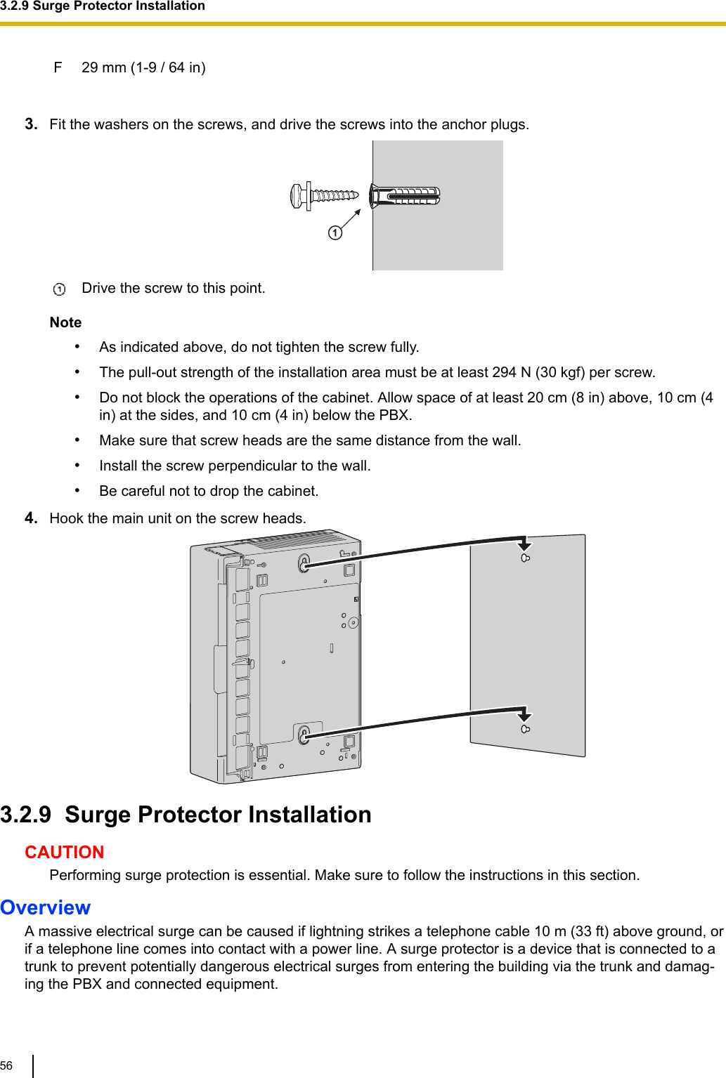
![b. If liquid has been spilled into the product.c. If the product has been exposed to rain or water.d. If the product does not operate according to the operating instructions. Adjust only the controls thatare explained in the operating instructions. Improper adjustment of other controls may result in dam-age and may require service by a qualified technician to restore the product to normal operation.e. If the product has been dropped or the cabinet has been damaged.f. If product performance deteriorates. For the PBX•Do not insert foreign objects of any kind into this product, as they may touch dangerous voltage points orshort out parts that could result in a fire or electric shock.•Do not pull, bend, rest objects on, or chafe the power cord and plug. Damage to the power cord or plugcan cause fire or electric shock.•Do not attempt to repair the power cord or plug. If the power cord or plug is damaged or frayed, contactan authorised Panasonic Factory Service Centre for a replacement.•Do not use the product in health care facilities if any regulations posted in the area instruct you not to doso. Hospitals or health care facilities may be using devices sensitive to external RF (radio frequency)energy.•Do not leave the slot open if an option service card is not installed after removing a dummy cover plate.Make sure to insert the slot cover included with the option service card into the slot.•If damage to the unit exposes any internal parts, disconnect the power supply cord immediately and re-turn the unit to your dealer.•To prevent fires, electric shock, injury, or damage to the product, be sure to follow these guidelines whenperforming any wiring or cabling:a. Before performing any wiring or cabling, unplug the product's power cord from the outlet. After com-pleting all wiring and cabling, plug the power cord back into the outlet.b. When laying cables, do not bundle the product's power cord with the power cords of other devices.c. Do not place any objects on top of the cables connected to the PBX.d. When running cables along the floor, use protectors to prevent the cables from being stepped on.e. Do not run any cables under carpeting.•Unplug this unit from the AC outlet if it emits smoke, an abnormal smell or makes unusual noise. Theseconditions can cause fire or electric shock. Confirm that smoke has stopped and contact an authorisedPanasonic Factory Service Centre.•Make sure that the wall that the unit will be attached to is made of concrete or thick wood, and is strongenough to support the unit (approx. 11 kg [24 lb]). Do not attach the unit to walls made from plasterboardor thin plywood. Attaching the unit to areas where there are strong winds, or where shocks or vibrationsare frequent or strong, may lead to the product falling over.•Only use the wall-mounting equipment (screws and washers) included with the PBX.•The earthing wire of the AC cable has an effect against external noise and lightning strikes, but it maynot be enough to protect the PBX and to ensure electromagnetic compatibility. A permanent connectionbetween earth and the earth terminal of the PBX must be made.1.1 For Your Safety10](https://usermanual.wiki/Panasonic-of-North-America/96NKX-HTS824/User-Guide-2904004-Page-10.png)
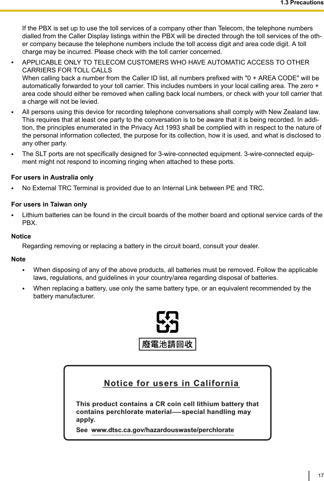
![CAUTIONFor All Telephone Equipment•The product should be kept free of dust, moisture, high temperature (more than 40 °C [104 °F]) and vi-bration, and should not be exposed to direct sunlight.•Unplug the product from the wall outlet before cleaning. Wipe the product with a soft cloth. Do not cleanwith abrasive powders or with chemical agents such as benzine or thinner. Do not use liquid cleaners oraerosol cleaners. For the PBX•Do not install the system in the following locations:a. In direct sunlight and hot, cold, or humid places. (Temperature range: 0 °C to 40 °C [32 °F to104 °F])b. Areas where sulphuric gases may be present, such as near thermal springs.c. Near devices that generate high frequencies, such as sewing machines or electric welders.d. Locations where other objects will obstruct the area around the PBX. Be especially careful to leaveat least 5 cm (2 in) to the sides of the PBX for ventilation.e. Locations where condensation can occur.•Do not block the openings of the PBX. Allow space of at least 20 cm (8 in) above, 10 cm (4 in) at thesides, and 10 cm (4 in) below the PBX.•When installing or removing the optional service cards, do not put pressure on any parts of the motherboard. Doing so may result in damage to the PBX.•Once you have started the PBX, if you unplug the PBX, do not initialise it again as described in "SystemInitialisation Procedure". Otherwise, your programmed data will be cleared. To restart the PBX, refer to"6.1.4 Restarting the PBX".•Before touching the product (PBX, cards, etc.), discharge static electricity by touching ground or wearingan earthing strap. Failure to do so may cause the PBX to malfunction due to static electricity.•When relocating the equipment, first disconnect the telecom connection before disconnecting the powerconnection. When the unit is installed in the new location, reconnect the power first, and then reconnectthe telecom connection.•The plug of power supply cordset is used as the main disconnect device. Ensure that the AC outlet islocated near the equipment and is easily accessible.•Slots and openings in the front, back and bottom of the cabinet are provided for ventilation; to protect itfrom overheating, these openings must not be blocked or covered. The openings should never beblocked by placing the product on a bed, sofa, rug, or other similar surface while in use. The productshould never be placed near or over a radiator or other heat source. This product should not be placedin a sealed environment unless proper ventilation is provided.1.1 For Your Safety12](https://usermanual.wiki/Panasonic-of-North-America/96NKX-HTS824/User-Guide-2904004-Page-12.png)
![1.4 Data SecurityIn order to use the PBX safely and correctly, the Security Requirements below must be observed. Failure todo so may result in:•Loss, leakage, falsification or theft of user information.•Illegal use of the PBX by a third party.•Interference or suspension of service caused by a third party. What is User Information?User Information is defined as:Information sent from the PBX to a PC or a USB memory device, such as system data files. Requirements1. Always make backups of data stored on the System memory and/or perform regular system data back-ups to a USB memory device. Refer to "Maintenance-[2-3]System Control-System Data Backup- ◆Sys-tem Data Backup" in the Programming Item List.2. To prevent illegal access from the Internet, activate a Firewall.3. To avoid unauthorised access and possible abuse of the PBX, we strongly recommend:a. Keeping the password secret.b. Selecting a complex, random password that cannot be easily guessed.c. Changing your password regularly.4. Perform the following when sending the PBX for repair or handing it over to a third party.a. Make a backup of data stored on the System memory.5. When user information is sent from the PBX to a PC or a USB memory device, the confidentiality of thatinformation becomes the responsibility of the customer. Before disposing of the PC or the USB memorydevice, ensure that data cannot be retrieved from it by formatting the hard disk and/or rendering it physi-cally unusable.1.5 F.C.C. REQUIREMENTS AND RELEVANTINFORMATION1. Notification to the Telephone CompanyThis equipment complies with Part 68 of the FCC rules and the requirements adopted by the ACTA. Onthe side of this equipment is a label that contains, among other information, a product identifier in theformat US: ACJIS04BKX-HTS824. If requested, this number must be provided to the telephone compa-ny.Installation must be performed by a qualified professional installer. If required, provide the telephonecompany with the following technical information:•Telephone numbers to which the system will be connected•Make: Panasonic•Model: KX-HTS824•Certification No.: found on the side of the unit•Ringer Equivalence No.: 0.4B•Facility Interface Code: 02LS2•Service Order Code: 9.0F•Required Network Interface Jack: RJ11C1.4 Data Security19](https://usermanual.wiki/Panasonic-of-North-America/96NKX-HTS824/User-Guide-2904004-Page-19.png)

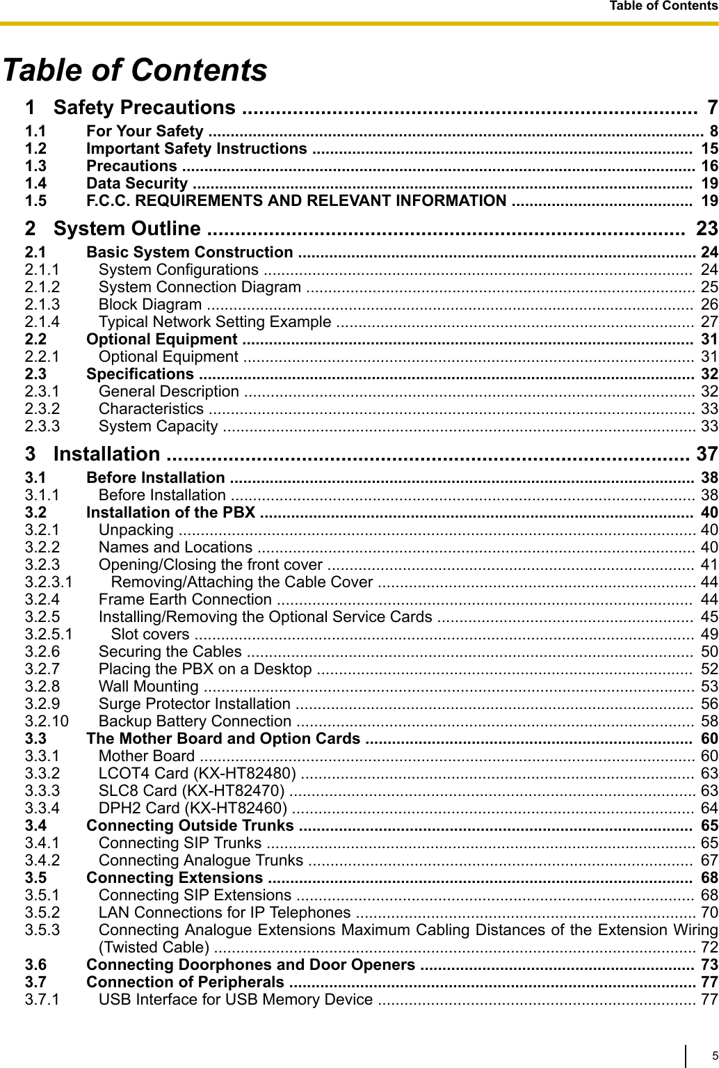
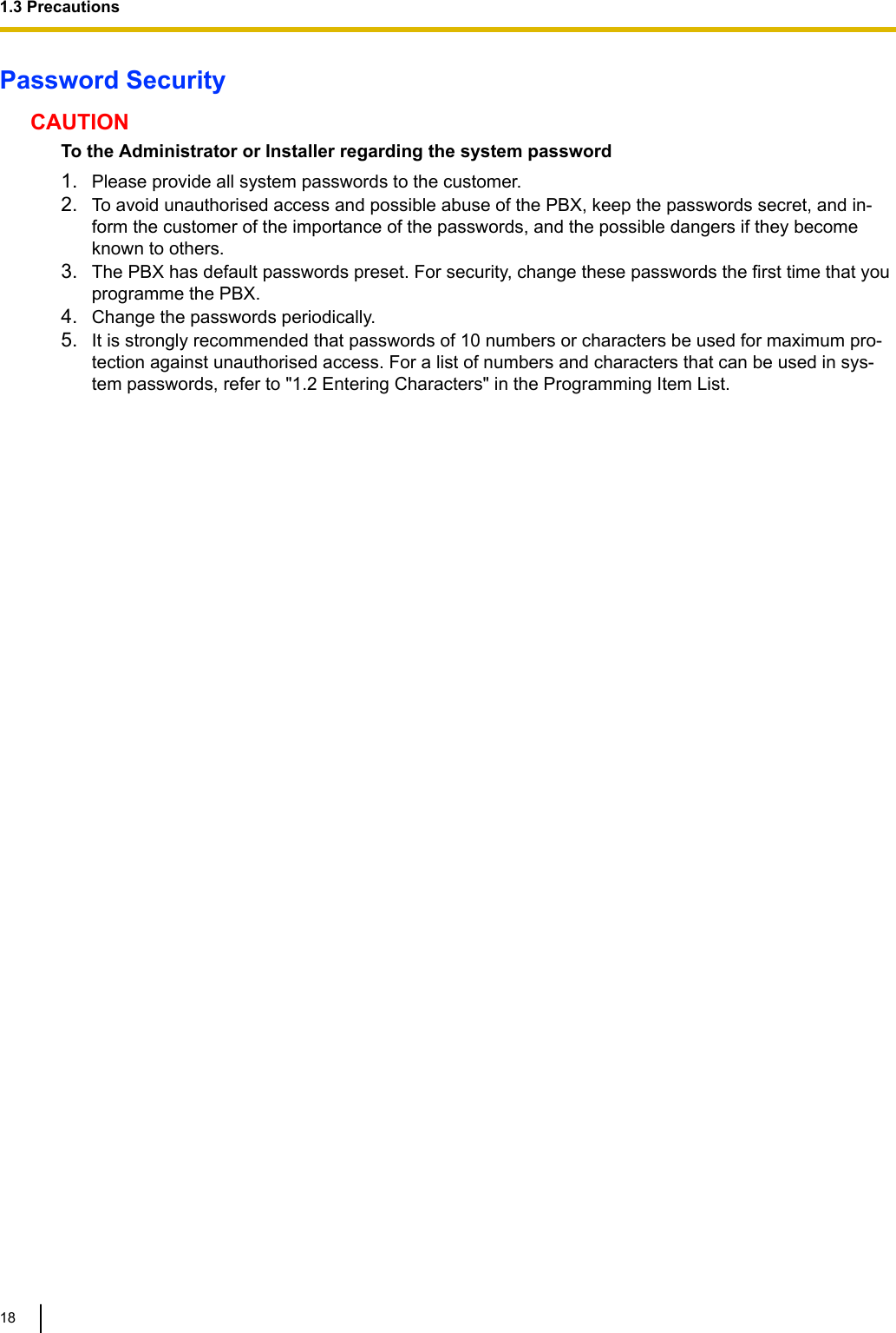
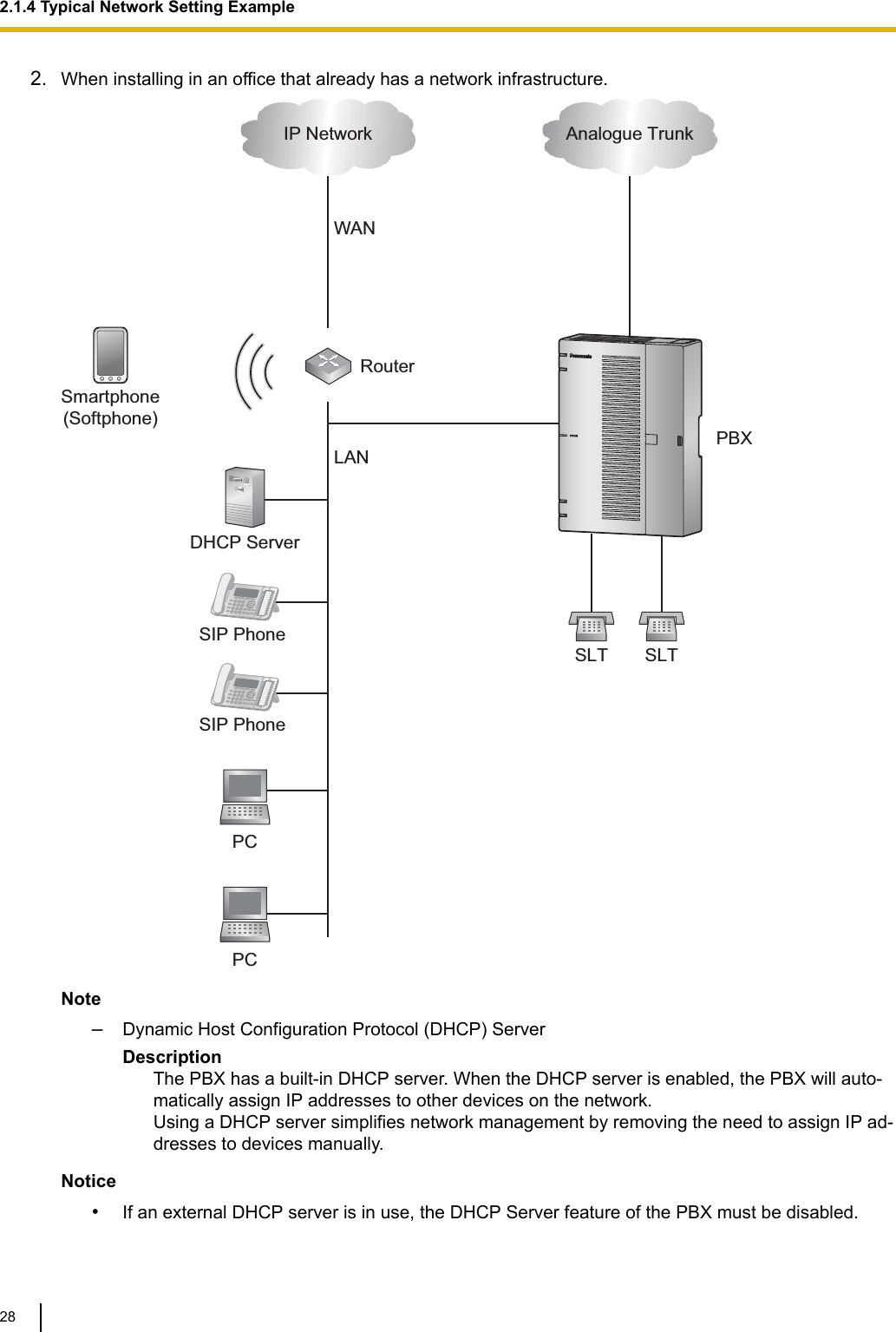
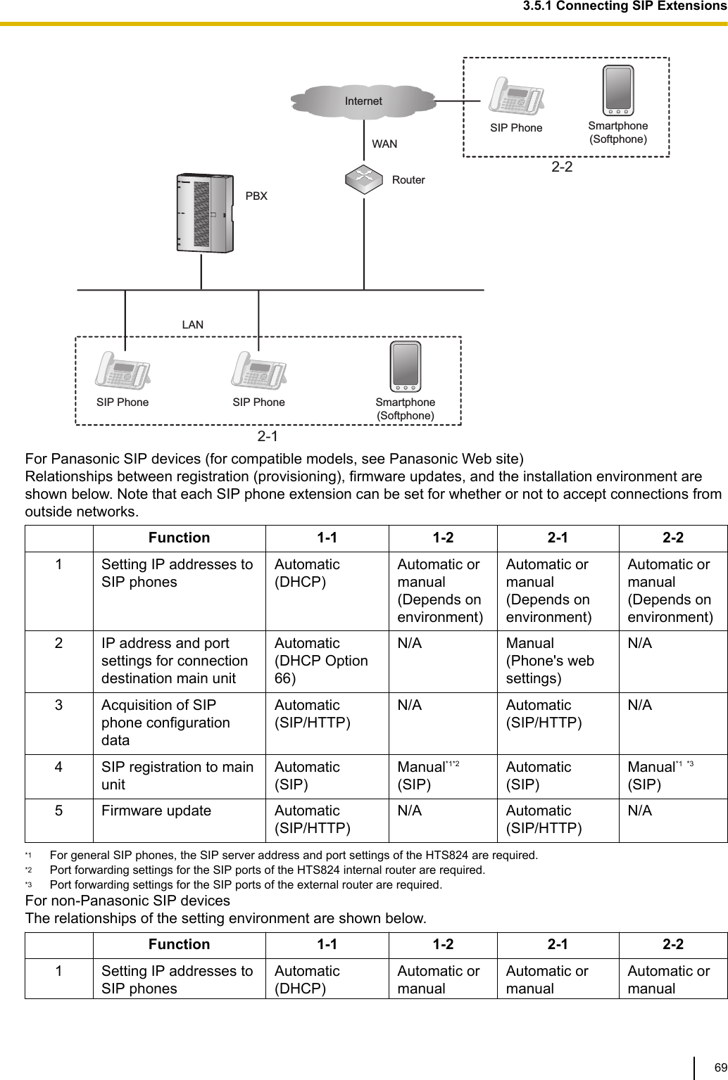
![2.1.4 Typical Network Setting ExampleAn example of typical network connection is shown below.1. When installing in a new office or an office where there is no network infrastructure.RouterPBXIP Network Analogue TrunkSLT SLTSmartphone(Softphone)SIP Phone LANWANSIP Phone PCPCSwitching HubNotice•Refer to the following when the internal DHCP server will be used.For details about DHCP server settings, refer to "Network Configuration-[4-2]LAN Settings-◆DHCP Mode" in the Programming Item List.2.1.4 Typical Network Setting Example27](https://usermanual.wiki/Panasonic-of-North-America/96NKX-HTS824/User-Guide-2904004-Page-27.png)
![For details about DHCP server settings, refer to "Network Configuration-[4-2]LAN Settings-◆DHCP Mode" in the Programming Item List.2.1.4 Typical Network Setting Example29](https://usermanual.wiki/Panasonic-of-North-America/96NKX-HTS824/User-Guide-2904004-Page-29.png)
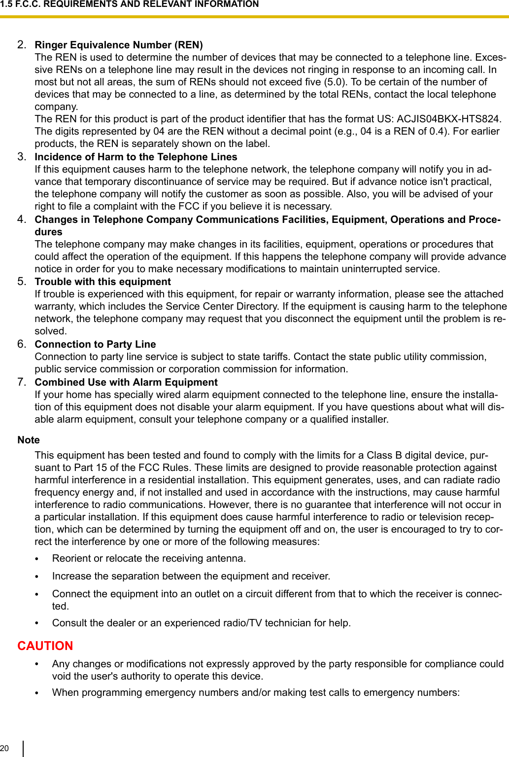
![3. When installing the PBX without connecting it to an existing network.Switching HubIP Network Analogue TrunkRouterWANLANSLT SLTPBXSmartphone(Softphone)SIP Phone SIP Phone PCPCNotice•Refer to the following when the internal DHCP server will be used.For details about DHCP server settings, refer to "Network Configuration-[4-2]LAN Settings-◆DHCP Mode" in the Programming Item List.2.1.4 Typical Network Setting Example30](https://usermanual.wiki/Panasonic-of-North-America/96NKX-HTS824/User-Guide-2904004-Page-30.png)

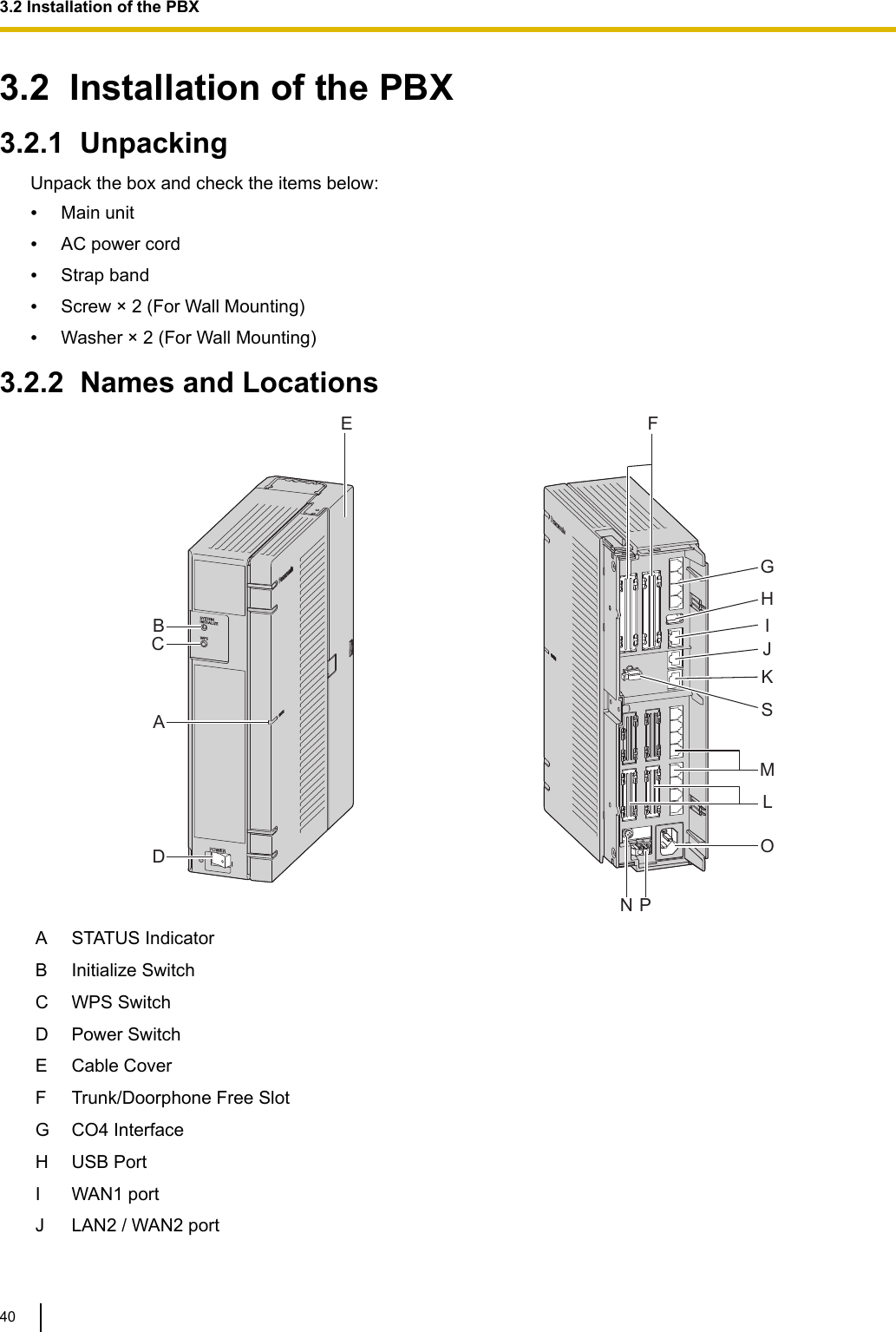
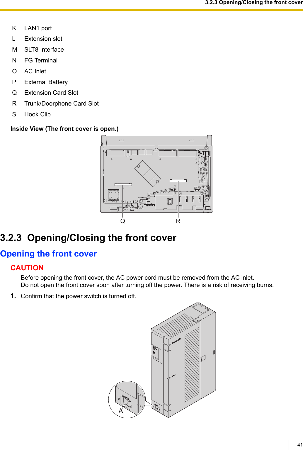
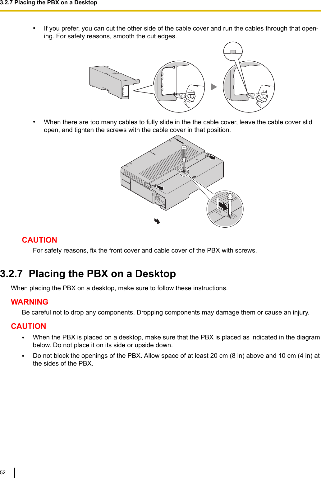
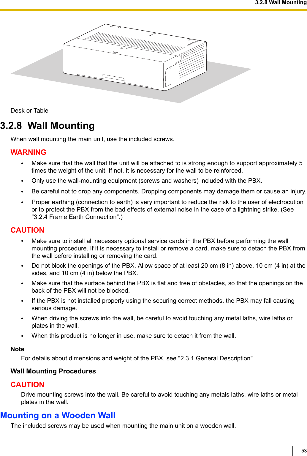
![3.1 Before Installation3.1.1 Before InstallationPlease read the following notes concerning installation and connection before installing the PBX and termi-nal equipment.Be sure to comply with all applicable laws, regulations, and guidelines.NoticePanasonic assumes no responsibility for injuries or property damage resulting from failures arising out ofimproper installation or operation inconsistent with this documentation.Safety Installation InstructionsWARNINGWhen installing telephone wiring, basic safety precautions should always be followed to reduce the riskof fire, electric shock and injury to persons, including the following:•Never install telephone wiring during a lightning storm.•Never install telephone jacks in wet locations unless the jack is specifically designed for wet loca-tions.•Never touch uninsulated telephone wires or terminals unless the telephone line has been disconnec-ted at the network interface.•Use caution when installing or modifying telephone lines.•Anti-static precautions should be taken during installation.Installation PrecautionsThe PBX can be mounted on a wall or placed on a desktop, and should be installed in an accessible loca-tion where it can be easily inspected and maintained.To prevent malfunction, noise, or discolouration, follow the instructions below:WARNINGDo not install the system in the following locations:•Areas where shocks or vibrations are frequent or strong. Such activity may lead to the product fallingover and causing injury, or may impair the product’s performance.•Areas with high amounts of dust. High amounts of dust can lead to fire or electric shock, and impairthe performance of the product.CAUTIONDo not install the system in the following locations:•In direct sunlight and hot, cold, or humid places. (Temperature range: 0 °C to 40 °C [32 °F to104 °F])•Areas where sulphuric gases may be present, such as near thermal springs.•Near devices that generate high frequencies, such as sewing machines or electric welders.•Locations where other objects will obstruct the area around the PBX. Be especially careful to leaveat least 5 cm (2 in) to the sides of the PBX for ventilation.•Locations where condensation can occur.NoticeDo not install the system in the following locations:3.1 Before Installation38](https://usermanual.wiki/Panasonic-of-North-America/96NKX-HTS824/User-Guide-2904004-Page-38.png)
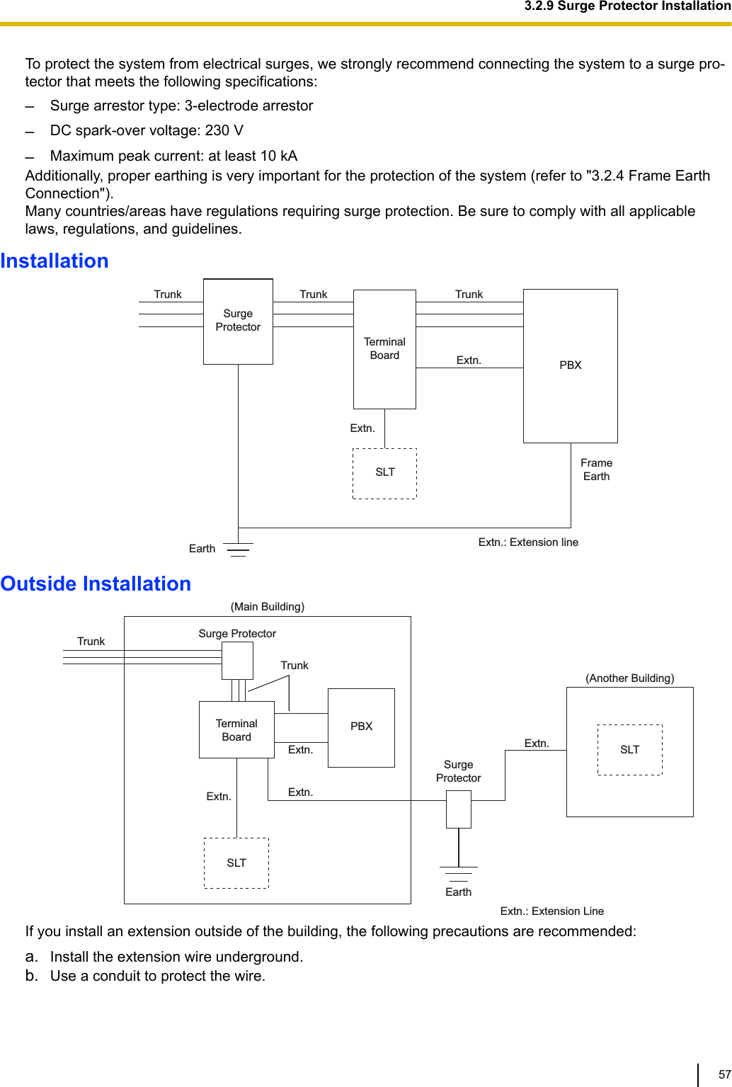
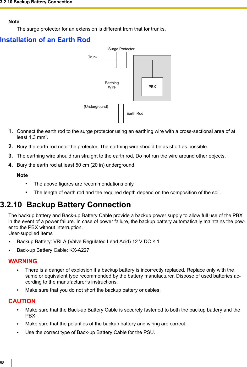
![•On or near computers, or other office equipment, as well as microwave ovens or air conditioners. (Itis preferable not to install the system in the same room as the above equipment.)•Within 1.8 m (6 ft) of radios and televisions. (Both the PBX and PTs should be at least 1.8 m [6 ft]away from such devices.)Do not perform the following:•Do not block the openings of the PBX.•Do not stack up the optional service cards.Wiring PrecautionsBe sure to follow these instructions when wiring the unit:CAUTION•Avoid using the same AC outlet for computers and other office equipment, as noise generated bysuch equipment may hamper system performance or interrupt the system.•Unplug the system from its power source when wiring, and plug the system back in only after all wir-ing is completed.•Trunks should be installed with surge protectors. For details, refer to "3.2.9 Surge Protector Installa-tion".Notice•Use 1-pair telephone cables when connecting SLTs, data terminals, answering machines, comput-ers, etc.•Mis-wiring may cause the PBX to operate improperly. Refer to "Installation" when wiring the system.•If an extension does not operate properly, disconnect the telephone from the extension line and con-nect it again, or turn off the PBX using the power switch, then turn it on again.•Use twisted pair cable for trunk connection.•To prevent signal noise from interfering with the performance of the product, do not run unshieldedtelephone cables near AC power cables, computer cables, AC power sources, etc. When runningcables near other noise-generating devices or cables, use shielded telephone cables or shield thetelephone cables with metal tubing.Preparing the Network EnvironmentBe sure to prepare your network’s environment for the installation of the PBX according to the intended PBXnetworking configuration.3.1.1 Before Installation39](https://usermanual.wiki/Panasonic-of-North-America/96NKX-HTS824/User-Guide-2904004-Page-39.png)
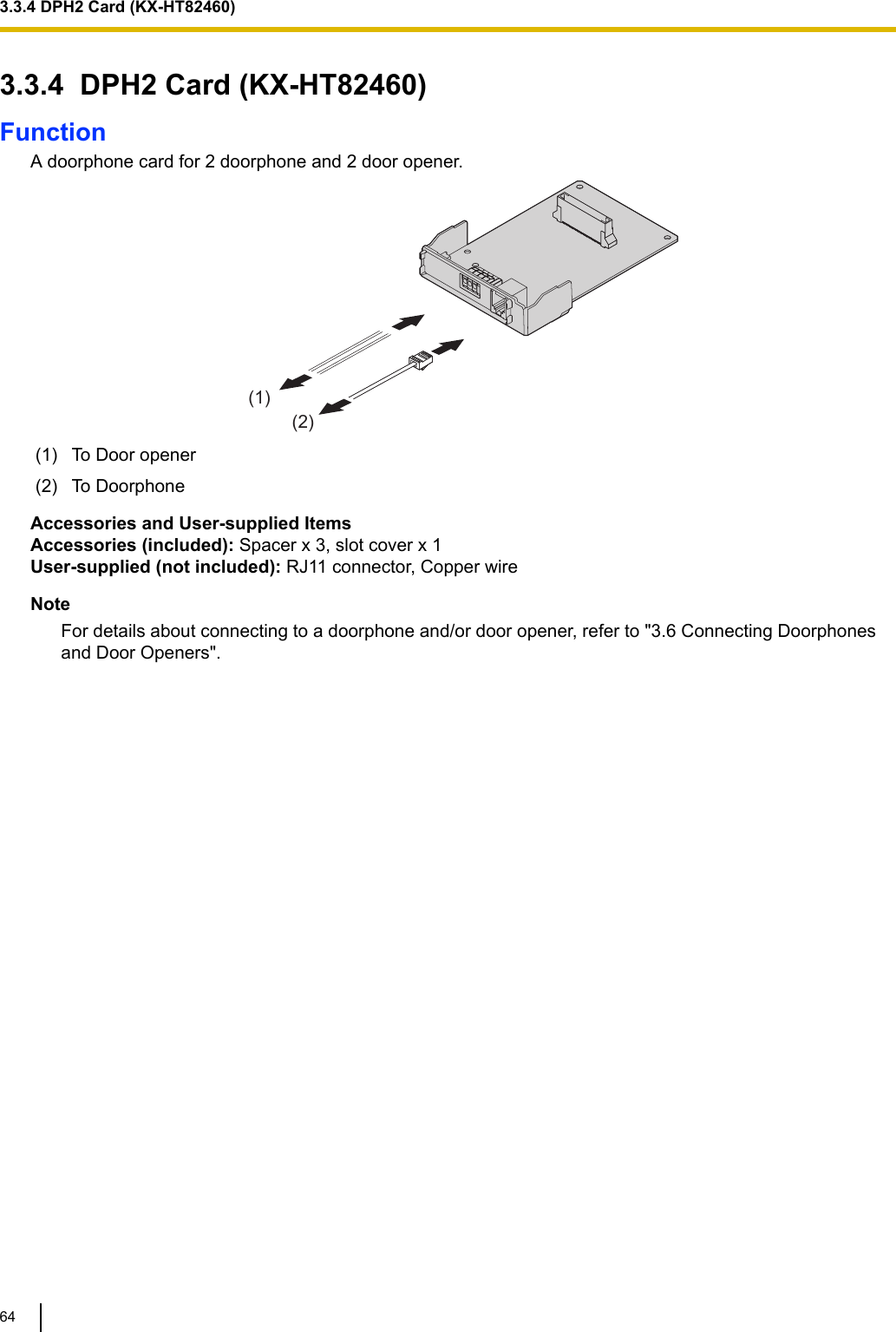
![3.3.2 LCOT4 Card (KX-HT82480)Function4 analogue trunk ports with Caller ID (FSK/FSK with Call Waiting Caller ID [Visual Caller ID]/DTMF).(1)AA RJ11(1) To trunkAccessories and User-supplied ItemsAccessories (included): Spacer x 3, slot cover x 1User-supplied (not included): RJ11 connector, Copper wireNote•Power failure Transfer feature between LCOT and SLC is not supported.•To confirm the trunk connection, refer to "Confirming the Trunk Connection" in "3.8 Starting thePBX".3.3.3 SLC8 Card (KX-HT82470)Function8-port extension card for SLTs with Caller ID (FSK), Message Waiting Lamp control.(1)AA RJ11(1) To ExtensionAccessories and User-supplied ItemsAccessories (included): Spacer x 3, slot cover x 1User-supplied (not included): RJ11 connector, Copper wireNote•Power failure Transfer feature between LCOT and SLC is not supported.3.3.2 LCOT4 Card (KX-HT82480)63](https://usermanual.wiki/Panasonic-of-North-America/96NKX-HTS824/User-Guide-2904004-Page-63.png)
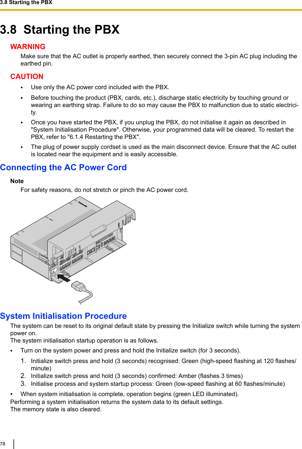
![CBAA Initialize switchB STATUS IndicatorC Power switchNote•After the PBX is initialised, you can restore system data to the PBX that has been backed up earlier.For details about backing up and restoring system data, refer to "Maintenance-[2-3]System Control-System Data Backup & Restore" in the Programming Item List." in the Programming Item List.•After the PBX is initialised, you must set up the mandatory settings required for the PBX with EasySetup Wizard. For details refer to "Connecting to Web Maintenance Console" and "3.9.4.1 Easy Set-up Wizard".•When a Backup Batteries is connected, make sure it is started as instructed in the documentation forthe Backup Batteries.Confirming the Trunk ConnectionAfter the PBX starts up, programme the PBX and connect trunks to the PBX.To confirm that the trunks are successfully connected, dial [*] [3] [7] + trunk number (3 digits) on an IP tele-phone, or press the IP telephone’s S-CO button. You will hear a dial tone if the trunk is available and con-nected.3.8 Starting the PBX79](https://usermanual.wiki/Panasonic-of-North-America/96NKX-HTS824/User-Guide-2904004-Page-79.png)
![3.10 Date and Time settingThe following items can be set for the date and time settings. For details about date and time settings, referto "PBX Configuration-[1-1]System-Date & Time-◆Date & Time" in the Programming Item List.•Automatic Time Adjustment•Daylight Saving Adjustment•Daylight Saving Time•Time Zone3.10 Date and Time setting84](https://usermanual.wiki/Panasonic-of-North-America/96NKX-HTS824/User-Guide-2904004-Page-84.png)
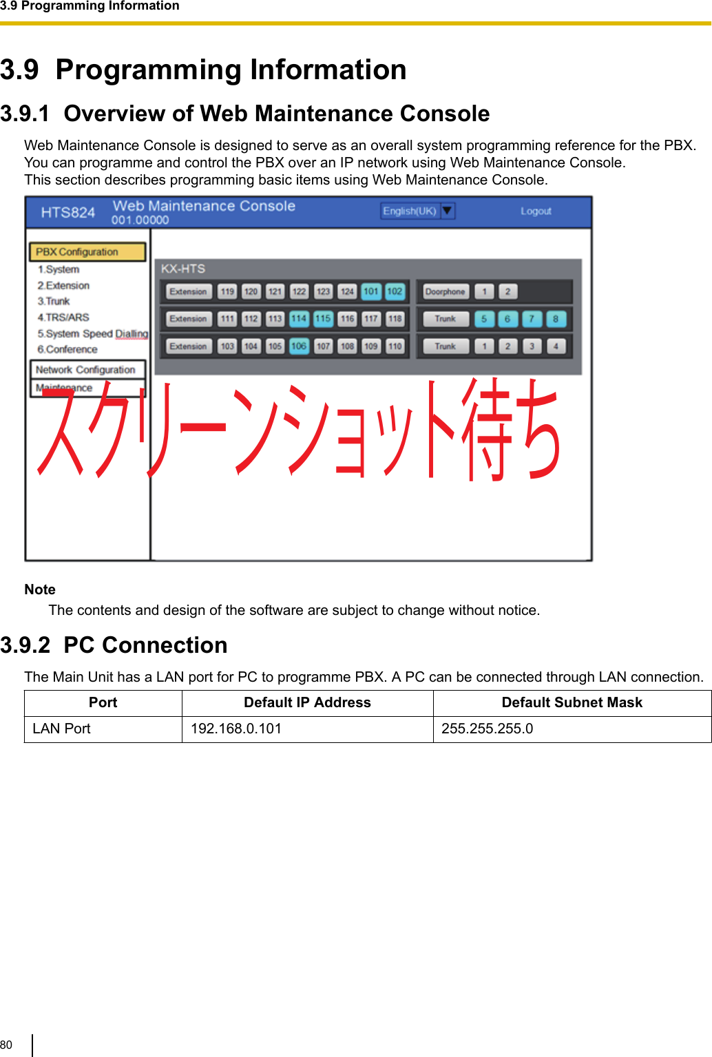
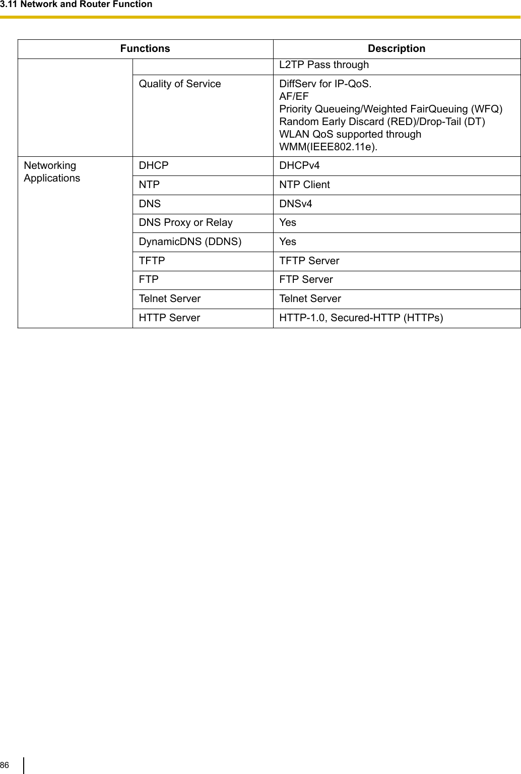
![3.11 Network and Router FunctionFollowing table describes networking functions and router functions. For details about data and time set-tings, refer to "2.1.1 PBX Configuration-[1-1]System-Date & Time" in the Programming Item List.Functions DescriptionWAN Interface 10/100/1000 Mbps EthernetLAN (Wired) Interface 10/100/1000 Mbps EthernetWireless LAN Interface IEEE 802.11b/g/nWLAN WEP64,WEP128/WPA/WPA2/MixedWPA/WPA2Automatic WLANChannel SelectionYesWLAN AssociationsFiltering (ACL)Yes (per SSID basis)WPS (Wi-Fi ProtectedSetup)YesLink Layer Protocols PPP Point-to-Point Protocol (PPP)PPP in HDLC-like FramingLink Control Protocol (LCP)Compression Control Protocol (CCP)PPP Internet Protocol Control Protocol (IPCP)PPP Authentication Protocols (PAP)PPP Challenge Handshake AuthenticationProtocol (CHAP)MS-CHAP v1/MS-CHAP v2PPP Encryption Control Protocol (ECP)PPPoEPPP Connection Keep AlivePPP DialOn DemandPPPoE relay from LAN Ethernet over WANEthernetBridging 802.1d LearningBridge and FilteringNetwork LayerProtocols IPv4 Networking Yes (IPv6 is not supported.)Multicast IGMPv3 & IGMPv2–Proxy–Snooping–HostNetwork CoreFunctions Static Routing YesFirewall Packet Filtering (IPv4, MAC address, portnumbers and protocols)Stateful Packet Inspection (SPI)DMZ hostBasic DoS Attack PreventionNAT/NAPT YesNATPass-through IPsec/IKE pass through3.11 Network and Router Function85](https://usermanual.wiki/Panasonic-of-North-America/96NKX-HTS824/User-Guide-2904004-Page-85.png)
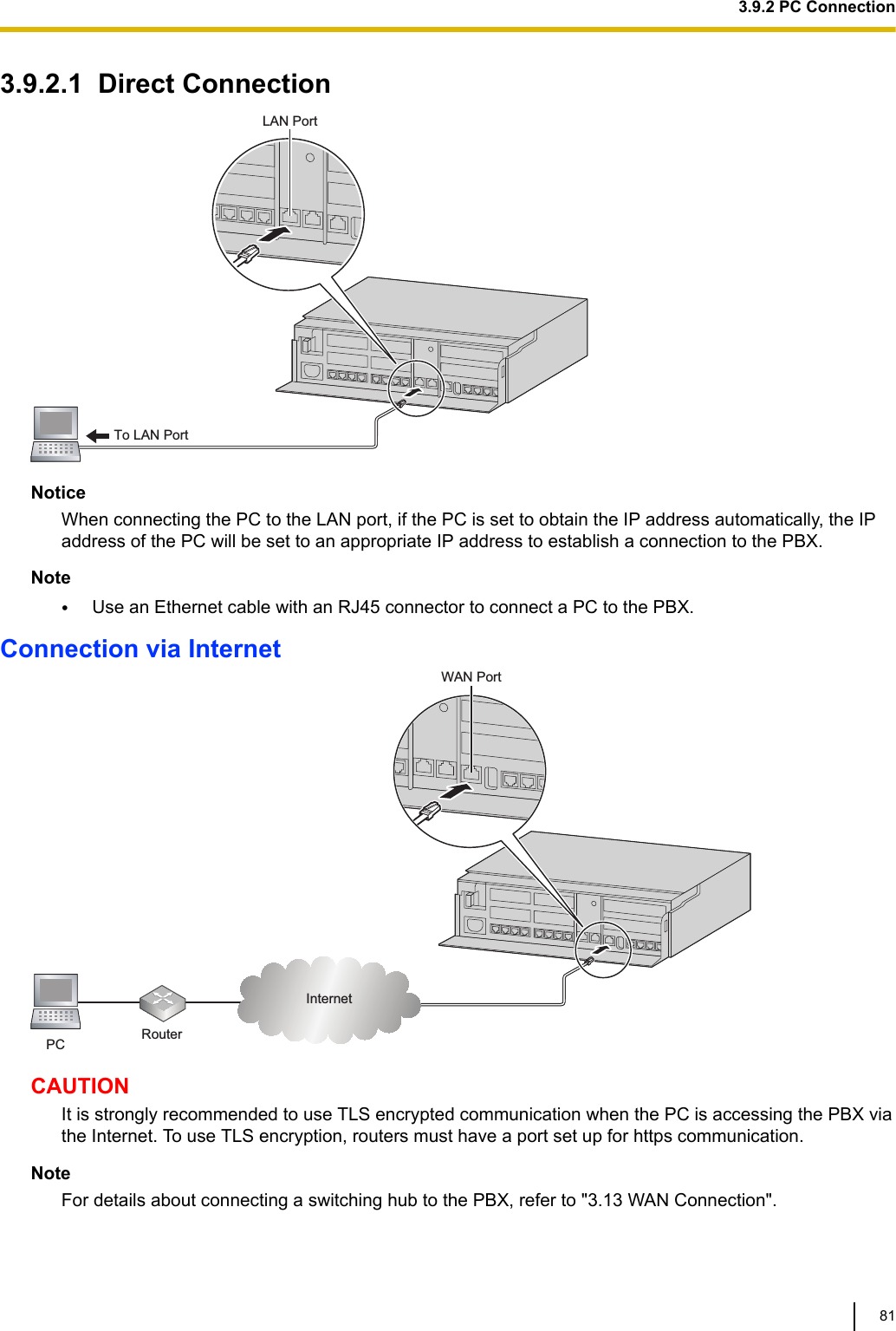
![3.13 WAN ConnectionDescriptionThe following protocols are supported for setting the IP address of the WAN interface.WAN Type DescriptionDynamic IP Address Retrieves an IP address dynamically from your service provider.Static IP Address Sets a static IP address.PPPoE Obtains an IP address dynamically from a PPPoE server.You can confirm the current connection status of the WAN interface in Web Maintenance Console.For details about the WAN Status, refer to "Network Configuration-[3-6]WAN Status" in the ProgrammingItem List.Conditions•If the protocol for setting the IP address is changed, you must perform a System Reset and restart thePBX before the setting can be applied.•When the built-in router is active, it serves as the default gateway on the LAN-side of the network. Thegateway address distributed by the DHCP feature will be changed to the LAN port’s IP address.•For details about what values to use for configuring the protocol for specifying an IP address, consult thenetwork administrator.3.13 WAN Connection90](https://usermanual.wiki/Panasonic-of-North-America/96NKX-HTS824/User-Guide-2904004-Page-90.png)
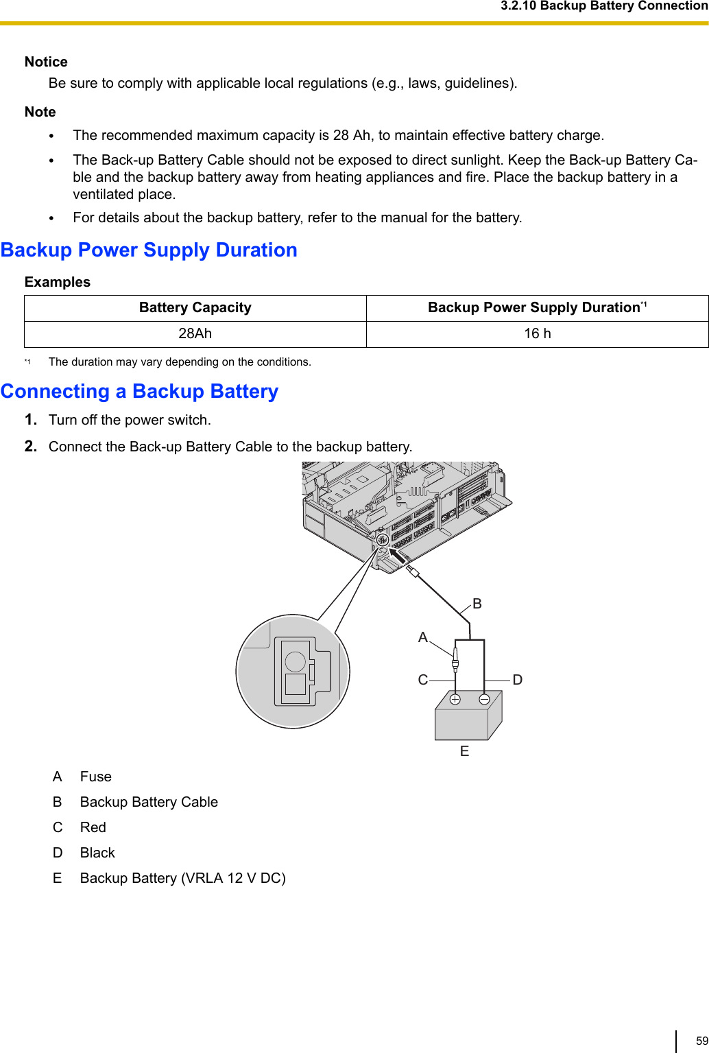
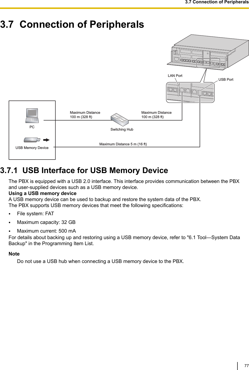
![5.1 System Data Backup and RestoreA PBX’s system data can be backed up to a USB memory device inserted into the PBX’s USB port or to aPC in the PBX’s LAN network. At a later time, the backed up data can be restored to the PBX. To back up the system data to a USB memory device•Insert a USB memory device into the USB port of the PBX.•For details about backing up the system data to a USB memory device, refer to "Maintenance-[2-3]Sys-tem Control-System Data Backup-◆System Data Backup" in the Programming Item List.Note•The USB memory device must be compatible for use with the PBX. For details, refer to"3.7 Connection of Peripherals". Restoring backed up data from a USB memory device to a PBX•For details about restoring backed up data stored on a USB memory, refer to "Maintenance-[2-3]SystemControl-System Data Backup-◆System Data Restore" in the Programming Item List.Note•Data cannot be restored in the following cases.–The USB memory device hardware is faulty.–The data on the USB memory device has become corrupted.–The USB memory device is removed from the USB port of the PBX during the restorationprocess.•After a system data restore, the main unit must be restarted using the Web Maintenance Con-sole. To back up the system data to a PC•For details about backing up the system data to a PC, refer to "Maintenance-[2-3]System Control-Sys-tem Data Backup-◆System Data Backup" in the Programming Item List.Restoring backed up data from a PC to a PBX•For details about restoring backed up data stored on a PC, refer to "Maintenance-[2-3]System Control-System Data Backup-◆System Data Restore" in the Programming Item List.Note•After a system data restore, the main unit must be restarted using the Web Maintenance Con-sole. Regular Automatic Backup FeatureThe PBX regularly backs up the system data every 30 minutes.The backup file is saved in the "Panasonic" folder in the internal memory of the main unit.5.1 System Data Backup and Restore94](https://usermanual.wiki/Panasonic-of-North-America/96NKX-HTS824/User-Guide-2904004-Page-94.png)
![5.2 Software UpgradingObtaining software updates (downloading the update to the PBX) can be done manually via Web Mainte-nance Console. In this case, software updates can be obtained from a USB memory device connected tothe PBX, or a PC that can access Web Maintenance Console.Installing an update can be done either manually via Web Maintenance Console, or on a set schedule.The software of the following types of devices and components can be updated:Data Type DescriptionMain software data Operating system data area on the PBX’s mother board.SIP extension software data*1 Firmware of supported SIP extensions*1 Only Panasonic telephones are supported. For details about a specific telephone, refer to the telephone's documentation.Note•The software version of the mother board can be confirmed through system programming.•For details, refer to "Maintenance-[2-1]System Control-Firmware Transfer to PBX" in the Program-ming Item List.•For details, refer to "Maintenance-[2-2]System Control-Firmware Update to PBX" in the Program-ming Item List.5.2 Software Upgrading95](https://usermanual.wiki/Panasonic-of-North-America/96NKX-HTS824/User-Guide-2904004-Page-95.png)
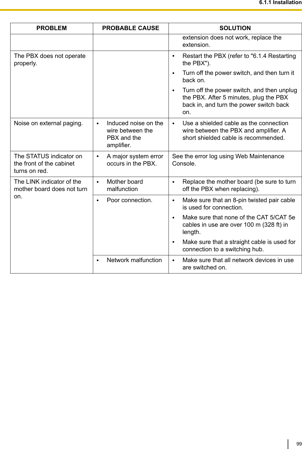
![6.1.4 Restarting the PBXIf the PBX does not operate properly, restart the PBX using Web Maintenance Console. Before restartingthe PBX, try the system feature again to confirm whether there definitely is a problem or not.Note•Restarting the PBX causes the following:–Camp-on is cleared.–Calls on hold are terminated.–Calls on exclusive hold are terminated.–Calls in progress are terminated.–Call park is cleared.Other data stored in memory, except the above, are not cleared.OperationFor details about DHCP server setting, refer to "Maintenance-[4-2]System Reset-◆System Reset" in theProgramming Item List.6.1.4 Restarting the PBX102](https://usermanual.wiki/Panasonic-of-North-America/96NKX-HTS824/User-Guide-2904004-Page-102.png)
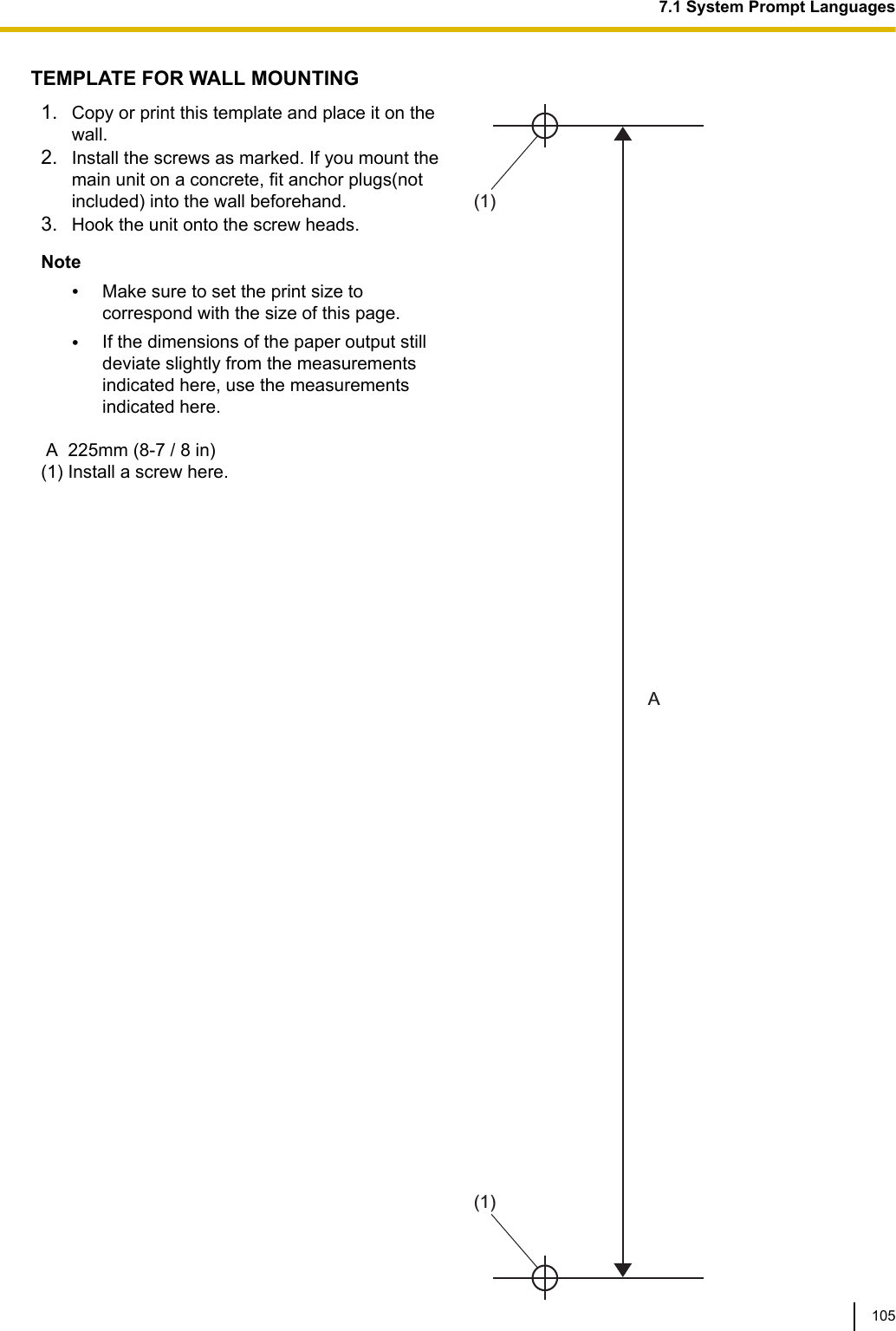
![7.1 System Prompt LanguagesNote•The following abbreviations are used in the language file names:–UK: United Kingdom–US: United States–LA: Latin America–CA: Canada–BR: Brazil•No. 1 is set by default. For details, see "PBX Configuration-[1-6]System Options- ◆Prompt Language" inthe Programming Item List.System prompt languages stored in the System MemoryKX-HTSSeriesSuffixAG AL BR HK US MLNo.1(Primary)LA-Spanish UK-English BR-PortugueseUS-English US-English US-EnglishNo.2 US-English US-English Mandarin LA-Spanish MandarinNo.3 TaiwanMandarin TaiwanMandarinNo.4 Cantonese CantoneseNo.5 No.1 (Primary) NZ RU SA BXNo.1(Primary)UK-English Russian UK-English US-EnglishNo.2 Ukrainian LA-SpanishNo.3 US-EnglishNo.4No.57.1 System Prompt Languages104](https://usermanual.wiki/Panasonic-of-North-America/96NKX-HTS824/User-Guide-2904004-Page-104.png)