Panasonic of North America 96NKX-HTS824 Hybrid IP-PBX User Manual
Panasonic Corporation of North America Hybrid IP-PBX Users Manual
Users Manual
Getting Started
Hybrid IP-PBX
Model No. KX-HTS824
KX-HTS32
Thank you for purchasing this Panasonic product.
Please read this manual carefully before using this product and save this manual for future use.
In particular, be sure to read "1.1 For Your Safety, page 8" before using this product.
KX-HTS: Series (KX-HTS824 KX-HTS32) : PJMPR Software File Version 001.00000 or later
Manuals and supporting information are provided on the Panasonic Web site at:
http://www.panasonic.net/pcc/support/pbx/

System Components
System Components for KX-HTS Series
Category Model No. Description
Main Unit KX-HTS824
KX-HTS32
Main Unit
Physical Cards KX-HT82480 4 ports Analogue Trunk interface with Caller ID
(LCOT4)
KX-HT82470 8 ports Standard Telephone Line Interface with Caller
ID (SLC8)
KX-HT82460 2 ports Panasonic Proprietary Door phone Interface
with door opener (no sensor interface) (DPH2)
Proprietary Equipment KX-A227 Backup battery cable
Equipment Compatibility for Main Unit
The PBX supports the following equipment:
Doorphones
•Doorphone (KX-T30865, KX-T7765)
SIP Phones
•Refer to the Panasonic Web site for information on compatible terminals.
Other
•Single line telephones
Note
•For the equipment that can be connected to a particular telephone, refer to the telephone's manual.
Notice
•This PBX supports SIP extensions. However, some PBX features may not be available depending on
the type of telephone.
•Under power failure conditions, the connected telephones may not operate. Please ensure that a sepa-
rate telephone, not dependent on local power, is available for emergency use.
•Prior to connection of this product, please verify that the intended operating environment is supported.
Satisfactory performance cannot be guaranteed for the following:
–interoperability and compatibility with all devices and systems connected to this product
–proper operation and compatibility with services provided by telecommunications companies over
connected networks
Note
•Some optional hardware, software, and features are not available in some countries/areas. Please
consult your certified Panasonic dealer for more information.
•In this manual, the suffix of each model number (e.g., KX-HTS824BX) is omitted unless necessary.
List of Abbreviations
•SIP Extension -> Extensions of the PBX which use Session Initiation Protocol for communication.
•SLT -> Single Line Telephone
System Components
2

•P-SIP -> Panasonic SIP Phones (KX-HDV series)
System Components
3

Introduction
This Manual is designed to serve as an overall technical reference for the Panasonic KX-HTS824 and
KX-HTS32 IP-PBXs. It provides instructions for installing the hardware, and programming the PBX using
Web Based programming.
The Structure of this Manual
This manual contains the following sections:
Section 1 Safety Precautions
Provides important information intended to prevent personal injury and property damage.
Section 2 System Outline
Provides general information on the PBX, including the system capacity and specifications.
Section 3 Installation
Describes the procedures to install the PBX. Detailed instructions for planning the installation site, op-
tional service cards, and cabling of peripheral equipment are provided.
Section 4 Confirming Connections
Making and receiving calls with extensions and trunks.
Section 5 Maintenance
Maintenance procedures.
Section 6 Troubleshooting
Provides information on the PBX and telephone troubleshooting.
Section 7 Appendix
Provides information about System Prompt Languages and the revision history.
About the Other Manuals
In addition to this Manual, the following manuals are available:
Programming Item List (PI)
Provides step-by-step instructions for performing system programming using a PC.
Feature Manual (FM)
Describes all basic, optional and programmable features of the PBX.
About the software version of your PBX
The contents of this manual apply to PBXs with a certain software version, as indicated on the cover of this
manual. To confirm the software version of your PBX, see "Maintenance-Version Information" in the Pro-
gramming Item List.
Trademarks
•Microsoft is a registered trademark or trademark of Microsoft Corporation in the United States and/or
other countries.
•All other trademarks identified herein are the property of their respective owners.
•Microsoft product screen shot(s) reprinted with permission from Microsoft Corporation.
Introduction
4

Table of Contents
1 Safety Precautions ................................................................................. 7
1.1 For Your Safety ................................................................................................................ 8
1.2 Important Safety Instructions ...................................................................................... 15
1.3 Precautions .................................................................................................................... 16
1.4 Data Security ................................................................................................................. 19
1.5 F.C.C. REQUIREMENTS AND RELEVANT INFORMATION ......................................... 19
2 System Outline ..................................................................................... 23
2.1 Basic System Construction .......................................................................................... 24
2.1.1 System Configurations ................................................................................................. 24
2.1.2 System Connection Diagram ........................................................................................ 25
2.1.3 Block Diagram .............................................................................................................. 26
2.1.4 Typical Network Setting Example ................................................................................. 27
2.2 Optional Equipment ...................................................................................................... 31
2.2.1 Optional Equipment ...................................................................................................... 31
2.3 Specifications ................................................................................................................ 32
2.3.1 General Description ...................................................................................................... 32
2.3.2 Characteristics .............................................................................................................. 33
2.3.3 System Capacity ........................................................................................................... 33
3 Installation ............................................................................................. 37
3.1 Before Installation ......................................................................................................... 38
3.1.1 Before Installation ......................................................................................................... 38
3.2 Installation of the PBX .................................................................................................. 40
3.2.1 Unpacking ..................................................................................................................... 40
3.2.2 Names and Locations ................................................................................................... 40
3.2.3 Opening/Closing the front cover ................................................................................... 41
3.2.3.1 Removing/Attaching the Cable Cover ........................................................................ 44
3.2.4 Frame Earth Connection .............................................................................................. 44
3.2.5 Installing/Removing the Optional Service Cards .......................................................... 45
3.2.5.1 Slot covers ................................................................................................................. 49
3.2.6 Securing the Cables ..................................................................................................... 50
3.2.7 Placing the PBX on a Desktop ..................................................................................... 52
3.2.8 Wall Mounting ............................................................................................................... 53
3.2.9 Surge Protector Installation .......................................................................................... 56
3.2.10 Backup Battery Connection .......................................................................................... 58
3.3 The Mother Board and Option Cards .......................................................................... 60
3.3.1 Mother Board ................................................................................................................ 60
3.3.2 LCOT4 Card (KX-HT82480) ......................................................................................... 63
3.3.3 SLC8 Card (KX-HT82470) ............................................................................................ 63
3.3.4 DPH2 Card (KX-HT82460) ........................................................................................... 64
3.4 Connecting Outside Trunks ......................................................................................... 65
3.4.1 Connecting SIP Trunks ................................................................................................. 65
3.4.2 Connecting Analogue Trunks ....................................................................................... 67
3.5 Connecting Extensions ................................................................................................ 68
3.5.1 Connecting SIP Extensions .......................................................................................... 68
3.5.2 LAN Connections for IP Telephones ............................................................................. 70
3.5.3 Connecting Analogue Extensions Maximum Cabling Distances of the Extension Wiring
(Twisted Cable) ............................................................................................................. 72
3.6 Connecting Doorphones and Door Openers .............................................................. 73
3.7 Connection of Peripherals ............................................................................................ 77
3.7.1 USB Interface for USB Memory Device ........................................................................ 77
Table of Contents
5

3.8 Starting the PBX ............................................................................................................ 78
3.9 Programming Information ............................................................................................ 80
3.9.1 Overview of Web Maintenance Console ...................................................................... 80
3.9.2 PC Connection ............................................................................................................. 80
3.9.2.1 Direct Connection ...................................................................................................... 81
3.9.3 Starting Web Maintenance Console ............................................................................. 82
3.9.4 Programming the PBX .................................................................................................. 83
3.9.4.1 Easy Setup Wizard .................................................................................................... 83
3.10 Date and Time setting ................................................................................................... 84
3.11 Network and Router Function ...................................................................................... 85
3.12 LAN Connection ............................................................................................................ 87
3.12.1 Wired LAN Connection ................................................................................................. 87
3.12.2 Wireless LAN Connection ............................................................................................. 88
3.13 WAN Connection ........................................................................................................... 90
4 Confirming Connections ...................................................................... 91
4.1 Making and Receiving Calls ......................................................................................... 92
4.1.1 Calling Another Extension ............................................................................................ 92
4.1.2 Calling an Outside Party ............................................................................................... 92
4.1.3 Answering Calls ............................................................................................................ 92
5 Maintenance .......................................................................................... 93
5.1 System Data Backup and Restore ............................................................................... 94
5.2 Software Upgrading ...................................................................................................... 95
5.3 System Initialisation Procedure ................................................................................... 96
6 Troubleshooting ................................................................................... 97
6.1 Troubleshooting ............................................................................................................ 98
6.1.1 Installation .................................................................................................................... 98
6.1.2 Connection ................................................................................................................. 100
6.1.3 Operation .................................................................................................................... 100
6.1.4 Restarting the PBX ..................................................................................................... 102
7 Appendix ............................................................................................. 103
7.1 System Prompt Languages ........................................................................................ 104
Table of Contents
6

Section 1
Safety Precautions
This section provides important information intended to
prevent personal injury and property damage.
7
1.1 For Your Safety
To prevent personal injury and/or damage to property, be sure to observe the following safety precautions.
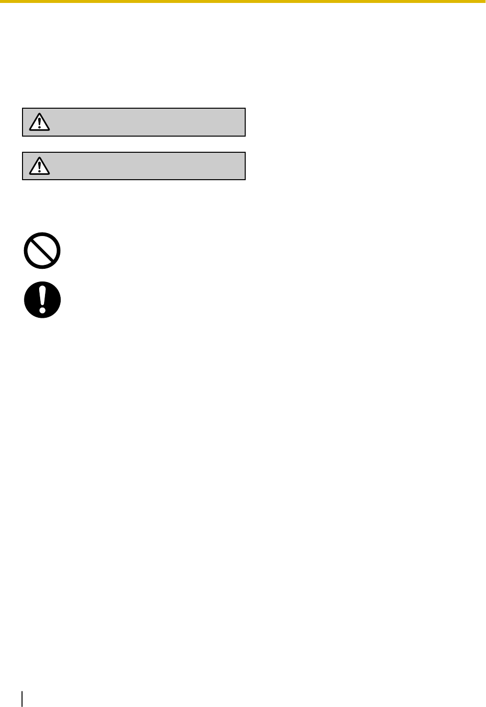
The following symbols classify and describe the level of hazard and injury caused when this unit is
operated or handled improperly.
WARNING
This notice means that misuse could result in death
or serious injury.
CAUTION
This notice means that misuse could result in injury
or damage to property.
The following types of symbols are used to classify and describe the type of instructions to be ob-
served.
This symbol is used to alert users to a specific operating procedure that must not be
performed.
This symbol is used to alert users to a specific operating procedure that must be followed in
order to operate the unit safely.
Notice
Panasonic assumes no responsibility for injuries or property damage resulting from failures arising out of
improper installation or operation inconsistent with this documentation.
1.1 For Your Safety
8

WARNING
For All Telephone Equipment
•Do not install the product in any other way than described in relevant manuals.
•Do not install the product in a place exposed to rain or moisture, or a place where water, oil, or other
liquids can drip or splash onto on the product. Such conditions can lead to fire or electric shock, and
may impair the performance of the product.
•Do not install the system in the following locations:
a. Areas where shocks or vibrations are frequent or strong. Such activity may lead to the product falling
over and causing injury, or may impair the product’s performance.
b. Areas with high amounts of dust. High amounts of dust can lead to fire or electric shock, and impair
the performance of the product.
•Do not place the product on an unstable or uneven surface. If the product were to fall over, it may cause
injury or damage to the product.
•Do not supply power to a combination of devices that exceeds the total rated capacity of the wall outlets
or extension cables used. If outlets, power strips, extension cords, etc. are used in a manner that ex-
ceeds their rated capacity, they emit large amounts of heat, which could cause a fire.
•The product must only be installed and serviced by qualified service personnel. The product should be
used as-is from the time of purchase; it should not be disassembled or modified. Disassembly or modifi-
cation can cause a fire, electric shock, or damage to the product.
•Follow all warnings and instructions marked on the product.
•Small objects, such as the screws, pose a choking hazard. Keep small objects out of reach of children.
•Products that require a power source should only be connected to the type of electrical power supply
specified on the product label. If you are not sure of the type of power supply to your office/home, con-
sult your dealer or local power company.
•For safety purposes some products are equipped with an earthed plug. If you do not have an earthed
outlet, please have one installed. Do not bypass this safety feature by tampering with the plug.
•When installing telephone wiring, basic safety precautions should always be followed to reduce the risk
of fire, electric shock and injury to persons, including the following:
a. Never install telephone wiring during a lightning storm.
b. Never install telephone jacks in wet locations unless the jack is specifically designed for wet loca-
tions.
c. Never touch uninsulated telephone wires or terminals unless the telephone line has been disconnec-
ted at the network interface.
d. Use caution when installing or modifying telephone lines.
e. Anti-static precautions should be taken during installation.
•Unplug the product from the wall outlet and have it serviced by qualified service personnel in the follow-
ing cases:
a. When the power supply cord or plug is damaged or frayed.
1.1 For Your Safety
9

b. If liquid has been spilled into the product.
c. If the product has been exposed to rain or water.
d. If the product does not operate according to the operating instructions. Adjust only the controls that
are explained in the operating instructions. Improper adjustment of other controls may result in dam-
age and may require service by a qualified technician to restore the product to normal operation.
e. If the product has been dropped or the cabinet has been damaged.
f. If product performance deteriorates.
For the PBX
•Do not insert foreign objects of any kind into this product, as they may touch dangerous voltage points or
short out parts that could result in a fire or electric shock.
•Do not pull, bend, rest objects on, or chafe the power cord and plug. Damage to the power cord or plug
can cause fire or electric shock.
•Do not attempt to repair the power cord or plug. If the power cord or plug is damaged or frayed, contact
an authorised Panasonic Factory Service Centre for a replacement.
•Do not use the product in health care facilities if any regulations posted in the area instruct you not to do
so. Hospitals or health care facilities may be using devices sensitive to external RF (radio frequency)
energy.
•Do not leave the slot open if an option service card is not installed after removing a dummy cover plate.
Make sure to insert the slot cover included with the option service card into the slot.
•If damage to the unit exposes any internal parts, disconnect the power supply cord immediately and re-
turn the unit to your dealer.
•To prevent fires, electric shock, injury, or damage to the product, be sure to follow these guidelines when
performing any wiring or cabling:
a. Before performing any wiring or cabling, unplug the product's power cord from the outlet. After com-
pleting all wiring and cabling, plug the power cord back into the outlet.
b. When laying cables, do not bundle the product's power cord with the power cords of other devices.
c. Do not place any objects on top of the cables connected to the PBX.
d. When running cables along the floor, use protectors to prevent the cables from being stepped on.
e. Do not run any cables under carpeting.
•Unplug this unit from the AC outlet if it emits smoke, an abnormal smell or makes unusual noise. These
conditions can cause fire or electric shock. Confirm that smoke has stopped and contact an authorised
Panasonic Factory Service Centre.
•Make sure that the wall that the unit will be attached to is made of concrete or thick wood, and is strong
enough to support the unit (approx. 11 kg [24 lb]). Do not attach the unit to walls made from plasterboard
or thin plywood. Attaching the unit to areas where there are strong winds, or where shocks or vibrations
are frequent or strong, may lead to the product falling over.
•Only use the wall-mounting equipment (screws and washers) included with the PBX.
•The earthing wire of the AC cable has an effect against external noise and lightning strikes, but it may
not be enough to protect the PBX and to ensure electromagnetic compatibility. A permanent connection
between earth and the earth terminal of the PBX must be made.
1.1 For Your Safety
10

•Proper earthing (connection to earth) is very important to reduce the risk to the user of electrocution or
to protect the PBX from the bad effects of external noise in the case of a lightning strike. (See
"3.2.4 Frame Earth Connection".)
•Plug the power cord firmly into an AC outlet. Otherwise, it can cause fire or electric shock.
•Be careful not to drop any components. Dropping components may damage them or cause an injury.
•Make sure that the AC outlet is properly earthed, then securely connect the 3-pin AC plug including the
earthed pin.
•A lithium battery is used in the main unit. There is a risk of explosion if the battery is replaced with an
incorrect type. Dispose of used batteries according to the manufacturer’s instructions.
•Consult the manufacturer of any personal medical devices, such as pacemakers or hearing aids, to de-
termine if they are adequately shielded from external RF (radio frequency) energy.
–For North America / Latin America / Taiwan:
Wi-Fi features operate between 2.412 GHz and 2.462 GHz with a peak transmission power of 100
mW.
–For all other countries / areas:
Wi-Fi features operate between 2.412 GHz and 2.472 GHz with a peak transmission power of 100
mW.
1.1 For Your Safety
11

CAUTION
For All Telephone Equipment
•The product should be kept free of dust, moisture, high temperature (more than 40 °C [104 °F]) and vi-
bration, and should not be exposed to direct sunlight.
•Unplug the product from the wall outlet before cleaning. Wipe the product with a soft cloth. Do not clean
with abrasive powders or with chemical agents such as benzine or thinner. Do not use liquid cleaners or
aerosol cleaners.
For the PBX
•Do not install the system in the following locations:
a. In direct sunlight and hot, cold, or humid places. (Temperature range: 0 °C to 40 °C [32 °F to
104 °F])
b. Areas where sulphuric gases may be present, such as near thermal springs.
c. Near devices that generate high frequencies, such as sewing machines or electric welders.
d. Locations where other objects will obstruct the area around the PBX. Be especially careful to leave
at least 5 cm (2 in) to the sides of the PBX for ventilation.
e. Locations where condensation can occur.
•Do not block the openings of the PBX. Allow space of at least 20 cm (8 in) above, 10 cm (4 in) at the
sides, and 10 cm (4 in) below the PBX.
•When installing or removing the optional service cards, do not put pressure on any parts of the mother
board. Doing so may result in damage to the PBX.
•Once you have started the PBX, if you unplug the PBX, do not initialise it again as described in "System
Initialisation Procedure". Otherwise, your programmed data will be cleared. To restart the PBX, refer to
"6.1.4 Restarting the PBX".
•Before touching the product (PBX, cards, etc.), discharge static electricity by touching ground or wearing
an earthing strap. Failure to do so may cause the PBX to malfunction due to static electricity.
•When relocating the equipment, first disconnect the telecom connection before disconnecting the power
connection. When the unit is installed in the new location, reconnect the power first, and then reconnect
the telecom connection.
•The plug of power supply cordset is used as the main disconnect device. Ensure that the AC outlet is
located near the equipment and is easily accessible.
•Slots and openings in the front, back and bottom of the cabinet are provided for ventilation; to protect it
from overheating, these openings must not be blocked or covered. The openings should never be
blocked by placing the product on a bed, sofa, rug, or other similar surface while in use. The product
should never be placed near or over a radiator or other heat source. This product should not be placed
in a sealed environment unless proper ventilation is provided.
1.1 For Your Safety
12

•Make sure that the surface behind the PBX is flat and free of obstacles, so that the openings on the
back of the PBX will not be blocked.
•When this product is no longer in use, make sure to detach it from the wall.
•Use only the AC power cord included with the PBX. A certified power supply cord has to be used with
this equipment. The relevant national installation and/or equipment regulations shall be considered. A
certified power supply cord not lighter than ordinary polyvinyl chloride flexible cord according to IEC
60227 (designation H05VV-F 3G 0.75 mm2) shall be used.
•Make sure to install all necessary optional service cards in the PBX before performing the wall mounting
procedure. If it is necessary to install or remove a card, make sure to detach the PBX from the wall be-
fore installing or removing the card.
•When driving the screws into the wall, be careful to avoid touching any metal laths, wire laths or plates in
the wall.
•Before opening the front cover, the AC power cord must be removed from the AC inlet.
•Disconnect the AC power source before servicing the equipment.
•Do not open the front cover soon after turning off the power. There is a risk of receiving burns.
•For safety reasons, fix the front cover and cable cover of the PBX with screws.
•If the PBX is not installed properly using the securing correct methods, the PBX may fall causing serious
damage.
•When the PBX is placed on a desktop, make sure that the PBX is placed as indicated in "3.2.7 Placing
the PBX on a Desktop". Do not place it on its side or upside down.
•Performing surge protection is essential. Make sure to follow the instructions in "3.2.9 Surge Protector
Installation".
•It is strongly recommended to use TLS encrypted communication when the PC is accessing the PBX via
the Internet. To use TLS encryption, routers must have a port set up for https communication.
•Avoid using the same AC outlet for computers and other office equipment, as noise generated by such
equipment may hamper system performance or interrupt the system.
•Unplug the system from its power source when wiring, and plug the system back in only after all wiring is
completed.
•Trunks should be installed with surge protectors. For details, refer to "3.2.9 Surge Protector Installation".
•When installing or removing the optional service cards, the power switch must be turned off, and the AC
power cord must be removed from the AC inlet.
•For earthing wire, green-and-yellow insulation is required, and the cross-sectional area of the conductor
must be more than 0.75 mm2 or 18 AWG.
Notice
For All Telephone Equipment
•Read and understand all instructions.
For the PBX
•Keep the unit away from heating appliances and devices that generate electrical noise such as fluo-
rescent lamps, motors and televisions. These noise sources can interfere with the performance of
the PBX.
•If you are having problems making calls to outside destinations, follow this procedure to test the
trunks:
a. Disconnect the PBX from all trunks.
b. Connect known working SLTs to those trunks.
1.1 For Your Safety
13

c. Make a call to an external destination using those SLTs.
If a call cannot be carried out correctly, there may be a problem with the trunk that the SLT is con-
nected to. Contact your telephone company.
If all SLTs operate properly, there may be a problem with your PBX. Do not reconnect the PBX to the
trunks until it has been serviced by an authorised Panasonic Factory Service Centre.
1.1 For Your Safety
14

1.2 Important Safety Instructions
When using your telephone equipment, basic safety precautions should always be followed to reduce the
risk of fire, electric shock and injury to persons, including the following:
•Do not use the product near water, for example, near a bathtub, wash bowl, kitchen sink, or laundry tub,
in a wet basement, or near a swimming pool.
•Avoid using wired telephones during an electrical storm. There is a remote risk of electric shock from
lightning.
•Do not use a telephone in the vicinity of a gas leak to report the leak.
SAVE THESE INSTRUCTIONS
1.2 Important Safety Instructions
15
1.3 Precautions
For users in the European Union only
Information for Users on Collection and Disposal of Old Equipment and used Batteries
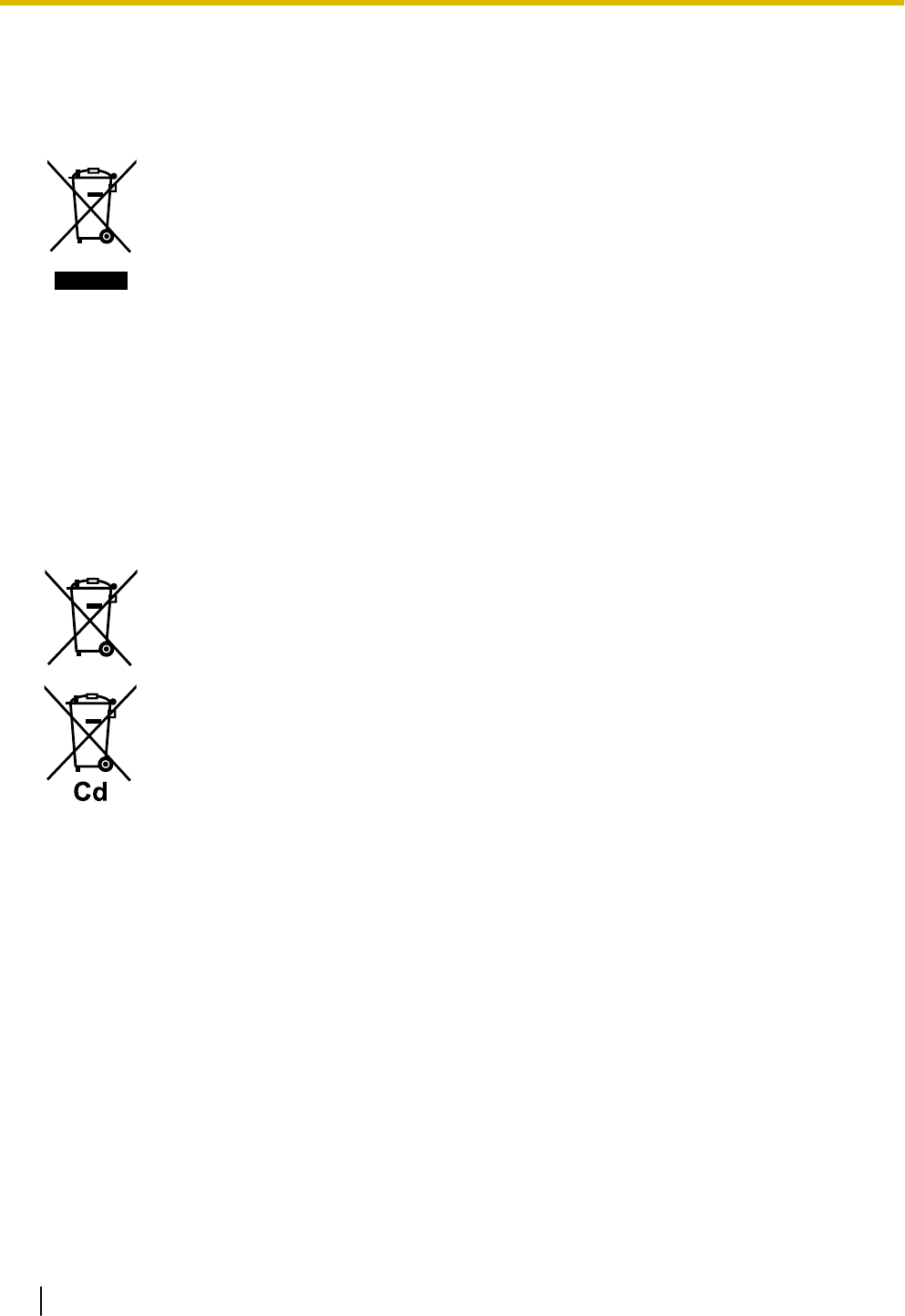
These symbols on the products, packaging, and/or accompanying documents
mean that used electrical and electronic products and batteries should not be
mixed with general household waste.
For proper treatment, recovery and recycling of old products and used batteries,
please take them to applicable collection points, in accordance with your national
legislation and the Directives 2002/96/EC and 2006/66/EC.
By disposing of these products and batteries correctly, you will help to save
valuable resources and prevent any potential negative effects on human health
and the environment which could otherwise arise from inappropriate waste
handling.
For more information about collection and recycling of old products and batteries,
please contact your local municipality, your waste disposal service or the point of
sale where you purchased the items.
Penalties may be applicable for incorrect disposal of this waste, in accordance
with national legislation.
For business users in the European Union
If you wish to discard electrical and electronic equipment, please contact your
dealer or supplier for further information.
Information on Disposal in other Countries outside the European Union
These symbols are only valid in the European Union. If you wish to discard these
items, please contact your local authorities or dealer and ask for the correct
method of disposal.
Note for the battery symbol (bottom two symbol examples):
This symbol might be used in combination with a chemical symbol. In this case it
complies with the requirement set by the Directive for the chemical involved.
For users in New Zealand only
•This equipment shall not be set to make automatic calls to the Telecom ‘111’ Emergency Service.
•The grant of a Telepermit for any item of terminal equipment indicates only that Telecom has accepted
that the item complies with minimum conditions for connection to its network. It indicates no endorse-
ment of the product by Telecom, nor does it provide any sort of warranty. Above all, it provides no assur-
ance that any item will work correctly in all respects with another item of Telepermitted equipment of a
different make or model, nor does it imply that any product is compatible with all of Telecom’s network
services.
•This equipment is not capable, under all operating conditions, of correct operation at the higher speeds
for which it is designed. Telecom will accept no responsibility should difficulties arise in such circumstan-
ces.
•Some parameters required for compliance with Telecom’s Telepermit requirements are dependent on
the equipment (PBX) associated with this modem. In order to operate within the limits for compliance
with Telecom’s Specifications, the associated PBX equipment shall be set to ensure that modem calls
are answered between 3 and 30 seconds of receipt of ringing.
•Using the toll services of a company other than Telecom:
1.3 Precautions
16
If the PBX is set up to use the toll services of a company other than Telecom, the telephone numbers
dialled from the Caller Display listings within the PBX will be directed through the toll services of the oth-
er company because the telephone numbers include the toll access digit and area code digit. A toll
charge may be incurred. Please check with the toll carrier concerned.
•APPLICABLE ONLY TO TELECOM CUSTOMERS WHO HAVE AUTOMATIC ACCESS TO OTHER
CARRIERS FOR TOLL CALLS
When calling back a number from the Caller ID list, all numbers prefixed with "0 + AREA CODE" will be
automatically forwarded to your toll carrier. This includes numbers in your local calling area. The zero +
area code should either be removed when calling back local numbers, or check with your toll carrier that
a charge will not be levied.
•All persons using this device for recording telephone conversations shall comply with New Zealand law.
This requires that at least one party to the conversation is to be aware that it is being recorded. In addi-
tion, the principles enumerated in the Privacy Act 1993 shall be complied with in respect to the nature of
the personal information collected, the purpose for its collection, how it is used, and what is disclosed to
any other party.
•The SLT ports are not specifically designed for 3-wire-connected equipment. 3-wire-connected equip-
ment might not respond to incoming ringing when attached to these ports.
For users in Australia only
•No External TRC Terminal is provided due to an Internal Link between PE and TRC.
For users in Taiwan only
•Lithium batteries can be found in the circuit boards of the mother board and optional service cards of the
PBX.
Notice
Regarding removing or replacing a battery in the circuit board, consult your dealer.
Note
•When disposing of any of the above products, all batteries must be removed. Follow the applicable
laws, regulations, and guidelines in your country/area regarding disposal of batteries.
•When replacing a battery, use only the same battery type, or an equivalent recommended by the
battery manufacturer.
Notice for users in California
This product contains a CR coin cell lithium battery that
contains perchlorate material special handling may
apply.
See www.dtsc.ca.gov/hazardouswaste/perchlorate
1.3 Precautions
17

Password Security
CAUTION
To the Administrator or Installer regarding the system password
1. Please provide all system passwords to the customer.
2. To avoid unauthorised access and possible abuse of the PBX, keep the passwords secret, and in-
form the customer of the importance of the passwords, and the possible dangers if they become
known to others.
3. The PBX has default passwords preset. For security, change these passwords the first time that you
programme the PBX.
4. Change the passwords periodically.
5. It is strongly recommended that passwords of 10 numbers or characters be used for maximum pro-
tection against unauthorised access. For a list of numbers and characters that can be used in sys-
tem passwords, refer to "1.2 Entering Characters" in the Programming Item List.
1.3 Precautions
18

1.4 Data Security
In order to use the PBX safely and correctly, the Security Requirements below must be observed. Failure to
do so may result in:
•Loss, leakage, falsification or theft of user information.
•Illegal use of the PBX by a third party.
•Interference or suspension of service caused by a third party.
What is User Information?
User Information is defined as:
Information sent from the PBX to a PC or a USB memory device, such as system data files.
Requirements
1. Always make backups of data stored on the System memory and/or perform regular system data back-
ups to a USB memory device. Refer to "Maintenance-[2-3]System Control-System Data Backup- ◆Sys-
tem Data Backup" in the Programming Item List.
2. To prevent illegal access from the Internet, activate a Firewall.
3. To avoid unauthorised access and possible abuse of the PBX, we strongly recommend:
a. Keeping the password secret.
b. Selecting a complex, random password that cannot be easily guessed.
c. Changing your password regularly.
4. Perform the following when sending the PBX for repair or handing it over to a third party.
a. Make a backup of data stored on the System memory.
5. When user information is sent from the PBX to a PC or a USB memory device, the confidentiality of that
information becomes the responsibility of the customer. Before disposing of the PC or the USB memory
device, ensure that data cannot be retrieved from it by formatting the hard disk and/or rendering it physi-
cally unusable.
1.5 F.C.C. REQUIREMENTS AND RELEVANT
INFORMATION
1. Notification to the Telephone Company
This equipment complies with Part 68 of the FCC rules and the requirements adopted by the ACTA. On
the side of this equipment is a label that contains, among other information, a product identifier in the
format US: ACJIS04BKX-HTS824. If requested, this number must be provided to the telephone compa-
ny.
Installation must be performed by a qualified professional installer. If required, provide the telephone
company with the following technical information:
•Telephone numbers to which the system will be connected
•Make: Panasonic
•Model: KX-HTS824
•Certification No.: found on the side of the unit
•Ringer Equivalence No.: 0.4B
•Facility Interface Code: 02LS2
•Service Order Code: 9.0F
•Required Network Interface Jack: RJ11C
1.4 Data Security
19

2. Ringer Equivalence Number (REN)
The REN is used to determine the number of devices that may be connected to a telephone line. Exces-
sive RENs on a telephone line may result in the devices not ringing in response to an incoming call. In
most but not all areas, the sum of RENs should not exceed five (5.0). To be certain of the number of
devices that may be connected to a line, as determined by the total RENs, contact the local telephone
company.
The REN for this product is part of the product identifier that has the format US: ACJIS04BKX-HTS824.
The digits represented by 04 are the REN without a decimal point (e.g., 04 is a REN of 0.4). For earlier
products, the REN is separately shown on the label.
3. Incidence of Harm to the Telephone Lines
If this equipment causes harm to the telephone network, the telephone company will notify you in ad-
vance that temporary discontinuance of service may be required. But if advance notice isn't practical,
the telephone company will notify the customer as soon as possible. Also, you will be advised of your
right to file a complaint with the FCC if you believe it is necessary.
4. Changes in Telephone Company Communications Facilities, Equipment, Operations and Proce-
dures
The telephone company may make changes in its facilities, equipment, operations or procedures that
could affect the operation of the equipment. If this happens the telephone company will provide advance
notice in order for you to make necessary modifications to maintain uninterrupted service.
5. Trouble with this equipment
If trouble is experienced with this equipment, for repair or warranty information, please see the attached
warranty, which includes the Service Center Directory. If the equipment is causing harm to the telephone
network, the telephone company may request that you disconnect the equipment until the problem is re-
solved.
6. Connection to Party Line
Connection to party line service is subject to state tariffs. Contact the state public utility commission,
public service commission or corporation commission for information.
7. Combined Use with Alarm Equipment
If your home has specially wired alarm equipment connected to the telephone line, ensure the installa-
tion of this equipment does not disable your alarm equipment. If you have questions about what will dis-
able alarm equipment, consult your telephone company or a qualified installer.
Note
This equipment has been tested and found to comply with the limits for a Class B digital device, pur-
suant to Part 15 of the FCC Rules. These limits are designed to provide reasonable protection against
harmful interference in a residential installation. This equipment generates, uses, and can radiate radio
frequency energy and, if not installed and used in accordance with the instructions, may cause harmful
interference to radio communications. However, there is no guarantee that interference will not occur in
a particular installation. If this equipment does cause harmful interference to radio or television recep-
tion, which can be determined by turning the equipment off and on, the user is encouraged to try to cor-
rect the interference by one or more of the following measures:
•Reorient or relocate the receiving antenna.
•Increase the separation between the equipment and receiver.
•Connect the equipment into an outlet on a circuit different from that to which the receiver is connec-
ted.
•Consult the dealer or an experienced radio/TV technician for help.
CAUTION
•Any changes or modifications not expressly approved by the party responsible for compliance could
void the user's authority to operate this device.
•When programming emergency numbers and/or making test calls to emergency numbers:
1.5 F.C.C. REQUIREMENTS AND RELEVANT INFORMATION
20

1. Remain on the line and briefly explain to the dispatcher the reason for the call before hanging
up.
2. Perform such activities in the off-peak hours, such as early morning hours or late evenings.
•The software contained in the ARS and TRS features to allow user access to the network must be
upgraded to recognize newly established network area codes and exchange codes as they are
placed into service. Failure to upgrade the premises PBXs or peripheral equipment to recognize the
new codes as they are established will restrict the customer and the customer's employees from
gaining access to the network and to these codes.
KEEP THE SOFTWARE UP-TO-DATE WITH THE LATEST DATA.
RF Exposure Warning:
This product complies with FCC radiation exposure limits set forth for an uncontrolled environment. To com-
ply with FCC RF exposure requirements, this product must be installed and operated in accordance with the
provided instructions. The installed unit requires a minimum 20 cm (8 inches) of spacing between the PBX
and a person’s body. This product must not be co-located or operated in conjunction with any other anten-
nas or transmitters.
1.5 F.C.C. REQUIREMENTS AND RELEVANT INFORMATION
21

1.5 F.C.C. REQUIREMENTS AND RELEVANT INFORMATION
22

Section 2
System Outline
This section provides general information on the PBX,
including the system capacity and specifications.
23
2.1 Basic System Construction
2.1.1 System Configurations
Main Unit
The main unit contains a mother board for controlling PBX functions.
2.1 Basic System Construction
24
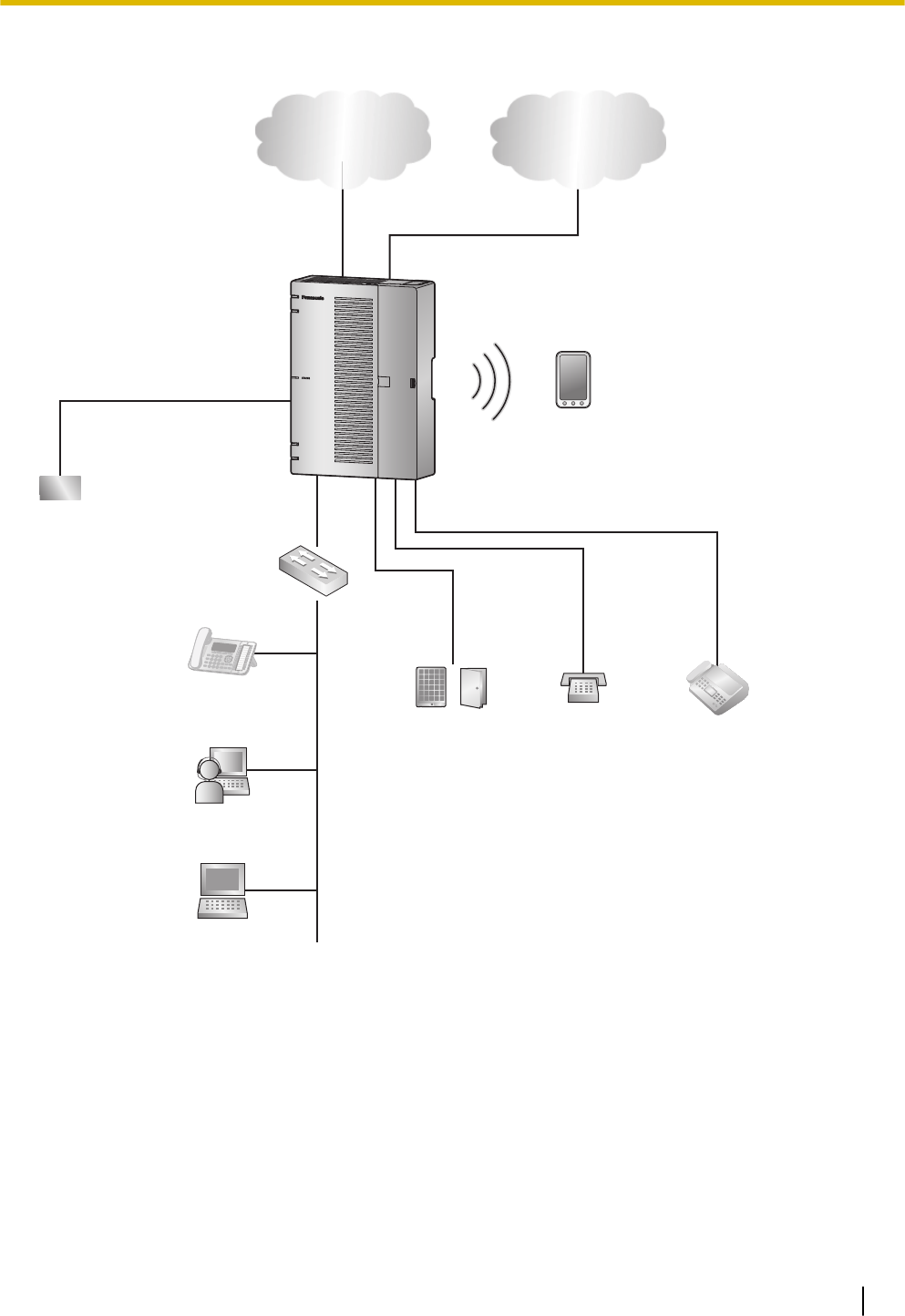
2.1.2 System Connection Diagram
WAN
PBX
Switching Hub
LAN
Doorphone &
Door Opener
SLT Fax Machine
Battery
PC
IP Network Analogue Trunk
SIP Phone*1
Smartphone
(Softphone)
IP Softphone
*1 SIP Phone: Panasonic SIP Phone is included
2.1.2 System Connection Diagram
25
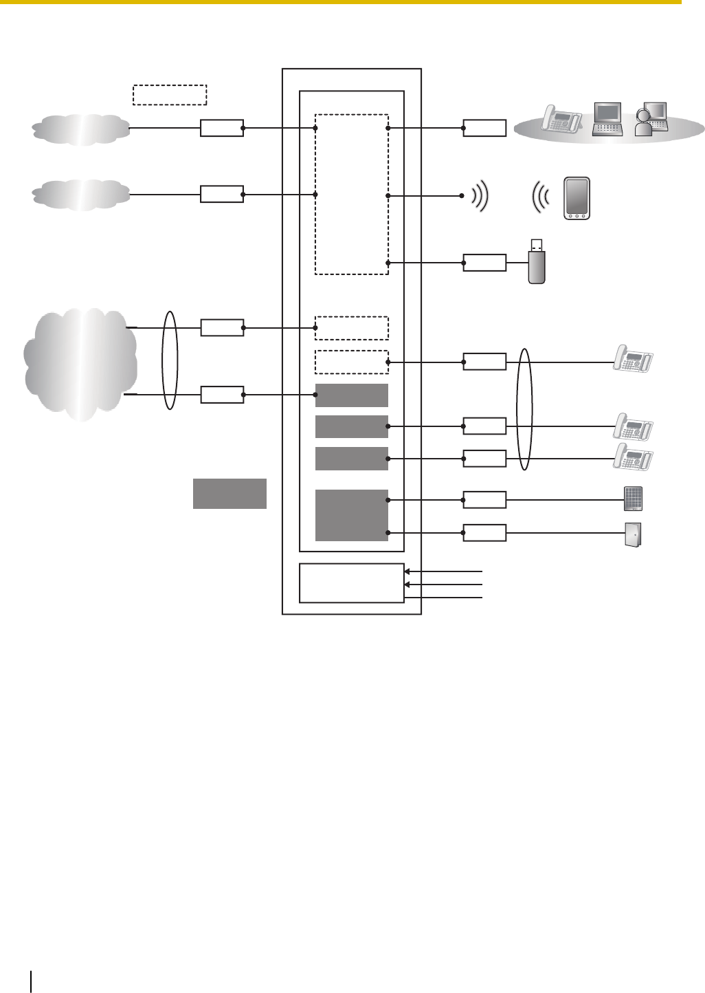
2.1.3 Block Diagram
RJ11
RJ11
RJ45
RJ45
RJ45
USB1
PSTN
8 ports
24 ports
AC Input
DC Battery input
FG
8 ports Main
PBX
LCOT4+SLC8
CPU
LCOT4
SLC8
AC/DC Unit
L2SW
Wi-Fi
DSP
RJ11
RJ11
RJ11
RJ11
SIP Trunk
Internet
LCOT4
SLC8
SLC8
DPH2
Option
card
2.1.3 Block Diagram
26
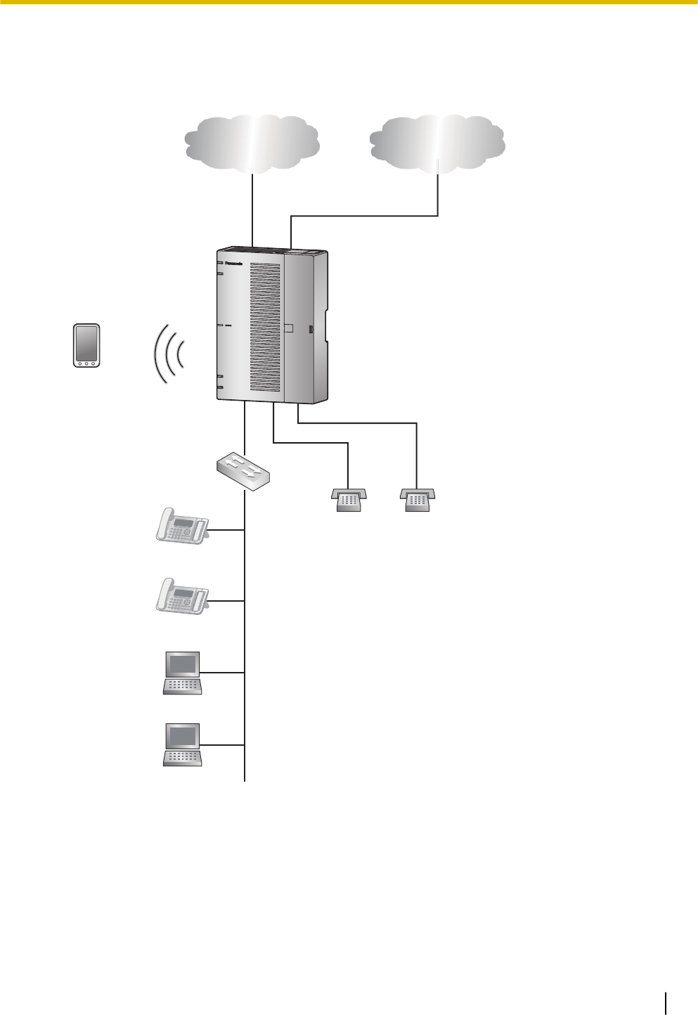
2.1.4 Typical Network Setting Example
An example of typical network connection is shown below.
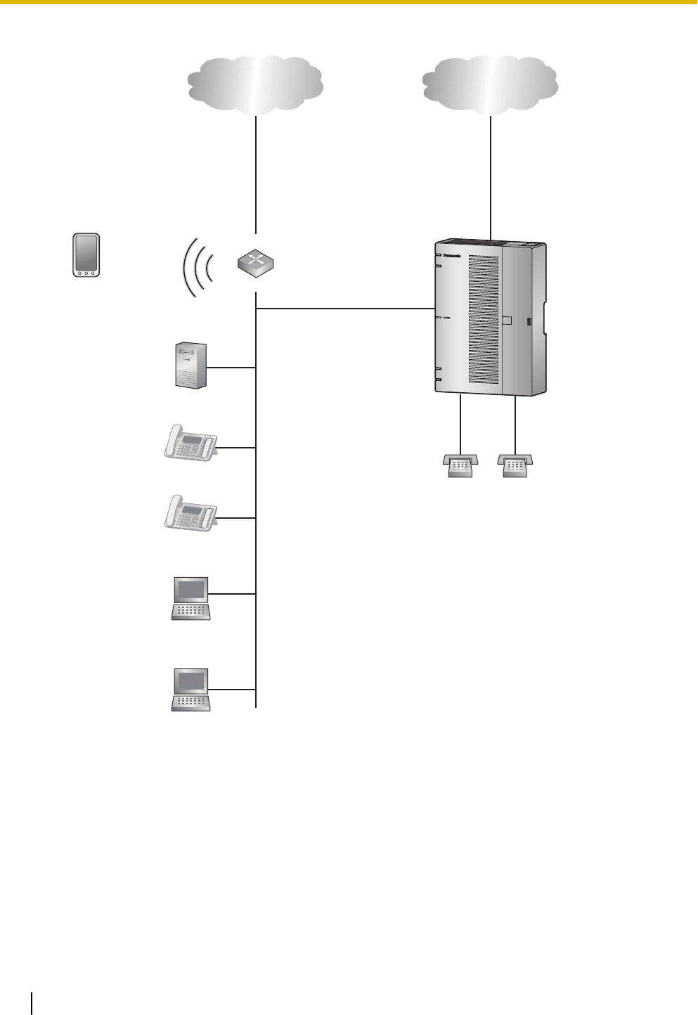
1. When installing in a new office or an office where there is no network infrastructure.
Router
PBX
IP Network Analogue Trunk
SLT SLT
Smartphone
(Softphone)
SIP Phone
LAN
WAN
SIP Phone
PC
PC
Switching Hub
Notice
•Refer to the following when the internal DHCP server will be used.
For details about DHCP server settings, refer to "Network Configuration-[4-2]LAN Settings-
◆DHCP Mode" in the Programming Item List.
2.1.4 Typical Network Setting Example
27
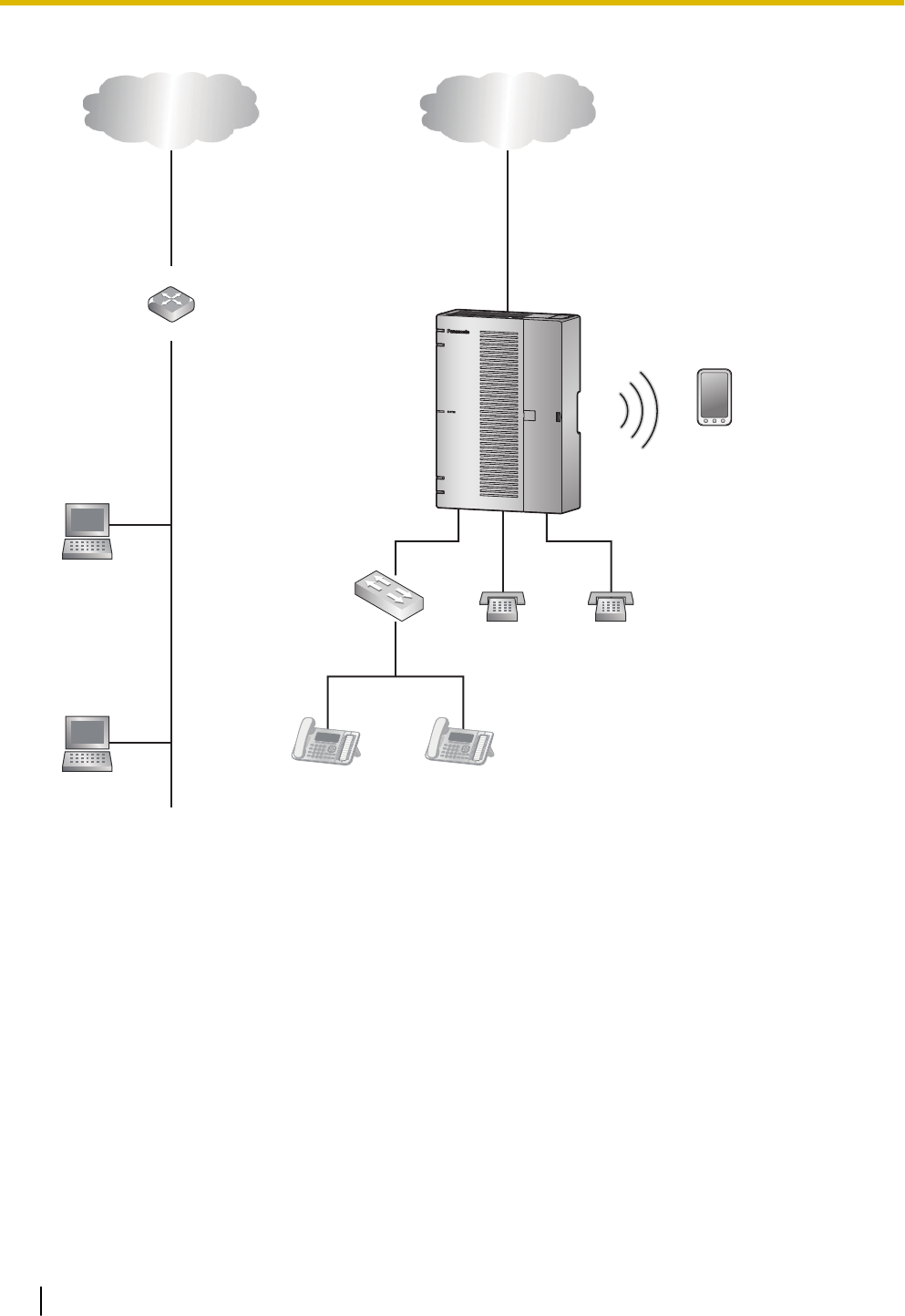
2. When installing in an office that already has a network infrastructure.
IP Network Analogue Trunk
Router
SLT SLT
PBX
Smartphone
(Softphone)
SIP Phone
SIP Phone
DHCP Server
PC
PC
WAN
LAN
Note
–Dynamic Host Configuration Protocol (DHCP) Server
Description
The PBX has a built-in DHCP server. When the DHCP server is enabled, the PBX will auto-
matically assign IP addresses to other devices on the network.
Using a DHCP server simplifies network management by removing the need to assign IP ad-
dresses to devices manually.
Notice
•If an external DHCP server is in use, the DHCP Server feature of the PBX must be disabled.
2.1.4 Typical Network Setting Example
28

For details about DHCP server settings, refer to "Network Configuration-[4-2]LAN Settings-
◆DHCP Mode" in the Programming Item List.
2.1.4 Typical Network Setting Example
29
3. When installing the PBX without connecting it to an existing network.
Switching Hub
IP Network Analogue Trunk
Router
WAN
LAN
SLT SLT
PBX
Smartphone
(Softphone)
SIP Phone SIP Phone
PC
PC
Notice
•Refer to the following when the internal DHCP server will be used.
For details about DHCP server settings, refer to "Network Configuration-[4-2]LAN Settings-
◆DHCP Mode" in the Programming Item List.
2.1.4 Typical Network Setting Example
30

2.2 Optional Equipment
2.2.1 Optional Equipment
Model No. Model Name Description
KX-HT82480 4-Port Analogue Trunk
Card
4 ports Analogue CO interface with Caller ID
(LCOT4)
KX-HT82470 8-Port Single Line
Telephone Extension
Card
8 ports Standard Telephone Line Interface with
Caller ID & Message waiting Lamp (SLC8)
KX-HT82460 2-Port Doorphone/Door
Opener Card
2 ports Panasonic Proprietary Door phone Interface
with door opener (no sensor interface) (DPH2)
2.2 Optional Equipment
31

2.3 Specifications
2.3.1 General Description
CPU MIPS 34Kc 720MHz
Power Input AC 100-240 V,50/60 Hz/60 Hz,1.3-0.9A
Power
Consumption
(when fully
mounted)
60 W
External Backup
Battery
External battery port is supported.
Memory Backup
Duration
Data retention period 7 years
Dialling Trunk Dial Pulse (DP) 10 pps, 20 pps
Tone (DTMF) Dialling with Caller ID (FSK/DTMF)
Extension Dial Pulse (DP) 10 pps, 20 pps
Tone (DTMF) Dialling with Caller ID (FSK)
Mode
Conversion
DP-DTMF, DTMF-DP
Ring Frequency 20 Hz/25 Hz (selectable)
Operating
Environment
Temperature 0 °C to 40 °C(32 °F to 104 °F)
Humidity 10 % to 90 % (non-condensing)
LAN Port WAN port 10BASE-T/100BASE-TX/1000BASE-T
WAN/LAN port
LAN port
Wireless LAN Antenna Built-in antenna
Transmission method 2 x 2 MIMO
Communication
standard
IEEE802.11n/b/g
Frequency range
(centre frequency)/
Channel
–For North America / Latin America / Taiwan:
2.412 GHz - 2.462 GHz (1 - 11ch)
–For all other countries / areas:
2.412 GHz - 2.472 GHz (1 - 13ch)
Peak transmission
power
100 mW
Security WPA/WPA2-PSK (TKIP/AES)
Open System (WEP64/WEP128)
WPS PBC method (push button method), PIN method (PIN code
method)
USB port USB 2.0 Type-A connector
Dimension 297 mm (W) x 210 mm (H) x 80 mm (D)
2.3 Specifications
32
(11-3/4 in x 8-1/4 in x 3-1/8 in)
Weight (when fully mounted) Under 2.1 kg(4.7 lb)
Installation Environment Wallmount
Horizontal (Desktop) installation
2.3.2 Characteristics
Terminal Equipment Loop Limit •SLT: 600 Ω including set
•Doorphone: 20 Ω
Minimum Leakage Resistance 15 000 Ω minimum
Maximum Number of Extension
Instruments per Line
1 for SLT
Ring Voltage 75 Vrms at 20 Hz/25 Hz depending on the Ringing Load
Trunk Loop Limit 1600 Ω maximum
Hookswitch Flash/Recall Timing
Range
24 ms to 2032 ms
2.3.3 System Capacity
Type and Maximum Number of Slots
The PBX supports the following type and number of slots.
Items Maximum Number Remarks
Total Trunk (Channel/Port) 8
SIP Trunk (Channel) 8
Analogue Trunk
(Port)
8 1 LCOT4 option card is required
Total Extension (Channel/Port) 24
SIP Extension
(Channel)
24 Include softphone for smartphone or
Parsonal Computer
Analogue Extension
(Port)
24 2 MCSLT8 option cards are required
Wireless LAN access point 1 Target throughput *1 *2
DISA/AA/VM channel 8
System Concurrent call 8
*1 Target throughput under ideal condition
IEEE802.11b: 5-6 Mbps
IEEE802.11g: 20 Mbps
IEEE802.11n: 70-80 Mbps
QoS feature (IEEE802.11eEDCA) is supported.
*2 The actual line speed may be different depending on the network environment and the wireless devices connected.
2.3.2 Characteristics
33
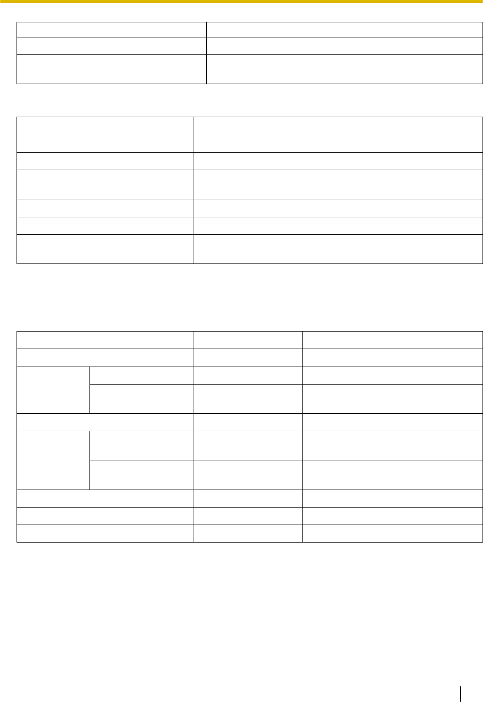
Main Unit
Right Side View (The cable cover is open.)
A A B
Inside View (The front cover is open.)
DC
A Dummy cover plates for Extension Card Slots
B Dummy cover plates for Trunk/Doorphone Card Slots
C Extension Card Slot
D Trunk/Doorphone Card Slot
Maximum Optional Service Cards
The following number of card can be installed in the Physical Slots or Virtual Slots of the PBX.
Note
•Any card that exceeds the capacity of the PBX will be ignored.
•When the PBX starts up with an invalid configuration, some cards will be ignored.
Slot
Slot type Card Name Maximum Number
Pre-installed LCOT4 1
SLC8 1
2.3.3 System Capacity
34

Slot type Card Name Maximum Number
Trunk/Doorphone Slot LCOT4 1
DPH2 1
Extension Slot SLC8 2
DSP Resources
The KX-HTS series has a built-in DSP with a maximum of 14 DSP resources.
This DSP is used for switching the TDM and IP terminals.
1. The definition of TDM and IP
Subject Remarks
TDM Trunk Analogue Trunk
TDM Extension Analogue Telephone ( SLT, Fax, etc.)
Doorphone
SIP Trunk SIP Trunk
IP Extension SIP phone
Softphone on a smartphone or personal computer
Others DISA / Automated Attendant / Voicemail /
Conference
2. Resource count
DSP resources are counted as follows.
The codec typically used for SIP Trunks is G.711. Some countries such as South Africa use G.729.
In this chart, IP extensions are using G.711.
Case Connection DSP Resource count
(SIP trunk : G711)
DSP Resource Count
(SIP trunk : G729)
1 TDM Trunk <-> TDM Trunk 0 (TSW) 0 (TSW)
2 TDM Trunk <-> TDM Extension 0 (TSW) 0 (TSW)
3 TDM Trunk <-> IP Extension 1 (DSP) 1 (DSP)
4 TDM Trunk <-> Others 1 (DSP) 1 (DSP)
5 SIP Trunk <-> SIP Trunk *1) 0 (P2P) / 2(DSP) *1) 0 (P2P) / 2(DSP)
6 SIP Trunk <-> TDM Extension 1 (DSP) 1 (DSP)
7 SIP Trunk <-> IP Extension 0 (P2P) 2 (DSP)
8 SIP Trunk <-> Others 1 (DSP) 1 (DSP)
9 TDM Extension <-> TDM
Extension
0 (TSW) 0 (TSW)
10 TDM Extension <-> Others 1 (DSP) 1 (DSP)
11 IP Extension <-> IP Extension *1) 0 (P2P) / 2(DSP) *1) 0 (P2P) / 2(DSP)
12 IP Extension <-> Others 1 (DSP) 1 (DSP)
*1 P2P or DSP is selectable for the connection's base setting.
Note
The recommended codec for SIP trunk service is G.711.
2.3.3 System Capacity
35

2.3.3 System Capacity
36

Section 3
Installation
This section describes the procedures to install the
PBX. Detailed instructions for planning the installation
site, installing the main unit and optional service cards,
and cabling of peripheral equipment are provided. Fur-
ther information on peripheral equipment installation is
included.
37

3.1 Before Installation
3.1.1 Before Installation
Please read the following notes concerning installation and connection before installing the PBX and termi-
nal equipment.
Be sure to comply with all applicable laws, regulations, and guidelines.
Notice
Panasonic assumes no responsibility for injuries or property damage resulting from failures arising out of
improper installation or operation inconsistent with this documentation.
Safety Installation Instructions
WARNING
When installing telephone wiring, basic safety precautions should always be followed to reduce the risk
of fire, electric shock and injury to persons, including the following:
•Never install telephone wiring during a lightning storm.
•Never install telephone jacks in wet locations unless the jack is specifically designed for wet loca-
tions.
•Never touch uninsulated telephone wires or terminals unless the telephone line has been disconnec-
ted at the network interface.
•Use caution when installing or modifying telephone lines.
•Anti-static precautions should be taken during installation.
Installation Precautions
The PBX can be mounted on a wall or placed on a desktop, and should be installed in an accessible loca-
tion where it can be easily inspected and maintained.
To prevent malfunction, noise, or discolouration, follow the instructions below:
WARNING
Do not install the system in the following locations:
•Areas where shocks or vibrations are frequent or strong. Such activity may lead to the product falling
over and causing injury, or may impair the product’s performance.
•Areas with high amounts of dust. High amounts of dust can lead to fire or electric shock, and impair
the performance of the product.
CAUTION
Do not install the system in the following locations:
•In direct sunlight and hot, cold, or humid places. (Temperature range: 0 °C to 40 °C [32 °F to
104 °F])
•Areas where sulphuric gases may be present, such as near thermal springs.
•Near devices that generate high frequencies, such as sewing machines or electric welders.
•Locations where other objects will obstruct the area around the PBX. Be especially careful to leave
at least 5 cm (2 in) to the sides of the PBX for ventilation.
•Locations where condensation can occur.
Notice
Do not install the system in the following locations:
3.1 Before Installation
38

•On or near computers, or other office equipment, as well as microwave ovens or air conditioners. (It
is preferable not to install the system in the same room as the above equipment.)
•Within 1.8 m (6 ft) of radios and televisions. (Both the PBX and PTs should be at least 1.8 m [6 ft]
away from such devices.)
Do not perform the following:
•Do not block the openings of the PBX.
•Do not stack up the optional service cards.
Wiring Precautions
Be sure to follow these instructions when wiring the unit:
CAUTION
•Avoid using the same AC outlet for computers and other office equipment, as noise generated by
such equipment may hamper system performance or interrupt the system.
•Unplug the system from its power source when wiring, and plug the system back in only after all wir-
ing is completed.
•Trunks should be installed with surge protectors. For details, refer to "3.2.9 Surge Protector Installa-
tion".
Notice
•Use 1-pair telephone cables when connecting SLTs, data terminals, answering machines, comput-
ers, etc.
•Mis-wiring may cause the PBX to operate improperly. Refer to "Installation" when wiring the system.
•If an extension does not operate properly, disconnect the telephone from the extension line and con-
nect it again, or turn off the PBX using the power switch, then turn it on again.
•Use twisted pair cable for trunk connection.
•To prevent signal noise from interfering with the performance of the product, do not run unshielded
telephone cables near AC power cables, computer cables, AC power sources, etc. When running
cables near other noise-generating devices or cables, use shielded telephone cables or shield the
telephone cables with metal tubing.
Preparing the Network Environment
Be sure to prepare your network’s environment for the installation of the PBX according to the intended PBX
networking configuration.
3.1.1 Before Installation
39
3.2 Installation of the PBX
3.2.1 Unpacking
Unpack the box and check the items below:
•Main unit
•AC power cord
•Strap band
•Screw × 2 (For Wall Mounting)
•Washer × 2 (For Wall Mounting)
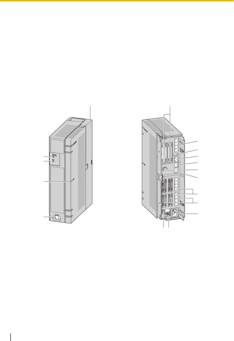
3.2.2 Names and Locations
A
B
C
D
E F
M
L
G
H
I
J
K
S
O
N P
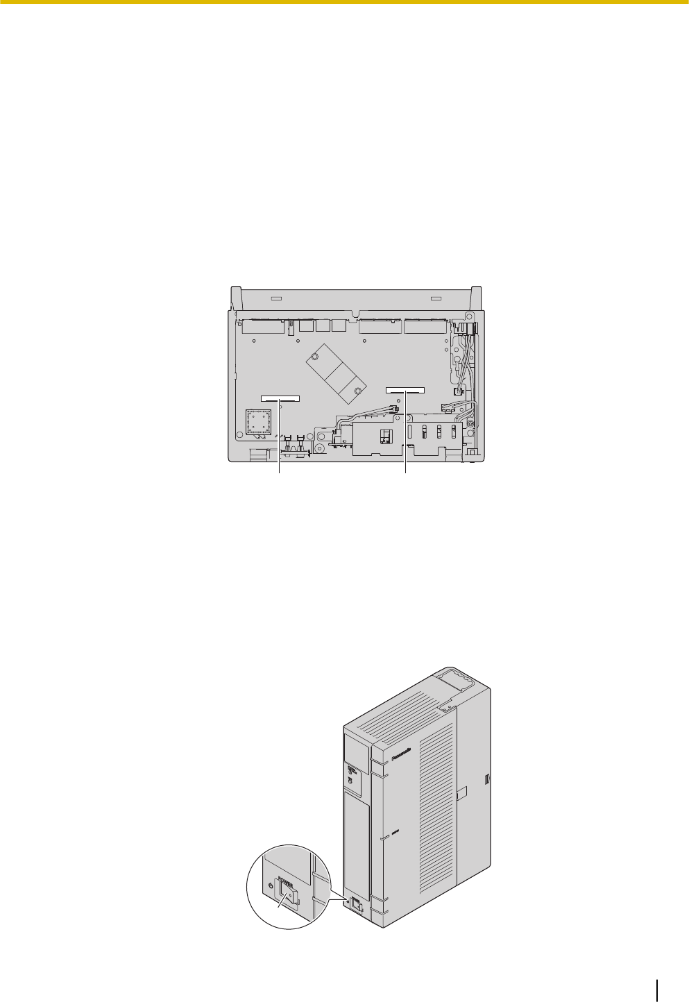
A STATUS Indicator
B Initialize Switch
C WPS Switch
D Power Switch
E Cable Cover
F Trunk/Doorphone Free Slot
G CO4 Interface
H USB Port
I WAN1 port
J LAN2 / WAN2 port
3.2 Installation of the PBX
40
K LAN1 port
L Extension slot
M SLT8 Interface
N FG Terminal
O AC Inlet
P External Battery
Q Extension Card Slot
R Trunk/Doorphone Card Slot
S Hook Clip
Inside View (The front cover is open.)
RQ
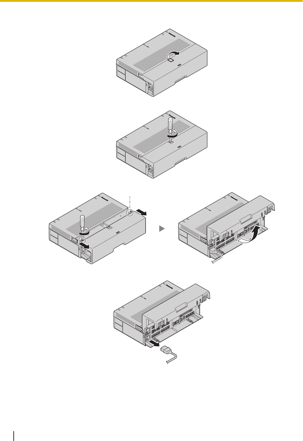
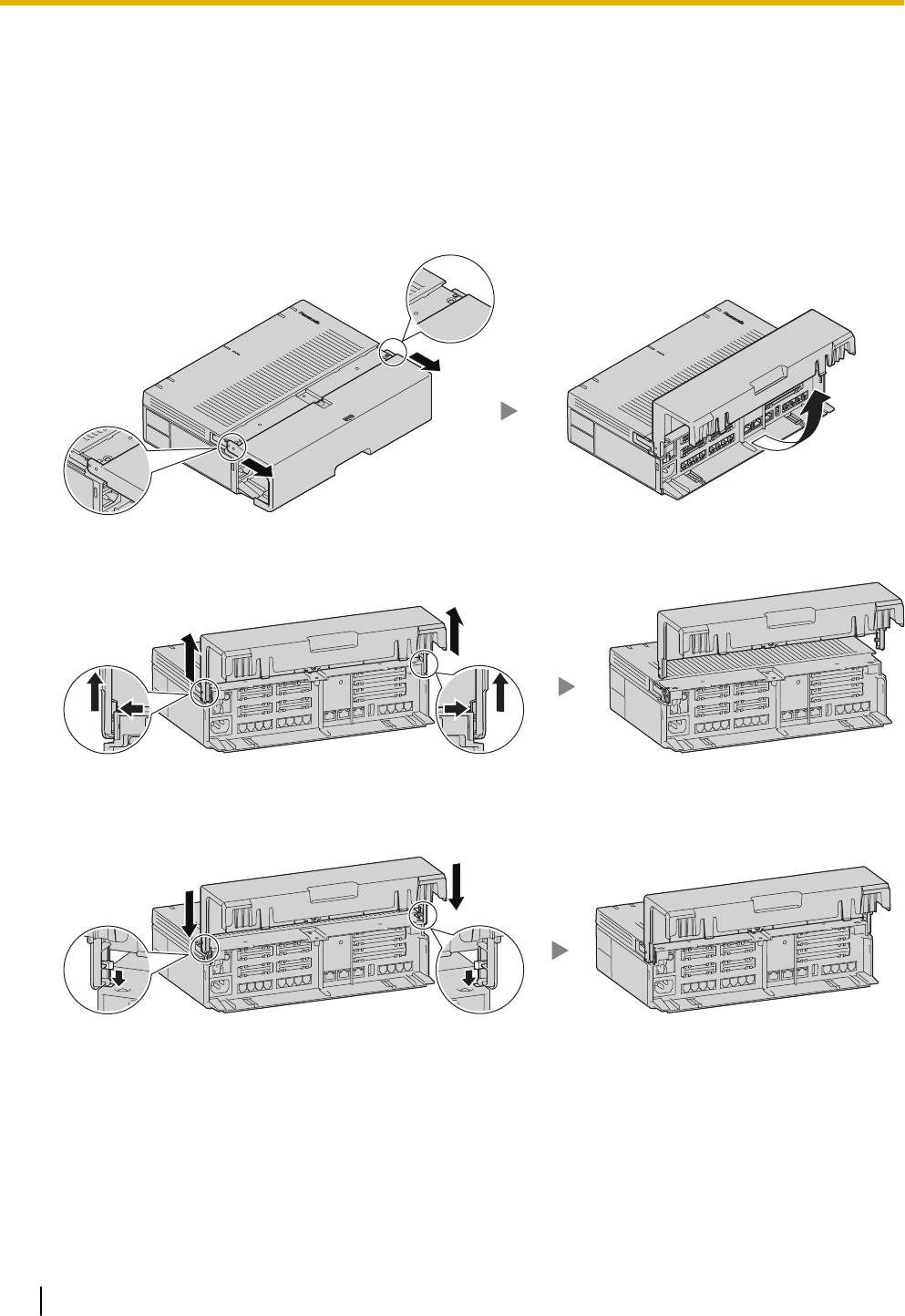
3.2.3 Opening/Closing the front cover
Opening the front cover
CAUTION
Before opening the front cover, the AC power cord must be removed from the AC inlet.
Do not open the front cover soon after turning off the power. There is a risk of receiving burns.
1. Confirm that the power switch is turned off.
A
3.2.3 Opening/Closing the front cover
41
A Power Switch
2. Turn the screws anticlockwise to loosen them.
3. Slide out the cable cover and turn the screws anticlockwise to loosen them.
4. Disconnect the power cable.
Note
In order to turn off the PBX’s power, a system shutdown using Web Maintenance Console must first
be performed. For details, refer to "5.4 System Control—System Shutdown" in the Programming
Item List.
3.2.3 Opening/Closing the front cover
42
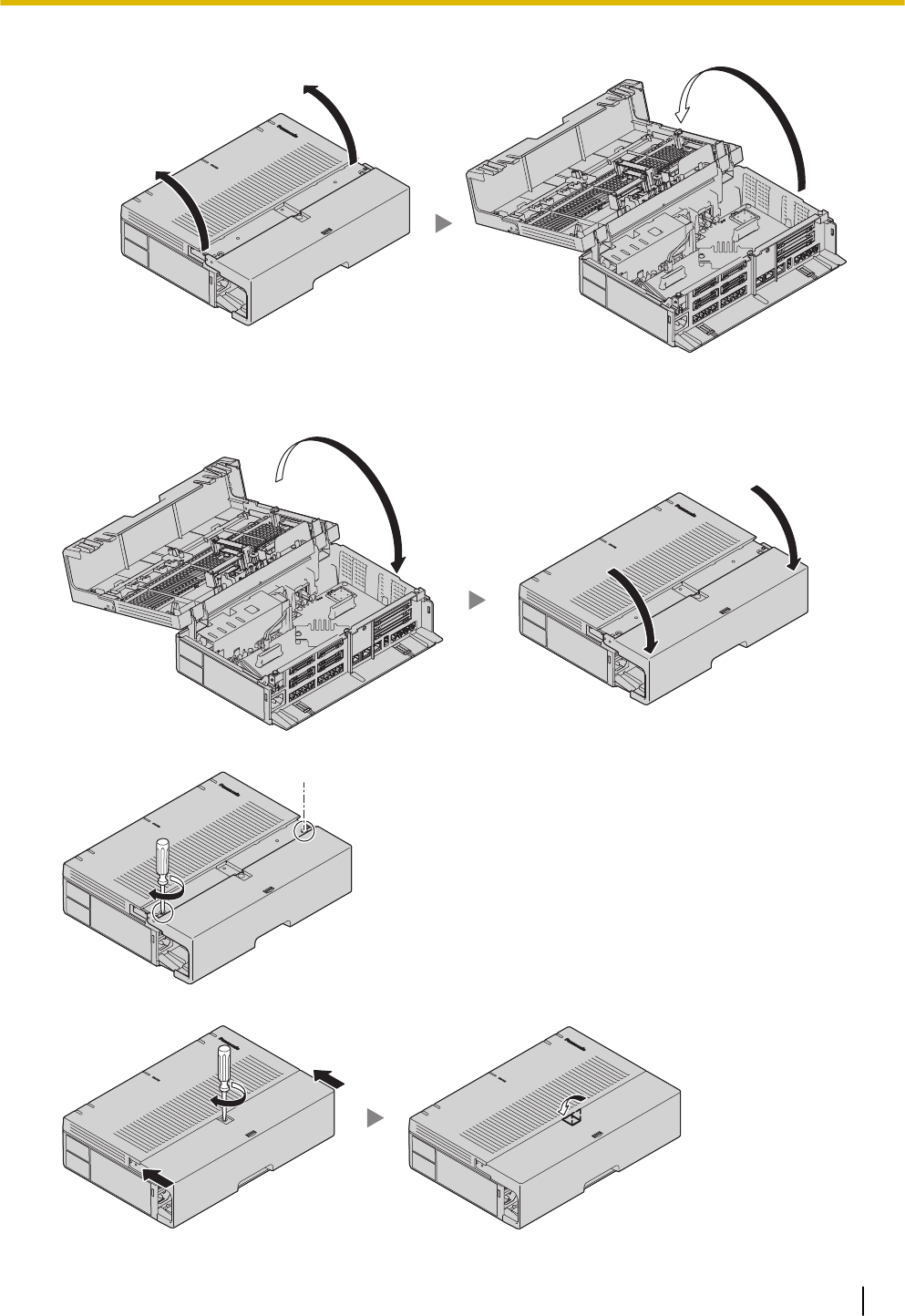
5. Open the front cover.
Closing the front cover
1. Close the front cover.
2. Turn the screws clockwise to tighten them.
3. Slide in the cable cover and turn the screws clockwise to tighten them.
3.2.3 Opening/Closing the front cover
43
CAUTION
For safety reasons, fix the front cover and cable cover of the PBX with screws.
3.2.3.1 Removing/Attaching the Cable Cover
If you prefer, you can remove the cable cover.
Removing the Cable Cover
1. Slide out the cable cover and open it.
2. Holding the cable cover open at about a 90 angle, remove the front cover by pushing it in the direction of
the arrow as shown below.
Attaching the Cable Cover
1. Fit the cable cover to the main unit as shown below, and then close the cable cover.
CAUTION
For safety reasons, fix the front cover and cable cover of the PBX with screws.
3.2.4 Frame Earth Connection
1. Loosen the screw.
2. Insert an earthing wire (user-supplied).
3. Tighten the screw.
3.2.4 Frame Earth Connection
44
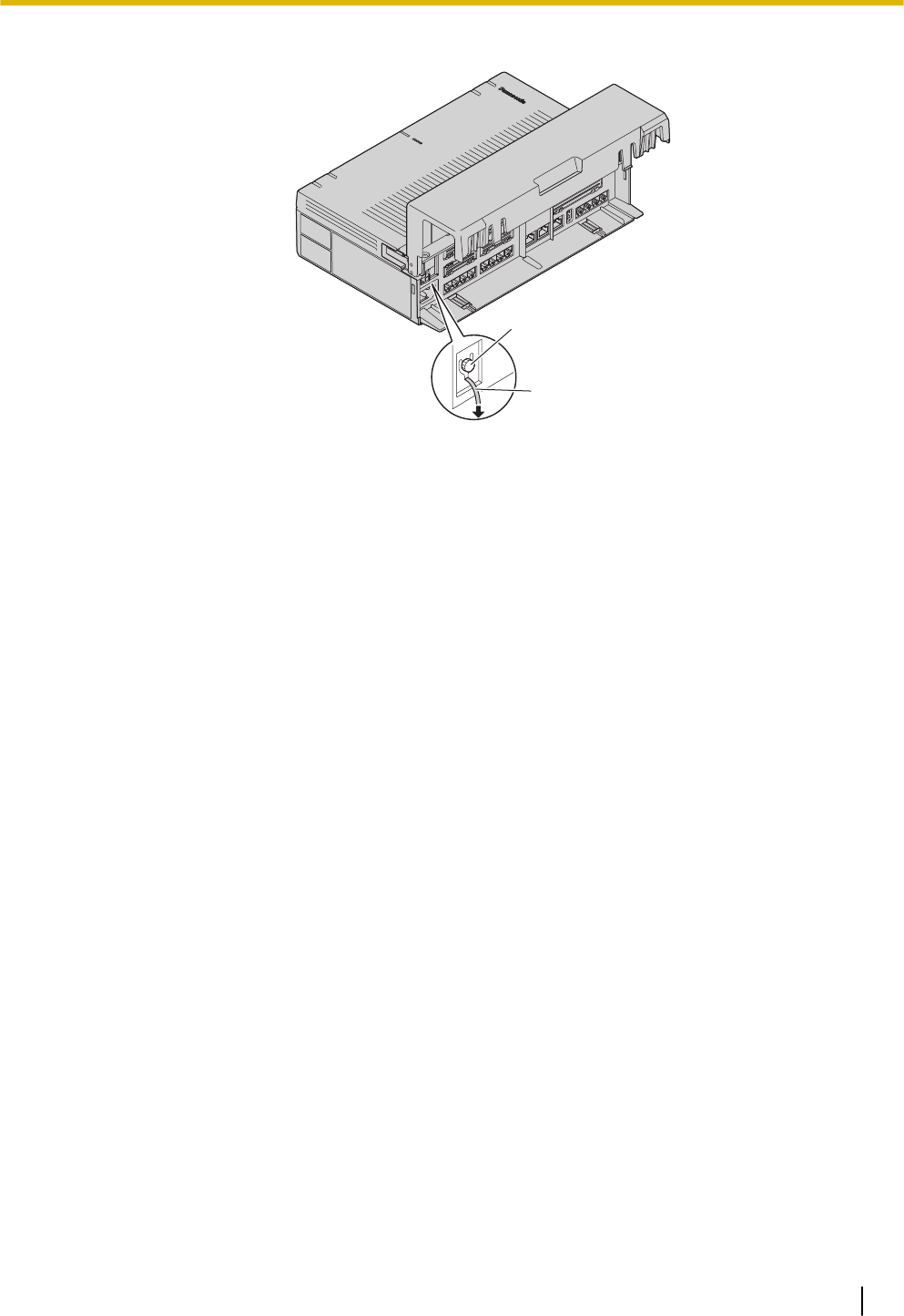
4. Connect the earthing wire to earth.
A
B
(1)
(1) To earth
A Screw
B Earthing wire
WARNING
•Proper earthing (connection to earth) is very important to reduce the risk to the user of electrocu-
tion or to protect the PBX from the bad effects of external noise in the case of a lightning strike.
•The earthing wire of the AC cable has an effect against external noise and lightning strikes, but it
may not be enough to protect the PBX and to ensure electromagnetic compatibility. A permanent
connection between earth and the earth terminal of the PBX must be made.
CAUTION
For earthing wire, green-and-yellow insulation is required, and the cross-sectional area of the con-
ductor must be more than 0.75 mm2 or 18 AWG.
Note
Be sure to comply with applicable local regulations (e.g., laws, guidelines).
3.2.5 Installing/Removing the Optional Service Cards
CAUTION
•Before touching the product (PBX, cards, etc.), discharge static electricity by touching ground or
wearing an earthing strap. Failure to do so may cause the PBX to malfunction due to static electrici-
ty.
•When installing or removing the optional service cards, the power switch must be turned off, and the
AC power cord must be removed from the AC inlet.
•When installing or removing the optional service cards, do not put pressure on any parts of the
mother board. Doing so may result in damage to the PBX.
•Disconnect the AC power source before servicing the equipment.
Notice
Make sure the AC power cord is not connected to the AC inlet of the PBX.
3.2.5 Installing/Removing the Optional Service Cards
45
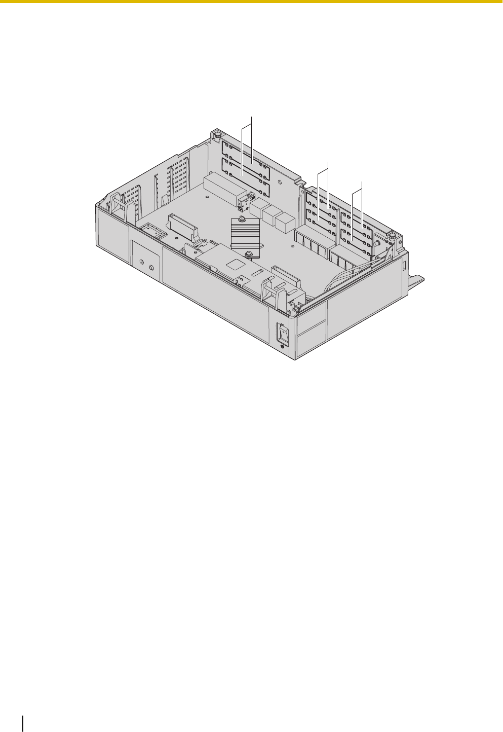
Installing an Optional Service Card in the Free Slots
In the Main Unit, there are free slots for trunk/doorphone cards and free slots for extension cards.
In the free slots for trunk/doorphone cards, you can install one each of the following cards: LCOT4, DPH2.
In the free slots for extension cards, you can install one or more of the following card: SLC8.
For details, refer to the description of each optional service card in "3.3.2 LCOT4 Card (KX-HT82480)",
"3.3.3 SLC8 Card (KX-HT82470)" and "3.3.4 DPH2 Card (KX-HT82460)".
A
B
B
A Trunk/Doorphone Card Slots
B Extension Card Slots
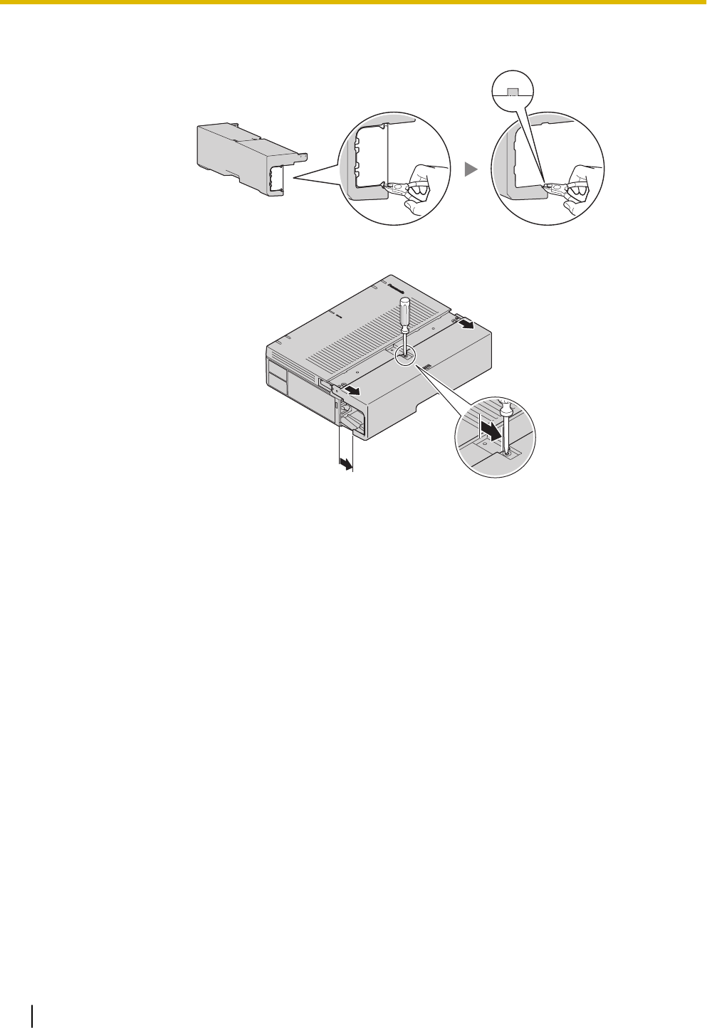
1. Remove the dummy cover plate for the Free slot.
Cut off any excess plastic in order to make the surface smooth.
3.2.5 Installing/Removing the Optional Service Cards
46
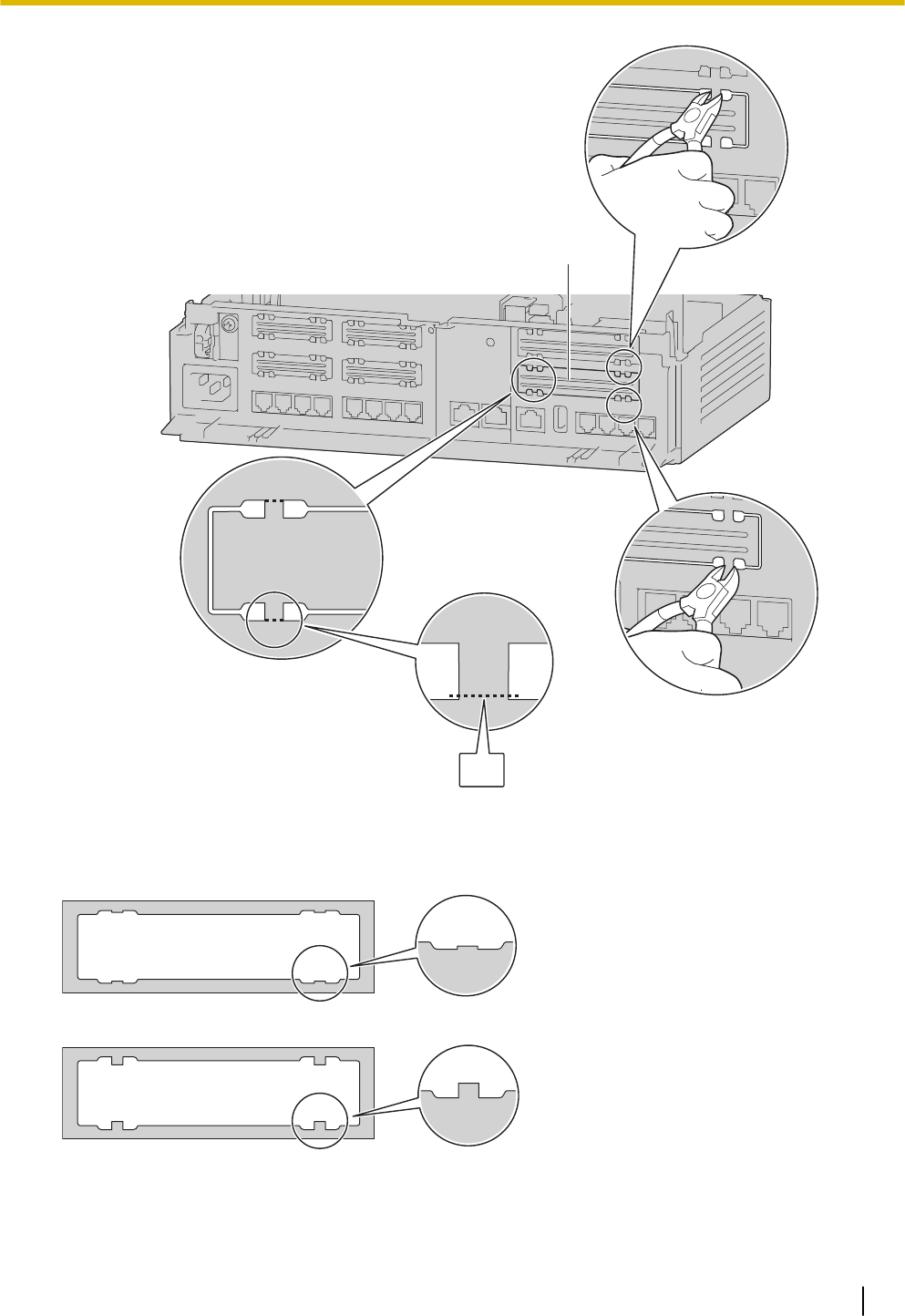
A
(1)
A Dummy Cover Plate
(1) Cut here.
Correct
Incorrect
Note
When removing the dummy cover plate, use plastic nippers. We do not recommend using a knife
such as a retractable utility knife.
3.2.5 Installing/Removing the Optional Service Cards
47
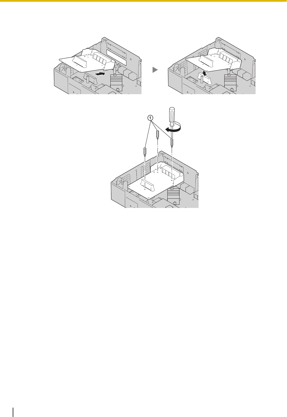
2. Position the card in the open slot, making sure that the tabs on the both sides of the card fit into place.
Then, holding the card firmly in place, lower the rear end so that the holes of the card are aligned with
the screw holes.
3. Insert the spacers (①) into the holes on the card, and tighten the spacers to secure the card.
Note
When using an LCOT4 card with a DPH2 card, install the LCOT4 card in the bottom.
4. Connect cables to appropriate ports of the card. For details about pin assignments, refer to the appropri-
ate section in "3.5 Connecting Extensions" and "3.6 Connecting Doorphones and Door Openers".
Note
Make sure to connect cables after installing the card in the PBX, not before.
3.2.5 Installing/Removing the Optional Service Cards
48
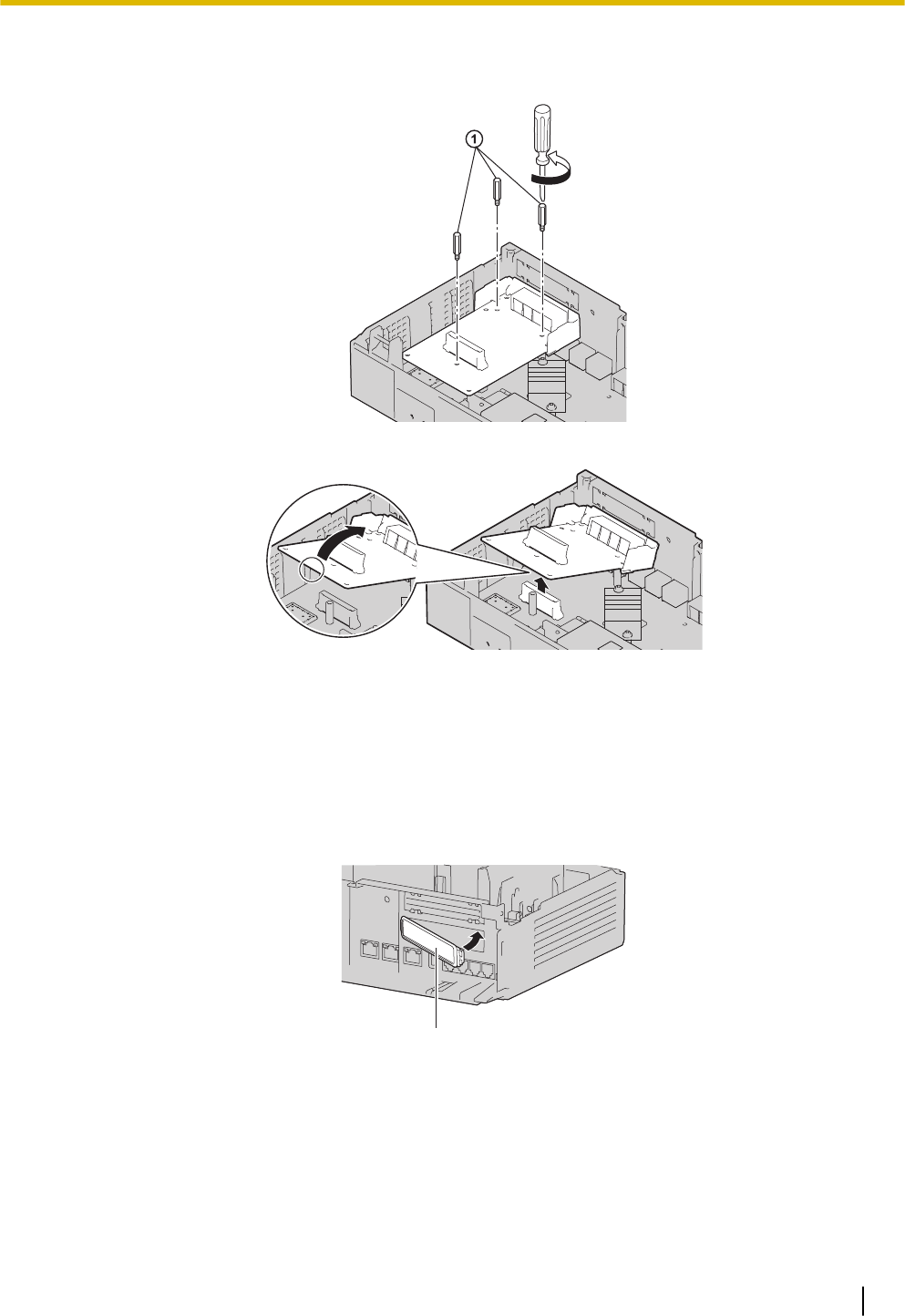
Removing Optional Service Card from the Free Slot
1. Loosen and remove the spacers (①).
2. Holding the rear end of the card, pull the card in the direction of the arrows.
3.2.5.1 Slot covers
Only remove the dummy cover plates when you are planning to install an optional service card. If you do not
install an optional service card, insert a slot cover included with the option service card, as shown in the
following procedure.
To insert a slot cover
1. With the clip-side of the slot cover on the left, insert the right edge of the cover in the slot.
A
A Slot cover
3.2.5 Installing/Removing the Optional Service Cards
49
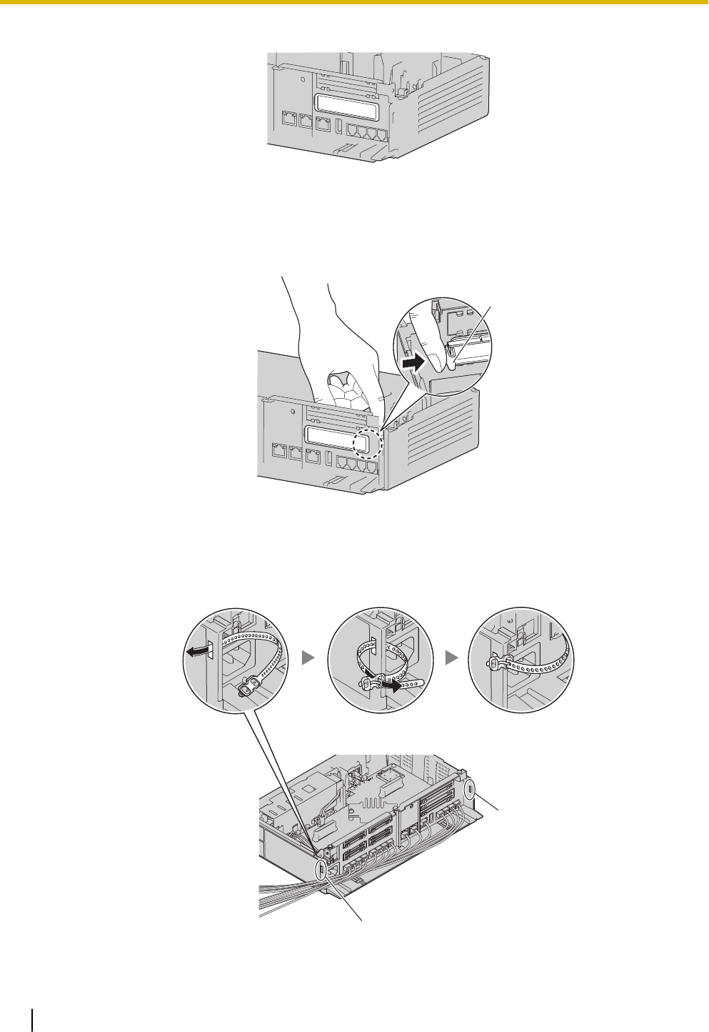
2. Push the left edge in until it clicks securely into place.
To remove a slot cover
1. Remove the front cover.
Refer to "Opening the front cover" in "3.2.3 Opening/Closing the front cover".
2. From the inside, push the tab of the slot cover to the right and push out the left edge of the slot cover.
A
A Tab
3.2.6 Securing the Cables
1. Pass the included strap through either of the 2 slits for securing cables according to your needs.
A
A
A Slit
3.2.6 Securing the Cables
50
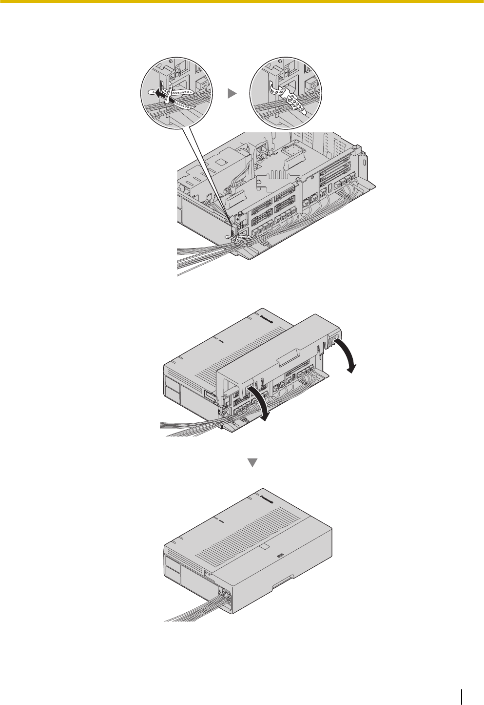
•If you prefer, you can cut the other side of the cable cover and run the cables through that open-
ing. For safety reasons, smooth the cut edges.
•When there are too many cables to fully slide in the the cable cover, leave the cable cover slid
open, and tighten the screws with the cable cover in that position.
CAUTION
For safety reasons, fix the front cover and cable cover of the PBX with screws.
3.2.7 Placing the PBX on a Desktop
When placing the PBX on a desktop, make sure to follow these instructions.
WARNING
Be careful not to drop any components. Dropping components may damage them or cause an injury.
CAUTION
•When the PBX is placed on a desktop, make sure that the PBX is placed as indicated in the diagram
below. Do not place it on its side or upside down.
•Do not block the openings of the PBX. Allow space of at least 20 cm (8 in) above and 10 cm (4 in) at
the sides of the PBX.
3.2.7 Placing the PBX on a Desktop
52

Desk or Table
3.2.8 Wall Mounting
When wall mounting the main unit, use the included screws.
WARNING
•Make sure that the wall that the unit will be attached to is strong enough to support approximately 5
times the weight of the unit. If not, it is necessary for the wall to be reinforced.
•Only use the wall-mounting equipment (screws and washers) included with the PBX.
•Be careful not to drop any components. Dropping components may damage them or cause an injury.
•Proper earthing (connection to earth) is very important to reduce the risk to the user of electrocution
or to protect the PBX from the bad effects of external noise in the case of a lightning strike. (See
"3.2.4 Frame Earth Connection".)
CAUTION
•Make sure to install all necessary optional service cards in the PBX before performing the wall
mounting procedure. If it is necessary to install or remove a card, make sure to detach the PBX from
the wall before installing or removing the card.
•Do not block the openings of the PBX. Allow space of at least 20 cm (8 in) above, 10 cm (4 in) at the
sides, and 10 cm (4 in) below the PBX.
•Make sure that the surface behind the PBX is flat and free of obstacles, so that the openings on the
back of the PBX will not be blocked.
•If the PBX is not installed properly using the securing correct methods, the PBX may fall causing
serious damage.
•When driving the screws into the wall, be careful to avoid touching any metal laths, wire laths or
plates in the wall.
•When this product is no longer in use, make sure to detach it from the wall.
Note
For details about dimensions and weight of the PBX, see "2.3.1 General Description".
Wall Mounting Procedures
CAUTION
Drive mounting screws into the wall. Be careful to avoid touching any metals laths, wire laths or metal
plates in the wall.
Mounting on a Wooden Wall
The included screws may be used when mounting the main unit on a wooden wall.
3.2.8 Wall Mounting
53
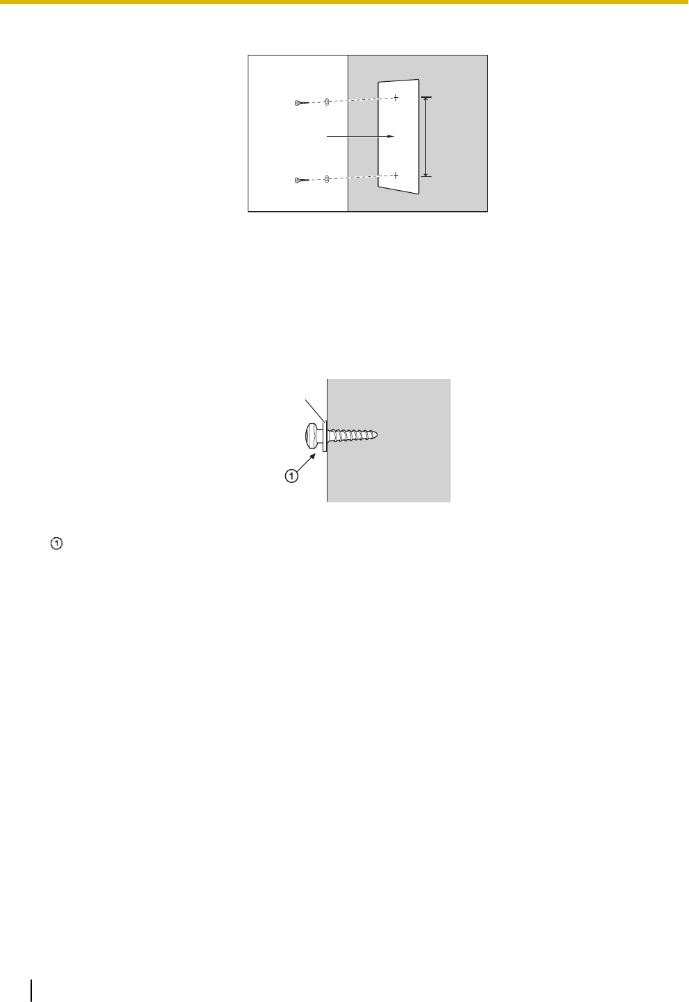
1. Place the template (found on the last page of this manual) on the wall to mark the 2 screw positions.
AB
A Template
B 225 mm (8-7 / 8 in)
Note
When you print out the template, the distance on the paper output may deviate slightly from the indi-
cated measurement. In this case, use the indicated measurement.
2. Install the screws and washers (included) to the wall.
C
C Washer
Drive the screw to this point.
Note
•As indicated above, do not tighten the screw fully.
•The pull-out strength of the installation area must be at least 294 N (30 kgf) per screw.
•Do not block the operations of the cabinet. Allow space of at least 20 cm (8 in) above and 10 cm
(4 in) at the sides of the cabinet.
•Make sure that screw heads are the same distance from the wall.
•Install the screw perpendicular to the wall.
•Be careful not to drop the cabinet.
3.2.8 Wall Mounting
54
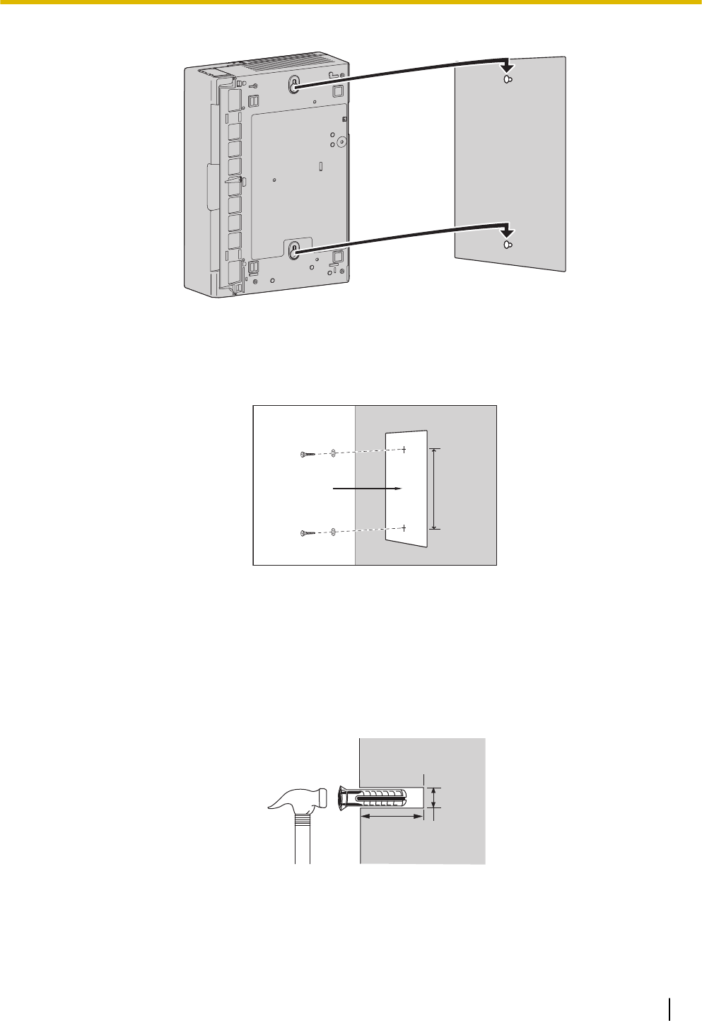
3. Hook the main unit on the screw heads.
Mounting on a Concrete
The included screws may be used when mounting the main unit on a concrete or mortar wall. User supplied
anchor plugs are also necessary.
1. Place the template (found on the last page of this manual) on the wall to mark the 2 screw positions.
AB
A Template
B 225 mm (8-7 / 8 in)
Note
When you print out the template, the distance on the paper output may deviate slightly from the indi-
cated measurement. In this case, use the indicated measurement.
2. Drill holes in the wall as marked and fit the anchor plugs (not included) into the holes.
CD
E
F
C Hammer
D Anchor Plug
E 6.4 mm (1/4 in)
3.2.8 Wall Mounting
55
F 29 mm (1-9 / 64 in)
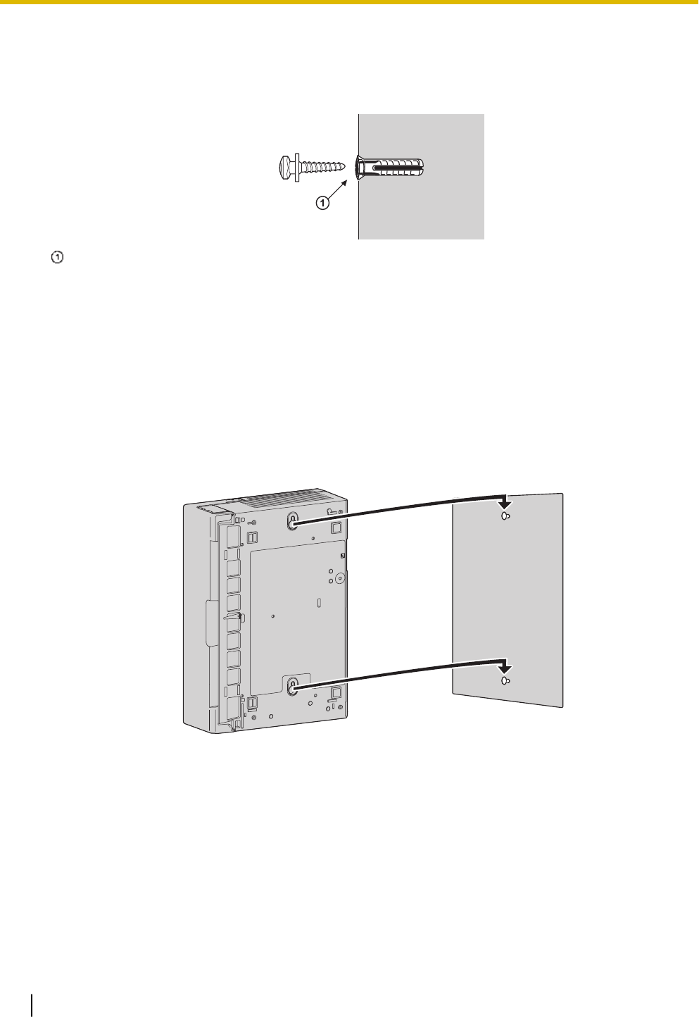
3. Fit the washers on the screws, and drive the screws into the anchor plugs.
Drive the screw to this point.
Note
•As indicated above, do not tighten the screw fully.
•The pull-out strength of the installation area must be at least 294 N (30 kgf) per screw.
•Do not block the operations of the cabinet. Allow space of at least 20 cm (8 in) above, 10 cm (4
in) at the sides, and 10 cm (4 in) below the PBX.
•Make sure that screw heads are the same distance from the wall.
•Install the screw perpendicular to the wall.
•Be careful not to drop the cabinet.
4. Hook the main unit on the screw heads.
3.2.9 Surge Protector Installation
CAUTION
Performing surge protection is essential. Make sure to follow the instructions in this section.
Overview
A massive electrical surge can be caused if lightning strikes a telephone cable 10 m (33 ft) above ground, or
if a telephone line comes into contact with a power line. A surge protector is a device that is connected to a
trunk to prevent potentially dangerous electrical surges from entering the building via the trunk and damag-
ing the PBX and connected equipment.
3.2.9 Surge Protector Installation
56
To protect the system from electrical surges, we strongly recommend connecting the system to a surge pro-
tector that meets the following specifications:
–Surge arrestor type: 3-electrode arrestor
–DC spark-over voltage: 230 V
–Maximum peak current: at least 10 kA
Additionally, proper earthing is very important for the protection of the system (refer to "3.2.4 Frame Earth
Connection").
Many countries/areas have regulations requiring surge protection. Be sure to comply with all applicable
laws, regulations, and guidelines.
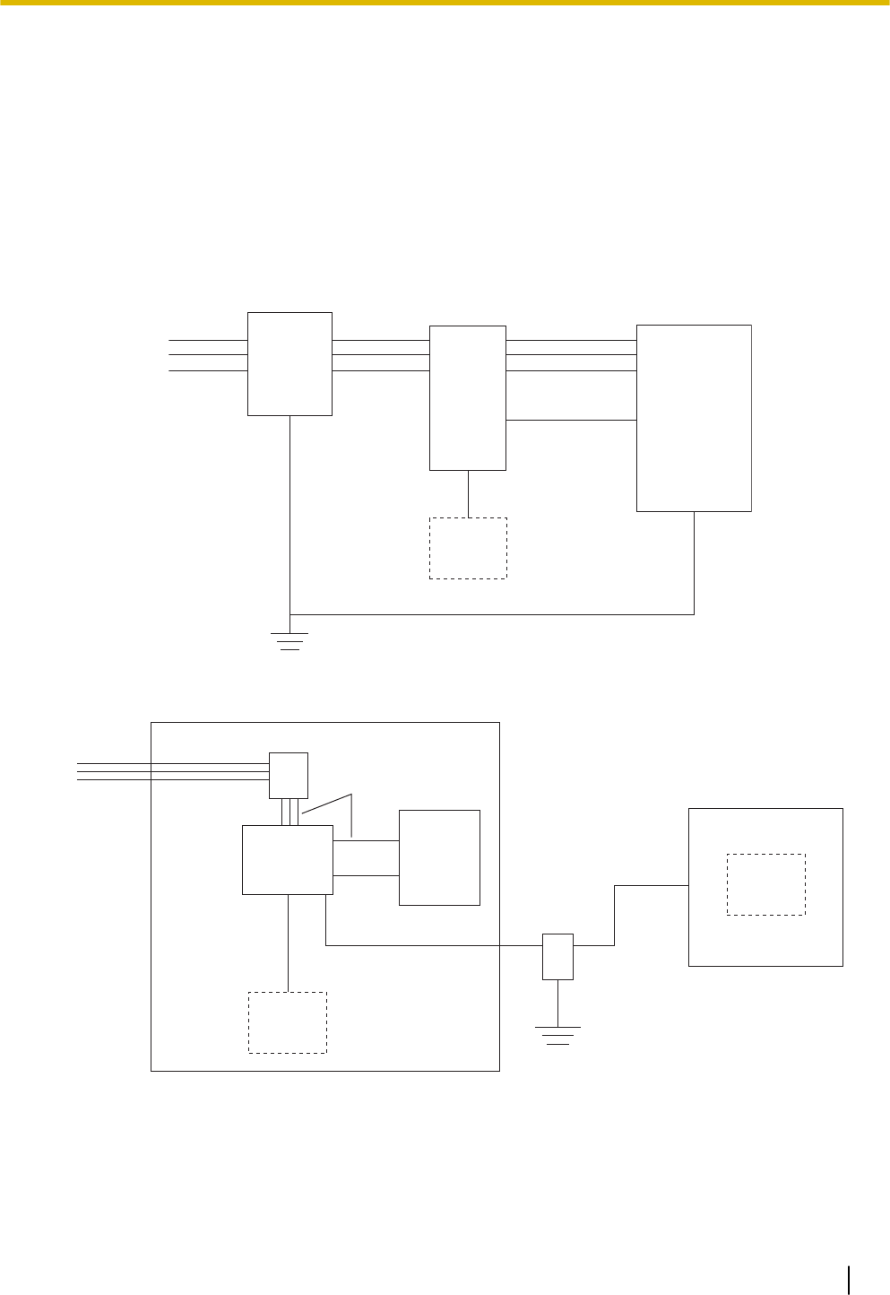
Installation
Trunk Trunk
Earth
Surge
Protector
Trunk
Extn.
Extn.
Extn.: Extension line
PBX
SLT Frame
Earth
Terminal
Board
Outside Installation
Extn.
Trunk Surge Protector
Trunk
Terminal
Board
Surge
Protector
PBX
(Main Building)
Extn. Extn.
Earth
Extn.
SLT
(Another Building)
SLT
Extn.: Extension Line
If you install an extension outside of the building, the following precautions are recommended:
a. Install the extension wire underground.
b. Use a conduit to protect the wire.
3.2.9 Surge Protector Installation
57

Note
The surge protector for an extension is different from that for trunks.
Installation of an Earth Rod
Trunk
PBX
Earth Rod
(Underground)
Surge Protector
Earthing
Wire
1. Connect the earth rod to the surge protector using an earthing wire with a cross-sectional area of at
least 1.3 mm2.
2. Bury the earth rod near the protector. The earthing wire should be as short as possible.
3. The earthing wire should run straight to the earth rod. Do not run the wire around other objects.
4. Bury the earth rod at least 50 cm (20 in) underground.
Note
•The above figures are recommendations only.
•The length of earth rod and the required depth depend on the composition of the soil.
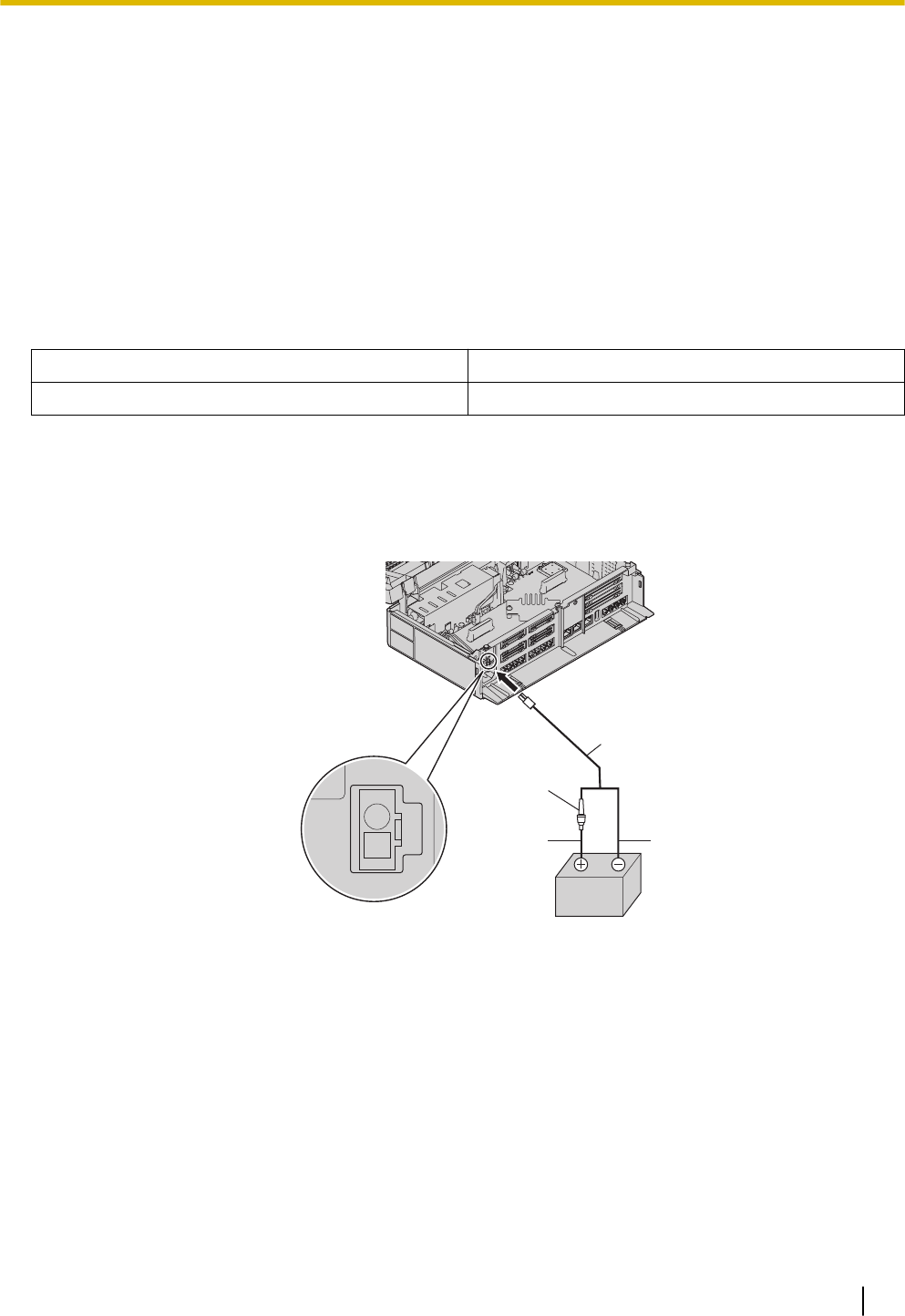
3.2.10 Backup Battery Connection
The backup battery and Back-up Battery Cable provide a backup power supply to allow full use of the PBX
in the event of a power failure. In case of power failure, the backup battery automatically maintains the pow-
er to the PBX without interruption.
User-supplied Items
•Backup Battery: VRLA (Valve Regulated Lead Acid) 12 V DC × 1
•Back-up Battery Cable: KX-A227
WARNING
•There is a danger of explosion if a backup battery is incorrectly replaced. Replace only with the
same or equivalent type recommended by the battery manufacturer. Dispose of used batteries ac-
cording to the manufacturer’s instructions.
•Make sure that you do not short the backup battery or cables.
CAUTION
•Make sure that the Back-up Battery Cable is securely fastened to both the backup battery and the
PBX.
•Make sure that the polarities of the backup battery and wiring are correct.
•Use the correct type of Back-up Battery Cable for the PSU.
3.2.10 Backup Battery Connection
58
Notice
Be sure to comply with applicable local regulations (e.g., laws, guidelines).
Note
•The recommended maximum capacity is 28 Ah, to maintain effective battery charge.
•The Back-up Battery Cable should not be exposed to direct sunlight. Keep the Back-up Battery Ca-
ble and the backup battery away from heating appliances and fire. Place the backup battery in a
ventilated place.
•For details about the backup battery, refer to the manual for the battery.
Backup Power Supply Duration
Examples
Battery Capacity Backup Power Supply Duration*1
28Ah 16 h
*1 The duration may vary depending on the conditions.
Connecting a Backup Battery
1. Turn off the power switch.
2. Connect the Back-up Battery Cable to the backup battery.
D
E
C
A
B
A Fuse
B Backup Battery Cable
C Red
D Black
E Backup Battery (VRLA 12 V DC)
3.2.10 Backup Battery Connection
59
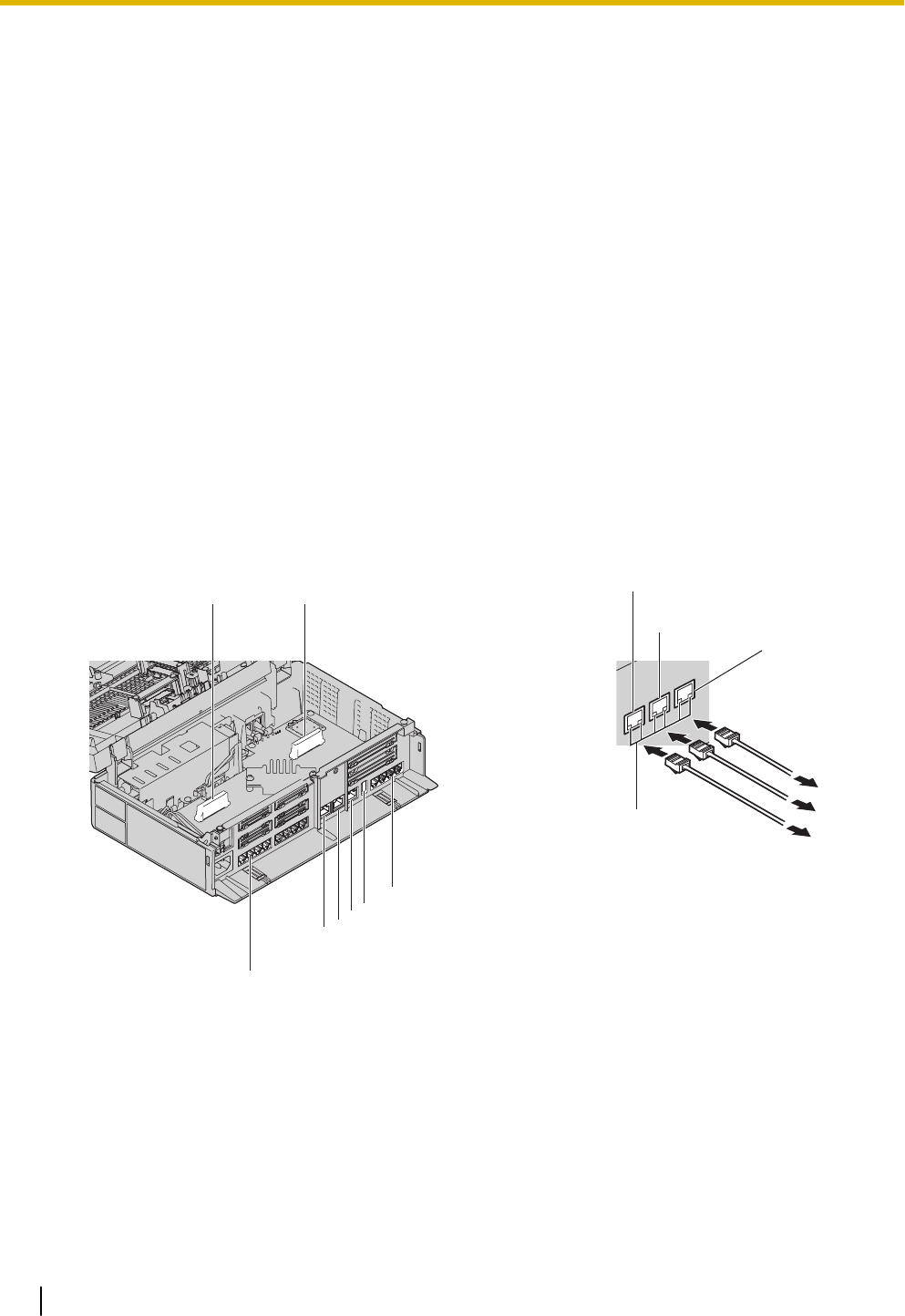
3.3 The Mother Board and Option Cards
3.3.1 Mother Board
Function
The motherboard has the following functions preinstalled.
•Support for up to 8 trunks (SIP trunks and analogue trunks combined)
•Support for up to 24 extensions (SIP extensions and analogue extensions combined)
The following types of connections are supported for connecting to SIP extensions, SIP trunks, and PCs on
private IP networks.
•LAN connection
•Wireless network connection
The following types of connections are supported for connecting to SIP trunks and external networks.
•WAN connection
Mountable Cards
•4-Port Analogue Trunk Card (refer to "3.3.2 LCOT4 Card (KX-HT82480)")
•8-Port Single Line Telephone Extension Card (refer to "3.3.3 SLC8 Card (KX-HT82470)")
•2-Port Doorphone/Door Opener Card (refer to "3.3.4 DPH2 Card (KX-HT82460)")
I
F
E
(2)
(3)
D
(1)
A B
E
G
C
DF
H
A Extension slot
B Trunk/Doorphone Free Slot
C SLT8 Interface
D LAN1 port
E LAN2 / WAN2 port
F WAN1 port
G USB Port
3.3 The Mother Board and Option Cards
60
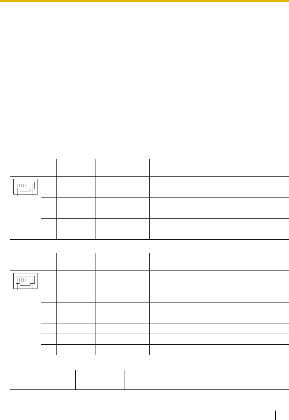
H CO4 Interface
I LEDs
(1) To LAN
(2) To LAN/WAN
(3) To WAN
Note
•The maximum length of the CAT 5/CAT 5e cables to be connected to the mother board is 100 m(328
ft).
•For details about connecting to a LAN, refer to "3.12 LAN Connection".
WARNING
A lithium battery is used in the mother board. There is a risk of explosion if the battery is replaced with
the incorrect type. Dispose of used batteries according to the manufacturer’s instructions.
Pin Assignments
LAN Port/WAN Port (10BASE-T/100BASE-TX)
No
.
Signal
Name
Input (I)/Output
(O)
Function
81
1 TPO+ O Transmit data+
2 TPO- O Transmit data-
3 TPI+ I Receive data+
4-5 Reserved - -
6 TPI- I Receive data-
7-8 Reserved - -
LAN Port/WAN Port (1000BASE-T)
No
.
Signal
Name
Input (I)/Output
(O)
Function
81
1 TRD0 (+) I/O Transmit and receive data 0 (+)
2 TRD0 (-) I/O Transmit and receive data 0 (-)
3 TRD1 (+) I/O Transmit and receive data 1 (+)
4 TRD2 (+) I/O Transmit and receive data 2 (+)
5 TRD2 (-) I/O Transmit and receive data 2 (-)
6 TRD1 (-) I/O Transmit and receive data 1 (-)
7 TRD3 (+) I/O Transmit and receive data 3 (+)
8 TRD3 (-) I/O Transmit and receive data 3 (-)
LED Indications
Indication Colour Description
STATUS Green PBX status indication
3.3.1 Mother Board
61

Indication Colour Description
•OFF: Power Off
•ON: Power On and running
•Flashing (60/minute): Starting up/Logging in
•Flashing (120/minute): Software is updating
•Flashing (240/minute): During initialisation
•Flashing (240/minute): Wi-Fi Protected Setup (WPS) in
progress
Amber PBX status indication
•Flashing (60/minute): Shutting down
•Flashing (240/minute): Initialize switch pressed
Red PBX status indication
•ON: Alarm
The cause may be one of the following:
–Alarm for an optional service card.
•Flashing (240/minute): Initialise failed
Indication Colour Description
10BASE-T/
100BASE-TX/
1000BASE-T
WAN LINK Green Link status indication
•OFF: Off-line
•ON: Linked normally
•Flashing: In communication
1000 Yellow Data transmission speed indication
•OFF: Off-line/10 Mbps/100 Mbps
•ON: 1000 Mbps
WAN/LAN LINK Green Link status indication
•OFF: Off-line
•ON: Linked normally
•Flashing: In communication
1000 Yellow Data transmission speed indication
•OFF: Off-line/10 Mbps/100 Mbps
•ON: 1000 Mbps
LAN LINK Green Link status indication
•OFF: Off-line
•ON: Linked normally
•Flashing: In communication
1000 Yellow Data transmission speed indication
•OFF: Off-line/10 Mbps/100 Mbps
•ON: 1000 Mbps
3.3.1 Mother Board
62
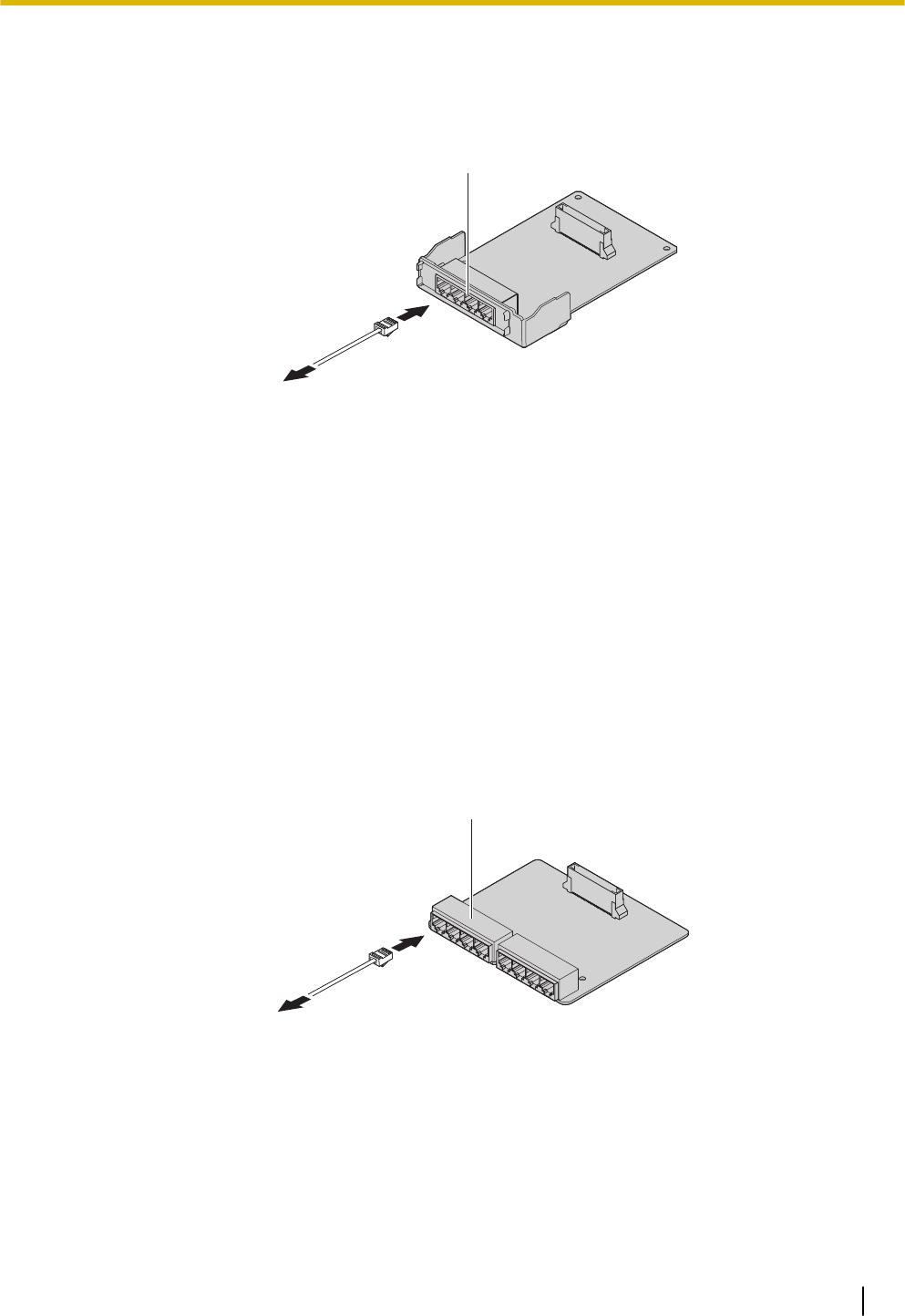
3.3.2 LCOT4 Card (KX-HT82480)
Function
4 analogue trunk ports with Caller ID (FSK/FSK with Call Waiting Caller ID [Visual Caller ID]/DTMF).
(1)
A
A RJ11
(1) To trunk
Accessories and User-supplied Items
Accessories (included): Spacer x 3, slot cover x 1
User-supplied (not included): RJ11 connector, Copper wire
Note
•Power failure Transfer feature between LCOT and SLC is not supported.
•To confirm the trunk connection, refer to "Confirming the Trunk Connection" in "3.8 Starting the
PBX".
3.3.3 SLC8 Card (KX-HT82470)
Function
8-port extension card for SLTs with Caller ID (FSK), Message Waiting Lamp control.
(1)
A
A RJ11
(1) To Extension
Accessories and User-supplied Items
Accessories (included): Spacer x 3, slot cover x 1
User-supplied (not included): RJ11 connector, Copper wire
Note
•Power failure Transfer feature between LCOT and SLC is not supported.
3.3.2 LCOT4 Card (KX-HT82480)
63
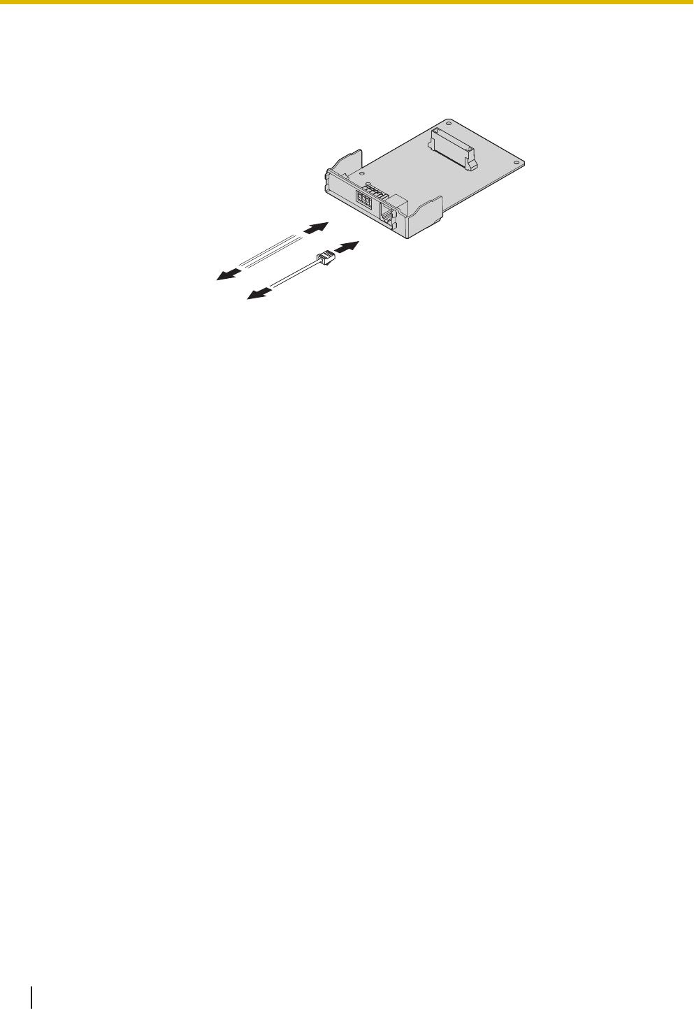
3.3.4 DPH2 Card (KX-HT82460)
Function
A doorphone card for 2 doorphone and 2 door opener.
(1)
(2)
(1) To Door opener
(2) To Doorphone
Accessories and User-supplied Items
Accessories (included): Spacer x 3, slot cover x 1
User-supplied (not included): RJ11 connector, Copper wire
Note
For details about connecting to a doorphone and/or door opener, refer to "3.6 Connecting Doorphones
and Door Openers".
3.3.4 DPH2 Card (KX-HT82460)
64
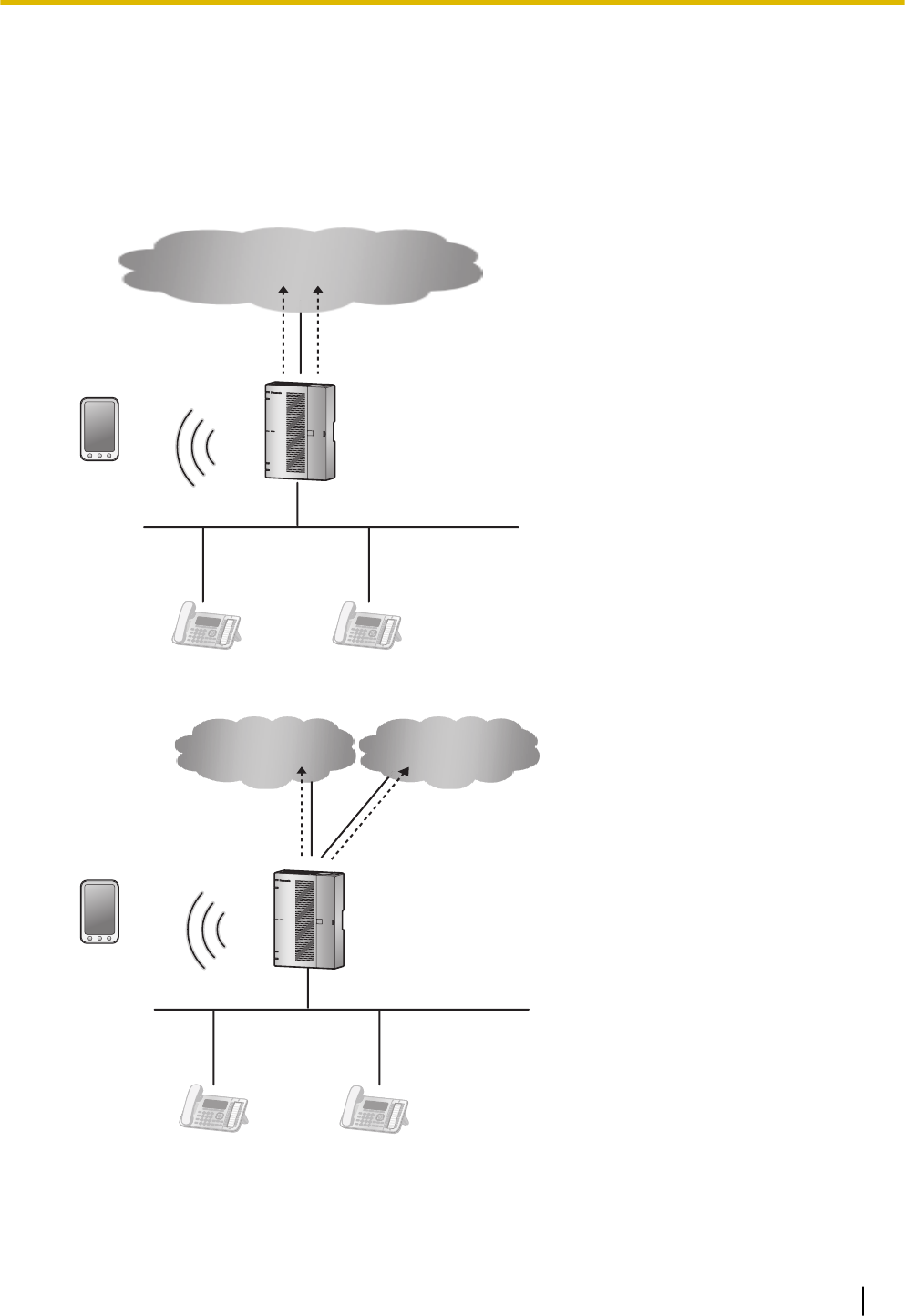
3.4 Connecting Outside Trunks
3.4.1 Connecting SIP Trunks
A typical connection example is shown below for connecting to 2 SIP carriers simultaneously. For details
about connecting SIP trunks, refer to "Network Configuration" in the Programming Item List.
1. Connecting via WAN1
SIP Phone SIP Phone
PBX
WAN1
Smartphone
(Softphone)
LAN
SIP Carrier-A SIP Carrier-B
2. Connecting via both WAN1 and WAN2
SIP Phone SIP Phone
PBX
Smartphone
(Softphone)
LAN
SIP Carrier-A SIP Carrier-B
WAN2WAN1
3.4 Connecting Outside Trunks
65
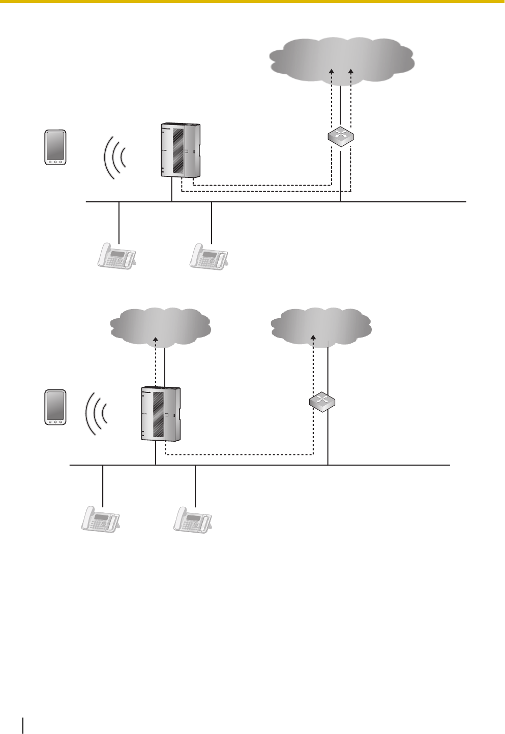
3. Connecting via an external router
SIP Phone SIP Phone
PBX
Smartphone
(Softphone)
LAN
SIP Carrier-A SIP Carrier-B
Router
WAN
4. Connecting via both WAN1 and an external router
PBX Router
SIP Carrier-A SIP Carrier-B
WAN1 WAN
Smartphone
(Softphone)
SIP Phone SIP Phone
LAN
Note
•Up to 2 SIP carriers can be connected to simultaneously.
•Trunks ports 1 through 8 can be allocated to SIP carriers.
•Each trunk port can be set to a SIP carrier or an analogue line.
•Both of the WAN ports (WAN1 and WAN2) can be used for either SIP carrier connections (pri-
vate network) or IP network connections (public network).
•To identify which LAN/WAN port is being used for each SIP carrier when both WAN1 and WAN2
are enabled, the routing information to each SIP Carrier must be retained.
3.4.1 Connecting SIP Trunks
66

3.4.2 Connecting Analogue Trunks
Connection
1. Insert the modular plugs of the telephone line cords (2-conductor wiring) into the outside (CO) line jacks.
2. Connect the line cords to the terminal board or the modular jacks from the telephone company.
Note
•Each trunk port can be set to a SIP carrier or an analogue line.
3.4.2 Connecting Analogue Trunks
67
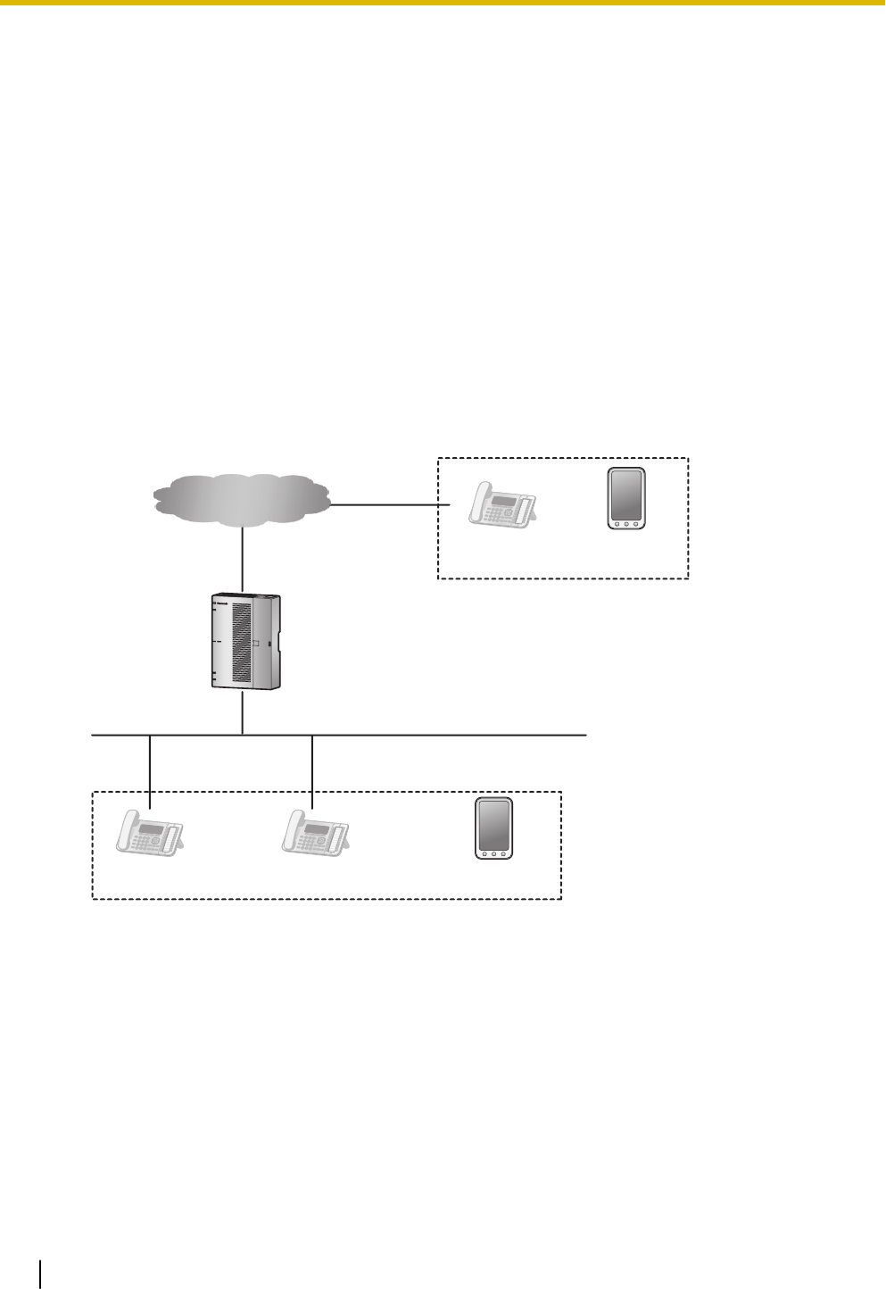
3.5 Connecting Extensions
3.5.1 Connecting SIP Extensions
A typical connection example for SIP extensions is shown below.
The following features can be used with the connection example shown below.
1. Setting IP addresses of SIP phone (automatic setting by DHCP)
2. Setting the IP address and port of the connection destination main unit (automatic setting by DHCP Op-
tion 66)
3. Acquisition of SIP phone configuration data (distributed by main unit via HTTP)
4. SIP registration to main unit (using SIP authentication data written in the configuration data)
5. Firmware update functions
a. To connect to the Internet via the internal router
1-1: LAN connection of internal router
1-2: Connection via WAN of internal router
PBX
LAN
Internet
WAN
1-1
SIP Phone
1-2
Smartphone
(Softphone)
SIP PhoneSIP Phone Smartphone
(Softphone)
b. To connect to the Internet via an external router
2-1: LAN connection of external router
2-2: Connection via WAN of external router
3.5 Connecting Extensions
68
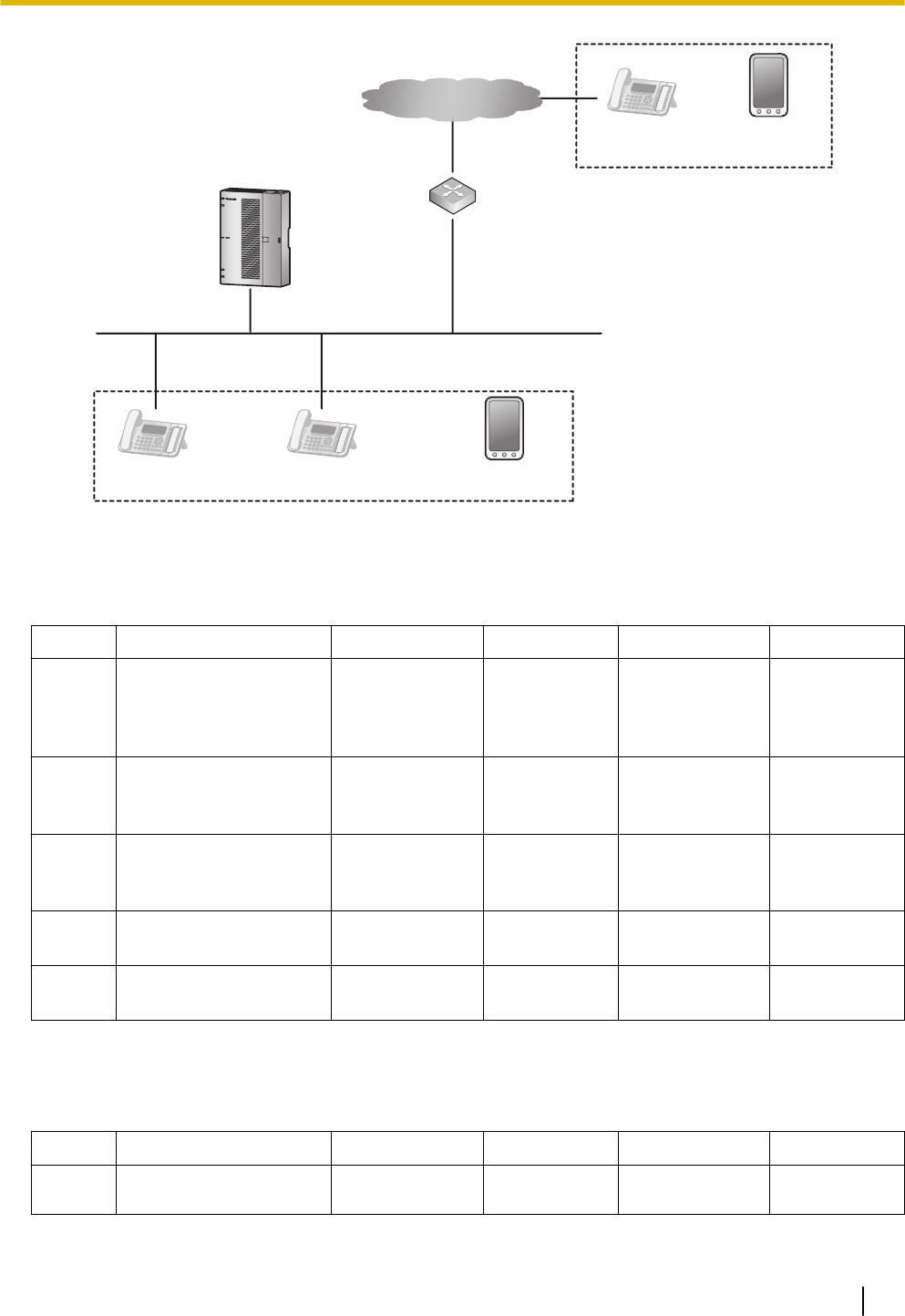
PBX
LAN
Internet
WAN
Router
2-1
SIP Phone
2-2
Smartphone
(Softphone)
SIP PhoneSIP Phone Smartphone
(Softphone)
For Panasonic SIP devices (for compatible models, see Panasonic Web site)
Relationships between registration (provisioning), firmware updates, and the installation environment are
shown below. Note that each SIP phone extension can be set for whether or not to accept connections from
outside networks.
Function 1-1 1-2 2-1 2-2
1 Setting IP addresses to
SIP phones
Automatic
(DHCP)
Automatic or
manual
(Depends on
environment)
Automatic or
manual
(Depends on
environment)
Automatic or
manual
(Depends on
environment)
2 IP address and port
settings for connection
destination main unit
Automatic
(DHCP Option
66)
N/A Manual
(Phone's web
settings)
N/A
3 Acquisition of SIP
phone configuration
data
Automatic
(SIP/HTTP)
N/A Automatic
(SIP/HTTP)
N/A
4 SIP registration to main
unit
Automatic
(SIP)
Manual*1*2
(SIP)
Automatic
(SIP)
Manual*1 *3
(SIP)
5 Firmware update Automatic
(SIP/HTTP)
N/A Automatic
(SIP/HTTP)
N/A
*1 For general SIP phones, the SIP server address and port settings of the HTS824 are required.
*2 Port forwarding settings for the SIP ports of the HTS824 internal router are required.
*3 Port forwarding settings for the SIP ports of the external router are required.
For non-Panasonic SIP devices
The relationships of the setting environment are shown below.
Function 1-1 1-2 2-1 2-2
1 Setting IP addresses to
SIP phones
Automatic
(DHCP)
Automatic or
manual
Automatic or
manual
Automatic or
manual
3.5.1 Connecting SIP Extensions
69

Function 1-1 1-2 2-1 2-2
(Depends on
environment)
(Depends on
environment)
(Depends on
environment)
2 IP address and port
settings for connection
destination main unit
N/A N/A N/A N/A
3 Acquisition of SIP
phone configuration
data
N/A N/A N/A N/A
4 SIP registration to main
unit
Manual *1
(SIP)
Manual*1 *2
(SIP)
Manual *1
(SIP)
Manual *1*3
(SIP)
5 Firmware update N/A N/A N/A N/A
*1 For general SIP phones, the SIP server address and port settings of the HTS824 are required.
*2 Port forwarding settings for the SIP ports of the HTS824 internal router are required.
*3 Port forwarding settings for the SIP ports of the external router are required.
3.5.2 LAN Connections for IP Telephones
When an IP telephone is connected to the LAN and power is supplied for the first time, you will be prompted
to set network parameters. The network parameters must be set for the IP telephone before it can be used.
Connecting an IP Telephone to a Switching Hub
When connecting an IP telephone to the LAN, connect it to a switching hub.
Note
•Use an Ethernet straight cable with an RJ45 connector to connect the IP telephone to a switching
hub. The cable should be a CAT 5 (Category 5) or higher for 10BASE-T/100BASE-TX, or CAT 5e
(Enhanced Category 5) or higher for 1000BASE-T.
•When using the VLAN feature on the network, make sure that the switching hub to be connected is
IEEE 802.1Q compliant and is configured for VLANs. In addition, the port of a switching hub that the
IP telephone is connected to must be set to "Trunk" port, to allow VLAN tagging. Consult your net-
work administrator for details.
•Since an IP softphone is installed and operates on a PC, the PC must be connected to the LAN to
use the IP softphone on the network.
The diagram below is for connecting an P-SIP to a switching hub. For SIP phones, refer to the documenta-
tion of your SIP phone.
Example: KX-HDV230
3.5.2 LAN Connections for IP Telephones
70
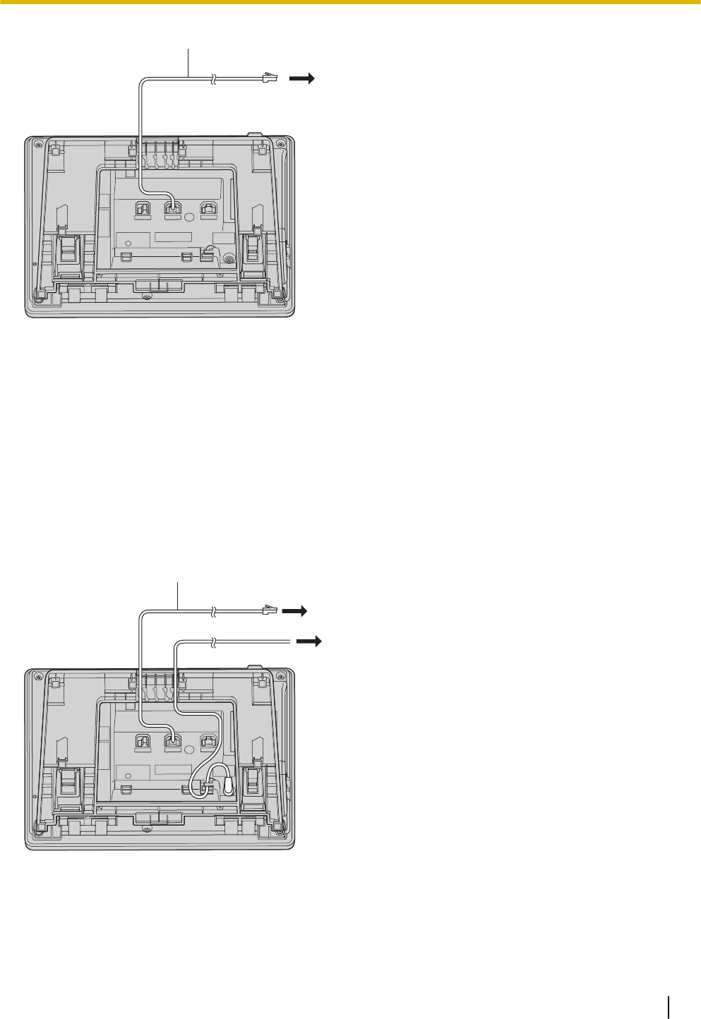
A
(1)
A Ethernet Straight Cable
(1) To a Switching Hub
Connecting an AC Adaptor to an IP Telephone
Some SIP phones comply with the IEEE 802.3af Power-over-Ethernet (PoE) standard. If PoE is available on
your network, these IP telephones can receive the necessary power supply from the network through the
network cable. In this case, an AC adaptor is not needed for the IP telephone. However, if PoE is not availa-
ble, you will need to connect an AC adaptor to the IP telephone.
Note
Use only the specified type of AC adaptor for each IP telephone. For details, refer to the documentation
of your IP telephone.
Example: KX-HDV230
A
(1)
(2)
A Ethernet Straight Cable
(1) To a Switching Hub
(2) To Wall Socket
3.5.2 LAN Connections for IP Telephones
71
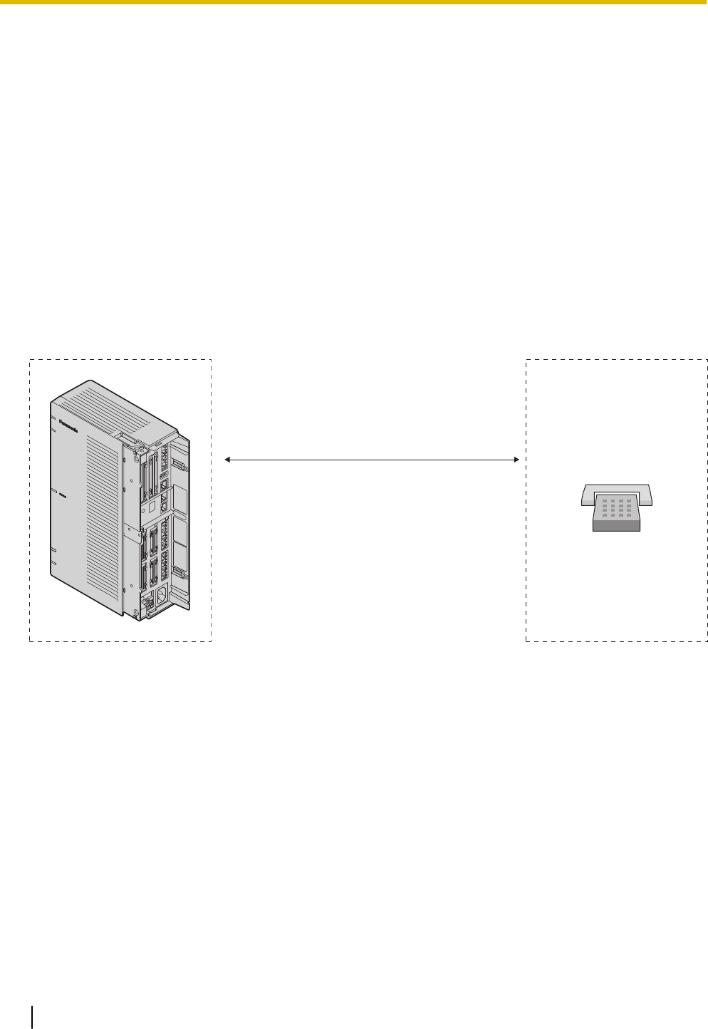
Connecting a PC to an IP Telephone
You can connect a PC to some IP telephones using the IP telephone’s secondary port. In this case, only a
single port from the LAN’s network interface (switching hub) is required to connect both the IP telephone
and PC to the LAN.
Note
•Use an Ethernet straight cable with an RJ45 connector to connect a PC to the IP telephone. The
cable should be a CAT 5 (Category 5) or higher for 10BASE-T/100BASE-TX, or CAT 5e (Enhanced
Category 5) or higher for 1000BASE-T.
•Only a PC can be connected to the secondary port of an IP telephone. Other IP telephones or net-
work devices such as routers or switching hubs, cannot be connected.
•In cases where a PC is connected to the secondary port, if the IP telephone connection to the PBX
is disconnected or reset, LAN communication to the PC will also be disrupted.
3.5.3 Connecting Analogue Extensions Maximum Cabling
Distances of the Extension Wiring (Twisted Cable)
Cable
ø 0.4 mm (26 AWG):
ø 0.5 mm (24 AWG):
ø 0.6 mm (22 AWG):
Maximum
Distance
698 m (2289 ft)
1128 m (3700 ft)
1798 m (5898 ft)
A
A SLT
Notice
The maximum cabling distance may vary depending on the conditions.
3.5.3 Connecting Analogue Extensions Maximum Cabling Distances of the Extension Wiring (Twisted Cable)
72
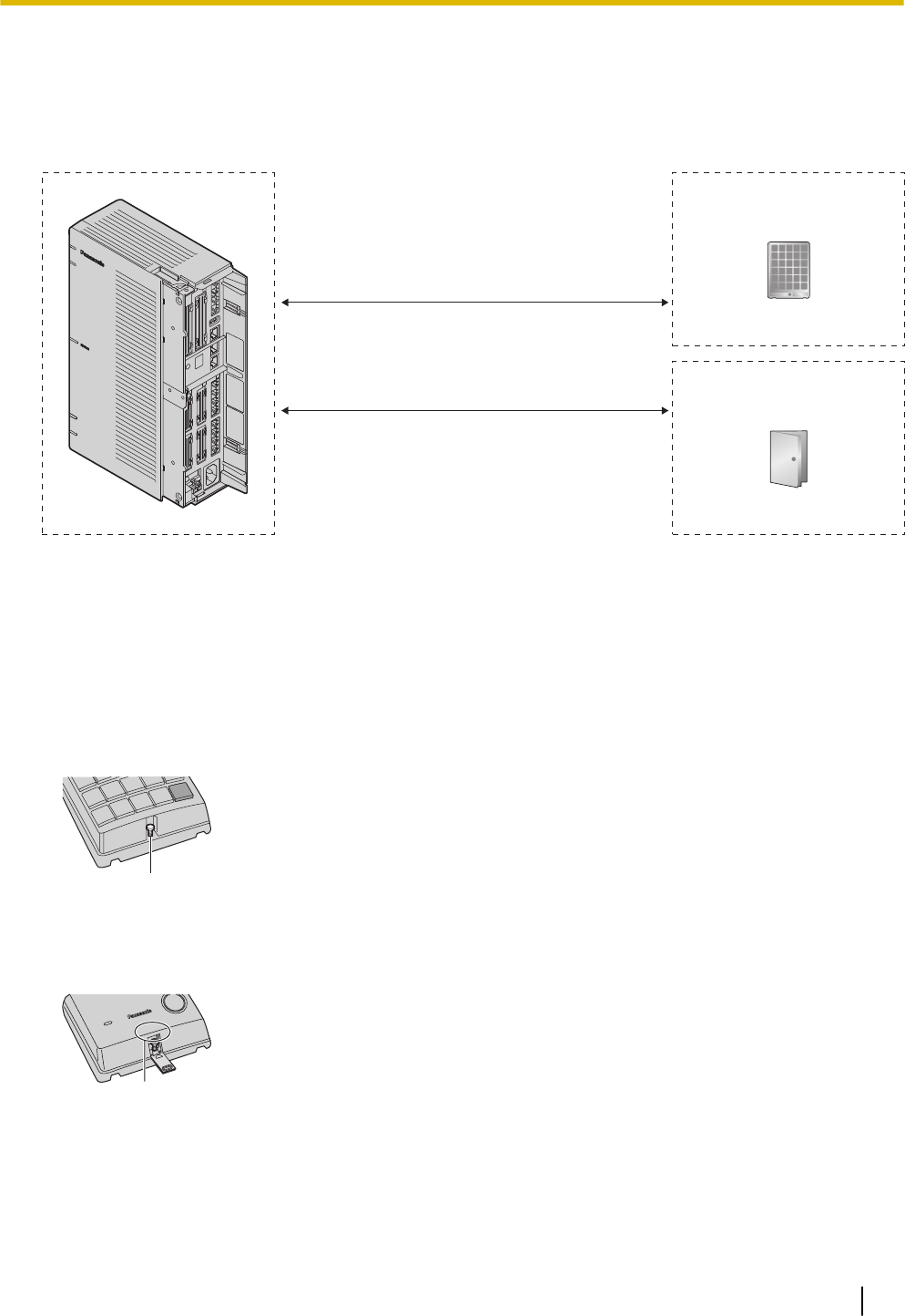
3.6 Connecting Doorphones and Door Openers
Up to 2 doorphones (KX-T30865) and 2 door openers (user-supplied) can be installed.
Maximum Cabling Distance
Cable
ø 0.42 mm (25 AWG):
ø 0.5 mm (24 AWG):
ø 0.6 mm (22 AWG):
Maximum
Distance
70 m (230 ft)
113 m (371 ft)
180 m (590 ft)
A
B
Cable
ø 0.65 mm (22 AWG):
Maximum
Distance
150 m (492 ft)
A Doorphone
B Door Opener
Door opener current limit: 30 V DC/30 V AC, 3 A maximum
Installing the Doorphone (KX-T30865/KX-T7765)
Note
The illustrations shown in the installation procedure are based on the KX-T30865.
1. Loosen the screw to separate the doorphone into 2 halves.
Panasonic
A
A Screw
Note for KX-T7765 Users
When loosening/tightening the screw, do not scratch the cabinet wall with the driver shaft.
B
B Cabinet Wall
2. Pass the wires through the hole in the base cover, and attach the base cover to a wall using 2 screws.
3.6 Connecting Doorphones and Door Openers
73
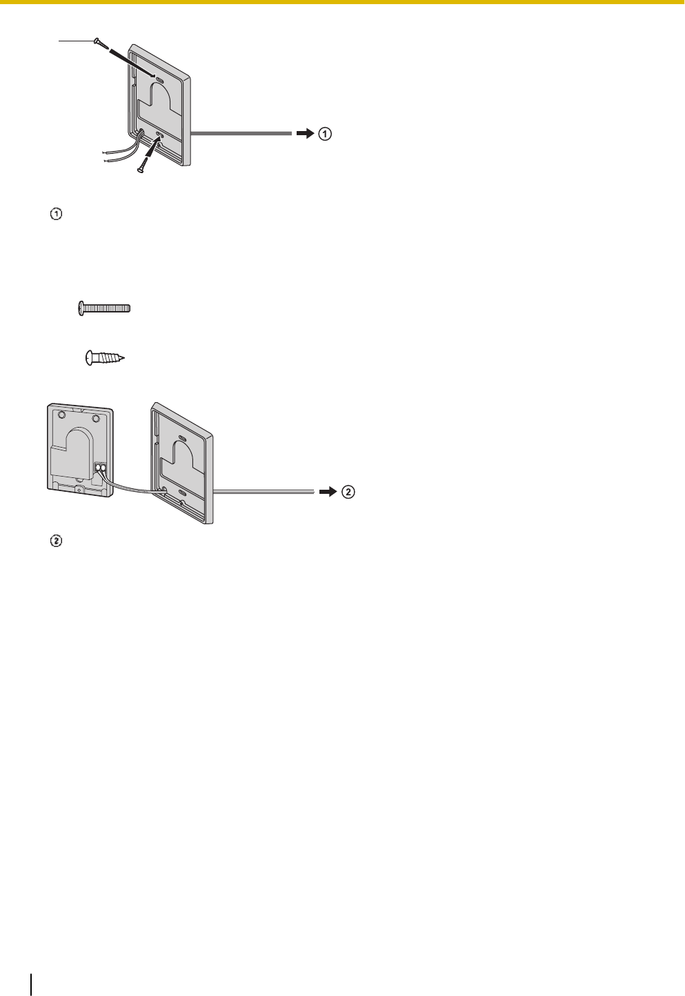
B
B Screw
To DPH2 Card
Note
Two kinds of screws are included with the doorphone. Please choose the appropriate kind for your
wall type.
: when a doorphone plate has been fixed to the wall
: when you wish to install the doorphone directly onto the wall
3. Connect the wires to the screws located in the back cover.
To DPH2 Card
4. Re-attach the 2 halves and re-insert the screw.
Connecting Doorphones (KX-T30865/KX-T7765)
1. Connect the doorphone card to the terminal box using 4-conductor wiring and modular connectors.
2. Connect the wires of doorphone 1 to the red and green screws on the appropriate terminal box.
3. Connect the wires of doorphone 2 to the yellow and black screws on the appropriate terminal box.
3.6 Connecting Doorphones and Door Openers
74
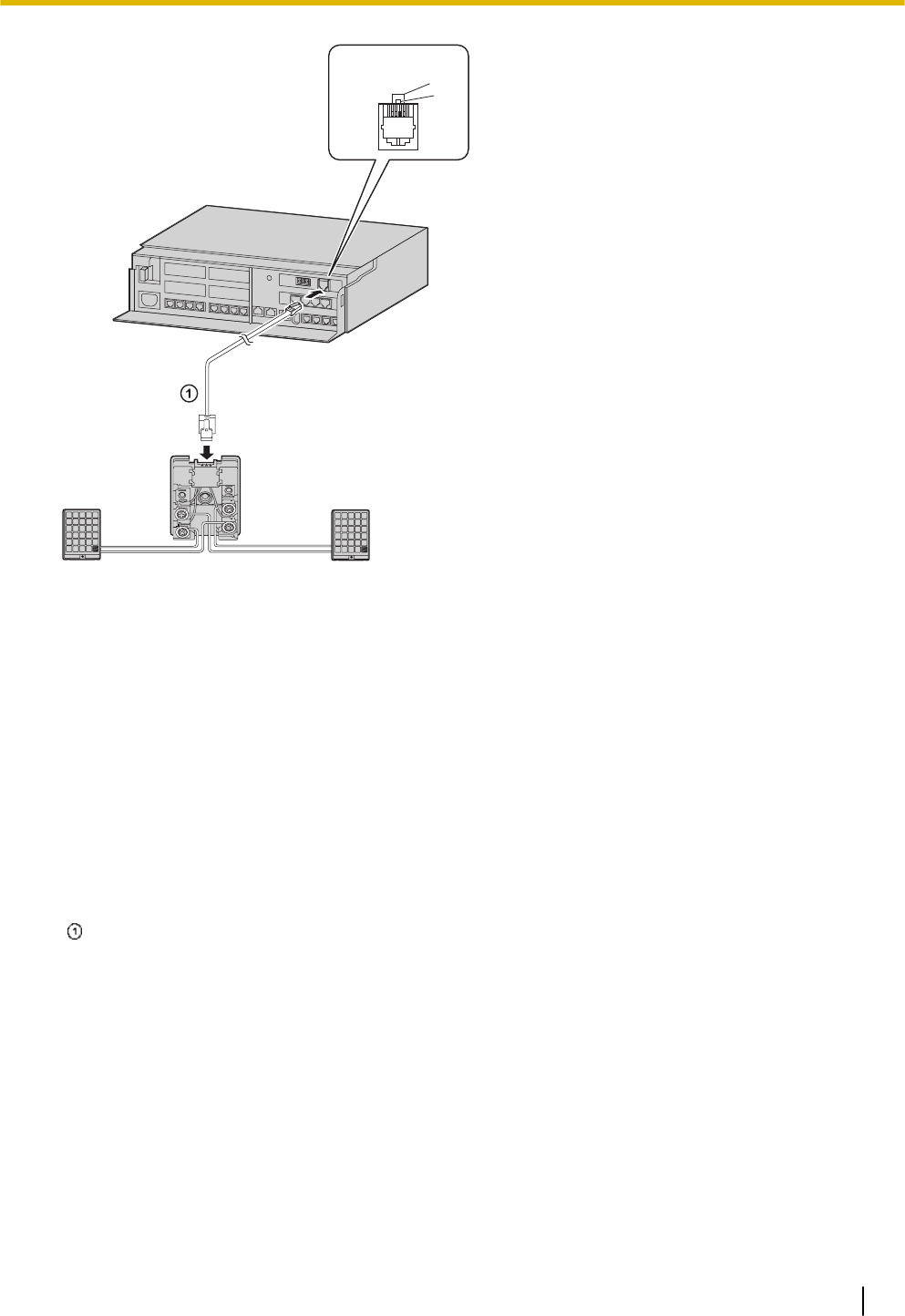
Panasonic Panasonic
D
E
F
G
H
I J
B
C
A
A View of Doorphone Connector Jack
B Doorphone 2
C Doorphone 1
D Terminal Box
E Yellow
F Red
G Black
H Green
I Doorphone 1
J Doorphone 2
4-conductor wiring is required.
Connecting Door Openers
1. Use a flathead screwdriver to press and hold open the button below the terminal, and insert the wire
coming from the door opener into the terminal.
3.6 Connecting Doorphones and Door Openers
75
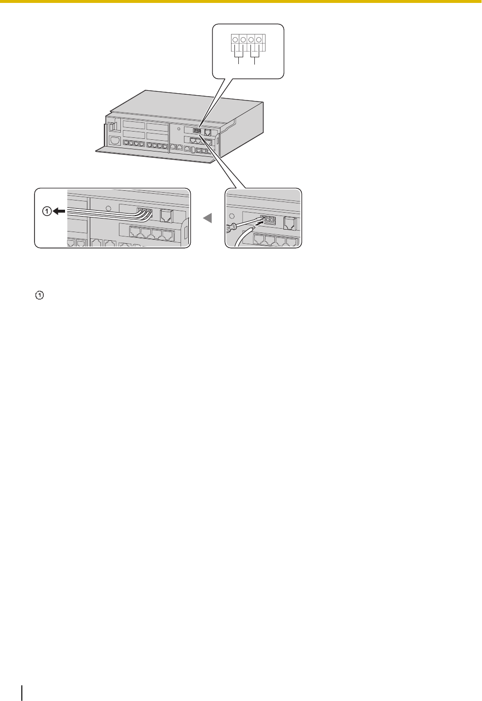
A B
A Door Opener 2
B Door Opener 1
To the door openers
2. Wrap the strap around all of the cords. (For details, refer to "3.2.6 Securing the Cables".)
Note
•We recommend using UL1015 wire or an equivalent for wiring. For users in except in U.S.A.
•The wire should be between 0.45 mm and 1.1 mm in diameter excluding the coating. For users
in U.S.A only
•We recommend using UL1015, 26 AWG to 22 AWG, or an equivalent wire for wiring.
3.6 Connecting Doorphones and Door Openers
76
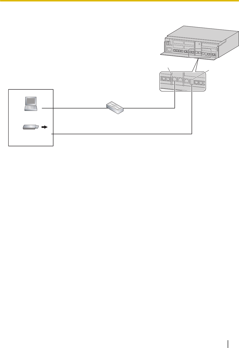
3.7 Connection of Peripherals
LAN Port
USB Port
PC Switching Hub
Maximum Distance
100 m (328 ft)
Maximum Distance
100 m (328 ft)
Maximum Distance 5 m (16 ft)
USB Memory Device
3.7.1 USB Interface for USB Memory Device
The PBX is equipped with a USB 2.0 interface. This interface provides communication between the PBX
and user-supplied devices such as a USB memory device.
Using a USB memory device
A USB memory device can be used to backup and restore the system data of the PBX.
The PBX supports USB memory devices that meet the following specifications:
•File system: FAT
•Maximum capacity: 32 GB
•Maximum current: 500 mA
For details about backing up and restoring using a USB memory device, refer to "6.1 Tool—System Data
Backup" in the Programming Item List.
Note
Do not use a USB hub when connecting a USB memory device to the PBX.
3.7 Connection of Peripherals
77
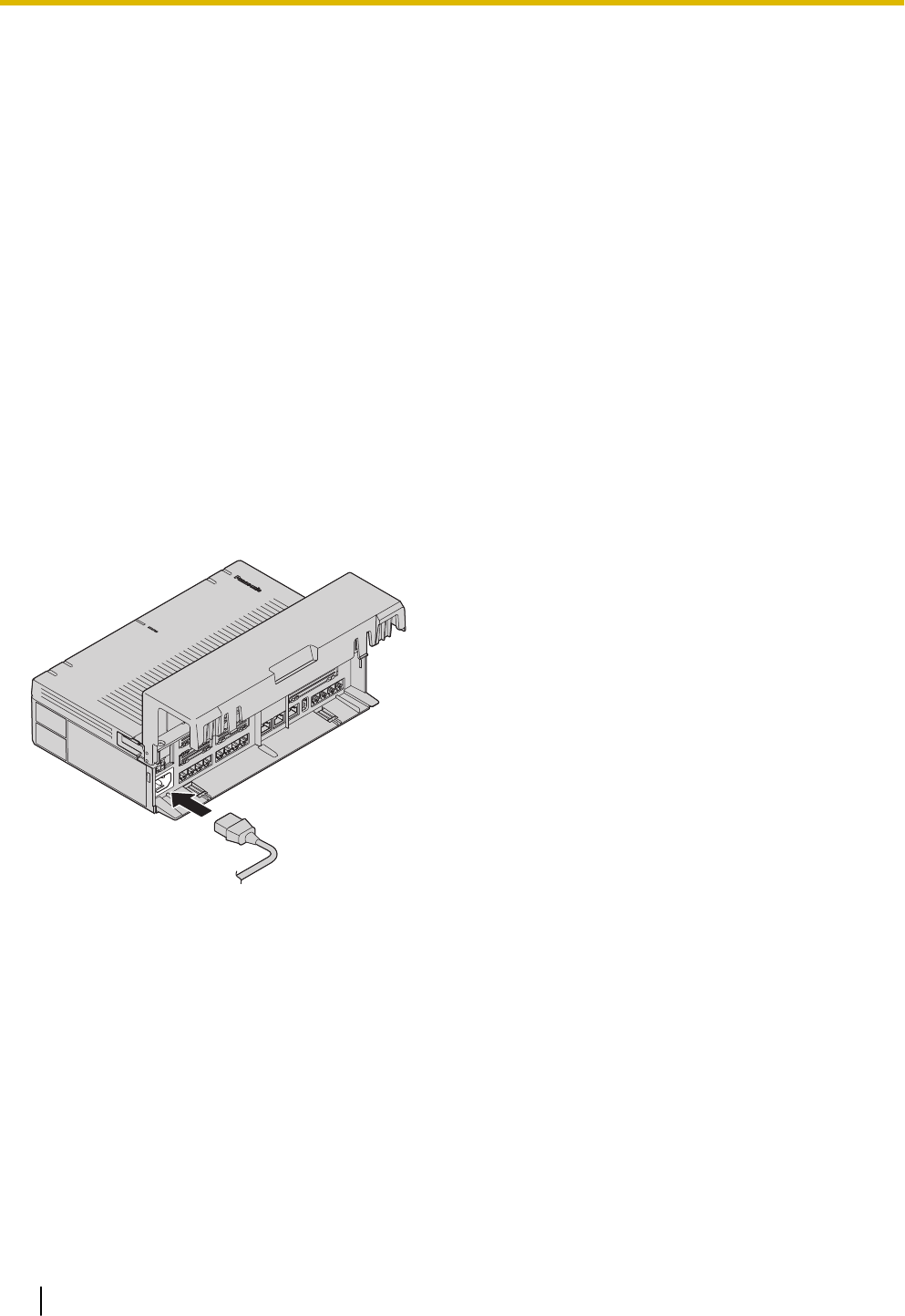
3.8 Starting the PBX
WARNING
Make sure that the AC outlet is properly earthed, then securely connect the 3-pin AC plug including the
earthed pin.
CAUTION
•Use only the AC power cord included with the PBX.
•Before touching the product (PBX, cards, etc.), discharge static electricity by touching ground or
wearing an earthing strap. Failure to do so may cause the PBX to malfunction due to static electrici-
ty.
•Once you have started the PBX, if you unplug the PBX, do not initialise it again as described in
"System Initialisation Procedure". Otherwise, your programmed data will be cleared. To restart the
PBX, refer to "6.1.4 Restarting the PBX".
•The plug of power supply cordset is used as the main disconnect device. Ensure that the AC outlet
is located near the equipment and is easily accessible.
Connecting the AC Power Cord
Note
For safety reasons, do not stretch or pinch the AC power cord.
System Initialisation Procedure
The system can be reset to its original default state by pressing the Initialize switch while turning the system
power on.
The system initialisation startup operation is as follows.
•Turn on the system power and press and hold the Initialize switch (for 3 seconds).
1. Initialize switch press and hold (3 seconds) recognised: Green (high-speed flashing at 120 flashes/
minute)
2. Initialize switch press and hold (3 seconds) confirmed: Amber (flashes 3 times)
3. Initialise process and system startup process: Green (low-speed flashing at 60 flashes/minute)
•When system initialisation is complete, operation begins (green LED illuminated).
Performing a system initialisation returns the system data to its default settings.
The memory state is also cleared.
3.8 Starting the PBX
78
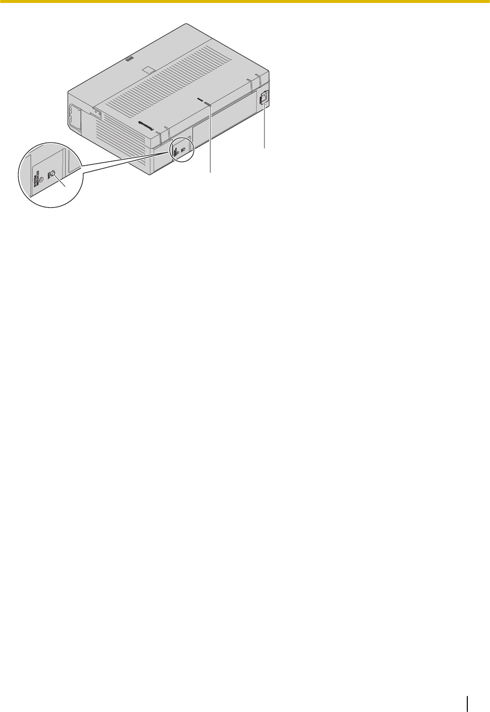
C
B
A
A Initialize switch
B STATUS Indicator
C Power switch
Note
•After the PBX is initialised, you can restore system data to the PBX that has been backed up earlier.
For details about backing up and restoring system data, refer to "Maintenance-[2-3]System Control-
System Data Backup & Restore" in the Programming Item List." in the Programming Item List.
•After the PBX is initialised, you must set up the mandatory settings required for the PBX with Easy
Setup Wizard. For details refer to "Connecting to Web Maintenance Console" and "3.9.4.1 Easy Set-
up Wizard".
•When a Backup Batteries is connected, make sure it is started as instructed in the documentation for
the Backup Batteries.
Confirming the Trunk Connection
After the PBX starts up, programme the PBX and connect trunks to the PBX.
To confirm that the trunks are successfully connected, dial [*] [3] [7] + trunk number (3 digits) on an IP tele-
phone, or press the IP telephone’s S-CO button. You will hear a dial tone if the trunk is available and con-
nected.
3.8 Starting the PBX
79
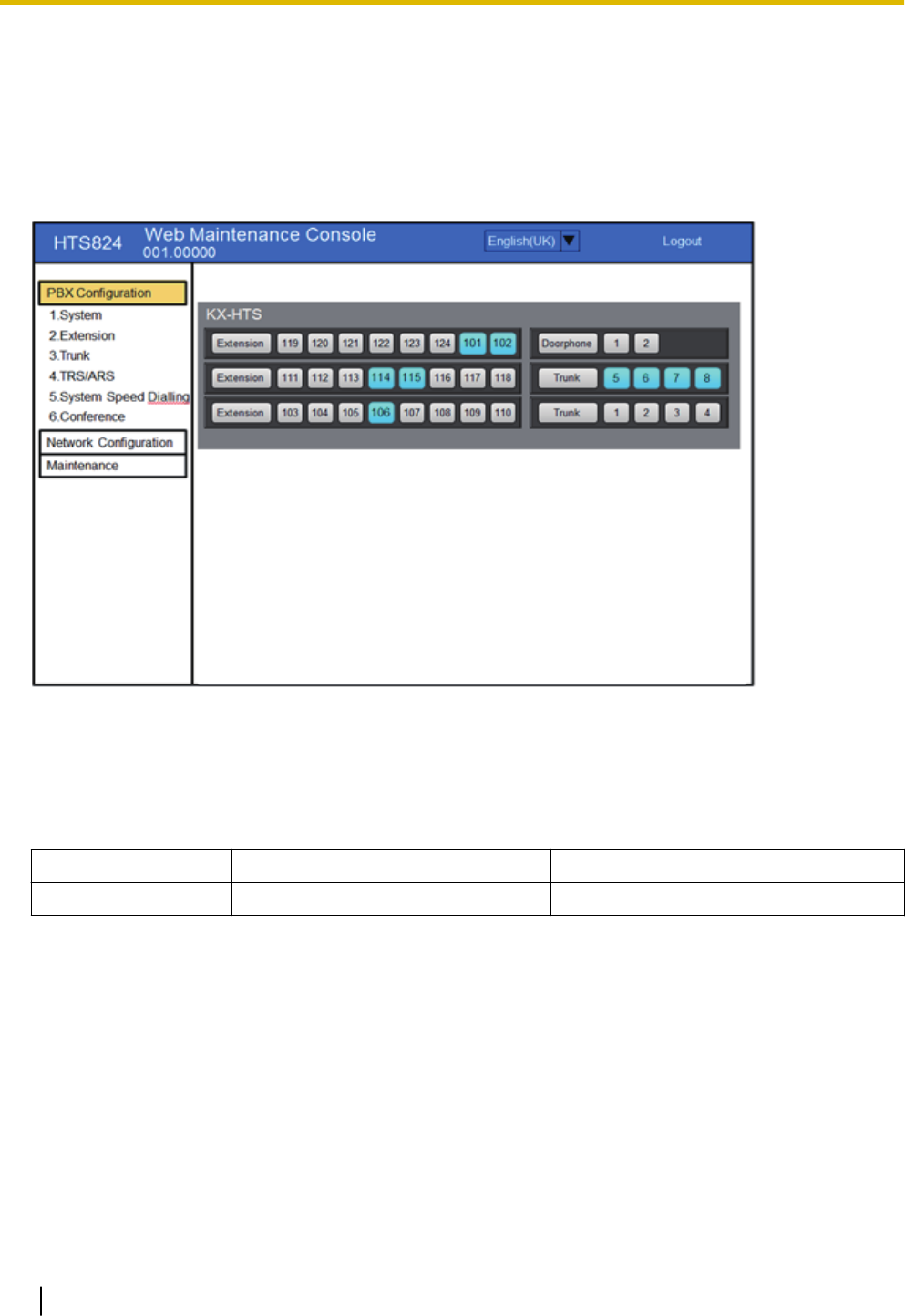
3.9 Programming Information
3.9.1 Overview of Web Maintenance Console
Web Maintenance Console is designed to serve as an overall system programming reference for the PBX.
You can programme and control the PBX over an IP network using Web Maintenance Console.
This section describes programming basic items using Web Maintenance Console.
スクリーンショット待ち
Note
The contents and design of the software are subject to change without notice.
3.9.2 PC Connection
The Main Unit has a LAN port for PC to programme PBX. A PC can be connected through LAN connection.
Port Default IP Address Default Subnet Mask
LAN Port 192.168.0.101 255.255.255.0
3.9 Programming Information
80
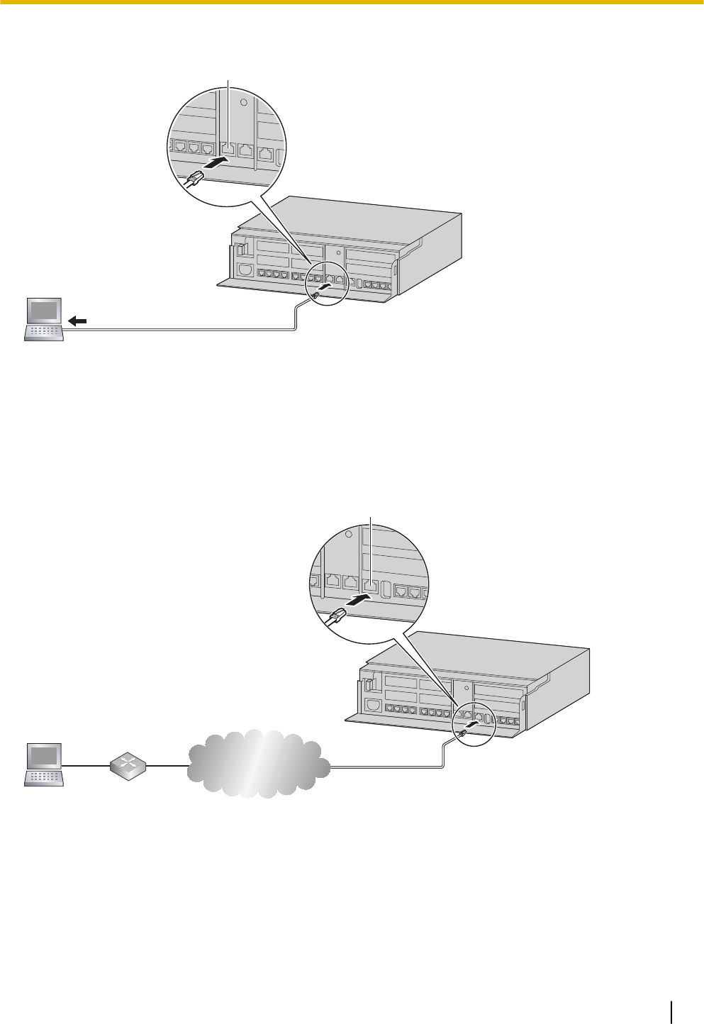
3.9.2.1 Direct Connection
To LAN Port
LAN Port
Notice
When connecting the PC to the LAN port, if the PC is set to obtain the IP address automatically, the IP
address of the PC will be set to an appropriate IP address to establish a connection to the PBX.
Note
•Use an Ethernet cable with an RJ45 connector to connect a PC to the PBX.
Connection via Internet
Router
Internet
PC
WAN Port
CAUTION
It is strongly recommended to use TLS encrypted communication when the PC is accessing the PBX via
the Internet. To use TLS encryption, routers must have a port set up for https communication.
Note
For details about connecting a switching hub to the PBX, refer to "3.13 WAN Connection".
3.9.2 PC Connection
81

3.9.3 Starting Web Maintenance Console
System Requirements
For the system requirements of the PC (operating system, hardware specifications, supported browsers
etc.), refer to "3.9.3 Starting Web Maintenance Console" in the Programming Item List.
Copyright for MD5
This software uses the Source Code of RSA Data Security, Inc. described in the RFC1321 (MD5 Message-
Digest Algorithm).
Copyright (C) 1991-2, RSA Data Security, Inc. Created 1991. All rights reserved.
Licence to copy and use this software is granted provided that it is identified as the "RSA Data Security, Inc.
MD5 Message-Digest Algorithm" in all material mentioning or referencing this software or this function.
Licence is also granted to make and use derivative works provided that such works are identified as "de-
rived from the RSA Data Security, Inc. MD5 Message-Digest Algorithm" in all material mentioning or refer-
encing the derived work.
RSA Data Security, Inc. makes no representations concerning either the merchantability of this software or
the suitability of this software for any particular purpose. It is provided "as is" without express or implied war-
ranty of any kind.
These notices must be retained in any copies of any part of this documentation and/or software.
Connecting to Web Maintenance Console
1. Connect the PC to the PBX:
•Connect the PBX to a network with the LAN port and access the PBX from a PC in your LAN. For
details, refer to "3.9.2 PC Connection".
2. Access Web Maintenance Console:
LANConnection: Launch your Web browser and input the IP address of the PBX followed by the Web
Maintenance Console port number into the address bar. The input method will differ according to the
PC’s connection to the PBX. The default IP address for the LAN port of the PBX is 192.168.0.101, and
the default Web Maintenance Console port number is 80. Accordingly, the address to enter to connect to
the PBX for the first time will be as follows (enter the address exactly as shown):
http://192.168.0.101
Note
•The default subnet mask for the LAN port is 255.255.255.0.
Internet Connection (TLS Connection):
When the PC is accessing the PBX from a connection over the internet, the use of TLS is strongly rec-
ommended. When using a TLS encrypted connection, the default port is 443. The format of the address
to enter to connect to the PBX using a TLS encrypted connection will be as follows:
https://xxx.xxx.xxx.xxx:yyy
•"xxx.xxx.xxx.xxx" is the IP address of a device that can be accessed from the Internet, such as the
IP address of a network router.
•"yyy" is a port number. The network router’s port forwarding settings must be configured so that traf-
fic arriving at port "yyy" is forwarded to the correct IP address and port of the PBX in the LAN.
•Port forwarding settings must specify the IP address and the port number of the network router
("xxx.xxx.xxx.xxx:yyy") to transfer the packets to the PBX in the LAN, so that the packets sent to the
global IP address and specified port of the router will be transferred to the IP address and specified
port of the PBX in the LAN.
•Note the usage of "https" instead of "http".
•If you connect to Web Maintenance Console using TLS, a security alert window is displayed. Follow
the prompts to install a security certificate. The procedure may vary according to your browser.
3.9.3 Starting Web Maintenance Console
82

3. The Web Maintenance Console login screen is displayed. Log in with the Installer level account name
and the default Installer level account password to launch the Easy Setup Wizard. For details about the
Easy Setup Wizard, see "3.9.4.1 Easy Setup Wizard".
3.9.4 Programming the PBX
3.9.4.1 Easy Setup Wizard
In the Easy Setup Wizard, you will set up the mandatory settings required for the PBX.
When you log in to Web Maintenance Console for a PBX that is in its initialised, factory default state, the
Easy Setup Wizard for that PBX will launch automatically. You must log in using the Installer level account
name and password.
–The Installer level account name is "INSTALLER".
–The default Installer level account password is "1234".
Set the following items in the setting screens.
1. 1. Web MC Language
2. Date & Time
3. Line Access/Operator No.
4. LAN Setting
3.9.4 Programming the PBX
83

3.10 Date and Time setting
The following items can be set for the date and time settings. For details about date and time settings, refer
to "PBX Configuration-[1-1]System-Date & Time-◆Date & Time" in the Programming Item List.
•Automatic Time Adjustment
•Daylight Saving Adjustment
•Daylight Saving Time
•Time Zone
3.10 Date and Time setting
84

3.11 Network and Router Function
Following table describes networking functions and router functions. For details about data and time set-
tings, refer to "2.1.1 PBX Configuration-[1-1]System-Date & Time" in the Programming Item List.
Functions Description
WAN Interface 10/100/1000 Mbps Ethernet
LAN (Wired) Interface 10/100/1000 Mbps Ethernet
Wireless LAN Interface IEEE 802.11b/g/n
WLAN WEP64,WEP128/WPA/WPA2/MixedWPA/WPA2
Automatic WLAN
Channel Selection
Yes
WLAN Associations
Filtering (ACL)
Yes (per SSID basis)
WPS (Wi-Fi Protected
Setup)
Yes
Link Layer Protocols
PPP Point-to-Point Protocol (PPP)
PPP in HDLC-like Framing
Link Control Protocol (LCP)
Compression Control Protocol (CCP)
PPP Internet Protocol Control Protocol (IPCP)
PPP Authentication Protocols (PAP)
PPP Challenge Handshake Authentication
Protocol (CHAP)
MS-CHAP v1/MS-CHAP v2
PPP Encryption Control Protocol (ECP)
PPPoE
PPP Connection Keep Alive
PPP DialOn Demand
PPPoE relay from LAN Ethernet over WAN
Ethernet
Bridging 802.1d LearningBridge and Filtering
Network Layer
Protocols
IPv4 Networking Yes (IPv6 is not supported.)
Multicast IGMPv3 & IGMPv2
–Proxy
–Snooping
–Host
Network Core
Functions
Static Routing Yes
Firewall Packet Filtering (IPv4, MAC address, port
numbers and protocols)
Stateful Packet Inspection (SPI)
DMZ host
Basic DoS Attack Prevention
NAT/NAPT Yes
NATPass-through IPsec/IKE pass through
3.11 Network and Router Function
85

Functions Description
L2TP Pass through
Quality of Service DiffServ for IP-QoS.
AF/EF
Priority Queueing/Weighted FairQueuing (WFQ)
Random Early Discard (RED)/Drop-Tail (DT)
WLAN QoS supported through
WMM(IEEE802.11e).
Networking
Applications
DHCP DHCPv4
NTP NTP Client
DNS DNSv4
DNS Proxy or Relay Yes
DynamicDNS (DDNS) Yes
TFTP TFTP Server
FTP FTP Server
Telnet Server Telnet Server
HTTP Server HTTP-1.0, Secured-HTTP (HTTPs)
3.11 Network and Router Function
86
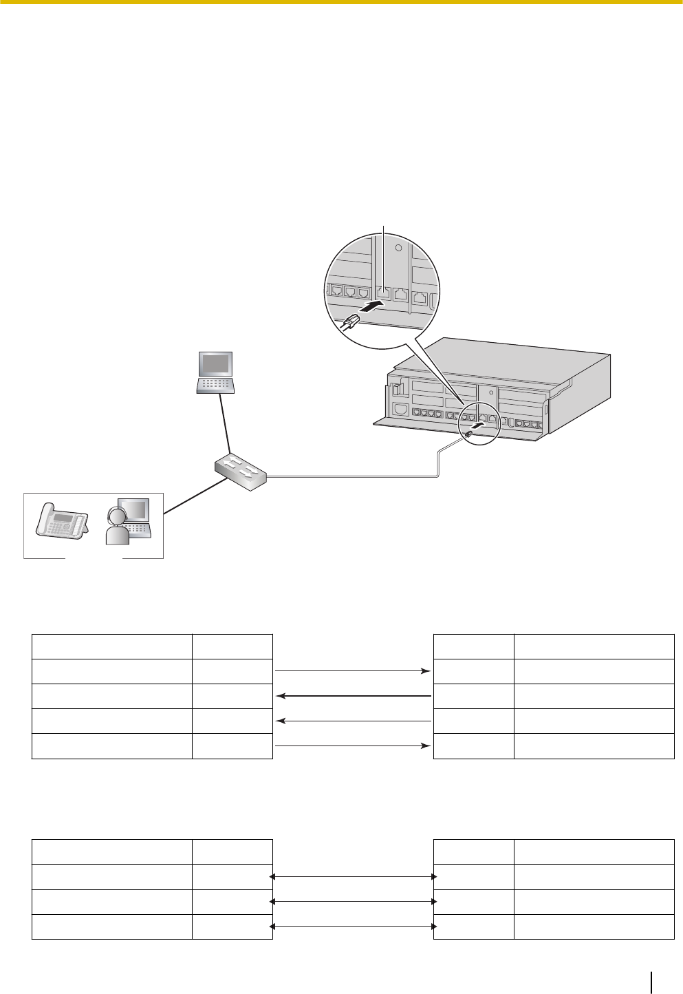
3.12 LAN Connection
3.12.1 Wired LAN Connection
The PBX is equipped with a LAN port for connecting to a LAN so that IP telephones (SIP phones) and PCs
can be connected on a private IP network. When the PBX is connected to the LAN for the first time, you
must assign IP addressing information to the PBX. See "Network Configuration" in the Programming Item
List.
Connecting the Main Unit to the Wired LAN
SIP Phone
Switching Hub
LAN Port
PC
Connection for 10BASE-T/100BASE-TX
Switching Hub PBX (LAN Port)
Signal Name Pin No. Pin No. Signal Name
TX+ 1 1 RX+
TX− 2 2 RX−
RX+ 3 3 TX+
RX− 6 6 TX−
Connection for 1000BASE-T
Switching Hub PBX (LAN Port)
Signal Name Pin No. Pin No. Signal Name
TRD0 (+) 1 1 TRD0 (+)
TRD0 (−) 2 2 TRD0 (−)
TRD1 (+) 3 3 TRD1 (+)
3.12 LAN Connection
87
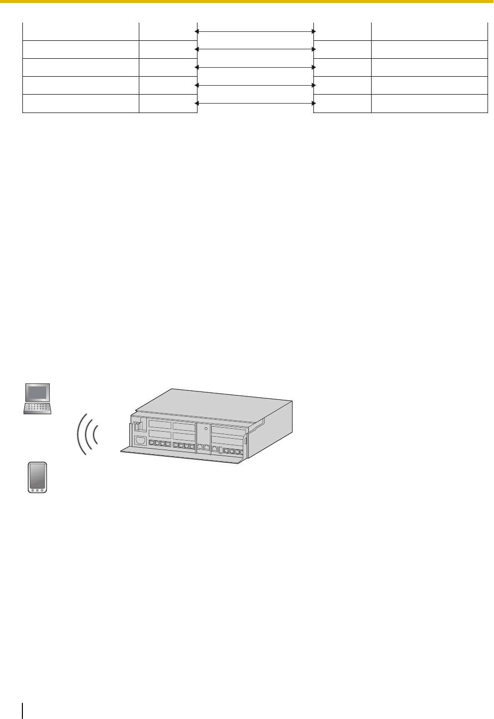
TRD2 (+) 4 4 TRD2 (+)
TRD2 (−) 5 5 TRD2 (−)
TRD1 (−) 6 6 TRD1 (−)
TRD3 (+) 7 7 TRD3 (+)
TRD3 (−) 8 8 TRD3 (−)
Note
•Use an Ethernet cable with an RJ45 connector for connection to a switching hub. The cable should
be a CAT 5 (Category 5) or higher for 10BASE-T/100BASE-TX, or CAT 5e (Enhanced Category 5)
or higher for 1000BASE-T.
•Make sure that all CAT 5/CAT 5e cables in use are not over 100 m (328 ft) in length.
•Make sure to set the port of the switching hub that connects to the card to operate under "Auto Ne-
gotiation" mode.
•Make sure to create a spanning tree for LAN connection in order to prevent loops from occurring in a
multi-bridged environment. Otherwise, some packets may circulate for long periods of time and
eventually PBX performance system may degrade.
•When using the VLAN feature on the network, make sure that the PBX is connected to a layer 2
switch that is IEEE 802.1Q compliant, and that is configured for VLANs. In addition, the port of the
switching hub to which the PBX is connected must be set to "Untagged". Consult your network ad-
ministrator for details.
3.12.2 Wireless LAN Connection
Connecting the Main Unit to the Wireless LAN
Smartphone
(Softphone)
PC
1. Perform settings for the Wireless LAN connection of the HTS Series.
Change the SSID and the Passphrase.
Also change other settings as necessary.
For details about the Wireless LAN Connection, refer to "Network Configuration-6.Wireless" in the Pro-
gramming Item List.
2. Wireless extension connections
Select one of the following connection methods for using the Wi-Fi function of the wireless extension.
a. Connection using the WPS button
•Refer to the instruction manual of the wireless extension and configure it to enable WPS.
•Press and hold the WPS button on the side of the HTS Series unit for 3 seconds. (STATUS Indi-
cator : Green flashing (240/minute) - Wi-Fi Protected Setup (WPS) in progress)
3.12.2 Wireless LAN Connection
88

•Press the WPS setting button on the wireless extension for the specified amount of time.
b. Connection using PIN code input
There is a connection method where the PIN code set at the HTS Series unit is input into the wire-
less extension, and a connection method where the PIN code set at the wireless extension is input
into the HTS Series unit. The procedure described here is for inputting the PIN code set at the HTS
Series unit into the wireless extension.
•Input the PIN code as the HTS Series' Current Router PIN. For details about the Wireless LAN
Connection, refer to "Network Configuration-6.Wireless" in the Programming Item List.
•Refer to the instruction manual of the wireless extension and register the PIN code set in the
HTS Series unit to the wireless extension.
•Click the "Connect" button of the HTS Series unit.
•Perform PIN code receiving using the wireless extension.
c. Connection using manual settings
Manually set the necessary settings on the wireless extension. Use the settings of the HTS Series
unit for setting the wireless extension's settings.
SSID
Security type
Passphrase
CAUTION
•If settings related to security are not performed, the following problems may occur.
–Transmission contents may be intercepted by a third party.
–There may be an illegal system intrusion by a third party.
Note that according to wireless LAN specifications, it is possible to break through the security settings
using special methods. Therefore, use security settings with a full understanding of them.
Note
For details about what values to use for configuring the protocol for specifying an IP address, consult the
network administrator.
3.12.2 Wireless LAN Connection
89

3.13 WAN Connection
Description
The following protocols are supported for setting the IP address of the WAN interface.
WAN Type Description
Dynamic IP Address Retrieves an IP address dynamically from your service provider.
Static IP Address Sets a static IP address.
PPPoE Obtains an IP address dynamically from a PPPoE server.
You can confirm the current connection status of the WAN interface in Web Maintenance Console.
For details about the WAN Status, refer to "Network Configuration-[3-6]WAN Status" in the Programming
Item List.
Conditions
•If the protocol for setting the IP address is changed, you must perform a System Reset and restart the
PBX before the setting can be applied.
•When the built-in router is active, it serves as the default gateway on the LAN-side of the network. The
gateway address distributed by the DHCP feature will be changed to the LAN port’s IP address.
•For details about what values to use for configuring the protocol for specifying an IP address, consult the
network administrator.
3.13 WAN Connection
90

Section 4
Confirming Connections
This section describes the basic checks and operation
methods following PBX installation for making and re-
ceiving calls to and from extensions and outside lines.
91

4.1 Making and Receiving Calls
The following is a description of the basic checks and operation methods following PBX installation for mak-
ing and receiving calls to and from extensions and outside lines.
4.1.1 Calling Another Extension
To call an extension (Intercom Call)
–Follow the operation procedure described below.
1. Off-hook. (Dial tone is heard.)
2. Dial extension number.
3. Talk
4.1.2 Calling an Outside Party
You have to seize an outside line before dialling an outside phone number because external calls are made
via your PBX.
–Follow the operation procedure described below.
1. Off-hook. (Dial tone is heard.)
2. Enter the outside line group access number (8xx). (Dial tone is not heard.)
xx : outside line group number(01-08)
Confirm all ports for the connected trunk lines.
3. Dial outside phone number.
4. Talk
4.1.3 Answering Calls
–Follow the operation procedure described below.
1. Off-hook.
2. Talk.
Note
–If a call cannot be made or answered using the above procedures, refer to "6 Troubleshooting".
4.1 Making and Receiving Calls
92

Section 5
Maintenance
This section describes maintenance procedures.
93

5.1 System Data Backup and Restore
A PBX’s system data can be backed up to a USB memory device inserted into the PBX’s USB port or to a
PC in the PBX’s LAN network. At a later time, the backed up data can be restored to the PBX.
To back up the system data to a USB memory device
•Insert a USB memory device into the USB port of the PBX.
•For details about backing up the system data to a USB memory device, refer to "Maintenance-[2-3]Sys-
tem Control-System Data Backup-◆System Data Backup" in the Programming Item List.
Note
•The USB memory device must be compatible for use with the PBX. For details, refer to
"3.7 Connection of Peripherals".
Restoring backed up data from a USB memory device to a PBX
•For details about restoring backed up data stored on a USB memory, refer to "Maintenance-[2-3]System
Control-System Data Backup-◆System Data Restore" in the Programming Item List.
Note
•Data cannot be restored in the following cases.
–The USB memory device hardware is faulty.
–The data on the USB memory device has become corrupted.
–The USB memory device is removed from the USB port of the PBX during the restoration
process.
•After a system data restore, the main unit must be restarted using the Web Maintenance Con-
sole.
To back up the system data to a PC
•For details about backing up the system data to a PC, refer to "Maintenance-[2-3]System Control-Sys-
tem Data Backup-◆System Data Backup" in the Programming Item List.
Restoring backed up data from a PC to a PBX
•For details about restoring backed up data stored on a PC, refer to "Maintenance-[2-3]System Control-
System Data Backup-◆System Data Restore" in the Programming Item List.
Note
•After a system data restore, the main unit must be restarted using the Web Maintenance Con-
sole.
Regular Automatic Backup Feature
The PBX regularly backs up the system data every 30 minutes.
The backup file is saved in the "Panasonic" folder in the internal memory of the main unit.
5.1 System Data Backup and Restore
94

5.2 Software Upgrading
Obtaining software updates (downloading the update to the PBX) can be done manually via Web Mainte-
nance Console. In this case, software updates can be obtained from a USB memory device connected to
the PBX, or a PC that can access Web Maintenance Console.
Installing an update can be done either manually via Web Maintenance Console, or on a set schedule.
The software of the following types of devices and components can be updated:
Data Type Description
Main software data Operating system data area on the PBX’s mother board.
SIP extension software data*1 Firmware of supported SIP extensions
*1 Only Panasonic telephones are supported. For details about a specific telephone, refer to the telephone's documentation.
Note
•The software version of the mother board can be confirmed through system programming.
•For details, refer to "Maintenance-[2-1]System Control-Firmware Transfer to PBX" in the Program-
ming Item List.
•For details, refer to "Maintenance-[2-2]System Control-Firmware Update to PBX" in the Program-
ming Item List.
5.2 Software Upgrading
95

5.3 System Initialisation Procedure
The system data can be returned to its initial state by following the procedure below.
1. While pressing and holding the Initialize Switch, turn the power ON. The LED will light amber.
2. Continue holding down the Initialize Switch (to confirm the holding). The LED will flash amber at a rate of
240 flashes/minute.
3. Initialization begins. The LED will flash green at a rate of 240 flashes/minute.
4. At this time the Initialize Switch may be released.
5. Operation begins in the initialised state. The LED will light green.
All data will be erased. Data that is erased includes Unified Messaging data, call logs, etc. The settings
for the PBX as well as all optional service cards will be initialised to their default values.
Note
•After the PBX is initialised, you can restore system data to the PBX that has been backed up
earlier. For details about backing up and restoring system data, refer to "5.1 System Data Back-
up and Restore".
•After the PBX is initialised, you must set up the mandatory settings required for PBXs. For de-
tails refer to "3.9.4.1 Easy Setup Wizard".
5.3 System Initialisation Procedure
96

Section 6
Troubleshooting
This section provides information on the PBX and tele-
phone troubleshooting.
97

6.1 Troubleshooting
6.1.1 Installation
PROBLEM PROBABLE CAUSE SOLUTION
You cannot make/receive
calls via an IP network.
•Mother board
malfunction
•Replace the mother board (be sure to turn
off the PBX when replacing).
•Poor connection •Make sure that an 8-pin twisted pair cable
is used for connection.
•Make sure that none of the CAT 5/CAT 5e
cables in use are over 100 m (328 ft) in
length.
•Make sure that a straight cable is used for
connection to a switching hub.
•Network malfunction •Make sure that all network devices in use
are switched on.
•Make sure that there is no unwanted
firewall in the IP network.
SIP phones do not operate. •Mother board
malfunction
•Replace the mother board (be sure to turn
off the PBX when replacing).
•SIP phone not
registered
•Register the corresponding SIP phone.
•SIP phone
malfunction
•Replace the SIP phone.
•Poor connection •Make sure that an 8-pin twisted pair cable
is used for connection.
•Make sure that none of the CAT 5/CAT 5e
cables in use are over 100 m (328 ft) in
length.
•Make sure that a straight cable is used for
connection to a switching hub.
•Network malfunction •Make sure that all network devices in use
are switched on.
•Make sure that the SIP phone is not
blocked by the firewall or other network
devices.
Extensions do not operate. •Extension card
malfunction
•Replace the corresponding card.
•Poor connection
between the PBX
and the extension
•Take the extension and plug it into the
same extension port using a short
telephone cord. If the extension works,
then the connection between the PBX and
the extension must be repaired.
•Extension
malfunction
•Take the extension and plug it into another
extension port that is working. If the
6.1 Troubleshooting
98

PROBLEM PROBABLE CAUSE SOLUTION
extension does not work, replace the
extension.
The PBX does not operate
properly.
•Restart the PBX (refer to "6.1.4 Restarting
the PBX").
•Turn off the power switch, and then turn it
back on.
•Turn off the power switch, and then unplug
the PBX. After 5 minutes, plug the PBX
back in, and turn the power switch back
on.
Noise on external paging. •Induced noise on the
wire between the
PBX and the
amplifier.
•Use a shielded cable as the connection
wire between the PBX and amplifier. A
short shielded cable is recommended.
The STATUS indicator on
the front of the cabinet
turns on red.
•A major system error
occurs in the PBX.
See the error log using Web Maintenance
Console.
The LINK indicator of the
mother board does not turn
on.
•Mother board
malfunction
•Replace the mother board (be sure to turn
off the PBX when replacing).
•Poor connection. •Make sure that an 8-pin twisted pair cable
is used for connection.
•Make sure that none of the CAT 5/CAT 5e
cables in use are over 100 m (328 ft) in
length.
•Make sure that a straight cable is used for
connection to a switching hub.
•Network malfunction •Make sure that all network devices in use
are switched on.
6.1.1 Installation
99
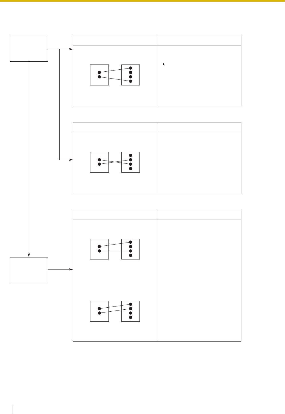
6.1.2 Connection
No
No
Can you dial
an extension?
Can you dial
out on a trunk?
Yes
Connection between the PBX and an SLT:
SOLUTIONCAUSE
The T/R is connected to the D1/D2. Use the correct cord (the inner 2 wires
are for T/R).
If a telephone equipped with an A-A1
relay is connected to the PBX, set
the A-A1 relay switch of the telephone
to "OFF".
PBX
T
R
T
R
Extension
Connection between the PBX and an SLT that is polarity-sensitive:
SOLUTIONCAUSE
The "T" is connected to the "R". Reverse the connections of the T/R.
PBX
T
R
T
R
Extension
Connection between the trunk and the PBX:
SOLUTIONCAUSE
Trunk is connected to the T2/T1. Reconnect the trunk to the T1/R1 or
T2/R2 of the telephone jack using
2-conductor wiring.
PBX
T
R
T
R
Extension
Trunk is connected to the T2/R1.
PBX
T
R
T
R
Extension
6.1.3 Operation
Note
For devices connected to a PBX other than the Main Unit, refer to the Troubleshooting for that PBX.
6.1.2 Connection
100

PROBLEM PROBABLE CAUSE SOLUTION
•Cannot set the IP
address, subnet mask
address, and PBX IP
address to the SIP
Phone.
•An unusable value is
being set.
•Set an IP address within the valid range.
IP address of the SIP Phone/PBX:
"1.0.0.0" to 223.255.255.255 Subnet mask
address: 0–255.0–255.0–255.0–255
(except 0.0.0.0 and "255.255.255.255")
•Cannot register the SIP
Phone.
•The necessary
network parameters
are not set to the SIP
Phone.
•When not using the DHCP Server feature
or an external DHCP server, set the IP
address, subnet mask address, and enter
the PBX IP address. If necessary, also
enter the IP address of the default
gateway.
•When using the DHCP Server feature or
an external DHCP server, enter the PBX
IP address.
•The SIP Phone cannot
connect to the PBX.
•The wrong IP
address, subnet
mask address, PBX
IP address, or default
gateway address
was entered.
•Check each parameter and enter the
correct value.
•The Ethernet cable is
not connected
correctly.
•Check the Ethernet cable connections.
•The DHCP server is
not active.
•Restart the external DHCP server.
•Confirm whether the DHCP Server feature
is enabled.
•Disable DHCP and re-enter settings as
appropriate.
•Whenever you try to
make calls using a SIP
phone, a busy tone is
heard.
•The status of the port
that the SIP phone is
connected to is Out
of Service.
•Change the port status from Out of Service
to In Service using Web Maintenance
Console.
•The SIP Phone does
not ring.
•The ringer volume is
off.
•Turn on the ringer volume.
The status of the port
property of an SLT
extension is FAULT.
•The telephone is off-
hook.
Put the telephone on-hook and restart the
PBX.
•There is a problem in
the wiring.
Disconnect all cabling between the PBX and
SLTs, and restart the PBX.
After restarting, if operation is normal, there is
probably a problem in the wiring or
connection. (For example, there might be a
short circuit in the switchboard or cabling.)
•The SLT circuitry is
damaged.
Consult a certified dealer.
6.1.3 Operation
101

6.1.4 Restarting the PBX
If the PBX does not operate properly, restart the PBX using Web Maintenance Console. Before restarting
the PBX, try the system feature again to confirm whether there definitely is a problem or not.
Note
•Restarting the PBX causes the following:
–Camp-on is cleared.
–Calls on hold are terminated.
–Calls on exclusive hold are terminated.
–Calls in progress are terminated.
–Call park is cleared.
Other data stored in memory, except the above, are not cleared.
Operation
For details about DHCP server setting, refer to "Maintenance-[4-2]System Reset-◆System Reset" in the
Programming Item List.
6.1.4 Restarting the PBX
102

Section 7
Appendix
This section provides information about System Prompt
Languages and the revision history.
103

7.1 System Prompt Languages
Note
•The following abbreviations are used in the language file names:
–UK: United Kingdom
–US: United States
–LA: Latin America
–CA: Canada
–BR: Brazil
•No. 1 is set by default. For details, see "PBX Configuration-[1-6]System Options- ◆Prompt Language" in
the Programming Item List.
System prompt languages stored in the System Memory
KX-HTS
Series
Suffix
AG AL BR HK US ML
No.1
(Primary)
LA-Spanish UK-English BR-
Portuguese
US-English US-English US-English
No.2 US-English US-English Mandarin LA-Spanish Mandarin
No.3 Taiwan
Mandarin
Taiwan
Mandarin
No.4 Cantonese Cantonese
No.5
No.1 (Primary) NZ RU SA BX
No.1
(Primary)
UK-English Russian UK-English US-English
No.2 Ukrainian LA-Spanish
No.3 US-English
No.4
No.5
7.1 System Prompt Languages
104

TEMPLATE FOR WALL MOUNTING
1. Copy or print this template and place it on the
wall.
2. Install the screws as marked. If you mount the
main unit on a concrete, fit anchor plugs(not
included) into the wall beforehand.
3. Hook the unit onto the screw heads.
Note
•Make sure to set the print size to
correspond with the size of this page.
•If the dimensions of the paper output still
deviate slightly from the measurements
indicated here, use the measurements
indicated here.
A 225mm (8-7 / 8 in)
(1) Install a screw here.
(1)
A
(1)
7.1 System Prompt Languages
105

0197 The KX-HTS32NE is designed to interwork with the:
•Analogue Public Switched Telephone Network (PSTN) of Europe-
an countries
Panasonic System Networks Co., Ltd. declares that the KX-HTS32NE is in compliance with the
essential requirements and other relevant provisions of Radio & Telecommunications Terminal
Equipment (R&TTE)
Directive 1999/5/EC. Declarations of Conformity for the relevant Panasonic products described in this
manual are available for download by visiting:
http://www.ptc.panasonic.eu

For Future Reference
Please print, record, and retain the following information for future reference.
Note
The serial number of this product can be found on the label affixed to the unit. You should record the
model number and the serial number of this unit as a permanent record of your purchase to aid in
identification in the event of theft.
Panasonic System Networks Co., Ltd.
1-62, 4-chome, Minoshima, Hakata-ku, Fukuoka 812-8531, Japan
Web Site: http://www.panasonic.net/
Copyright:
This material is copyrighted by Panasonic System Networks Co., Ltd., and may be reproduced for
internal use only. All other reproduction, in whole or in part, is prohibited without the written consent of
Panasonic System Networks Co., Ltd.
© Panasonic System Networks Co., Ltd. 2015
PNQX7549ZA PM0715HH0