Panasonic of North America 96NKX-NCP0158 1920 – 1930 MHz Digital Cordless Telephone System – Base Unit User Manual
Panasonic Corporation of North America 1920 – 1930 MHz Digital Cordless Telephone System – Base Unit
UserManual.wiki
>
Panasonic of North America
>
96NKX NCP0158 User Manual
user manual
Navigation menu
Upload a User Manual
Namespaces
Wiki Guide
HTML
PDF
Info
Views
User Manual
Discussion / Help
Navigation
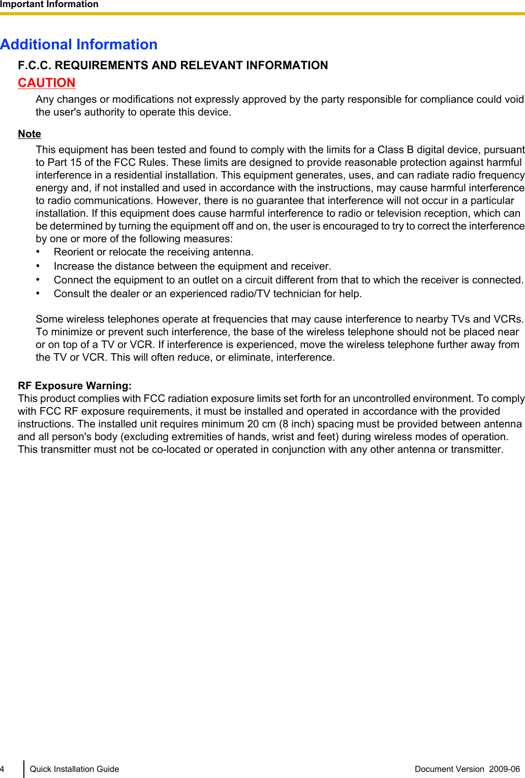
![Important InformationSAVE THESE INSTRUCTIONSSafety NoticesPlease observe the safety notices in this manual in order to avoid danger to users or other people, and preventdamage to property.The notices are classified as follows, according to the severity of injury or damage:WARNING This notice means that misuse could result in death or serious injury.CAUTION This notice means that misuse could result in injury or damage toproperty.WARNINGSAFETY REQUIREMENTS•Make sure that the wall that the unit will be attached to is strong enough to support the unit (approx.440 g [16 oz]). If not, it is necessary for the wall to be reinforced.•Only use the wall-mounting equipment (screws, washers, wall mounting plate) included with the unit.•When this unit is no longer in use, make sure to detach it from the wall.•Do not connect or disconnect the AC plug with wet hands.•Disconnect the unit from the AC outlet, disconnect the LAN cable, and contact the dealer if:–The AC adaptor cord, AC cord, AC plug, or DC extension cable (PQJA10200) becomes damagedor frayed.–The unit is exposed to rain, water, or any other liquid.–The unit is dropped or damaged.–Internal components are exposed due to damage.–The unit does not operate properly.–Performance deteriorates.•Disconnect the unit from the AC adaptor/DC extension cable (PQJA10200), and LAN cable if the unitemits smoke, an abnormal smell, or makes unusual noise. These conditions can cause fire or electricshock. Confirm that smoke has stopped and contact an authorized service centre.•Clean the AC plug periodically with a soft, dry cloth to remove dust and other debris.•Do not touch the unit, AC adaptor, AC adaptor cord, AC cord, or DC extension cable (PQJA10200)during a lightning storm.•If using an AC adaptor, use only the optional AC adaptor KX-A421 (PSLP1662).•Do not allow anything to rest on the AC adaptor cord, AC cord, DC extension cable (PQJA10200), orLAN cable. Do not locate this unit where the AC adaptor cord, AC cord, DC extension cable(PQJA10200), or LAN cable may be stepped on or tripped on.CAUTIONSAFETY REQUIREMENTS•The CS should be kept free of dust, moisture, high temperature (more than 40 °C [104 °F]), lowtemperature (less than 0 °C [32 °F]), and vibration, and should not be exposed to direct sunlight.•The CS should not be placed outdoors (use indoors).•The CS should not be placed near high-voltage equipment.•The CS should not be placed on a metal object.•The DC jack cover poses a choking hazard. Keep the DC jack cover out of reach of children.2 Quick Installation Guide Document Version 2009-06 Important Information](https://usermanual.wiki/Panasonic-of-North-America/96NKX-NCP0158/User-Guide-1130513-Page-2.png)
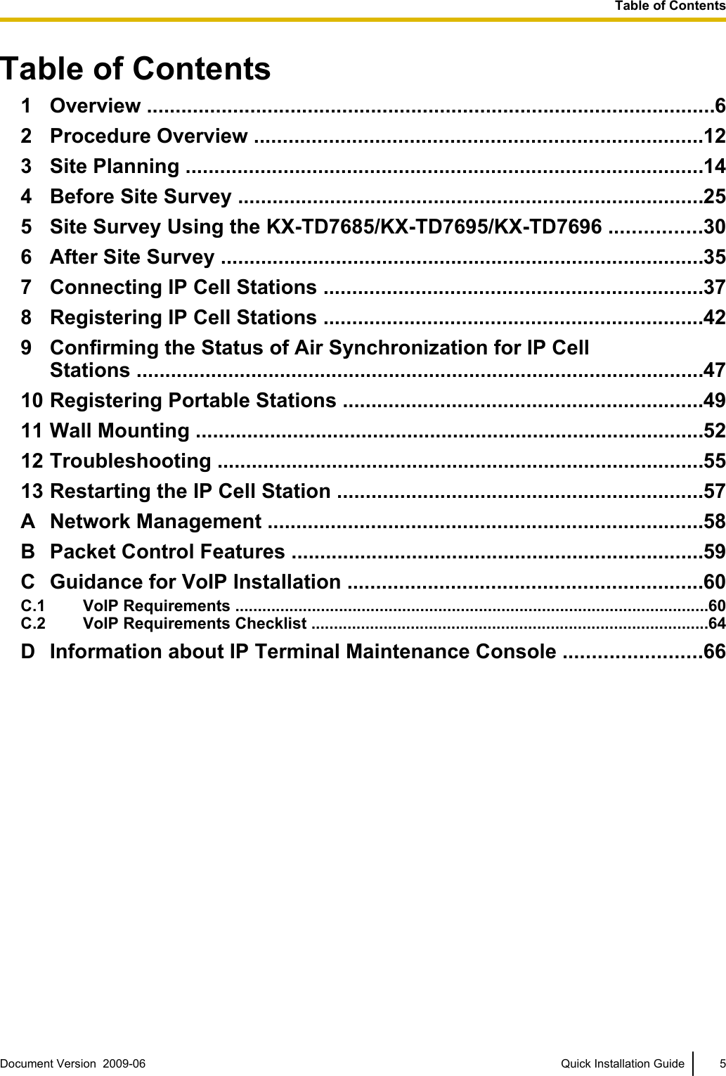
![Names and LocationsLEDAntennasCS ID Number(ID: xxxxxxxxxx)DIP SwitchRJ45 Modular DC JackUnpackingUnpack the box and check the items below:Cell Station 1Wall Mounting Plate 1Screws 2Washers 2LED IndicationsIndication Color DescriptionSTATUS Green/Red/AmberCS status indication•OFF: Power Off/CS Software downloading•Green ON: Stand-by (no active calls)•Slow Green Flashing: Talk (active calls)•Moderate Green Flashing: Busy*1•Red ON: Fault•Slow Red Flashing: Out of Service/Starting up (data linkestablishment ® air synchronization)•Moderate Red Flashing: Starting up (power on ® data linkestablishment)•Amber ON: Stand-by (unstable synchronization [no active calls])•Slow Amber Flashing: Talk (unstable synchronization [active calls])•Moderate Amber Flashing: Busy*1 (unstable synchronization)CS status indication during the site survey•Red ON: The CS is connected to an AC adaptor/PoE device.•Red Flashing (60 times per minute): The CS is connected to thePBX.CS status indication while restarting the CS•Red Flashing (120 times per minute): The CS is restarting.*1 All 8 channels are occupied.Document Version 2009-06 Quick Installation Guide 91 Overview](https://usermanual.wiki/Panasonic-of-North-America/96NKX-NCP0158/User-Guide-1130513-Page-9.png)
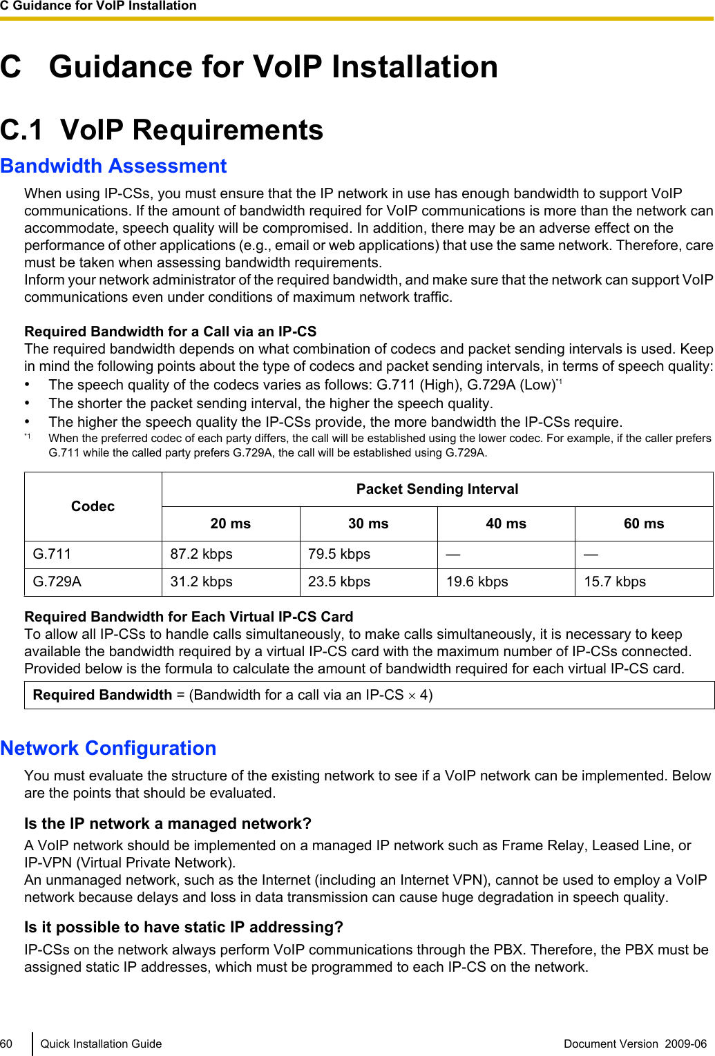
![RF SpecificationItem DescriptionRadio Access Method MultiCarrier TDMA-TDDFrequency Band 1920 MHz to 1930 MHzNumber of Carriers 5Carrier Spacing 1728 kHzBit Rate 1152 kbpsCarrier Multiplex TDMA, 24 (Tx12, Rx12) slots per frameFrame Length 10 msModulation Scheme GFSKRoll-off factor=0.5 50 % roll-off in the transmitterData Coding for Modulator Differential CodingVoice Codec 32 kbps ADPCM (CCITT G.726)CAUTION•The CS should be kept free of dust, moisture, high temperature (more than 40 °C [104 °F]), lowtemperature (less than 0 °C [32 °F]), and vibration, and should not be exposed to direct sunlight.•The CS should not be placed outdoors (use indoors).•The CS should not be placed near high-voltage equipment.•The CS should not be placed on a metal object.Document Version 2009-06 Quick Installation Guide 111 Overview](https://usermanual.wiki/Panasonic-of-North-America/96NKX-NCP0158/User-Guide-1130513-Page-11.png)
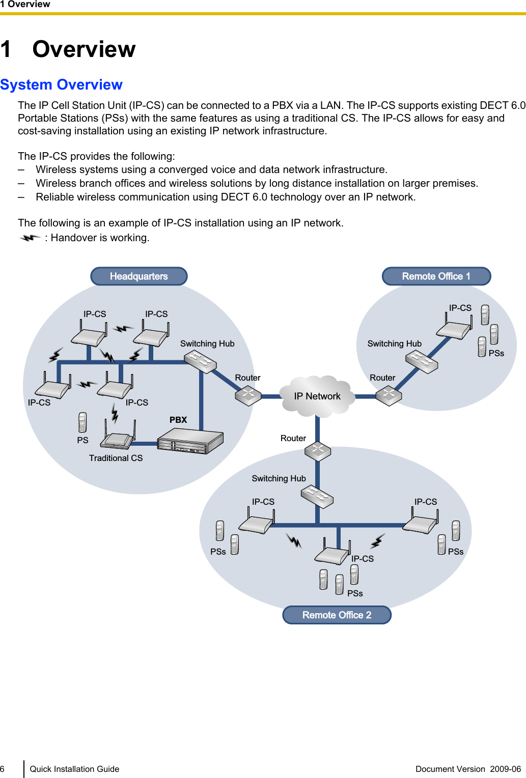
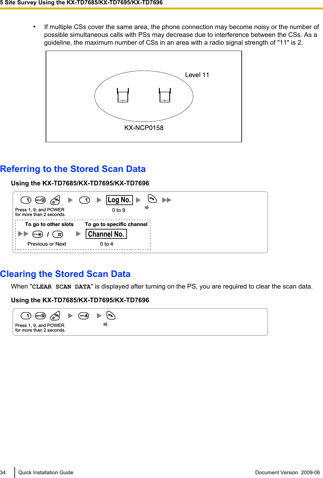
![CS Coverage Area for Establishing Conversation Using PSsThe example below shows the size of the area where one CS can cover PSs, if it is installed in an area withno obstacles.NoteRadio signal strength levels are measured during the site survey (refer to "5 Site Survey Using theKX-TD7685/KX-TD7695/KX-TD7696").ABCABGray Zone:Conversation will be intermittent Out of Service:Cannot make/receive calls.Good Coverage AreaRadio signal strengthlevel is greater than "8".(About 30 m to 40 m [98 ft to 131 ft])Good sound qualitycan be maintained.Coverage AreaRadio signal strength level is greater than "3".(About 50 m to 60 m [164 ft to 197 ft])Radio Signal Strength LevelsBetterGoodMay receive noiseReceives noise easily or disconnectsOut of rangeLevel: 11 to 12Level: 08 to 10Level: 03 to 07Level: 01 to 02Level: 0016 Quick Installation Guide Document Version 2009-06 3 Site Planning](https://usermanual.wiki/Panasonic-of-North-America/96NKX-NCP0158/User-Guide-1130513-Page-16.png)
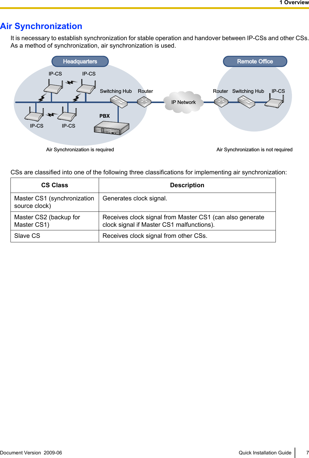
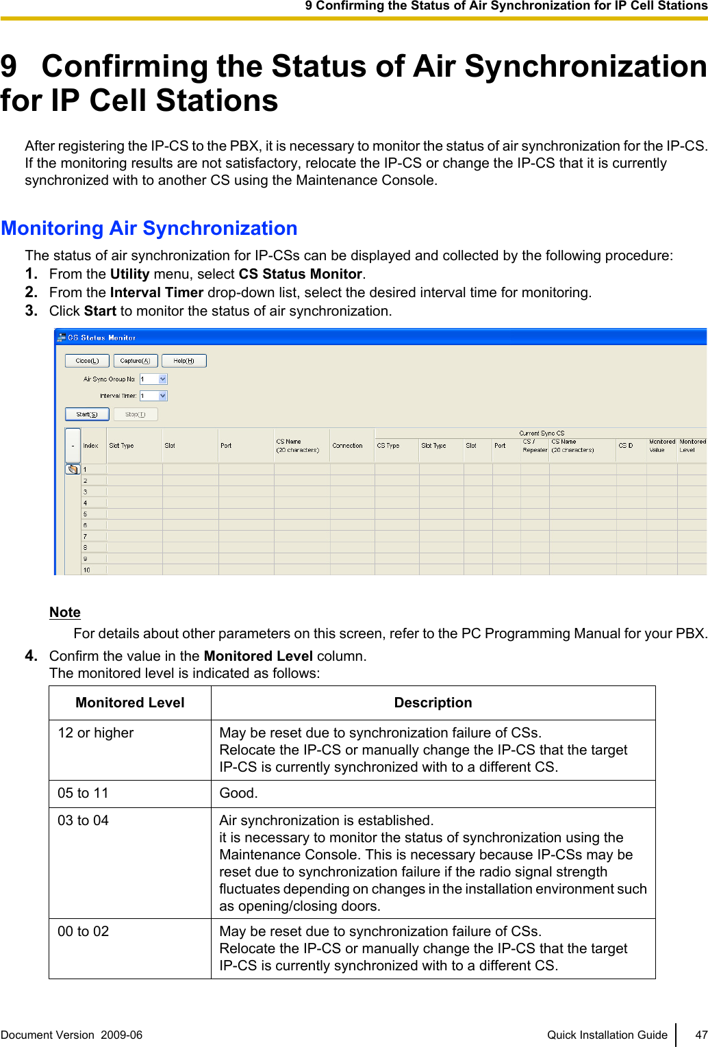
![Implementing Air SynchronizationCS Coverage Area for Air Synchronization between CSsThe example below shows the size of the area where one CS can synchronize with other CSs, if it is installedin an area with no obstacles.NoteRadio signal strength levels are measured during the site survey (refer to "5 Site Survey Using theKX-TD7685/KX-TD7695/KX-TD7696").ABCABGray Zone:Conversation will be intermittent Out of Service:Cannot be synchronized.Good Coverage AreaRadio signal strength level is between "5" (about 40 m to 50 m [131 ft to 164 ft]) and "11" (about 20 m to 30 m [65 ft to 98 ft]).Good synchronization qualitycan be maintained.Coverage AreaRadio signal strength level is greater than "3".(About 50 m to 60 m [164 ft to 197 ft])Radio Signal Strength LevelsLevel: 12 or higher May be reset due to synchronization failure of CSsLevel: 05 to 11 GoodLevel: 03 to 04 Air synchronization is established. However, it is necessary to monitor the status of synchronization using the Maintenance Console. This is necessary because IP-CSs may be reset due to synchronization failure if the radio signal strength fluctuates depending on changes in the installation environment such as opening/closing doors.Level: 00 to 02 May be reset due to synchronization failure of CSsDocument Version 2009-06 Quick Installation Guide 173 Site Planning](https://usermanual.wiki/Panasonic-of-North-America/96NKX-NCP0158/User-Guide-1130513-Page-17.png)
![Recommended ConfigurationTraditional CSIP-CS Primary CS Secondary CS[Configuration Example 1]DiagramSlave CS3Slave CS4Slave CS5Slave CS6Slave CS1Master CS1 Master CS2Slave CS2Air Synchronization TreeMaster CS1 Master CS2Slave CS1Slave CS2Slave CS4Slave CS3Slave CS5Slave CS6orororororororor: Hierarchy levels (e.g., Master CS2: 1st hierarchy level)20 Quick Installation Guide Document Version 2009-06 3 Site Planning](https://usermanual.wiki/Panasonic-of-North-America/96NKX-NCP0158/User-Guide-1130513-Page-20.png)
![[Configuration Example 2]DiagramMaster CS1(B)Slave CS5 Slave CS1 Slave CS4 Slave CS8Master CS1(A)Slave CS7 Slave CS3 Slave CS2 Slave CS6Air Synchronization TreeMaster CS1(A) Slave CS1Master CS1(B) Slave CS2Slave CS3Slave CS4Slave CS6Slave CS5Slave CS7Slave CS8orororororor: Hierarchy levels (e.g., Slave CS1: 1st hierarchy level)ororororororDocument Version 2009-06 Quick Installation Guide 213 Site Planning](https://usermanual.wiki/Panasonic-of-North-America/96NKX-NCP0158/User-Guide-1130513-Page-21.png)
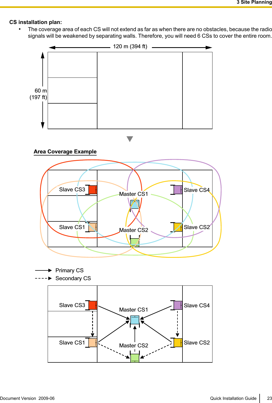
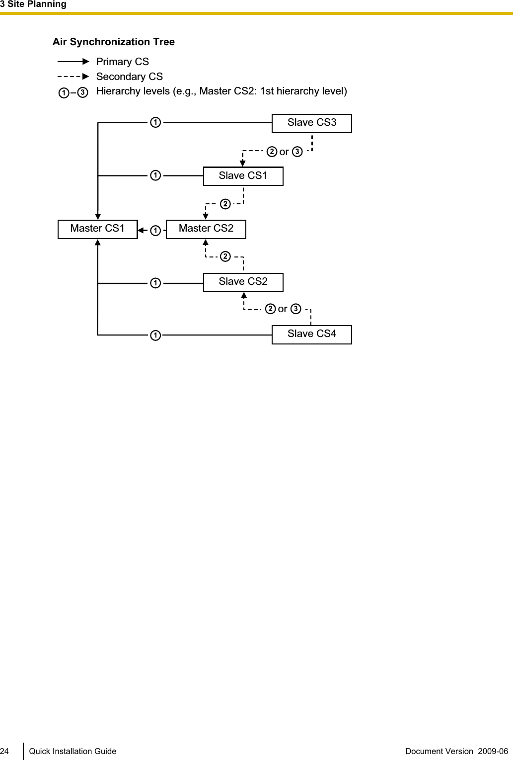
![Site Survey Preparation1. Obtain a map and investigate the installation site.a. Check the obstacles (e.g., shelves, columns, and partitions).b. Check the materials of the structures (e.g., metal, concrete, and plywood).c. Check the layout and dimensions of the room, corridor, etc.d. Write down the above information on the map.2. Examine the service area required by the user on the map.a. Draw the coverage area around a CS. Extend the coverage area 30 m to 60 m [98 ft to 197 ft] in eachdirection, depending on the materials of the building structures and obstacles in the installation site.Note that a CS cannot be installed outside a building.b. If one CS cannot cover the entire service area, install additional CSs as required. Overlap the coverageareas of adjacent CSs.Where CS coverage areas overlap, the PS will start call handover to the next CS if the signal from oneCS becomes weak. However, if a PS moves away from a CS and there are no CSs available forhandover, the PS may go out of range and the call could be lost.3. Keep a record of the air synchronization tree for reference.Example: Installing in a Room Separated by Interior WallsThings to take note of:•The room is separated by interior walls.•The room is surrounded by concrete walls.22 Quick Installation Guide Document Version 2009-06 3 Site Planning](https://usermanual.wiki/Panasonic-of-North-America/96NKX-NCP0158/User-Guide-1130513-Page-22.png)
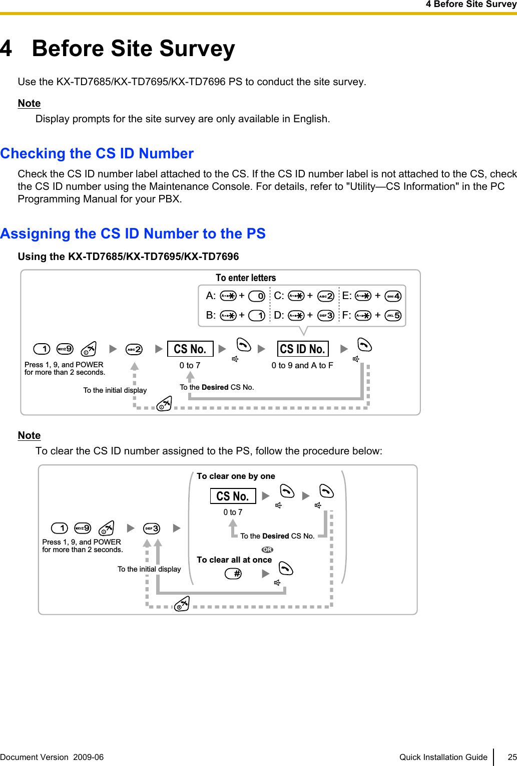
![Setting and Installing the CS Temporarily for Site Survey1. Switch the Radio Signal Test switch from OFF to ON.2. Set the channel number switches as desired.Channel Number SwitchChannel 1 Channel 2 Channel 3 Channel 41234123412341234DIP Switch12345678OFF ONRadio Signal Test SwitchChannel 01234Keep this switch at the default"OFF" position. Otherwise, theCS will not function.Initialized Mode Switch Fixed IP Setting Mode SwitchNoteIf more than one CS is in Radio Signal Test mode, each CS must have a unique channel number.3. After setting the DIP switches, connect the CS to an AC adaptor, battery, PoE hub, or PoE adaptor.[Connecting the AC Adaptor]WARNINGWhen installing or testing a product with an external AC adaptor, the AC adaptor should beplugged into a wall outlet or floor-mounted AC outlet. Do not connect the AC adaptor to aceiling-mounted AC outlet, as the weight of the adaptor may cause it to become disconnected.26 Quick Installation Guide Document Version 2009-06 4 Before Site Survey](https://usermanual.wiki/Panasonic-of-North-America/96NKX-NCP0158/User-Guide-1130513-Page-26.png)
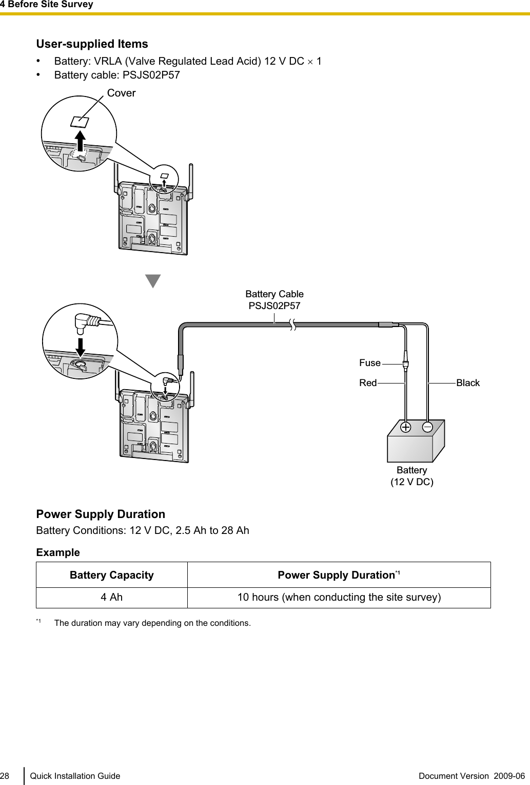
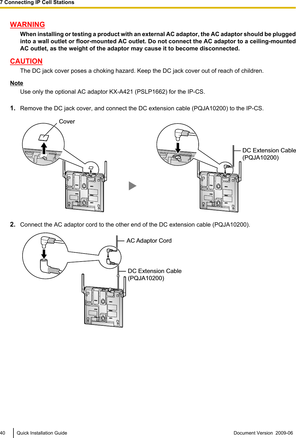
![CAUTIONThe DC jack cover poses a choking hazard. Keep the DC jack cover out of reach of children.To AC AdaptorKX-A421 (PSLP1662)Cover[Connecting the Battery]WARNING•Make sure that you do not short the battery or cables.•There is a danger of explosion if the battery is incorrectly replaced. Replace only with thesame or equivalent type recommended by the battery manufacturer. Dispose of the usedbattery according to the manufacturer's instructions.CAUTION•The DC jack cover poses a choking hazard. Keep the DC jack cover out of reach of children.•Use only the specified battery and battery cable (PSJS02P57) for the CS.•Make sure that the battery cable is securely fastened to both the battery and the CS.•Make sure that the polarities of the battery and wiring are correct.NoticeBe sure to comply with applicable local regulations (e.g., laws, guidelines).Note•The battery cable should not be exposed to direct sunlight. Keep the battery cable and the batteryaway from heating appliances and fire. Place the battery in a ventilated place.•For details about the battery, refer to the manual for the battery.Document Version 2009-06 Quick Installation Guide 274 Before Site Survey](https://usermanual.wiki/Panasonic-of-North-America/96NKX-NCP0158/User-Guide-1130513-Page-27.png)
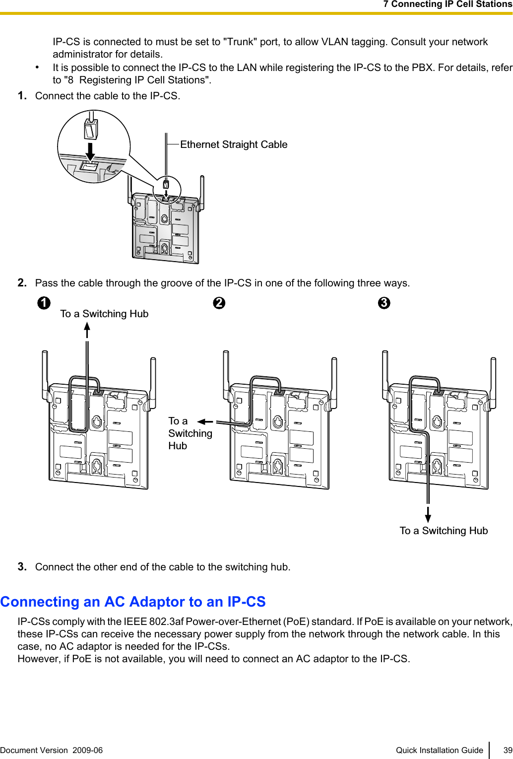
![[Connecting the PoE Hub or PoE Adaptor]Ethernet Straight CableTo PoE Hub/PoE Adaptor4. Install the CS temporarily for the site survey. Install the CS at least 2 m (6 ft 7 in) above the floor, and placethe antennas so that they are pointing in directions that are 90 degrees apart (for antenna diversity), asfollows:At least 2 m(6 ft 7 in)45º45º90ºDocument Version 2009-06 Quick Installation Guide 294 Before Site Survey](https://usermanual.wiki/Panasonic-of-North-America/96NKX-NCP0158/User-Guide-1130513-Page-29.png)
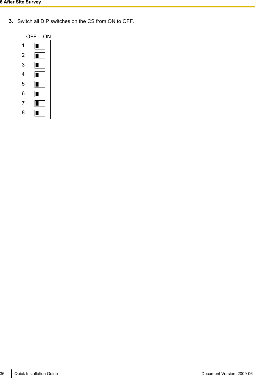
![6 After Site SurveyAfter obtaining the proper measurement results, exit Radio Signal Test mode by following the procedure below,before registering the CS to the PBX.1. Hold down the POWER button on the PS until the PS is off.2. Disconnect the CS from the AC adaptor, battery, PoE hub, or PoE adaptor to stop supplying electricity.[Disconnecting the AC Adaptor or Battery]NoticeBe sure to attach the cover to the DC jack after disconnecting the CS from the AC adaptor or battery.To AC AdaptorKX-A421 (PSLP1662)/BatteryCover[Disconnecting the PoE Hub or PoE Adaptor]Ethernet Straight CableTo PoE Hub/PoE AdaptorDocument Version 2009-06 Quick Installation Guide 356 After Site Survey](https://usermanual.wiki/Panasonic-of-North-America/96NKX-NCP0158/User-Guide-1130513-Page-35.png)
![10 Registering Portable StationsRegistering the PSThe PS must be registered to the PBX before it can be used. Programming of both the PS and PBX is required.A Proprietary Telephone (PT) with multiline display (e.g., KX-T7636 6-line display) is required to perform thePBX system programming.NoteFor details about system programming using a PT, refer to "PT Programming" in the Feature Guide,and "PT Programming" in the PT Programming Manual.Entering the PBX System Programming Mode Using a PTAdministrator Level#= 1234System Password for Administrator—for PT Programming Programming No.3 digitsPROGRAM/PAUSENote means default value.Setting the Personal Identification Number (PIN) for PS RegistrationTo prevent registering the PS to a wrong PBX, a PIN for PS registration can be set to the PBX. Before registeringthe PS to the PBX, enter the PIN set to the PBX into the PS. By doing so, the PS will only be registered to thePBX with the matching PIN.CAUTIONTo avoid unauthorized access and possible abuse of the PBX, we strongly recommend:a. Keeping the password (PIN for PS registration) secret.b. Not using the default password and changing the password regularly.c. Selecting a complex, random password that cannot be easily guessed.NoteThe PIN for PS registration will only be used when registering the PS to the PBX. Therefore, during normaloperation after registration, even if there is more than 1 PBX with the same PIN near the PS, the PS willnot be inadvertently linked to a different PBX.Setting the PIN for PBX[692]4 digitsPIN for PS RegistrationEND(HOLD)ENTER ENTER1234Document Version 2009-06 Quick Installation Guide 4910 Registering Portable Stations](https://usermanual.wiki/Panasonic-of-North-America/96NKX-NCP0158/User-Guide-1130513-Page-49.png)
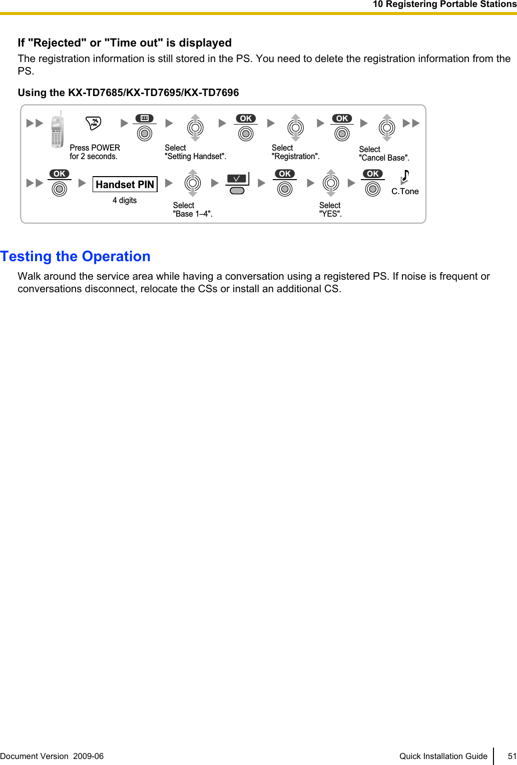
![Changing the Display Language of the PSUsing the KX-TD7685/KX-TD7695/KX-TD7696NoteThe illustrations shown in the procedure are based on the KX-TD7696 throughout this section.Select "Setting Handset".Select "Select Language".Select "Display Option".Select the desired language.Press POWERfor 2 seconds.PS RegistrationOne PS can be registered to a maximum of 4 different PBXs.[690]001 to max. no.of PSs (3 digits)PS No.1 to 5 digits END(HOLD)ENTER ENTERTo the PSoperationbelowExtn. No.Using the KX-TD7685/KX-TD7695/KX-TD7696Select "Setting Handset".Select "Register H/set".Select "Registration".Select "Base 1–4"."Please wait"."Enter Base PIN".Press POWERfor 2 seconds.C.Tone4 digitsPIN for PS RegistrationPS TerminationConfirm the following before cancelling the PS registration:•The PS is turned on.•The PS is within range.[691]001 to max. no.of PSs (3 digits)PS No.ENTER ENTEREND(HOLD)If "Rejected" or "Time out" is displayedCLEAR YESPress "YES".Press "CLEAR".50 Quick Installation Guide Document Version 2009-06 10 Registering Portable Stations](https://usermanual.wiki/Panasonic-of-North-America/96NKX-NCP0158/User-Guide-1130513-Page-50.png)
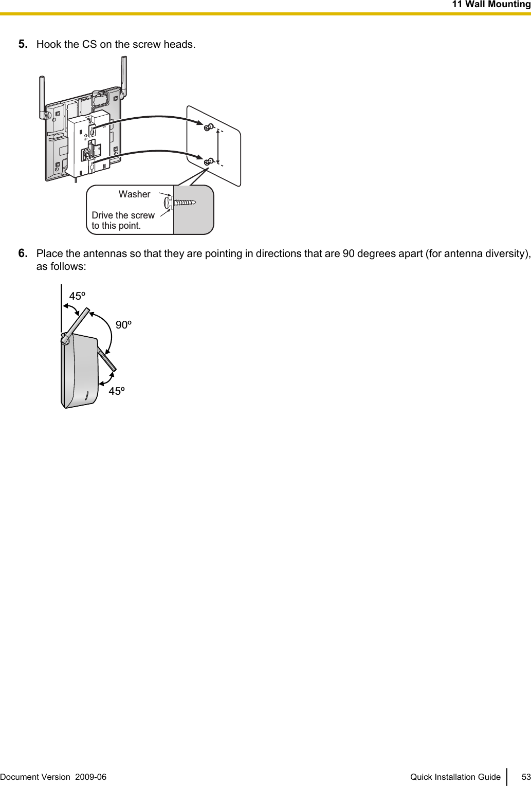
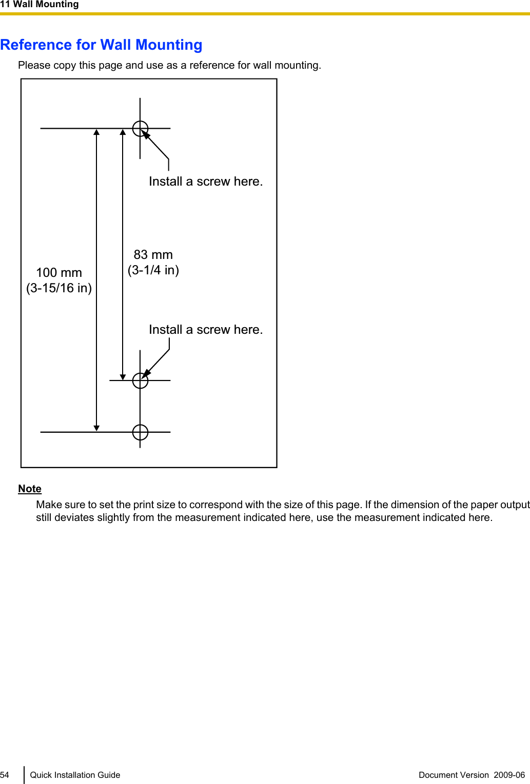
![11 Wall MountingMountingWARNING•Make sure that the wall that the unit will be attached to is strong enough to support the unit(approx. 440 g [16 oz]). If not, it is necessary for the wall to be reinforced.•Only use the wall-mounting equipment (screws, washers, wall mounting plate) included withthe unit.•When this unit is no longer in use, make sure to detach it from the wall.CAUTION•When driving the screws into the wall, be careful to avoid touching any metal laths, wire laths or metalplates in the wall.•Do not stretch or bend the cables. Also, do not allow anything to rest on the cables.•Use cables that are fire-resistant or fireproof.•The CS and the cables should never be placed near or over a radiator or other heat source.•Do not bundle cables that are connected to the CS with the AC power cords of machines locatednearby.•Make sure the cables are securely fastened to the wall.1. Place the reference for wall mounting on the wall to mark the 2 screw positions.2. Install the 2 screws and washers (included) into the wall.Note•Make sure that the screw heads are at the same distance from the wall.•Install the screws perpendicular to the wall.3. Insert the upper and lower tabs of the wall mounting plate into the designated openings in the base unit.TabsWall Mounting Plate (PSKL1032Y4)4. Slide the wall mounting plate in the direction of the arrow until it clicks.52 Quick Installation Guide Document Version 2009-06 11 Wall Mounting](https://usermanual.wiki/Panasonic-of-North-America/96NKX-NCP0158/User-Guide-1130513-Page-52.png)
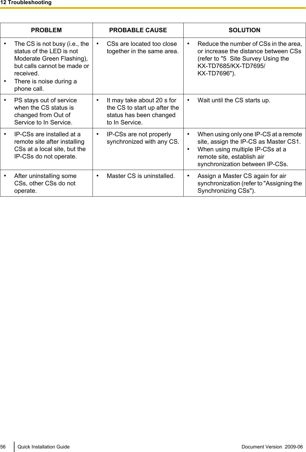
![12 TroubleshootingPROBLEM PROBABLE CAUSE SOLUTION•The LED of the CS does notchange to Green ON.•CS is not connectedproperly.•Make sure that the cable is connectedproperly with correct pin assignments.Also, make sure that the cable does notmake short circuits.•CS is not set for normaloperation.•Switch all DIP switches off.•The status of the port thatthe CS is connected to isOut of Service.•Change the port status from Out ofService to In Service using theMaintenance Console.•The LED of the CS staysRed ON during normaloperation.•CS malfunction •Replace the CS.•"CLEAR SCAN DATA" isdisplayed on the PS'sscreen after turning on thePS.•The PS cannot be used fornormal operation whenscan data is stored on thePS.•Clear the scan data by following theprocedure described in "Clearing theStored Scan Data" in this guide.•Cannot register the CSeven when maximumnumber of CSs is notexceeded.•The information oftraditional CSs that are notcurrently used is left on thesystem.•Change the Air SynchronizationGroup No. to None using theMaintenance Console (refer to "3.24[1-1] Slot—Port Property - ExtensionPort—DPT Type—Air Sync GroupNo" in the PC Programming Manual foryour PBX).•Cannot register the PS. •Wrong PersonalIdentification Number (PIN)is registered to the PS.•Enter the PIN set to the PBX into thePS.•PS becomes out of range.•Cannot make calls usingthe PS.•Location of CS is not good.•Access system of the PS isnot properly set.•Locate the CS properly (refer to "5 SiteSurvey Using the KX-TD7685/KX-TD7695/KX-TD7696").•Change the access system setting ofthe PS to the appropriate system orautomatic.•Noise is frequent whileusing the PS.•Conversations disconnectwhile using the PS.•"NO SERVICE" is displayedon the PS's screen.•Call handover is notworking.•PS is out of CS coveragearea.•Locate the CS properly (refer to "5 SiteSurvey Using the KX-TD7685/KX-TD7695/KX-TD7696").Document Version 2009-06 Quick Installation Guide 5512 Troubleshooting](https://usermanual.wiki/Panasonic-of-North-America/96NKX-NCP0158/User-Guide-1130513-Page-55.png)
![B Packet Control FeaturesJitter BufferWhen voice signals are packetized and transmitted, individual packets can take different paths through thenetwork and arrive at the destination at varied timings. This is referred to as "jitter", and it can cause degradationin speech quality. To compensate for jitter problems, the "jitter buffer" accumulates the packets temporarily forprocessing.To set the size of the jitter buffer, refer to "3.4 [1-1] Slot—Card Property - IPCMPR—VoIP-DSP Option" in thePC Programming Manual for your PBX.Voice Activity Detection (VAD)The VAD conserves bandwidth by detecting silent periods during a call and suppressing the packets of silencefrom being sent to the network. This feature can be enabled or disabled for codec G.711.To configure the VAD feature, refer to "3.21 [1-1] Slot—Port Property - Virtual IPCS—Voice Activity Detectionfor G.711" in the PC Programming Manual for your PBX.NoteTo use the VAD feature for a certain codec, be sure to enable it for that codec on both the local and remotegateway devices.Document Version 2009-06 Quick Installation Guide 59B Packet Control Features](https://usermanual.wiki/Panasonic-of-North-America/96NKX-NCP0158/User-Guide-1130513-Page-59.png)
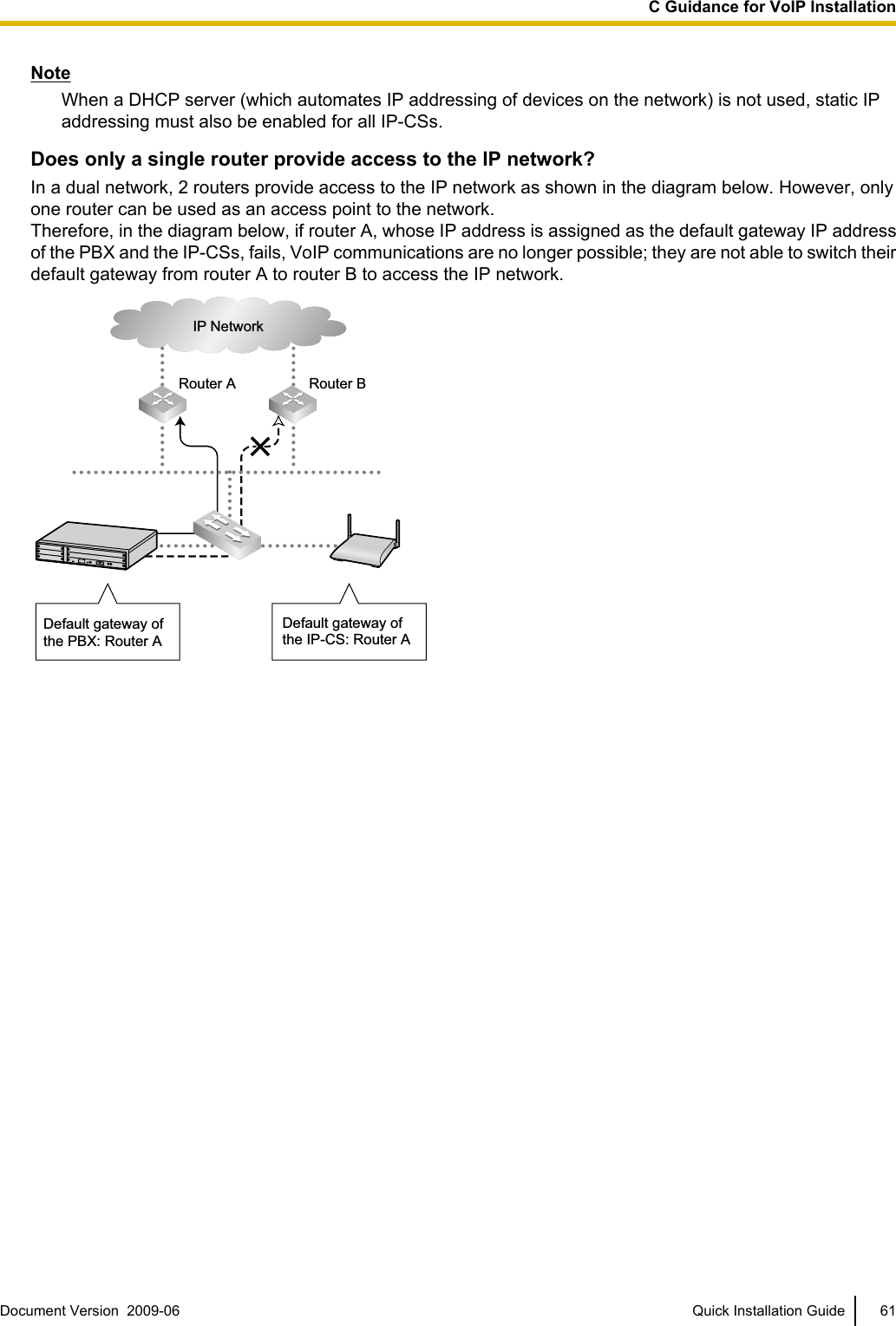
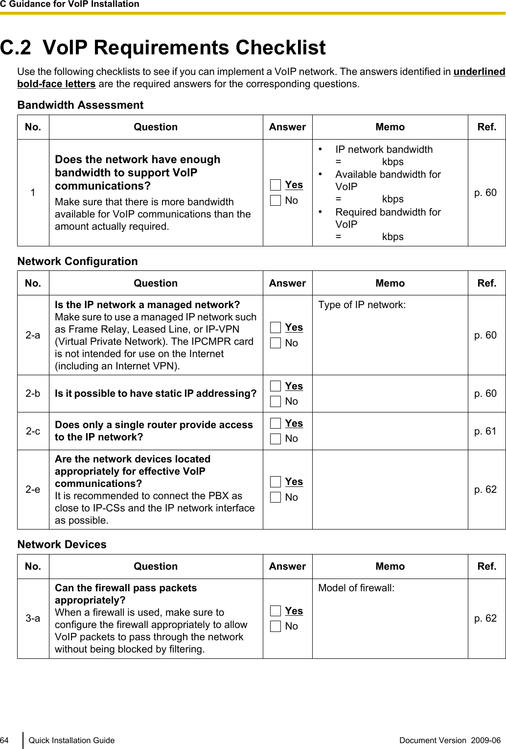
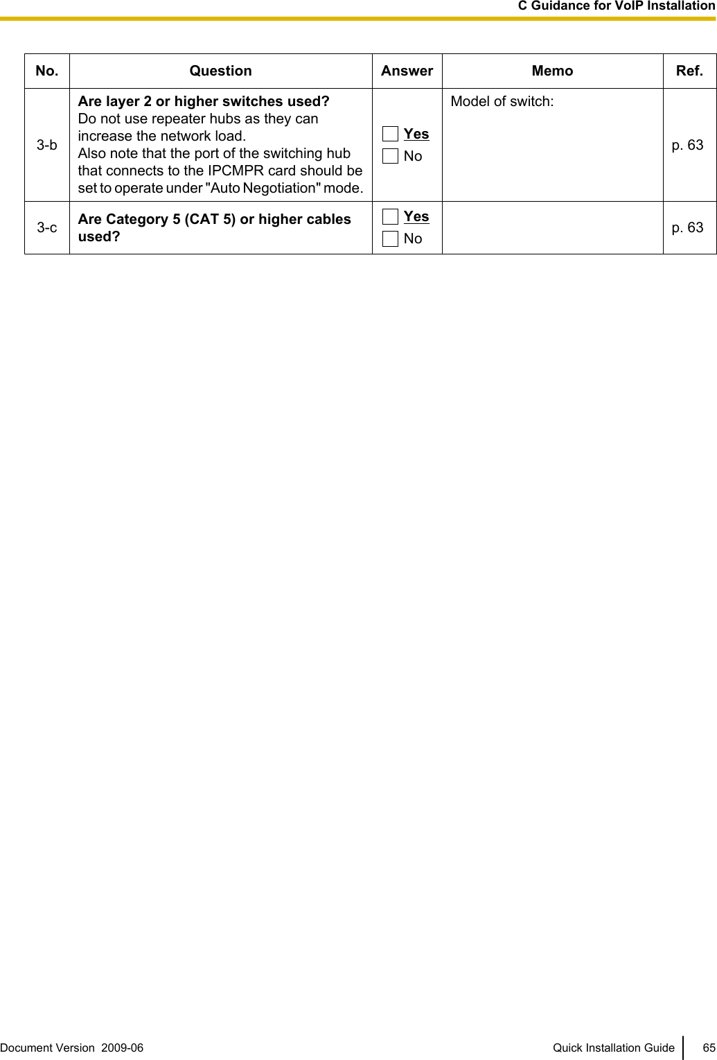
![Are the network devices located appropriately for effective VoIP communications?Transmission delays can cause pauses and loss in VoIP communications. The more network devices (e.g.,routers and switching hubs) there are between the PBX and IP-CSs or the IP network interface, the longer thetransmission delays. This is because a certain amount of delay is inevitable when packets go through eachnetwork device.To prevent unnecessary delays, it is recommended to connect the PBX as close to the IP-CSs and the IPnetwork interface as possible so that the number of the network devices is kept to a minimum.IP NetworkRouterRouterSwitching HubSwitching HubSwitching HubNetwork DevicesYou must evaluate the network devices that are used in the existing network to see if a VoIP network can beimplemented. Below are the points that should be evaluated.Can the firewall pass packets appropriately?If the VoIP network contains a firewall, the firewall must be configured appropriately to allow VoIP packets,listed in the table below, to pass through the network without being blocked by filtering.For more information, consult your network administrator.[IP Packets from IPCMPR Card and IP-CSs]Protocol Description TCP/UDP Default Port No.RTP (IP-CS) Real-time Transport Protocol.Used for voice data transmission.UDP 12000 to 12255Maintenance (IPCMPR) Panasonic proprietary protocol.Used for communication parameternegotiation with the PBX, download ofcountry/area data, confirmation ofconnection with the PBX, andnotification of error messages andstatistical information to the PBX.TCP 39300Maintenance (IP-CS) UDP 9301MGCP (IPCMPR) Media Gateway Control Protocol.Used for call control command data andLCD/LED data transmission.UDP 32727MGCP (IP-CS) UDP 2427DHCP (IPCMPR) Dynamic Host Configuration Protocol.Used for receiving an IP address from aDHCP server.UDP 67DHCP (IP-CS) UDP 68FTP (Port mode) File Transfer Protocol.Used for receiving a data file from a FTPserver to upgrade the firmware version.TCP 2162 Quick Installation Guide Document Version 2009-06 C Guidance for VoIP Installation](https://usermanual.wiki/Panasonic-of-North-America/96NKX-NCP0158/User-Guide-1130513-Page-62.png)