Panasonic of North America 96NKX-NS0154 DECT 6.0 Cordless Telephone Base Station for SIP server or PBX User Manual Quick Installation Guide English
Panasonic Corporation of North America DECT 6.0 Cordless Telephone Base Station for SIP server or PBX Quick Installation Guide English
Users Manual
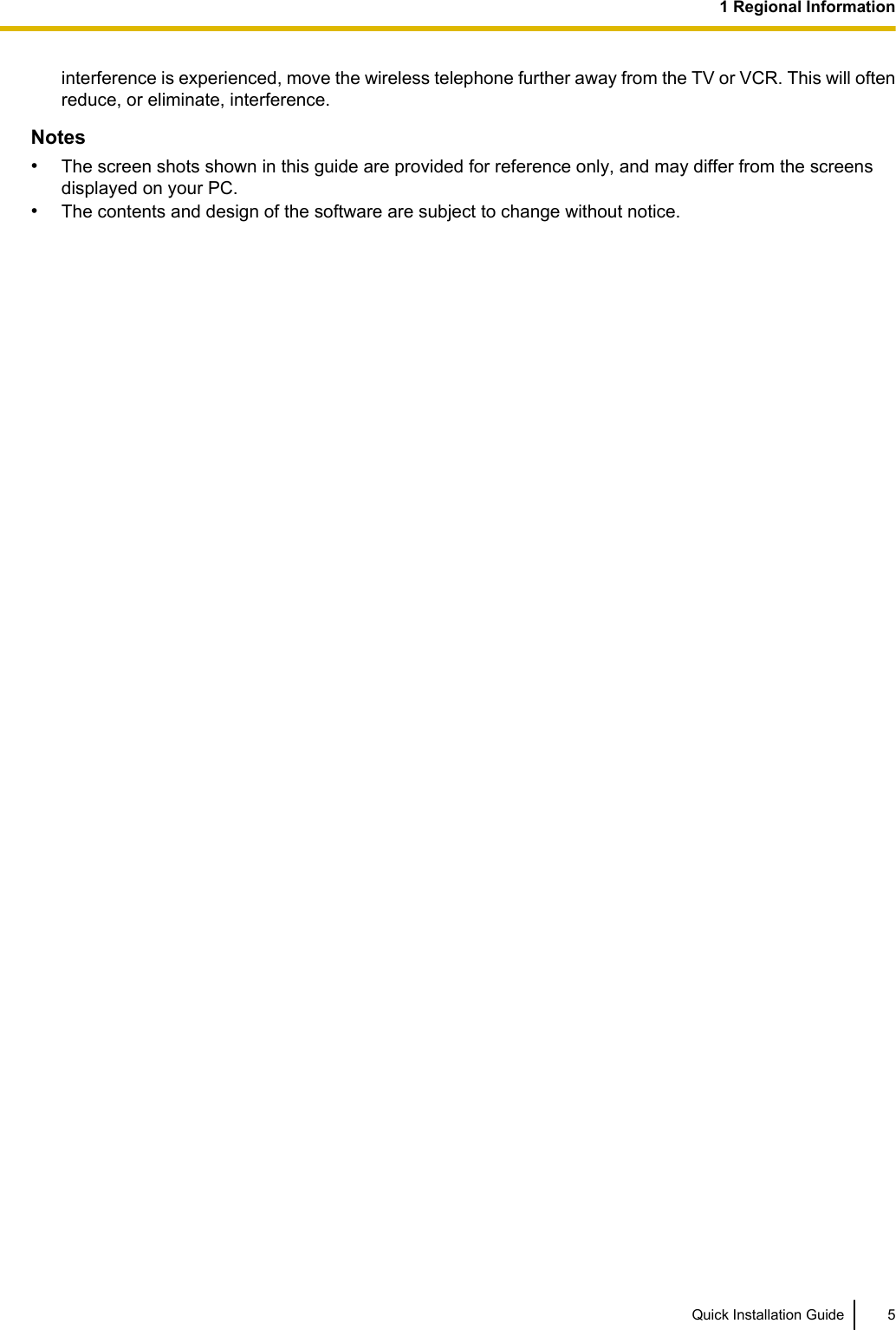
![Amber ON Stand-by (unstable synchronization [no active calls])Slow Flashing Talk (unstable synchronization [active calls])Moderate Flashing Busy*2 (unstable synchronization)*1 When the Activation Keys are applied, the Green color turns into Blue.*2 All channels are occupied.IP-CS status indication during the site surveyColor StatusRed ON The IP-CS is connected to the AC adaptor.Moderate Flashing The IP-CS is connected to a PoE device.IP-CS status indication while restarting the IP-CSColor StatusRed Moderate Flashing Moderate Red Flashing: The IP-CS is restarting.NoteLED flashing patterns are as follows:•Slow Flashing: 60 times per minute•Moderate Flashing: 120 times per minuteActivation KeysThe IP-CS supports the following activation keys to expand the maximum number of calls from 4ch to 8ch.Model No. Activation Key Type DescriptionKX-NSE201 1 IP-CS to 8 ch Allows the use of 1 IP-CS to 8 ch.KX-NSE205 5 IP-CSs to 8 ch Allows the use of 5 IP-CSs to 8 ch.KX-NSE210 10 IP-CSs to 8 ch Allows the use of 10 IP-CSs to 8 ch.KX-NSE220 20 IP-CSs to 8 ch Allows the use of 20 IP-CSs to 8 ch.Quick Installation Guide 93 Installing the IP-CSs](https://usermanual.wiki/Panasonic-of-North-America/96NKX-NS0154/User-Guide-2227896-Page-9.png)
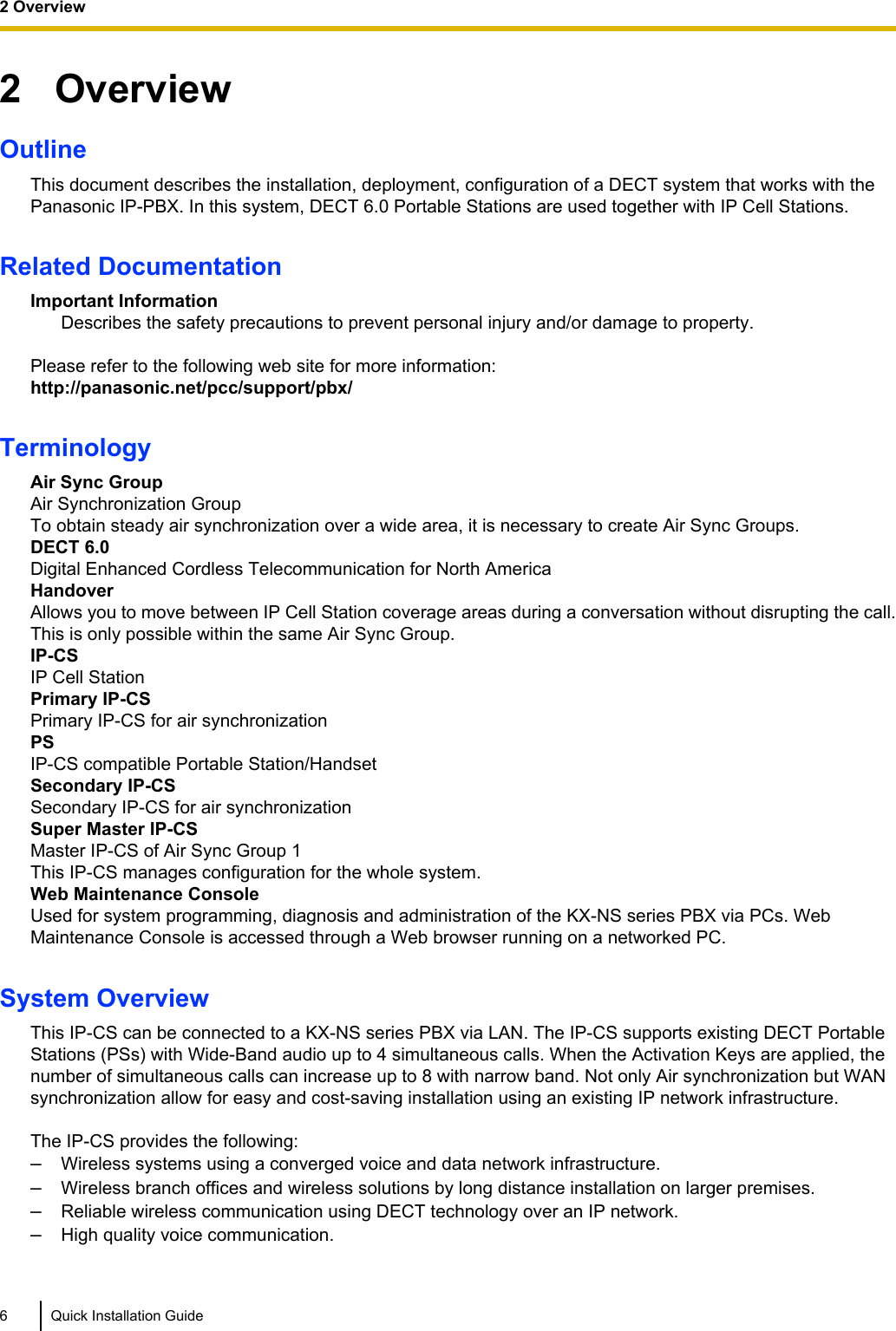
![6 Appendix6.1 SpecificationsIP-CS SpecificationType IP Cell Station UnitSupported Audio NarrowbandRadio Method DECT 6.0IP Port Number Flexible Setting YesLocal Setting Yes (through Web application)Site Survey Mode YesInitialization YesMaximum Simultaneous Calls 4, 8*1Power Supply PoE (IEEE 802.3af Class2)Optional AC adaptor (KX-A239 [PQLV206])VoIP Audio Codec G.711, G.729A, G.726LAN Port 10 BASE-T100 BASE-TXVLAN Yes (802.1Q)IP Addressing DHCPStatic IP Address SettingSoftware Upgrade YesBuilt-in VPN NoWeight 330 gSize (W) 190 mm ´ (H) 133.9 mm ´ (D) 39.3 mm*1 The activation keys are required to expand the maximum number of calls from 4ch to 8ch.For more details, refer to "Activation Keys".RF SpecificationItem DescriptionRadio Access Method MultiCarrier TDMA-TDDFrequency Band 1920 MHz to 1930 MHzNumber of Carriers 10Carrier Spacing 1728 kHz18 Quick Installation Guide6 Appendix](https://usermanual.wiki/Panasonic-of-North-America/96NKX-NS0154/User-Guide-2227896-Page-18.png)