Panasonic of North America 96NKX-NS0154 DECT 6.0 Cordless Telephone Base Station for SIP server or PBX User Manual Quick Installation Guide English
Panasonic Corporation of North America DECT 6.0 Cordless Telephone Base Station for SIP server or PBX Quick Installation Guide English
Users Manual
Quick Installation Guide
DECT 4-Channel IP Cell Station Unit
Model No. KX-NS0154
Thank you for purchasing this Panasonic product.
Please read this manual carefully before using this product and save this manual for future use.
Notes
•In this manual, the suffix of each model number (e.g., KX-NS0154CE) is omitted unless necessary.
•The screen shots shown in this guide are provided for reference only, and may differ from the screens displayed
on your PC.
•The contents and design of the software are subject to change without notice.
KX-NS0154: Software File Version 01.000 or later

Table of Contents
1 Regional Information ...............................................................................3
2 Overview ...................................................................................................6
3 Installing the IP-CSs ................................................................................8
3.1 Overview of IP-CSs ...........................................................................................................8
3.2 Connecting IP-CSs ..........................................................................................................10
3.3 Wall Mounting ..................................................................................................................12
3.4 Installing the Unified Maintenance Console .................................................................14
3.5 Initializing the IP-CS ........................................................................................................15
4 Deployment Procedure ..........................................................................16
4.1 Overview ..........................................................................................................................16
4.2 Site Planning ...................................................................................................................16
4.3 Site Survey .......................................................................................................................16
4.4 Example of How to Conduct the Site Survey ...............................................................16
4.5 Example of How to Make a Site Map .............................................................................16
4.6 Basic Network Configuration .........................................................................................16
4.7 CS Registration ...............................................................................................................16
4.8 Configuration and PS Registration (for a system using a KX-NS series) ..................16
5 Troubleshooting .....................................................................................17
6 Appendix .................................................................................................18
6.1 Specifications ..................................................................................................................18
2 Quick Installation Guide
Table of Contents
1 Regional Information
For users in the European Union only
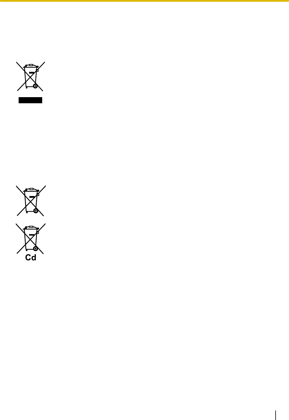
Information for Users on Collection and Disposal of Old Equipment and used Batteries
These symbols on the products, packaging, and/or accompanying documents mean that
used electrical and electronic products and batteries should not be mixed with general
household waste.
For proper treatment, recovery and recycling of old products and used batteries, please take
them to applicable collection points, in accordance with your national legislation and the
Directives 2002/96/EC and 2006/66/EC.
By disposing of these products and batteries correctly, you will help to save valuable
resources and prevent any potential negative effects on human health and the environment
which could otherwise arise from inappropriate waste handling.
For more information about collection and recycling of old products and batteries, please
contact your local municipality, your waste disposal service or the point of sale where you
purchased the items.
Penalties may be applicable for incorrect disposal of this waste, in accordance with national
legislation.
For business users in the European Union
If you wish to discard electrical and electronic equipment, please contact your dealer or
supplier for further information.
Information on Disposal in other Countries outside the European Union
These symbols are only valid in the European Union. If you wish to discard these items,
please contact your local authorities or dealer and ask for the correct method of disposal.
Note for the battery symbol (bottom two symbol examples):
This symbol might be used in combination with a chemical symbol. In this case it complies
with the requirement set by the Directive for the chemical involved.
Quick Installation Guide 3
1 Regional Information

Additional Information
F.C.C. AND INDUSTRY CANADA RELEVANT INFORMATION
CAUTION
Any changes or modifications not expressly approved by the party responsible for compliance could void
the user’s authority to operate this device.
Privacy of communications may not be ensured when using this unit.
Notice
FCC ID can be found on the back of this unit.
Note
This equipment has been tested and found to comply with the limits for a Class B digital device, pursuant
to Part 15 of the FCC Rules. These limits are designed to provide reasonable protection against harmful
interference in a residential installation. This equipment generates, uses, and can radiate radio frequency
energy and, if not installed and used in accordance with the instructions, may cause harmful interference
to radio communications. However, there is no guarantee that interference will not occur in a particular
installation. If this equipment does cause harmful interference to radio or television reception, which can
be determined by turning the equipment off and on, the user is encouraged to try to correct the interference
by one or more of the following measures:
•Reorient or relocate the receiving antenna.
•Increase the distance between the equipment and receiver.
•Connect the equipment to an outlet on a circuit different from that to which the receiver is connected.
•Consult the dealer or an experienced radio/TV technician for help.
This device complies with Part 15 of the FCC Rules. Operation is subject to the following two
conditions:
(1) this device may not cause harmful interference, and (2) this device must accept any interference
received, including interference that may cause undesired operation.
Some wireless telephones operate at frequencies that may cause interference to nearby TVs and VCRs.
To minimize or prevent such interference, the base of the wireless telephone should not be placed near
or on top of a TV or VCR. If interference is experienced, move the wireless telephone further away from
the TV or VCR. This will often reduce, or eliminate, interference.
RF Exposure Warning:
This product complies with FCC/IC radiation exposure limits set forth for an uncontrolled environment. To
comply with FCC/IC RF exposure requirements, this product must be installed and operated in accordance
with the provided instructions. The installed unit requires a minimum 20 cm (8 inches) of spacing between the
antenna and a person’s body during wireless modes of operation.
This transmitter must not be co-located or operated in conjunction with any other antennas or transmitters.
For Users in Canada Only
This Class B digital apparatus complies with Canadian ICES-003.
Note
Operation is subject to the following two conditions: (1) this device may not cause interference, and (2) this
device must accept any interference, including interference that may cause undesired operation of the
device.
Privacy of communications may not be ensured when using this telephone. Some wireless telephones
operate at frequencies that may cause interference to nearby TVs and VCRs. To minimize or prevent such
interference, the base of the wireless telephone should not be placed near, or on top of, a TV or VCR. If
4 Quick Installation Guide
1 Regional Information

interference is experienced, move the wireless telephone further away from the TV or VCR. This will often
reduce, or eliminate, interference.
Notes
•The screen shots shown in this guide are provided for reference only, and may differ from the screens
displayed on your PC.
•The contents and design of the software are subject to change without notice.
Quick Installation Guide 5
1 Regional Information

2 Overview
Outline
This document describes the installation, deployment, configuration of a DECT system that works with the
Panasonic IP-PBX. In this system, DECT 6.0 Portable Stations are used together with IP Cell Stations.
Related Documentation
Important Information
Describes the safety precautions to prevent personal injury and/or damage to property.
Please refer to the following web site for more information:
http://panasonic.net/pcc/support/pbx/
Terminology
Air Sync Group
Air Synchronization Group
To obtain steady air synchronization over a wide area, it is necessary to create Air Sync Groups.
DECT 6.0
Digital Enhanced Cordless Telecommunication for North America
Handover
Allows you to move between IP Cell Station coverage areas during a conversation without disrupting the call.
This is only possible within the same Air Sync Group.
IP-CS
IP Cell Station
Primary IP-CS
Primary IP-CS for air synchronization
PS
IP-CS compatible Portable Station/Handset
Secondary IP-CS
Secondary IP-CS for air synchronization
Super Master IP-CS
Master IP-CS of Air Sync Group 1
This IP-CS manages configuration for the whole system.
Web Maintenance Console
Used for system programming, diagnosis and administration of the KX-NS series PBX via PCs. Web
Maintenance Console is accessed through a Web browser running on a networked PC.
System Overview
This IP-CS can be connected to a KX-NS series PBX via LAN. The IP-CS supports existing DECT Portable
Stations (PSs) with Wide-Band audio up to 4 simultaneous calls. When the Activation Keys are applied, the
number of simultaneous calls can increase up to 8 with narrow band. Not only Air synchronization but WAN
synchronization allow for easy and cost-saving installation using an existing IP network infrastructure.
The IP-CS provides the following:
–Wireless systems using a converged voice and data network infrastructure.
–Wireless branch offices and wireless solutions by long distance installation on larger premises.
–Reliable wireless communication using DECT technology over an IP network.
–High quality voice communication.
6 Quick Installation Guide
2 Overview

–Easy maintenance using wireless download.
Activation Key Code and Key Management System
To obtain additional activation keys, you need to purchase the appropriate activation key codes and access
the Key Management System. You can download the activation keys as an activation key file from the Key
Management System.
To download the activation keys, enter the MPR ID number shown on the back of the main unit, and activation
key number and registration ID provided on each activation key code.
For information about the type of activation key codes available, refer to "Activation Keys".
Quick Installation Guide 7
2 Overview
3 Installing the IP-CSs
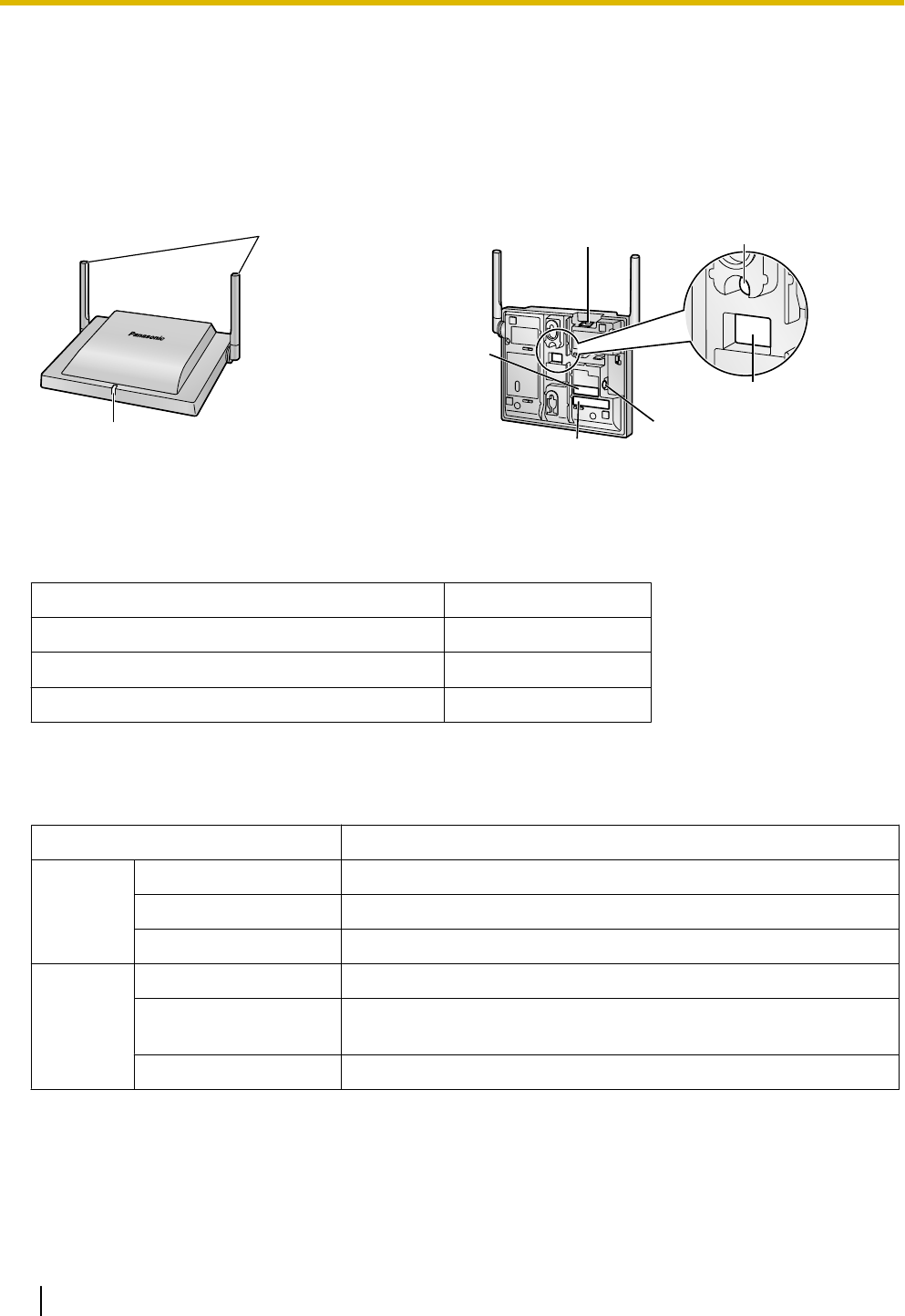
3.1 Overview of IP-CSs
Names and Locations
LED
Antennas
CS ID Number
(ID: xxxxxxxxxx)
DIP Switch
RESET Switch
DC Jack
MAC Address
RJ45 Modular
Unpacking
Unpack the box and check the items below:
IP-CS 1
Wall Mounting Plate 1
Screws 2
Washers 2
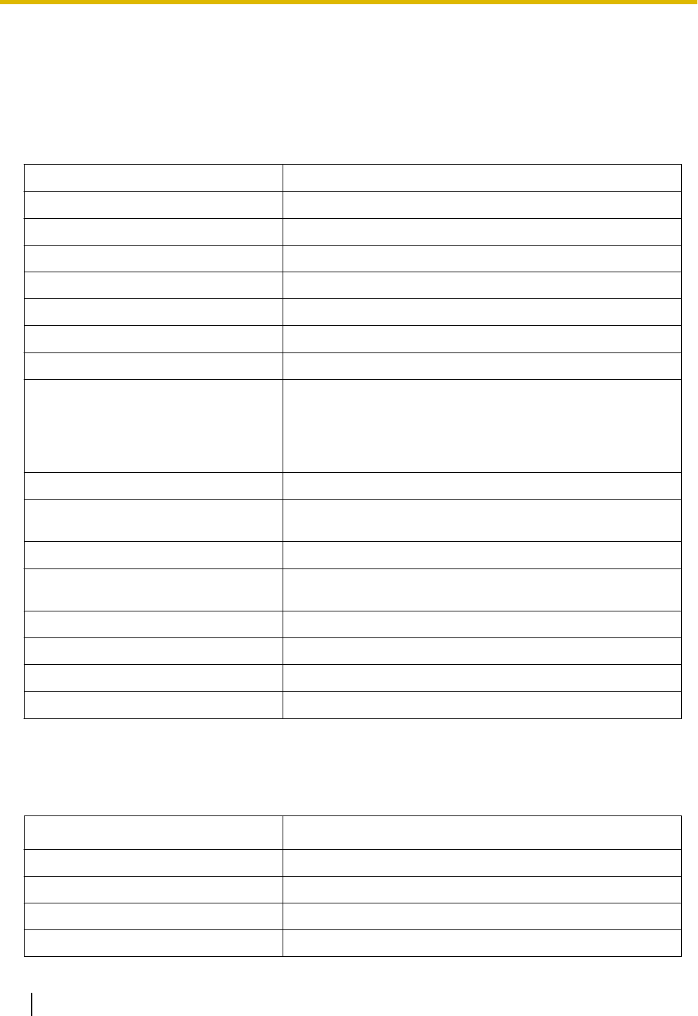
LED Indications
IP-CS status indication
Color Status
Green/
Blue*1
ON Stand-by (no active calls)
Slow Flashing Talk (active calls)
Moderate Flashing Busy*2
Red ON Fault
Slow Flashing Out of Service/Starting up (data link establishment ® air
synchronization)
Moderate Flashing (power on ® data link establishment)
8 Quick Installation Guide
3 Installing the IP-CSs
Amber ON Stand-by (unstable synchronization [no active calls])
Slow Flashing Talk (unstable synchronization [active calls])
Moderate Flashing Busy*2 (unstable synchronization)
*1 When the Activation Keys are applied, the Green color turns into Blue.
*2 All channels are occupied.
IP-CS status indication during the site survey
Color Status
Red ON The IP-CS is connected to the AC adaptor.
Moderate Flashing The IP-CS is connected to a PoE device.
IP-CS status indication while restarting the IP-CS
Color Status
Red Moderate Flashing Moderate Red Flashing: The IP-CS is restarting.
Note
LED flashing patterns are as follows:
•Slow Flashing: 60 times per minute
•Moderate Flashing: 120 times per minute
Activation Keys
The IP-CS supports the following activation keys to expand the maximum number of calls from 4ch to 8ch.
Model No. Activation Key Type Description
KX-NSE201 1 IP-CS to 8 ch Allows the use of 1 IP-CS to 8 ch.
KX-NSE205 5 IP-CSs to 8 ch Allows the use of 5 IP-CSs to 8 ch.
KX-NSE210 10 IP-CSs to 8 ch Allows the use of 10 IP-CSs to 8 ch.
KX-NSE220 20 IP-CSs to 8 ch Allows the use of 20 IP-CSs to 8 ch.
Quick Installation Guide 9
3 Installing the IP-CSs
3.2 Connecting IP-CSs
Connecting an IP-CS to a LAN
Notice
•Connect the units to the LAN only after completing network settings.
•When connecting a unit to the LAN, connect it to a switching hub.
Note
•Use an Ethernet straight cable with an RJ45 connector to connect the unit to a switching hub. The
cable should be a 10BASE-T/100BASE-TX CAT 5 (Category 5) or higher cable, and the diameter of
the cable must be 6.5 mm or less.
•It is possible to connect the unit to the LAN while registering the unit to the PBX.
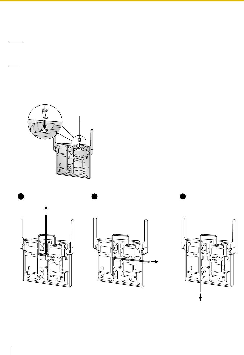
1. Connect the cable to the unit.
Ethernet Cable
2. Pass the cable through the groove of the unit in one of the following three ways.
To a Switching Hub
To a Switching Hub
12 31
To a
Switching
Hub
3. Connect the other end of the cable to the switching hub.
10 Quick Installation Guide
3 Installing the IP-CSs
Connecting an AC Adaptor to an IP-CS
The units comply with the IEEE 802.3af Power-over-Ethernet (PoE) standard. If PoE is available on your
network, these units can receive the necessary power supply from the network through the network cable. In
this case, no AC adaptor is needed for the units.
However, if PoE is not available, you will need to connect an AC adaptor to the unit.
WARNING
When installing or testing a unit with an external AC adaptor, the AC adaptor should be plugged
into a wall outlet or floor-mounted AC outlet. Do not connect the AC adaptor to a ceiling-mounted
AC outlet, as the weight of the adaptor may cause it to become disconnected.
Note
Use only the optional AC adaptor KX-A239 for the unit.
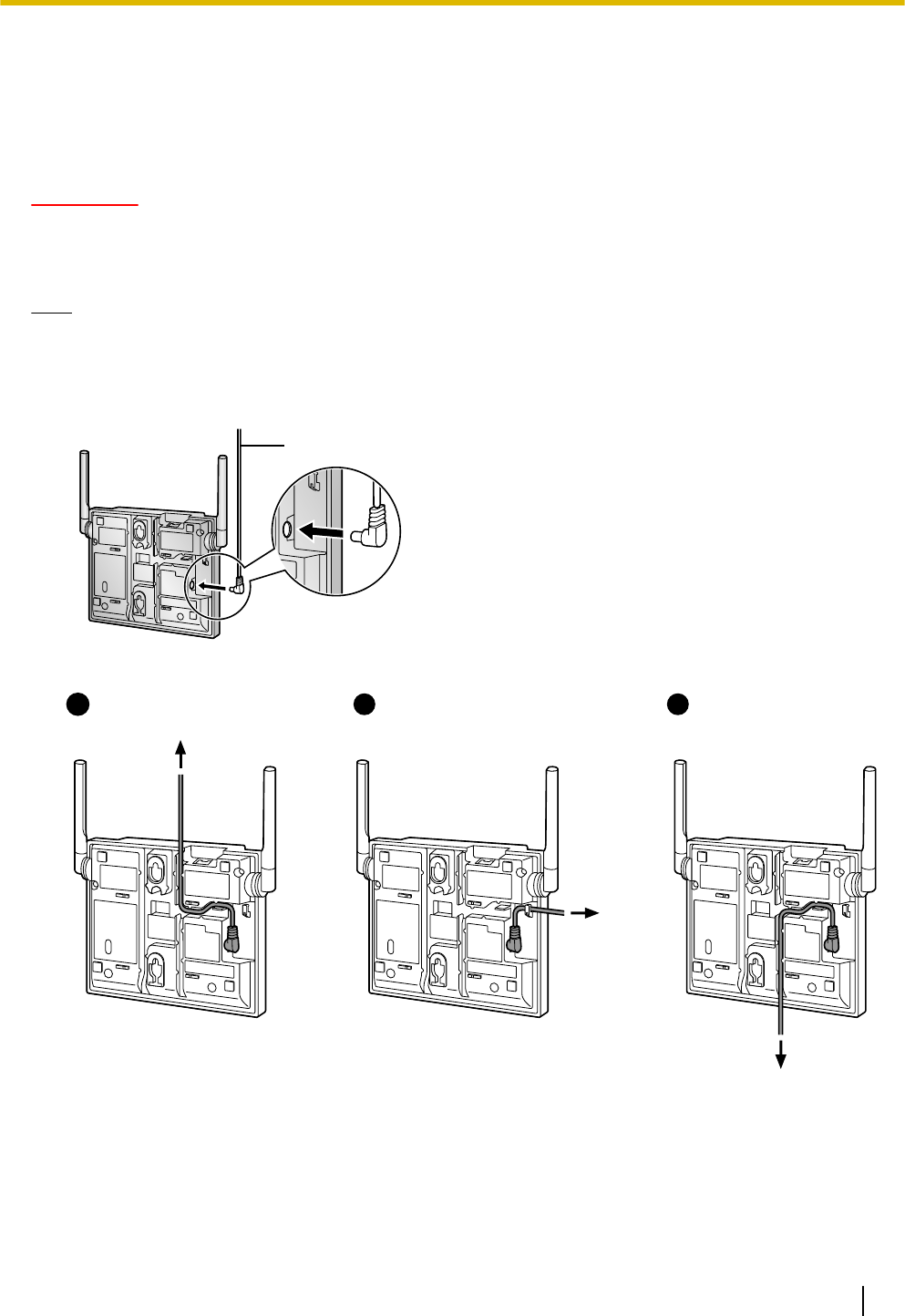
1. Connect the AC adaptor cord to the unit.
AC Adaptor Cord
2. Pass the cord through the groove of the unit in one of the following three ways.
To AC Adaptor
2
To AC Adaptor
3
To AC Adaptor
11
3. Connect the AC adaptor to an AC outlet.
Quick Installation Guide 11
3 Installing the IP-CSs

3.3 Wall Mounting
Mounting
WARNING
•Make sure that the wall that the unit will be attached to is strong enough to support the unit
(approx. 330 g). If not, it is necessary for the wall to be reinforced.
•Only use the wall-mounting equipment included with the unit.
•When the unit is no longer in use, make sure to detach it from the wall.
CAUTION
•When driving the screws into the wall, be careful to avoid touching any metal laths, wire laths or metal
plates in the wall.
•Do not stretch or bend the cables. Also, do not allow anything to rest on the cables.
•Use cables that are fire-resistant or fireproof.
•The unit and the cables should never be placed near or over a radiator or other heat source.
•Do not bundle cables that are connected to the unit with the AC power cords of machines located
nearby.
•Make sure the cables are securely fastened to the wall.
Notice
Panasonic assumes no responsibility for injuries or property damage resulting from failures arising out of
improper installation or operation inconsistent with this documentation.
1. Place the reference for wall mounting on the wall to mark the 2 screw positions.
2. Install the 2 screws and washers (included) into the wall.
Note
•Make sure that the screw heads are at the same distance from the wall.
•Install the screws perpendicular to the wall.
3. Insert the upper and lower tabs of the wall mounting plate into the designated openings in the unit.
4. Pass the AC adaptor cord and LAN cable through the hole of the wall mounting plate.
5. Slide the wall mounting plate in the direction of the arrow until it clicks.
6. Hook the unit on the screw heads.
12 Quick Installation Guide
3 Installing the IP-CSs
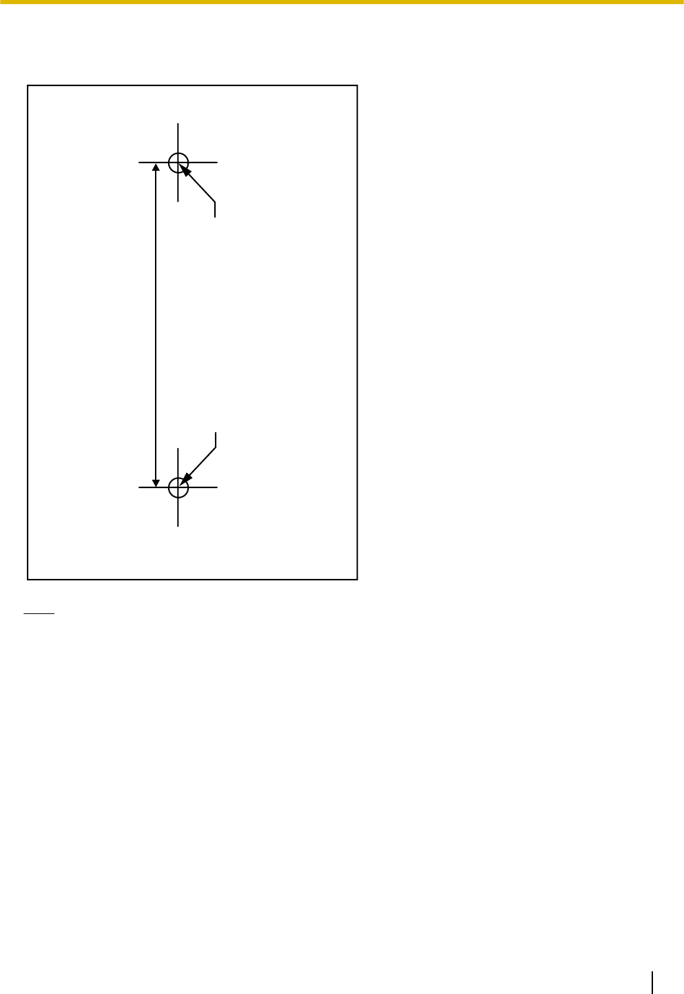
Reference for Wall Mounting
Please copy this page and use as a reference for wall mounting.
Install a screw here.
Install a screw here.
83 mm
Note
Make sure to set the print size to correspond with the size of this page. If the dimension of the paper output
still deviates slightly from the measurement indicated here, use the measurement indicated here.
Quick Installation Guide 13
3 Installing the IP-CSs

3.4 Installing the Unified Maintenance Console
System Requirements
Required Operating System
•Microsoft® Windows® XP, Windows Vista® Business, Windows 7, Windows 7 Professional, Windows 8 or
Windows 8 Professional operating system
Minimum Hardware Requirements
•HDD: 100 MB of available hard disk space
•The PC must fulfill the hardware requirements of the installed Microsoft Windows operating system.
Recommended Display Settings
•Screen resolution: XGA (1024 ´ 768)
•DPI setting: Normal size (96 DPI)
Installing the Maintenance Console
Note
•Make sure to install and use the latest version of the KX-TDA/KX-TDE/KX-NCP Unified Maintenance
Console.
•To install or uninstall the software on a PC running Windows XP Professional, you must be logged in
as a user in either the "Administrators" or "Power Users" group.
•To install or uninstall the software on a PC running Windows Vista Business or Windows 7 Professional,
you must be logged in as a user in the "Administrators" group.
1. Copy the setup file of the Unified Maintenance Console to your PC.
2. Double-click the setup file to run the installer.
3. Follow the on-screen instructions provided by the installation wizard.
14 Quick Installation Guide
3 Installing the IP-CSs
3.5 Initializing the IP-CS
If the IP-CS does not operate properly, initialize the IP-CS. Before initializing the IP-CS, try the system feature
again to confirm whether there definitely is a problem or not.
The settings that are configured by using the IP Terminal Maintenance Console are changed back to their
factory default by initializing the IP-CS.
While initializing the IP-CS, calls cannot be made or received and ongoing conversations will be disconnected.
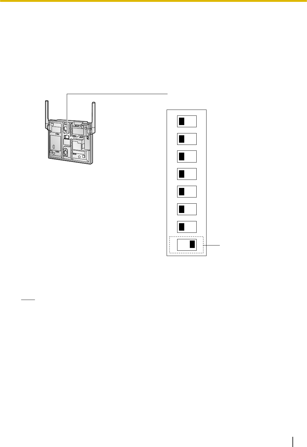
1. Switch the Initialized Mode switch from OFF to ON.
1
2
3
4
5
6
7
8
OFF ON
DIP Switch
Initialised Mode Switch
2. Supply electricity to the IP-CS using an AC adaptor, PoE hub, or PoE adaptor (turn on the IP-CS).
3. While the LED indicator flashes red (Moderate Flashing: 120 times per minute), switch the Initialized Mode
switch from ON to OFF.
Note
When the LED turns off for a while then flashes red, initialization is complete.
Quick Installation Guide 15
3 Installing the IP-CSs

4 Deployment Procedure
4.1 Overview
4.2 Site Planning
4.3 Site Survey
4.4 Example of How to Conduct the Site Survey
4.5 Example of How to Make a Site Map
4.6 Basic Network Configuration
4.7 CS Registration
4.8 Configuration and PS Registration (for a system
using a KX-NS series)
16 Quick Installation Guide
4 Deployment Procedure

5 Troubleshooting
Quick Installation Guide 17
5 Troubleshooting
6 Appendix
6.1 Specifications
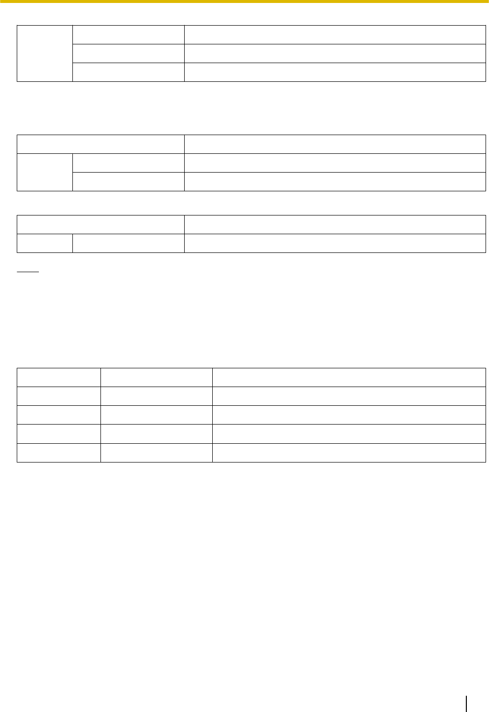
IP-CS Specification
Type IP Cell Station Unit
Supported Audio Narrowband
Radio Method DECT 6.0
IP Port Number Flexible Setting Yes
Local Setting Yes (through Web application)
Site Survey Mode Yes
Initialization Yes
Maximum Simultaneous Calls 4, 8*1
Power Supply PoE
(IEEE 802.3af Class2)
Optional AC adaptor
(KX-A239 [PQLV206])
VoIP Audio Codec G.711, G.729A, G.726
LAN Port 10 BASE-T
100 BASE-TX
VLAN Yes (802.1Q)
IP Addressing DHCP
Static IP Address Setting
Software Upgrade Yes
Built-in VPN No
Weight 330 g
Size (W) 190 mm ´ (H) 133.9 mm ´ (D) 39.3 mm
*1 The activation keys are required to expand the maximum number of calls from 4ch to 8ch.
For more details, refer to "Activation Keys".
RF Specification
Item Description
Radio Access Method MultiCarrier TDMA-TDD
Frequency Band 1920 MHz to 1930 MHz
Number of Carriers 10
Carrier Spacing 1728 kHz
18 Quick Installation Guide
6 Appendix
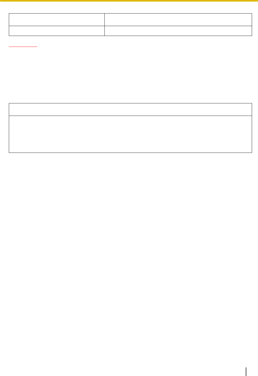
Item Description
Transmission Output Peak 250 mW
CAUTION
•The IP-CS should be kept free of dust, moisture, high temperature (more than 40 °C), low temperature
(less than 0 °C), and vibration, and should not be exposed to direct sunlight.
•The IP-CS should not be placed outdoors (use indoors).
•The IP-CS should not be placed near high-voltage equipment.
•The IP-CS should not be placed on a metal object.
Compatible PSs
Model No.
•KX-TCA185
•KX-TCA285
•KX-TCA385
•KX-WT125/KX-WT126
•KX-TD7685/KX-TD7695/KX-TD7969
Quick Installation Guide 19
6 Appendix

Panasonic System Networks Co., Ltd. declares that the unit is in compliance with the essential requirements and
other relevant provisions of Radio Telecommunications Terminal Equipment (RTTE) Directive 1999/5/EC.
Declarations of Conformity for the relevant Panasonic products described in this manual are available for download
by visiting:
http://www.ptc.panasonic.eu
Contact to Authorized Representative:
Panasonic Testing Center
Panasonic Marketing Europe GmbH
Winsbergring 15, 22525 Hamburg, Germany
1-62, 4-chome, Minoshima, Hakata-ku, Fukuoka 812-8531, Japan
Web Site: http://www.panasonic.net/
Copyright:
This material is copyrighted by Panasonic System Networks Co., Ltd., and may be reproduced for internal use
only. All other reproduction, in whole or in part, is prohibited without the written consent of Panasonic System
Networks Co., Ltd.
© Panasonic System Networks Co., Ltd. 2014
PNQX6649ZA PP0414TM0