Panasonic of North America 96NKX-UT248 SIP Phone User Manual
Panasonic Corporation of North America SIP Phone Users Manual
Users Manual

KX-UT113/KX-UT123
Model No. KX-UT133/KX-UT136/KX-UT248
<KX-UT136>
Document Version: 2011-10
SIP Phone
Thank you for purchasing this Panasonic product.
Please read this manual carefully before using this product and save this manual for future use.
KX-UT113/KX-UT123/KX-UT133/KX-UT136/KX-UT248: Software File Version 01.000 or later
In this manual, the suffix of each model number is omitted unless necessary.

Introduction
Feature Highlights
Easy Operation
You can easily access features using the Navigator key, fixed buttons, and soft buttons.
Also, the Message/Ringer lamp will inform you when you have an incoming call or a message waiting.
High-quality Voice Communication
This unit implements the standard SIP protocol, enabling high-quality voice communication.
ECO Mode
Enabling ECO mode allows you to use this unit while reducing the amount of electricity consumed.
Compatible with Electric Hook Switch (EHS) Headsets (KX-UT133/
KX-UT136/KX-UT248 only)
The KX-UT133/KX-UT136/KX-UT248 supports EHS headsets.
Compatible with Bluetooth® Wireless Headsets (KX-UT248 only)
The KX-UT248 supports Bluetooth wireless headsets.
2 Operating Instructions Document Version 2011-10
Introduction

Other Information
Outline
This manual describes information about the installation and operation of the unit.
Related Documentation
Getting Started
Briefly describes basic information about the installation of the unit.
Administrator Guide
Describes information about the programming and maintenance of the unit.
Manuals and supporting information are provided on the Panasonic Web site at:
http://www.panasonic.com/sip (for users in the United States)
http://panasonic.net/pcc/support/sipphone (for users in Canada)
Note
•The contents and design of the software are subject to change without notice.
Trademarks
•The Bluetooth® word mark and logos are owned by the Bluetooth SIG, Inc. and any use of such marks by
Panasonic Corporation is under license.
•Plantronics, Savi, and Voyager are trademarks or registered trademarks of Plantronics, Inc.
•All other trademarks identified herein are the property of their respective owners.
Document Version 2011-10 Operating Instructions 3
Introduction

When you ship the product (For users in the United States only)
Carefully pack and send it prepaid, adequately insured and preferably in the original carton. Attach a
postage-paid letter, detailing the symptom to the outside of the carton.
DO NOT send the product to the Executive or Regional Sales offices. They are NOT equipped to make repairs.
Product Service (For users in the United States only)
Panasonic factory service centers for this product are listed in the service center directory.
Consult your authorized Panasonic dealer for detailed instructions.
For Future Reference
Record the information in the space below for future reference.
Note
•The serial number and MAC address of this product may be found on the label affixed to the bottom
of the unit. You should note the serial number and MAC address of this unit in the space provided and
retain this manual as a permanent record of your purchase to aid in identification in the event of theft.
MODEL NO.
SERIAL NO.
DATE OF PURCHASE
NAME OF DEALER
DEALER'S ADDRESS
DEALER'S TEL. NO.
MAC ADDRESS
4 Operating Instructions Document Version 2011-10
Introduction
For Your Safety
To reduce the risk of injury, loss of life, electric shock,
fire, malfunction, and damage to equipment or property,
always observe the following safety precautions.
Explanation of symbols
The following symbols are used to classify and describe
the level of hazard and injury caused when the
denotation is disregarded and improper use is
performed.
WARNING
Denotes a potential hazard that could result in
serious injury or death.
CAUTION
Denotes a hazard that could result in minor injury or
damage to the unit or other equipment.
The following symbols are used to classify and describe
the type of instructions to be observed.
This symbol is used to alert users to a specific
operating procedure that must not be
performed.
This symbol is used to alert users to a specific
operating procedure that must be followed in
order to operate the unit safely.
WARNING
General Safety
Do not disassemble this unit. Dangerous
electrical shock could result. The unit must
only be disassembled and repaired by
qualified service technicians.
Never attempt to insert wires, pins, etc. into
the vents or other holes of this unit.
To prevent possible fire or electric shock, do
not expose this unit to rain or moisture.
Do not splash water on the AC adaptor or the
power cord, nor get them wet.
Doing so can result in fire, electric shock, or
injury. If they do get wet, immediately
disconnect the AC adaptor and power cord,
and contact an authorized service center.
Do not touch the AC adaptor for extended
periods of time. Doing so can lead to
low-degree burns.
Unplug this unit from the AC outlet and have
the unit serviced by qualified service
personnel in the following cases:
A. When the power supply cord or plug is
damaged or frayed.
B. If liquid has been spilled on the unit.
C. If the unit has been exposed to rain or
water.
D. If the unit does not work normally by
following the manual. Adjust only controls
covered by the manual. Improper
adjustment may require repair by an
authorized service center.
E. If the unit has been dropped, or damaged.
F. If the unit’s performance deteriorates.
If damage to the unit exposes any internal
parts, immediately disconnect the cable or
cord. If the power is supplied from the network
to the SIP Phone [Power-over-Ethernet],
disconnect the Ethernet cables. Otherwise,
disconnect the AC adaptor cord. Then return
this unit to a service center.
This handset earpiece is magnetized and may
retain small ferrous objects.
The use of excessive sound volume through
earphones, headphones, or headsets may
cause hearing loss.
Document Version 2011-10 Operating Instructions 5
For Your Safety
Disconnect this unit from power outlet/the
Ethernet cables if it emits smoke, an abnormal
smell, or makes unusual noise. These
conditions can cause fire or electric shock.
Confirm that smoke has stopped and contact
an authorized service center.
Installation
Do not make power connections that exceed
the ratings for the AC outlet or power
equipment. If the power rating of a surge
protector, etc. is exceeded, it can cause a fire
due to heat buildup.
Do not bundle up the AC adaptor cord. The
cord may become damaged, which can lead
to a fire, electric shock, or electric short.
The unit should only be connected to a power
supply of the type shown on the label on the
unit.
Completely insert the AC adaptor into the AC
outlet. Failure to do so may cause electric
shock and/or excessive heat resulting in a fire.
Placement
Care should be taken so that objects do not
fall onto, and liquids are not spilled into, the
unit. Do not subject this unit to excessive
smoke, dust, moisture, mechanical vibration,
shock, or direct sunlight.
Do not place heavy objects on top of this unit.
Place this unit on a flat surface.
Allow 10 cm (3 15/16 in) clearance around the
unit for proper ventilation.
Wall Mounting
Do not mount the unit in a manner other than
that described in this manual.
Make sure that the wall that the unit will be
attached to is strong enough to support the
unit. If not, it is necessary for the wall to be
reinforced. For information about the weight
of the unit, see "Specifications (Page 72)".
Only use the optional wall mount kit with the
unit. The wall mount kit includes the
necessary screws, washers, and wall
mounting adaptor.
When driving the screws into the wall, be
careful to avoid touching any metal laths, wire
laths or metal plates in the wall.
When this unit is no longer in use, make sure
to detach it from the wall.
CAUTION
Keep the unit away from heating appliances
and devices that generate electrical noise,
such as fluorescent lamps, motors and
televisions. These noise sources can interfere
with the performance of the unit. It also should
not be placed in rooms where the temperature
is less than 0 °C (32 °F) or greater than 40 °C
(104 °F).
Wipe the unit with a soft cloth. Do not clean
the unit with abrasive powders or with
chemical agents such as benzene or thinner.
The handset hook poses a choking hazard.
Keep the handset hook out of reach of
children.
When left unused for a long period of time,
disconnect the unit from the AC outlet. When
the unit receives power from a PoE power
supply, disconnect the Ethernet cables.
When the unit is mounted on a wall, make
sure the cables are securely fastened to the
wall.
Notice
•If the unit does not operate properly, disconnect
the AC adaptor cord and Ethernet cables and
then connect again.
•If you are having problems making calls,
disconnect the Ethernet cables and connect a
known working SIP Phone. If the known working
SIP Phone operates properly, have the
defective SIP Phone repaired by an authorized
Panasonic factory service center. If the known
working SIP Phone does not operate properly,
check the SIP server and the Ethernet cables.
•Under power failure conditions, the SIP Phone
may not operate. Please ensure that a separate
telephone, not dependent on local power, is
available for use in remote sites in case of
emergency.
6 Operating Instructions Document Version 2011-10
For Your Safety

•For information regarding network setup of the
SIP Phone such as IP addresses, please see
"Network Settings (Page 43)".
•If an error message is shown on your display,
consult your dealer or the network
administrator.
•Use only the correct Panasonic handset.
Data Security
We recommend observing the security precautions
described in this section, in order to prevent the
following:
–loss, disclosure, falsification, or theft of user
information
–unauthorized use of the unit
–interference or suspension of use caused by an
unauthorized party
We cannot be responsible for damages resulting
from the misuse of this product.
User information is defined as the following:
–Phonebook names, phone numbers, and IP
addresses
–Forwarding destination numbers
–Numbers stored in One-touch Dialing buttons
–Passwords used to log in to the Web user interface
–Call logs
Preventing Data Loss
•Keep a copy of all important data (such as the
phonebook list) in case the machine malfunctions
and data cannot be recovered.
•There is a risk that data stored or saved on the unit
may be changed or deleted when, for instance, the
unit is being repaired. To protect important data
from unexpected damage, see Data Security
(Page 7).
Preventing Data Disclosure
•Store backups in a secure location.
•Do not store sensitive personal information in the
unit.
•Personal information (such as the phonebook list
and call log) can be registered and/or saved on this
unit. To prevent data leakage or unexpected
damages, make a record of necessary user
information, etc., and initialize the unit to return it to
its factory settings in the following cases.
–When passing on or disposing of the unit
–When lending the unit
–When having the unit repaired
•Make sure the unit is serviced by only a certified
technician.
•When user information is sent from the unit to a PC
or other external device, the confidentiality of that
information becomes the responsibility of the
customer. Before disposing of the PC or other
Document Version 2011-10 Operating Instructions 7
For Your Safety

external device, ensure that data cannot be
retrieved from it by formatting the hard disk and/or
rendering it physically unusable.
Preventing Data Disclosure Over the
Network
•To ensure the security of private conversations,
only connect the unit to a secure network.
•To prevent unauthorized access, only connect the
unit to a network that is properly managed.
•Make sure all personal computers that are
connected to the unit employ up-to-date security
measures.
Security Information
•Security settings, such as passwords, cannot be
undone at Panasonic service centers. Take
measures to prevent passwords from being lost or
forgotten.
•If a password is forgotten, initialize the unit and
configure the settings again (Page 71).
•For best security, set passwords that cannot be
guessed easily, and change passwords
periodically.
•If using SSL authentication, an NTP server must
also be specified. Furthermore, if SSL
authentication is performed without specifying an
NTP server, authentication will be unconditionally
validated without confirming the validity of the SSL
certificate.
For Bluetooth Headset
Users (KX-UT248 only)
Medical:
Consult the manufacturer of any personal medical
devices, such as pacemakers or hearing aids, to
determine if they are adequately shielded from external
RF (radio frequency) energy (the product operates in
the frequency range of 2.402 GHz to 2.480 GHz and the
power output is 2.5 mW [max.]). Do not use the product
in health care facilities if any regulations posted in the
area instruct you not to do so. Hospitals or health care
facilities may be using equipment that could be
sensitive to external RF energy.
8 Operating Instructions Document Version 2011-10
For Your Safety

Additional Information
Important Safety Instructions
When using this unit, basic safety precautions should
always be followed to reduce the risk of fire, electric
shock and injury to persons, including the following:
1. Do not use the unit near water, for example, near a
bathtub, washbowl, kitchen sink, or laundry tub, in
a wet basement, or near a swimming pool.
2. Avoid using a telephone (other than a cordless type)
during an electrical storm. There may be a remote
risk of electric shock from lightning.
3. Do not use the telephone to report a gas leak in the
vicinity of the leak.
SAVE THESE INSTRUCTIONS
FCC and Other Information
This equipment has been tested and found to comply
with the limits for a Class B digital device, pursuant to
Part 15 of the FCC Rules. These limits are designed to
provide reasonable protection against harmful
interference in a residential installation. This equipment
generates, uses, and can radiate radio frequency
energy and, if not installed and used in accordance with
the instructions, may cause harmful interference to
radio communications. However, there is no guarantee
that interference will not occur in a particular installation.
If this equipment does cause harmful interference to
radio or television reception, which can be determined
by turning the equipment off and on, the user is
encouraged to try to correct the interference by one or
more of the following measures:
•Reorient or relocate the receiving antenna.
•Increase the separation between the equipment
and receiver.
•Connect the equipment into an outlet on a circuit
different from that to which the receiver is
connected.
•Consult the dealer or an experienced radio/TV
technician for help.
CAUTION
Any changes or modifications not expressly
approved by the party responsible for compliance
could void the user’s authority to operate this
device.
FCC Declaration of Conformity
Trade Name: Panasonic
Model Number: KX-UT123/KX-UT133/KX-UT136/
KX-UT248
Responsible Party:
Panasonic Corporation of North America
One Panasonic Way
Secaucus, NJ 07094 U.S.A.
Telephone No.: 1-800-211-PANA (7262)
This equipment complies with Part 68 of the FCC rules
and the requirements adopted by the ACTA. On the
bottom of the cabinet of this equipment is a label that
contains, among other information, a product identifier
in the format
US:ACJ.......
If requested, this number must be provided to the
telephone company.
If trouble is experienced with this equipment, for repair
or warranty information, please contact:
Panasonic Service and Technology Company-BTS
Center
415 Horizon Drive Bldg. 300 Ste. 350-B
Suwanee, GA 30024-3186
Connection to party line service is subject to state tariffs.
Contact the state public utility commission, public
service commission or corporation commission for
information.
If your home has specially wired alarm equipment
connected to the telephone line, ensure the installation
of this equipment does not disable your alarm
equipment. If you have questions about what will
disable alarm equipment, consult your telephone
company or a qualified installer.
WHEN PROGRAMMING EMERGENCY NUMBERS
AND (OR) MAKING TEST CALLS TO EMERGENCY
NUMBERS:
a. Remain on the line and briefly explain to the
dispatcher the reason for the call.
b. Perform such activities in the off-peak hours, such
as early morning or late evenings.
This equipment is hearing aid compatible.
When you hold the phone to your ear, noise might be
heard in your Hearing Aid. Some Hearing Aids are not
adequately shielded from external RF (radio frequency)
energy. If noise occurs, use the speakerphone option
(if applicable) when using this phone. Consult with your
audiologist or Hearing Aid manufacturer about the
availability of Hearing Aids which provide adequate
Document Version 2011-10 Operating Instructions 9
Additional Information
shielding to RF energy commonly emitted by digital
devices.
For users in Canada only
•This Class B digital apparatus complies with
Canadian ICES-003.
•This product meets the applicable Industry Canada
technical specifications.
For KX-UT248 only
This unit features a built-in Bluetooth module that
can be used to wirelessly connect a Bluetooth
headset to the unit.
Radio Frequency Exposure Requirements
This product complies with FCC/IC radiation exposure
limits set forth for an uncontrolled environment. To
comply with FCC/IC RF exposure requirements, it must
be installed and operated in accordance with provided
instructions. The unit requires minimum 20 cm (8 in)
spacing must be provided between antennas and all
person’s body (excluding extremities of hands, wrists
and feet) during wireless modes of operation. This
transmitter must not be co-located or operated in
conjunction with any other antenna or transmitter.
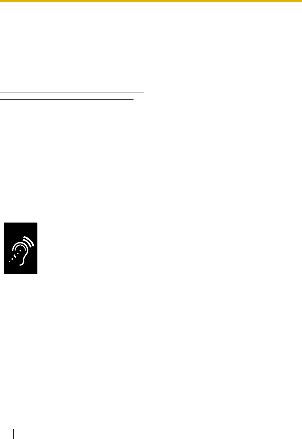
Compliance with TIA-1083 standard
T
Compatible with
Hearing Aid T-Coil
TIA-1083
Telephone handsets identified with
this logo have reduced noise and
interference when used with T-Coil
equipped hearing aids and cochlear
implants.
10 Operating Instructions Document Version 2011-10
Additional Information

Table of Contents
Before Operating the Telephone ..........................................................13
Accessory Information ...................................................................................................13
Location of Controls .......................................................................................................14
Screens ............................................................................................................................20
Status Icons .....................................................................................................................20
Soft Buttons and Soft Button Icons ..............................................................................21
Basic Operations .............................................................................................................23
Confirming Your Extension Number ...............................................................................23
Going off- and on-hook ...................................................................................................23
Adjusting the Volume .....................................................................................................23
Feature Operations ................................................................................25
Making Calls ....................................................................................................................25
Making a Call ..................................................................................................................25
Making a Call from the Phonebook List ..........................................................................25
Dialing by Using Call Logs .............................................................................................25
Redialing the Last Number You Dialed (Redial, Last Number) ......................................26
One-touch Dialing (KX-UT133/KX-UT136 only) .............................................................26
Receiving Calls ................................................................................................................27
Receiving a Call .............................................................................................................27
Rejecting Calls ...............................................................................................................27
Holding a Call ..................................................................................................................28
Receiving a Second Call (Answering Call Waiting) .....................................................29
Talking to Two Parties Alternately (Call Splitting) .......................................................29
Transferring a Call (Call Transfer) .................................................................................30
To Transfer with One Touch (One-touch Transfer) (KX-UT133/KX-UT136 only) ..........30
Mute ..................................................................................................................................30
Conference Call (Local Three-way Conference) ..........................................................31
Making a Conference Call ..............................................................................................31
Removing a Party from the Conference .........................................................................31
Ending a Conference Call ..............................................................................................31
Checking Messages ........................................................................................................32
Checking New Messages ...............................................................................................32
Checking Missed Calls ...................................................................................................32
Call Forwarding/Do Not Disturb .....................................................................................33
Logging in to or Logging out of a Group (KX-UT133/KX-UT136 only) .......................33
Logging in to or Logging out of an ACD (Automatic Call Distribution) Group .................33
Flexible Buttons (KX-UT133/KX-UT136 only) ...............................................................34
Customizing the Telephone ..................................................................35
Phonebook List ...............................................................................................................35
Adding a New Phonebook Entry ....................................................................................35
Adding a Phonebook Entry from the Incoming Call Log .................................................35
Editing a Phonebook Entry .............................................................................................35
Searching for a Phonebook Entry ..................................................................................36
Deleting a Phonebook Entry ...........................................................................................36
Export/Import Phonebook Entries ..................................................................................36
User Settings ...................................................................................................................37
Accessing the Settings ...................................................................................................37
Available Settings ...........................................................................................................38
Settings Details ..............................................................................................................40
Entering Characters ........................................................................................................48
Document Version 2011-10 Operating Instructions 11
Table of Contents

Web User Interface Programming .................................................................................56
Installation and Setup ............................................................................57
Attaching/Removing the Stand ......................................................................................57
Connections ....................................................................................................................60
Wall Mounting ..................................................................................................................63
Hooking the Handset ......................................................................................................68
Using a Headset ..............................................................................................................70
Setting Up the Unit ..........................................................................................................70
Maintaining the Unit ........................................................................................................71
Initializing the Unit ..........................................................................................................71
Restarting the Unit ..........................................................................................................71
Cleaning the Unit ............................................................................................................71
Appendix .................................................................................................72
Specifications ..................................................................................................................72
Troubleshooting ..............................................................................................................74
Common Issues and Solutions .......................................................................................74
Error Messages ..............................................................................................................76
Open Source Software ...........................................................................78
Index..............................................................................................................82
12 Operating Instructions Document Version 2011-10
Table of Contents
Before Operating the Telephone
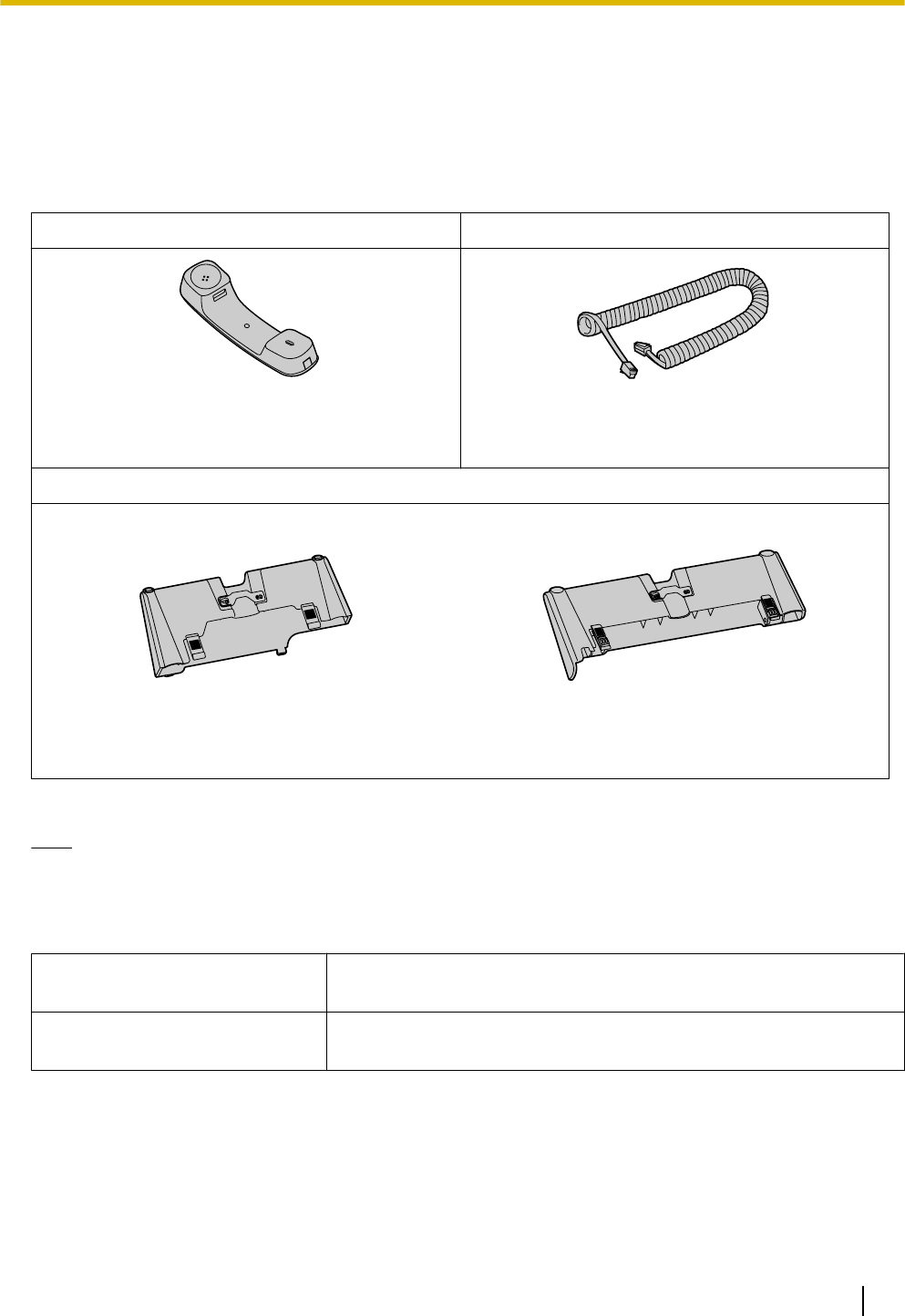
Accessory Information
Included Accessories*1
Handset (1) Handset Cord (1)
[Part No.]
Black model: PNLXQ1001Z
White model: PNLXQ1002Z
[Part No.]
Black model: PNJA1066Z
White model: PNJA1067Z
Stand (1)
For KX-UT113/KX-UT123:
[Part No.]
Black model: PNYLUT113BM
White model: PNYLUT113M
For KX-UT133/KX-UT136/KX-UT248:
[Part No.]
Black model: PNYLUT133BM
White model: PNYLUT133M
*1 For extra orders for the accessories, call toll-free: 1-800-332-5368. (For users in the United States only)
Note
•The illustrations may differ from the appearance of the actual product.
Optional Accessories
Optional AC Adaptor*1 •For users in the United States: KX-A239 (PQLV206)
•For users in Canada: KX-A239X (PQLV206)
Wall Mount Kit •For KX-UT113/KX-UT123: KX-A432
•For KX-UT133/KX-UT136/KX-UT248: KX-A433
*1 To order an optional AC adaptor, please order using the "KX-A239" model number.
Document Version 2011-10 Operating Instructions 13
Before Operating the Telephone
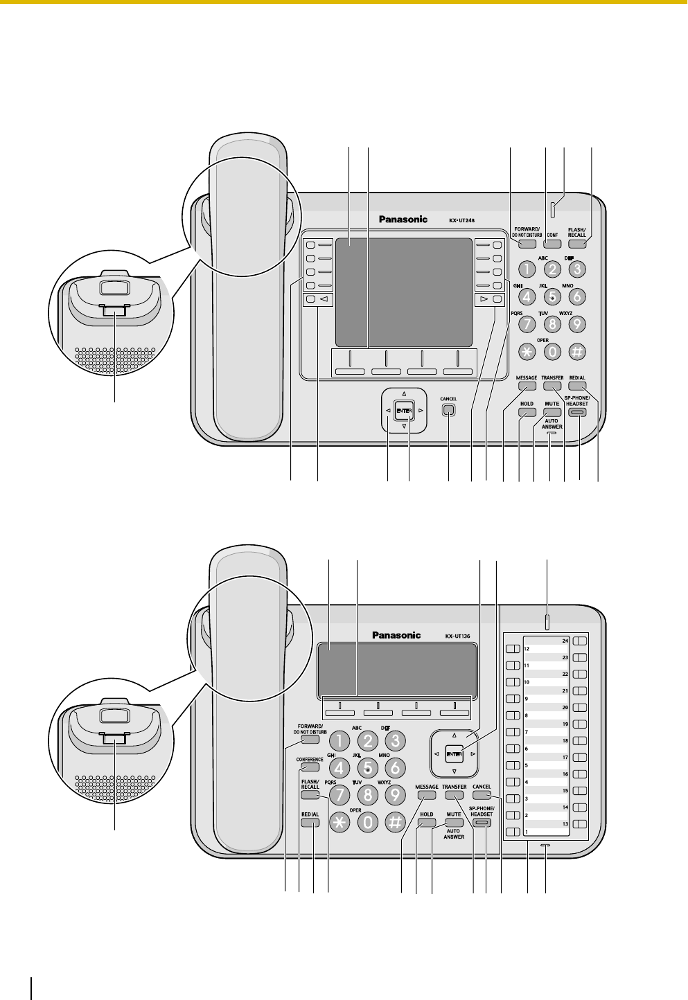
Location of Controls
Front View
For KX-UT248:
F
AEG J
SC D P
H
MR
B
L INK O
QSQ
For KX-UT136:
F
AE
BCD
KLM NOP QR
HGIJ
14 Operating Instructions Document Version 2011-10
Before Operating the Telephone
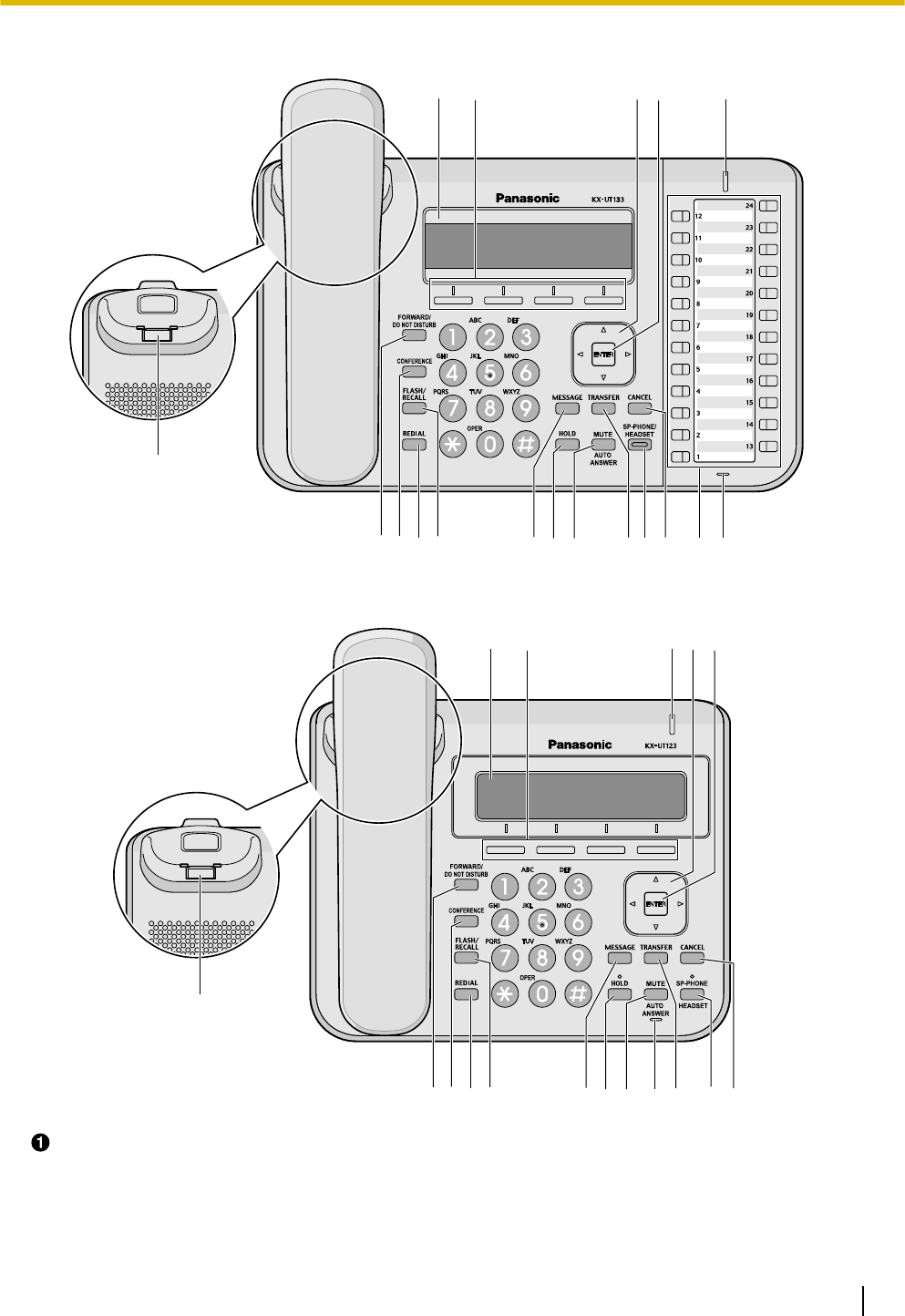
For KX-UT133:
F
AE
BCD
KLM NOP QR
HGIJ
For KX-UT113/KX-UT123:
F
AEB CD
KLM N OP
R
HIJG
LCD (Liquid Crystal Display)
KX-UT248 is equipped with a 4.4-inch LCD and LCD backlight.
KX-UT136 is equipped with a 6-Line LCD and LCD backlight.
KX-UT133 is equipped with a 3-Line LCD and LCD backlight.
KX-UT123 is equipped with a 3-Line LCD and LCD backlight.
Document Version 2011-10 Operating Instructions 15
Before Operating the Telephone

KX-UT113 is equipped with a 3-Line LCD.
Soft Buttons (S1 to S4)
S1 to S4 (located below the display) are used to select the item displayed on the bottom line of the display.
Navigator Key
Used to adjust the volume or select desired items.
ENTER
Used to assign the selected item.
Message/Ringer Lamp
When you receive a call or Hold Recall, the lamp flashes green.
When someone has left you a message, the lamp stays on red.
Handset Hook
Keeps the handset stable when the unit is mounted on a wall. For details, see "To Lock the Handset Hook
when the Unit is Wall Mounted (Page 68)".
FORWARD/DO NOT DISTURB
Used to set Call Forwarding or Do Not Disturb on your extension.
CONF (Conference)/CONFERENCE
Used to establish a local three-way conference.
REDIAL
Used to redial the last dialed number.
FLASH/RECALL
Used to disconnect the current call and make another call without hanging up.
MESSAGE
Used to access your voice mailbox.
HOLD
Used to put a call on hold.
When a call is on hold, the Hold lamp (KX-UT113/KX-UT123 only) flashes red.
MUTE/AUTO ANSWER
Used to receive an incoming call in hands-free mode or mute the microphone/handset during a
conversation.
TRANSFER
Used to transfer a call to another party.
SP-PHONE (Speakerphone)/HEADSET
Used for performing hands-free operations. When the SP-PHONE is used, the lamp on the SP-PHONE
(KX-UT133/KX-UT136/KX-UT248 only) or the lamp above the SP-PHONE (KX-UT113/KX-UT123 only)
turns red. When muted, the lamp flashes red.
CANCEL
Used to cancel the selected item.
Flexible Buttons/Flexible Button Lamps (KX-UT133/KX-UT136/KX-UT248 only)
Used to make or receive calls, or perform the feature that has been assigned to the button. The flexible
button lamp shows the status of each flexible button.
MIC
Used for hands-free conversation.
Page Keys (KX-UT248 only)
Used to switch the page of flexible buttons displayed. There are three pages of eight flexible buttons.
16 Operating Instructions Document Version 2011-10
Before Operating the Telephone
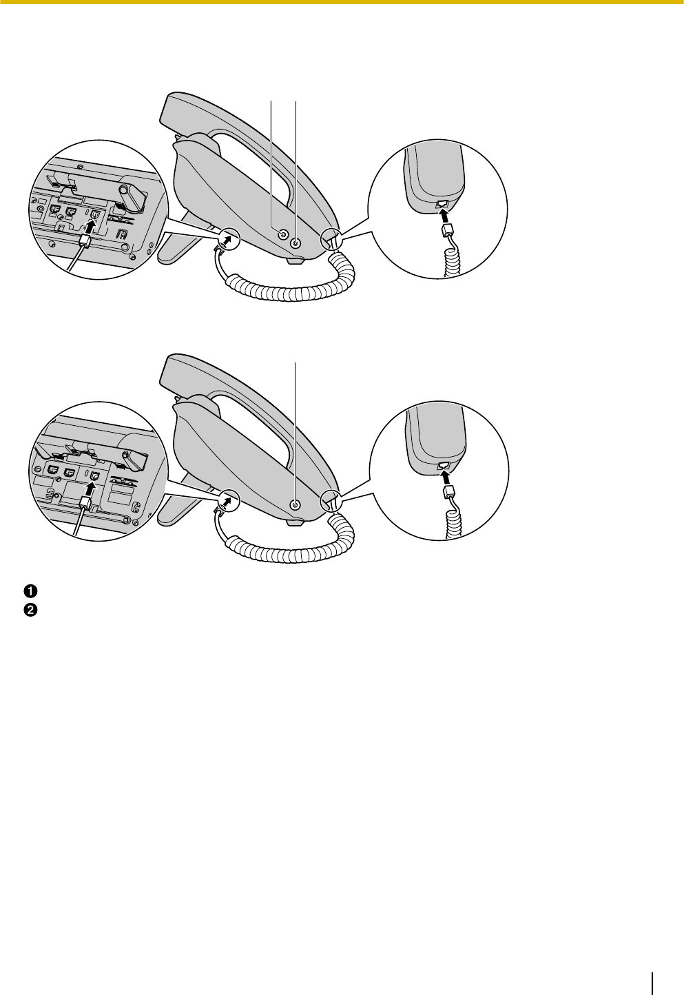
Left Side View
For KX-UT133/KX-UT136/KX-UT248:
BA
For KX-UT113/KX-UT123:
B
EHS Jack (KX-UT133/KX-UT136/KX-UT248 only)
Headset Jack
Document Version 2011-10 Operating Instructions 17
Before Operating the Telephone
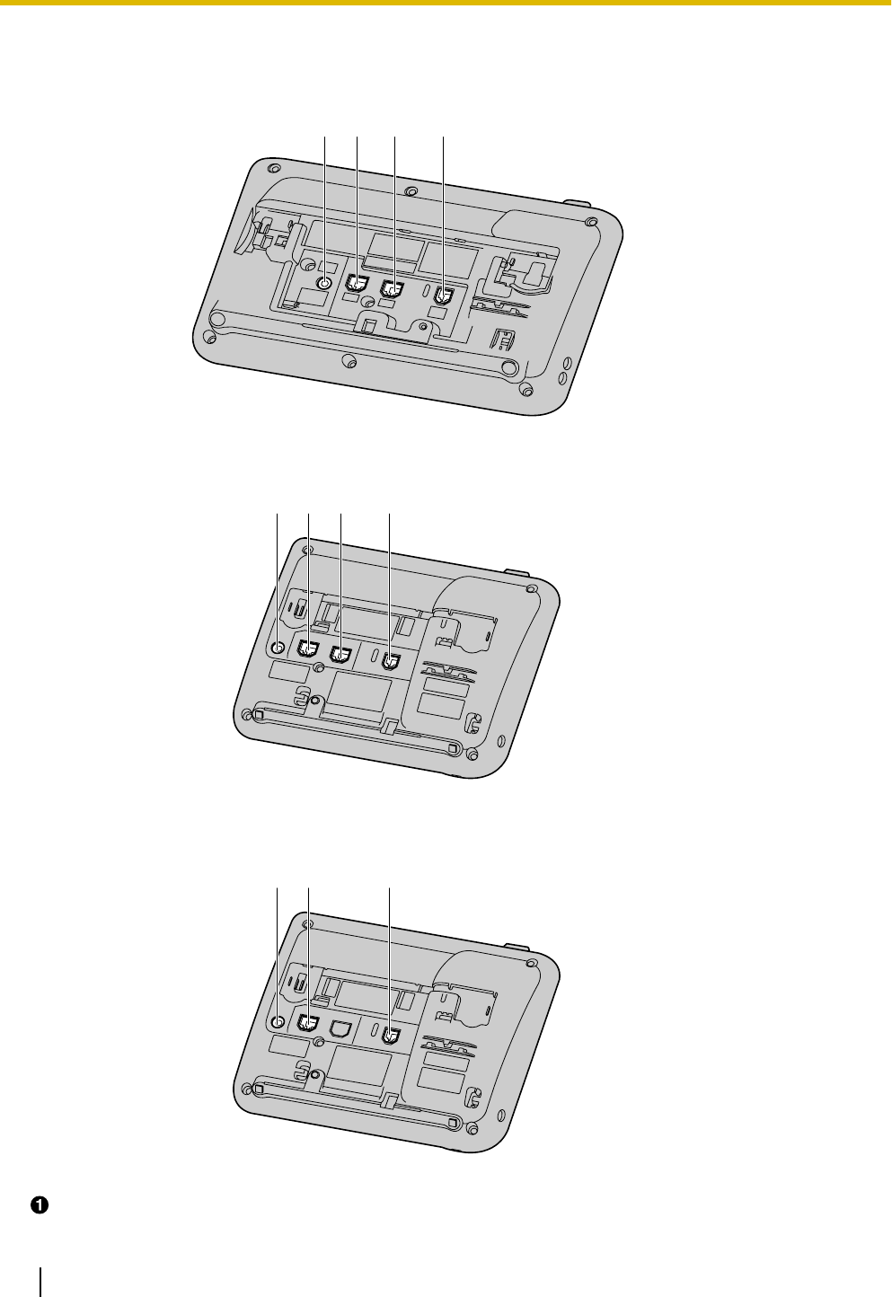
Bottom View
For KX-UT133/KX-UT136/KX-UT248:
CD
BA
For KX-UT123:
ACD
B
For KX-UT113:
AD
B
DC Jack
18 Operating Instructions Document Version 2011-10
Before Operating the Telephone

LAN Port
PC Port (KX-UT123/KX-UT133/KX-UT136/KX-UT248 only)
Handset Jack
Document Version 2011-10 Operating Instructions 19
Before Operating the Telephone
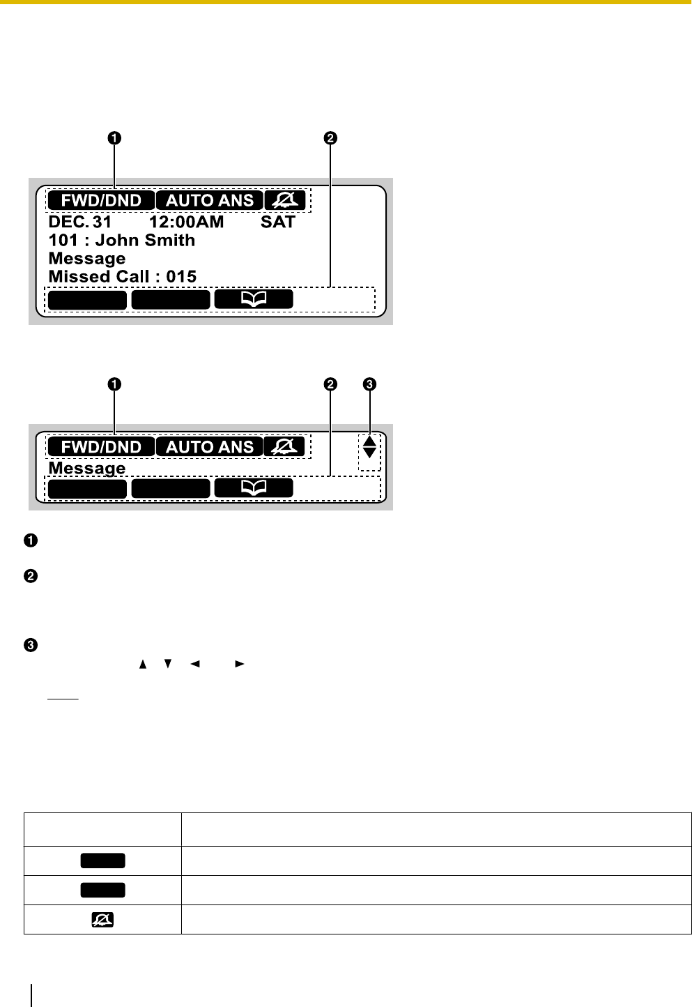
Screens
This section explains the buttons and icons that appear on the display.
For KX-UT136:
Setting Call Log
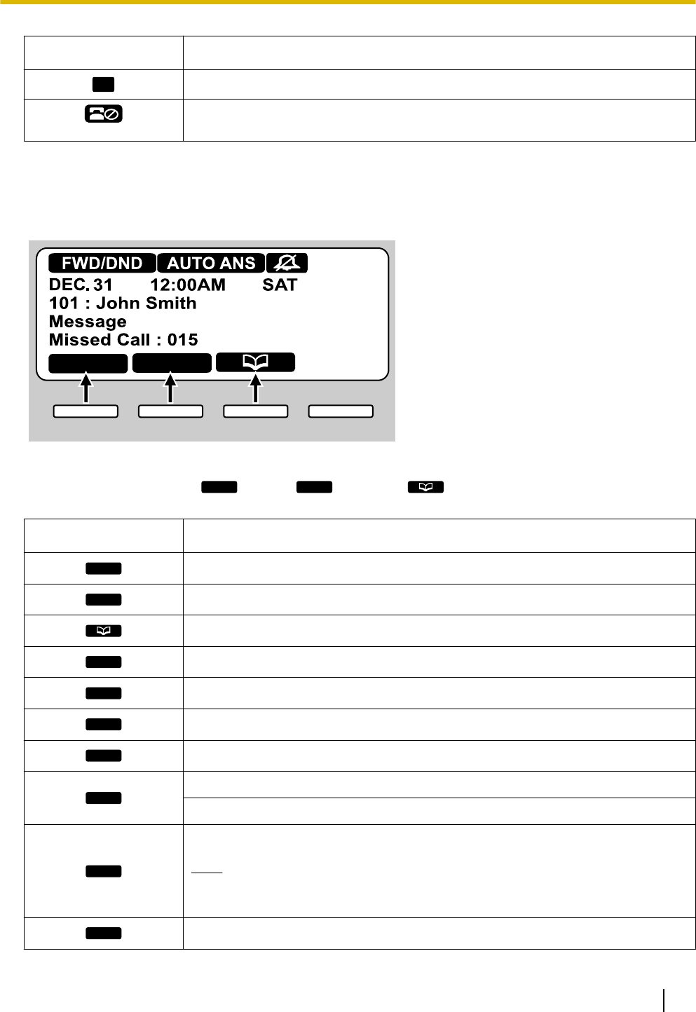
For KX-UT113/KX-UT123/KX-UT133:
Setting Call Log
Status Icons
Indicates the status of various features (Page 20).
Soft Button Icons
Indicate the functions that will be accessed when the corresponding buttons are pressed. The icons
displayed vary according to the state of the unit. (For example, the icons displayed while on a call are
different from the icons displayed while storing an entry in the phonebook).
Scroll Indicator
Indicates that [], [ ], [ ], or [ ] can be pressed to display the previous or next item.
Note
•Although the scroll indicator is not shown in the screen sample of the KX-UT136 above, it does
appear on some screens.
Status Icons
Icon Description
FWD/DND
Displayed when Call Forwarding or Do Not Disturb is enabled (Page 33).
AUTO ANS
Displayed when Auto Answer is enabled (Page 27).
Displayed when the ringer is turned off (Page 23).
20 Operating Instructions Document Version 2011-10
Before Operating the Telephone
Icon Description
ECO
Displayed when Eco mode is enabled (Page 40).
Displayed when registration to the SIP server has been lost. If this icon is
displayed, consult your administrator or dealer.
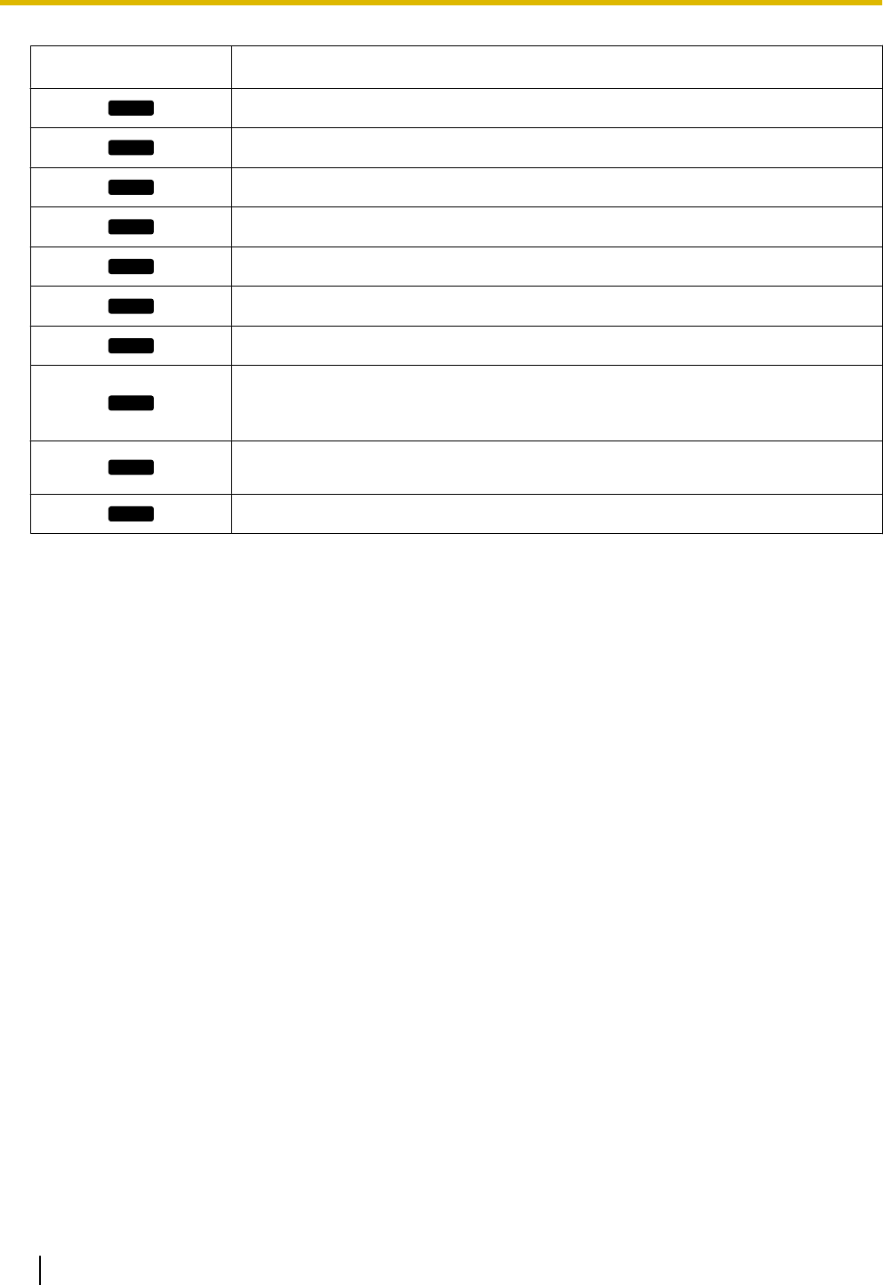
Soft Buttons and Soft Button Icons
By pressing a soft button (S1 to S4), you can access the function displayed directly above it.
Setting Call Log
S1 S2 S3 S4
In this manual, soft buttons are referred to by their corresponding icons.
In the example here, "Press
Setting
", "Press
Call Log
", or "Press " would indicate pressing S1, S2, or S3,
respectively.
Icon Description
Setting
Access the user setting menus (Page 37).
Call Log
Access the call log (Page 25).
Access the phonebook (Page 35).
Setup
Access the setup menus (Page 70).
Clear
Erase the number or character above the cursor (Page 25).
Search
Search for a phonebook entry (Page 25).
Menu
Edit a call log or phonebook entry (Page 26, Page 35).
OK
Confirm a transfer operation (Page 30).
Begin installation of a firmware update (Page 46).
Enter
Save or confirm the information shown on the display.
Note
•You can also use the physical ENTER button to perform the same
operation as this soft button.
Answer
Answer an incoming call (Page 23).
Document Version 2011-10 Operating Instructions 21
Before Operating the Telephone
Icon Description
Close
Close the incoming call screen and continue pre-dialing (Page 25).
Reject
Reject an incoming call (Page 27).
Blind
Perform a blind transfer (Page 30).
Erase
Erase the information shown on the display (Page 28, Page 36).
Save
Save the information shown on the display (Page 27, Page 35).
Call
Make a call (Page 25).
Edit
Edit the information shown on the display (Page 26, Page 27, Page 35).
Prefer
Assign the preferred number to dial among multiple registered phone numbers in
the same phonebook entry, when making a call using the phonebook
(Page 35).
Number
Display the telephone number when searching an entry in the phonebook
(Page 25).
Update
Update the firmware (Page 46).
22 Operating Instructions Document Version 2011-10
Before Operating the Telephone

Basic Operations
This section explains the basics of using the unit.
Confirming Your Extension
Number
In stand-by mode (i.e., when you do not have any active
calls), you can view the extension number and name
registered to the unit.
Going off- and on-hook
There are several ways to go off-hook and on-hook:
•Using the handset
•Using the [SP-PHONE] button
•Using the soft buttons
•For KX-UT133/KX-UT136, using a DN button
(flexible button)
Going off-hook
In this manual, when you see the phrase "go off-hook",
you can do any of the following:
•Lift the handset off of its cradle.
•Press [SP-PHONE] while the handset is on its
cradle. This enables hands-free mode.
•For KX-UT133/KX-UT136, press a DN button
(flexible button).
Note
•Certain soft buttons, such as
Answer
, function
like the [SP-PHONE] button.
•For details about DN buttons, see "Flexible
Buttons (KX-UT133/KX-UT136 only)
(Page 34)".
Going on-hook
In this manual, when you see the phrase "go on-hook",
you can do any of the following:
•Replace the handset on its cradle.
•Press [SP-PHONE], if you are in hands-free mode.
Hands-free Mode
In hands-free mode, you can talk and hear the other
party in a conversation without using the handset. This
mode is useful for performing other tasks during a
conversation, such as writing.
Enabling hands-free mode
You can enable hands-free mode in one of the following
ways:
•In stand-by mode, press [SP-PHONE].
•During a conversation while using the handset,
press [SP-PHONE]. You can then return the
handset to its cradle.
•When receiving an incoming call, press
Answer
.
•For KX-UT133/KX-UT136, in stand-by mode, press
an idle DN button (flexible button).
•For KX-UT133/KX-UT136, when receiving a call or
when a call is on hold, press the flashing green DN
button (flexible button) that corresponds to the call.
Canceling hands-free mode
You can cancel hands-free operation simply by lifting
the handset off its cradle.
Note
•For details about DN buttons, see "Flexible
Buttons (KX-UT133/KX-UT136 only)
(Page 34) ".
Off-hook monitor
During a two-party conversation with the corded
handset, you can allow other people to listen to the
conversation through the speaker while you continue
the conversation using the handset.
•Press [SP-PHONE], but do not return the handset
to its cradle.
•Press [SP-PHONE] again to cancel off-hook
monitor.
Note
•When off-hook monitor is active, replacing the
handset to its cradle enables hands-free mode.
•During a conference call, pressing
[SP-PHONE] simply enables hands-free mode.
The handset will be disabled.
Adjusting the Volume
You can adjust the ringer, handset, headset, and
speaker volume using [] and [ ] on the Navigator key.
Adjusting the ringer volume
When receiving a call, press [ ] or [ ].
Document Version 2011-10 Operating Instructions 23
Before Operating the Telephone

You can also adjust the ringer volume in the settings.
For details, see "Ringer (Page 40)".
Note
•When the ringer volume is turned all the way
down, "Off" is displayed. Also, is
displayed when the unit is in stand-by mode.
Adjusting the handset/headset/
speaker volume
Press [ ] or [ ] during a conversation when using the
handset, headset, or when you are in hands-free mode.
24 Operating Instructions Document Version 2011-10
Before Operating the Telephone
Feature Operations
Making Calls
This section explains the basic methods for making a
call.
Making a Call
1. In stand-by mode, go off-hook.
2. Enter the number you want to call.
3. Press [ENTER], or wait a few seconds for the
number to be dialed.
4. To end the call, go on-hook.
Pre-dialing
In stand-by mode, you can start dialing (max. 32 digits)
while still on-hook.
•To delete a number you entered, press
Clear
.
•To clear the entire number, press and hold
Clear
.
•To connect the call, go off-hook or press [ENTER].
Note
•For KX-UT133/KX-UT136, you can also press
an idle DN button (flexible button) to connect the
call. For details about DN buttons, see "Flexible
Buttons (KX-UT133/KX-UT136 only)
(Page 34)".
•For KX-UT113/KX-UT123, when pre-dialing
you can press
Call
instead of going off-hook.
If more than one line is available at your unit,
select the line to use, and then press [ENTER].
•If you receive an incoming call during
pre-dialing, the display changes to the incoming
call screen. For KX-UT133/KX-UT136, you can
close the incoming call screen by pressing
Close
, and continue pre-dialing.
Making a Call from the
Phonebook List
Scrolling through all entries
1. Press .
2. Press [ ] or [ ] to select an entry.
3. Go off-hook.
4. To end the call, go on-hook.
Note
•For KX-UT133/KX-UT136, you can also press
an idle DN button (flexible button) in step 3 to
connect the call. For details about DN buttons,
see "Flexible Buttons (KX-UT133/KX-UT136
only) (Page 34)".
•For KX-UT113/KX-UT123, you can press
Call
instead of going off-hook. If more than
one line is available at your unit, select the line
to use, and then press [ENTER].
•In step 2, if multiple phone numbers are stored
for the entry, you can press
Number
and then
select the phone number to call.
Searching by name
1. Press .
2. Press
Search
.
3. Enter the name (max. 12 characters) you want to
search for.
4. Press [ENTER].
The entry that matches your search appears.
5. Go off-hook.
6. To end the call, go on-hook.
Note
•For KX-UT113/KX-UT123, you can press
Call
instead of going off-hook. If more than
one line is available at your unit, select the line
to use, and then press [ENTER].
•For details about entering characters, see
"Entering Characters (Page 48)".
•In step 4, if multiple phone numbers are stored
for the entry, you can press
Number
and then
select the phone number to call.
•If you do not press any buttons for 1 minute, the
unit will return to stand-by mode.
Dialing by Using Call Logs
The last 30 incoming calls and outgoing calls are stored
in their respective logs, in order of newest to oldest call.
You can make calls to the numbers listed in the call logs.
1. Press
Call Log
.
2. Press [ ] or [ ] to select the call log type, and then
press [ENTER].
3. Press [ ] or [ ] to select the desired entry.
4. Go off-hook.
5. To end the call, go on-hook.
Document Version 2011-10 Operating Instructions 25
Feature Operations
Note
•For KX-UT133/KX-UT136, you can also press
an idle DN button (flexible button) in step 4 to
connect the call. For details about flexible
buttons, see "Flexible Buttons (KX-UT133/
KX-UT136 only) (Page 34)".
•For KX-UT113/KX-UT123, you can press
Call
instead of going off-hook. If more than
one line is available at your unit, select the line
to use, and then press [ENTER].
•You can add a call log entry to the phonebook.
See "Adding a Phonebook Entry from the
Incoming Call Log (Page 35)".
Editing a phone number before
dialing from the incoming call log
You can edit a phone number in the incoming call log
before using it to dial.
1. Press
Call Log
.
2. Press [ ] or [ ] to select "Incoming Call Log",
and then press [ENTER].
3. Press [ ] or [ ] to select the desired entry.
4. Do one of the following, depending on your unit:
For KX-UT113/KX-UT123 users
•Press
Menu
, select "Edit", and then press
[ENTER].
For KX-UT133/KX-UT136 users
•Press
Edit
.
5. Edit the number, and then go off-hook or press
Call
.
6. To end the call, go on-hook.
Redialing the Last Number You
Dialed (Redial, Last Number)
You can redial the last phone number that you dialed.
1. Press [REDIAL].
2. To end the call, go on-hook.
Note
•For KX-UT133/KX-UT136, to select a line to use
to redial, press the appropriate DN button
(flexible button) before you press [REDIAL].
For details about DN buttons, see "Flexible
Buttons (KX-UT133/KX-UT136 only)
(Page 34)".
•The unit may be configured to display the
outgoing call log instead of immediately
redialing. You can select an entry from the call
log to make a call (Page 25). For details, consult
your administrator or dealer.
One-touch Dialing (KX-UT133/
KX-UT136 only)
You can make a call with a One-touch operation if a
One-touch dialing button has been created for the
desired party. One-touch dialing buttons can also be
configured to access features of your phone system, if
available.
1. Go off-hook, and then press the One-touch dialing
button (flexible button).
2. To end the call, go on-hook.
Note
•A BLF (Busy Lamp Field) button (flexible button)
can also be used to call an extension simply by
pressing the button. For details, consult your
administrator or dealer.
•For details about flexible buttons such as
One-touch dialing buttons and BLF buttons, see
"Flexible Buttons (KX-UT133/KX-UT136 only)
(Page 34)".
26 Operating Instructions Document Version 2011-10
Feature Operations
Receiving Calls
This section explains the basic methods for receiving a
call.
Receiving a Call
1. Go off-hook.
2. To end the call, go on-hook.
Auto answer
You can have the unit automatically answer an
incoming call. The call is connected after a programmed
number of rings.
•To enable Auto Answer:
In stand-by mode, press [AUTO ANSWER] until
"Auto Answer On" appears.
•To disable Auto Answer:
In stand-by mode, press [AUTO ANSWER] until
"Auto Answer Off" appears.
Note
•When Auto Answer is enabled,
AUTO ANS
appears on the display in stand-by mode.
Rejecting Calls
You can reject an incoming call at your unit or set the
unit to reject certain calls.
Rejecting a call while receiving
1. When receiving an incoming call, press
Reject
.
Rejecting anonymous calls
You can set the unit to reject calls when the unit
receives a call without phone number.
To reject anonymous calls, the Block Anonymous Call
setting must be enabled through Web user interface
programming (Page 56). For details, consult your
administrator or dealer.
Note
•Rejected phone numbers will not be stored in
the incoming call log.
•Depending on the line an incoming call is
arriving on, the call may not be rejected.
Rejecting specific calls
You can set the unit to reject specific phone numbers.
Note
•Rejected phone numbers will not be stored in
the incoming call log.
Adding a phone number
You can store a maximum of 30 phone numbers you
want to reject in the rejection list of the unit.
1. In stand-by mode, press
Setting
.
2. Press [] or [ ] to select "Call Block", and then
press [ENTER].
3. Press
Add
.
4. Enter the telephone number (max. 32 digits), and
then press [ENTER].
Note
•To register additional telephone numbers,
repeat the procedure from step 3.
Adding a phone number from the incoming call
log
You can add a phone number by referring to the
incoming call log.
1. In stand-by mode, press
Call Log
.
2. Press [] or [ ] to select "Incoming Call Log",
and then press [ENTER].
3. Press [] or [ ] to select the entry with the phone
number you want to reject.
4. Press
Save
.
5. Press [ ] or [ ] to select "Call Block", and then
press [ENTER].
6. Press [ ] or [ ] to select "Yes", and then press
[ENTER].
Note
•If you do not press any buttons for 1 minute, the
unit will return to stand-by mode.
Editing a stored phone number
1. In stand-by mode, press
Setting
.
2. Press [ ] or [ ] to select "Call Block", and then
press [ENTER].
3. Press [ ] or [ ] to select the phone number you
want to edit, and then press
Edit
.
4. Edit the phone number as necessary, and then
press [ENTER].
Document Version 2011-10 Operating Instructions 27
Feature Operations

Note
•If you do not press any buttons for 1 minute, the
unit will return to stand-by mode.
Deleting a stored phone number
1. In stand-by mode, press
Setting
.
2. Press [ ] or [ ] to select "Call Block", and then
press [ENTER].
3. Press [] or [ ] to select the phone number you
want to delete, and then press
Erase
.
4. Press [ ] or [ ] to select "Yes", and then press
[ENTER].
Note
•If you do not press any buttons for 1 minute, the
unit will return to stand-by mode.
Holding a Call
You can put a call on hold by holding the call at your
extension.
To hold the current call
1. Press [HOLD], and then go on-hook.
Note
•For KX-UT133/KX-UT136, if Automatic Call
Hold is enabled on your unit, the call will
also be put on hold if you press a DN button
(flexible button) other than the one for the
current call. For details, consult your
administrator or dealer.
To retrieve a call on hold at your extension
1. Go off-hook.
2. Do one of the following, depending on your unit:
For KX-UT113/KX-UT123 users
•Press [HOLD].
For KX-UT133/KX-UT136 users
•Press the green flashing DN button (flexible
button).
Note
•If a call is not retrieved within a specified time,
you will hear an alarm as a reminder (Hold
Recall).
•For details about DN buttons, see "Flexible
Buttons (KX-UT133/KX-UT136 only)
(Page 34)".
28 Operating Instructions Document Version 2011-10
Feature Operations

Receiving a Second Call
(Answering Call Waiting)
During a conversation, if a second call arrives, you will
hear a call waiting tone.
You can answer the second call by disconnecting or
holding the current call.
To disconnect the current call and then talk to
the new party
1. Go on-hook while hearing the call waiting tone.
2. Go off-hook.
To hold the current call and then talk to the new
party
For KX-UT113/KX-UT123 users
1. Press [HOLD] while hearing the call waiting tone.
For KX-UT133/KX-UT136 users
1. Press [HOLD] while hearing the call waiting tone.
2. Press the green flashing DN button (flexible button).
Note
•For KX-UT133/KX-UT136, if Automatic Call
Hold is enabled on your unit, you do not need
to press [HOLD] in step 1. The call is
automatically put on hold when you press the
DN button. For details, consult your
administrator or dealer.
•For details about DN buttons, see "Flexible
Buttons (KX-UT133/KX-UT136 only)
(Page 34)".
Talking to Two Parties
Alternately (Call Splitting)
When you are talking to one party and have another
party on hold, you can switch the call on hold and the
current call.
1. Press [HOLD] during a conversation.
2. Call the second party.
3. Do one of the following, depending on your unit:
For KX-UT113/KX-UT123 users
•Press [HOLD].
For KX-UT133/KX-UT136 users
•Press [HOLD], and then press the green
flashing DN button (flexible button) that
corresponds to the other party on hold.
Note
•For KX-UT133/KX-UT136, if Automatic Call
Hold is enabled on your unit, you do not need
to press [HOLD] in step 3. The call is
automatically put on hold when you press the
DN button. For details, consult your
administrator or dealer.
•For details about DN buttons, see "Flexible
Buttons (KX-UT133/KX-UT136 only)
(Page 34)".
Document Version 2011-10 Operating Instructions 29
Feature Operations

Transferring a Call (Call
Transfer)
You can transfer a call to another destination (extension
or outside party).
To transfer
1. Press [TRANSFER] during a conversation.
2. Call the party you want to transfer the call to.
3. Wait until the other party answers to announce the
transfer. (This step can be omitted.)
4. Press
OK
.
Note
•If On-hook Transfer is enabled on your unit, you
can simply go on-hook in step 4 instead of
pressing
OK
. For details, consult your
administrator or dealer.
To do a blind transfer
1. Press
Blind
during a conversation.
2. Call the party you want to transfer the call to.
3. Go on-hook.
To Transfer with One Touch
(One-touch Transfer)
(KX-UT133/KX-UT136 only)
1. Press the BLF button (flexible button) during a
conversation.
2. Wait until the other party answers to announce the
transfer. (This step can be omitted.)
3. Press
OK
.
Note
•If On-hook Transfer is enabled on your unit, you
can simply go on-hook in step 3 instead of
pressing
OK
. For details, consult your
administrator or dealer.
•For details about flexible buttons, see "Flexible
Buttons (KX-UT133/KX-UT136 only)
(Page 34)".
Mute
You can mute your voice during a conversation. While
the mute feature is turned on, you will be able to hear
the other party, but the other party will not be able to
hear you.
The built-in microphone, handset, and headset are all
muted when the mute feature is turned on.
To mute/unmute
1. Press [MUTE].
30 Operating Instructions Document Version 2011-10
Feature Operations

Conference Call (Local
Three-way Conference)
During a conversation, you can add an additional party
to your call and establish a conference call.
Notice
•Your phone system may support advanced
conference features, such as conference calls
with four or more parties. In this case, the
procedures for handling a conference call may
be different from those explained in this section.
For details about your phone system, consult
your administrator or dealer.
Making a Conference Call
1. Press [CONFERENCE] to put the current call on
hold.
2. Call the party you want to add to the conversation.
3. After the called party answers, press
[CONFERENCE] to begin the conference call.
Removing a Party from the
Conference
During a conference, you can remove other parties from
the conference. However, this operation is available
only during conference calls you initiate.
For KX-UT113/KX-UT123 users
1. During a conference call, press [HOLD].
•The second party is put on hold, but you can
continue talking to the first party.
2. Go on-hook.
•The first party is disconnected.
3. Press [HOLD].
•You can continue the conversation with the
second party.
Note
•To disconnect the second party instead of the
first party, press [HOLD] 2 times in step 1.
•Once you have pressed [HOLD], the
conference cannot be reestablished.
For KX-UT133/KX-UT136 users
1. During a conference call, press [HOLD].
•The other parties are put on hold.
2. Press the DN button (flexible button) that
corresponds to the party you want to disconnect.
•A conversation is established with the party you
want to disconnect.
3. Go on-hook.
•The party is disconnected.
4. Press the DN button (flexible button) that
corresponds to the remaining party.
•You can continue the conversation with the
remaining party.
Note
•Once you have pressed [HOLD], the
conference cannot be reestablished.
•For details about DN buttons, see "Flexible
Buttons (KX-UT133/KX-UT136 only)
(Page 34)".
Ending a Conference Call
1. Go on-hook during a conference.
Document Version 2011-10 Operating Instructions 31
Feature Operations

Checking Messages
Checking New Messages
When you receive a voice message, "Message"
appears on the display, and the Message/Ringer lamp
turns red.
You can check your new messages by accessing your
mailbox.
1. Press [MESSAGE].
2. If the unit has multiple lines, press [] or [ ] to select
the line on which is displayed, and then go
off-hook.
Checking Missed Calls
When there are new missed calls, "Missed Call:
XXX" appears on the display. ("XXX" indicates the
number of missed calls.)
1. Press
Call Log
.
2. Press [] or [ ] to select "Incoming Call Log",
and then press [ENTER].
3. Press [ ] or [ ] to select the missed call.
Note
•In the incoming call log, "Not Answered" is
displayed on missed calls. For KX-UT113/
KX-UT123/KX-UT133, you must press [ ] to
see this.
•For details about making calls from the call log,
see "Dialing by Using Call Logs (Page 25)".
•A check mark is displayed next to answered
calls and missed calls that you have already
checked.
32 Operating Instructions Document Version 2011-10
Feature Operations
Call Forwarding/Do Not
Disturb
You can have incoming calls automatically forwarded
to another destination. You can also have incoming
calls rejected (Do Not Disturb).
Note
•When Call Forwarding or Do Not Disturb is
enabled,
FWD/DND
appears on the display in
stand-by mode.
To access the FWD/DND settings
1. In stand-by mode, press
Setting
or [FORWARD/DO
NOT DISTURB].
•If you press [FORWARD/DO NOT DISTURB],
continue to step 3.
2. Press [ ] or [ ] to select "FWD/DND Setting", and
then press [ENTER].
3. If line selection is available, press [] or [ ] to select
the desired line, and then press [ENTER].
4. Press [ ] or [ ] to select the type of FWD or DND
setting to apply, and then press [ENTER].
5. Configure the settings as necessary (Page 41).
Logging in to or Logging
out of a Group
(KX-UT133/KX-UT136
only)
Logging in to or Logging out of
an ACD (Automatic Call
Distribution) Group
If the SIP server supports ACD and you are assigned
to an ACD group, you can log in to or log out of the
group.
1. In stand-by mode, press the flexible button
assigned as the ACD Log-in/Log-out button.
Note
•The flexible button's light indicates the status as
follows:
Off: logged in to the ACD group
Red On: logged out of the ACD group
Document Version 2011-10 Operating Instructions 33
Feature Operations

Flexible Buttons
(KX-UT133/KX-UT136
only)
The flexible buttons on the unit can be customized to be
used to make or receive calls or as feature buttons.
These buttons are configured by your administrator or
dealer.
The following types of flexible buttons are available:
DN (Directory Number)
Seizes the line assigned to the DN button. When a
call arrives at the DN button, pressing the button
answers the call.
Lamp Indication
•Off: Idle
•Green on: You are on a call using the DN
button.
•Flashing green rapidly: A call is being
received.
•Flashing green slowly: A call is on hold.
•Red on: A shared line is in use or on hold
(private) at another unit.
•Flashing red slowly: A shared line is on hold
(normal) at another unit.
Note
•A ring tone can be assigned to each DN
button through Web user interface
programming. When a call arrives at a DN
button, the ring tone assigned to that button
plays. For details, consult your
administrator or dealer.
•A shared line is a line that can be used by
multiple units. This is an optional feature
and may not be supported on your phone
system.
One-Touch
Calls the party or accesses a feature assigned to
the button. See "One-touch Dialing (KX-UT133/
KX-UT136 only) (Page 26)".
Headset
Enables or disables talking using the headset.
Lamp Indication
•Off: Headset off
•Red on: Headset on
BLF (Busy Lamp Field)
Calls the extension assigned to the button. During
a conversation, a BLF button can be used to
transfer calls to the assigned extension (Page 30).
A BLF button’s lamp also shows the current status
of the assigned extension.
Lamp Indication
•Off: The assigned extension is idle.
•Red on: The assigned extension is using the
line.
•Flashing red rapidly: The assigned extension
is receiving an incoming call.
If enabled through Web user interface
programming, pressing the button answers the
call (Directed Call Pickup).
Note
•BLF (Busy Lamp Field) is an optional
feature and may not be supported on your
phone system.
ACD
Logs in to or logs out of a group when ACD
(Automatic Call Distribution) is enabled (Page 33).
Lamp Indication
•Off: Logged in
•Red on: Logged out
Note
•ACD is an optional feature and may not be
supported on your phone system.
34 Operating Instructions Document Version 2011-10
Feature Operations

Customizing the Telephone
Phonebook List
Adding a New Phonebook Entry
You can add a maximum of 500 (for KX-UT123/
KX-UT133/KX-UT136) or 100 (for KX-UT113)
phonebook entries to the unit.
To make a call from the phonebook, see "Making a Call
from the Phonebook List (Page 25)".
1. Press .
2. Press
Add
.
3. Enter a name (max. 24 characters), and then press
[ENTER].
4. Press [ ] or [ ] to select the phone number type
(A to E) or "Ringtone X", and then press
[ENTER].
5. Do one of the following, depending on your
selection in the previous step:
If you selected a phone number type
•Enter the phone number (max. 32 digits), and
then press [ENTER].
If you selected "Ringtone X"
•Select a ringtone to play when you receive a call
from this party, and then press [ENTER].
6. To add another phone number to the entry, repeat
the procedure from step 4.
7. Press
Save
.
Note
•If you store multiple phone numbers in the entry,
you can assign the preferred number to use
when you call this party. In step 4, select the
desired number, and then press
Prefer
.
•If you do not press any buttons for 1 minute, the
unit will return to stand-by mode.
Adding a Phonebook Entry from
the Incoming Call Log
You can add new phonebook entries from the incoming
call log.
1. Press
Call Log
.
2. Press [] or [ ] to select "Incoming Call Log",
and then press [ENTER].
3. Press [ ] or [ ] to select the desired call log entry,
and then press
Save
.
4. Select "Phonebook", and then press [ENTER].
5. Enter a name (max. 24 characters), and then press
[ENTER].
6. Press [ ] or [ ] to select the phone number type
(A to E) or "Ringtone X", and then press
[ENTER].
7. Do one of the following, depending on your
selection in the previous step:
If you selected a phone number type
•Enter the phone number (max. 32 digits), and
then press [ENTER].
If you selected "Ringtone X"
•Select a ringtone to play when you receive a call
from this party, and then press [ENTER].
8. To add another phone number to the entry, repeat
the procedure from step 6.
9. Press
Save
.
Note
•If a name is stored in the call log, it is
automatically entered in step 5.
•If you store multiple phone numbers in the entry,
you can assign the preferred number to use
when you call this party. In step 6, select the
desired number, and then press
Prefer
.
•If you do not press any buttons for 1 minute, the
unit will return to stand-by mode.
Editing a Phonebook Entry
You can edit the information stored in phonebook
entries.
1. Press .
2. Press [ ] or [ ] to display the desired entry, or press
Search
and search for the desired entry (Page 36).
3. Do one of the following, depending on your unit:
For KX-UT113/KX-UT123 users
•Press
Menu
, select "Edit", and then press
[ENTER].
For KX-UT133/KX-UT136 users
•Press
Edit
.
4. Press [] or [ ] to select the item you want to edit,
and then press [ENTER].
Document Version 2011-10 Operating Instructions 35
Customizing the Telephone
5. Edit the item as necessary, and then press
[ENTER].
6. Press
Save
.
Note
•If you store multiple phone numbers in the entry,
you can assign the preferred number to use
when you call this party. In step 4, select the
desired number, and then press
Prefer
.
•If you do not press any buttons for 1 minute, the
unit will return to stand-by mode.
Searching for a Phonebook
Entry
You can search the phonebook for the desired entry.
1. Press .
2. Press
Search
.
3. Enter the name you want to search for, and then
press [ENTER].
Deleting a Phonebook Entry
You can delete phonebook entries.
1. Press .
2. Press [ ] or [ ] to display the desired entry, or press
Search
and search for the desired entry (Page 36).
3. Do one of the following, depending on your unit:
For KX-UT113/KX-UT123 users
•Press
Menu
, select "Erase", and then press
[ENTER].
For KX-UT133/KX-UT136 users
•Press
Erase
.
4. Press [ ] or [ ] to select "Yes", and then press
[ENTER].
Export/Import Phonebook
Entries
You can export the phonebook entries through the Web
user interface to your computer as a tab separated
value file. This makes it possible to add and edit
phonebook entries using a spreadsheet application or
text editor on your computer. After editing, the file
should be imported into the unit.
Also, phonebook entries exported from one unit can be
imported into another, which makes it easy to share
phonebook entries.
To export/import entries, consult your administrator or
dealer.
Notice
•Entries deleted on your computer are not
deleted from the unit’s phonebook when
importing. Erase unnecessary entries with your
unit, not through the Web user interface.
•Phone calls cannot be made or received while
phonebook entries are being imported or
exported.
36 Operating Instructions Document Version 2011-10
Customizing the Telephone

User Settings
You can configure various settings to customize the behavior of the unit.
This section explains how to configure the settings using the unit.
Accessing the Settings
1. In stand-by mode, press
Setting
.
2. Press [ ] or [ ] to select the desired setting category, and then press [ENTER].
3. Configure the settings as necessary.
Document Version 2011-10 Operating Instructions 37
Customizing the Telephone

Available Settings
Ringer Ringer Volume Page 40
Ringtone Page 40
ECO Mode Page 40
LCD Contrast Page 40
Back Light Page 41
Display Lock Page 41
FWD/DND Setting Do Not Disturb Page 41
FWD All Page 41
FWD Busy Page 41
FWD No Ans Page 42
Language Page 42
Date and Time Page 43
Information Display Page 43
Network Settings Network DHCP Page 44
DNS Page 44
DNS1*1 Page 44
DNS2*1 Page 44
STATIC Page 44
IP Address Page 44
Subnet mask Page 44
Default Gateway Page 44
DNS1 Page 44
DNS2 Page 44
VLAN Enable VLAN Page 44
IP Phone Page 44
PC*2 Page 45
Speed/Duplex LAN port Page 45
PC port*2 Page 45
Embedded web Page 45
Network Test Page 45
Default Setting Factory Setting Page 46
IP Reset Page 46
Restart Page 46
Firmware version Page 46
38 Operating Instructions Document Version 2011-10
Customizing the Telephone

Settings Details
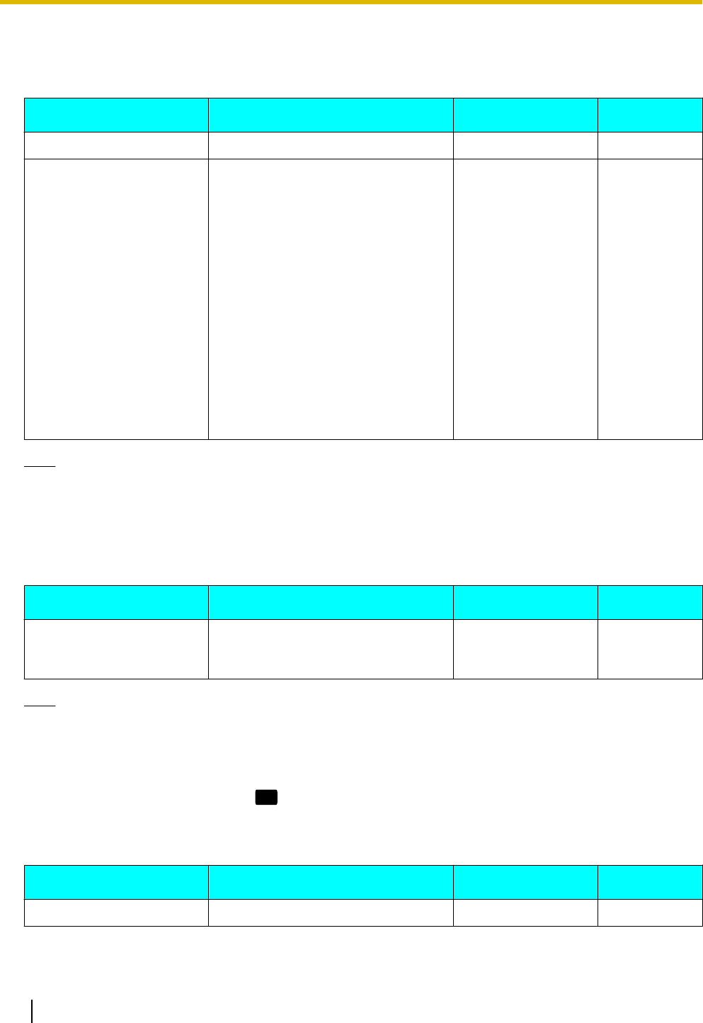
Ringer
Setting Description Value Range Default
Ringer Volume Adjust the ringer volume. Level 0 to 6 Level 3
Ringtone (current setting
confirmation)
For KX-UT133/KX-UT136, you can
listen to the ring tones. Ring tones
can be assigned to DN buttons
(flexible buttons, Page 34) through
Web user interface programming
(Page 56), but they cannot be
assigned directly from the unit. For
details about which ring tones are
assigned or if you want to change an
assigned ring tone, consult your
administrator or dealer.
For KX-UT113/KX-UT123, select a
ring tone to use for incoming calls.
If multiple lines are available at your
unit, you must first select which line
to use the ring tone for.
Ringtone 1–
Ringtone 32
Ringtone 1
Note
•The preset melodies in this product are used with permission of © 2009 Copyrights Vision Inc.
•Ringtone 20 to Ringtone 24 are the same as Ringtone 1.
•Ring tones can also be assigned to individual entries in the phonebook list (Page 35).
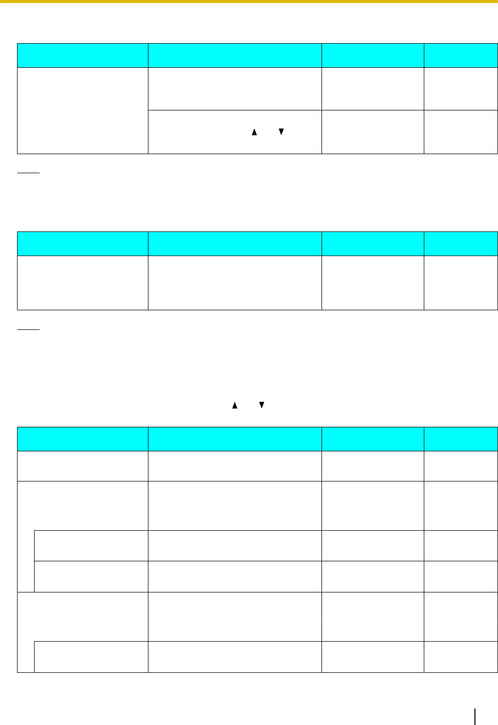
ECO Mode
Setting Description Value Range Default
ECO Mode Enabling this mode reduces the
amount of electricity consumed by
the unit.
On, Off Off
Note
•When ECO mode is enabled, the Speed/Duplex setting (Page 45) changes as follows:
–Speed/Duplex: "10M-Full"
–PC port cannot be used.
•When the Eco mode setting is changed, the unit will restart.
•When Eco mode is enabled,
ECO
is displayed while the unit is in stand-by mode.
LCD Contrast
Setting Description Value Range Default
LCD Contrast Change the contrast of the display. Level 1 to 6 Level 3
40 Operating Instructions Document Version 2011-10
Customizing the Telephone
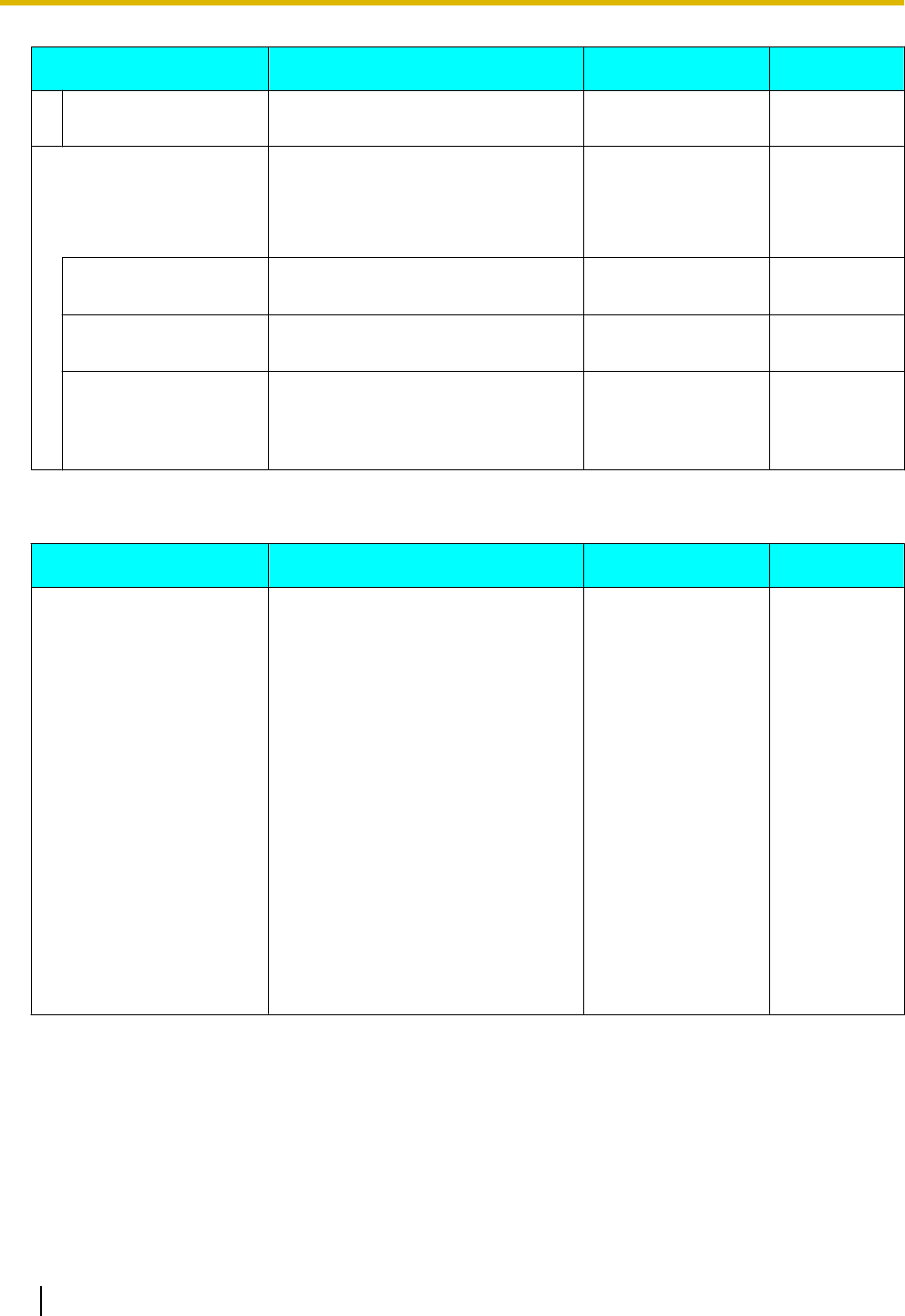
Back Light (KX-UT123/KX-UT133/KX-UT136 only)
Setting Description Value Range Default
Back Light Change the settings for the backlight. Always On
Automatic
Always Off
Automatic
If you select "Always On" or
"Automatic", press [ ] or [ ] to
adjust the brightness.
Level 1 to 3 Level 3
Note
•When "Automatic" is selected, the backlight turns off when the phone returns to an idle state.
Display Lock
Setting Description Value Range Default
Display Lock Lock access to your call log and
phonebook list by entering your
extension PIN (Personal
Identification Number).
On, Off Off
Note
•The extension PIN can be configured through Web user interface programming. For details, consult
your administrator or dealer.
FWD/DND Setting
If multiple lines are available at your unit, press [] or [ ] to select the line to apply the settings to when you
select "FWD/DND Setting".
Setting Description Value Range Default
Do Not Disturb Enable DND (Do Not Disturb) to
reject all incoming calls.
On, Off Off
FWD All Forward all incoming calls to a
specified destination.
— —
On/Off Enable or disable the "FWD All"
setting.
On, Off Off
Phone Number Specify the number to forward calls
to when "FWD All" is enabled.
1–32 digits —
FWD Busy Forward incoming calls to a specified
destination when you are on a call.
— —
On/Off Enable or disable the "FWD Busy"
setting.
On, Off Off
Document Version 2011-10 Operating Instructions 41
Customizing the Telephone
Setting Description Value Range Default
Phone Number Specify the number to forward calls
to when "FWD Busy" is enabled.
1–32 digits —
FWD No Ans Forward incoming calls to a specified
destination if you do not answer after
a specified number of rings.
— —
On/Off Enable or disable the "FWD No
Ans" setting.
On, Off Off
Phone Number Specify the number to forward calls
to when "FWD No Ans" is enabled.
1–32 digits —
Ring count After you specify the phone number
to forward calls to, enter the number
of times the unit will ring before
forwarding the call.
0, 2–20 3
Language
Setting Description Value Range Default
Language Select the language to use for the
display.
Čeština
Dansk
Deutsch (DE)
English (UK)
English (US)
Español
Français
Français (Canada)
Hrvatski
Italiano
Magyar
Nederlands
Polski
Português
Slovenčina
Svenska
Ελληνικα
Русский
Українська
(Depends on
your country/
area)
42 Operating Instructions Document Version 2011-10
Customizing the Telephone
Date and Time
Setting Description Value Range Default
Date and Time Set the date and time. Date*1: dd/mm/yyyy
or mm/dd/yyyy
Time*2: 00:00–23:59
or 12:00–11:59 AM/
PM
—
*1 Pressing [#] switches the date format.
*2 If the time format is not assigned in the configuration data, you can change the time format (12-hour or 24-hour) by pressing [*].
If the time format is set to 12-hour time in the configuration data, you can change the AM/PM setting by pressing [*].
Note
•Daylight-saving time can be set through Web user interface programming. For details, consult your
administrator or dealer.
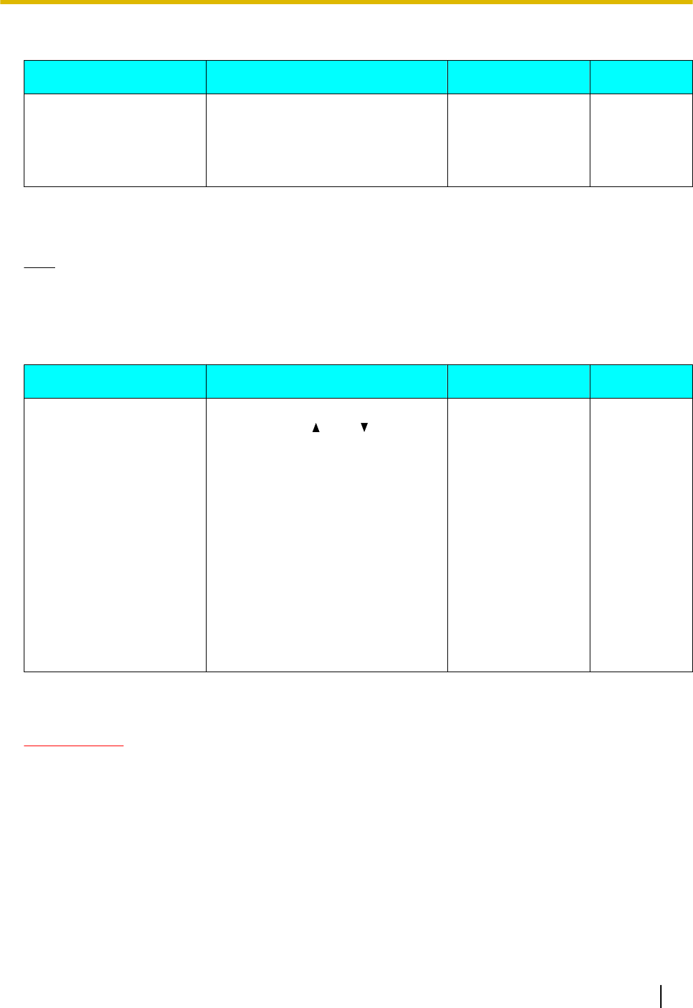
Information Display
Setting Description Value Range Default
Information Display View a variety of information about
the unit. Press [ ] and [ ] to display
the various settings. The following
settings can be viewed:
•Registration status to the SIP
server
•IP address
•Subnet mask address
•Default gateway address
•IP address of the DNS server 1
•IP address of the DNS server 2
•ACS status
•Display lock status
•Firmware version
•MAC address
— —
Network Settings
IMPORTANT
We recommend configuring these settings with your administrator or dealer. Network settings can also be
configured through Web user interface programming (Page 56). Contact your administrator or dealer for
further information.
Document Version 2011-10 Operating Instructions 43
Customizing the Telephone
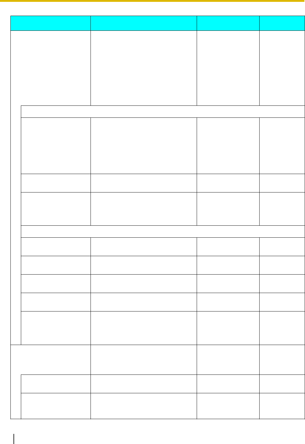
Setting Description Value Range Default
Network Configure the basic network settings.
If you select "DHCP", you must then
select whether the DNS setting is
configured automatically or
manually. If you select "STATIC",
you must manually specify the IP
address, subnet mask, default
gateway, and DNS servers.
DHCP, STATIC —
When DHCP is selected
DNS Select whether the DNS server
information should be obtained
automatically (i.e., provided by the
DHCP server) or if you will specify it
manually.
If you select "Manual", see "DNS1"
and "DNS2" below.
Manual, Automatic Automatic
DNS1*1 (Manual DNS
only)
Enter the IP address of the primary
DNS server.
xxx.xxx.xxx.xxx —
DNS2*1 (Manual DNS
only)
Enter the IP address of the
secondary DNS server.
If a secondary DNS server is not
required, leave this item blank.
xxx.xxx.xxx.xxx —
When STATIC is selected
IP Address*1 Enter the IP address to assign to the
unit.
xxx.xxx.xxx.xxx —
Subnet mask*1 Enter the subnet mask for your
network.
xxx.xxx.xxx.xxx —
Default Gateway*1 Enter the IP address of the default
gateway for your network.
xxx.xxx.xxx.xxx —
DNS1*1 Enter the IP address of the primary
DNS server.
xxx.xxx.xxx.xxx —
DNS2*1 Enter the IP address of the
secondary DNS server.
If a secondary DNS server is not
required, leave this item blank.
xxx.xxx.xxx.xxx —
VLAN Configure the VLAN (Virtual LAN)
settings.
— —
Enable VLAN Select whether to enable the VLAN
functionality.
Yes, No No
IP Phone Specify the necessary settings for
using the phone features over a
VLAN.
— —
44 Operating Instructions Document Version 2011-10
Customizing the Telephone
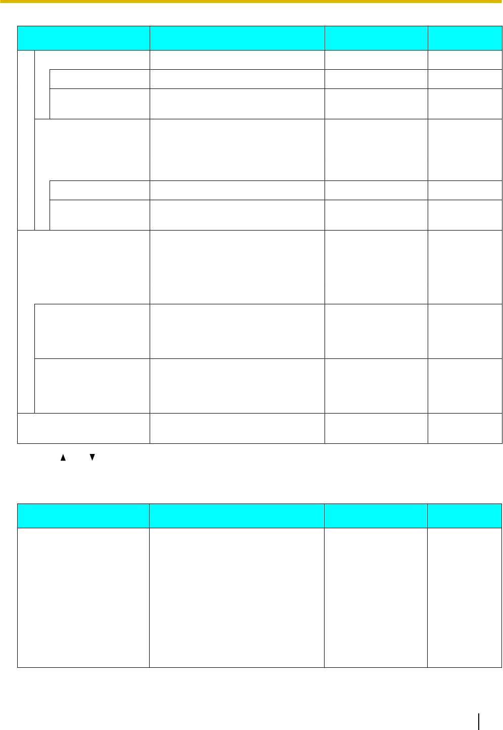
Setting Description Value Range Default
VLAN ID Specify the VLAN ID. 1–4094 2
Priority Specify the priority of packets sent
from this unit.
0–7 7
PC (KX-UT123/
KX-UT133/KX-UT136
only)
Specify the necessary settings for
using a PC over a VLAN.
— —
VLAN ID Specify the VLAN ID. 1–4094 1
Priority Specify the priority of packets sent
from this unit.
0–7 0
Speed/Duplex Select the connection mode
(combination of link speed and
duplex mode) of the LAN port and PC
port.
— —
LAN port Select the connection mode of the
LAN port.
Auto, 10M-Full,
10M-Half,
100M-Full,
100M-Half
Auto
PC port (KX-UT123/
KX-UT133/KX-UT136
only)
Select the connection mode of the
PC port.
Auto, 10M-Full,
10M-Half,
100M-Full,
100M-Half
Auto
Embedded web Enable or disable Web User
Interface Programming.
On, Off Off
*1 Press [ ] and [ ] to switch between these items.
Network Test
Setting Description Value Range Default
Network Test Confirm whether other network
devices (e.g., SIP server, routers,
switching hubs) respond to network
requests. When you select this item,
enter the IP address of the device to
which you want to test the
connection.
If a device does not respond, first
check the unit's network settings, and
then check the device's network
settings and connection.
xxx.xxx.xxx.xxx —
Document Version 2011-10 Operating Instructions 45
Customizing the Telephone
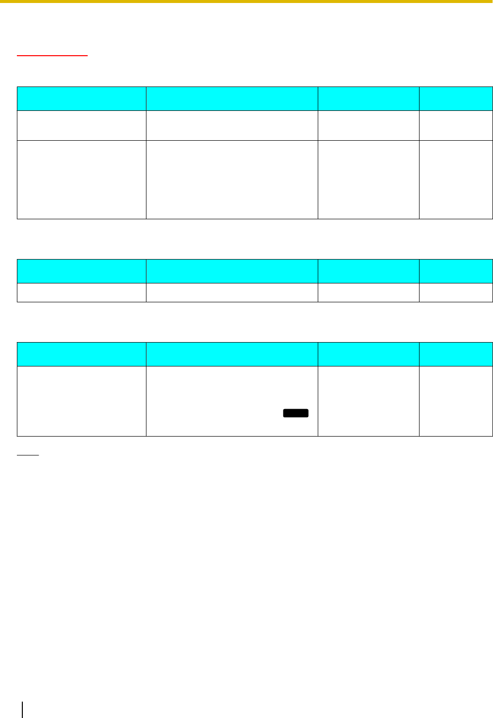
Default Setting
IMPORTANT
We recommend configuring these settings with your administrator or dealer. Contact your administrator or
dealer for further information.
Setting Description Value Range Default
Factory Setting Reset all settings to their
factory-shipment state.
— —
IP Reset Reset the following settings to their
default values:
•Network Settings (Page 43)
For details about the Web settings
that are reset, consult your
administrator or dealer.
— —
Restart
Setting Description Value Range Default
Restart Restart the unit (Page 71). — —
Firmware version
Setting Description Value Range Default
Firmware version View the version of the currently
installed firmware. If a newer version
is available, its version is also
displayed. In this case, press
Update
to update the firmware.
— —
Note
•Your phone system dealer may offer new features or an improved version of the unit's software from
time to time. If you set the unit software update setting to manual mode through the Web user interface,
you need to download the update when "Update version. Press OK." is displayed. Contact your
administrator or dealer for further information.
46 Operating Instructions Document Version 2011-10
Customizing the Telephone
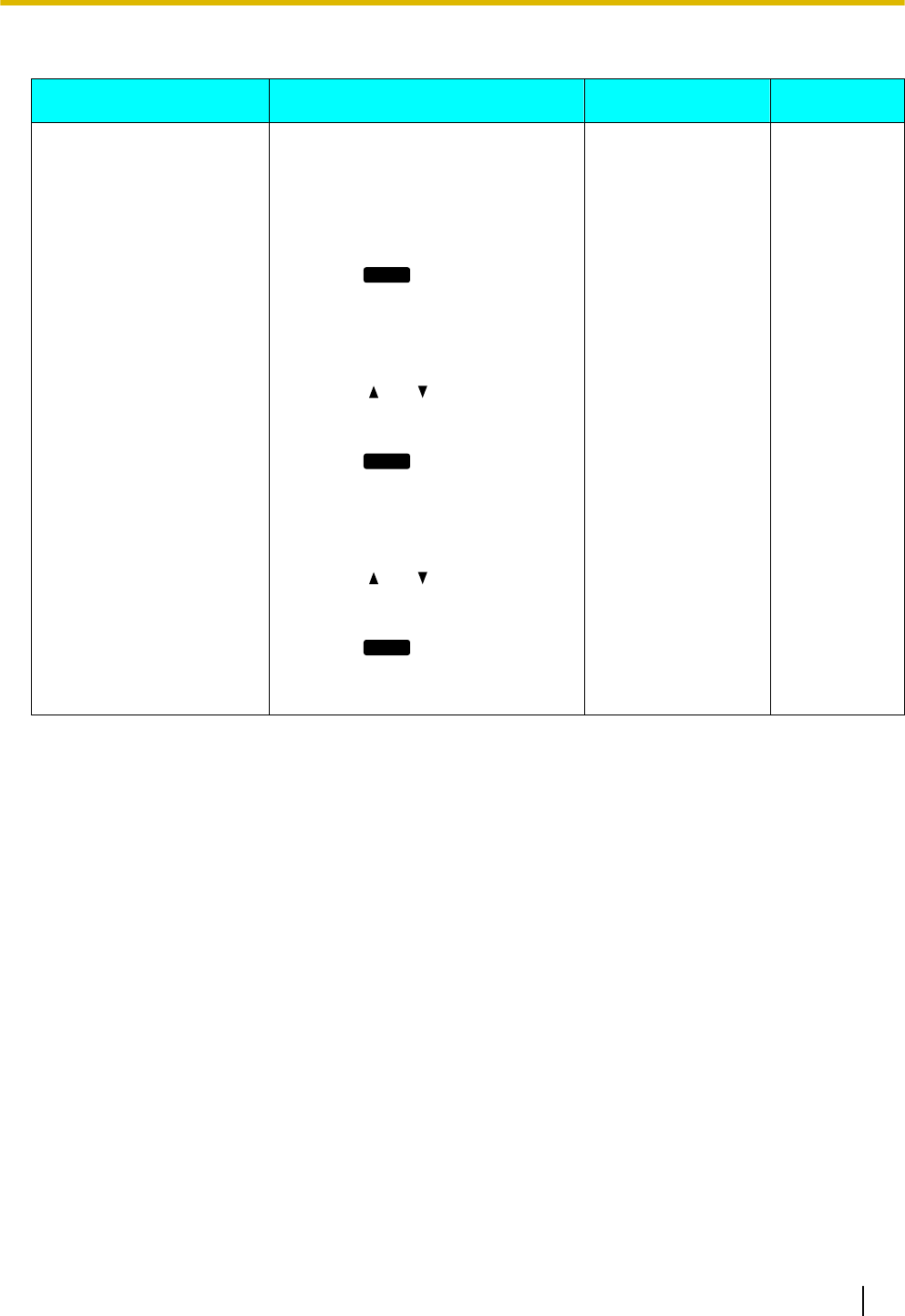
Call Block
Setting Description Value Range Default
Call Block Register telephone numbers so that
calls received from those numbers
are blocked. You can also delete
registered numbers.
To register
1. Press
Add
.
2. Enter the telephone number to
block, and then press [ENTER].
To edit
1. Press [ ] or [ ] to select the
blocked telephone number to
edit.
2. Press
Edit
.
3. Edit the number as necessary,
and then press [ENTER].
To delete
1. Press [ ] or [ ] to select the
blocked telephone number to
delete.
2. Press
Erase
.
3. Select "Yes", and then press
[ENTER].
— —
Document Version 2011-10 Operating Instructions 47
Customizing the Telephone
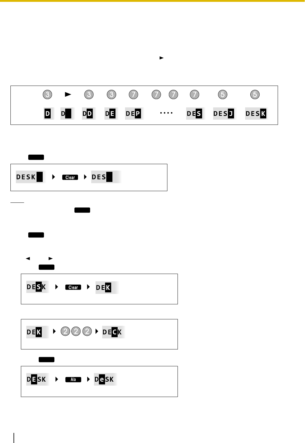
Entering Characters
The dial keys are used to enter characters and numbers. Each dial key has multiple characters assigned to it.
(For example, A, B and C are assigned to the 1 key.)
To enter a character, press the corresponding dial key until the character you want appears. To enter another
character that is assigned to the same key, first press [ ] to move the cursor to the right.
Example
To enter "DESK", press the keys as follows:
Display:
Input:
(right)
For details about the characters assigned to each key, see "Character Tables (Page 50)".
Deleting characters
Press
Clear
to delete the last character entered.
Note
•Press and hold
Clear
to delete all entered text.
Switching between uppercase and lowercase
Press
A/a
to switch between uppercase entry and lowercase entry.
Modifying entered text
Use [ ] and [ ] to move the cursor to where you want to modify the text. Then, modify the text as follows:
•Press
Clear
to delete the character under the cursor.
•Press a dial key to insert a character at the cursor’s location.
•Press
A/a
to change the case of the character under the cursor.
48 Operating Instructions Document Version 2011-10
Customizing the Telephone

Note
•If the maximum number of characters has been entered, entering another character will overwrite the
character under the cursor.
•If the entered texts spans two or more lines, you can also move the cursor using [] and [ ].
Character entry modes
The six character entry modes let you enter a variety of characters.
The following character modes are available:
•Latin (ABC)
•Numeric (0–9)
•Greek (ΑΒΓ)
•Extended 1 (AÄÅ)
•Extended 2 (SŚŠ)
•Cyrillic (АБВ)
For details about which characters are available in each mode, see "Character Tables (Page 50)".
To select a character mode
1. When entering characters, press
1/A/?
.
2. Press [ ] or [ ] to select the desired character entry mode.
3. Press [ENTER].
Note
•Depending on the type of information you are entering, you cannot change character modes. For
example, when you are entering a phone number, only numeric mode is available.
Document Version 2011-10 Operating Instructions 49
Customizing the Telephone
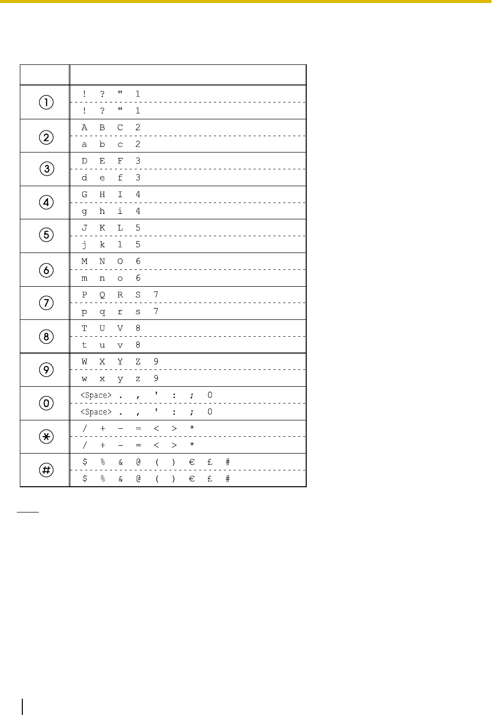
Character Tables
ABC (Latin)
Button
Characters
Note
•For each button, the upper row shows the characters entered in uppercase mode, and the lower row
shows the characters entered in lowercase mode.
50 Operating Instructions Document Version 2011-10
Customizing the Telephone
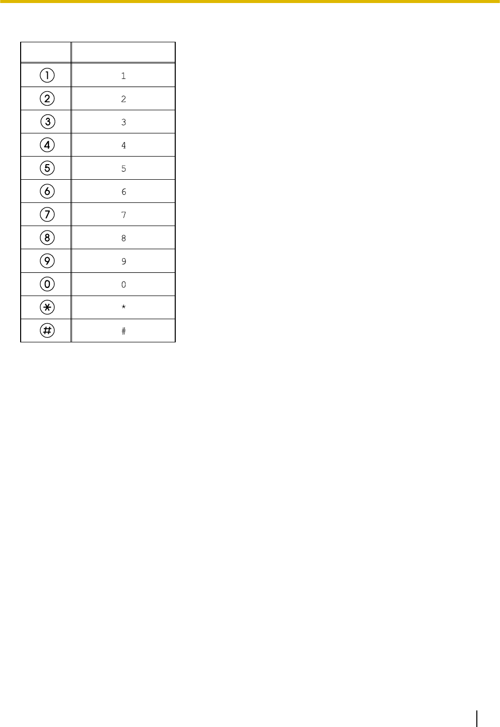
0–9 (Numeric)
Button
Characters
Document Version 2011-10 Operating Instructions 51
Customizing the Telephone
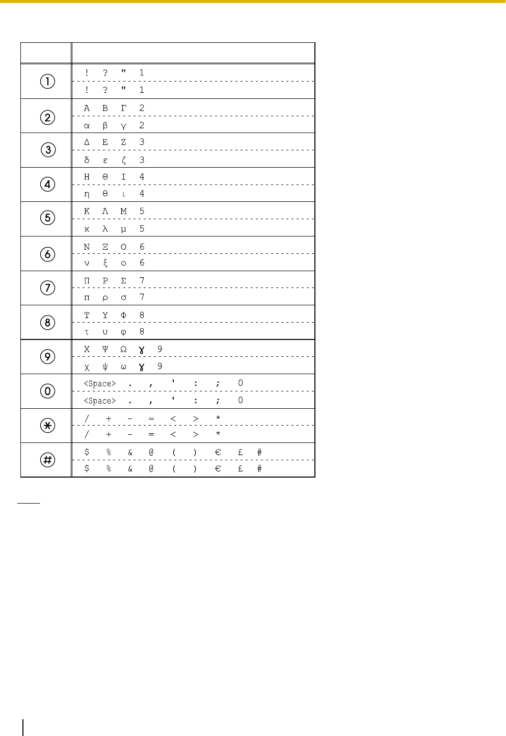
ΑΒΓ (Greek)
Button
Characters
Note
•For each button, the upper row shows the characters entered in uppercase mode, and the lower row
shows the characters entered in lowercase mode.
52 Operating Instructions Document Version 2011-10
Customizing the Telephone
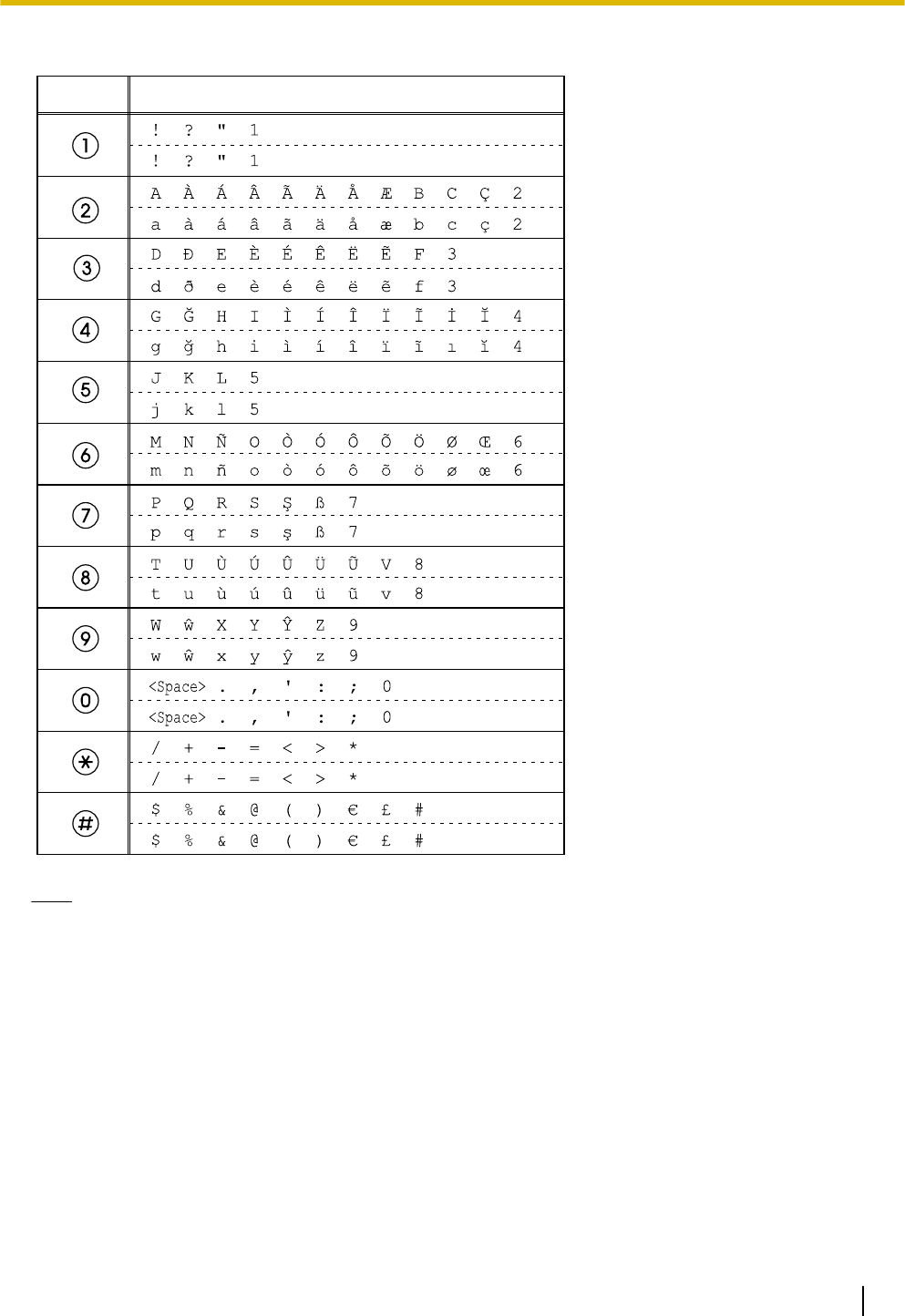
AÄÅ (Latin Extended 1)
Button
Characters
Note
•For each button, the upper row shows the characters entered in uppercase mode, and the lower row
shows the characters entered in lowercase mode.
Document Version 2011-10 Operating Instructions 53
Customizing the Telephone
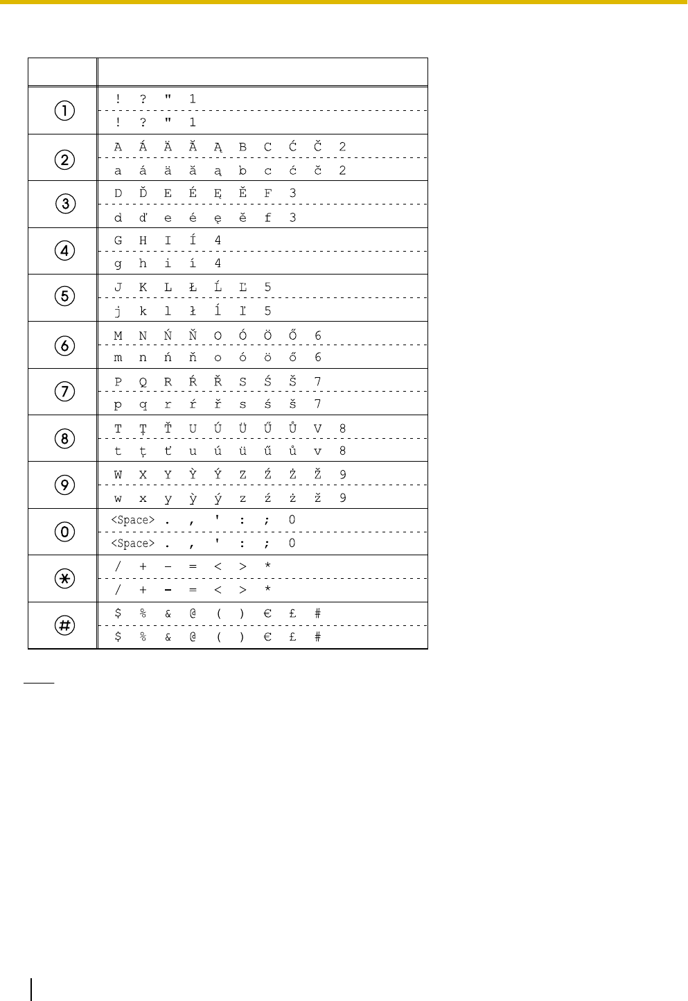
SŚŠ (Latin Extended 2)
Button
Characters
Note
•For each button, the upper row shows the characters entered in uppercase mode, and the lower row
shows the characters entered in lowercase mode.
54 Operating Instructions Document Version 2011-10
Customizing the Telephone
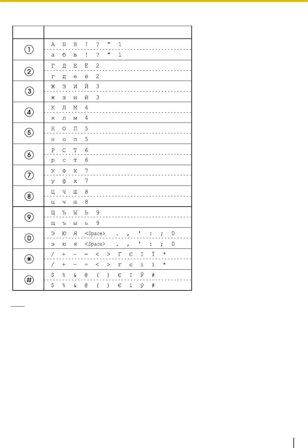
АБВ (Cyrillic)
Button
Characters
Note
•For each button, the upper row shows the characters entered in uppercase mode, and the lower row
shows the characters entered in lowercase mode.
Document Version 2011-10 Operating Instructions 55
Customizing the Telephone

Web User Interface
Programming
The unit provides a Web-based interface for configuring
various settings and features, including some that are
not programmable directly from the unit. The following
list contains some useful features that are
programmable through the Web user interface.
For details, consult your administrator or dealer.
•Basic network settings*1 (Page 43)
•User password (for access to Web user interface)
•HTTP authentication settings
•Date and time settings*1 (Page 43)
•Default outgoing line
•Call rejection phone numbers*1 (Page 47)
•Block caller ID
•Block anonymous calls
•Do Not Disturb*1 (Page 41)
•Call forward*1 (Page 41)
•Flexible button settings (Page 34) (DN, One-Touch,
Headset, etc. KX-UT133/KX-UT136 only)
•Key click tone
•Extension PIN
•Phonebook import and export (Page 36)
*1 These settings can also be configured directly through the unit.
Notice
•Each time you want to access the Web user
interface, you must enable Web programming
(Page 45).
56 Operating Instructions Document Version 2011-10
Customizing the Telephone
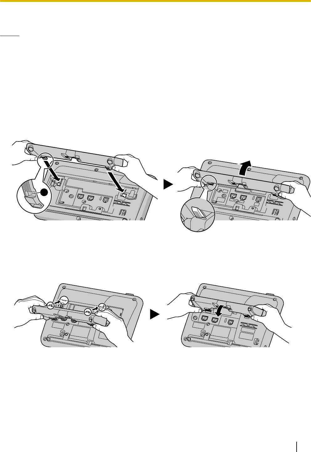
Installation and Setup
Notice
•Panasonic assumes no responsibility for injuries or property damage resulting from failures arising out of
improper installation or operation inconsistent with this documentation.
Attaching/Removing the Stand
Attaching the Stand
For KX-UT133/KX-UT136/KX-UT248:
1. Insert the catches (
1
) of the stand into hooks located in the unit.
2. Gently push the stand in the direction indicated until it locks into place.
The stand will be mounted in the high position.
A
For KX-UT113/KX-UT123:
1. Insert the catches of the stand into hooks located in the unit.
2. Gently push the stand in the direction indicated until it locks into place.
The stand will be mounted.
Removing the Stand
For KX-UT133/KX-UT136/KX-UT248:
1. Hold the stand with both hands.
Document Version 2011-10 Operating Instructions 57
Installation and Setup
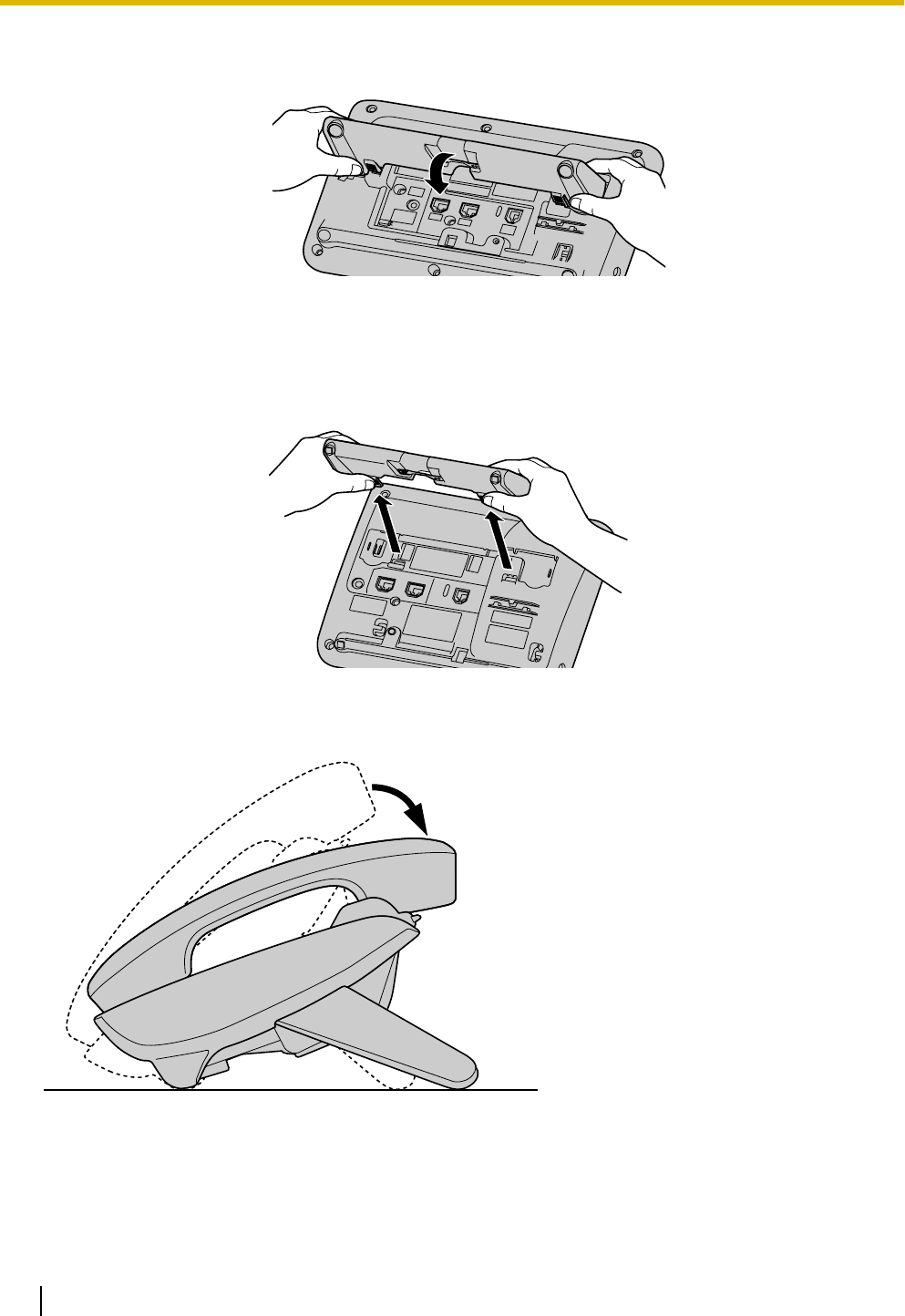
2. Gently rotate the stand in the direction indicated until it is released.
For KX-UT113/KX-UT123:
1. Remove the stand in the direction indicated while pushing the catches of the stand with both hands as
shown.
Adjusting from High to Low Position (KX-UT133/KX-UT136/KX-UT248 only)
58 Operating Instructions Document Version 2011-10
Installation and Setup
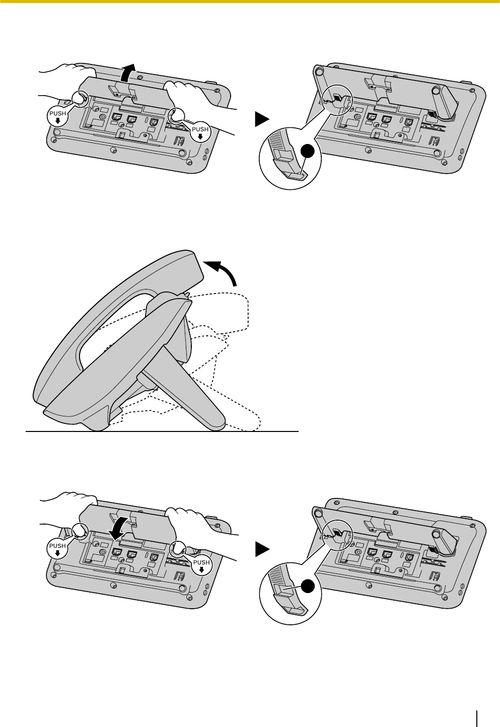
1. Tilt the stand in the direction indicated while pushing the PUSH mark with both hands as shown until it
locks into the low position (
2
).
B
Adjusting from Low to High Position (KX-UT133/KX-UT136/KX-UT248 only)
1. Tilt the stand in the direction indicated while pushing the PUSH mark with both hands as shown until it
locks into the high position (
1
).
A
Document Version 2011-10 Operating Instructions 59
Installation and Setup
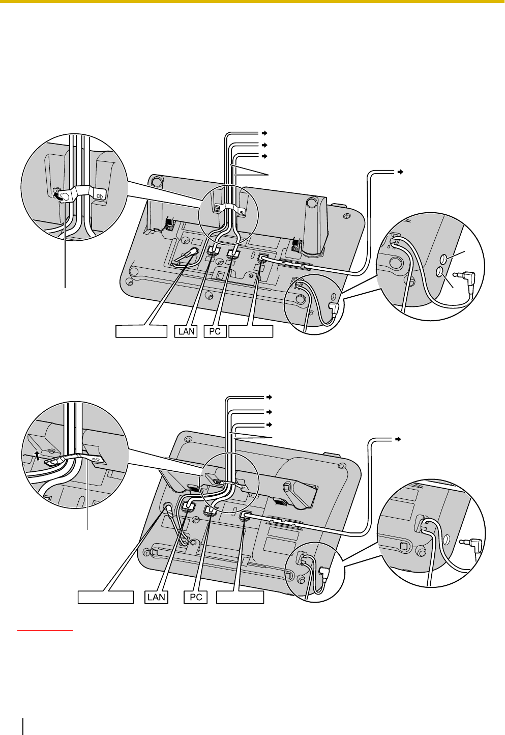
Connections
This section explains the ports and connectors on the unit.
Connections for AC Adaptor/LAN/PC
For KX-UT133/KX-UT136/KX-UT248:
To a Switching Hub
To a PC
Optional AC adaptor
AC adaptor
Clamp
Handset
To a handset jack
(handset)
Ethernet cables
A
B
A
B
EHS jack
Headset jack
Headset
For KX-UT113/KX-UT123:
To a Switching Hub
To a PC (KX-UT123 only)
To a handset jack
(handset)
Optional AC adaptor
AC adaptor
Headset
Handset
Clamp
Ethernet cables
CAUTION
Optional AC Adaptor
•Use the following Panasonic AC adaptor:
–For users in the United States: KX-A239 (PQLV206)
–For users in Canada: KX-A239X (PQLV206)
60 Operating Instructions Document Version 2011-10
Installation and Setup
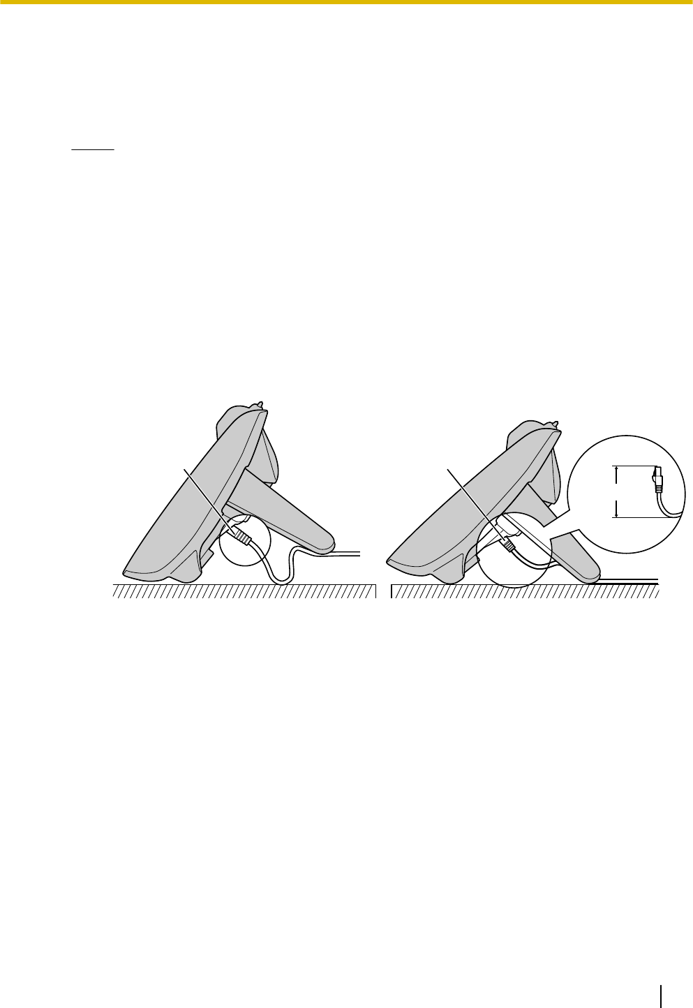
•The AC adaptor is used as the main disconnect device. Ensure that the AC outlet is installed near
the unit and is easily accessible.
When connecting a headset
•Ensure that the headset cord has slack and is not pulled tight during use to prevent damage to the
connectors.
Notice
•It is recommended that you use one of the following headsets:
–Wired headsets
Panasonic KX-TCA400 or KX-TCA430
–EHS headsets (KX-UT133/KX-UT136/KX-UT248 only)
Plantronics® Savi® Talk, Voyager™, or CS series
When selecting Ethernet cables (not included)
•Use flexible, high-quality, snagless (without strain relief) cables. Do not use cables with coating
that may tear or crack when bent.
To prevent damage to the cables, use cables that do not protrude from the bottom of the base.
Connect the cables as shown in the following illustration.
Ethernet cableEthernet cable
60 mm (2
3/8 in)
or less
Incorrect Correct
•Use a straight CAT 5 (or higher) Ethernet cable (not included) that is 6.5 mm (1/4 in) in diameter or
less.
When connecting to a switching hub
•If PoE is available, an AC adaptor is not needed.
•For KX-UT113/KX-UT123/KX-UT133/KX-UT136: This unit complies with the PoE Class 2 standard.
•For KX-UT248: This unit complies with the PoE Class 0 standard.
When connecting a PC
•Only a PC can be connected to the PC port. Other SIP phones, or network devices such as routers
or switching hubs, cannot be connected.
•The PC port does not support PoE for connected devices.
When connecting cables and the AC adaptor
•Ensure that the Ethernet cables and the AC adaptor cord are clamped to prevent damage to the
connectors.
Document Version 2011-10 Operating Instructions 61
Installation and Setup
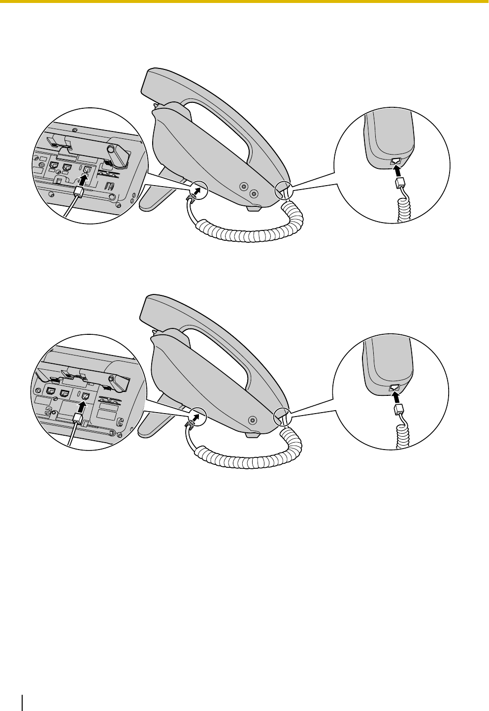
Connections for Handset
For KX-UT133/KX-UT136/KX-UT248:
For KX-UT113/KX-UT123:
62 Operating Instructions Document Version 2011-10
Installation and Setup
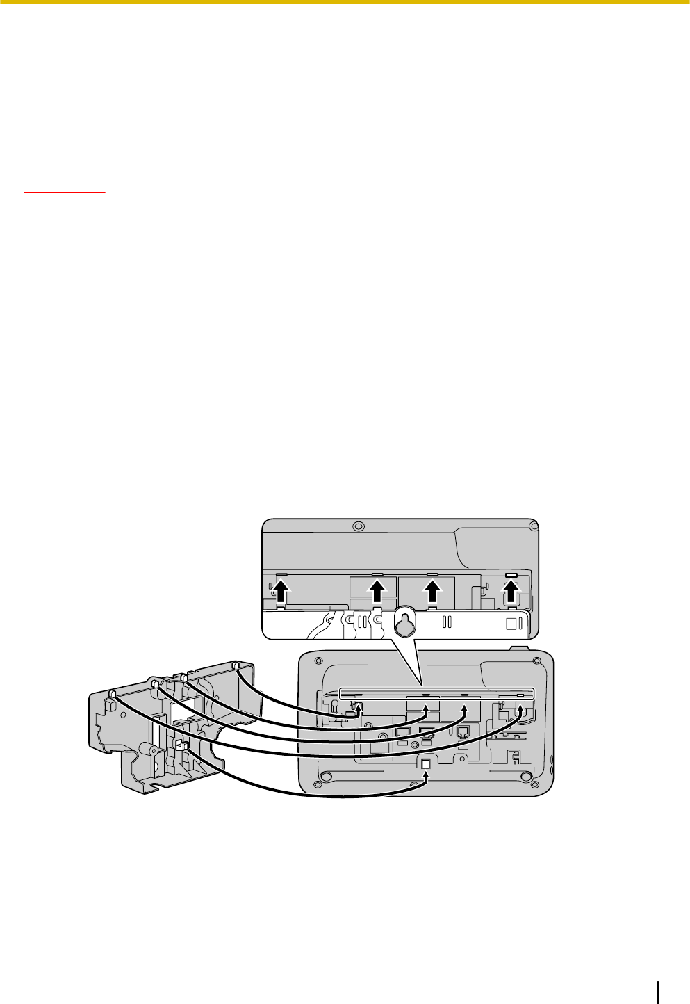
Wall Mounting
Before Mounting on a Wall
To mount the unit, it is necessary to remove the stand. For details, see "Removing the Stand (Page 57)".
Mounting the Unit
WARNING
•Do not mount the unit in a manner other than that described in this section.
•Make sure that the wall that the unit will be attached to is strong enough to support the unit. If not, it is
necessary for the wall to be reinforced. For information about the weight of the unit, see "Specifications
(Page 72)".
•Only use the optional wall mount kit with the unit. The wall mount kit includes the necessary screws,
washers, and wall mounting adaptor.
•When driving the screws into the wall, be careful to avoid touching any metal laths, wire laths or metal
plates in the wall.
•When this unit is no longer in use, make sure to detach it from the wall.
CAUTION
•Make sure the cables are securely fastened to the wall.
1. Insert the 5 tabs (for KX-UT133/KX-UT136/KX-UT248) or 3 tabs (for KX-UT113/KX-UT123) of the wall
mounting adaptor into the designated openings in the base, and then slide the wall mounting adaptor in
the direction of the arrow until it clicks.
For KX-UT133/KX-UT136/KX-UT248:
Document Version 2011-10 Operating Instructions 63
Installation and Setup
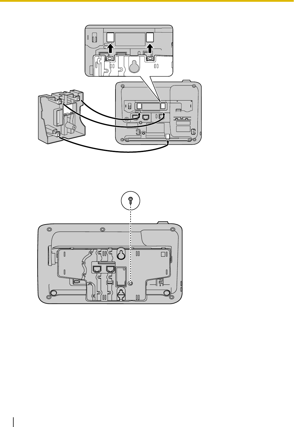
For KX-UT113/KX-UT123:
2. Fasten the wall mounting adaptor to the base with 1 screw. (Recommended torque: 0.4 N·m [4.08 kgf·cm/
3.54 lbf·in] to 0.6 N·m [6.12 kgf·cm/5.31 lbf·in])
For KX-UT133/KX-UT136/KX-UT248:
64 Operating Instructions Document Version 2011-10
Installation and Setup
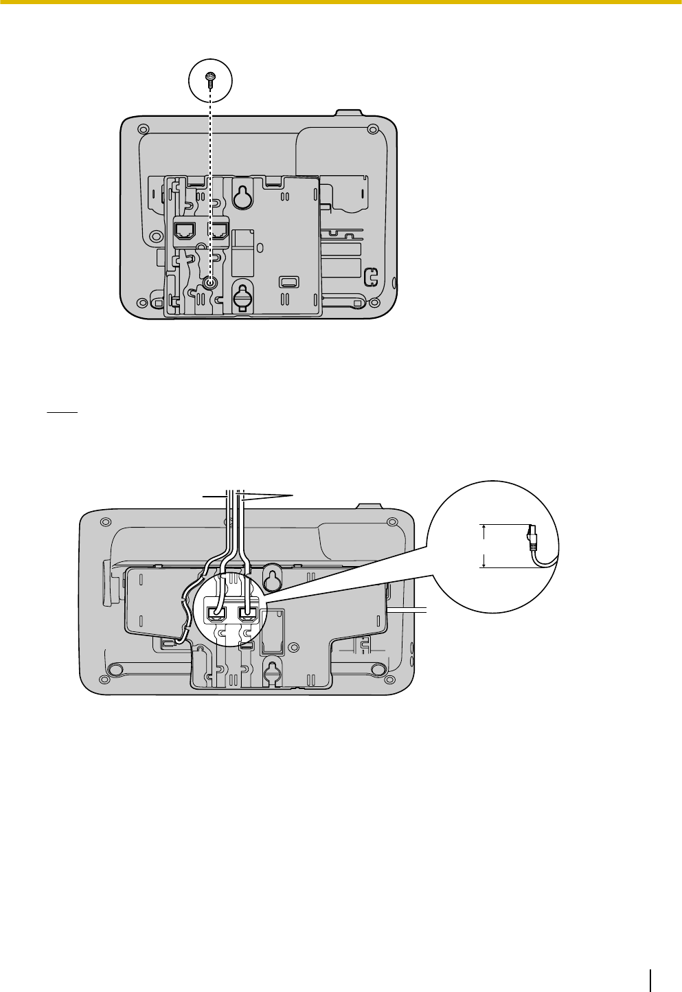
For KX-UT113/KX-UT123:
3. Connect the cables to the unit, and run the cables through the wall mounting adaptor, as shown in the
illustration below.
For details about connecting the cables, see "Connections (Page 60)".
Note
•The cables can also be run from the bottom of the unit.
For KX-UT133/KX-UT136/KX-UT248:
40 mm (1
37/64 in)
or less
Ethernet cables
AC adaptor
Document Version 2011-10 Operating Instructions 65
Installation and Setup
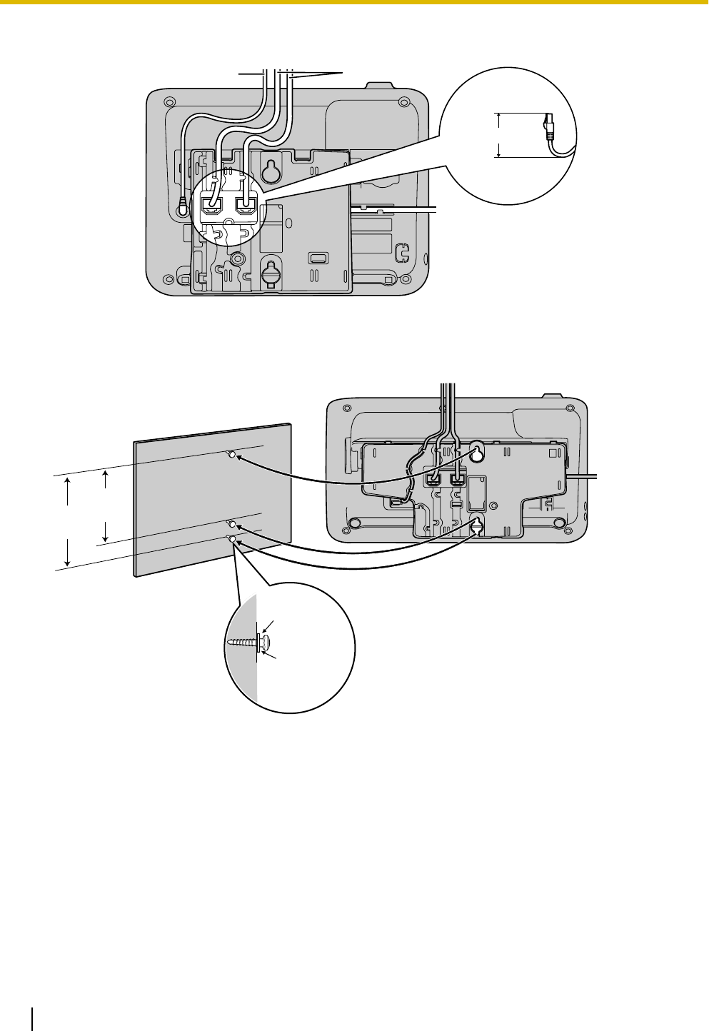
For KX-UT113/KX-UT123:
40 mm (1
37/64 in)
or less
Ethernet cables
AC adaptor
4. Drive 2 screws into the wall as shown in the illustration below, and mount the unit on the wall.
For KX-UT133/KX-UT136/KX-UT248:
83
mm
(3
1/4 in)
100
mm
(3
15/16 in)
Washer
Drive the screw
to this point.
66 Operating Instructions Document Version 2011-10
Installation and Setup
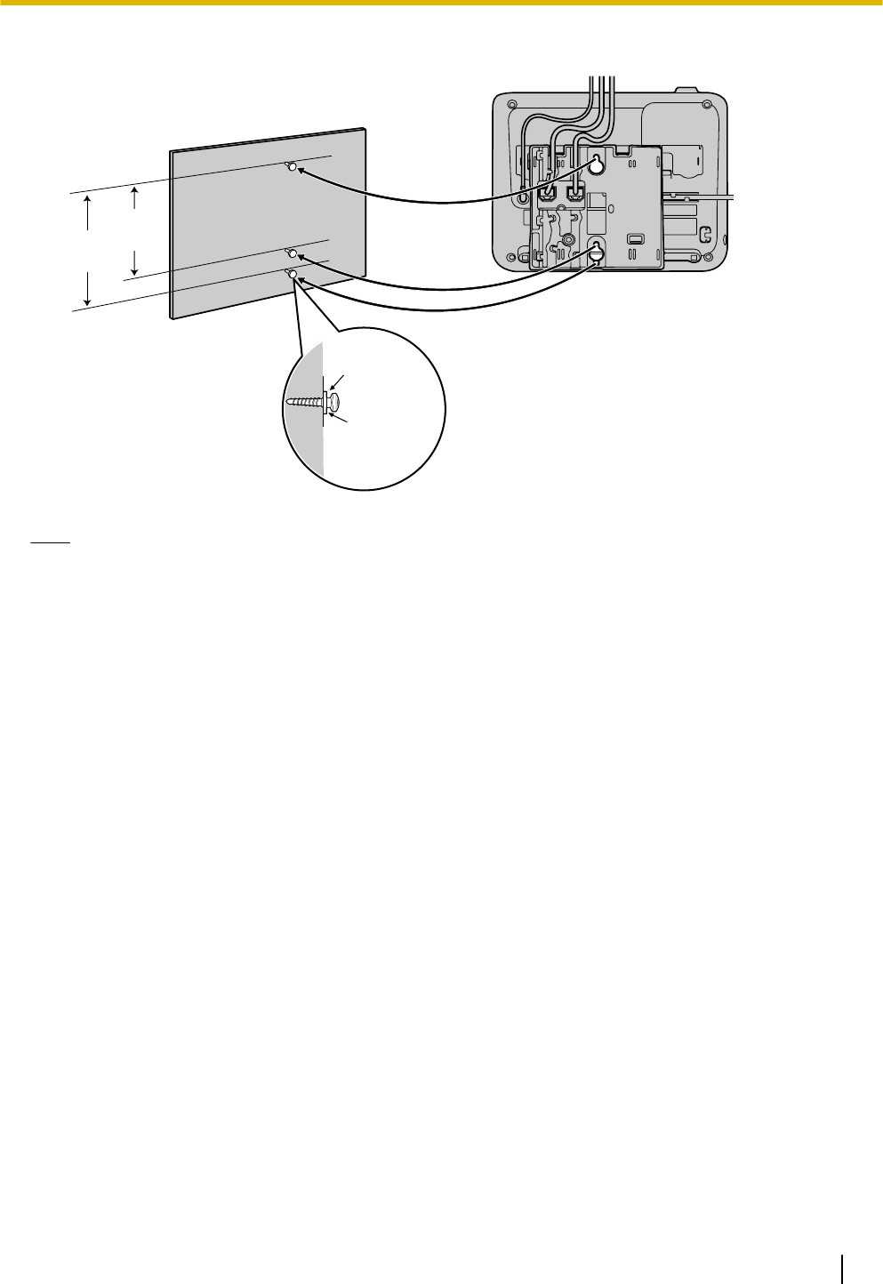
For KX-UT113/KX-UT123:
Washer
Drive the screw
to this point.
83
mm
(3
1/4 in)
100
mm
(3
15/16 in)
Note
•You can find a wall mounting template at the end of this manual.
•For information about locking the handset, see "Hooking the Handset (Page 68)".
Document Version 2011-10 Operating Instructions 67
Installation and Setup
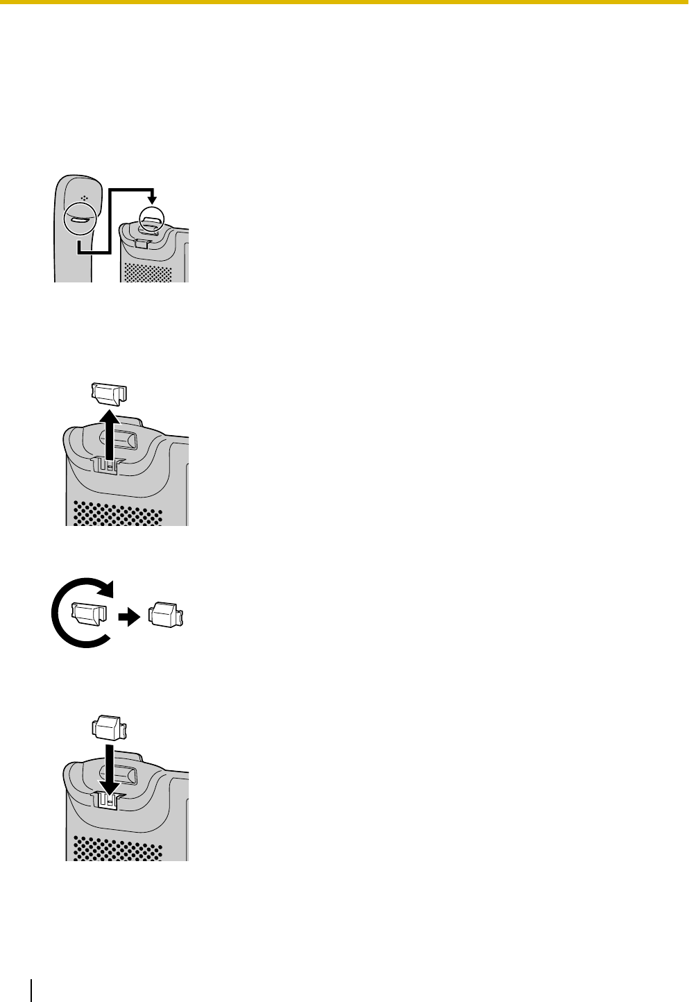
Hooking the Handset
You can hook the handset with following operations.
To Hook the Handset During a Conversation
1. Hook the handset over the top edge of the unit.
To Lock the Handset Hook when the Unit is Wall Mounted
1. Remove the handset hook from the slot.
2. Turn it up-side-down.
3. Slide the handset hook back into the slot until it locks.
68 Operating Instructions Document Version 2011-10
Installation and Setup

4. Handset is safely hooked when it is in the cradle.
Document Version 2011-10 Operating Instructions 69
Installation and Setup

Using a Headset
For KX-UT133/KX-UT136, if a headset is connected,
you must enable Headset mode using the Headset
button (flexible button).
To enable Headset mode, press the Headset button
(flexible button). When in Headset mode,
[SP-PHONE] is used for going on- and off-hook.
Making a Call Using a Headset
1. Press [SP-PHONE].
2. Enter the number you want to call.
3. Press [ENTER], or wait a few seconds for the
number to be dialed.
4. To end the call, press [SP-PHONE].
Receiving a Call Using a Headset
1. Press [SP-PHONE].
2. To end the call, press [SP-PHONE].
Note
•For details about connecting a headset, see
"Connections (Page 60)".
•For KX-UT113/KX-UT123, the Headset mode is
automatically enabled when connecting a
headset.
•The Headset button light shows the current
status as follows:
Off: Headset mode off
Red on: Headset mode on
•For details about setting a flexible button as the
Headset button, consult your administrator or
dealer.
Setting Up the Unit
This section explains the settings that you can configure
when you start the unit.
Accessing the start-up settings
1. Connect the unit to an Ethernet cable capable of
delivering power (PoE compliant), or use an
optional AC adaptor to supply power.
2. Connect the unit to the network.
3. On the start-up screen, press
Setup
.
4. Select the item for the settings you want to
configure.
Start-up menu
You can configure the following start-up settings:
1. Information Display (Page 43)
View a variety of information about the unit.
2. Network Settings (Page 43)
Assign an IP address in order to connect to the
network and use the unit.
3. Network Test (Page 45)
Confirm the connection of network devices (e.g.,
the SIP server, routers, switching hubs).
4. ECO Mode (Page 40)
Enable ECO mode.
5. Language (Page 42)
If you prefer to use a language other than English,
change your language settings.
6. Default Setting (Page 46)
Initialize the unit to reset the settings to their default
values.
7. Restart (Page 46)
Restart the unit for new settings to take effect.
8. Firmware version (Page 46)
Check the firmware version of the unit.
70 Operating Instructions Document Version 2011-10
Installation and Setup
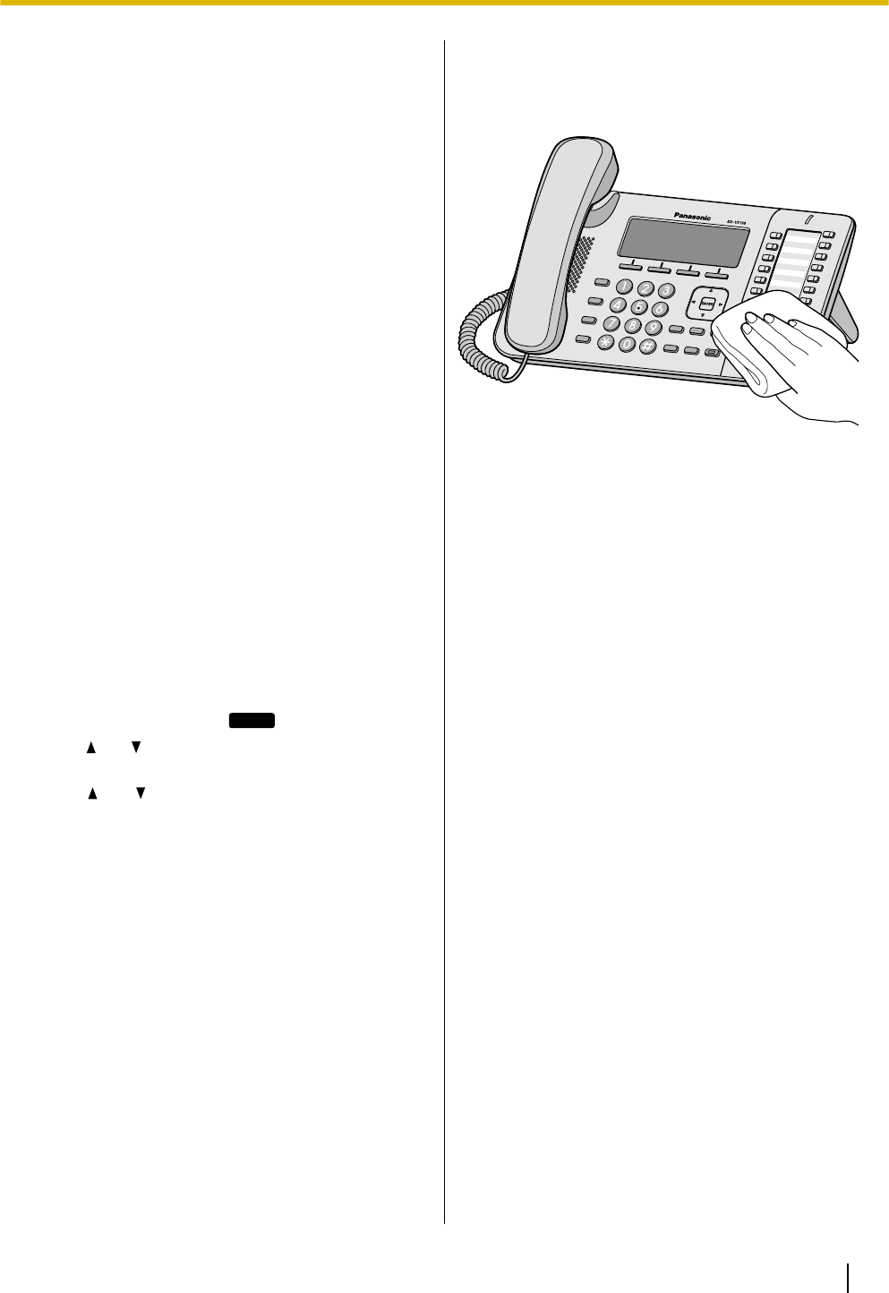
Maintaining the Unit
Initializing the Unit
Doing an initialization resets some or all settings to their
default values. There are two types of initialization:
•Factory Setting
Resets all settings in the unit to their default values.
This type of initialization also deletes all other data
on the unit, such as the call logs and the phonebook.
Do a Factory Setting initialization before
transferring the unit to a third party, such as for
maintenance. Doing so reduces the risk of an
unauthorized third party obtaining personal data.
•IP Reset
Resets only the network settings to their default
values.
Do an IP Reset initialization when changing the
unit's network environment.
For details about doing an initialization, see "Default
Setting (Page 46)".
Restarting the Unit
When some of the settings on the unit have been
changed via Web user interface programming or
configuration file programming, the unit must be
restarted.
1. In stand-by mode, press
Setting
.
2. Press [ ] or [ ] to select "Restart", and then press
[ENTER].
3. Press [ ] or [ ] to select "Yes", and then press
[ENTER].
•To cancel, select "No".
Cleaning the Unit
Clean the unit by periodically by wiping it with a soft and
dry cloth.
When cleaning the unit, observe the following
precautions.
When cleaning the display
•Wipe the display with only the following types of
materials:
–A soft and dry cloth.
–A soft cloth with very small quantity of neutral
detergent or ethyl alcohol.
•Do not press or rub the display with too much force.
When cleaning the body
•To avoid damaging the unit, disconnect the
Ethernet cable and all other cables from the unit
before cleaning. If the unit is powered with an AC
adaptor, disconnect the AC adaptor from the unit
and power outlet before cleaning.
•If the unit becomes particularly dirty, apply a light
kitchen cleanser to a soft cloth, wring the cloth
thoroughly, and then wipe the unit. When finished,
dry the unit with a soft and dry cloth.
•To avoid damage or discoloration, do not clean the
unit with the any of following materials or with
cleaners that contain any of the following materials:
–Petroleum
–Scouring powder
–Alcohol
–Paint thinner
–Benzene
–Wax
–Hot water
–Powdered soap
•When using chemical cleansers, follow the
instructions on the label carefully.
Document Version 2011-10 Operating Instructions 71
Installation and Setup
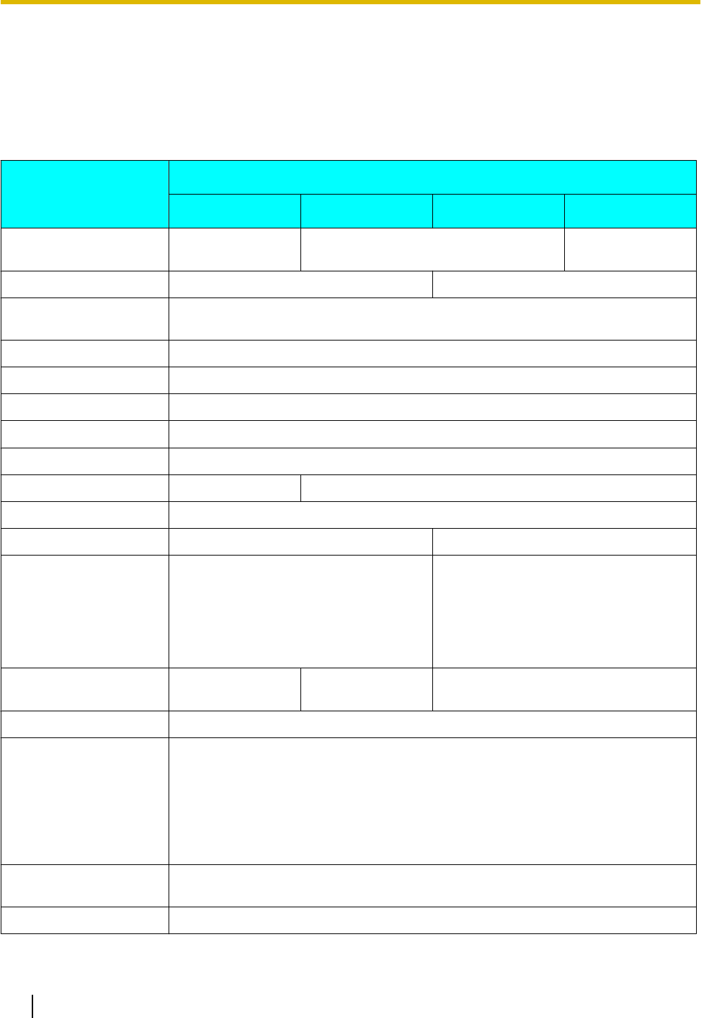
Appendix
Specifications
For KX-UT113/KX-UT123/KX-UT133/KX-UT136
Item
Specifications
KX-UT113 KX-UT123 KX-UT133 KX-UT136
Display 3 line (No
backlight) 3 line with backlight 6 line with
backlight
Flexible Buttons — 24
VoIP Connection
Method SIP
VoIP Audio Codec G.722, G.711, G.729A, G.726
Ethernet Interface 10Base-T/100Base-TX
IP Address Mode Automatic (DHCP), Manual (static)
Speaker 1
Microphone 1
Ethernet Port (LAN) 1 (RJ45) 2 (RJ45)
Headset Jack 1 (ø 2.5 mm [3/32 in])
EHS Jack — 1 (ø 3.5 mm [1/8 in], for EHS only)
Dimensions
(Width ´ Depth ´ Height;
handset on cradle, stand
attached)
205 mm ´ 160 mm ´ 170 mm
(8.07 in ´ 6.30 in ´ 6.69 in)
"High" position:
267 mm ´ 170 mm ´ 180 mm
(10.5 in ´ 6.69 in ´ 7.09 in)
"Low" position:
267 mm ´ 187 mm ´ 155 mm
(10.5 in ´ 7.36 in ´ 6.10 in)
Weight (with handset,
handset cord and stand) 860 g (1.90 lb) 870 g (1.92 lb) 1120 g (2.47 lb)
PoE IEEE 802.3af compliant
Power Consumption PoE
Stand-by: approx. 1.8 W (ECO mode off), approx. 1.3 W (ECO mode on)
Talking: approx. 2 W (ECO mode off), approx. 1.5 W (ECO mode on)
AC Adaptor
Stand-by: approx. 1.6 W (ECO mode off), approx. 1 W (ECO mode on)
Talking: approx. 2 W (ECO mode off), approx. 1.5 W (ECO mode on)
Maximum Power
Consumption 6 W
Operating Environment 0 °C to 40 °C (32 °F to 104 °F)
72 Operating Instructions Document Version 2011-10
Appendix

For KX-UT248
Item Specifications
Display 4.4 inch with backlight
Flexible Buttons 24
VoIP Connection
Method SIP
VoIP Audio Codec G.722, G.711, G.729A, G.726
Ethernet Interface 10Base-T/100Base-TX/1000Base-T
IP Address Mode Automatic (DHCP), Manual (static)
Speaker 1
Microphone 1
Ethernet Port (LAN) 2 (RJ45)
Headset Jack 1 (ø 2.5 mm [3/32 in])
EHS Jack 1 (ø 3.5 mm [1/8 in], for EHS only)
Bluetooth Bluetooth wireless technology 2.0
Dimensions
(Width ´ Depth ´ Height;
handset on cradle, stand
attached)
"High" position:
267 mm ´ 170 mm ´ 180 mm
(10.5 in ´ 6.69 in ´ 7.09 in)
"Low" position:
267 mm ´ 187 mm ´ 155 mm
(10.5 in ´ 7.36 in ´ 6.10 in)
Weight (with handset,
handset cord and stand) 1130 g (2.49 lb)
PoE IEEE 802.3af compliant
Power Consumption PoE
Stand-by: approx. 3.0 W (ECO mode off), approx. 1.3 W (ECO mode on)
Talking: approx. 4.6 W (ECO mode off), approx. 1.5 W (ECO mode on)
AC Adaptor
Stand-by: approx. 1.6 W (ECO mode off), approx. 1 W (ECO mode on)
Talking: approx. 2 W (ECO mode off), approx. 1.5 W (ECO mode on)
Maximum Power
Consumption 6.5 W
Operating Environment 0 °C to 40 °C (32 °F to 104 °F)
Document Version 2011-10 Operating Instructions 73
Appendix
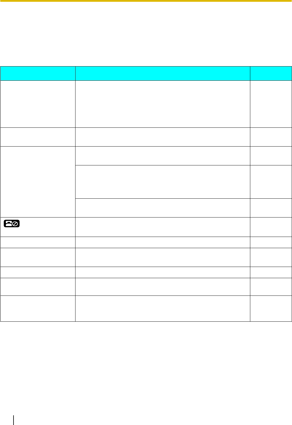
Troubleshooting
Common Issues and Solutions
General Use
Issue Possible Cause & Solution Reference
The display is blank. •The unit is not receiving power.
→The unit is not designed to function when there is a power
failure. Make sure that the device supplying PoE is
receiving power and that the Ethernet cable is properly
connected. If an AC adaptor is connected, confirm that the
AC adaptor is connected and receiving power.
Page 60
The display is not shown
well. •The display's contrast is too low.
→Adjust the display's contrast. Page 40
The unit is not performing
properly. •Cables or cords are not connected properly.
→Check all connections. Page 60
•Your connection settings are incorrect.
→Consult your administrator to confirm that your settings are
correct.
→If the problem persists, consult your dealer.
Page 37
•An error has occurred.
→Restart the unit. Page 71
is displayed on the
screen.
•Registration to the SIP server has been lost.
→Consult your administrator or dealer. —
I cannot hear a dial tone. •Confirm that the LAN cable is properly connected. Page 60
I cannot cancel the display
lock. •The PIN number you entered was incorrect.
→Consult your administrator or dealer. —
I forgot my PIN number. •Consult your administrator or dealer. —
The date and time are not
correct. •Adjust the date and time of the unit. Page 43
The Message/Ringer lamp
is lit. •You received a voice message while you were on the phone
or away from your desk.
→Check the voice message.
Page 32
74 Operating Instructions Document Version 2011-10
Appendix
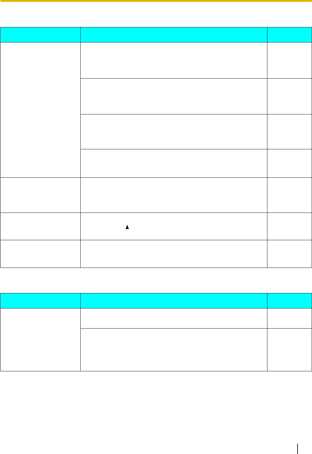
Making and Receiving Calls
Issue Possible Cause & Solution Reference
I cannot make calls. •Your phone system/service has disabled service for your unit.
→On the Information Display screen (Page 43), if "Not
registered" is displayed in "Status", consult your
administrator or dealer.
—
•The phone number was entered incorrectly.
→Confirm that you have entered the phone number of the
other party correctly.
→Consult your administrator or dealer.
Page 25
•The unit is downloading a firmware update.
→You cannot make calls while the unit is downloading
updates. Wait for the update to finish, and then try making
a call.
—
•The phonebook list is being imported or exported.
→Wait a few minutes for the operation to complete.
→Confirm with your administrator or dealer.
—
I cannot make long
distance calls. •Your telephone service does not allow you to make long
distance calls.
→Make sure that you have subscribed to your telephone
company’s long distance service.
—
The unit does not ring
when a call is received. •The ringer is turned off.
→Press [ ] while a call is being received, or change the
ringer volume setting.
Page 40
While talking to an outside
party, the line is
disconnected.
•Your phone system/service may impose a time limit on outside
calls.
→Consult your dealer to extend the time limit, if necessary.
—
Sound Quality
Issue Possible Cause & Solution Reference
The other party cannot
hear my voice. •The unit is muted.
→Press [MUTE] to turn off the mute feature. Page 30
•If you are using the speakerphone, objects may be obstructing
the microphone.
→Do not obstruct the unit's microphone during calls. Keep
your hands, as well as common objects such as folders,
cups, and coffee pots away from the unit during calls.
—
Document Version 2011-10 Operating Instructions 75
Appendix
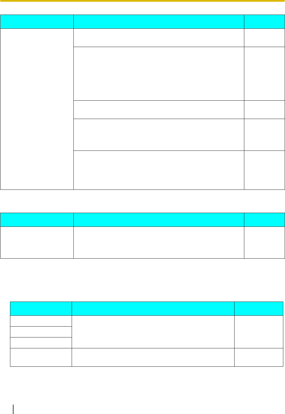
Issue Possible Cause & Solution Reference
Sound cuts out; I can hear
myself through the
speaker.
•You are too far away from the microphone.
→Try speaking closer to the microphone. —
•The environment is not suited to speakerphone calls.
→Do not use the unit within 2 m of projectors, air conditioning
devices, fans, or other audible or electrical noise emitting
devices.
→If using the unit in a room with windows, close the curtains
or blinds to prevent echoes.
→Use the unit in a quiet environment.
—
•The unit was moved during a call.
→Do not move the unit while on a call. —
•Objects are obstructing the microphone.
→Do not obstruct the unit during calls. Keep your hands, as
well as common objects such as folders, cups, and coffee
pots away from the unit during calls.
—
•The other party is using a half-duplex speakerphone.
→If the other party is using a half-duplex speakerphone,
sound may cut out occasionally during calls. For best
performance, the other party should use a full-duplex
speakerphone.
—
Phonebook List
Issue Possible Cause & Solution Reference
I cannot add or edit entries
to the phonebook list. •The phonebook list is full.
→Delete any unnecessary entries. The maximum number of
entries in the phonebook list is 500 for the KX-UT123/
KX-UT133/KX-UT136 and 100 for the KX-UT113.
Page 35
Error Messages
During operation, error messages might appear on the unit. The following table lists these messages and
possible causes and solutions.
Message Possible Causes & Solutions Reference
IP address collision •The unit’s network settings are incorrect.
→Consult your system administrator or dealer. —
Illegal IP address
Invalid IP address
Check LAN cable. •The LAN cable is not connected.
→Check all connections. Page 60
76 Operating Instructions Document Version 2011-10
Appendix

Message Possible Causes & Solutions Reference
Memory Full •A new entry for the phonebook or call block list cannot be
stored because the phonebook or call block list is full.
→Erase unneeded entries.
Page 36
No Entries •The phonebook or call block list contains no entries.
→Store entries in the phonebook or call block list.
Page 35
Page 27
Please wait… •The unit is still starting up.
→If you have a lot of entries in the phonebook list, the
unit may take a while to start up. This is normal.
—
Document Version 2011-10 Operating Instructions 77
Appendix

Open Source Software
Parts of this product use Open Source Software. Relevant conditions apply to this software. Panasonic cannot
accept inquiries regarding the content of the following copyright and license information.
<<NetBSD kernel>>
This product uses a part of NetBSD kernel.
The use of a part of NetBSD kernel is based on the typical BSD style
license below.
Copyright (c)
The Regents of the University of California. All rights reserved.
Redistribution and use in source and binary forms, with or without
modification, are permitted provided that the following conditions
are met:
1. Redistributions of source code must retain the above copyright
notice, this list of conditions and the following disclaimer.
2. Redistributions in binary form must reproduce the above copyright
notice, this list of conditions and the following disclaimer in the
documentation and/or other materials provided with the distribution.
3. All advertising materials mentioning features or use of this software
must display the following acknowledgement:
This product includes software developed by the University of
California, Berkeley and its contributors.
4. Neither the name of the University nor the names of its contributors
may be used to endorse or promote products derived from this software
without specific prior written permission.
THIS SOFTWARE IS PROVIDED BY THE REGENTS AND CONTRIBUTORS "AS IS'' AND
ANY EXPRESS OR IMPLIED WARRANTIES, INCLUDING, BUT NOT LIMITED TO, THE
IMPLIED WARRANTIES OF MERCHANTABILITY AND FITNESS FOR A PARTICULAR PURPOSE
ARE DISCLAIMED. IN NO EVENT SHALL THE REGENTS OR CONTRIBUTORS BE LIABLE
FOR ANY DIRECT, INDIRECT, INCIDENTAL, SPECIAL, EXEMPLARY, OR CONSEQUENTIAL
DAMAGES (INCLUDING, BUT NOT LIMITED TO, PROCUREMENT OF SUBSTITUTE GOODS
OR SERVICES; LOSS OF USE, DATA, OR PROFITS; OR BUSINESS INTERRUPTION)
HOWEVER CAUSED AND ON ANY THEORY OF LIABILITY, WHETHER IN CONTRACT, STRICT
LIABILITY, OR TORT (INCLUDING NEGLIGENCE OR OTHERWISE) ARISING IN ANY WAY
OUT OF THE USE OF THIS SOFTWARE, EVEN IF ADVISED OF THE POSSIBILITY OF
SUCH DAMAGE.
However, parts of the NetBSD Kernel are provided with the following copyright notices.
Copyright (c) 1980, 1983, 1988, 1993 The Regents of the University of California. All rights reserved.
Copyright (c) 1980, 1986, 1989, 1993 The Regents of the University of California. All rights reserved.
Copyright (c) 1980, 1986, 1991, 1993 The Regents of the University of California. All rights reserved.
Copyright (c) 1980, 1986, 1993 The Regents of the University of California. All rights reserved.
Copyright (c) 1982, 1985, 1986, 1988, 1993, 1994 The Regents of the University of California. All rights reserved.
Copyright (c) 1982, 1986, 1988, 1990, 1993 The Regents of the University of California. All rights reserved.
Copyright (c) 1982, 1986, 1988, 1990, 1993, 1994, 1995 The Regents of the University of California. All rights reserved.
Copyright (c) 1982, 1986, 1988, 1990, 1993, 1995 The Regents of the University of California. All rights reserved.
Copyright (c) 1982, 1986, 1988, 1991, 1993 The Regents of the University of California. All rights reserved.
Copyright (c) 1982, 1986, 1988, 1993 The Regents of the University of California. All rights reserved.
Copyright (c) 1982, 1986, 1988, 1993, 1995 The Regents of the University of California. All rights reserved.
Copyright (c) 1982, 1986, 1989, 1991, 1993 The Regents of the University of California. All rights reserved.
Copyright (c) 1982, 1986, 1989, 1993 The Regents of the University of California. All rights reserved.
Copyright (c) 1982, 1986, 1990, 1991, 1993 The Regents of the University of California. All rights reserved.
Copyright (c) 1982, 1986, 1990, 1993 The Regents of the University of California. All rights reserved.
Copyright (c) 1982, 1986, 1990, 1993, 1994 The Regents of the University of California. All rights reserved.
Copyright (c) 1982, 1986, 1991, 1993 The Regents of the University of California. All rights reserved.
Copyright (c) 1982, 1986, 1991, 1993, 1994 The Regents of the University of California. All rights reserved.
Copyright (c) 1982, 1986, 1991, 1993, 1995 The Regents of the University of California. All rights reserved.
Copyright (c) 1982, 1986, 1993 The Regents of the University of California. All rights reserved.
Copyright (c) 1982, 1986, 1993, 1994 The Regents of the University of California. All rights reserved.
Copyright (c) 1982, 1986, 1993, 1994, 1995 The Regents of the University of California. All rights reserved.
78 Operating Instructions Document Version 2011-10
Open Source Software

Copyright (c) 1982, 1986, 1993, 1995 The Regents of the University of California. All rights reserved.
Copyright (c) 1982, 1988, 1991, 1993 The Regents of the University of California. All rights reserved.
Copyright (c) 1983, 1990, 1993 The Regents of the University of California. All rights reserved.
Copyright (c) 1983, 1993 The Regents of the University of California. All rights reserved.
Copyright (c) 1985, 1986, 1993 The Regents of the University of California. All rights reserved.
Copyright (c) 1985, 1986, 1993 The Regents of the University of California. All rights reserved.
Copyright (c) 1986, 1989, 1991, 1993 The Regents of the University of California. All rights reserved.
Copyright (c) 1986, 1993 The Regents of the University of California. All rights reserved.
Copyright (c) 1987, 1991, 1993 The Regents of the University of California. All rights reserved.
Copyright (c) 1987, 1993 The Regents of the University of California. All rights reserved.
Copyright (c) 1987, 1993 The Regents of the University of California. All rights reserved.
Copyright (c) 1988 Regents of the University of California. All rights reserved
Copyright (c) 1988 Stephen Deering.
Copyright (c) 1988 University of Utah.
Copyright (c) 1988, 1989, 1993 The Regents of the University of California. All rights reserved.
Copyright (c) 1988, 1991, 1993 The Regents of the University of California. All rights reserved.
Copyright (c) 1988, 1992, 1993 The Regents of the University of California. All rights reserved.
Copyright (c) 1988, 1993 The Regents of the University of California. All rights reserved.
Copyright (c) 1989 The Regents of the University of California. All rights reserved.
Copyright (c) 1989, 1991, 1993 The Regents of the University of California. All rights reserved.
Copyright (c) 1989, 1993 The Regents of the University of California. All rights reserved.
Copyright (c) 1989, 1993, 1994 The Regents of the University of California. All rights reserved.
Copyright (c) 1990, 1991, 1993 The Regents of the University of California. All rights reserved.
Copyright (c) 1990, 1993 The Regents of the University of California. All rights reserved.
Copyright (c) 1991, 1993 The Regents of the University of California. All rights reserved.
Copyright (c) 1991, 1993, 1994 The Regents of the University of California. All rights reserved.
Copyright (c) 1992 Regents of the University of California. All rights reserved.
Copyright (c) 1992, 1993 The Regents of the University of California. All rights reserved.
Copyright (c) 1993 The Regents of the University of California. All rights reserved.
Copyright (c) 1993 Adam Glass
Copyright (C) 1993 by Sun Microsystems, Inc. All rights reserved.
Copyright (c) 1994 Gordon W. Ross
Copyright (c) 1994 Winning Strategies, Inc. All rights reserved.
Copyright (c) 1995 The Regents of the University of California. All rights reserved.
Copyright (C) 1995, 1996, 1997, and 1998 WIDE Project. All rights reserved.
Copyright (c) 1996 The Regents of the University of California. All rights reserved.
Copyright (c) 1996 John S. Dyson All rights reserved.
Copyright (c) 1996 Matt Thomas. All rights reserved.
Copyright (c) 1996 Matthew R. Green. All rights reserved.
Copyright (c) 1996 Paul Kranenburg
Copyright (c) 1996, 1997, 1999, 2001 The NetBSD Foundation, Inc. All rights reserved.
Copyright (c) 1996, 2000 Christopher G. Demetriou. All rights reserved.
Copyright (c) 1996,1999 by Internet Software Consortium.
Copyright (c) 1996-1999 by Internet Software Consortium.
Copyright (c) 1997 Jonathan Stone and Jason R. Thorpe. All rights reserved.
Copyright (c) 1997 Christos Zoulas. All rights reserved.
Copyright (c) 1997 Manuel Bouyer. All rights reserved.
Copyright (c) 1997, 1998 The NetBSD Foundation, Inc. All rights reserved.
Copyright (c) 1997, 1998, 1999, 2000 The NetBSD Foundation, Inc. All rights reserved.
Copyright (c) 1997, 1998, 1999, 2001 The NetBSD Foundation, Inc. All rights reserved.
Copyright (c) 1997, 1998, 1999, 2002 The NetBSD Foundation, Inc. All rights reserved.
Copyright (c) 1997, 1998, 2000, 2001 The NetBSD Foundation, Inc. All rights reserved.
Copyright (c) 1997, 1998, 2001 The NetBSD Foundation, Inc. All rights reserved.
Copyright (c) 1997,98 The NetBSD Foundation, Inc. All rights reserved.
Copyright (C) 1997-2000 Sony Computer Science Laboratories Inc. All rights reserved.
Copyright (c) 1997-2002 The NetBSD Foundation, Inc. All rights reserved.
Copyright (c) 1998 The NetBSD Foundation, Inc. All rights reserved.
Copyright (c) 1998 Todd C. Miller <Todd.Miller@courtesan.com> All rights reserved.
Copyright (c) 1998, 1999 The NetBSD Foundation, Inc. All rights reserved.
Copyright (c) 1998, 1999, 2000 The NetBSD Foundation, Inc. All rights reserved.
Copyright (c) 1998, 1999, 2000, 2001 The NetBSD Foundation, Inc. All rights reserved.
Copyright (c) 1998, 2000 The NetBSD Foundation, Inc. All rights reserved.
Copyright (c) 1998, 2000, 2001 The NetBSD Foundation, Inc. All rights reserved.
Copyright (c) 1999 The NetBSD Foundation, Inc. All rights reserved.
Copyright (C) 1999 WIDE Project. All rights reserved.
Document Version 2011-10 Operating Instructions 79
Open Source Software

Copyright (c) 1999, 2000 Jason L. Wright (jason@thought.net) All rights reserved.
Copyright (c) 1999, 2000 The NetBSD Foundation, Inc. All rights reserved.
Copyright (c) 1999, 2000, 2001 The NetBSD Foundation, Inc. All rights reserved.
Copyright (c) 1999, 2001 The NetBSD Foundation, Inc. All rights reserved.
Copyright (c) 2000 The NetBSD Foundation, Inc. All rights reserved.
Copyright (c) 2000, 2001 The NetBSD Foundation, Inc. All rights reserved.
Copyright (c) 2000, 2001, 2002 The NetBSD Foundation, Inc. All rights reserved.
Copyright (c) 2001 The NetBSD Foundation, Inc. All rights reserved.
Copyright (c) 2002 The NetBSD Foundation, Inc. All rights reserved.
Copyright 1998 Massachusetts Institute of Technology. All rights reserved.
Copyright 2001 Wasabi Systems, Inc. All rights reserved.
Portions Copyright (c) 1993 by Digital Equipment Corporation.
Portions Copyright (c) 1995 by International Business Machines, Inc.
Copyright (c) 1983, 1989 The Regents of the University of California. All rights reserved.
Copyright (c) 1996 by Internet Software Consortium. All rights reserved.
Copyright (c) 1980, 1986, 1989 Regents of the University of California. All rights reserved.
Copyright (c) 1988 The Regents of the University of California. All rights reserved.
Copyright (c) 1992, 1993 The Regents of the University of California. All rights reserved.
Copyright (c) 1994 Christopher G. Demetriou. All rights reserved.
Copyright (c) 1997 The NetBSD Foundation, Inc. All rights reserved.
Copyright (c) 1999 The NetBSD Foundation, Inc. All rights reserved.
Copyright (c) 2001 The NetBSD Foundation, Inc. All rights reserved.
Copyright (c) 1996 Gardner Buchanan <gbuchanan@shl.com> All rights reserved.
Parts of the NetBSD Kernel are provided with the licenses that are slightly different from the
above Berkeley-formed license. Please refer the source code of the NetBSD Kernel about the details.
The source code of the NetBSD Kernel is provided by the NetBSD CVS Repositories
(http://cvsweb.netbsd.org/bsdweb.cgi/), and this product includes parts of the source code in the
following directories.
http://cvsweb.netbsd.org/bsdweb.cgi/src/sys/kern/
http://cvsweb.netbsd.org/bsdweb.cgi/src/sys/net/
http://cvsweb.netbsd.org/bsdweb.cgi/src/sys/netinet/
<<MD5>>
This software uses the Source Code of RSA Data Security, Inc. described in the
RFC1321 (MD5 Message-Digest Algorithm).
-----------------------------------------------------------------
Copyright (C) 1991-2, RSA Data Security, Inc. Created 1991. All
rights reserved.
License to copy and use this software is granted provided that it
is identified as the "RSA Data Security, Inc. MD5 Message-Digest
Algorithm" in all material mentioning or referencing this software
or this function.
License is also granted to make and use derivative works provided
that such works are identified as "derived from the RSA Data
Security, Inc. MD5 Message-Digest Algorithm" in all material
mentioning or referencing the derived work.
RSA Data Security, Inc. makes no representations concerning either
the merchantability of this software or the suitability of this
software for any particular purpose. It is provided "as is"
without express or implied warranty of any kind.
These notices must be retained in any copies of any part of this
documentation and/or software.
-----------------------------------------------------------------
<<MT19937>>
The MT19937 software that Takuji Nishimura and Makoto Matsumoto developed
is contained, and this product shall be used subject to the following
license conditions.
Copyright (C) 1997 - 2002, Makoto Matsumoto and Takuji Nishimura,
All rights reserved.
Redistribution and use in source and binary forms, with or without
modification, are permitted provided that the following conditions
are met:
80 Operating Instructions Document Version 2011-10
Open Source Software

1. Redistributions of source code must retain the above copyright
notice, this list of conditions and the following disclaimer.
2. Redistributions in binary form must reproduce the above copyright
notice, this list of conditions and the following disclaimer in the
documentation and/or other materials provided with the distribution.
3. The names of its contributors may not be used to endorse or promote
products derived from this software without specific prior written
permission.
THIS SOFTWARE IS PROVIDED BY THE COPYRIGHT HOLDERS AND CONTRIBUTORS
"AS IS" AND ANY EXPRESS OR IMPLIED WARRANTIES, INCLUDING, BUT NOT
LIMITED TO, THE IMPLIED WARRANTIES OF MERCHANTABILITY AND FITNESS FOR
A PARTICULAR PURPOSE ARE DISCLAIMED. IN NO EVENT SHALL THE COPYRIGHT OWNER OR
CONTRIBUTORS BE LIABLE FOR ANY DIRECT, INDIRECT, INCIDENTAL, SPECIAL,
EXEMPLARY, OR CONSEQUENTIAL DAMAGES (INCLUDING, BUT NOT LIMITED TO,
PROCUREMENT OF SUBSTITUTE GOODS OR SERVICES; LOSS OF USE, DATA, OR
PROFITS; OR BUSINESS INTERRUPTION) HOWEVER CAUSED AND ON ANY THEORY OF
LIABILITY, WHETHER IN CONTRACT, STRICT LIABILITY, OR TORT (INCLUDING
NEGLIGENCE OR OTHERWISE) ARISING IN ANY WAY OUT OF THE USE OF THIS
SOFTWARE, EVEN IF ADVISED OF THE POSSIBILITY OF SUCH DAMAGE.
<<thttpd>>
The thttpd software that ACME Labs developed is contained, and this product
shall be used subject to the following license conditions.
Copyright 1995,1998,1999,2000 by Jef Poskanzer <jef@acme.com>.
All rights reserved.
Redistribution and use in source and binary forms, with or without
modification, are permitted provided that the following conditions
are met:
1. Redistributions of source code must retain the above copyright
notice, this list of conditions and the following disclaimer.
2. Redistributions in binary form must reproduce the above copyright
notice, this list of conditions and the following disclaimer in the
documentation and/or other materials provided with the distribution.
THIS SOFTWARE IS PROVIDED BY THE AUTHOR AND CONTRIBUTORS "AS IS'' AND
ANY EXPRESS OR IMPLIED WARRANTIES, INCLUDING, BUT NOT LIMITED TO, THE
IMPLIED WARRANTIES OF MERCHANTABILITY AND FITNESS FOR A PARTICULAR PURPOSE
ARE DISCLAIMED. IN NO EVENT SHALL THE AUTHOR OR CONTRIBUTORS BE LIABLE
FOR ANY DIRECT, INDIRECT, INCIDENTAL, SPECIAL, EXEMPLARY, OR CONSEQUENTIAL
DAMAGES (INCLUDING, BUT NOT LIMITED TO, PROCUREMENT OF SUBSTITUTE GOODS
OR SERVICES; LOSS OF USE, DATA, OR PROFITS; OR BUSINESS INTERRUPTION)
HOWEVER CAUSED AND ON ANY THEORY OF LIABILITY, WHETHER IN CONTRACT, STRICT
LIABILITY, OR TORT (INCLUDING NEGLIGENCE OR OTHERWISE) ARISING IN ANY WAY
OUT OF THE USE OF THIS SOFTWARE, EVEN IF ADVISED OF THE POSSIBILITY OF
SUCH DAMAGE.
Document Version 2011-10 Operating Instructions 81
Open Source Software

Index
A
AC adaptor 13
Connection 60
Accessories 13
ACD flexible button 34
ACD Group 33
Auto answer 27
AUTO ANSWER/MUTE button 16
Automatic Call Distribution ® ACD 33
B
Back Light (setting) 41
BLF flexible button 34
Busy Lamp Field ® BLF 34
C
Call Block (setting) 47
Call Forwarding 33
Call Splitting 29
Call Transfer 30
Call Waiting 29
Calls
From call logs 25
From phonebook list 25
Holding 28
Making 25
Missed 32
Receiving 27
Redialing 26
Rejecting 27
CANCEL button 16
Character entry 48
Cleaning 71
CONF (Conference) button 16
CONFERENCE button 16
Conference call 31
Connections 60
Controls 14
Bottom view 18
Front View 14
Left view 17
D
Date and Time (setting) 43
DC jack 18
Default Gateway (setting) 44
Dialing 25
Directory Number ® DN 34
Display 15
Contrast 40
Display Lock (setting) 41
DN flexible button 34
DNS (setting) 44
DNS1 (setting) 44
DNS2 (setting) 44
Do Not Disturb 33
Do Not Disturb (setting) 41
E
ECO Mode (setting) 40
EHS headsets 61
EHS jack 17
Electronic Hook Switch ® EHS 61
Embedded web (setting) 45
Enable VLAN (setting) 44
ENTER key 16
Error messages 76
Extension number 23
F
Factory Setting (setting) 46
Firmware version (setting) 46
FLASH/RECALL button 16
Flexible buttons 16, 34
FORWARD/DO NOT DISTURB button 16
Forwarding 33
FWD All (setting) 41
FWD Busy (setting) 41
FWD No Ans (setting) 42
G
Group, Login/Logout 33
H
Handset 13
Connections 62
Hooking 68
Volume 24
Handset cord 13
Handset hook 16
Handset jack 19
Hands-free mode 23
Headset 61
Flexible button 34
Using 70
Volume 24
HEADSET button 16
Headset jack 17
Hold 28
HOLD button 16
I
Information Display (setting) 43
Initialize 71
Installation 57
IP Address (setting) 44
IP Phone (setting) 44
IP Reset (setting) 46
L
LAN connection 60
LAN port 19
LAN port (setting) 45
Language (setting) 42
82 Operating Instructions Document Version 2011-10
Index

Last Number Redial 26
LCD (Liquid Crystal Display) 15
LCD Contrast (setting) 40
Local Three-way Conference 31
Login (to a Group) 33
Logout (from a Group) 33
M
Maintenance 71
Making calls 25
Calling 25
MESSAGE button 16
Message/Ringer Lamp 16
Messages, checking 32
MIC 16
Missed calls 32
MUTE/AUTO ANSWER button 16
N
Navigator key 16
Network (setting) 44
Network Test (setting) 45
O
Off-hook monitor 23
One-touch dialing 26
One-Touch flexible button 34
One-touch Transfer 30
P
Page keys 16
PC (setting) 45
PC connection 60
PC port 19
PC port (setting) 45
Phonebook list
Adding 35
Deleting 36
Editing 35
Export 36
Import 36
Searching 25, 36
Priority (setting) 45
Programming, web user interface 56
R
Receiving calls 27
Redial 26
REDIAL button 16
Rejecting calls 27
Restart 71
Restart (setting) 46
Ring count (setting) 42
Ringer
Volume setting 23
Ringer (setting) 40
Ringer Volume (setting) 40
Ringer/Message Lamp 16
Ringtone (setting) 40
S
Scroll indicator 20
Search, phonebook list 25
Settings 37
Accessing 37
Setup 57
Initial settings 70
Soft buttons 16, 21
icons 20
Icons 21
Speaker
Volume 24
Speakerphone (SP-PHONE) button 16
Specifications 72
Speed/Duplex (setting) 45
SP-PHONE (Speakerphone) button 16
Stand 13
Adjusting 58
Attaching 57
Removing 57
Start-up menu 70
Status icons 20
Subnet mask (setting) 44
T
Three-way conference 31
Transfer 30
TRANSFER button 16
Troubleshooting 74
U
User settings 37
V
VLAN (setting) 44
VLAN ID (setting) 45
Volume 23
W
Wall mount kit 13
Wall mounting 63
Web user interface programming 56
Document Version 2011-10 Operating Instructions 83
Index
83 mm (3
1
/
4 in)
100 mm (3
15
/
16 in)
for base unit
One screw here
One screw at either point
WALL MOUNTING TEMPLATE
1. Drive the screws into the wall as indicated.
2. Hook the unit onto the screw heads.
Note:
Make sure to set the print size to
correspond with the size of this page. If the
dimensions of the paper output still deviate
slightly from the measurements indicated
here, use the measurements indicated
here.

Document Version 2011-10 Operating Instructions 85
Notes

Copyright:
Panasonic System Networks Co., Ltd. 2011
This material is copyrighted by Panasonic System Networks Co., Ltd., and may be reproduced for internal
use only. All other reproduction, in whole or in part, is prohibited without the written consent of Panasonic
System Networks Co., Ltd.
PNQX3571XA DD0611MK2121 (v0.002)
One Panasonic Way, Secaucus, New Jersey 07094
http://www.panasonic.com/sip
5770 Ambler Drive, Mississauga, Ontario, L4W 2T3
http://www.panasonic.ca