Panasonic of North America 9TAK-SRC14 1.9 GHz Wireless Receiver User Manual
Panasonic Corporation of North America 1.9 GHz Wireless Receiver Users Manual
UserManual.wiki
>
Panasonic of North America
>
9TAK SRC14 User Manual
Users Manual
Navigation menu
Upload a User Manual
Namespaces
Wiki Guide
HTML
PDF
Info
Views
User Manual
Discussion / Help
Navigation
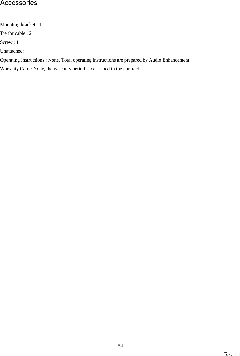
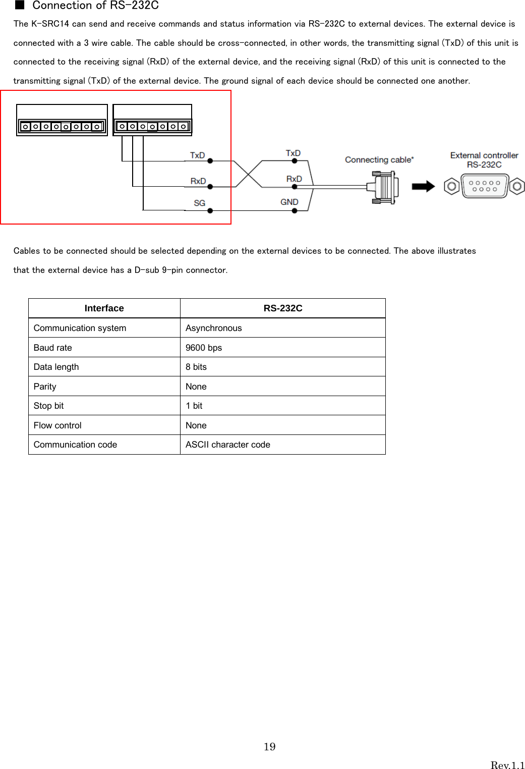
![6 Rev.1.1 Major operating controls and their functions [1][LINK] button Pressing this button will becomes register mode with a microphone. (Linkup connection is established or progress of 20 seconds will cancel this mode.) Refer to Operating procedures. [2] POWER indicator [POWER] (Green/Yellow/Red) This LED lights green when the power is on and this unit is receivable under normal conditions. This LED lights as follows to indicate other states: E2 signal output provided: lighting red (Lighting green at Power OFF) Page mute signal received: lighting yellow [3]MIC1/MIC2 indicator [MIC1/MIC2] This LED lights green when this unit is receiving signals from each microphone under normal conditions. This LED lights as follows to indicate other states: E2 signal output provided: lighting red. (Lighting green at E2 ACK input provided) Page mute signal received: lighting yellow E1 signal output provided: lighting (300ms) red Feedback blocker in operation: lighting(5sec) yellow [4] LINK indicator [LINK] This LED lights yellow(500ms) when this unit is during ID registration(Pairing) This LED lights red when this unit is system error 4 1 2 3 3 9 8 7 6 5](https://usermanual.wiki/Panasonic-of-North-America/9TAK-SRC14/User-Guide-2471606-Page-6.png)
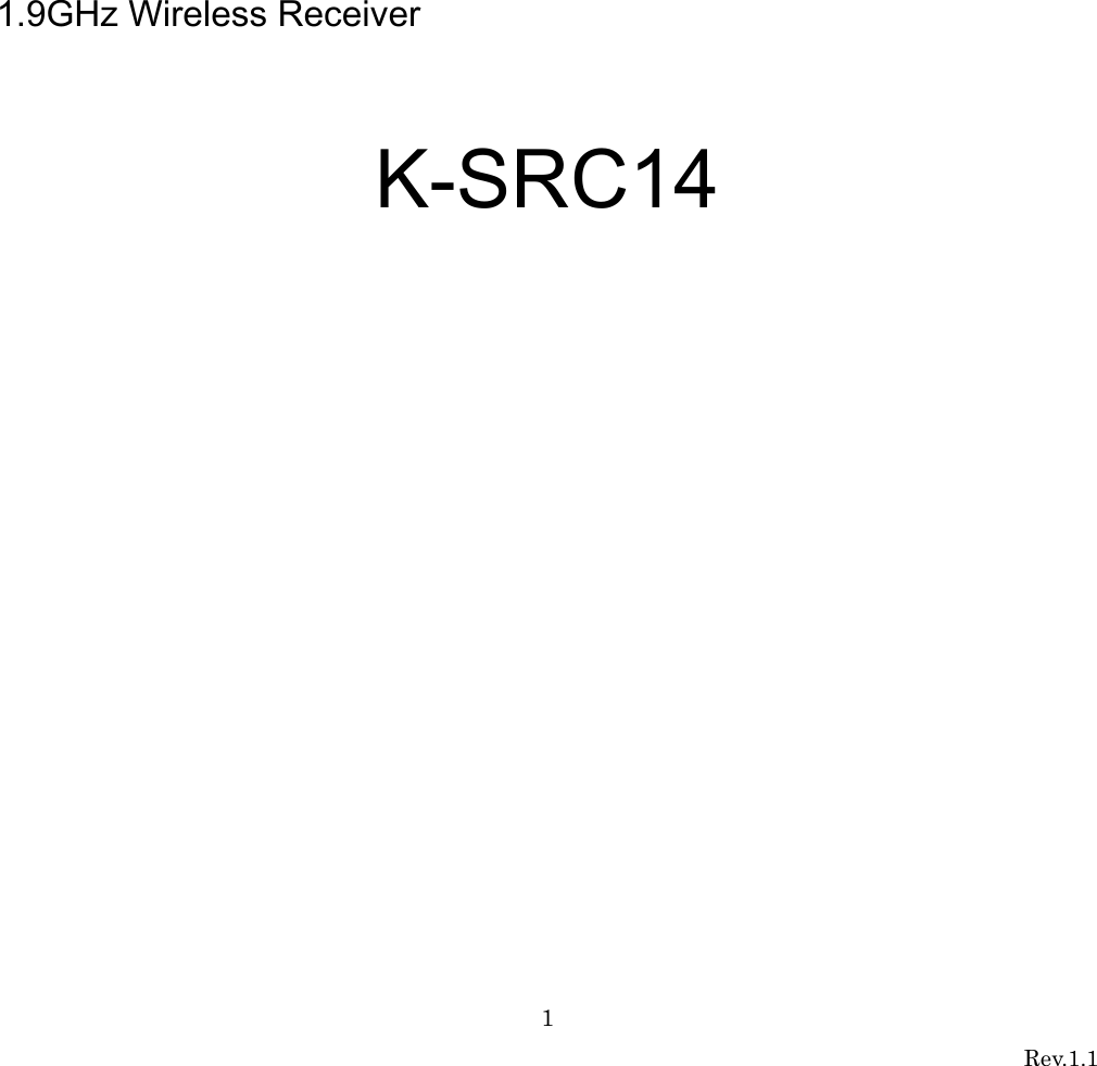
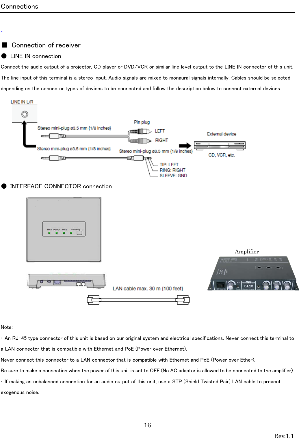
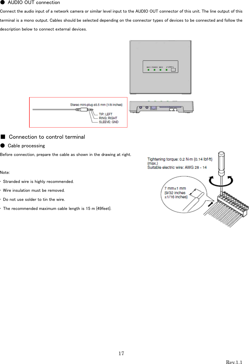
![7 Rev.1.1 [5]Control terminals 8-pin and 7-pin Euro blocks are used. The following terminals are equipped. E1 CNT: provides E1 signal * output controlled by K-STD14. E2 CNT: provides E2 signal * output controlled by K-STD14. * Those are available when K-STD14 is used. Settings of E1 and E2 are performed with K-STD14. E2 ACK: connects acknowledge signals responding to E2 output. PAGE MUTE: provides make signal inputs externally when the paging function is used. RS-232C: is used to control this unit via communication from an external device. LINK button: provides make signal inputs externally when the external link button is used. Alert notification button; provides make signal inputs externally when the external Alert notification button is used. [6] Amplifier interface connector This connector is used to connect the cable to the amplifier. A standard CAT5 or CAT5e cable is used to connect to the amplifier. [7] MIX OUT (unbalanced) connector This connector provides the audio output of LINE IN of the main unit. Setting the No. 4 of the DIP switch1 to ON allows the audio outputs of the microphone CH1 and CH2 received by this unit to be provided after mixing with LINE IN. This is an unbalanced output. A stereo mini plug (φ3.5 mm) is used. [8] LINE IN connector This connector is used to provide an audio input from external sources such as a projector or CD. This is a stereo, line level input, and is internally mixed to a monaural signal. A stereo mini plug (φ3.5 mm) is used. [9]DIP Switches Two DIP switches are used. The settings of this switch are updated at the time of turning on the power. Settings changed while powered up are not updated until the power is turned off and then back on. (Excluding No.7 of DIP Switch 1)](https://usermanual.wiki/Panasonic-of-North-America/9TAK-SRC14/User-Guide-2471606-Page-7.png)
![8 Rev.1.1 Operating procedures 1. A standard CAT5 or CAT5e cable is used to connect to the amplifier,. After that, turned on amplifier. The POWER LED of the receiver lights green. 2. Power ON of the microphone . [K-STD14] : Turn on the [PWR/MUTE] button. [K-SHH14] : Turn on the [PWR LINK] button. And Push [TALK push]button. The MIC1 or MIC2 LED indicator of the lights green ( depending on a channel to be received.) 3 .Adjust the volume of external devices such as an amplifier. The overall volume is adjusted with the external amplifier or the like. Use of the volume button of K-STD14 allows the volume of itself to be adjusted. In addition, selection of the target with the selection button of K-STD14 allows the volume of the other microphone received by this unit and the volume of LINE IN of this unit to be adjusted. 4. The LED of the POWER/MIC1/MIC2 indicates the operating state of this unit during operation. LED POWER indicator MIC1/MIC2 indicator E2 signal output provided* Lighting red Lighting red (lighting green at E2 ACK input provided) E1 signal output provided* Lighting green Lighting red (for 300 ms) Page mute signal input provided Lighting yellow Lighting yellow Microphone volume operated* Lighting green No lighting (for 300 ms) Feedback blocker operated Lighting green Lighting yellow (for 5 s) Audio link establishment Lighting green Lighting green * Applicable when K-STD14 is used 5. The LED of the LINK indicates the operating state of this unit during operation.](https://usermanual.wiki/Panasonic-of-North-America/9TAK-SRC14/User-Guide-2471606-Page-8.png)
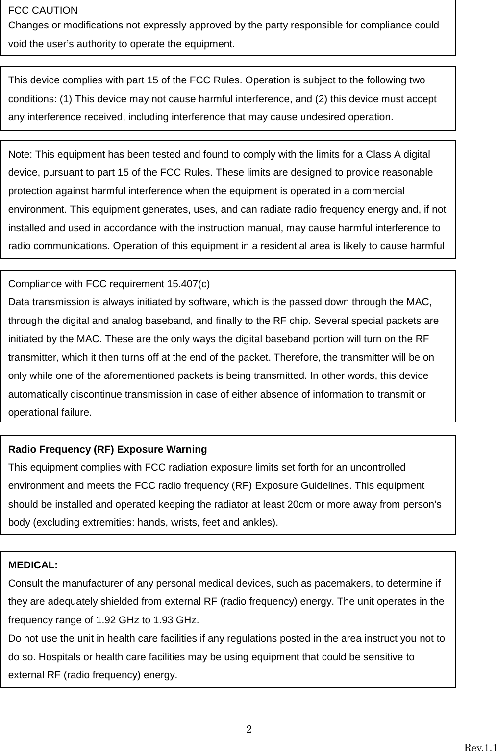
![10 Rev.1.1 Connection registration of the microphone to a receiver When connecting it with the receiver which has not connected once, pairing registration is needed first. Please perform pairing registration according to the following procedure. (Only the alert operates without registration work.) 1. Press a receiver's [LINK] button, and a receiver is made into register mode . 2. (a) Pendant microphone: Press [PWR/MUTE] button and [REC] button will register for receiver. Pendant microphone [BATT] indicator is green light. (b)Handheld microphone: Microphone LINK switch (inside the battery cover) is ON. (Different receiver connection) (Please read the operating instructions of the Handheld Microphone (K-SHH14).) Press [PWR LINK] button will register for receiver. Handheld microphone [BATT] indicator is blinking ( green ). A pairing setup is required first. 1. [LINK] button [PWR LINK] button [PWR/MUTE] button](https://usermanual.wiki/Panasonic-of-North-America/9TAK-SRC14/User-Guide-2471606-Page-10.png)
![11 Rev.1.1 Classroom Audio Pendant Microphone [K-STD14] 1. Press [PWR/MUTE] button will start a microphone. A microphone can be used in a classroom. (MIC1 or MIC2 LED indicator lighting green) Note: • Also read the operating instructions of the Pendant Microphone (K-STD14). Handheld Microphone [K-SHH14] 1. Press [PWR LINK] button will start a microphone. 2. Press [TALK push] button will start a microphone. A microphone can be used in a classroom. (MIC2 or MIC1 LED indicator lighting green) Note: • Also read the operating instructions of the Handheld Microphone (K-SHH14).](https://usermanual.wiki/Panasonic-of-North-America/9TAK-SRC14/User-Guide-2471606-Page-11.png)
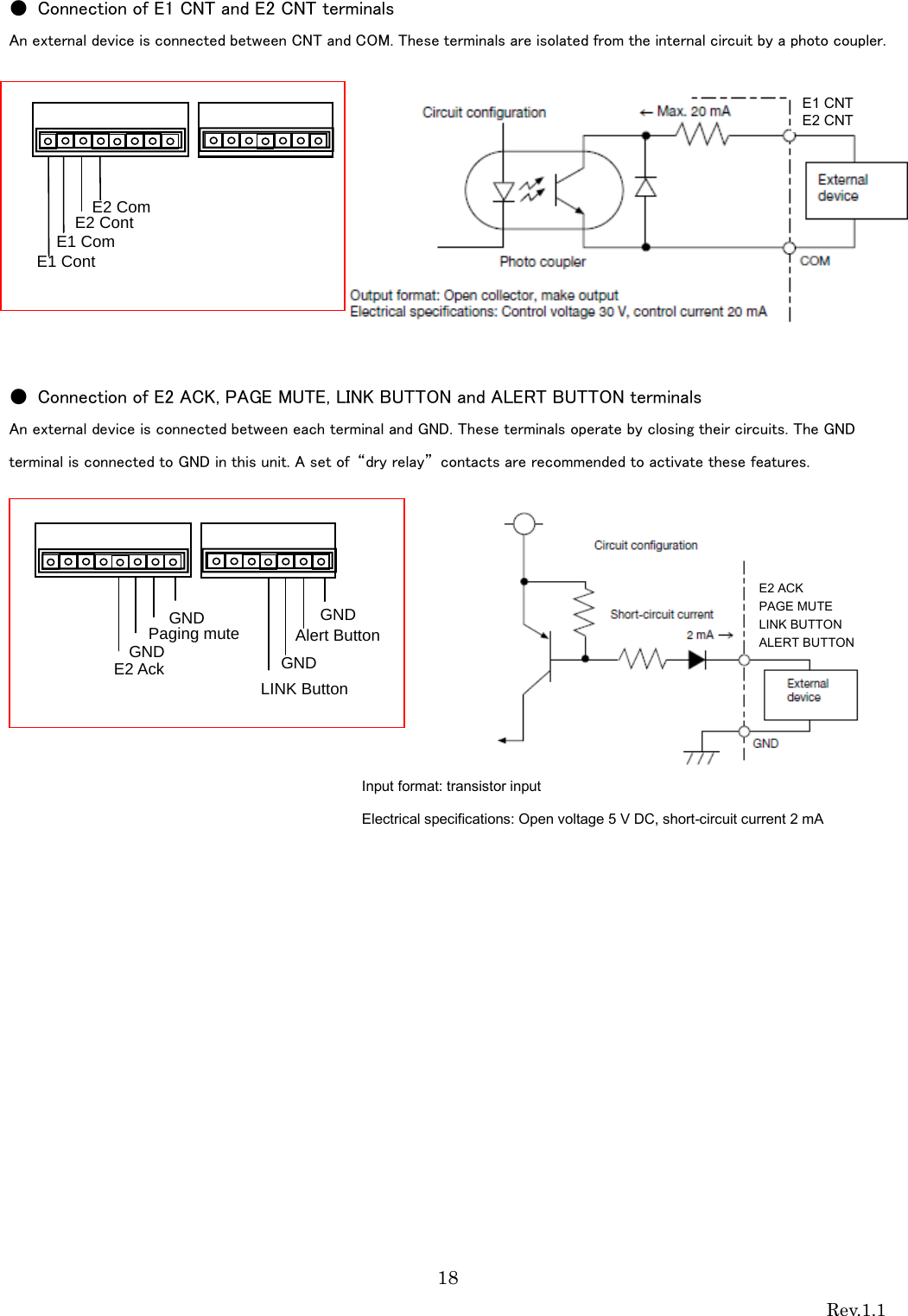
![13 Rev.1.1 ● E1 CNT, E2 CNT function These functions are available when K-STD14 is used. When E1 or E2 is controlled with the microphone, control signals are provided from the E1 CNT or E2 CNT terminal of this unit. Selection between E1 and E2 is made at the microphone side. E1: Default setting is Open. Press the button [REC] of the microphone to select the close state of 300 ms. E2: Default setting is Open. Press the both sides [E2] button simultaneously of the microphone for 2 seconds or more or press the alert button to select the close state. ● E2 ACK function When make signal inputs are provided to E2 ACK of the control terminals during E2 operation, the MIC1 or MIC2 LED indicator of this unit, MIC1 or MIC2 turns from red to green to indicate that the E2 ACK signal is received. When the E2 control input has not been provided from the microphone for 3 minutes after turning off the power of the microphone, the E2 state ends, the MIC1 or MIC2 LED indicator indicates the receiving state, and the operation LED turns from red to green to indicate the operating state.](https://usermanual.wiki/Panasonic-of-North-America/9TAK-SRC14/User-Guide-2471606-Page-13.png)
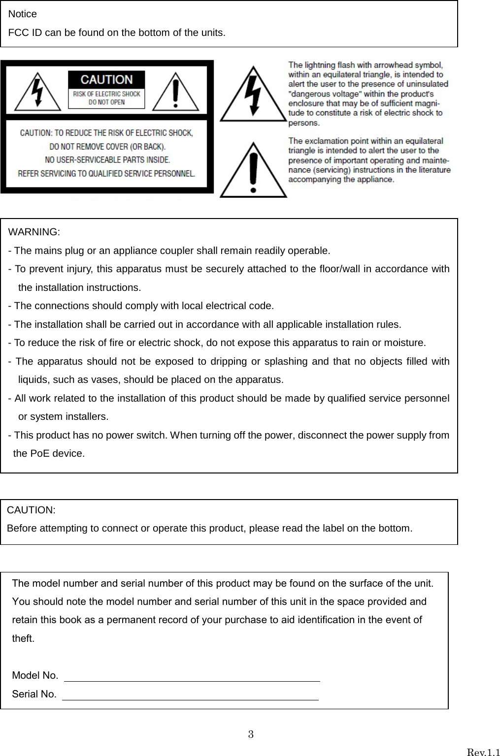
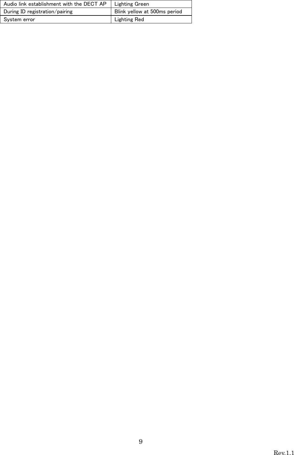
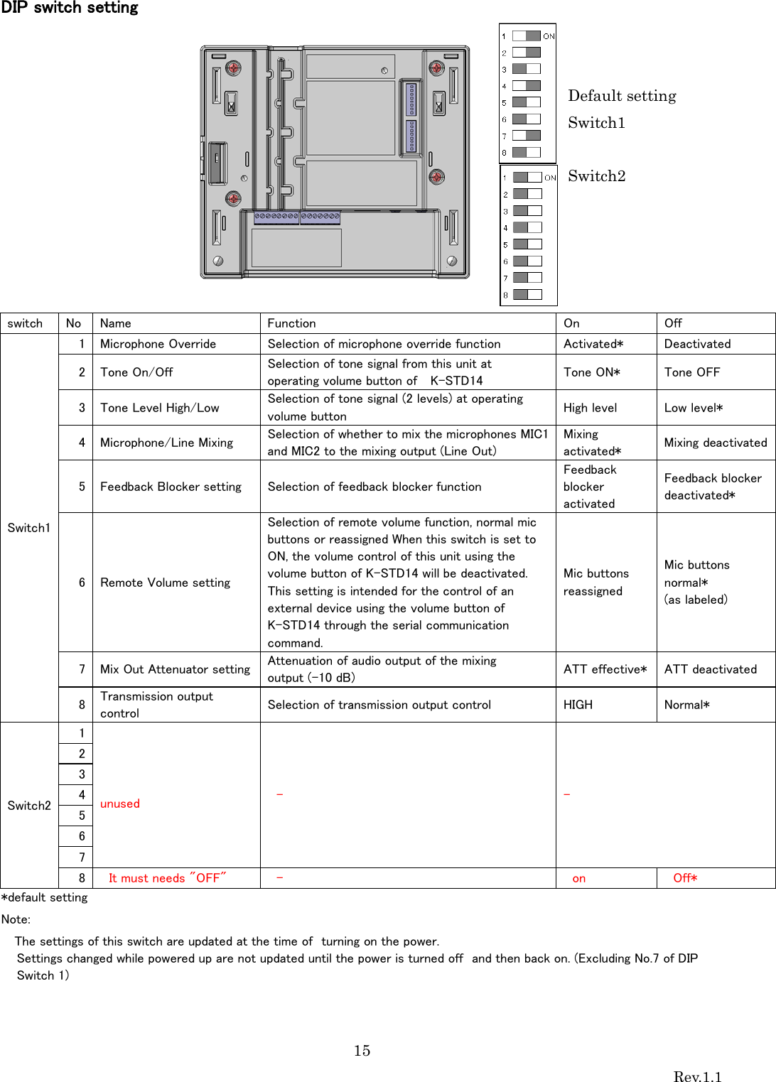
![14 Rev.1.1 LED lighting indication1[POWER/MIC1/MIC2] Three LEDs of this unit operate as an operation indicator indicating the state in operation and as a reception indicator indicating the receiving state of the microphone under normal conditions. In addition to those above, the LEDs operate as an indication LED indicating the operating state of this unit. Those LEDs indicate operating states as shown in the table. Furthermore, the priority order of indications is dependent on operating states. *1 E1 and E2 signal outputs and operating the volume button are available only with the microphone, K-STD14. *2 The indicator lights green again 3 minutes after the E2 signal is turned off with the microphone, K-STD14 LED Indication 2 [LINK LED] LINK LED is normally off. When an LINK key is pressed, the LINK LED blinks yellow at 20s.(ID registration/pairing mode) ・LED color will change according to priority. Show in below * If there is no special mention, when a function is completed or time passed, the LED state is restored to before changing. Indication priority Operating state LED indication MIC1 POWER MIC2 1 (highest) E2 signal output provided*1 Red (Lighting green at E2 ACK input provided) Red *2 (Lighting green at Power OFF) Red (Lighting green at E2 ACK input provided) 2 Paging mute signal input Yellow Yellow Yellow 3 E1 signal output provided*1 Red (Lighting for 300 ms) Green Red (Lighting for 300 ms) 4 Microphone volume button operated*1 No lighting (No lighting for 300 ms at operating volume button) Green No lighting (No lighting for 300 ms at operating volume button) 5 Feedback blocker operated Yellow (Lighting for 5s) Green Yellow (Lighting for 5s) 6 Audio link establishment Green Green Green 7 (lowest) Power ON No lighting Green No lighting Status LED indication LINK System error Red During ID registration/ pairing Blink yellow at 20s period Audio link establishment with the DECT AP Green Power ON No lighting](https://usermanual.wiki/Panasonic-of-North-America/9TAK-SRC14/User-Guide-2471606-Page-14.png)
![26 Rev.1.1 Serial communication command Serial communication command ■ Preface Use of the serial command allows the volume of this unit and settings of functions (page 13) with the DIP switch to be an external device remotely controlled. Note: • The settings of the functions that can be set with the DIP switch can be overwritten by sending a serial command. The serial command has the higher priority and will override the DIP switch settings. The unit will default back to the DIP switch settings when the power is cycled. (Excluding No. 7 of DIP switch1) ■ Basic format The serial command employs a common format to the commands of both from a control device to this unit and from this unit to a control device, and the format is categorized into 3 patterns as follows: When no parameter: "$" as a starting character, command, the control code, "CR" and "LF", as the termination character. When a single parameter: "$" as a starting character, command, colon, 1st parameter, the control code, "CR" and "LF", as the termination character. When the two parameters: "$" as a starting character, command, colon, 1st parameter, colon, 2nd param • All of $, CR, LF, : (colon) are fixed single byte, and the command part is fixed 3 bytes. • The length of the parameter part is basically single byte. As an exception, only the 2nd parameter is 2 bytes for the volume setting command. • If a command containing a failure in the command part or format is transmitted to this unit, $ER1[CR][LF] is returned from this unit. • If a command containing a failure in the parameter part is transmitted to this unit, $ER2[CR][LF] is returned from this unit. • When a timeout error occurs on the receiving timer (30 seconds) between each byte, $ER3[CR][LF] is returned. Note: • When commands are successively transmitted, keep 300 ms or more between successive commands that are transmitted to this unit.](https://usermanual.wiki/Panasonic-of-North-America/9TAK-SRC14/User-Guide-2471606-Page-26.png)
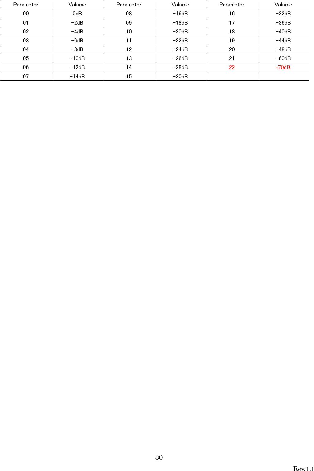
![27 Rev.1.1 Command List Command Content Type 1st parameter 2nd parameter Command example QPW Query about this unit power state Query None None $QPW[CR][LF] Response 1: POWER ON None $QPW:1[CR][LF] CCS Notification of microphone power state Change notification 1: MIC1 input 2: MIC2 input 0: MIC OFF 1: MIC ON $CCS:1:1[CR][LF] QCS Query about microphone power state Query 1: MIC1 input 2: MIC2 input None $QCS:1[CR][LF] Response Same as above 0: MIC OFF 1: MIC ON $QCS:1:0[CR][LF] SVL Volume setting Setting 1: MIC1 input 2: MIC2 input L: LINE input * Refer to “Volume list ” (page 32). $SVL:L:00[CR][LF] Response Same as above Same as above $SVL:L:00[CR][LF] SVU Volume 1-step up Setting 1: MIC1 input 2: MIC2 input L: LINE input None $SVU:1[CR][LF] Response Same as above None $SVU:1[CR][LF] SVD Volume 1-step down Setting 1: MIC1 input 2: MIC2 input L: LINE input None $SVD:2[CR][LF] Response Same as above None $SVD:2[CR][LF] QVL Volume query Query 1: MIC1 input 2: MIC2 input L: LINE input None $QVL:1[CR][LF] Response Same as above * Refer to “Volume list” (page 32). $QVL:1:01[CR][LF] SMT Mute individual setting Setting 1: MIC1 output 2: MIC2 output M: MIX output 0: MUTE OFF 1: MUTE ON $SMT:1:0[CR][LF] Response Same as above Same as above $SMT:1:0[CR][LF] QMT Mute state query Query 1: MIC1 output 2: MIC2 output M: MIX output Same as above $QMT:M[CR][LF] Response Same as above 0: MUTE OFF 1: MUTE ON $QMT:M:0[CR][LF] SAM Mute collective setting Setting 0: MUTE OFF 1: MUTE ON None $SAM:1[CR][LF] Response Same as above None $SAM:1[CR][LF] CPM Notification of page mute state Change notification 0:PAGE MUTE OFF 1:PAGE MUTE ON None $CPM:1[CR][LF] QPM Query about page mute state Query None None $QPM[CR][LF] Response 0:PAGE MUTE OFF 1:PAGE MUTE ON $QPM:0[CR][LF] CF1 Notification of E1sta Change notification None None $CF1[CR][LF] CF2 Notification of E2 state * 3-time transmission at 1 sec. interval Change notification 0: Non E2 status 1: E2 status & E2 ACK signal not received 2: E2 status & E2 ACK signal received None $CF2:1[CR][LF] CF2 Query about E2 state Query None None $QF2[CR][LF] Response 0: Non E2 status 1: E2 status & E2 ACK signal not received 2: E2 status & E2 ACK signal received None $QF2:2[CR][LF] SDS Microphone Override setting Setting 1: Microphone Override 0: Disable 1: Enable $SDS:1:0[CR][LF] Response Same as above Same as above $SDS:1:0[CR][LF]](https://usermanual.wiki/Panasonic-of-North-America/9TAK-SRC14/User-Guide-2471606-Page-27.png)
![28 Rev.1.1 Command Content Type 1st parameter 2nd parameter Command example SDS Tone setting Setting 2: Tone 0: Disable 1: Enable $SDS:2:1[CR][LF] Response Same as above Same as above $SDS:2:1[CR][LF] Tone Level setting Setting 3: Tone Level 0: Low, 1: High $SDS:3:0[CR][LF] Response Same as above Same as above $SDS:3:0[CR][LF] Microphone/Line Mixing setting Setting 4: Microphone/Line Mixing 0: Disable 1: Enable $SDS:4:1[CR][LF] Response Same as above Same as above $SDS:4:1[CR][LF] Feedback Blocker setting Setting 5: Feedback Blocker 0: Disable 1: Enable $SDS:5:0[CR][LF] Response Same as above Same as above $SDS:5:0[CR][LF] Remote Volume setting Setting 6: Remote Volume 0: Disable 1: Enable $SDS:6:1[CR][LF] Response Same as above Same as above $SDS:6:1[CR][LF] QDS* State query of Microphone Override setting Query 1: Microphone Override None $QDS:1[CR][LF] Response Same as above 0: Disable 1: Enable $QDS:1:0[CR][LF] State query of Tone setting Query 2: Tone None $QDS:2[CR][LF] Response Same as above 0: Disable 1: Enable $QDS:2:1[CR][LF] State query of Tone Level setting Query 3: Tone Level None $QDS:3[CR][LF] Response Same as above 0: Low, 1: High $QDS:3:0[CR][LF] State query of Microphone/Line Mixing setting Query 4: Microphone/Line Mixing None $QDS:4[CR][LF] Response Same as above 0: Disable 1: Enable $QDS:4:1[CR][LF] State query of Feedback Blocker setting Query 5: Feedback Blocker None $QDS:5[CR][LF] Response Same as above 0: Disable 1: Enable $QDS:5:0[CR][LF] State query of Remote Volume setting Query 6: Remote Volume None $QDS:6[CR][LF] Response Same as above 0: Disable 1: Enable $QDS:6:1[CR][LF] CVU Notification of volume up operation from microphone Change notification 1: MIC1 input volume up 2: MIC2 input volume up L:LINE input volume up None $CVU:1[CR][LF] CVD Notification of volume down operation from microphone Change notification 1: MIC1 input volume down 2: MIC2 input volume down L: LINE input volume down None $CVD:L[CR][LF] SRS Reset volume and E1/E2 states Setting None None $SRS[CR][LF] Response None None $SRS[CR][LF] CMI Change notification of microphone ID registration Change notification Microphone (DECT ID) DECT ID (20 bits) is specified by the character string (5 bytes) of a hexadecimal form. Receiver (DECT ID) DECT ID (20 bits) is specified by the character string (5 bytes) of a $CMI:12345:23456[CR][LF]](https://usermanual.wiki/Panasonic-of-North-America/9TAK-SRC14/User-Guide-2471606-Page-28.png)
![29 Rev.1.1 hexadecimal form. Response None None $CMI:11H,22H,33H,44H,55H: 12H,23H,34H,56H, 78H [CR][LF] ALM Alert Change notification Refer to (*1) Refer to (*1) $ALM: 11H,22H,33H,44H,55H: 12H,23H,34H,56H, 78H:1:63[CR][LF] ALB Alert message from alert Button Change notification Microphone (DECT ID) DECT ID (20 bits) is specified by the character string (5 bytes) of a hexadecimal form. None $ALB:23456[CR][LF] RAL Release Alert Setting None None $RAL[CR][LF] Response None None $RAL[CR][LF] ALL Alert message Location Change notification The number of alert messages N (N=1-5) (Parameter 2 -6) RF signal strength: 0-63 is specified by the character string (2 bytes) of a hexadecimal form. $ALL:2:12345:23456:1:34:12345:78910:0:20[CR][LF] CAA Change Microphone's transmission area for audio Setting The threshold level of the signal strength of RCV for making a microphone mute 0:Default 1: Area1 2: Area2 3: Area3 - $SAA:1[CR][LF] *An area of default setting is same as an area of “RF Tx power setting” of DIP SWITCHES. Default > Area1 > Area2 > Area3 Each QDS response command returns not the physical ON/OFF status of the DIP switch but the current setting status (*1) Parameter of ALM command. Parameter Content Comment Parameter1 Alert information Microphone (DECT ID) DET ID (20 bits) is specified by the character string (5 bytes) of a hexadecimal form. Parameter2 Receiver /DECT AP (DECT ID) DECT ID (20 bits) is specified by the character string (5 bytes) of a hexadecimal form. Parameter3 Paring status bit: 0 = not paired, 1 = paired The connection state of Microphone and Receiver before activating an Alert. Parameter4 RF signal strength: 0-63 is specified by the character string (2 bytes) of a hexadecimal form. It is a linear value showing signal strength.](https://usermanual.wiki/Panasonic-of-North-America/9TAK-SRC14/User-Guide-2471606-Page-29.png)