Panasonic of North America 9TAK-SRC14 1.9 GHz Wireless Receiver User Manual
Panasonic Corporation of North America 1.9 GHz Wireless Receiver Users Manual
Users Manual
1
Rev.1.1
1.9GHz Wireless Receiver
K-SRC14

2
Rev.1.1
FCC CAUTION
Changes or modifications not expressly approved by the party responsible for compliance could
void the user’s authority to operate the equipment.
This device complies with part 15 of the FCC Rules. Operation is subject to the following two
conditions: (1) This device may not cause harmful interference, and (2) this device must accept
any interference received, including interference that may cause undesired operation.
Note: This equipment has been tested and found to comply with the limits for a Class A digital
device, pursuant to part 15 of the FCC Rules. These limits are designed to provide reasonable
protection against harmful interference when the equipment is operated in a commercial
environment. This equipment generates, uses, and can radiate radio frequency energy and, if not
installed and used in accordance with the instruction manual, may cause harmful interference to
radio communications. Operation of this equipment in a residential area is likely to cause harmful
Compliance with FCC requirement 15.407(c)
Data transmission is always initiated by software, which is the passed down through the MAC,
through the digital and analog baseband, and finally to the RF chip. Several special packets are
initiated by the MAC. These are the only ways the digital baseband portion will turn on the RF
transmitter, which it then turns off at the end of the packet. Therefore, the transmitter will be on
only while one of the aforementioned packets is being transmitted. In other words, this device
automatically discontinue transmission in case of either absence of information to transmit or
operational failure.
Radio Frequency (RF) Exposure Warning
This equipment complies with FCC radiation exposure limits set forth for an uncontrolled
environment and meets the FCC radio frequency (RF) Exposure Guidelines. This equipment
should be installed and operated keeping the radiator at least 20cm or more away from person’s
body (excluding extremities: hands, wrists, feet and ankles).
MEDICAL:
Consult the manufacturer of any personal medical devices, such as pacemakers, to determine if
they are adequately shielded from external RF (radio frequency) energy. The unit operates in the
frequency range of 1.92 GHz to 1.93 GHz.
Do not use the unit in health care facilities if any regulations posted in the area instruct you not to
do so. Hospitals or health care facilities may be using equipment that could be sensitive to
external RF (radio frequency) energy.
3
Rev.1.1
Notice
FCC ID can be found on the bottom of the units.
WARNING:
- The mains plug or an appliance coupler shall remain readily operable.
- To prevent injury, this apparatus must be securely attached to the floor/wall in accordance with
the installation instructions.
- The connections should comply with local electrical code.
- The installation shall be carried out in accordance with all applicable installation rules.
- To reduce the risk of fire or electric shock, do not expose this apparatus to rain or moisture.
- The apparatus should not be exposed to dripping or splashing and that no objects filled with
liquids, such as vases, should be placed on the apparatus.
- All work related to the installation of this product should be made by qualified service personnel
or system installers.
- This product has no power switch. When turning off the power, disconnect the power supply from
the PoE device.
CAUTION:
Before attempting to connect or operate this product, please read the label on the bottom.
The model number and serial number of this product may be found on the surface of the unit.
You should note the model number and serial number of this unit in the space provided and
retain this book as a permanent record of your purchase to aid identification in the event of
theft.
Model No.
Serial No.

4
Rev.1.1
Important safety instructions
1) Read these instructions.
2) Keep these instructions.
3) Heed all warnings.
4) Follow all instructions.
5) Do not use this apparatus near water.
6) Clean only with dry cloth.
7) Do not block any ventilation openings. Install in accordance with the manufacturer's instructions.
8) Do not install near any heat sources such as radiators, heat registers, stoves, or other apparatus (including
amplifiers) that produce heat.
9) Protect the power cord from being walked on or pinched particularly at plugs, convenience receptacles, and
the point where they exit from the apparatus.
10) Only use attachments/accessories specified by the manufacturer.
11) Use only with the cart, stand, tripod, bracket, or table specified by the manufacturer, or sold with the
apparatus. When a cart is used, use caution when moving the cart/apparatus combination to avoid injury
from tip-over.
12) Unplug this apparatus during lightning storms or when unused for long periods of time.
13) Refer all servicing to qualified service personnel. Servicing is required when the apparatus has been
damaged in any way, such as power-supply cord or plug is damaged, liquid has been spilled or objects
have fallen into the apparatus, the apparatus has been exposed to rain or moisture, does not operate
normally, or has been dropped.
14) Make sure that the wall that the shelf will be attached to is strong enough to support the shelf. If not, it is
necessary for the wall to be reinforced.
15) For safety reasons, do not physically modify the product or any optional equipment.
16) To prevent possible fire or electric shock, do not expose this product to rain or moisture.
17) Follow all warnings and instructions marked on this product.
18) To reduce the risk of electric shock, do not disassemble this product. Only qualified personnel should
service this product. Opening or removing covers may expose you to dangerous voltages or other risks.
Incorrect reassembly can cause electric shock.
19) Unplug the AC adaptor from the AC outlet and have the product serviced by qualified service personnel in
the following cases:
A. When the power supply cord or plug is damaged or frayed.
B. If liquid has been spilled into this product.
5
Rev.1.1
C.
If the product has been exposed to rain or water.
D. If the product does not operate according to this manual. Adjust only the controls that are explained in
this manual. Improper adjustment of other controls may result in damage and may require service by a
qualified technician to restore the product to normal operation.
E.
If the product has been dropped or damaged.
F. If product performance deteriorates.
20) The product should never be placed near or over a radiator or other heat source.
21) Do not use a microwave oven to dry this product.
22) The product may only be installed and serviced by qualified service personnel.
6
Rev.1.1
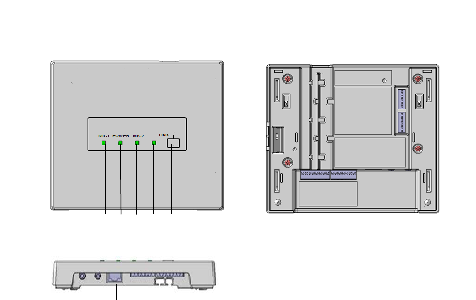
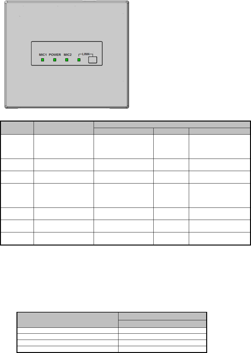
Major operating controls and their functions
[1][LINK] button
Pressing this button will becomes register mode with a microphone.
(Linkup connection is established or progress of 20 seconds will cancel this mode.)
Refer to Operating procedures.
[2] POWER indicator [POWER]
(Green/Yellow/Red)
This LED lights green when the power is on and this unit is receivable under normal conditions.
This LED lights as follows to indicate other states:
E2 signal output provided: lighting red (Lighting green at Power OFF)
Page mute signal received: lighting yellow
[3]MIC1/MIC2 indicator [MIC1/MIC2]
This LED lights green when this unit is receiving signals from each microphone under normal conditions.
This LED lights as follows to indicate other states:
E2 signal output provided: lighting red. (Lighting green at E2 ACK input provided)
Page mute signal received: lighting yellow
E1 signal output provided: lighting (300ms) red
Feedback blocker in operation: lighting(5sec) yellow
[4] LINK indicator [LINK]
This LED lights yellow(500ms) when this unit is during ID registration(Pairing)
This LED lights red when this unit is system error
4 1 2
3
3
9
8
7
6
5
7
Rev.1.1
[5]Control terminals
8-pin and 7-pin Euro blocks are used.
The following terminals are equipped.
E1 CNT: provides E1 signal * output controlled by K-STD14.
E2 CNT: provides E2 signal * output controlled by K-STD14.
* Those are available when K-STD14 is used. Settings of E1 and E2 are performed with K-STD14.
E2 ACK: connects acknowledge signals responding to E2 output.
PAGE MUTE: provides make signal inputs externally when the paging function is used.
RS-232C: is used to control this unit via communication from an external device.
LINK button: provides make signal inputs externally when the external link button is used.
Alert notification button; provides make signal inputs externally when the external Alert notification button is used.
[6] Amplifier interface connector
This connector is used to connect the cable to the amplifier.
A standard CAT5 or CAT5e cable is used to connect to the amplifier.
[7] MIX OUT (unbalanced) connector
This connector provides the audio output of LINE IN of the main unit. Setting the No. 4 of the DIP switch1 to ON allows the audio
outputs of the microphone CH1 and CH2 received by this unit to be provided after mixing with LINE IN. This is an unbalanced
output. A stereo mini plug (φ3.5 mm) is used.
[8] LINE IN connector
This connector is used to provide an audio input from external sources such as a projector or CD. This is a stereo, line level input,
and is internally mixed to a monaural signal. A stereo mini plug (φ3.5 mm) is used.
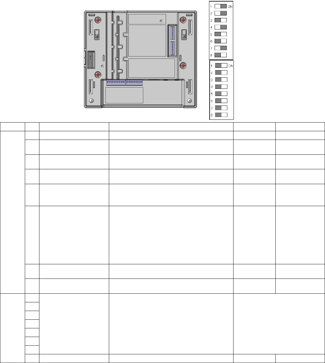
[9]DIP Switches
Two DIP switches are used.
The settings of this switch are updated at the time of turning on the power.
Settings changed while powered up are not updated until the power is turned off and then back on. (Excluding No.7 of DIP
Switch 1)
8
Rev.1.1
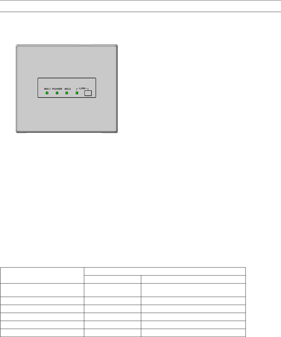
Operating procedures
1.
A standard CAT5 or CAT5e cable is used to connect to the amplifier,. After that, turned on amplifier.
The POWER LED of the receiver lights green.
2. Power ON of the microphone .
[K-STD14] : Turn on the [PWR/MUTE] button.
[K-SHH14] : Turn on the [PWR LINK] button. And Push [TALK push]button.
The MIC1 or MIC2 LED indicator of the lights green ( depending on a channel to be received.)
3 .Adjust the volume of external devices such as an amplifier.
The overall volume is adjusted with the external amplifier or the like. Use of the volume button of K-STD14 allows the volume of
itself to be adjusted. In addition, selection of the target with the selection button of K-STD14 allows the volume of the other
microphone received by this unit and the volume of LINE IN of this unit to be adjusted.
4. The LED of the POWER/MIC1/MIC2 indicates the operating state of this unit during operation.
LED
POWER indicator
MIC1/MIC2 indicator
E2 signal output provided* Lighting red Lighting red
(lighting green at E2 ACK input provided)
E1 signal output provided* Lighting green Lighting red (for 300 ms)
Page mute signal input provided Lighting yellow Lighting yellow
Microphone volume operated* Lighting green No lighting (for 300 ms)
Feedback blocker operated Lighting green Lighting yellow (for 5 s)
Audio link establishment Lighting green Lighting green
* Applicable when K-STD14 is used
5. The LED of the LINK indicates the operating state of this unit during operation.

9
Rev.1.1
Audio link establishment with the DECT AP Lighting Green
During ID registration/pairing Blink yellow at 500ms period
System error Lighting Red
10
Rev.1.1
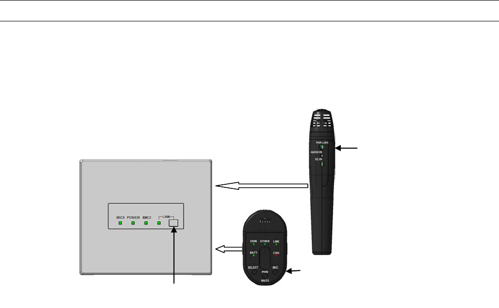
Connection registration of the microphone to a receiver
When connecting it with the receiver which has not connected once, pairing registration is needed first.
Please perform pairing registration according to the following procedure.
(Only the alert operates without registration work.)
1. Press a receiver's [LINK] button, and a receiver is made into register mode
.
2. (a) Pendant microphone:
Press [PWR/MUTE] button and [REC] button will register for receiver.
Pendant microphone [BATT] indicator is green light.
(b)Handheld microphone:
Microphone LINK switch (inside the battery cover) is ON. (Different receiver connection)
(Please read the operating instructions of the Handheld Microphone (K-SHH14).)
Press [PWR LINK] button will register for receiver.
Handheld microphone [BATT] indicator is blinking ( green ).
A pairing setup is required first.
1.
[LINK] button
[PWR LINK] button
[PWR/MUTE] button

11
Rev.1.1
Classroom Audio
Pendant Microphone [K-STD14]
1. Press [PWR/MUTE] button will start a microphone.
A microphone can be used in a classroom. (MIC1 or MIC2 LED indicator lighting green)
Note:
• Also read the operating instructions of the Pendant Microphone (K-STD14).
Handheld Microphone [K-SHH14]
1. Press [PWR LINK] button will start a microphone.
2. Press [TALK push] button will start a microphone.
A microphone can be used in a classroom. (MIC2 or MIC1 LED indicator lighting green)
Note:
• Also read the operating instructions of the Handheld Microphone (K-SHH14).
12
Rev.1.1
Functions
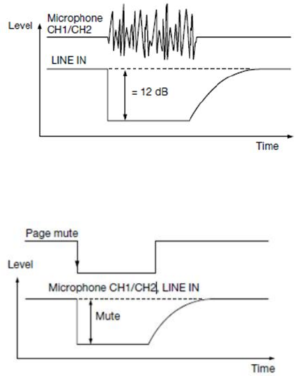
● Microphone override function
This is a function where the audio level of LINE IN is automatically adjusted to lower when the audio input of the microphone MIC1
or microphone MIC2 is provided. The attenuation of the audio level is –12 dB.
When the audio input of the microphone 1 or microphone2 is not provided any more, the volume of LINE IN automatically returns to
the previous level.
● Paging mute function
This is a function where the audio outputs of the microphoneMIC1, microphone MIC2, and mixing output of this unit are muted by
closing the PAGE MUTE terminal.
This function is specified with the Control terminal or RS-232C. This function is set to OFF at default settings.
● Tone function
This is a function where the operation sound output is provided from the MIX OUT connector when the volume button is operated
with the optional microphone, K-STD14. The operation sound is generated twice at the maximum and minimum volumes.
The level of the operation sound can be selected to HIGH or LOW with the DIP switch. The level is set to LOW at default settings.
The level is set to LOW at default settings.
This function is specified with the DIP switch. This function is set to OFF at default settings.
● Microphone/line mixing function
This function is designed to assign the microphones MIC1 and MIC2 to the mixing out, and two signals will be mixed with the mixing
out.
This function is specified with the DIP switch. No mixing is provided at default settings.
● Remote volume function
This is a function where the volume of this unit cannot be adjusted with the volume button of the optional microphone, K-STD14.
This function is used when external devices are controlled with the volume button through the use of the communication control
function of this unit.
This function is specified with the DIP switch. The volume can be controlled with the microphone at default settings.
● Mixing output attenuator function
Setting the mixing output attenuator to ON provides attenuation in the mixing output by 10 dB.
This function is useful when a device with high input sensitivity is connected.
This function is specified with the DIP switch. The output is set to –10 dB at default settings.
■ About the feedback blocker
This is a function where the feedback loop generated when the microphone and speaker approach each other is reduced.
An integrated filter is automatically selected according to the generated audio frequency, and reduces the uncomfortable feedback
loop.
This function is specified with the DIP switch. This function is set to OFF at default settings.
Note:
• This function is simplified, and cannot fully remove the feedback loop. When the feedback loop is extremely large, this function will
work to mute all the audio outputs of this unit.
13
Rev.1.1
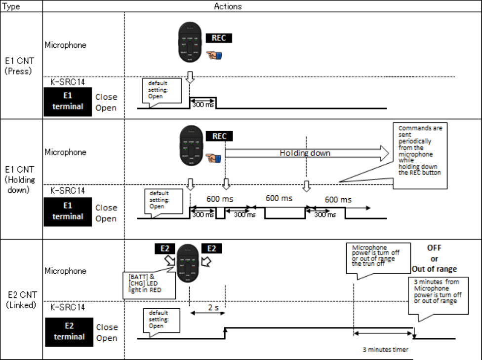
● E1 CNT, E2 CNT function
These functions are available when K-STD14 is used. When E1 or E2 is controlled with the microphone, control signals are provided
from the E1 CNT or E2 CNT terminal of this unit. Selection between E1 and E2 is made at the microphone side.
E1: Default setting is Open.
Press the button [REC] of the microphone to select the close state of 300 ms.
E2: Default setting is Open.
Press the both sides [E2] button simultaneously of the microphone for 2 seconds or more or press the alert button to select the
close
state.
● E2 ACK function
When make signal inputs are provided to E2 ACK of the control terminals during E2 operation, the MIC1 or MIC2 LED indicator of
this unit, MIC1 or MIC2 turns from red to green to indicate that the E2 ACK signal is received.
When the E2 control input has not been provided from the microphone for 3 minutes after turning off the power of the microphone,
the E2 state ends, the MIC1 or MIC2 LED indicator indicates the receiving state, and the operation LED turns from red to green to
indicate the operating state.
14
Rev.1.1
LED lighting indication1[POWER/MIC1/MIC2]
Three LEDs of this unit operate as an operation indicator indicating the state in operation and as a reception indicator indicating the
receiving state of the microphone under normal conditions. In addition to those above, the LEDs operate as an indication LED
indicating the operating state of this unit. Those LEDs indicate operating states as shown in the table.
Furthermore, the priority order of indications is dependent on operating states.
*1 E1 and E2 signal outputs and operating the volume button are available only with the microphone, K-STD14.
*2 The indicator lights green again 3 minutes after the E2 signal is turned off with the microphone, K-STD14
LED Indication 2 [LINK LED]
LINK LED is normally off.
When an LINK key is pressed, the LINK LED blinks yellow at 20s.(ID registration/pairing mode)
・LED color will change according to priority. Show in below
* If there is no special mention, when a function is completed or time passed, the LED state is restored to before changing.
Indication
priority
Operating state
LED indication
MIC1
POWER
MIC2
1
(highest)
E2 signal output
provided*1
Red
(Lighting green at E2
ACK input provided)
Red
*2
(Lighting
green at
Power OFF)
Red
(Lighting green at E2
ACK input provided)
2
Paging mute signal
input
Yellow
Yellow
Yellow
3
E1 signal output
provided*1
Red
(Lighting for 300 ms)
Green
Red
(Lighting for 300 ms)
4
Microphone volume
button operated*1
No lighting
(No lighting for 300 ms
at
operating volume
button)
Green
No lighting
(No lighting for 300 ms
at
operating volume
button)
5
Feedback blocker
operated
Yellow
(Lighting for 5s)
Green
Yellow
(Lighting for 5s)
6
Audio link
establishment
Green
Green
Green
7
(lowest)
Power ON
No lighting
Green
No lighting
Status
LED indication
LINK
System error
Red
During ID registration/ pairing
Blink yellow at 20s period
Audio link establishment with the DECT AP
Green
Power ON
No lighting
15
Rev.1.1
DIP switch setting
switch No Name Function On Off
Switch1
1 Microphone Override Selection of microphone override function Activated* Deactivated
2 Tone On/Off Selection of tone signal from this unit at
operating volume button of K-STD14 Tone ON* Tone OFF
3 Tone Level High/Low Selection of tone signal (2 levels) at operating
volume button High level Low level*
4 Microphone/Line Mixing
Selection of whether to mix the microphones MIC1
and MIC2 to the mixing output (Line Out)
Mixing
activated* Mixing deactivated
5 Feedback Blocker setting Selection of feedback blocker function
Feedback
blocker
activated
Feedback blocker
deactivated*
6 Remote Volume setting
Selection of remote volume function, normal mic
buttons or reassigned When this switch is set to
ON, the volume control of this unit using the
volume button of K-STD14 will be deactivated.
This setting is intended for the control of an
external device using the volume button of
K-STD14 through the serial communication
command.
Mic buttons
reassigned
Mic buttons
normal*
(as labeled)
7 Mix Out Attenuator setting Attenuation of audio output of the mixing
output (–10 dB) ATT effective* ATT deactivated
8 Transmission output
control Selection of transmission output control HIGH Normal*
Switch2
1
unused - -
2
3
4
5
6
7
8 It must needs "OFF" - on Off*
*default setting
Note:
The settings of this switch are updated at the time of turning on the power.
Settings changed while powered up are not updated until the power is turned off and then back on. (Excluding No.7 of DIP
Switch 1)
Default setting
Switch1
Switch2
16
Rev.1.1
Connections
.
■ Connection of receiver
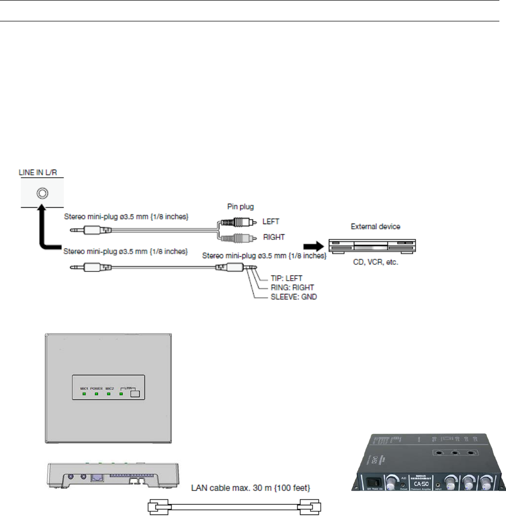
● LINE IN connection
Connect the audio output of a projector, CD player or DVD/VCR or similar line level output to the LINE IN connector of this unit.
The line input of this terminal is a stereo input. Audio signals are mixed to monaural signals internally. Cables should be selected
depending on the connector types of devices to be connected and follow the description below to connect external devices.
● INTERFACE CONNECTOR connection
Note:
• An RJ-45 type connector of this unit is based on our original system and electrical specifications. Never connect this terminal to
a LAN connector that is compatible with Ethernet and PoE (Power over Ethernet).
Never connect this connector to a LAN connector that is compatible with Ethernet and PoE (Power over Ether).
Be sure to make a connection when the power of this unit is set to OFF (No AC adaptor is allowed to be connected to the amplifier).
• If making an unbalanced connection for an audio output of this unit, use a STP (Shield Twisted Pair) LAN cable to prevent
exogenous noise.
Amplifier
17
Rev.1.1
● AUDIO OUT connection
Connect the audio input of a network camera or similar level input to the AUDIO OUT connector of this unit. The line output of this
terminal is a mono output. Cables should be selected depending on the connector types of devices to be connected and follow the
description below to connect external devices.
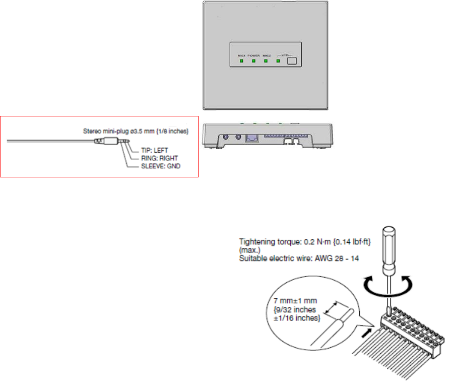
■ Connection to control terminal
● Cable processing
Before connection, prepare the cable as shown in the drawing at right.
Note:
• Stranded wire is highly recommended.
• Wire insulation must be removed.
• Do not use solder to tin the wire.
• The recommended maximum cable length is 15 m {49feet}.
18
Rev.1.1
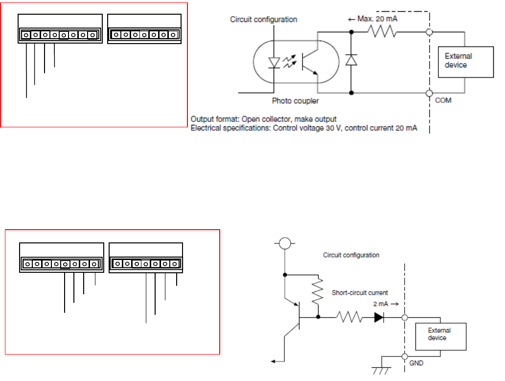
● Connection of E1 CNT and E2 CNT terminals
An external device is connected between CNT and COM. These terminals are isolated from the internal circuit by a photo coupler.
● Connection of E2 ACK, PAGE MUTE, LINK BUTTON and ALERT BUTTON terminals
An external device is connected between each terminal and GND. These terminals operate by closing their circuits. The GND
terminal is connected to GND in this unit. A set of “dry relay” contacts are recommended to activate these features.
Input format: transistor input
Electrical specifications: Open voltage 5 V DC, short-circuit current 2 mA
E1 CNT
E2 CNT
E2 ACK
PAGE MUTE
LINK BUTTON
ALERT BUTTON
E1 Cont
E1 Com
E2 Cont
E2 Com
E2 Ack
GND
Paging mute
GND
GND
LINK Button
Alert Button
GND
19
Rev.1.1
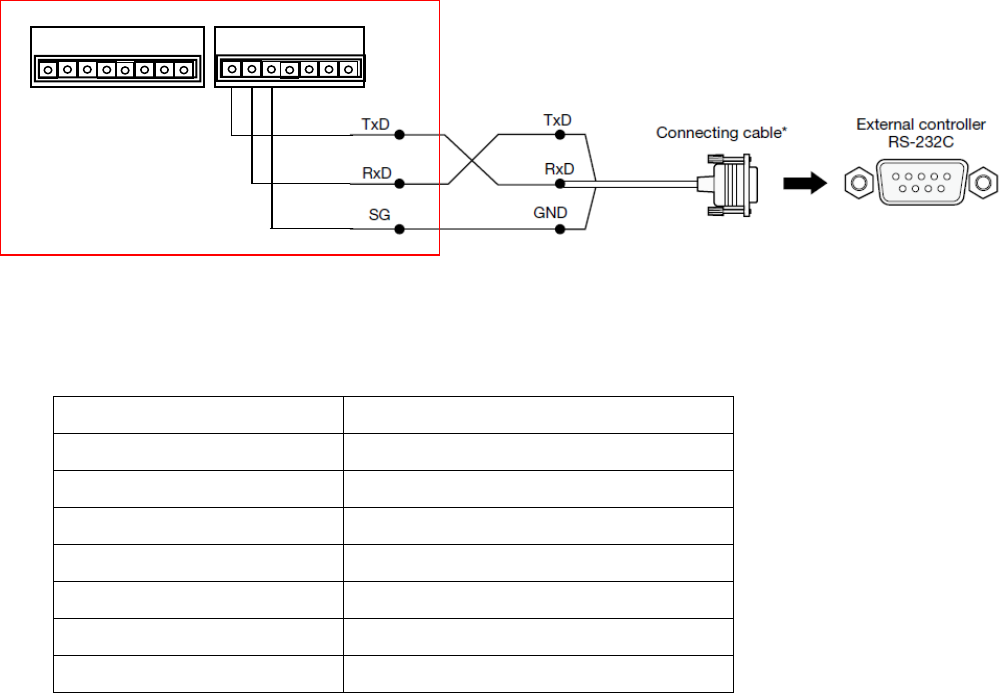
■ Connection of RS-232C
The K-SRC14 can send and receive commands and status information via RS-232C to external devices. The external device is
connected with a 3 wire cable. The cable should be cross-connected, in other words, the transmitting signal (TxD) of this unit is
connected to the receiving signal (RxD) of the external device, and the receiving signal (RxD) of this unit is connected to the
transmitting signal (TxD) of the external device. The ground signal of each device should be connected one another.
Cables to be connected should be selected depending on the external devices to be connected. The above illustrates
that the external device has a D-sub 9-pin connector.
Interface
RS-232C
Communication system Asynchronous
Baud rate 9600 bps
Data length 8 bits
Parity None
Stop bit 1 bit
Flow control None
Communication code ASCII character code

20
Rev.1.1
Precautions for installation
The installation should be carried out following local standards for electric products.
Warning
• Be sure to contact your dealer for installation.
Before installing, turn off the power of the connecting product. In addition, be sure to read "Precautions" carefully and follow the
instructions. Moreover, be sure to read operating instructions of the connecting product as well.
● Power
Connect the power plug of the AC adaptor by using a circuit breaker in any of the following ways:
Install this product near the power outlet.
Connect this product with the breaker of a distribution board which has a contact point of not less than 3.0 mm {3/32 inches}.
Use a breaker that can block all the poles except for protective earth conductors.
Connect this product via the outlets of devices that can block power such as a power control unit.
● Static Electricity
Discharge any static electricity charged in your body by touching a metallic area before installing in order to prevent damage caused
by static electricity.
● Install the receiver within a range that the microphone can reach and in a location that can be seen in moving range.
● Avoid installing near a warm air flow path. In addition, if the product is installed in locations with a lot of moisture, dust or
vibration, there is a risk of damage.
● Do not install and use in following locations:
1) Locations directly affected by rain or water (including spaces under the eaves).
2) Locations such as pool where medical agents are used.
3) Locations such as kitchen or factory workshop where there is a lot of vapor or oil and special environments such as in
flammable atmospheres.
4) Locations where radiation or X-rays and strong electric fields or magnetism arise.
5) At sea or along the coast, and locations such as hot springs where corrosive gases arise.
6) Locations with a lot of vibrations caused by vehicle or ships (this is not a product for vehicles).
7) Locations where water drops made by condensation will splash.
● If there are any devices releasing strong noises, product may sometimes be impossible to use. In that case, install the product
farther away until it can be used.
● For tightening bolts and screws, pay attention to following points:
1) Torque control is necessary for tightening the bolts and screws.
2) Torque wrench and torque driver are necessary for controlling the torque.
3) Never use any impact driver or electric drill because torque control is difficult even if they have a clutch. Their use may result
in damage to the mounting part.
● After mounting, confirm visually that the product is firmly and stably fixed. If the product is properly installed, it will not wobble
or make noise.
● In installing this receiver, be aware of the following:
1) Be sure that the installation is carried out by a qualified personnel when installing at high locations.
2) Before installation, confirm that there is nobody around.
3) In order to carry out the installation safely and surely, pay close attention to the safety control.
● Do not apply strong impact on this unit. Failure to observe this may damage this unit.

21
Rev.1.1
Installation.
Warning
• Before installing, be sure to turn off the power of the receiver.
There is a risk of electric shock.
■ Installation of the receiver
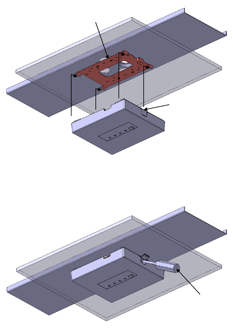
● When using a ceiling panel
When installing the receiver and cables in a removable ceiling, follow the instructions shown below.
1 Make a hole in the ceiling panel
Remove the ceiling panel, drill a hole of approx. φ35 mm {φ1-1/3 inches} through the panel, and run the cables to be connected
through the hole.
2 The ceiling panel is inserted on mount bracket and a plate, and it fixes with a screw and a nut.
Note:
• Fix this unit firmly with specified torque with a tool such as a torque driver.
3 Connect the necessary cables to the receiver.
Connect the cables refer to Connections.
4 Install the receiver.
A receiver is hooked on the hook of the mount bracket.(Four places)
Open the screw cover.
A receiver is fixed to mount bracket with a driver using an attached screw.
Close the screw cover.
Note:
• Fix this unit firmly with specified torque with a tool such as a torque driver.
5 After installation, check that all parts are firmly installed.
Check visually for loose parts and connections.
22
Rev.1.1
AE plate
Screw cover
Mount bracket
Ceiling Panel
Screw driver
Step 1
Step 2
23
Rev.1.1
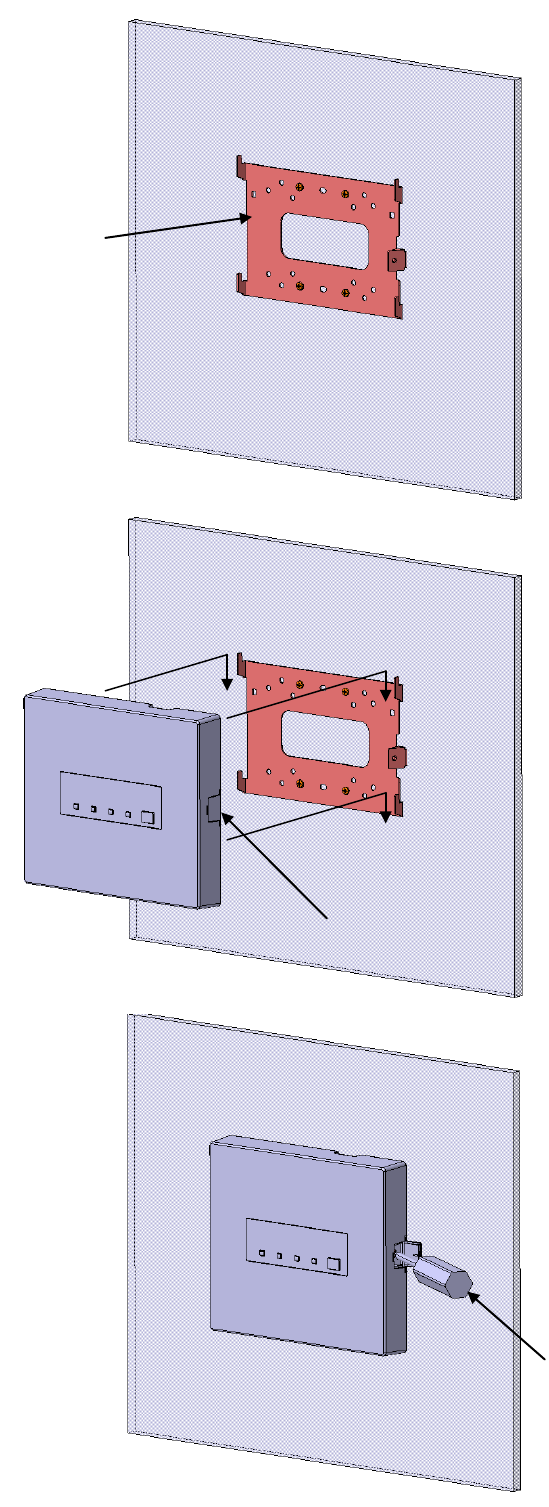
● When using a wall
When installing the receiver and cables in a removable wall, follow the instructions shown below.
1 The mount bracket is fixed to a wall with a driver using a screw.
Note:
• Fix this unit firmly with specified torque with a tool such as a torque driver.
2 Connect the necessary cables to the receiver.
Connect the cables refer to Connections.
3 Install the receiver.
A receiver is hooked on the hook of the mount bracket.(Four places)
Open the screw cover.
A receiver is fixed to mount bracket with a driver using an attached screw.
Close the screw cover.
Note:
• Fix this unit firmly with specified torque with a tool such as a torque driver.
4 After installation, check that all parts are firmly installed.
Check visually for loose parts and connections.
24
Rev.1.1
IMPORTANT:
• Procure 4 screws (M4) to secure the receiver attachment (accessory) to a ceiling or a wall
according to the material of the installation area. In this case, wood screws and nails should not
be used. For mounting a receiver on a concrete wall, use an anchor bolt (M4) or an AY plug bolt
(M4) for securing. (Recommended tightening torque: 1.6 N・m {1.18 lbf・ft})
• Mount the receiver attachment (accessory) in consideration of the camera angle in accordance
with the instructions
• Required pull-out capacity of a single screw/bolt is 196 N {44 lbf} or more.
• If a ceiling board such as plaster board is too weak to support the total weight, the area shall
be sufficiently reinforced.
• Install the receiver mount bracket (locally procured) in the foundation area of the architecture or
where sufficient strength is assured.
• To prevent the mounting strength from becoming lower, do not use wooden screws to secure
the receiver mount bracket (locally procured).
Installation place Applicable mount bracket Recommended screw Number of screw Minimum pull-out strength (per 1 pc.)
Wall Mounting plate (Accessory) M4 4 pcs. 196 N {44 lbf}
25
Rev.1.1
Screw cover
Mount bracket
Screw driver
Step 1
Step 2
Step 3
26
Rev.1.1
Serial communication command
Serial communication command
■ Preface
Use of the serial command allows the volume of this unit and settings of functions (page 13) with the DIP switch to be an external
device remotely controlled.
Note:
• The settings of the functions that can be set with the DIP switch can be overwritten by sending a serial command. The serial
command has the higher priority and will override the DIP switch settings. The unit will default back to the DIP switch settings when
the power is cycled. (Excluding No. 7 of DIP switch1)
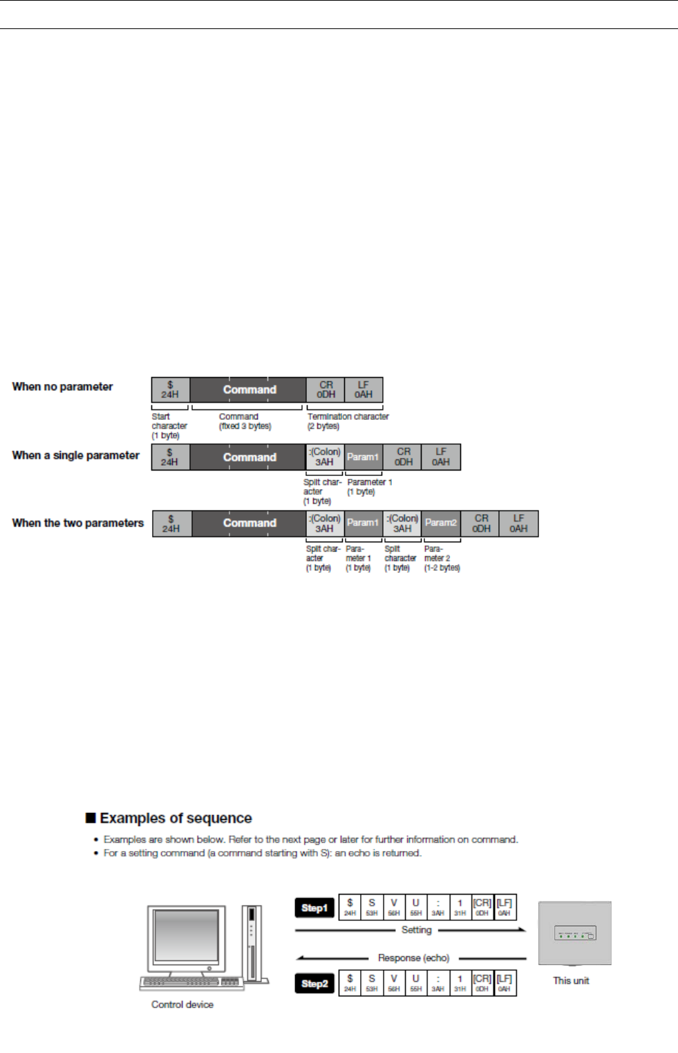
■ Basic format
The serial command employs a common format to the commands of both from a control device to this unit and from this unit to a
control device, and the format is categorized into 3 patterns as follows:
When no parameter:
"$" as a starting character, command, the control code, "CR" and "LF", as the termination character.
When a single parameter:
"$" as a starting character, command, colon, 1st parameter, the control code, "CR" and "LF", as the termination character.
When the two parameters:
"$" as a starting character, command, colon, 1st parameter, colon, 2nd param
• All of $, CR, LF, : (colon) are fixed single byte, and the command part is fixed 3 bytes.
• The length of the parameter part is basically single byte. As an exception, only the 2nd parameter is 2 bytes for the volume setting
command.
• If a command containing a failure in the command part or format is transmitted to this unit, $ER1[CR][LF] is returned from this
unit.
• If a command containing a failure in the parameter part is transmitted to this unit, $ER2[CR][LF] is returned from this unit.
• When a timeout error occurs on the receiving timer (30 seconds) between each byte, $ER3[CR][LF] is returned.
Note:
• When commands are successively transmitted, keep 300 ms or more between successive commands that are transmitted to this
unit.

27
Rev.1.1
Command List
Command
Content
Type
1st parameter
2nd parameter
Command example
QPW Query about this
unit power state
Query None None $QPW[CR][LF]
Response 1: POWER ON None $QPW:1[CR][LF]
CCS
N
otification of
microphone power
state
Change
notification
1: MIC1 input
2: MIC2 input
0: MIC OFF
1: MIC ON $CCS:1:1[CR][LF]
QCS
Query about
microphone power
state
Query 1: MIC1 input
2: MIC2 input None $QCS:1[CR][LF]
Response Same as above 0: MIC OFF
1: MIC ON $QCS:1:0[CR][LF]
SVL Volume setting Setting
1: MIC1 input
2: MIC2 input
L: LINE input
* Refer to
“Volume list ”
(page 32).
$SVL:L:00[CR][LF]
Response Same as above Same as above $SVL:L:00[CR][LF]
SVU Volume 1-step up Setting
1: MIC1 input
2: MIC2 input
L: LINE input
None $SVU:1[CR][LF]
Response Same as above None $SVU:1[CR][LF]
SVD Volume 1-step
down
Setting
1: MIC1 input
2: MIC2 input
L: LINE input
None $SVD:2[CR][LF]
Response Same as above None $SVD:2[CR][LF]
QVL Volume query
Query
1: MIC1 input
2: MIC2 input
L: LINE input
None $QVL:1[CR][LF]
Response Same as above
* Refer to
“Volume
list” (page 32).
$QVL:1:01[CR][LF]
SMT Mute individual
setting
Setting
1: MIC1 output
2: MIC2 output
M: MIX output
0: MUTE OFF
1: MUTE ON $SMT:1:0[CR][LF]
Response Same as above Same as above $SMT:1:0[CR][LF]
QMT Mute state query
Query
1: MIC1 output
2: MIC2 output
M: MIX output
Same as above $QMT:M[CR][LF]
Response Same as above 0: MUTE OFF
1: MUTE ON $QMT:M:0[CR][LF]
SAM Mute collective setting
Setting 0: MUTE OFF
1: MUTE ON None $SAM:1[CR][LF]
Response Same as above None $SAM:1[CR][LF]
CPM Notification of
page mute state
Change
notification
0:PAGE MUTE OFF
1:PAGE MUTE ON None $CPM:1[CR][LF]
QPM Query about page
mute state
Query None None $QPM[CR][LF]
Response 0:PAGE MUTE OFF
1:PAGE MUTE ON $QPM:0[CR][LF]
CF1 Notification of E1sta Change
notification None None $CF1[CR][LF]
CF2
Notification of E2
state
* 3-time transmission
at 1 sec.
interval
Change
notification
0: Non E2 status
1: E2 status & E2 ACK
signal not received
2: E2 status & E2 ACK
signal received
None $CF2:1[CR][LF]
CF2 Query about E2
state
Query None None $QF2[CR][LF]
Response
0: Non E2 status
1: E2 status & E2 ACK
signal not received
2: E2 status & E2 ACK
signal received
None $QF2:2[CR][LF]
SDS Microphone
Override setting
Setting 1: Microphone Override 0: Disable
1: Enable $SDS:1:0[CR][LF]
Response Same as above Same as above $SDS:1:0[CR][LF]

28
Rev.1.1
Command
Content
Type
1st parameter
2nd parameter
Command example
SDS
Tone setting Setting 2: Tone 0: Disable
1: Enable $SDS:2:1[CR][LF]
Response Same as above Same as above $SDS:2:1[CR][LF]
Tone Level
setting
Setting 3: Tone Level 0: Low, 1: High $SDS:3:0[CR][LF]
Response Same as above Same as above $SDS:3:0[CR][LF]
Microphone/Line
Mixing setting
Setting 4: Microphone/Line
Mixing
0: Disable
1: Enable $SDS:4:1[CR][LF]
Response Same as above Same as above $SDS:4:1[CR][LF]
Feedback Blocker
setting
Setting 5: Feedback
Blocker
0: Disable
1: Enable $SDS:5:0[CR][LF]
Response Same as above Same as above $SDS:5:0[CR][LF]
Remote Volume
setting
Setting 6: Remote Volume 0: Disable
1: Enable $SDS:6:1[CR][LF]
Response Same as above Same as above $SDS:6:1[CR][LF]
QDS*
State query of
Microphone
Override setting
Query 1: Microphone
Override None $QDS:1[CR][LF]
Response Same as above 0: Disable
1: Enable $QDS:1:0[CR][LF]
State query of
Tone setting
Query 2: Tone None $QDS:2[CR][LF]
Response Same as above 0: Disable
1: Enable $QDS:2:1[CR][LF]
State query of
Tone Level
setting
Query 3: Tone Level None $QDS:3[CR][LF]
Response Same as above 0: Low, 1: High $QDS:3:0[CR][LF]
State query of
Microphone/Line
Mixing setting
Query 4: Microphone/Line
Mixing None $QDS:4[CR][LF]
Response Same as above 0: Disable
1: Enable $QDS:4:1[CR][LF]
State query of
Feedback Blocker
setting
Query 5: Feedback
Blocker None $QDS:5[CR][LF]
Response Same as above 0: Disable
1: Enable $QDS:5:0[CR][LF]
State query of
Remote Volume
setting
Query 6: Remote Volume None $QDS:6[CR][LF]
Response Same as above 0: Disable
1: Enable $QDS:6:1[CR][LF]
CVU
Notification of
volume
up operation
from microphone
Change
notification
1: MIC1 input
volume up
2: MIC2 input
volume up
L:LINE input
volume up
None $CVU:1[CR][LF]
CVD
Notification of
volume
down operation
from microphone
Change
notification
1: MIC1 input
volume
down
2: MIC2 input
volume
down
L: LINE input
volume
down
None $CVD:L[CR][LF]
SRS Reset volume and
E1/E2 states
Setting None None $SRS[CR][LF]
Response None None $SRS[CR][LF]
CMI
Change
notification of
microphone
ID registration
Change
notification
Microphone (DECT
ID)
DECT ID (20 bits)
is specified by the
character string (5
bytes) of a
hexadecimal form.
Receiver
(DECT ID)
DECT ID (20
bits) is
specified by the
character string
(5 bytes) of a
$CMI:12345:23456[CR][LF]

29
Rev.1.1
hexadecimal
form.
Response None None $CMI:11H,22H,33H,44H,55H: 12H,23H,34H,56H, 78H
[CR][LF]
ALM Alert
Change
notification Refer to (*1) Refer to (*1)
$ALM: 11H,22H,33H,44H,55H: 12H,23H,34H,56H,
78H:1:63[CR][LF]
ALB Alert message
from alert Button
Change
notification
Microphone (DECT
ID)
DECT ID (20 bits)
is specified by the
character string (5
bytes) of a
hexadecimal form.
None $ALB:23456[CR][LF]
RAL Release Alert Setting None None $RAL[CR][LF]
Response None None $RAL[CR][LF]
ALL Alert message
Location
Change
notification
The number of
alert messages N
(N=1-5)
(Parameter
2 -6)
RF signal
strength: 0-63
is specified by
the character
string (2 bytes)
of a
hexadecimal
form.
$ALL:2:12345:23456:1:34:12345:78910:0:20[CR][LF]
CAA
Change
Microphone's
transmission area
for audio
Setting
The threshold level
of the signal
strength of RCV
for making a
microphone mute
0:Default
1: Area1
2: Area2
3: Area3
-
$SAA:1[CR][LF]
*An area of default setting is same as an area of
“RF Tx power setting” of DIP SWITCHES.
Default > Area1 > Area2 > Area3
Each QDS response command returns not the physical ON/OFF status of the DIP switch but the current setting status
(*1) Parameter of ALM command.
Parameter Content Comment
Parameter1 Alert information Microphone (DECT ID)
DET ID (20 bits) is specified by the
character string (5 bytes) of a
hexadecimal form.
Parameter2 Receiver /DECT AP (DECT ID)
DECT ID (20 bits) is specified by the
character string (5 bytes) of a
hexadecimal form.
Parameter3 Paring status bit:
0 = not paired, 1 = paired
The connection state of Microphone and
Receiver before activating an Alert.
Parameter4 RF signal strength: 0-63 is specified by
the character string (2 bytes) of a
hexadecimal form.
It is a linear value showing signal strength.

30
Rev.1.1
Parameter Volume Parameter Volume Parameter Volume
00 0bB 08 -16dB 16 -32dB
01 -2dB 09 -18dB 17 -36dB
02 -4dB 10 -20dB 18 -40dB
03 -6dB 11 -22dB 19 -44dB
04 -8dB 12 -24dB 20 -48dB
05 -10dB 13 -26dB 21 -60dB
06 -12dB 14 -28dB 22 -70dB
07 -14dB 15 -30dB

31
Rev.1.1
Troubleshooting
Symptom Cause/solution
No reception
Does the POWER LED light?
>>
Check the connection between the receiver and the amplifier.
Check the power of the amplifier is turned on
Is the power of the microphone turned on (Is a battery loaded)?
>> Turn on the power of the microphone (load a battery) to put it
into the transmissible state.
No sound generated
Does the reception LED indicator MIC1 or MIC2 light?
>>
If the microphone is not normally receivable, the reception LED
indicator does not light.
The audio output of LINE IN is not provided.
>>
Is audio output of the device connected to LINE IN ready to be
provided?
No audio output of the microphone or LINE IN is provided.
>> Is n’t the page mute signal input provided to this unit?
If the page mute signal input is provided, the audio output from this
unit is muted. The 3 LEDs of this unit light yellow while the page
mute function is activated.
Is the volume setting equipped in this unit set to the lowest level?
>> The volume of the microphones MIC1 and MIC2 and LINE IN
equipped in this unit can be adjusted by K-STD14 and through
external communication control.
The volume of the mixing output fluctuates.
>>
When the microphone override function is active, an audio input
to the microphone (MIC1 or MIC2) attenuates the audio level
provided to LINE IN.
Audio interrupted
Is n’t the feedback blocker activated?
Adjust the speaker output to the lower level so as to avoid the
feedback.
LINK indicator ( red ) System Error
>>Please ask an administrator.
LINK indicator ( yellow blink ) The receiver is maintenance mode.
>>Please ask an administrator.
32
Rev.1.1
Specifications
General
Power (DC IN) 24VDC (minimum 21.6VDC~maximum 26.4VDC)
input by Amplifier.
Input current 130mA
Operating temperature range °C - 40 °C {32 °F - 104 °F}
Dimensions
7.28"(W) x 6.3"(H) x 1.26"(D) (185mm(W)x 160mm(H
)
x 32mm(D) )
Mass
0.72 lbs. (325 g)
Finish
ABS resin white color
Receiver
Radio Standard DECT
Frequency Range 1,920.0~1,930.0MHz
Coverage 20m (NORMAL) / 30m (Hi POWER)
Audio
General
Signal to noise ratio
85dB or more (Receiver to Mix/MIC output)
By auto level control function in Microphone
Frequency response 100Hz to 8 kHz (From Microphone to receiver)
LINE IN –10 dBV input impedance 10 kΩ or more Unbalanced, stereo (monaural mixing),
φ3.5 mm (o1/8 inches) stereo mini jack (Tip: Left, Ring: Right, Sleeve: GND)
CH1/CH2(Microphone output) –5 dBV Balanced, Adaptive impedance 10 kΩ or more,
φ3.5 mm (o1/8 inches) stereo mini jack (Tip: Hot, Ring: Cold, Sleeve: GND)
MIX OUT 0 dBV Balanced, Adaptive impedance 10 kΩ or more,
φ3.5 mm (o1/8 inches) stereo mini jack (Tip: Hot, Ring: Cold, Sleeve: GND)
AUDIO OUT(MIX OUT) –10 dBV Unbalanced, Adaptive impedance 10 kΩ or more,
φ3.5 mm (o1/8 inches) stereo mini jack (Tip, Ring: Hot, Sleeve: GND)
Control terminal
F1 CNT, COM Output format: open collector, make output
Electrical specifications: control voltage; 30 V, control current; 20 mA
F2 CNT, COM
F2 ACK, GND Input format: transistor input
Electrical specifications: open voltage; 5 V DC, short-circuit current; 2 mA
PAGE MUTE, GND
LINK BUTTON
ALERT BUTTON
RS-232C TxD Compliant with RS-232C, asynchronous, 9600 bps
RxD
SG
Interface

33
Rev.1.1
TO Amplifier RJ-45 (LAN type connector), * original format
Note: Never make a connection to a LAN connector that is compatible with Ethernet and PoE.
Other function
Volume control Configurable when the microphone, K-STD14, is used or by control through RS-232C
Controlled object: Microphone CH1, CH2, Line in
Setting range: 0 dB - –32 dB/2 dB step , –36 dB - –48 dB/4 dB step, –60 dB,-70dB
34
Rev.1.1
Accessories
Mounting bracket : 1
Tie for cable : 2
Screw : 1
Unattached:
Operating Instructions : None. Total operating instructions are prepared by Audio Enhancement.
Warranty Card : None, the warranty period is described in the contract.