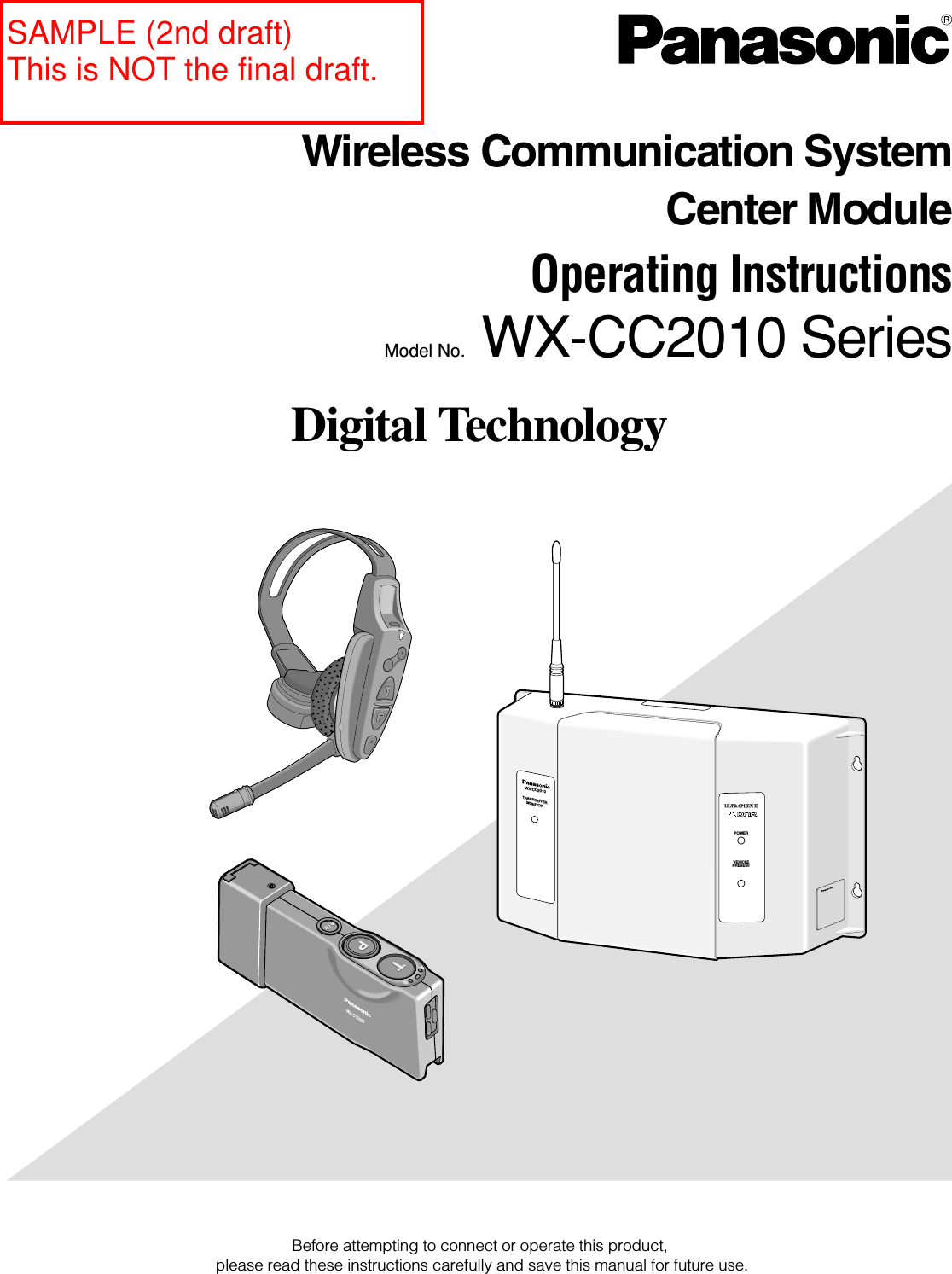
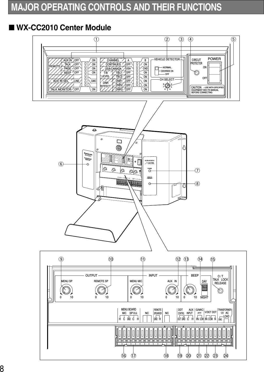
Panasonic of North America 9TAWX-CC2010Z Wireless Communication System Center Module User Manual THIS IS NOT THE FINAL DRAFT

Panasonic Corporation of North America Wireless Communication System Center Module THIS IS NOT THE FINAL DRAFT

Users Manual

Before attempting to connect or operate this product,please read these instructions carefully and save this manual for future use.Digital TechnologyWX-CC2010TRANSCEIVERMONITORPOWERVEHICLEPRESENTABWX-CT2020Model No. WX-CC2010 SeriesWireless Communication SystemCenter ModuleOperating InstructionsSAMPLE (2nd draft)This is NOT the final draft.
3IMPORTANT SAFETY INSTRUCTIONS1) Read these instructions.2) Keep these instructions.3) Heed all warnings.4) Follow all instructions.5) Do not use this apparatus near water.6) Clean only with dry cloth.7) Do not block any ventilation openings. Install in accordance with the manufacturer's instructions.8) Do not use near any heat sources such as radiators, heat registers, stoves, or other apparatus (including amplifiers) thatproduce heat.9) Do not defeat the safety purpose of the polarized or grounding-type plug. A polarized plug has two blades with one widerthan the other. A grounding-type plug has two blades and a third grounding prong. The wide blade or the third prong areprovided for your safety. If the provided plug does not fit into your outlet, consult an electrician for replacement of theobsolete outlet.10) Protect the power cord from being walked on or pinched particularly at plugs, convenience receptacles and the pointswhere they exit from the apparatus.11) Only use attachments/accessories specified by the manufacturer.12) Use only with the cart, stand, tripod, bracket, or table specified by the manufacturer, or sold with the apparatus. When acart is used, use caution when moving the cart/apparatus combination to avoid injury from tip-overs.13) Unplug this apparatus during lightning storms or when unused for long periods of time.14) Refer all servicing to qualified service personnel. Servicing is required when the apparatus has been damaged in any way,such as power-supply cord or plug is damaged, liquid has been spilled or objects fallen into the apparatus, the apparatushas been exposed to rain or moisture, does not operate normally, or has been dropped.S3125A
4CONTENTSIMPORTANT SAFETY INSTRUCTIONS  ...................................................................................................... 3PREFACE..................................................................................................................................................... 5PRECAUTIONS............................................................................................................................................ 6PANASONIC WX-CC2010 SERIES SYSTEM PARTS AND ACCESSORIES ................................................ 7MAJOR OPERATING CONTROLS AND THEIR FUNCTIONS ..................................................................... 8■WX-CC2010 Center Module ................................................................................................................. 8■WX-C516 Power Transformer ............................................................................................................... 12■WX-C1027A Headset............................................................................................................................ 12■WX-C550 Speaker Microphone ............................................................................................................ 12■WX-CT2020 Order Taker Unit............................................................................................................... 13PREPARATIONS ......................................................................................................................................... 15■Installations and Connections  ............................................................................................................. 15■Battery Charge and Replacement (WX-CH2050A/WX-CT2020)  ......................................................... 15■Setup Procedures (WX-CH2050A/WX-CT2020)  .................................................................................. 15■Preparation .......................................................................................................................................... 15■Maintenance of Headpad Accessories (WX-C1027A: Non-Scheduled) ............................................. 16OPERATING PROCEDURES ....................................................................................................................... 17TROUBLESHOOTING ................................................................................................................................. 17SPECIFICATIONS........................................................................................................................................ 18
5Panasonic WX-CC2010 Center Module is designed forPanasonic Wireless Communication System, which is usedwith drive-through menu boards, etc. The system operateson UHF frequencies, and offers multi-channel flexibilitymaking use of the PLL (Phase Locked Loop) technology.FEATURES• A remote speaker can be added to the system.• The order taker unit and all-in-one headset aredesigned to facilitate the battery installation. PREFACENew Functions of the WX-CC2010(New Technological Features)• New DNR (Digital Noise Reduction)The New DNR function provides sound quality withoutnoise that accompanies digital processing. (WX-CC2010 Center Module has the sound quality of cus-tomer's voice which has been improved than that ofWX-C1011 Center Module.)• Talkback Echo EliminationDigital delay processing eliminates talkback echo fromthe order taker unit.• TBC (Talkback Automatic Level Control)Only human voice is identified in a mixed input of cus-tomer's voice and noise from the menuboard micro-phone. Then, the volume of customer's voice is com-pared with the talk volume of the order taker unit, andthe talkback volume level is automatically controlled.
6This center module is a sensitive device and should beregarded as such. If handled carelessly, the hazard of elec-tric shock may exist.In order to utilize the instrument to its fullest potential,please consider the following precautions.1. Handle the equipment with care. This equipment con-tains sensitive components that can be damaged byimproper handling or storage.2. Refer any servicing to qualified service personnel. Donot attempt to disassemble the center module, ordertaker unit or other units. In order to prevent electricalshock, do not remove screws or covers. There are nouser-serviceable parts inside.3. Use a dry cloth to clean the center module, order takerunit or other units if soiled or dirty. If necessary, a milddetergent may be used.4. Take immediate action if the center module or ordertaker unit becomes wet. Turn the power off and havethe unit examined by qualified service personnel. Donot expose the center module or order taker unit to rainor moisture, or attempt to operate the equipment in wetareas. Do not operate the equipment if it is wet.5. Follow normal safety precautions to avoid personalinjury.6. Properly store the order taker unit (WITH HEADSETPLUGGED IN) in the order taker unit case to preventdamage to equipment.7. Replace a missing microphone cover and ear speakercover of the headset with a new one to prevent distor-tion or loss of audio.8. Repair or replace any defective components.9. Turn off the order taker unit when not in use, in order tosave the battery life.10. When the power indicator lights up in red and a pulsingbeep tone is heard in the headset, charge battery tothe order taker unit (if using WX-CT2020 in combinationwith WX-C1027A) or all-in-one headset (if using WX-CH2050A).11. Clean the battery charger of the order taker unit or all-in-one headset in accordance with manufacturerinstructions at least once a month. (Refer to the operat-ing instructions of the battery charger.)12. Perform regular preventive maintenance by testingaccessories (headset and batteries, etc.)PRECAUTIONS
7PANASONIC WX-CC2010 SERIES SYSTEM PARTS AND ACCESSORIES■All in One HeadsetWX-CH2050A■Order Taker UnitWX-CT2020■Order Taker Unit CaseWX-CT2022■Speaker MicrophoneWX-C550■Battery ChargerFor WX-CH2050A: 2050CHFor WX-CT2020: 2020CH■Vehicle Detector 917-1(Locally Procured)■Rechargeable BatteryFor WX-CH2050A: 2050BAT or 2051BATFor WX-CT2020: 2020BAT■Speaker/Loop Cable KitWX-C688ABWX-CT2020WX-CC2010TRANSCEIVERMONITORPOWERVEHICLEPRESENTConditioningConditionChargingReadyFullConditioningConditionChargingReadyFullConditioningConditionChargingReadyFullConditioningConditionChargingReadyFull■Center ModuleWX-CC2010■HeadsetWX-C1027A■Power TransformerWX-C516Note: Illustrations may differ from actual products.
8MAJOR OPERATING CONTROLS AND THEIR FUNCTIONS■WX-CC2010 Center ModuleWX-CC2010TRANSCEIVERMONITORULTRAPEX  IIPOWERVEHICLEPRESENTDNRABPOWERVEHICLEPRESENToy!0 !1 !2 !3 !4 !5uiq w rtOFFOFFOFFOFFLINEOFFONONONONG/MICONREMOTEAUX IN SELTALK MONITORAUX INTALKPAG EBEEPAOFFUSAOFFOFFOFFOFFOFFBONCNDONONONONONCHANNELCONTINUESUSA/CANADAT/BLEVELDNREFFECTTBC1TBC2DNR1DNR2DNR3VEHICLE DETECTORCH SELECTNORMALOFFOVERRIDE ON12345678POWERONOFFCAUTIONUSE WITH SPECIFIEDEQUIPMENT SEE ITS MANUALBEFORE CONNECTINGCIRCUTPROTECTORO / TTALK   LOCKRELEASEOUTPUT010 010MENU SP REMOTE SPINPUT BEEP010 010010MENU MICREMOTESPEARKERDDTCONTROLAUXAUX   INDAYLOADNIGHTHHCCGNDMENU BOARDMICSP 8 ΩNC NCHCGNDHG/MICPTTTRANSFORMER12V ACV/DET DDTINCOMOUT GNDGNDINCOMININPUTe!6 !7 !8 !9 @0 @1 @2 @3 @4
9Notes:• The following switches and terminals should be usedby qualified service personnel or system installersonly.• To change the setting of the following switches, turnoff the power of the center module, then turn it backon.qAuxiliary Input On/Off Switch (REMOTE AUX IN,ON/OFF)Set this switch to ON to output the audio (that hasbeen input from the AUX INPUT terminals) to theREMOTE SPEAKER terminals.Talk On/Off Switch (REMOTE TALK, ON/OFF)To monitor the conversation between the store person-nel and customer with the remote speaker, set thisswitch to ON.Page On/Off Switch (REMOTE PAGE, ON/OFF)To monitor the conversation among the store person-nel with the remote speaker, set this switch to ON.Beep On/Off Switch (REMOTE BEEP, ON/OFF)Set this switch to ON to output beep sounds to theremote speakers.Auxiliary Input Selection Switch(AUX IN SEL, G MIC/LINE)Note: "G MIC" is marked as "G/MIC" on the switchpanel.This switch selects the auxiliary input level.G MIC (Gooseneck Microphone)This can be used as a wired system.Input : –62 dBV, balancedLINEInput : –20 dBV, balancedTalk Monitor On/Off Switch (TALK MONITOR,ON/OFF)This switch should be normally set to OFF.Consult your servicing dealer before attempting tochange this switch.Channel Selection Switch (CHANNEL, A/B)This switch selects the frequency between channel Aand B licensed by the FCC. This switch is normally setto A. The switch can be set to B if external interferenceoccurs.Continuous Transmission On/Off Switch (CONTIN-UES, ON/OFF)ON: When the switch is set to ON, the transmissionstarts by turning on the power of center module.OFF: When the switch is set to OFF, the transmissionstarts with the following conditions.• The VEHICLE DETECTOR switch has beenset to NORMAL or OVERRIDE ON.• The button P or T on the order taker unit hasbeen pressed. USA/Canada Switch (USA/CANADA, USA/CND)To select a radio frequency suitable for the region, setthis switch as follows.USA: This setting is available in the United States.CND: This setting is available in Canada.Talkback Level Control Switch (T/B LEVEL: TBC1,TBC2, ON/OFF)These switches are used for the talkback level settingof the order taker unit.Change the settings if the talkback level is too high.Note: These settings are activated when the DNRswitch is set to ON.DNR (Digital Noise Reduction) Effect Level ControlSwitch(DNR EFFECT: DNR1, DNR2, DNR3, ON/OFF)These switches are used for the noise reduction levelsetting.The more the noise is reduced, the lower the soundquality will be. The following table shows the relation-ship between noise reduction level and sound quality.Note: No setting should be done other than shown inthe table.Setting TalkbackLevelTBC1TBC2TBC1TBC2TBC1TBC2TBC1TBC2Normally set to this position.Talkback level set to 50 %.Talkback level set to 35 %.Talkback level set to 25 %.Remarks–6 dB–9 dB–12 dB– Talkback is off.SettingNoise ReductionLevelDNR1DNR2DNR3DNR1DNR2DNR3DNR1DNR2DNR3DNR1DNR2DNR3No DNR processingFor a relatively quiet environmentRemarksSoundQualityHighNormalLowLowNormalHighFor a very noisy environmentNot recommended because it affects sound quality.For a general environmentThis setting is recommen-ded.
10iVehicle Detector Indicator (VEHICLE PRESENT)(Amber)This indicates that a vehicle has been detected. oMenuboard Speaker Volume Control(MENU SP, 0 to 10)This control sets the output level of MenuboardSpeaker to the optimum level for speaking to the cus-tomer.Notes:• Adjust this control after you set the VEHICLEDETECTOR switch to OVERRIDE ON and the vehi-cle detector indicator lights up. Otherwise, youcannot adjust the volume level.• The line marked on this control is a standard posi-tion for this adjustment. Adjust this control to thesuitable position so that feedback does not occur.!0 Remote Speaker Volume Control(REMOTE SP, 0 to 10)This control sets the output level of Remote Speaker tothe optimum level.Notes:• Adjust this control after you set the VEHICLEDETECTOR switch to OVERRIDE ON and the vehi-cle detector indicator lights up. Otherwise, youcannot adjust the volume level.• The line marked on this control is a standard posi-tion for this adjustment.Adjust this control to the suitable position so thatfeedback does not occur. !1 Menuboard Microphone Volume Control(MENU MIC, 0 to 10)This control sets the input level of MenuboardMicrophone to the optimum level.Notes:• Adjust this control after setting the VEHICLEDETECTOR switch to OVERRIDE ON and the vehi-cle detector indicator lights up. Otherwise, youcannot adjust the volume level.• The line marked on this control is a standard posi-tion for this adjustment. Adjust this control to thesuitable position so that feedback does not occur.!2 Auxiliary Input Level Control (AUX IN, 0 to 10)This controls the input level of the AUX INPUT termi-nals.!3 Vehicle Detector Beep Volume Control(BEEP, 0 to 10)This control sets the vehicle-detection beep tone for theorder taker unit to the optimum level. When the VEHI-CLE DETECTOR switch is set to NORMAL, turning thiscontrol changes the beep tone level of the remotespeaker.wVehicle Detector Normal/Override On/Off Switches(VEHICLE DETECTOR, NORMAL/OVERRIDEON/OFF)NORMAL: The vehicle detector turns on only when avehicle is detected at the menu board. When thedetector is turned on, a beep tone is heard in theheadset. After the beep tone, the menuboardspeaker turns on to allow the communication withthe customer. When the vehicle leaves, the vehicledetector turns off.OVERRIDE ON: The vehicle detector is always turnedon.OFF: Vehicles are not detected at the menuboard. Nobeep tone is heard in the headset, and themenuboard speaker remains off.eChannel Group Selection Switch(CH SELECT, 1 to 8)This switch selects the group from 8 positions.Note: Do not set this switch to positions other than 1 to8. That will result in an error.rCircuit Protector button (CIRCUIT PROTECTOR)If excessive current flows to the center module, the cir-cuit protector is triggered. When this button is stickingout, turn off the POWER switch, press this CIRCUITPROTECTOR button, and turn on the POWER switchagain.If the circuit protector is soon triggered again, consultyour dealer or authorized service center for assistance.tPower On/Off Switch (POWER, ON/OFF)This switch turns the power of the center module onand off.Channel MonitorChannel Monitor is the mode to check if other deviceshave already used the desired channel at the time ofthe installation. The following is how to activate ChannelMonitor.When you set the POWER switch to ON while holdingdown the O/T TALK LOCK RELEASE switch, ChannelMonitor is activated. To return to the default mode, turnoff and on the power again with the POWER switch. yTalk/Page Indicator (TRANSCEIVER MONITOR, Red/Green/Amber)Red: When the order taker unit is in the Talk PTT/TalkLock mode, the indicator lights up in red.Green: When the order taker unit is in the Page PTT/Page Lock mode, the indicator lights up in green.Amber: When the gooseneck microphone is enabled,the indicator lights up in amber.uPower Indicator (POWER) (Green)This indicates that the power of center module is on.
Night mode11!4 Day/Night Selection Switch (DAY/NIGHT)In the Day mode, you will not hear the beep tone of theother lane in the headset that sounds when the vehicledetector is on and that sounds when you press the but-ton T of the order taker unit.In the Night mode, you will hear the beep tone of eitherlane in the headset when the vehicle detector of eitherlane is on. Once you press the button T, you will nolonger hear your lane’s beep tone. However, you willcontinue to hear the other side’s beep tone when theother side vehicle detector is on, until the button T ofthe other side’s order taker unit is pressed.Note: The following is the beep patterns.Beep A: Pi...Pi...Beep B: PiPi...PiPi...Beep C: Pi..PiPi...Pi..PiPi...State of laneVehicle detec-tor at Lane A isON.Vehicle detec-tor at Lane B isON.A Beep AOrdertaker unitBeep ABBeep A Beep AABeep B Beep BB Beep B Beep BVehicle detec-tors of bothlanes are ON.A Beep C(When you pressthe button T, thebeep tone will bedeactivated.)Beep C(When youpress thebutton T,Beep C willchange toBeep B.BBeep C(When you pressthe button T, thebeep tone will beactivated.)Beep C(When youpress thebutton T,Beep C willchange toBeep A.!8 Remote Speaker Terminals(REMOTE SPEAKER: H, GND)These terminals are used for the connection withRemote Speaker.The audio level is 8 Ω, 3 W, unbalanced.Note: The remote speaker is a locally procured acces-sory.!9 Double Drive Through Control Output Terminals (DDT CONTROL: OUT, GND)To compose Double Drive Through of two center mod-ules, these terminals are used for the connection withthe DDT (IN, COM) terminals of the other center mod-ule.• The DDT CONTROL OUT terminal is connectedwith the DDT IN terminal of the other center mod-ule.• The DDT CONTROL GND terminal is connectedwith the DDT COM terminal of the other centermodule.@0 Auxiliary Input Terminals (AUX INPUT: H, C, GND)These terminals are used for the connection with theline or the connection with a gooseneck microphone.Note: When connecting the gooseneck microphone,set the AUX IN SEL switch to G/MIC.@1 Gooseneck Microphone PTT Terminals(G/MIC PTT: IN, COM)These terminals are used for the connection with thePTT cable of a gooseneck microphone (locally pro-cured).@2 Vehicle Detector Terminals(V/DET: IN, COM)These terminals are used for the connection with theoutput terminal of vehicle detector.@3 Double Drive Through Control Input Terminals(DDT: IN, COM)To compose Double Drive Through of two center mod-ules, these terminals are used for the connection withthe DDT CONTROL (OUT, GND) terminals of the othercenter module.• The DDT IN terminal is connected with the DDTCONTROL OUT terminal of the other center mod-ule.• The DDT COM terminal is connected with the DDTCONTROL GND terminal of the other center mod-ule.@4 Transformer Terminals(TRANSFORMER 12V AC: GND, LOAD)These terminals are used for the connection with WX-C516 Power Transformer.!5 Order Taker Unit Talk Lock Release Switch(O/T TALK LOCK RELEASE)This switch is used to release temporarily the talk lockmode of the order taker unit.!6 Menuboard Microphone Terminals(MENU BOARD MIC: H, C, GND)These terminals are used for the connection withMenuboard Microphone (Speaker Microphone WX-C550).The audio level is –61 dBV, 8 Ω, balanced.!7 Menuboard Speaker Terminals(MENU BOARD SP 8 Ω: H, C, GND)These terminals are used for the connection withMenuboard Speaker (Speaker Microphone WX-C550).The audio level is 8 Ω, 3 W, unbalanced.Day mode
12■WX-C516 Power Transformer#3 Mounting Hole This hole is used for mounting the power transformeronto the wall plates.#4 Power PlugTo prevent fire or electrical shock, connect this directlyto a 3-plug grounded receptacle of 120 V AC, 60Hz.#5 Output terminal (SPARE, AC, AC, GND)12 V AC, 1 600 mA (UL Listed) is provided at the twoterminals (indicated as "AC") to be used for the centermodule.Caution:Be sure to connect the wire between the GND(GROUND) of this terminal and that in the trans-former terminal on the center module.To prevent fire or electrical shock, the UL listedpower supply cord (Style SVT) should be used forthe cable for 12 V AC terminal.■WX-C1027A Headset#6 Earphone#7 Microphone#8 Cable ClipsUse these clips to attach the cable to your uniform.#9 Headset Plug■WX-C550 Speaker Microphone$0$1#3#4#5#6#7#8#9$0 Input Cord A pigtail cord is provided for the speaker input. Itslength is approx. 3 meters.$1 Mounting BracketAU-type mounting bracket with screw holes is provid-ed as a standard accessory with the WX-C550.
13■WX-CT2020 Order Taker UnitEJECTWX-CT2020ABPWRVOL$8 $9%3%0 %1%2 $2$7$2 $3 $4 $5 $6
14$2 Battery Lock (EJECT)$3 A/B Channel Selection Button (A/B)$4 Page Button (P)$5 Talk Button (T)$6 Power Indicator$7 Channel Indicator$8 Volume Control Buttons (VOL AB)$9 Power Button%0 Earphone Input Jack%1 Microphone Input Jack%2 Switch Pocket%3 Battery (Optional accessory)
15■Installations and ConnectionsRefer to qualified service personnel for details.■Battery Charge and Replacement(WX-CH2050A/WX-CT2020)Refer to WX-CT2020/WX-CH2050A Operating Instructionsfor details.■Setup Procedures(WX-CH2050A/WX-CT2020)Note: Setup of WX-CC2010 should only be performed byqualified service personnel or system installers. ●Opening the Switch Pocket Refer to WX-CT2020/WX-CH2050A Operating Instructionsfor details.●Channel Group SelectionRefer to p. 18 for the frequency table.OFF: The person is assigned as assistant personnel.●DIP Switch SetupRefer to WX-CT2020/WX-CH2050A Operating Instructionsfor details.●Channel Interference CheckRefer to WX-CT2020/WX-CH2050A Operating Instructionsfor details.■PreparationNote: The following procedure applies when using WX-CT2020 Order Taker Unit and WX-C1027A Headset. Ifyou use WX-CH2050A All-in-One Headset, refer to theoperating instructions of the headset.1. After loading a battery into the order taker unit, insertthe headset plug into the earphone input jack andmicrophone input jack on the order taker unit.Note: Confirm that the plug has completely beeninserted into the jack.2. Position the microphone boom and wear the ordertaker unit case as shown in the figure.PREPARATIONS
16■Maintenance of HeadpadAccessories (WX-C1027A: Non-Scheduled)Notes:• The following procedure applies when using WX-C1027A Headset. If you use WX-CT2020 Order TakerUnit, refer to the operating instructions of the headset.• Be sure to use the microphone cover/windproof cush-ion for WX-C1027A Headset. Otherwise, the headsetmay be damaged by dust or oil.Replacement of covers and cushion of head-setThe earspeaker cover and microphone cover arewashable. After cleaning, make sure they are dry.Then, return the earspeaker cover and microphonecover to the headset.Be careful when you slip it on or off the earpiece.The earspeaker cover, microphone cover and head-pad cushion are replaceable for sanitary purposes. Toorder WX-C1025A Headset Cover Kit, refer to the deal-er.Note: A microphone cover must be used at all times.Failure to do so can cause debris to accumulate inthe microphone port opening and result in an inop-erative headset.Headpad Cushion Replacement1. Peel off the old cushion.2. Clean the surface with a warm solution of house-hold cleaner.3. Remove the protective tape from the new cushion.4. Position the new cushion on the headpad andpress in place.Microphone Cover ReplacementEarspeaker Cover ReplacementHeadpad Cushion Replacement
Problem17Refer to WX-CT2020/WX-CH2050A Operating Instructions for details.OPERATING PROCEDURESCheck itemTROUBLESHOOTINGThe communication between the order taker units and menuboard cannot be established. (The TRANSCEIVER MONITORindicator is not blinking in red.)The communication between the order taker units and menuboard cannot be established. (The TRANSCEIVER MONITORindicator is blinking in red.)• Is the POWER switch on the center module turned on?(Refer to p. 10.)• Check the AC power outlet.• Push the CIRCUIT PROTECTOR button. (Refer to p. 10.)• Refer to the dealer or qualified service personnel.• Is the CH SELECT switch set to 1 to 8?• If the problem remains even after trying the above, refer tothe dealer or service personnel. (Refer to p. 10.)• Check to see if the VEHICLE PRESENT indicator of the cen-ter module lights up when a vehicle drives up the speakerpost or menu board. • If the indicator does not light up, check the following.1. Is the vehicle detector plugged in?2. Check the AC outlet and fuse of the vehicle detector.If the power and fuse are normal, refer to the qualified ser-vice personnel.• Reset the vehicle detector. If the problem still remains,remove and reinstall the fuse from the detector. (Refer to theoperating instructions of the vehicle detector.)• If the problem remains even after trying the above, refer tothe dealer or service personnel.• Confirm that there is no metal obstruction blocking aroundthe center module.• It may be necessary to extend one or both antennas toareas where the reception is error. (Refer to qualified servicepersonnel or system installers.)Cannot communicate with the customer at the menu board(TALK), though the communication among personnel is O.K(PAGE is OK).A menuboard speaker is always live, even when there is nocar beside the menu board.TALK (Talk PTT or Talk Lock mode) or PAGE (Page PTT orPage Lock mode) is unavailable in certain areas.
18WX-CC2010 Center ModuleOperating Frequency: Transmit; 468.6125 MHz - 469.3875 MHzReceive; 463.6125 MHz - 464.3875 MHzType of Emission: F3Type of Antenna: 1/4 wavelength whip antenna Power Supply: 12 V AC, 60 Hz (Using WX-C516 Power Transformer)Power Consumption: 10 WMenuboard Speaker A and B Output: 3 W, 8 ΩRemote Speaker A and B Output: 3 W, 8 ΩVehicle Detector Input: Normally Open (close contact requires vehicle presence)Dimensions: 330 mm (W) X 214 mm (H) X 82 mm (D){13 in. (W) X 8-7/16 in. (H) X 3-15/64 in. (D)}Weight (Including Antenna): 1.6 kg(3.5 lbs.)Ambient operating temperature: –10 °C to +50 °C {14 °F to 122 °F}Dimensions and weights indicated are approximate.Specifications are subject to change without notice.Frequency tableSPECIFICATIONSCANADAUSA463.6125MHz463.6375MHz463.6625MHz463.6875MHz463.7125MHz463.7375MHz463.7625MHz463.7875MHz463.8125MHz463.8375MHz463.8625MHz463.8875MHz463.9125MHz463.9375MHz463.9625MHz463.9875MHz464.0125MHz464.0375MHz464.0625MHz464.0875MHz464.1125MHz464.1375MHz464.1625MHz464.1875MHz464.2125MHz464.2375MHz464.2625MHz464.2875MHz464.3125MHz464.3375MHz464.3625MHz464.3875MHzCM: Receive Freq.OT: Transmit Freq.468.6125MHz468.6375MHz468.6625MHz468.6875MHz468.7125MHz468.7375MHz468.7625MHz468.7875MHz468.8125MHz468.8375MHz468.8625MHz468.8875MHz468.9125MHz468.9375MHz468.9625MHz468.9875MHz469.0125MHz469.0375MHz469.0625MHz469.0875MHz469.1125MHz469.1375MHz469.1625MHz469.1875MHz469.2125MHz469.2375MHz469.2625MHz469.2875MHz469.3125MHz469.3375MHz469.3625MHz469.3875MHzCM: Transmit Freq.OT: Receive Freq.G1Frequency GroupABG2ABG3ABG4ABG5ABG6ABG7ABG8ABAG1Frequency GroupBG2ABG3ABG4ABG5ABG6ABG7ABG8ABCM:Center Module (WX-CC2010)OT:Order Taker Unit (WX-CT2020 or WX-CH2050A)
NM0703-2104 3TR001757CAA Printed in JapanPANASONIC CANADA INC.5770 Ambler Drive, Mississauga, Ontario, L4W 2T3 Canada (905)624-5010PANASONIC SALES COMPANYDIVISION OF MATSUSHITA ELECTRIC OF PUERTO RICO INC.San Gabriel Industrial Park 65th Infantry Ave. KM. 9.5 Carolina, P.R. 00985 (809)750-4300Panasonic Digital Communications & Security CompanyUnit of Matsushita Electric Corporation of AmericaSecurity Systems Groupwww.panasonic.com/cctvExecutive Office: One Panasonic Way 3E-7, Secaucus, New Jersey 07094Zone OfficeEastern: One Panasonic Way, Secaucus, NJ 07094 (201) 348-7303Central: 1707 N.Randal Road, Elgin, IL 60123 (847) 468-5205Western: 6550 Katella Ave., Cypress, CA 90630 (714) 373-78402004 © Matsushita Electric Industrial Co., Ltd.  All rights reserved.

Navigation menu