Panasonic of North America 9TAWX-CC412 DECT 6.0 Center Module (with 2 Wireless modules) User Manual
Panasonic Corporation of North America DECT 6.0 Center Module (with 2 Wireless modules)
UserManual.wiki
>
Panasonic of North America
>
9TAWX CC412 User Manual
Users Manual
Navigation menu
Upload a User Manual
Namespaces
Wiki Guide
HTML
PDF
Info
Views
User Manual
Discussion / Help
Navigation
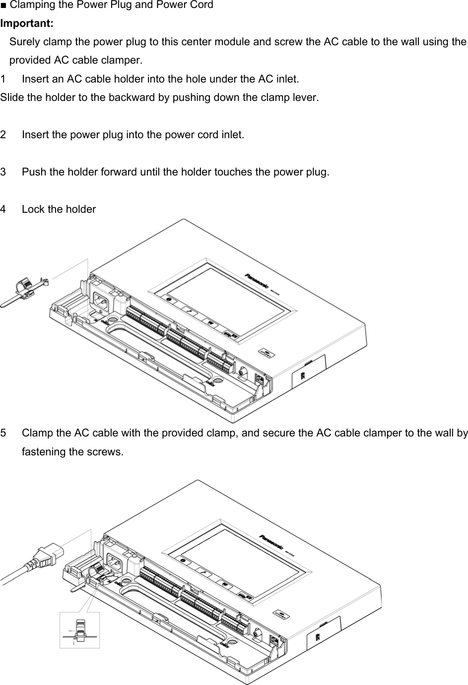
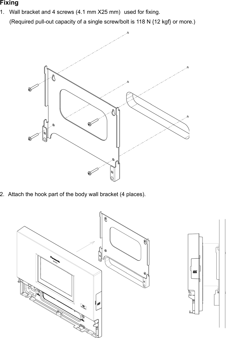
![■ Installation procedures Preparations (Refer to page xx.) Installation of center modules on the wall (Refer to page xx.) Wiring to the center modules (Refer to page xx.) ID registration for follower units (Refer to page xx.) [System Setup] Installed System Setting (Refer to page xx.) Adjustments to adequate sound levels Preparations This Center Module is designed to be mounted on a wall via wall bracket. Please be advised of the following: - Procure 4 mounting screws according to the material of the installation area. In this case, wood screws and nails should not be used. Recommended screw: M4 x 25 mm - Required pull-out capacity of a single screw/bolt is 118 N {12 kgf} or more. - If a wall board is too weak to support the total weight, the area shall be sufficiently reinforced. How to instillation Determination of the mounting position Open the hole for connection wires, and determine the screw mounting position of the four locations as the figure below. (Unit: mm)](https://usermanual.wiki/Panasonic-of-North-America/9TAWX-CC412/User-Guide-2119377-Page-24.png)
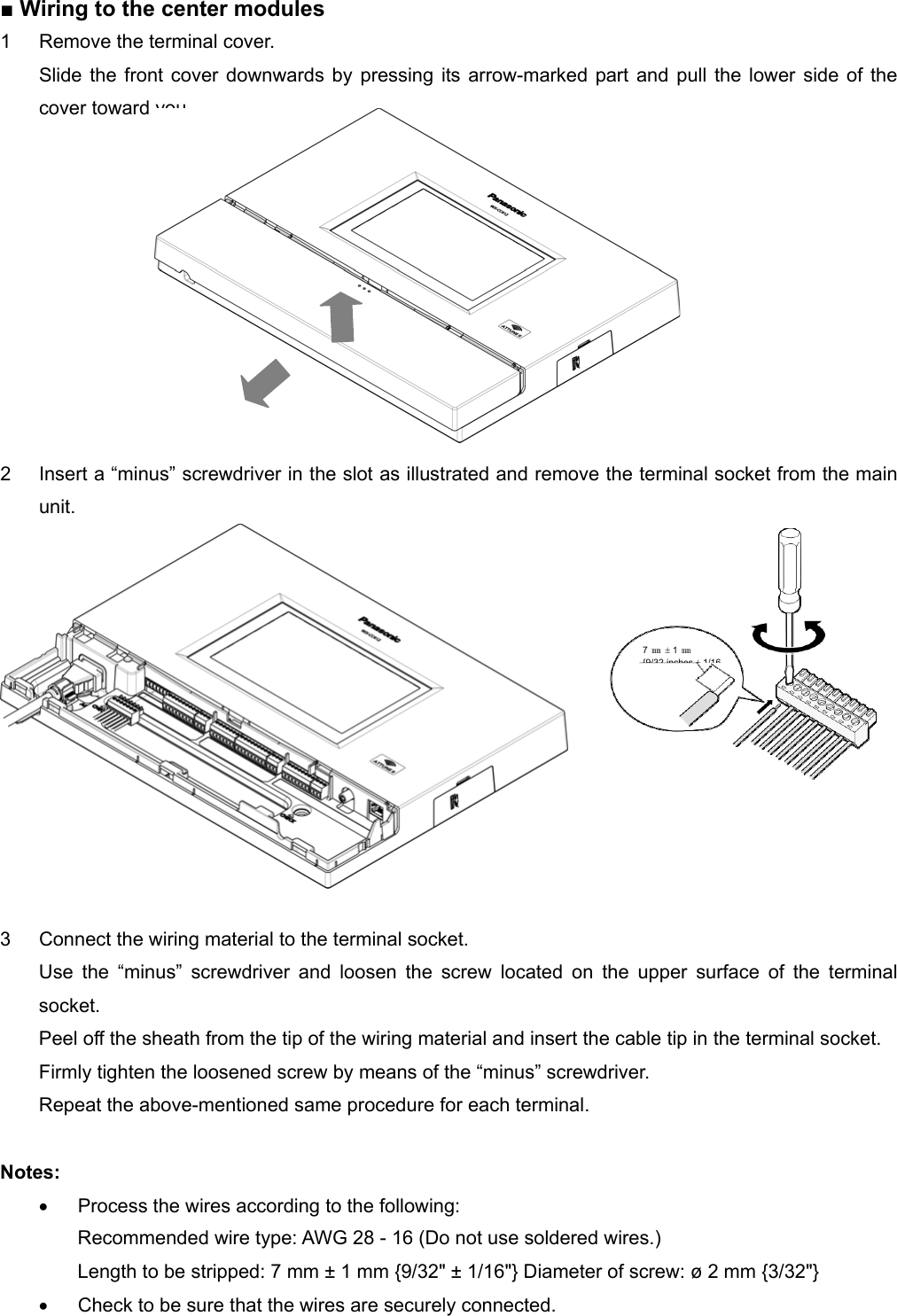
![3. Make sure that the body is stuck completely through confirmation window [CHECK] If you can visually stamp completely, it is properly installed. Stamp is not visible, or if you are missing, it is not installed correctly. If possible visibility, it is installed correctly. 4. Using the wall fixing clamp the supplied power cord and mounting (25 mm 4.1 mm ×) screws provided. [Minimum pull-out strength 780 N {80 kgf}] 150 ㎜~200 ㎜](https://usermanual.wiki/Panasonic-of-North-America/9TAWX-CC412/User-Guide-2119377-Page-26.png)