Panasonic of North America 9TAWX-CC412 DECT 6.0 Center Module (with 2 Wireless modules) User Manual
Panasonic Corporation of North America DECT 6.0 Center Module (with 2 Wireless modules)
Users Manual
Center Module
Operating Instructions
Model No.
WX-CC411
WX-CC412
ENGLISH
FRANÇAIS
ENGLISH VERSION
This device complies with Part 15 of FCC Rules and Industry Canada licence-exempt RSS standard(s). Operation is
subject to the following two conditions: (1) this device may not cause interference, and (2) this device must accept any
interference, including interference that may cause undesired operation of this device.
This equipment complies with FCC/IC radiation exposure limits set forth for an uncontrolled environment and meets the
FCC radio frequency (RF) Exposure Guidelines in Supplement C to OET65 and RSS-102 of the IC radio frequency
(RF) Exposure rules. This equipment should be installed and operated keeping the radiator at least 20cm or more away
from person’s body (excluding extremities: hands, wrists, feet and ankles).
This transmitter must not be co-located or operated in conjunction with any other antenna or transmitter.
Changes or modifications not expressly approved by the party responsible for compliance could void the user’s
authority to operate the equipment.
This equipment has been tested and found to comply with the limits for a Class A digital device, pursuant to part 15 of
the FCC Rules. These limits are designed to provide reasonable protection against harmful interference when the
equipment is operated in a commercial environment. This equipment generates, uses, and can radiate radio frequency
energy and, if not installed and used in accordance with the instruction manual, may cause harmful interference to
radio communications. Operation of this equipment in a residential area is likely to cause harmful interference in which
case the user will be required to correct the interference at his own expense.
FEDERAL COMMUNICATIONS COMMISSION INTERFERENCE STATEMENT
WARNING:
• This apparatus must be earthed.
• Apparatus shall be connected to a main socket outlet
with a protective earthing connection.
• The mains plug or an appliance coupler shall remain
readily operable.
• To reduce the risk of fire or electric shock, do not
expose this apparatus to rain or moisture.
• The apparatus should not be exposed to dripping or
splashing and that no objects filled with liquids, such
as vases, should be placed on the apparatus.
• All work related to the installation of this product
should be made by qualified service personnel or
system installers.
• To prevent injury, this apparatus must be securely
attached to the floor/wall in accordance with the
installation instructions.
• The connections should comply with local electrical
code.
• The risk of hearing impairment due to exposure to
excessive sound levels may be reduced by listening at
lower volumes and for shorter durations.
・Operating near 2.4 GHz electrical appliances may
cause interference. Move away from the electrical
appliances.
・This transmitter must not be co-located or operated in
conjunction with any other antenna or transmitter.
・MEDICAL:
Consult the manufacturer of any personal medical
devices, such as pacemakers, to determine if they are
adequately shielded from external RF (radio
frequency) energy. (The unit operates in the frequency
range of 2.412 GHz to 2.462 GHz, and the power
output level is 0.1 watts.)
Do not use the unit in health care facilities if any
regulations posted in the area instruct you not to do so.
Hospitals or health care facilities may be using
equipment that could be sensitive to external RF (radio
frequency) energy.
• The installation shall be carried out in accordance with
all applicable installation rules.
・To prevent fire or electric shock hazard, do not expose
this apparatus to rain or moisture.
CAUTION:
The FCC ID number for this radio equipment is listed below.
FCC ID: ACJ9TAWX-CC411
FCC ID: ACJ9TAWX-CC412
ICES-003
CAN ICES-3(A)/NMB-3(A)
CAUTION:
• Danger of explosion if battery is incorrectly replaced.
Replace only with the same or equivalent type.
• These servicing instructions are for use by qualified
service personnel only. To reduce the risk of electric
shock do not perform any servicing other than that
contained in the operating instructions unless you are
qualified to do so.
・Any changes or modifications not expressly approved
by the party responsible for compliance could void the
user’s authority to operate the equipment.
・Shielded (STP) LAN cables must be used with this unit
to ensure compliance with EMC standards.
RSS-Gen
• Under Industry Canada regulations, this radio
transmitter may only operate using an antenna of a
type and maximum (or lesser) gain approved for the
transmitter by Industry Canada. To reduce potential
radio interference to other users, the antenna type and
its gain should be so chosen that the equivalent
isotropically radiated power (e.i.r.p.) is not more than
that necessary for successful communication.
A
lithium-ion battery that is recyclable powers
the product you have purchased. Please call
1-800-8-BATTERY for information on how to
recycle this battery.
For U.S.A.
For Canada.
For Canada.
This product contains a CR Coin Cell Lithium Battery
which contains Perchlorate Material – special handling
may apply.See
www.dtsc.ca/gov/hazardouswaste/perchlorate/
For U.S.A.
Important Safety Instructions
1) Read these instructions.
2) Keep these instructions.
3) Heed all warnings.
4) Follow all instructions.
5) Do not use this apparatus near water.
6) Clean only with dry cloth.
7) Do not install near any heat sources such as radiators, heat registers, stoves, or other apparatus (including
amplifiers) that produce heat.
8) Do not defeat the safety purpose of the polarized or grounding-type plug. A polarized plug has two blades
with one wider than the other. A grounding type plug has two blades and a third grounding prong. The wide
blade or the third prong are provided for your safety. If the provided plug does not fit into your outlet, consult
an electrician for replacement of the obsolete outlet.
9) Protect the power cord from being walked on or pinched particularly at plugs, convenience receptacles, and
the point where they exit from the apparatus.
10) Only use attachments/accessories specified by the manufacturer.
11) Use only with the cart, stand, tripod, bracket, or table specified by the manufacturer, or sold with the
apparatus. When a cart is used, use caution when moving the cart/apparatus combination to avoid injury
from tip-over.
12) Unplug this apparatus during lightning storms or when unused for long periods of time.
13) Refer all servicing to qualified service personnel. Servicing is required when the apparatus has been
damaged in any way, such as power-supply cord or plug is damaged, liquid has been spilled or objects
have fallen into the apparatus, the apparatus has been exposed to rain or moisture, does not operate
normally, or has been dropped
(1) Product outline
Preface
Center Module WX-CC411, WX-CC412 is exclusively designed for Panasonic Wireless Communication
System, which is used with drive-thru menu boards, etc. The system operates on 1.9 GHz DECT.
Features
- Center Module WX-CC411, CC412 provides the central control function to DWCS.
- They are used at Drive-Through Restaurants: WX-CC411 for single lane, and WX-CC412 for dual lane.
- 1.9GHz DECT Technology provides high stable communication with wider coverage area, higher speech
intelligibility and little interference.
- Strong Echo canceller and Digital Noise Reduction (DNR) provide higher speech intelligibility.
- Wall mount enclosure allows lower and easier installation.
- A center module can register up to 32 portable units. Four people can talk at the same time per lane.
- 7 inch Color LCD with touch panel provides easy operation.
- IP Network connection (via Ethernet) provides remote operation capability.
- Using SD card, it’s possible to Backup and Restore settings. In addition, the restaurant’s own messages can
be saved.
- Built-in scheduler can replace greeter messages at a specified time, and it can also play reminder messages
automatically.
- Panasonic IP cameras can be registered up to 4 units, and their videos can be checked with the LCD of
center module.
- On receiving alert signal, it’s possible to transfer alert message to the portable unit, output the signal to
external devices, and send alert E-mail to the outside of the store as well.
Precautions
Handle this product with care. The product contains sensitive components that can be damaged by
improper handling or storage.
Repair or replace any defective components.
Use this product for indoor use only.
Do not expose this product to direct sunlight for hours and do not install the product near a heater or an air
conditioner. Otherwise, it may cause deformation, discoloration and malfunction. Keep this product away
from water.
Avoid installing in the following locations.
- Locations where a chemical agent is used such as a swimming pool
- Locations under the air conditioner
- Locations near the fryer
- Locations near the grill
- Locations in a humid or dust-laden environment
- Locations near flammable gas or vapor
- Locations where radiation or x-ray emissions are produced
- Locations subject to strong magnetic field or radio waves
- Locations where corrosive gas is produced
- Locations where it may be damaged by briny air such as seashores
- Locations subject to vibrations (This product is not designed for on-vehicle use.)
Be sure to remove this product if it is not in use.
Avoid connections during a lightning storm. Otherwise, an electric shock may be caused.
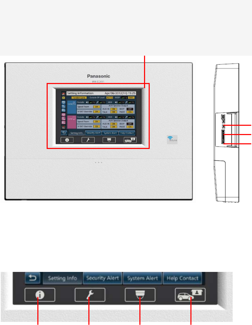
(2) Name and descriptions of each parts and basic screen
Appearance
a
b
c
(1) LCD Touch Panel
(1) 7 inch color touch panel LCD
7 inch color touch panel LCD for operation and display.
a) Reset button
b) SD Card Slot
c) SD Card Access LED
Indication for SD Card Access Status
(3) (4) (5)
(2)
(2) Information Button
Display the status and configuration
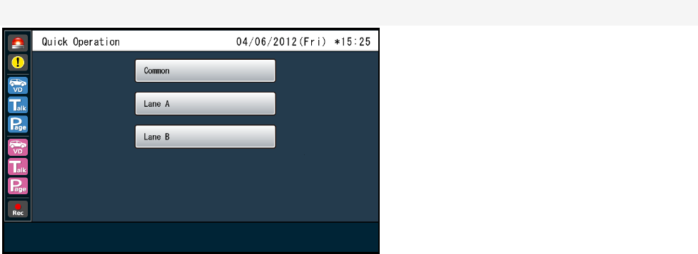
(3) Settings button
Display the various setting screens.
(4) Camera button
Display the image on the screen by the network camera that is connected to the center module.
(5) Quick button
Display the Quick Control screen to be used in the store operation.
Basic Screen
(7)
(8)
(9)
(10)
(11)
(12)
(13)
(14)
(15)
(6)
(6) Security alert indicator
If you receive an alert signal from the All-in-One Headset or an external device, it is displayed in color.
(7) Vehicle Detection indicator (Lane A)
When the vehicle came to the position of the menu board, it is displayed in color.
(8) Talking indicator (Lane A)
Store personnel and customers at lane A during the conversation, it is displayed in color.
(9) Talking indicator (Lane A)
Store personnel for lane A during the conversation with each other, it is displayed in color.
(10) Vehicle Detection indicator (Lane B)
When the vehicle came to the position of the menu board, it is displayed in color.
(11) Talking indicator (Lane B)
Store personnel and customers at lane B during the conversation, it is displayed in color.
(12) Talking indicator (Lane B)
Store personnel for lane B during the conversation with each other, it is displayed in color.
(13) REC button
During message recording, it is displayed in color.
(14) Return button
Go back to the go back to the previous screen.
(15) Page switching bar
Indicate what page of the one you have more than one page.
Go to next or previous page with up and down buttons.
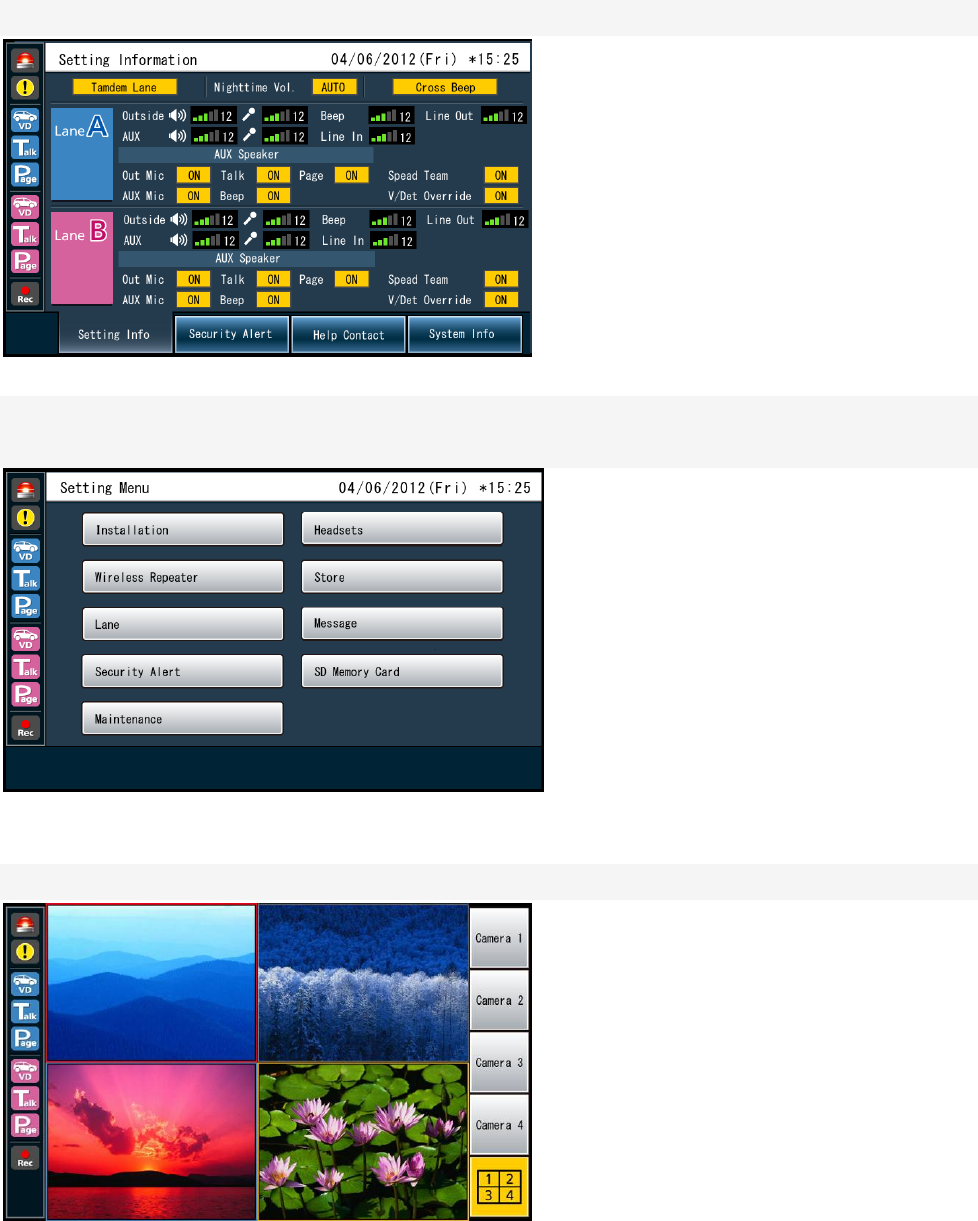
Setting Screen
(16)
(33)
(32)
(27) (29) (31)
(28) (30)
(18)
(24)(20)
(21)
(22)
(23) (19) (26) (25)
(17)
(16) Lane mode indication
Indication for Lane A or Lane B
(17) Lane indication
Indication for tandem lane or single lane
(18) Nightting volume mode indicator
Indication for the status of the speaker volume at night
(19) Cross Beep indicator
Indication for the status of the cross beep setting
(20) Outside Speaker volume level indicator (Lane A)
Indication for the sound level
(21) Outside Speaker volume level indicator (Lane A)
Indication for the sound level
(22) Mic volume level indicator (Lane A)
Indication for the sound level

(23) AUX Mic volume level indicator (Lane A)
Indication for the sound level
(24) Beep sound volume level indicator (Lane A)
Indication for the sound level
(25) Line input level indicator (Lane A)
Indication for the sound level
(26) Line output level indicator (Lane A)
Indication for the sound level
(27) Outside Mic indicator
ON/OFF indication
(28) Outside Mic indicator
ON/OFF indication
(29) Talking with customer indicator
ON/OFF indication
(30) Beep sound indicator
ON/OFF indication
(31) Talking with greeters indicator
ON/OFF indication
(32) Spead Team indicator
ON/OFF indication
(33) Vehicle detection indicator
ON/OFF indication
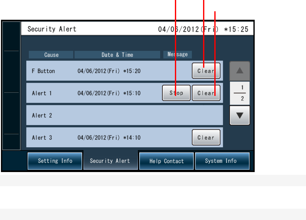
Security Alert Screen
(36) (35)
(37)
Display the date and time that the issue of security has occurred
(35) F Button/Clear button
Clear the alert
(36) Alert stop button
Stop the beep sound in the Beltpack (WX-CT420) or All-in-One Headset (WX-CH450).
(37) Alert clear button
Clear the alert
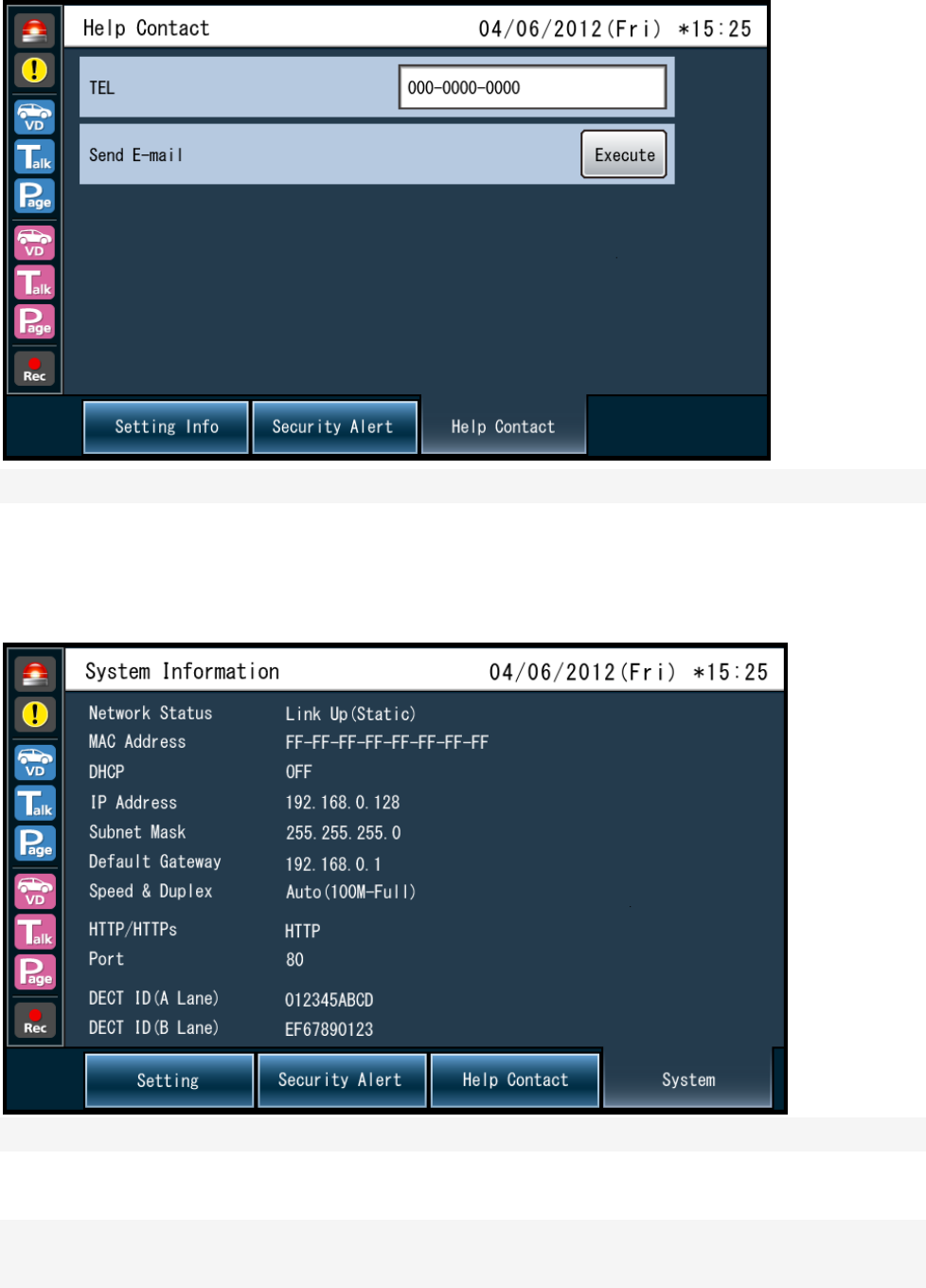
Help Contact Information Screen
Indicate the emergency contact information
System Information Screen
Indication for networking status
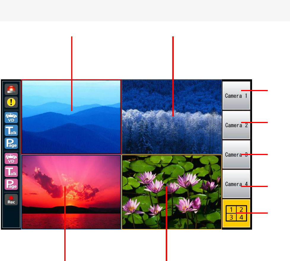
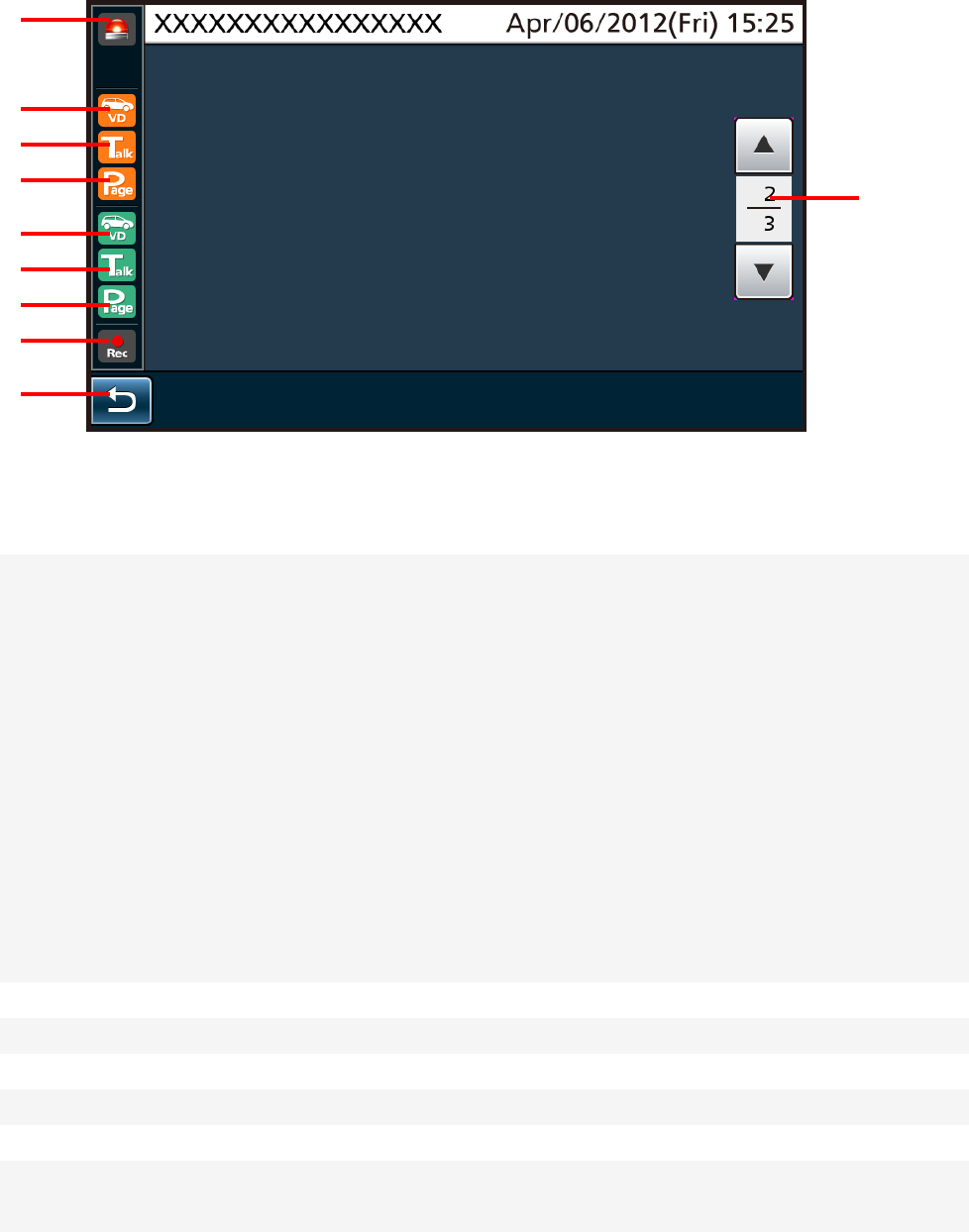
Camera monitoring screen (multi)
(44)
(43)
(42)
(45)
(46)
(41)(40)
(38) (39)
(38) Camera 1 Screen
Display the image of Camera 1
(39) Camera 2 Screen
Display the image of Camera 2
(40) Camera 3 Screen
Display the image of Camera 3
(41) Camera 4 Screen
Display the image of Camera 4
(42) Camera 1 Full Screen Button
Display on the full screen of camera 1
(43) Camera 1 Full Screen Button
Display on the full screen of camera 2
(44) Camera 3 Full Screen Button
Display on the full screen of camera 3
(45) Camera 4 Full Screen Button
Display on the full screen of camera 4
(46) 4 screen simultaneous display button
Display the image of all cameras
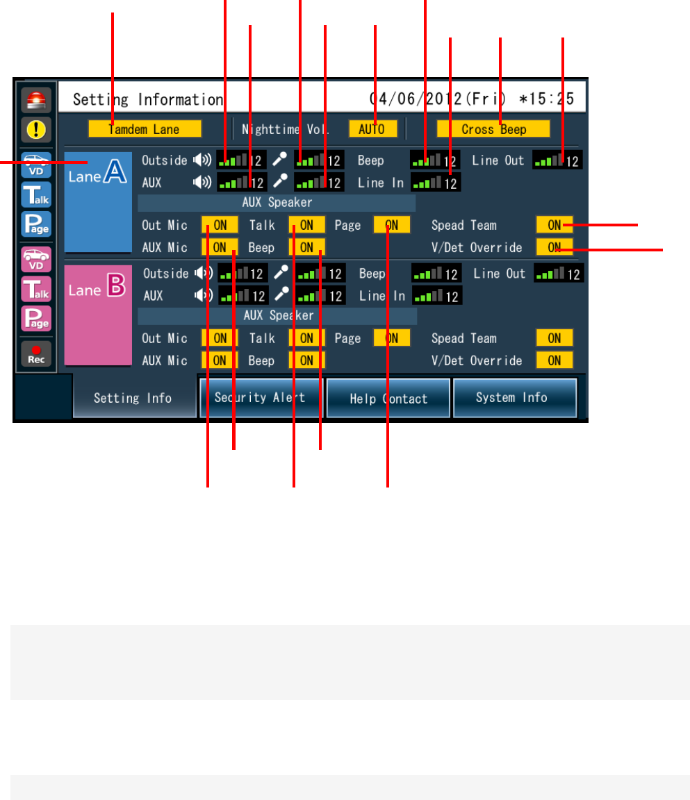
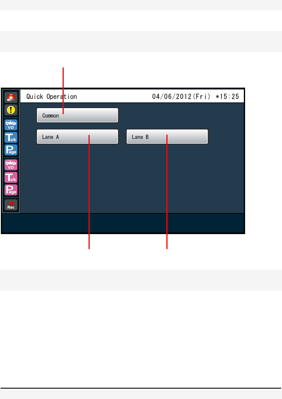
Quick Setup menu screen
(49)(48)
(47)
(47) Common button
Indicate the Quick Control screen of common Lane
(48) Lane A selection button
Display on the Lane A Quick Control screen
(49) Lane B selection button
Display on the Lane B Quick Control screen
How to operation on screen
The operation by direct touch with a finger
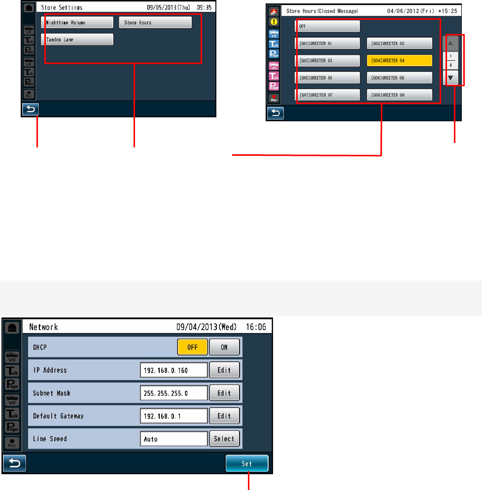
How to basic operation on screen
(2) Item selection button (3) Page change button
(1) Return button
(1) Return button
Return to upper level operation screen
(2) Item selection button
(3) Page change button
Finalizing the setting
(1) Set button
All items on the screen can be set with pressing the button at one time in case of multi items.
(1) Set button
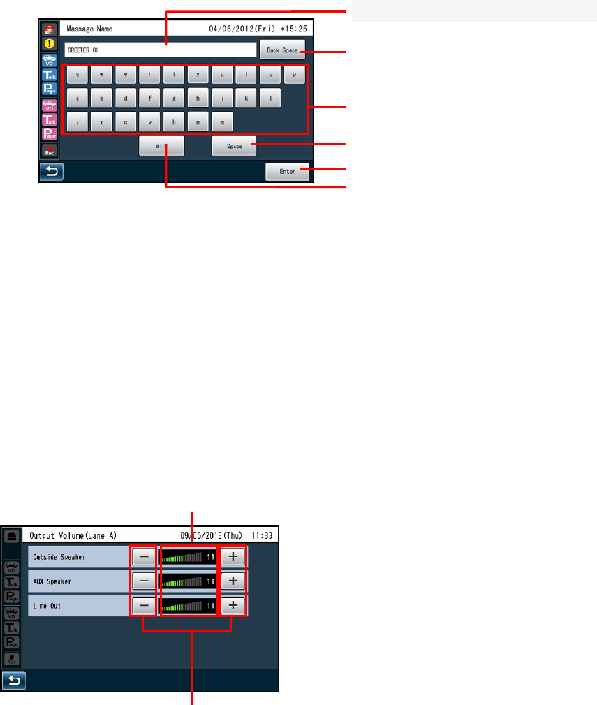
Input characters
- In case of input characters for passwords or address, use with keyboard.
(4) Base button
(5)Enter button
(6) Characters change button
(2) Backspace button
(3) Characters input buttons
(1) In
p
ut character dis
p
la
y
area
(1) Input character display area
Characters input display on the area
(2) Backspace button
(3) Characters input buttons
(4) Space button
(5) Enter/Login button
(6) Characters change button
Volume adjustment
(2) +,- buttons
(1) Volume level indication area
Indication volume level
(2) +, - buttons
4. How to operation
Basic Operation
- Communications with customers (TALK)
Store personnel wearing the headset can communicate bidirectionally with any customer who is at the menu
board.
- In regard to the method of talking, refer to the operating instructions of the Belt Pack (WX-CT420) or the
Communications with other Store Personnel (PAGE)
Store personnel wearing the headset can communicate with each other without being heard by customers.
In regard to the method of paging, refer to the operating instructions of the Belt Pack (WX-CT420) or the
All-in-One Headset (WX-CH450).
- Double Drive - Thru Lane Changeover (WX-CC412 only)
In the case of double drive-thru, it is possible to talk or page by selecting either Lane A or Lane B.
In regard to the method of lane changeover operation, refer to the operating instructions of the Belt Pack
(WX-CT420) or the All-in-One Headset (WX-CH450).
-Convenient Functions
Auto Talk Lock
When a customer approaches the menu board, it is automatically possible to make the predetermined
personnel’s headset (Belt Pack or All-in-One Headset) stay in TALK state. (The Talk Lock Mode is assumed.)
In regard to the method of Auto Talk Lock Mode setup, refer to the operating instructions of the Belt Pack
(WX-CT420) or the All-in-One Headset (WX-CH450).
Manager Mode
You can set one headset (Belt Pack or All-in-One Headset) to the manager mode in a Lane. Refer to the
operation manual of Belt Pack or All-in-One Headset about the setting method.
The headset set to the MANAGER MODE has following functionality.
- The manager can interrupt store personnel's TALK or PAGE at any time by monopolizing one channel by
priority.
- Speed Team
This SPEED TEAM operation is used at the congestion time.
Doesn't use the outside microphone and speaker. An Belt Pack or All-in-One Headset communicates order
from outside into the stores
Press the SPEED TEAM button of the Center Module.
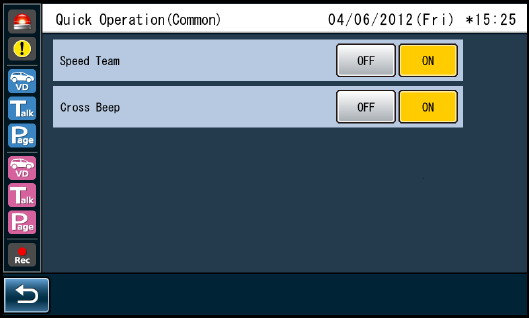
Quick setting screen (common)
1 The Belt Pack or All-in-One Headset allows the operator to hear the voice prompt of the "SPEED TEAM
ON".
2 The Belt Pack or All-in-One Headset allows the operator to communicate by pressing the PAGE button.
3 Press the PAGE button, and communication can be performed in the PAGE-LOCK mode. (Even if the
PAGE button is set to PTP, it operates by PAGE-LOCK.)
4 Press the SPEED TEAM button of the Center Module again, the SPEED TEAM mode will be released.
The Belt Pack or All-in-One Headset allows the operator to hear the voice prompt of the "SPEED TEAM
OFF".
Notes:
TALK is prohibited in the speed team mode.
If TALK is attempted with the Belt Pack or the All-in-One Headset, a voice prompt of "Operation not
allowed" is heard from the headset speaker.
When the customer approaches the menu board, the voice message recorded in the Center Module is
automatically output to the outside speaker. The Center Module has two memories, and you can select either
message.
- Vehicle Detector BEEP DAY/NIGHT
In the case of Double Drive-Thru configuration, it is possible to select the Vehicle Detector Beep tone to be
heard when a customer approaches the menu board.
Day/Night setup can be made by button operation at the front panel of this unit.
When the Day mode is set, the Beep Day/Night indicator of the center module will light in yellow. When the
Beep Day/Night button is pressed, the Night mode is assumed and this indicator will disappear.
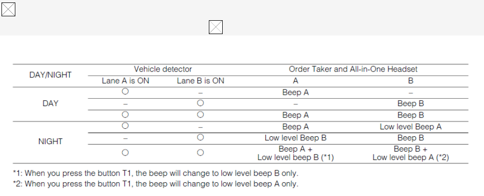
DAY mode:
When you are taking charge of lane A, if the vehicle detector is on the lane A, you will hear the
beep A. If the vehicle detector is on of the lane B, you will not hear the beep B.
NIGHT mode:
When you are taking charge of lane A, if the vehicle detector is on the lane A, you will hear the
beep A. If the vehicle detector is on of the lane B, you will hear the low level beep B. When both
vehicle detectors are on, you will alternately hear the beep A and the low level beep B.
Cross Beep:
Sound level of Cross Beep death-6dB Beep sound level, and value is reflected in conjunction
with the Beep volume level change.
When the Day mode is set, the Outside SP Level indicator of the center module will light in yellow. When
the Outside SP Level button is pressed, the Night mode is assumed and this indicator will disappear.
NIGHT mode: 50% level (Attenuation)
Note:
- If POS Remote is set for ON, you have to note that no button operation of the Outside Speaker
Level is possible at the center module.
- Vehicle Detector Normal/Override On
The Vehicle Detector operation can be set up.
Normal/Override On setup can be made by button operation at the front panel of this unit. When the
Override On mode is set, the V/D Override indicator of the center module will light in yellow. When the
V/D Override button is pressed, the Normal mode is assumed and this indicator will disappear.
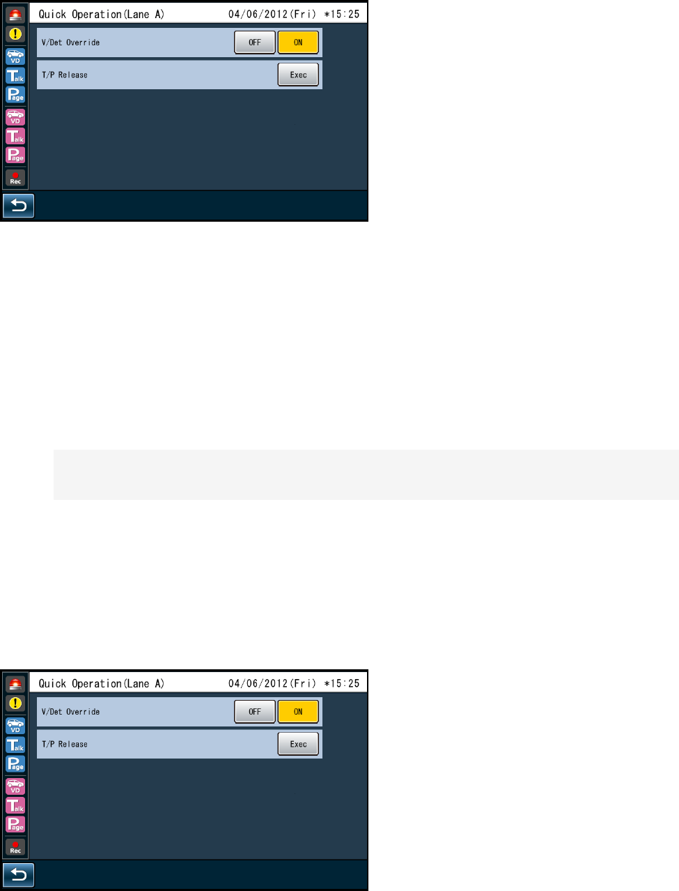
Quick setting screen (each lane)
NORMAL:
The vehicle detector turns on only when a vehicle is detected at the menu board. When the
detector turns on, a beep tone is heard in the headset. When the Talk button is pressed on the
Belt Pack or All-in-One Headset side, the Outside Speaker and the Outside Microphone are
turned ON at the menu board.
When the vehicle leaves, the vehicle detector turns off. When setting the normal position, Auto
Talk Lock mode is enabled.
OVERRIDE ON:
When set to ON VD Override, microphones menu board is a state that can turned ON at all times,
even when the TALK VD of fact is not ON.
Talk/Page Release
In Talk or Page mode, any talk is temporarily interrupted at the headset (Belt Pack or All-in-One Headset).
Operation of Talk/Page Release is possible by button operation at the front panel of this unit.
Quick setting screen (each lane)
Notes:
It is impossible to release the Talk or Page mode of the All-in-One Headset or Belt Pack in the
manager mode
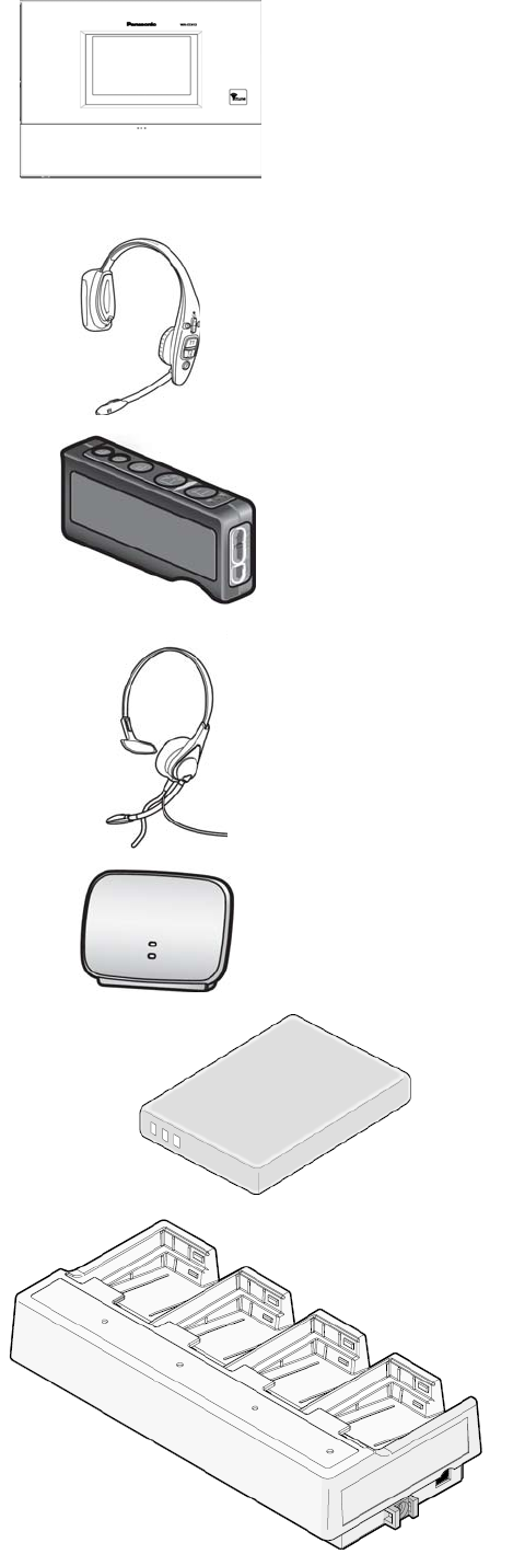
System Parts and Accessories
Center Module
WX-CC411
WX-CC412
All-In-One Headset
WX-CH450
Belt Pack
WX-CT420
Headset
WX-CH427
Wireless Repeater
WX-CR470
Battery
WX-B3030 (1UF653450R-MDSP)
Battery Charger
WX-Z3040A
■ Installation procedures
Preparations (Refer to page xx.)
Installation of center modules on the wall (Refer to page xx.)
Wiring to the center modules
(Refer to page xx.)
ID registration for follower units
(Refer to page xx.)
[System Setup]
Installed System Setting (Refer to page xx.)
Adjustments to adequate sound levels
Preparations
This Center Module is designed to be mounted on a wall via wall bracket. Please be advised of the
following:
- Procure 4 mounting screws according to the material of the installation area.
In this case, wood screws and nails should not be used.
Recommended screw: M4 x 25 mm
- Required pull-out capacity of a single screw/bolt is 118 N {12 kgf} or more.
- If a wall board is too weak to support the total weight, the area shall be sufficiently reinforced.
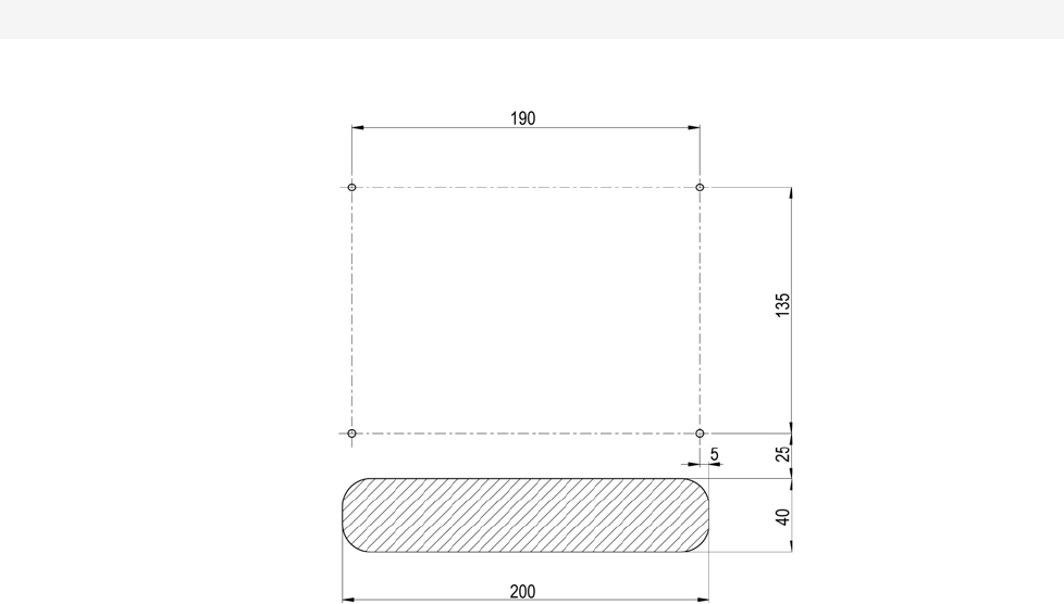
How to instillation
Determination of the mounting position
Open the hole for connection wires, and determine the screw mounting position of the four locations as the
figure below. (Unit: mm)
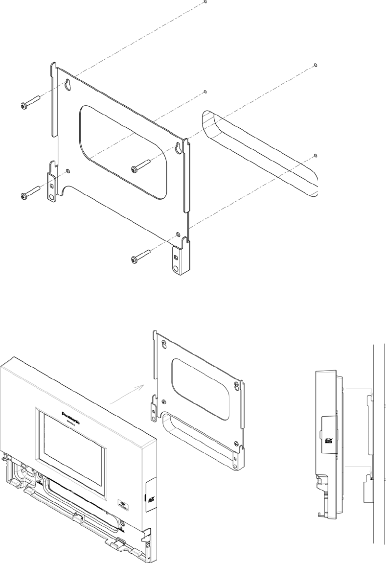
Fixing
1. Wall bracket and 4 screws (4.1 mm X25 mm) used for fixing.
(Required pull-out capacity of a single screw/bolt is 118 N {12 kgf} or more.)
2. Attach the hook part of the body wall bracket (4 places).
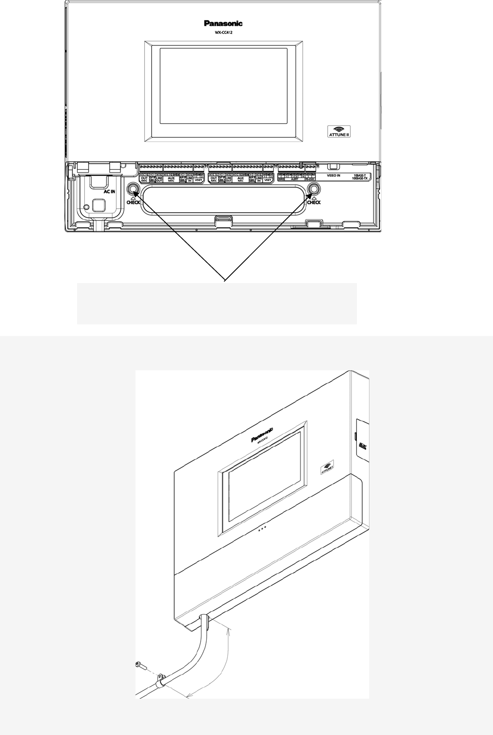
3. Make sure that the body is stuck completely through confirmation window [CHECK]
If you can visually stamp completely, it is properly installed.
Stamp is not visible, or if you are missing, it is not installed
correctly. If possible visibility, it is installed correctly.
4. Using the wall fixing clamp the supplied power cord and mounting (25 mm 4.1 mm ×) screws provided.
[Minimum pull-out strength 780 N {80 kgf}]
150 ㎜~200 ㎜
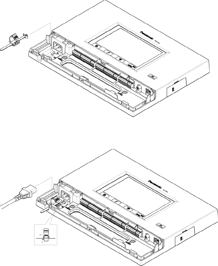
Clamping the Power Plug and Power Cord
Important:
Surely clamp the power plug to this center module and screw the AC cable to the wall using the
provided AC cable clamper.
1 Insert an AC cable holder into the hole under the AC inlet.
Slide the holder to the backward by pushing down the clamp lever.
2 Insert the power plug into the power cord inlet.
3 Push the holder forward until the holder touches the power plug.
4 Lock the holder
5 Clamp the AC cable with the provided clamp, and secure the AC cable clamper to the wall by
fastening the screws.
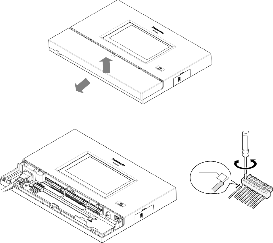
■ Wiring to the center modules
1 Remove the terminal cover.
Slide the front cover downwards by pressing its arrow-marked part and pull the lower side of the
cover toward you.
2 Insert a “minus” screwdriver in the slot as illustrated and remove the terminal socket from the main
unit.
7 ㎜ 1 ㎜
{9/32
inches
1
/16
3 Connect the wiring material to the terminal socket.
Use the “minus” screwdriver and loosen the screw located on the upper surface of the terminal
socket.
Peel off the sheath from the tip of the wiring material and insert the cable tip in the terminal socket.
Firmly tighten the loosened screw by means of the “minus” screwdriver.
Repeat the above-mentioned same procedure for each terminal.
Notes:
Process the wires according to the following:
Recommended wire type: AWG 28 - 16 (Do not use soldered wires.)
Length to be stripped: 7 mm ± 1 mm {9/32" ± 1/16"} Diameter of screw: ø 2 mm {3/32"}
Check to be sure that the wires are securely connected.
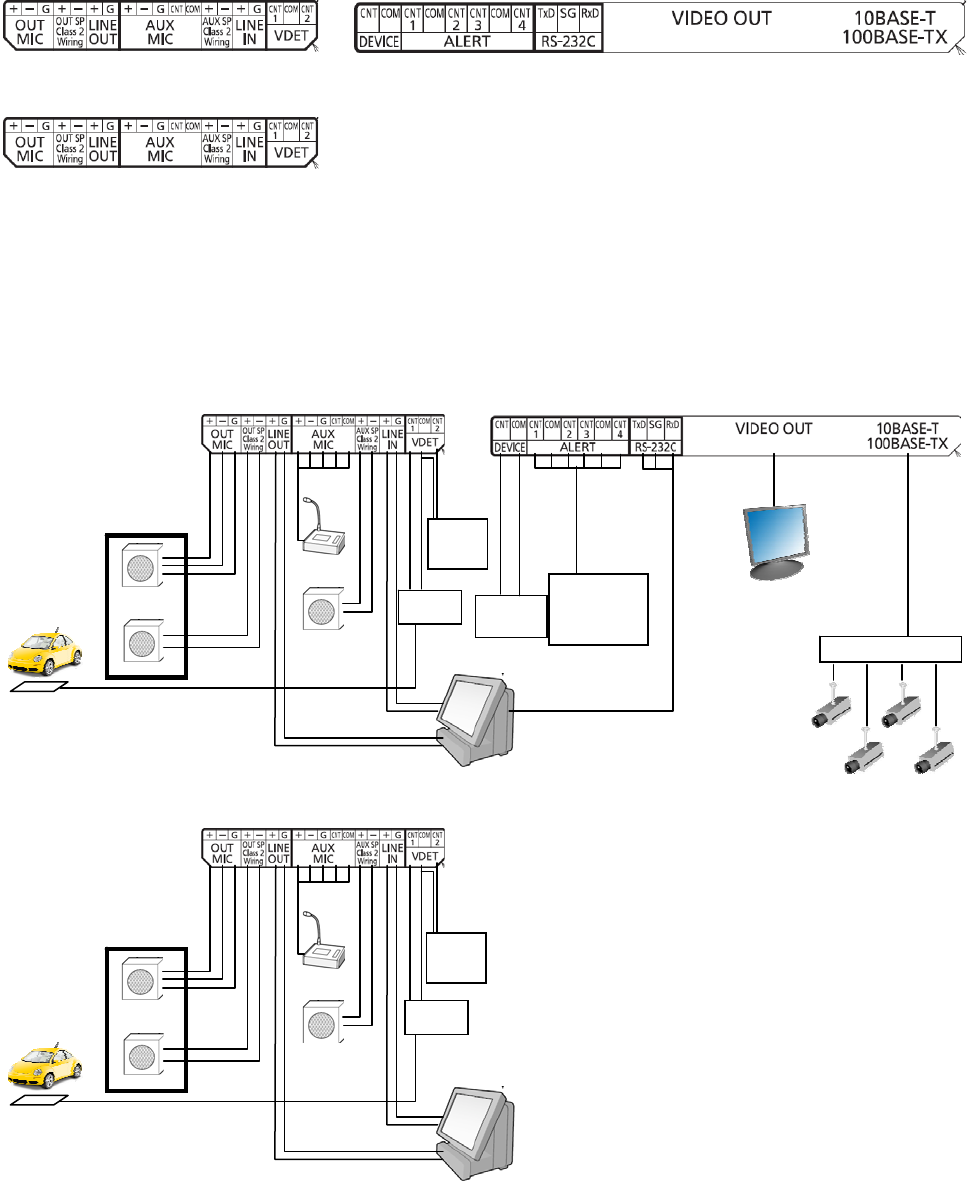
● Refer to the following lists attached on the inside of the terminal cover to make connections.
<For Lane A>
<For Lane B>
■ Basic Connection
This diagram shows the basic system connection.
Order Post
Microphone
Speaker (8)
Drive thru lane
Kitchen
Mic
Kitchen SP (8)
External
Device
Ve h ic le
Detector
Sensor
+Refrigerator
+Cashier
+etc...
Extension
Ve h ic le
Detector
PC
Kitchen
HUB
Monitor
Drive thru lane
Kitchen
Mic
Extension
Ve h ic le
Detector
Veh i c le
Detector
Kitchen SP (8)
Order Post
Microphone
Speaker (8)
PC
Specifications
Operating frequency (TX/RX): 1 920 MHz-1 930 MHz
Power supply: 120 V AC, 60 Hz
Power consumption: 11 W
Outside speaker: 1.25 W, 8
AUX speaker: 1.25 W, 8
Dimensions: 404 mm (W) x 265 mm (H) x 69 mm (D)
{15-15/16" (W) x 10-7/16" (H) x 2-3/4" (D)}
Weight: 2.3 kg {5.07 lbs.}
Ambient operating temperature: –10 °C to +50 °C {14 °F to 122 °F}
Dimensions and weighs indicated are approximate.
Specifications are subject to change without notice.
■ Standard accessories
Operating Instructions (this manual) ................................ 1 pc.
AC cable .......................................................................... 1 pc.
AC cable holder ............................................................... 1 pc.
Miniture screw driver ........................................................ 1 pc.
AC cable clamper ............................................................ 1 pc.
Wall Bracket. ........ ........................................................... 1 pc.