Panasonic of North America 9TAWX-CT2030 Transceiver for Wireless Communication System User Manual 3TR001757AAA SAMPLE
Panasonic Corporation of North America Transceiver for Wireless Communication System 3TR001757AAA SAMPLE
UserManual.wiki
>
Panasonic of North America
>
9TAWX CT2030 User Manual
User Manual
Navigation menu
Upload a User Manual
Namespaces
Wiki Guide
HTML
PDF
Info
Views
User Manual
Discussion / Help
Navigation
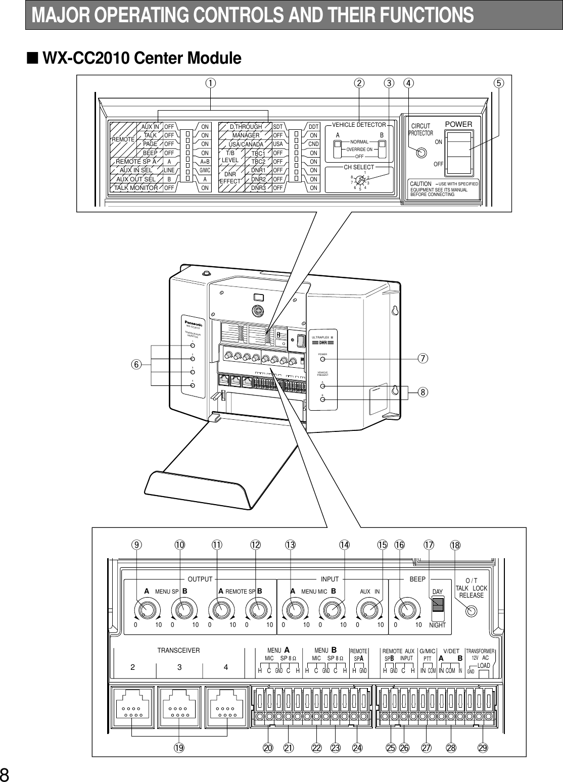
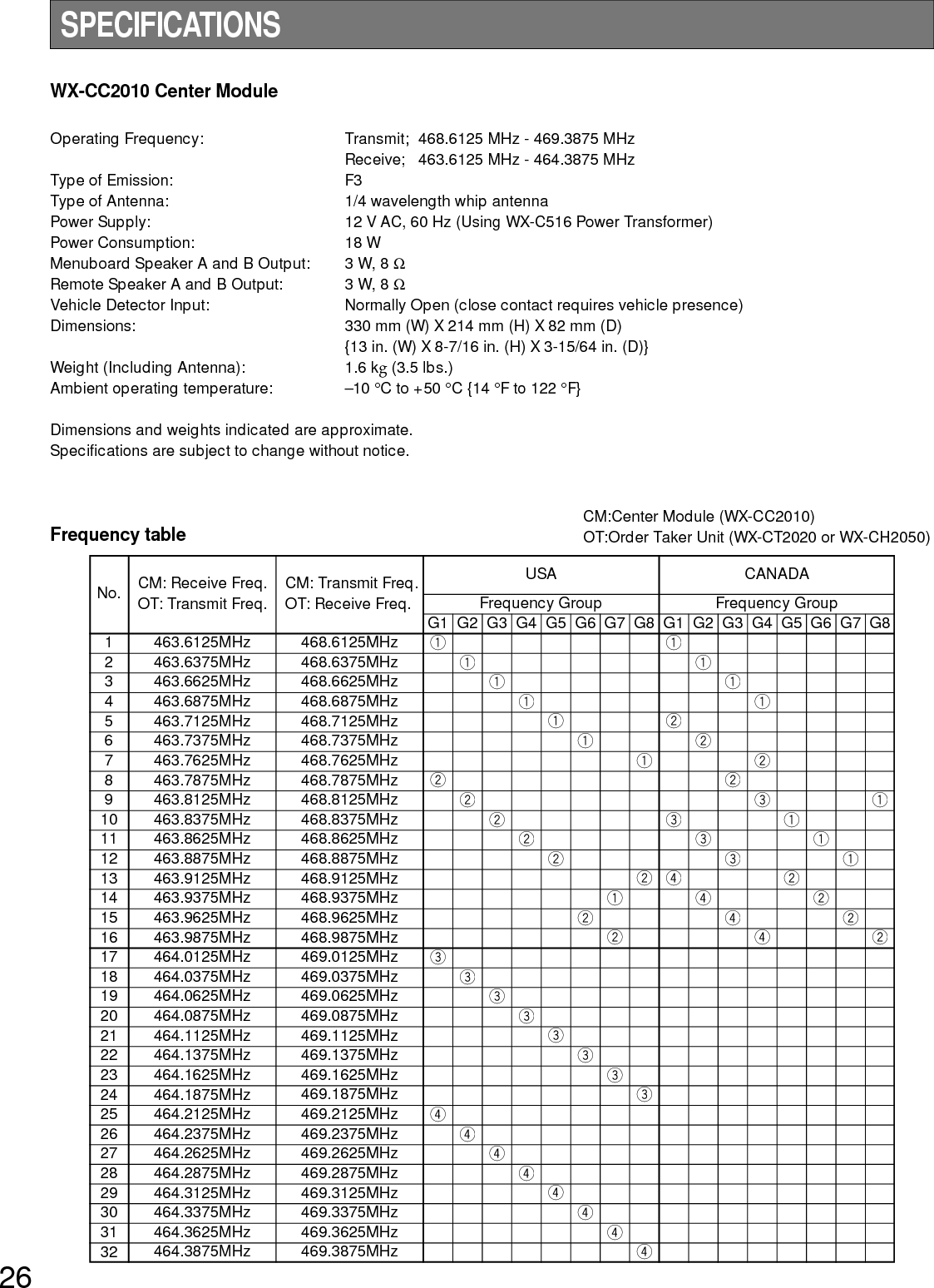
![9Notes:•The following switches and terminals should be usedby qualified service personnel or system installersonly.•To change the setting of the following switches, turnoff the power of the center module, then turn it backon.qAuxiliary Input On/Off Switch (REMOTE AUX IN,ON/OFF)Set this switch to ON to output the audio (that hasbeen input from the AUX INPUT terminals) to theREMOTE SP terminals.Talk On/Off Switch (REMOTE TALK, ON/OFF)To monitor the conversation between the store person-nel and customer with the remote speaker, set thisswitch to ON.Page On/Off Switch (REMOTE PAGE, ON/OFF)To monitor the conversation among the store person-nel with the remote speaker, set this switch to ON.Beep On/Off Switch (REMOTE BEEP, ON/OFF)Set this switch to ON to output beep sounds to theremote speakers.Remote Speaker A Switch (REMOTE SP A)The menuboard microphone(s) to output the sound(s)from Remote Speaker A is [are] selected with thisswitch.A: Remote Speaker A outputs the sound ofMenuboard Microphone A.A + B: Remote Speaker A outputs the mixed sound ofMenuboard Microphone A and B.Auxiliary Input Selection Switch(AUX IN SEL, G MIC*/LINE)* "G MIC" is marked as "G/MIC" on the switch panel.This switch selects the auxiliary input level.G MIC (Gooseneck Microphone)This can be used as a wired system.Input : -62 dBV, balancedLINEInput : -20 dBV, balancedAUX Output Selection Switch (AUX OUT SEL)The menuboard speaker to send the auxiliary input isselected with this switch.A: The auxiliary input is sent to the MenuboardSpeaker A.B: The auxiliary input is sent to the MenuboardSpeaker B.Talk Monitor On/Off Switch (TALK MONITOR,ON/OFF)This switch should be normally set to OFF.Consult your servicing dealer before attempting tochange this switch.D-THROUGH Selection Switch (D. THROUGH,DDT/SDT)SDT (Single Drive Through) or DDT (Double DriveThrough) is selected with this switch. (Refer to p. 15OPERATION MODE DESCRIPTIONS for details.)Manager Switch (MANAGER)The Manager mode is set to ON or OFF with thisswitch. (Refer to p. 15 OPERATION MODE DESCRIP-TIONS for details.)USA/Canada Switch (USA/CANADA)To select a radio frequency suitable for the region, setthis switch as follows.USA: This setting is available in the United States.CND: This setting is available in Canada.Talkback Level Control Switch (T/B LEVEL: TBC1,TBC2, ON/OFF)These switches are used for the talkback level settingof the order taker unit.Change the settings if the talkback level is too high.Note: These settings are activated when the DNRswitch is set to ON.DNR (Digital Noise Reduction) Effect Level ControlSwitch(DNR EFFECT: DNR1, DNR2, DNR3, ON/OFF)These switches are used for the noise reduction levelsetting.The more the noise is reduced, the lower the soundquality will be. The following table shows the relation-ship between noise reduction level and sound quality.Note: No setting should be done other than shown inthe table.Setting TalkbackLevelTBC1TBC2TBC1TBC2TBC1TBC2TBC1TBC2Normally set to this position.Talkback level set to 50 %.Talkback level set to 35 %.Talkback level set to 25 %.Remarks–6 dB–9 dB–12 dB– Talkback is off.](https://usermanual.wiki/Panasonic-of-North-America/9TAWX-CT2030/User-Guide-364932-Page-9.png)
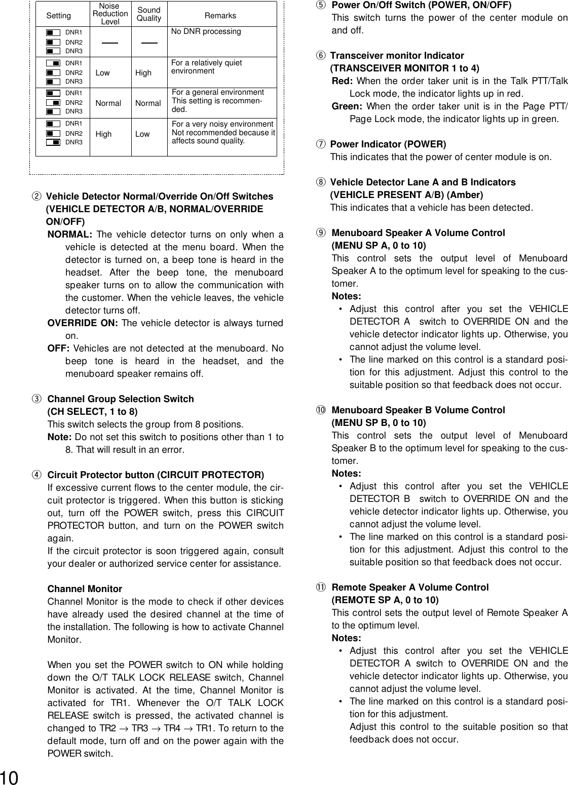
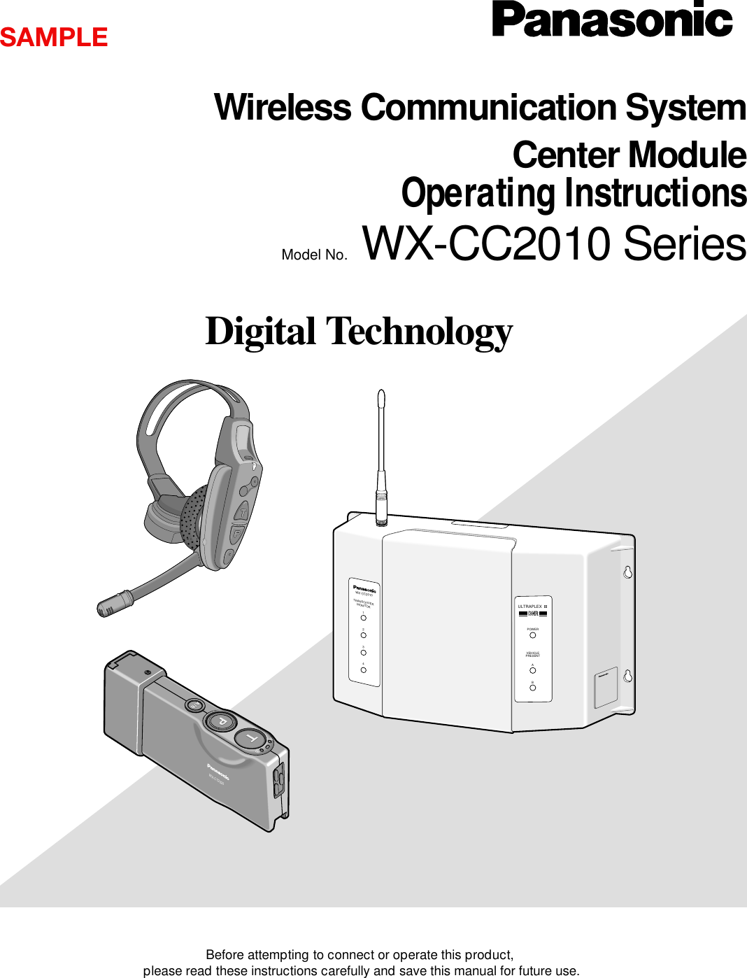
![16WX-CC2010WX-CC2010TRANSCEIVERMONITOR1234ULTRAPLEX IIPOWERVEHICLEPRESENTDNRDNRAB:Communication area WX-CT2020 / WX-CH2050 can receive the transmission signals from WX-CC2010.:Non-communication area WX-CT2020 / WX-CH2050 cannot receive the transmission signals from WX-CC2010. Center Module Dip Switch Setting [D·THROUGH]: SDT [MANAGER]: OFF WX-CT2020 / WX-CH2050 Dip Switch Setting [D·THROUGH]: SDT [MANAGER]: OFF [Role Assignment]: Assistant [Area Expansion]: NormalOPERATION MODE DESCRIPTIONSThe following descriptions are operation modes available using WX-CC2010 Center Module and WX-CT2030 Transceiver.Notes:•"User" mentions a person using WX-CT2020 Order Taker Unit or WX-CH2050 All-in-One Headset.•When more than one user exists in the same area, the nearest user will receive the transmission signal from WX-CC2010 /WX-CT2030.■Operation Mode 1 (Same as WX-C1011 and WX-C1020 System)This is the basic operation mode that is also employed by current models other than WX-CC2010. •In the TALK mode, a user can communicate with a customer at the menu board. •In the PAGE mode, two users can communicate with each other.](https://usermanual.wiki/Panasonic-of-North-America/9TAWX-CT2030/User-Guide-364932-Page-16.png)
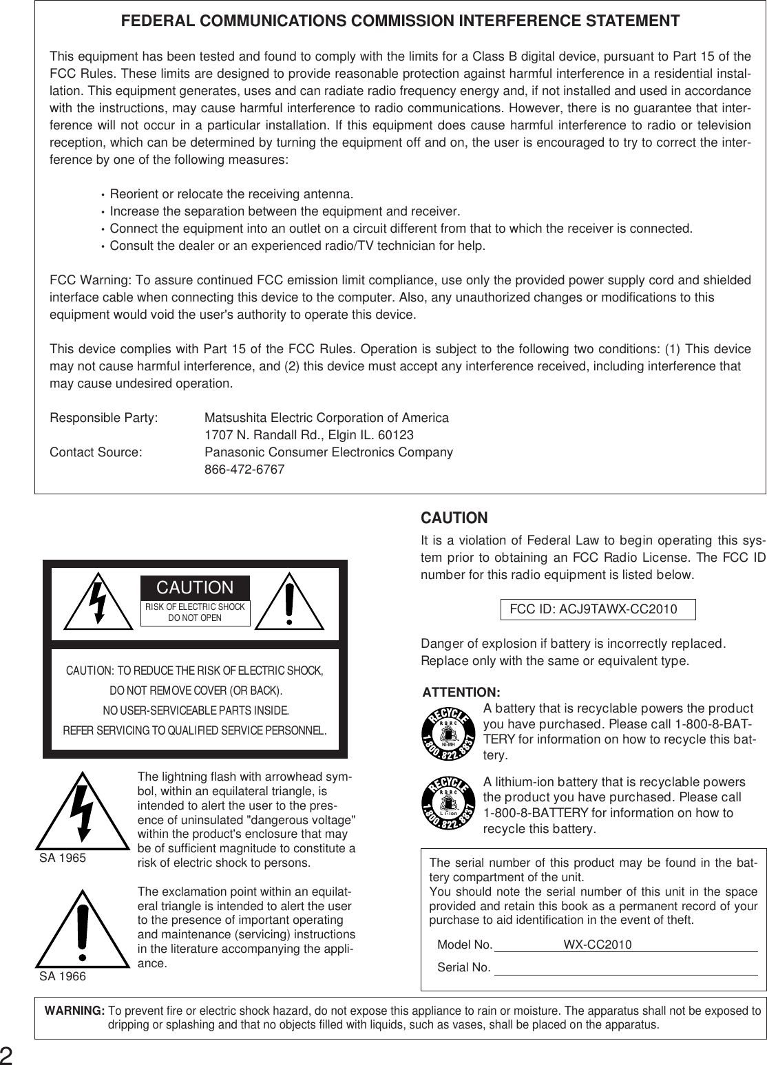
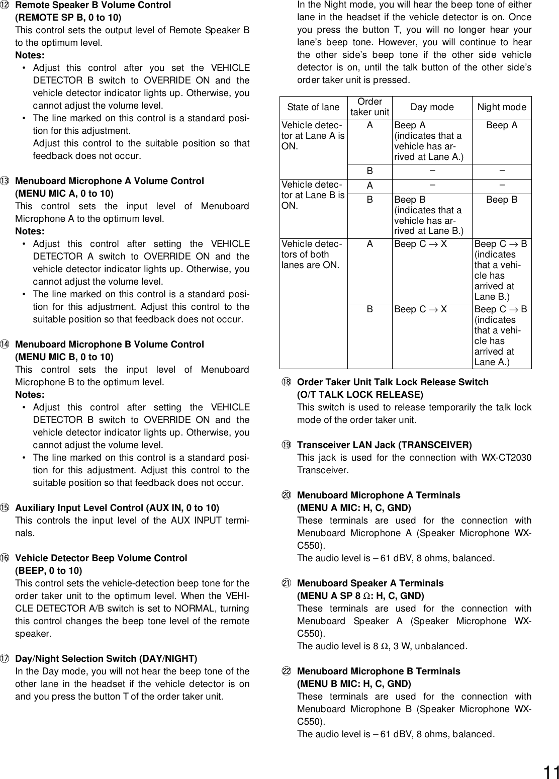
![17* w to rshows the transceiver No.It is the same as TRANSCEIVER jack No.of WX-CC2010.30.48 m{100 ft.}or moreWX-CC2010TRANSCEIVERMONITOR1234ULTRAPLEX IIPOWERVEHICLEPRESENTDNRDNRAB WX-CT2020 / WX-CH2050 Dip Switch Setting [D·THROUGH]: SDT [MANAGER]: OFF [Role Assignment]: Assistant [Area Expansion]: Expand:Communication area WX-CT2020 / WX-CH2050 can receive the transmission signals from WX-CT2030.:Communication area of WX-CC2010 WX-CT2020 / WX-CH2050 can receive the transmission signals from WX-CC2010.:Non-communication area Center Module Dip Switch Setting [D·THROUGH]: SDT [MANAGER]: OFF WX-CC2010WX-CT2030w*WX-CC2010 x 1, WX-CT2030 x 1■Operation Mode 2 (Area Expansion)By using WX-CT2030 Transceiver, you can expand the communication area of Operation Mode 1. •Up to three WX-CT2030 can be added.•The number of users who can simultaneously communicate in the TALK / PAGE mode depends on the total number oftransceivers (WX-CC2010 x 1 + WX-CT2030 x ∗).Note: "∗" is the number of WX-CT2030.WX-CC2010TRANSCEIVERMONITOR1234ULTRAPLEX IIPOWERVEHICLEPRESENTDNRDNRAB30.48 m{100 ft.}or moreWX-CC2010WX-CT2030wWX-CT2030e30.48 m {100 ft.}or moreWX-CC2010 x 1, WX-CT2030 x 2WX-CC2010TRANSCEIVERMONITOR1234ULTRAPLEX IIPOWERVEHICLEPRESENTDNRDNRABWX-CC2010 WX-CT2030eWX-CT2030wWX-CT2030r30.48 m{100 ft.}or more30.48 m{100 ft.}or more30.48 m{100 ft.}or more30.48 m{100 ft.}or moreWX-CC2010 x 1, WX-CT2030 x 3](https://usermanual.wiki/Panasonic-of-North-America/9TAWX-CT2030/User-Guide-364932-Page-17.png)
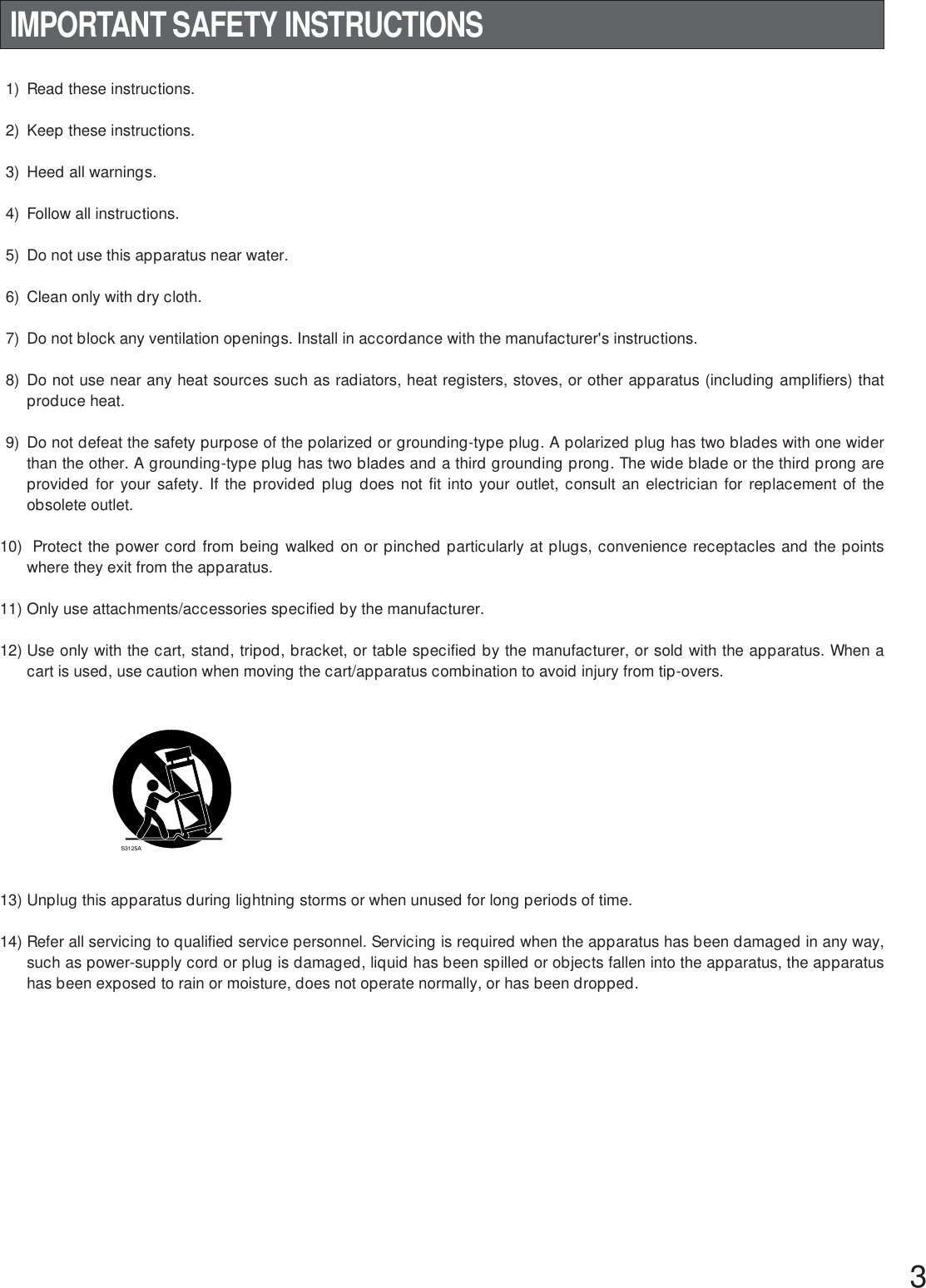
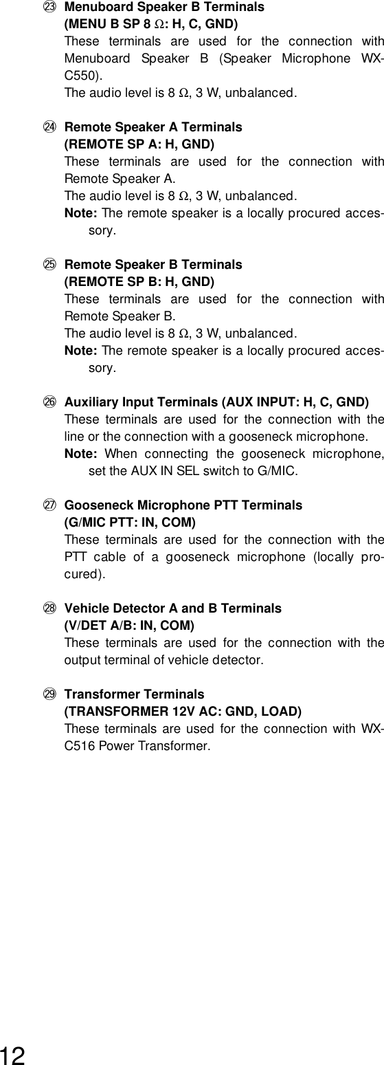
![18■Operation Mode 3 (Manager Mode)In this operation mode, you can assign the role of manager / assistant personnel to each user.•The manager has the communication priority to assistant personnel. The manager can cut into a conversation with a cus-tomer even when one of assistant personnel is communicating with the customer in the TALK mode. •In the PAGE mode, the manager can communicate with one of the assistant personnel. Note: Set WX-CT2030 Transceiver in the area that covers the moving range of the manager.WX-CC2010TRANSCEIVERMONITOR1234ULTRAPLEX IIPOWERVEHICLEPRESENTDNRDNRABWX-CC2010WX-CT2030w*:Communication area for Manager WX-CT2020 / WX-CH2050 can receive the transmission signals from WX-CT2030.:Communication area for Manager / Assistant Personnal • WX-CT2020 / WX-CH2050 for the manager can receive the transmission signals from WX-CT2030. • WX-CT2020 / WX-CH2050 for the assistant personnel can receive the transmission signals from WX-CC2010. • The manager has the communication priority.:Non-communication Area Center Module Dip Switch Setting [D·THROUGH]: SDT [MANAGER]: ON WX-CT2020 / WX-CH2050 Dip Switch Setting [Manager] [D·THROUGH]: SDT [MANAGER]: ON [Role Assignment]: Manager [Area Expansion]: Normal WX-CT2020 / WX-CH2050 Dip Switch Setting [Assistant] [D·THROUGH]: SDT [MANAGER]: ON [Role Assignment]: Assistant [Area Expansion]: Normal* w shows the transceiver No.It is the same as TRANSCEIVER jack No.of WX-CC2010.3.05 m {10 ft.} or more](https://usermanual.wiki/Panasonic-of-North-America/9TAWX-CT2030/User-Guide-364932-Page-18.png)
![19■Operation Mode 4 (Area Expansion with Manager)By adding two WX-CT2030 Transceivers (x 1 to the assistant area and x 1 to the manager area), you can expand the commu-nication areas of Operation Mode 3. •The number of users who can simultaneously communicate in the TALK / PAGE mode depends on the total number oftransceivers (WX-CC2010 x 1 + WX-CT2030 x ∗).Note: "∗" is the number of WX-CT2030.•The manager has the communication priority to assistant personnel. The manager can cut into a conversation with a cus-tomer even when one of assistant personnel is communicating with the customer in the TALK mode. Note: Set WX-CT2030 Transceiver (Manager) in the area that covers the moving range of the manager.WX-CC2010WX-CT2030w*(Manager)WX-CT2030e(Assistant)WX-CT2030r(Manager)3.05 m {10 ft.} or moreWX-CC2010TRANSCEIVERMONITOR1234ULTRAPLEX IIPOWERVEHICLEPRESENTDNRDNRAB3.05 m {10 ft.} or moreKeep the distance of 30.48 m {100 ft.} or more between (1) and (2).(1): WX-CC2010 / WX-CT2030 w(2): WX-CT2030 e / r:Communication area for Manager WX-CT2020 / WX-CH2050 of the manager can receive the transmission signals from WX-CT2030.:Communication area for Manager / Assistant Personnal • WX-CT2020 / WX-CH2050 for the manager can receive the transmission signals from WX-CT2030 (Manager). • WX-CT2020 / WX-CH2050 for the assistant personnel can receive the transmission signals from WX-CC2010/ WX-CT2030 (Assistant). • The manager has the communication priority.:Non-communication area* w shows the transceiver No.It is the same as TRANSCEIVER jack No. of WX-CC2010. Center Module Dip Switch Setting [D·THROUGH]: SDT [MANAGER]: ON WX-CT2020 / WX-CH2050 Dip Switch Setting [Manager] [D·THROUGH]: SDT [MANAGER]: ON [Role Assignment]: Manager [Area Expansion]: Expand WX-CT2020 / WX-CH2050 Dip Switch Setting [Assistant] [D·THROUGH]: SDT [MANAGER]: ON [Role Assignment]: Assistant [Area Expansion]: Expand](https://usermanual.wiki/Panasonic-of-North-America/9TAWX-CT2030/User-Guide-364932-Page-19.png)
![20■Operation Mode 5 (Double Drive Through)This operation mode can be applied for a Double Drive Through composition.•The number of users who can simultaneously communicate in the TALK / PAGE mode depends on the total number oftransceivers (WX-CC2010 x 1 + WX-CT2030 x ∗).Note: "∗" is the number of WX-CT2030.•Communication Area Lane A covers Menuboard A, and Communication Area Lane B covers Menuboard B.•The users can switch the communication between a customer at Menuboard A/B with the A/B channel selection button.(Refer to the operating instructions of WX-CT2020 Order Taker Unit or WX-CH2050 All-in-One Headset.)Note: Communication is not established soon after Communication Area Lane A/B is switched.Speak to the customer a few seconds after pressing the A/B channel selection button.WX-CC2010TRANSCEIVERMONITOR1234ULTRAPLEX IIPOWERVEHICLEPRESENTDNRDNRABWX-CC2010WX-CT2030w*3.05 m {10 ft.} or moreCenter Module Dip Switch Setting[D·THROUGH]: DDT[MANAGER]: OFFWX-CT2020 / WX-CH2050 Dip Switch Setting[D·THROUGH]: DDT[MANAGER]: OFF[Role Assignment]: Assistant[Area Expansion]: Normal: Communication Area Lane AWX-CT2020 / WX-CH2050 in this area can receive the transmission signals from WX-CC2010.: Communication Area Lane BWX-CT2020 / WX-CH2050 in this area can receive the transmission signals from WX-CT2030.* w shows the transceiver No.It is the same as TRANSCEIVER jack No. of WX-CC2010.: Non-communication Area](https://usermanual.wiki/Panasonic-of-North-America/9TAWX-CT2030/User-Guide-364932-Page-20.png)
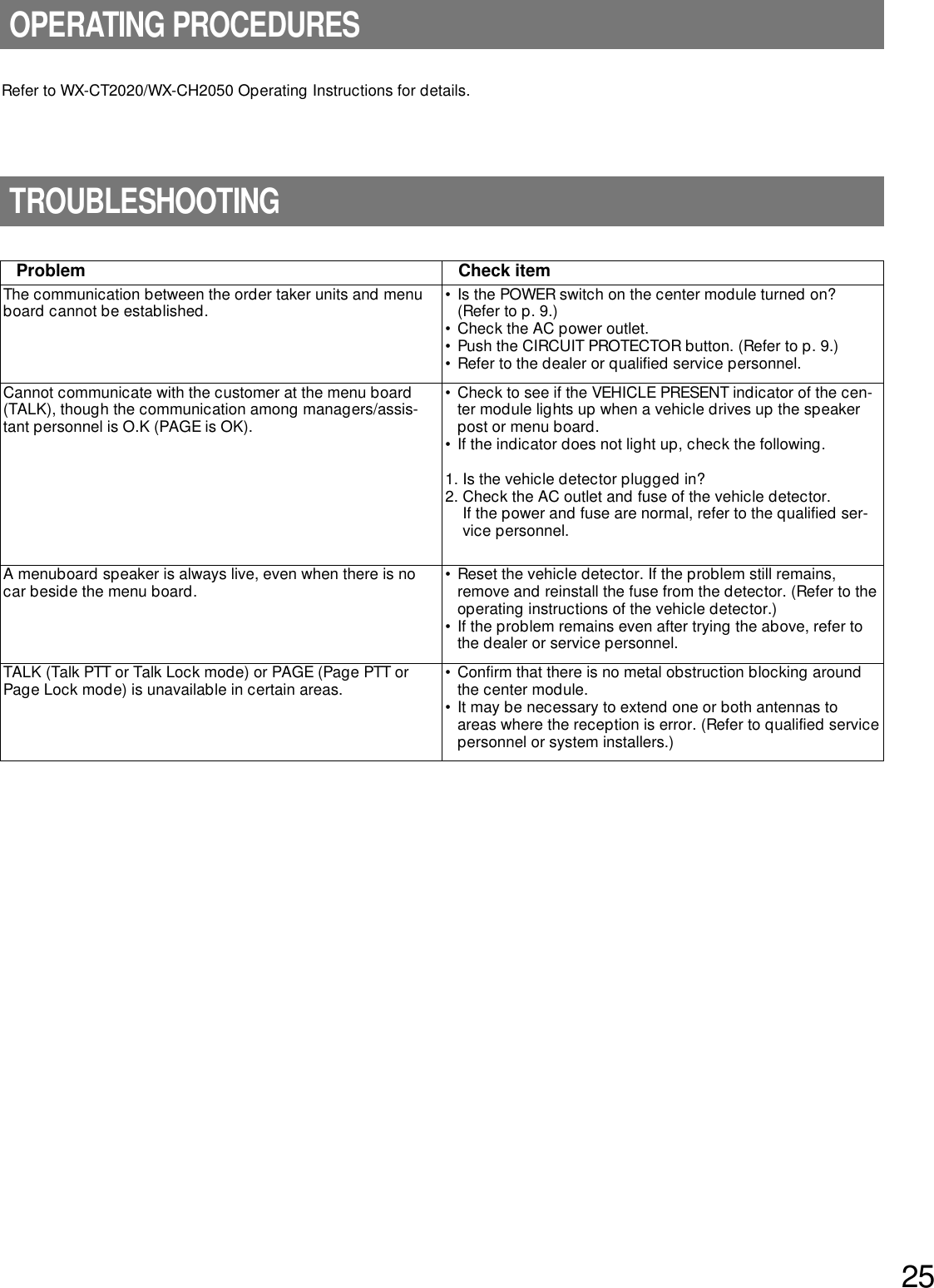
![21■Operation Mode 6 (Double Drive Through with Area Expansion)By adding two WX-CT2030 Transceivers (x 1 to the assistant area and x 1 to the manager area), you can expand the commu-nication areas of Operation Mode 5.•The number of users who can simultaneously communicate in the TALK / PAGE mode depends on the total number oftransceivers (WX-CC2010 x 1 + WX-CT2030 x ∗).Note: "∗" is the number of WX-CT2030.•Communication Area A covers Menuboard A, and Communication Area B covers Menuboard B.•The users can switch the communication between a customer at Menuboard A/B with the A/B channel selection button.(Refer to the operating instructions of WX-CT2020 Order Taker Unit or WX-CH2050 All-in-One Headset.)Note: Communication is not established soon after Communication Area Lane A/B is switched.Speak to the customer a few seconds after pressing the A/B channel selection button.WX-CC2010TRANSCEIVERMONITOR1234ULTRAPLEX IIPOWERVEHICLEPRESENTDNRAB3.05 m {10 ft.}or more3.05 m {10 ft.}or moreWX-CC2010(Lane A)WX-CT2030w*(Lane B)WX-CT2030e(Lane A)WX-CT2030r(Lane B)Keep the distance of 30.48 m {100 ft.} or more between (1) and (2).(1): WX-CC2010 / WX-CT2030 w(2): WX-CT2030 e / r: Communication Area Lane AWX-CT2020 / WX-CH2050 in this area can receive the transmission signals from WX-CC2010 / WX-CT2030 (Lane A).: Communication Area Lane BWX-CT2020 / WX-CH2050 in this area can receive the transmission signals from WX-CT2030 (Lane B).* w shows the transceiver No.It is the same as TRANSCEIVER jack No. of WX-CC2010.: Non-communication AreaCenter Module Dip Switch Setting[D·THROUGH]: DDT[MANAGER]: OFFWX-CT2020 / WX-CH2050 Dip Switch Setting[D·THROUGH]: DDT[MANAGER]: OFF[Role Assignment]: Assistant[Area Expansion]: Expansion](https://usermanual.wiki/Panasonic-of-North-America/9TAWX-CT2030/User-Guide-364932-Page-21.png)
![22■Operation Mode 7 (Double Drive Through with Manager Mode)This operation mode can be applied when you assign the role of manager / assistant personnel to each user in a Double DriveThrough composition.•The number of users who can simultaneously communicate in the TALK / PAGE mode depends on the total number oftransceivers (WX-CC2010 x 1 + WX-CT2030 x ∗).Note: "∗" is the number of WX-CT2030.•Communication Area Lane A covers Menuboard A, and Communication Area Lane B covers Menuboard B.•The users can switch the communication between a customer at Menuboard A/B with the A/B channel selection button.(Refer to the operating instructions of WX-CT2020 Order Taker Unit or WX-CH2050 All-in-One Headset.)Note: Communication is not established soon after Communication Area Lane A/B is switched.Speak to the customer a few seconds after pressing the A/B channel selection button.•The manager has the communication priority to assistant personnel. The manager can cut into a conversation with a cus-tomer even when one of assistant personnel is communicating with the customer in the TALK mode. Note: Set WX-CT2030 (Lane A/B – Manager) in the area that covers the moving range of the manager.WX-CC2010TRANSCEIVERMONITOR1234ULTRAPLEX IIPOWERVEHICLEPRESENTDNRDNRABWX-CC2010(Lane A-Assistant)3.05 m {10 ft.}or moreWX-CT2030e(Lane A-Manager)WX-CT2030r(Lane B-Manager)WX-CT2030w*(Lane B-Assistant)3.05 m {10 ft.} or moreKeep the distance of 3.05 m {10 ft.} or more between (1) and (2).(1): WX-CC2010 / WX-CT2030 e(2): WX-CT2030 w / r: Communication Area Lane A - ManagerWX-CT2020 / WX-CH2050 in this area can receive the transmission signals from WX-CT2030 (Lane A - Manager).This area has the communication priority to the communication area Lane A - Assistant.: Communication Area Lane A - AssistantWX-CT2020 / WX-CH2050 in this area can receive the transmission signals from WX-CC2010 (Lane A - Assistant).: Communication Area Lane B - AssistantWX-CT2020 / WX-CH2050 in this area can receive the transmission signals from WX-CT2030 (Lane B - Assistant).: Communication Area Lane B - ManagerWX-CT2020 / WX-CH2050 in this area can receive the transmission signals from WX-CT2030 (Lane B - Manager).This area has the communication priority to the communication area Lane B - Assistant. WX-CT2020 / WX-CH2050 Dip Switch Setting • Lane A / B - Manager [D·THROUGH]: DDT [MANAGER]: ON [Role Assignment]: Manager [Area Expansion]: Normal Center Module Dip Switch Setting [D·THROUGH]: DDT [MANAGER]: ON • Lane A / B - Assistant [D·THROUGH]: DDT [MANAGER]: ON [Role Assignment]: Assistant [Area Expansion]: Normal* w shows the transceiver No.It is the same as TRANSCEIVER jack No. of WX-CC2010.: Non-communication Area](https://usermanual.wiki/Panasonic-of-North-America/9TAWX-CT2030/User-Guide-364932-Page-22.png)