Panasonic of North America 9TAWX-CT2030 Transceiver for Wireless Communication System User Manual 3TR001757AAA SAMPLE
Panasonic Corporation of North America Transceiver for Wireless Communication System 3TR001757AAA SAMPLE
User Manual
Before attempting to connect or operate this product,
please read these instructions carefully and save this manual for future use.
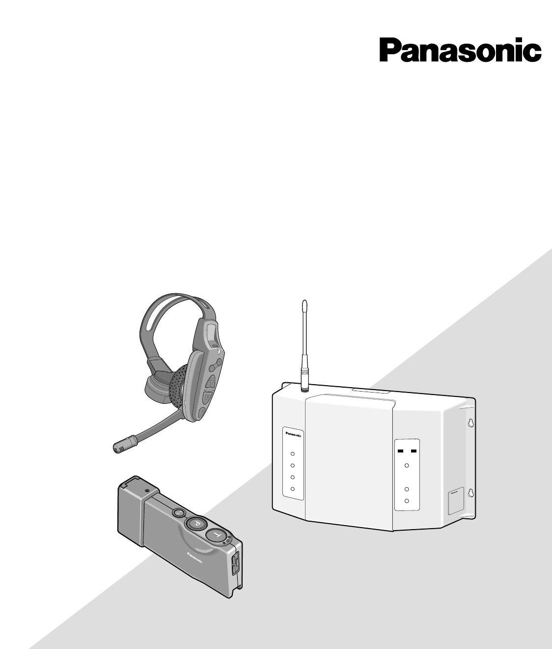
Model No. WX-CC2010 Series
Wireless Communication System
Center Module
Operating Instructions
Digital Technology
WX-CC2010
TRANSCEIVER
MONITOR
1
2
3
4
ULTRAPLEX II
POWER
VEHICLE
PRESENT
DNRDNR
A
B
AB
WX-CT2020
SAMPLE
2
FEDERAL COMMUNICATIONS COMMISSION INTERFERENCE STATEMENT
This equipment has been tested and found to comply with the limits for a Class B digital device, pursuant to Part 15 of the
FCC Rules. These limits are designed to provide reasonable protection against harmful interference in a residential instal-
lation. This equipment generates, uses and can radiate radio frequency energy and, if not installed and used in accordance
with the instructions, may cause harmful interference to radio communications. However, there is no guarantee that inter-
ference will not occur in a particular installation. If this equipment does cause harmful interference to radio or television
reception, which can be determined by turning the equipment off and on, the user is encouraged to try to correct the inter-
ference by one of the following measures:
•Reorient or relocate the receiving antenna.
•Increase the separation between the equipment and receiver.
•Connect the equipment into an outlet on a circuit different from that to which the receiver is connected.
•Consult the dealer or an experienced radio/TV technician for help.
FCC Warning: To assure continued FCC emission limit compliance, use only the provided power supply cord and shielded
interface cable when connecting this device to the computer. Also, any unauthorized changes or modifications to this
equipment would void the user's authority to operate this device.
This device complies with Part 15 of the FCC Rules. Operation is subject to the following two conditions: (1) This device
may not cause harmful interference, and (2) this device must accept any interference received, including interference that
may cause undesired operation.
Responsible Party: Matsushita Electric Corporation of America
1707 N. Randall Rd., Elgin IL. 60123
Contact Source: Panasonic Consumer Electronics Company
866-472-6767
WARNING: To prevent fire or electric shock hazard, do not expose this appliance to rain or moisture. The apparatus shall not be exposed to
dripping or splashing and that no objects filled with liquids, such as vases, shall be placed on the apparatus.
The lightning flash with arrowhead sym-
bol, within an equilateral triangle, is
intended to alert the user to the pres-
ence of uninsulated "dangerous voltage"
within the product's enclosure that may
be of sufficient magnitude to constitute a
risk of electric shock to persons.
The exclamation point within an equilat-
eral triangle is intended to alert the user
to the presence of important operating
and maintenance (servicing) instructions
in the literature accompanying the appli-
ance.
CAUTION: TO REDUCE THE RISK OF ELECTRIC SHOCK,
DO NOT REMOVE COVER (OR BACK).
NO USER-SERVICEABLE PARTS INSIDE.
REFER SERVICING TO QUALIFIED SERVICE PERSONNEL.
CAUTION
RISK OF ELECTRIC SHOCK
DO NOT OPEN
SA 1965
SA 1966
ATTENTION:
A battery that is recyclable powers the product
you have purchased. Please call 1-800-8-BAT-
TERY for information on how to recycle this bat-
tery.
Ni-MH
A lithium-ion battery that is recyclable powers
the product you have purchased. Please call
1-800-8-BATTERY for information on how to
recycle this battery.
Li-ion
CAUTION
It is a violation of Federal Law to begin operating this sys-
tem prior to obtaining an FCC Radio License. The FCC ID
number for this radio equipment is listed below.
FCC ID: ACJ9TAWX-CC2010
Danger of explosion if battery is incorrectly replaced.
Replace only with the same or equivalent type.
The serial number of this product may be found in the bat-
tery compartment of the unit.
You should note the serial number of this unit in the space
provided and retain this book as a permanent record of your
purchase to aid identification in the event of theft.
Model No. WX-CC2010
Serial No.

3
IMPORTANT SAFETY INSTRUCTIONS
1) Read these instructions.
2) Keep these instructions.
3) Heed all warnings.
4) Follow all instructions.
5) Do not use this apparatus near water.
6) Clean only with dry cloth.
7) Do not block any ventilation openings. Install in accordance with the manufacturer's instructions.
8) Do not use near any heat sources such as radiators, heat registers, stoves, or other apparatus (including amplifiers) that
produce heat.
9) Do not defeat the safety purpose of the polarized or grounding-type plug. A polarized plug has two blades with one wider
than the other. A grounding-type plug has two blades and a third grounding prong. The wide blade or the third prong are
provided for your safety. If the provided plug does not fit into your outlet, consult an electrician for replacement of the
obsolete outlet.
10) Protect the power cord from being walked on or pinched particularly at plugs, convenience receptacles and the points
where they exit from the apparatus.
11) Only use attachments/accessories specified by the manufacturer.
12) Use only with the cart, stand, tripod, bracket, or table specified by the manufacturer, or sold with the apparatus. When a
cart is used, use caution when moving the cart/apparatus combination to avoid injury from tip-overs.
13) Unplug this apparatus during lightning storms or when unused for long periods of time.
14) Refer all servicing to qualified service personnel. Servicing is required when the apparatus has been damaged in any way,
such as power-supply cord or plug is damaged, liquid has been spilled or objects fallen into the apparatus, the apparatus
has been exposed to rain or moisture, does not operate normally, or has been dropped.
S3125A

4
CONTENTS
IMPORTANT SAFETY INSTRUCTIONS.........................................................................................................3
PREFACE ......................................................................................................................................................5
PRECAUTIONS .............................................................................................................................................6
PANASONIC WX-CC2010 SERIES SYSTEM PARTS AND ACCESSORIES..................................................7
MAJOR OPERATING CONTROLS AND THEIR FUNCTIONS.......................................................................8
■WX-CC2010 Center Module..................................................................................................................8
■ WX-CT2030 Transceiver......................................................................................................................13
■WX-C516 Power Transformer..............................................................................................................13
■WX-C1027A Headset ..........................................................................................................................13
■WX-C550 Speaker Microphone...........................................................................................................13
■WX-CT2020 Order Taker Unit..............................................................................................................14
OPERATION MODE DESCRIPTIONS .........................................................................................................16
■Operation Mode 1 (Same as WX-C1011 and WX-C1020 System) .....................................................16
■Operation Mode 2 (Area Expansion) ..................................................................................................17
■Operation Mode 3 (Manager Mode) ..................................................................................................18
■Operation Mode 4 (Area Expansion with Manager) ...........................................................................19
■Operation Mode 5 (Double Drive Through) ........................................................................................20
■Operation Mode 6 (Double Drive Through with Area Expansion) ......................................................21
■Operation Mode 7 (Double Drive Through with Manager Mode) .......................................................22
PREPARATIONS .........................................................................................................................................23
■Installations and Connections ............................................................................................................23
■ Battery Charge and Replacement (WX-CH2050/WX-CT2020) ..........................................................23
■ Setup Procedures (WX-CH2050/WX-CT2020) ...................................................................................23
■Preparation .........................................................................................................................................23
■ Maintenance of Headpad Accessories (WX-C1027A: Non-Scheduled) ............................................24
OPERATING PROCEDURES.......................................................................................................................25
TROUBLESHOOTING.................................................................................................................................25
SPECIFICATIONS........................................................................................................................................26

5
Panasonic WX-CC2010 Center Module is designed for
Panasonic Wireless Communication System, which is used
with drive-through menu boards, etc. The system operates
on UHF frequencies, and offers multi-channel flexibility
making use of the PLL (Phase Locked Loop) technology.
FEATURES
• A remote speaker can be added to the system.
• The order taker unit, transceiver, and all-in-one
headset are designed to facilitate the battery instal-
lation.
• Double Drive Trough (DDT)
Only one WX-CC2010 Center Module is required for the
Double Drive Through composition. (When using other
current Panasonic models, you have to prepare two
center modules.)
Note: At least one WX-CT2030 Transceiver is required
in combination with WX-CC2010 Center Module.
•Manager mode
The manager can communicate with the customer even
while assistant store personnel are communicating with
the customer, or while assistant store personnel are
communicating with one another.
Note: To use this function, at least one WX-CT2030
Transceiver is required.
•Area expansion
Connecting up to three WX-CT2030 Transceiver can
expand the communication area.
PREFACE
New Functions of the WX-CC2010
(New Technological Features)
•DNR (Digital Noise Reduction)
The DNR function provides sound quality without noise
that accompanies digital processing.
•Talkback Echo Elimination
Digital delay processing eliminates talkback echo from
the order taker unit.
•TBC (Talkback Automatic Level Control)
Only human voice is identified in a mixed input of cus-
tomer's voice and noise from the menuboard micro-
phone. Then, the volume of customer's voice is com-
pared with the talk volume of the order taker unit, and
the talkback volume level is automatically controlled.

6
This center module is a sensitive device and should be
regarded as such. If handled carelessly, the hazard of elec-
tric shock may exist.
In order to utilize the instrument to its fullest potential,
please consider the following precautions.
1. Handle the equipment with care. This equipment con-
tains sensitive components that can be damaged by
improper handling or storage.
2. Refer any servicing to qualified service personnel. Do
not attempt to disassemble the center module, order
taker unit or other units. In order to prevent electrical
shock, do not remove screws or covers. There are no
user-serviceable parts inside.
3. Use a dry cloth to clean the center module, order taker
unit or other units if soiled or dirty. If necessary, a mild
detergent may be used.
4. Take immediate action if the center module or order
taker unit becomes wet. Turn the power off and have
the unit examined by qualified service personnel. Do
not expose the center module or order taker unit to rain
or moisture, or attempt to operate the equipment in wet
areas. Do not operate the equipment if it is wet.
5. Follow normal safety precautions to avoid personal
injury.
6. Properly store the order taker unit (WITH HEADSET
PLUGGED IN) in the order taker unit case to prevent
damage to equipment.
7. Replace a missing microphone cover and ear speaker
cover of the headset with a new one to prevent distor-
tion or loss of audio.
8. Repair or replace any defective components.
9. Turn off the order taker unit when not in use, in order to
save the battery life.
10. When the power indicator lights up in red and a pulsing
beep tone is heard in the headset, charge battery to
the order taker unit (if using WX-CT2020 in combination
with WX-C1027A) or all-in-one headset (if using WX-
CH2050).
11. Clean the battery charger of the order taker unit or all-
in-one headset in accordance with manufacturer
instructions at least once a month. (Refer to the operat-
ing instructions of the battery charger.)
12. Perform regular preventive maintenance by testing
accessories (headset and batteries, etc.)
PRECAUTIONS
7
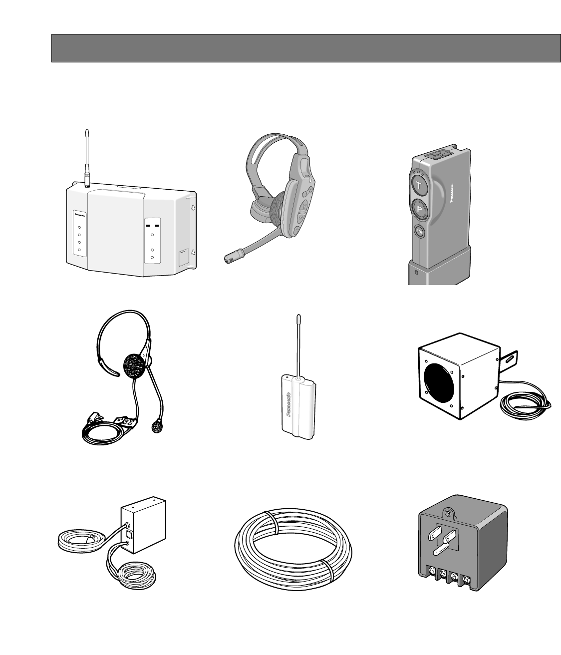
PANASONIC WX-CC2010 SERIES SYSTEM PARTS AND ACCESSORIES
■All in One Headset
WX-CH2050 ■Order Taker Unit
WX-CT2020
■Order Taker Unit Case
WX-CT2022
■Speaker Microphone
WX-C550
■Transceiver
WX-CT2030
■Battery Charger
For WX-CH2050: 2050CH
For WX-CT2020: 2020CH
■Vehicle Detector 917-1
(Locally Procured)
■Rechargeable Battery
For WX-CH2050: 2050BAT or 2051BAT
For WX-CT2020: 2020BAT
■Speaker/Loop Cable Kit
WX-C687
A
B
WX-CT2020
WX-CC2010
TRANSCEIVER
MONITOR
1
2
3
4
ULTRAPLEX II
POWER
VEHICLE
PRESENT
DNRDNR
A
B
■Center Module
WX-CC2010
■Headset
WX-C1027A
■Power Transformer
WX-C516
Note: Illustrations may differ from actual products.
8
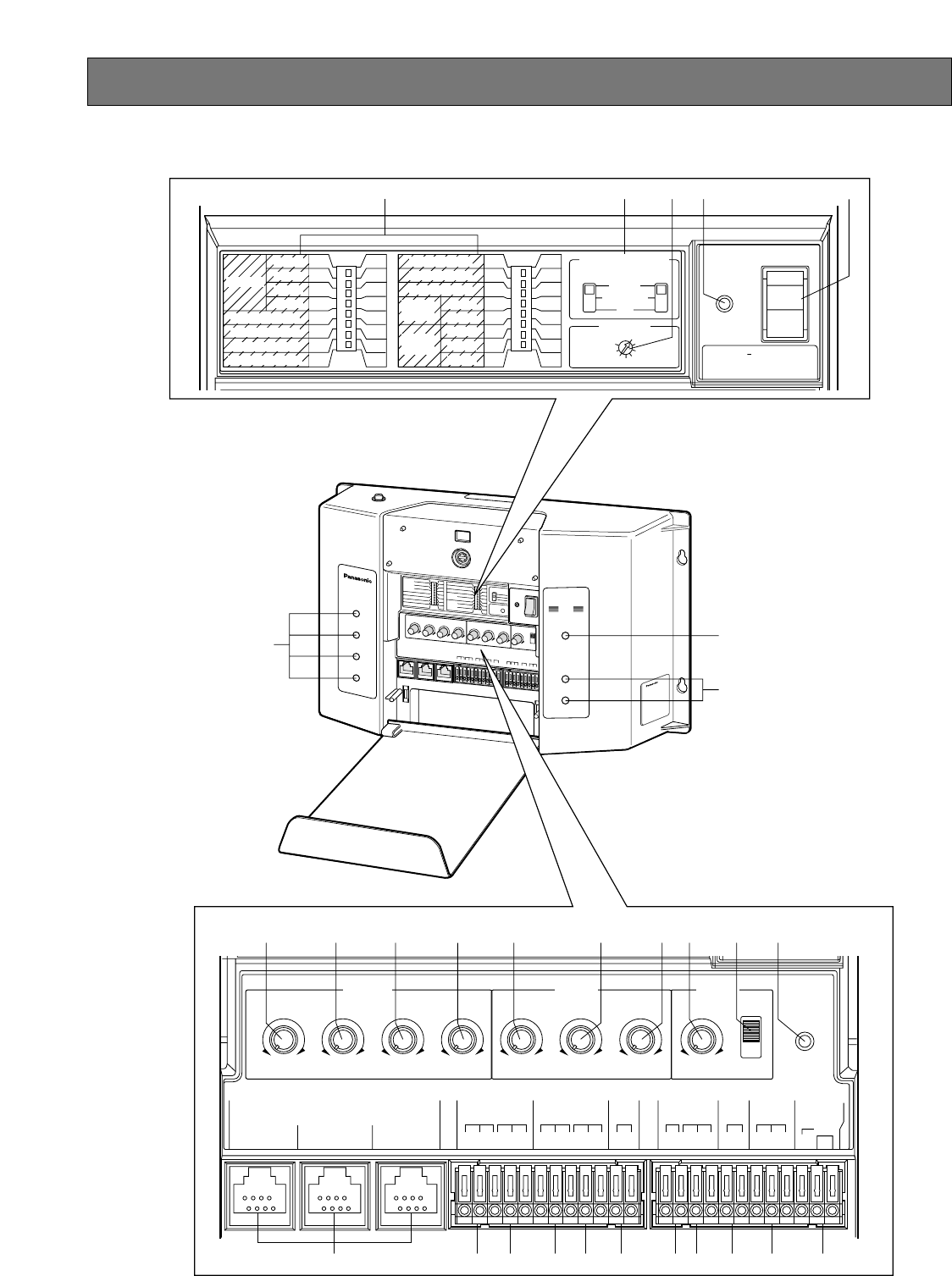
MAJOR OPERATING CONTROLS AND THEIR FUNCTIONS
■WX-CC2010 Center Module
WX-CC2010
TRANSCEIVER
MONITOR
1
2
3
4
ULTRAPEX II
POWER
VEHICLE
PRESENT
DNRDNR
A
B
ULTRAPLEX II
POWER
VEHICLE
PRESENT
DNRDNR
A
B
o
y
!0 !1 !2 !3 !4 !5 !6 !7 !8
u
i
!9
q w rt
OFF
OFF
OFF
OFF
A
LINE
B
OFF
ON
ON
ON
ON
A+B
G/MIC
A
ON
REMOTE
REMOTE SP A
AUX IN SEL
AUX OUT SEL
TALK MONITOR
AUX IN
TALK
PAGE
BEEP
SDT
OFF
USA
OFF
OFF
OFF
OFF
OFF
DDT
AB
ON
CND
ON
ON
ON
ON
ON
D.THROUGH
MANAGER
USA/CANADA
T/B
LEVEL
DNR
EFFECT
TBC1
TBC2
DNR1
DNR2
DNR3
VEHICLE DETECTOR
CH SELECT
NORMAL
OFF
OVERRIDE ON
1
2
3
4
5
6
7
8
POWER
ON
OFF
CAUTION
USE WITH SPECIFIED
EQUIPMENT SEE ITS MANUAL
BEFORE CONNECTING
CIRCUT
PROTECTOR
O / T
TALK LOCK
RELEASE
OUTPUT
010010010010
A
MENU SP
BA
REMOTE SP
B
INPUT BEEP
010 010010010
A
MENU MIC
B
A
B
REMOTE
SPA
REMOTE
SPB
AUX
AUX IN
DAY
LOAD
NIGHT
TRANSCEIVER
234
HHCC
GND
MENU
A
MIC
SP
8 Ω
HHCC HC
GND
H
GND
G/MIC
PTT
TRANSFORMER
12V
AC
V/DET
IN
COM
H
GND
GND
MENU
B
MIC
IN
COM
IN
SP
8 Ω
INPUT
e
@0 @1 @2 @3 @4 @5 @6 @7 @8 @9
9
Notes:
•The following switches and terminals should be used
by qualified service personnel or system installers
only.
•To change the setting of the following switches, turn
off the power of the center module, then turn it back
on.
qAuxiliary Input On/Off Switch (REMOTE AUX IN,
ON/OFF)
Set this switch to ON to output the audio (that has
been input from the AUX INPUT terminals) to the
REMOTE SP terminals.
Talk On/Off Switch (REMOTE TALK, ON/OFF)
To monitor the conversation between the store person-
nel and customer with the remote speaker, set this
switch to ON.
Page On/Off Switch (REMOTE PAGE, ON/OFF)
To monitor the conversation among the store person-
nel with the remote speaker, set this switch to ON.
Beep On/Off Switch (REMOTE BEEP, ON/OFF)
Set this switch to ON to output beep sounds to the
remote speakers.
Remote Speaker A Switch (REMOTE SP A)
The menuboard microphone(s) to output the sound(s)
from Remote Speaker A is [are] selected with this
switch.
A: Remote Speaker A outputs the sound of
Menuboard Microphone A.
A + B: Remote Speaker A outputs the mixed sound of
Menuboard Microphone A and B.
Auxiliary Input Selection Switch
(AUX IN SEL, G MIC*/LINE)
* "G MIC" is marked as "G/MIC" on the switch panel.
This switch selects the auxiliary input level.
G MIC (Gooseneck Microphone)
This can be used as a wired system.
Input : -62 dBV, balanced
LINE
Input : -20 dBV, balanced
AUX Output Selection Switch (AUX OUT SEL)
The menuboard speaker to send the auxiliary input is
selected with this switch.
A: The auxiliary input is sent to the Menuboard
Speaker A.
B: The auxiliary input is sent to the Menuboard
Speaker B.
Talk Monitor On/Off Switch (TALK MONITOR,
ON/OFF)
This switch should be normally set to OFF.
Consult your servicing dealer before attempting to
change this switch.
D-THROUGH Selection Switch (D. THROUGH,
DDT/SDT)
SDT (Single Drive Through) or DDT (Double Drive
Through) is selected with this switch. (Refer to p. 15
OPERATION MODE DESCRIPTIONS for details.)
Manager Switch (MANAGER)
The Manager mode is set to ON or OFF with this
switch. (Refer to p. 15 OPERATION MODE DESCRIP-
TIONS for details.)
USA/Canada Switch (USA/CANADA)
To select a radio frequency suitable for the region, set
this switch as follows.
USA: This setting is available in the United States.
CND: This setting is available in Canada.
Talkback Level Control Switch (T/B LEVEL: TBC1,
TBC2, ON/OFF)
These switches are used for the talkback level setting
of the order taker unit.
Change the settings if the talkback level is too high.
Note: These settings are activated when the DNR
switch is set to ON.
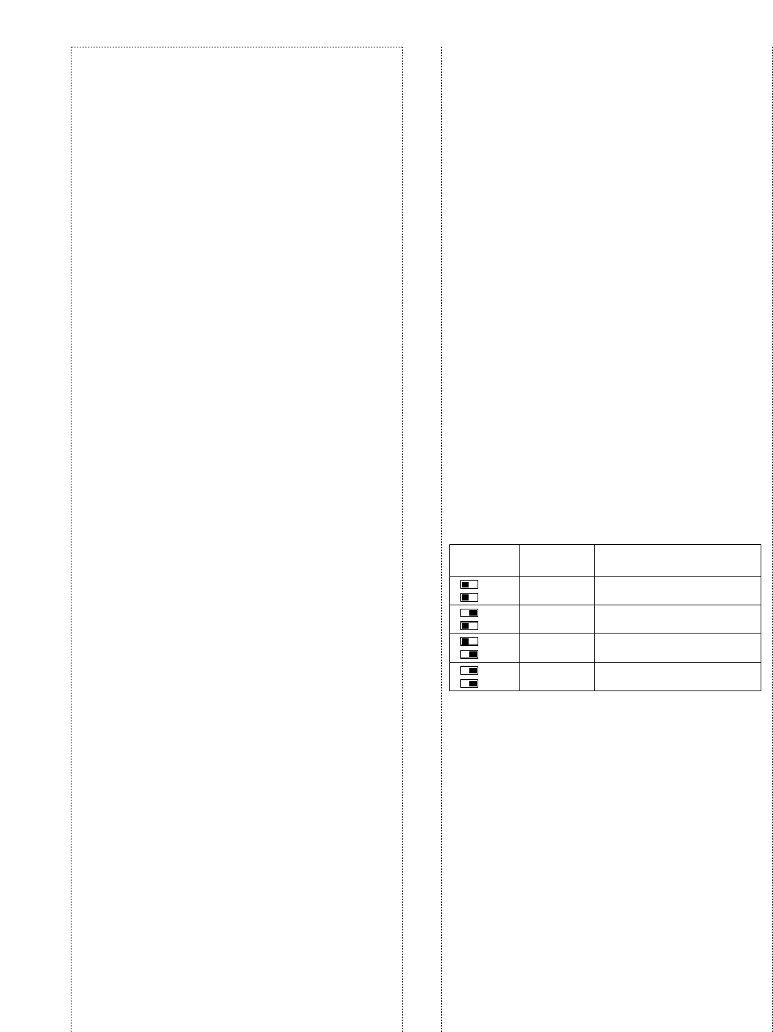
DNR (Digital Noise Reduction) Effect Level Control
Switch
(DNR EFFECT: DNR1, DNR2, DNR3, ON/OFF)
These switches are used for the noise reduction level
setting.
The more the noise is reduced, the lower the sound
quality will be. The following table shows the relation-
ship between noise reduction level and sound quality.
Note: No setting should be done other than shown in
the table.
Setting Talkback
Level
TBC1
TBC2
TBC1
TBC2
TBC1
TBC2
TBC1
TBC2
Normally set to this position.
Talkback level set to 50 %.
Talkback level set to 35 %.
Talkback level set to 25 %.
Remarks
–6 dB
–9 dB
–12 dB
– Talkback is off.

10
tPower On/Off Switch (POWER, ON/OFF)
This switch turns the power of the center module on
and off.
yTransceiver monitor Indicator
(TRANSCEIVER MONITOR 1 to 4)
Red: When the order taker unit is in the Talk PTT/Talk
Lock mode, the indicator lights up in red.
Green: When the order taker unit is in the Page PTT/
Page Lock mode, the indicator lights up in green.
uPower Indicator (POWER)
This indicates that the power of center module is on.
iVehicle Detector Lane A and B Indicators
(VEHICLE PRESENT A/B) (Amber)
This indicates that a vehicle has been detected.
oMenuboard Speaker A Volume Control
(MENU SP A, 0 to 10)
This control sets the output level of Menuboard
Speaker A to the optimum level for speaking to the cus-
tomer.
Notes:
•Adjust this control after you set the VEHICLE
DETECTOR A switch to OVERRIDE ON and the
vehicle detector indicator lights up. Otherwise, you
cannot adjust the volume level.
•The line marked on this control is a standard posi-
tion for this adjustment. Adjust this control to the
suitable position so that feedback does not occur.
!0 Menuboard Speaker B Volume Control
(MENU SP B, 0 to 10)
This control sets the output level of Menuboard
Speaker B to the optimum level for speaking to the cus-
tomer.
Notes:
•Adjust this control after you set the VEHICLE
DETECTOR B switch to OVERRIDE ON and the
vehicle detector indicator lights up. Otherwise, you
cannot adjust the volume level.
•The line marked on this control is a standard posi-
tion for this adjustment. Adjust this control to the
suitable position so that feedback does not occur.
!1 Remote Speaker A Volume Control
(REMOTE SP A, 0 to 10)
This control sets the output level of Remote Speaker A
to the optimum level.
Notes:
•Adjust this control after you set the VEHICLE
DETECTOR A switch to OVERRIDE ON and the
vehicle detector indicator lights up. Otherwise, you
cannot adjust the volume level.
•The line marked on this control is a standard posi-
tion for this adjustment.
Adjust this control to the suitable position so that
feedback does not occur.
wVehicle Detector Normal/Override On/Off Switches
(VEHICLE DETECTOR A/B, NORMAL/OVERRIDE
ON/OFF)
NORMAL: The vehicle detector turns on only when a
vehicle is detected at the menu board. When the
detector is turned on, a beep tone is heard in the
headset. After the beep tone, the menuboard
speaker turns on to allow the communication with
the customer. When the vehicle leaves, the vehicle
detector turns off.
OVERRIDE ON: The vehicle detector is always turned
on.
OFF: Vehicles are not detected at the menuboard. No
beep tone is heard in the headset, and the
menuboard speaker remains off.
eChannel Group Selection Switch
(CH SELECT, 1 to 8)
This switch selects the group from 8 positions.
Note: Do not set this switch to positions other than 1 to
8. That will result in an error.
rCircuit Protector button (CIRCUIT PROTECTOR)
If excessive current flows to the center module, the cir-
cuit protector is triggered. When this button is sticking
out, turn off the POWER switch, press this CIRCUIT
PROTECTOR button, and turn on the POWER switch
again.
If the circuit protector is soon triggered again, consult
your dealer or authorized service center for assistance.
Channel Monitor
Channel Monitor is the mode to check if other devices
have already used the desired channel at the time of
the installation. The following is how to activate Channel
Monitor.
When you set the POWER switch to ON while holding
down the O/T TALK LOCK RELEASE switch, Channel
Monitor is activated. At the time, Channel Monitor is
activated for TR1. Whenever the O/T TALK LOCK
RELEASE switch is pressed, the activated channel is
changed to TR2 →TR3 →TR4 →TR1. To return to the
default mode, turn off and on the power again with the
POWER switch.
Setting Noise
Reduction
Level
DNR1
DNR2
DNR3
DNR1
DNR2
DNR3
DNR1
DNR2
DNR3
DNR1
DNR2
DNR3
No DNR processing
For a relatively quiet
environment
Remarks
Sound
Quality
High
Normal
Low
Low
Normal
High
For a very noisy environment
Not recommended because it
affects sound quality.
For a general environment
This setting is recommen-
ded.

11
!2 Remote Speaker B Volume Control
(REMOTE SP B, 0 to 10)
This control sets the output level of Remote Speaker B
to the optimum level.
Notes:
•Adjust this control after you set the VEHICLE
DETECTOR B switch to OVERRIDE ON and the
vehicle detector indicator lights up. Otherwise, you
cannot adjust the volume level.
•The line marked on this control is a standard posi-
tion for this adjustment.
Adjust this control to the suitable position so that
feedback does not occur.
!3 Menuboard Microphone A Volume Control
(MENU MIC A, 0 to 10)
This control sets the input level of Menuboard
Microphone A to the optimum level.
Notes:
•Adjust this control after setting the VEHICLE
DETECTOR A switch to OVERRIDE ON and the
vehicle detector indicator lights up. Otherwise, you
cannot adjust the volume level.
•The line marked on this control is a standard posi-
tion for this adjustment. Adjust this control to the
suitable position so that feedback does not occur.
!4 Menuboard Microphone B Volume Control
(MENU MIC B, 0 to 10)
This control sets the input level of Menuboard
Microphone B to the optimum level.
Notes:
•Adjust this control after setting the VEHICLE
DETECTOR B switch to OVERRIDE ON and the
vehicle detector indicator lights up. Otherwise, you
cannot adjust the volume level.
•The line marked on this control is a standard posi-
tion for this adjustment. Adjust this control to the
suitable position so that feedback does not occur.
!5 Auxiliary Input Level Control (AUX IN, 0 to 10)
This controls the input level of the AUX INPUT termi-
nals.
!6 Vehicle Detector Beep Volume Control
(BEEP, 0 to 10)
This control sets the vehicle-detection beep tone for the
order taker unit to the optimum level. When the VEHI-
CLE DETECTOR A/B switch is set to NORMAL, turning
this control changes the beep tone level of the remote
speaker.
!7 Day/Night Selection Switch (DAY/NIGHT)
In the Day mode, you will not hear the beep tone of the
other lane in the headset if the vehicle detector is on
and you press the button T of the order taker unit.
State of lane
Vehicle detec-
tor at Lane A is
ON.
Vehicle detec-
tor at Lane B is
ON.
A Beep A
(indicates that a
vehicle has ar-
rived at Lane A.)
Day mode
Order
taker unit Night mode
Beep A
B––
A––
B Beep B
(indicates that a
vehicle has ar-
rived at Lane B.)
Beep B
Vehicle detec-
tors of both
lanes are ON.
A Beep C →X Beep C →B
(indicates
that a vehi-
cle has
arrived at
Lane B.)
B Beep C →X Beep C →B
(indicates
that a vehi-
cle has
arrived at
Lane A.)
!8 Order Taker Unit Talk Lock Release Switch
(O/T TALK LOCK RELEASE)
This switch is used to release temporarily the talk lock
mode of the order taker unit.
!9 Transceiver LAN Jack (TRANSCEIVER)
This jack is used for the connection with WX-CT2030
Transceiver.
@0 Menuboard Microphone A Terminals
(MENU A MIC: H, C, GND)
These terminals are used for the connection with
Menuboard Microphone A (Speaker Microphone WX-
C550).
The audio level is – 61 dBV, 8 ohms, balanced.
@1 Menuboard Speaker A Terminals
(MENU A SP 8 Ω: H, C, GND)
These terminals are used for the connection with
Menuboard Speaker A (Speaker Microphone WX-
C550).
The audio level is 8 Ω, 3 W, unbalanced.
@2 Menuboard Microphone B Terminals
(MENU B MIC: H, C, GND)
These terminals are used for the connection with
Menuboard Microphone B (Speaker Microphone WX-
C550).
The audio level is – 61 dBV, 8 ohms, balanced.
In the Night mode, you will hear the beep tone of either
lane in the headset if the vehicle detector is on. Once
you press the button T, you will no longer hear your
lane’s beep tone. However, you will continue to hear
the other side’s beep tone if the other side vehicle
detector is on, until the talk button of the other side’s
order taker unit is pressed.

12
@3 Menuboard Speaker B Terminals
(MENU B SP 8 Ω: H, C, GND)
These terminals are used for the connection with
Menuboard Speaker B (Speaker Microphone WX-
C550).
The audio level is 8 Ω, 3 W, unbalanced.
@4 Remote Speaker A Terminals
(REMOTE SP A: H, GND)
These terminals are used for the connection with
Remote Speaker A.
The audio level is 8 Ω, 3 W, unbalanced.
Note: The remote speaker is a locally procured acces-
sory.
@5 Remote Speaker B Terminals
(REMOTE SP B: H, GND)
These terminals are used for the connection with
Remote Speaker B.
The audio level is 8 Ω, 3 W, unbalanced.
Note: The remote speaker is a locally procured acces-
sory.
@6 Auxiliary Input Terminals (AUX INPUT: H, C, GND)
These terminals are used for the connection with the
line or the connection with a gooseneck microphone.
Note: When connecting the gooseneck microphone,
set the AUX IN SEL switch to G/MIC.
@7 Gooseneck Microphone PTT Terminals
(G/MIC PTT: IN, COM)
These terminals are used for the connection with the
PTT cable of a gooseneck microphone (locally pro-
cured).
@8 Vehicle Detector A and B Terminals
(V/DET A/B: IN, COM)
These terminals are used for the connection with the
output terminal of vehicle detector.
@9 Transformer Terminals
(TRANSFORMER 12V AC: GND, LOAD)
These terminals are used for the connection with WX-
C516 Power Transformer.
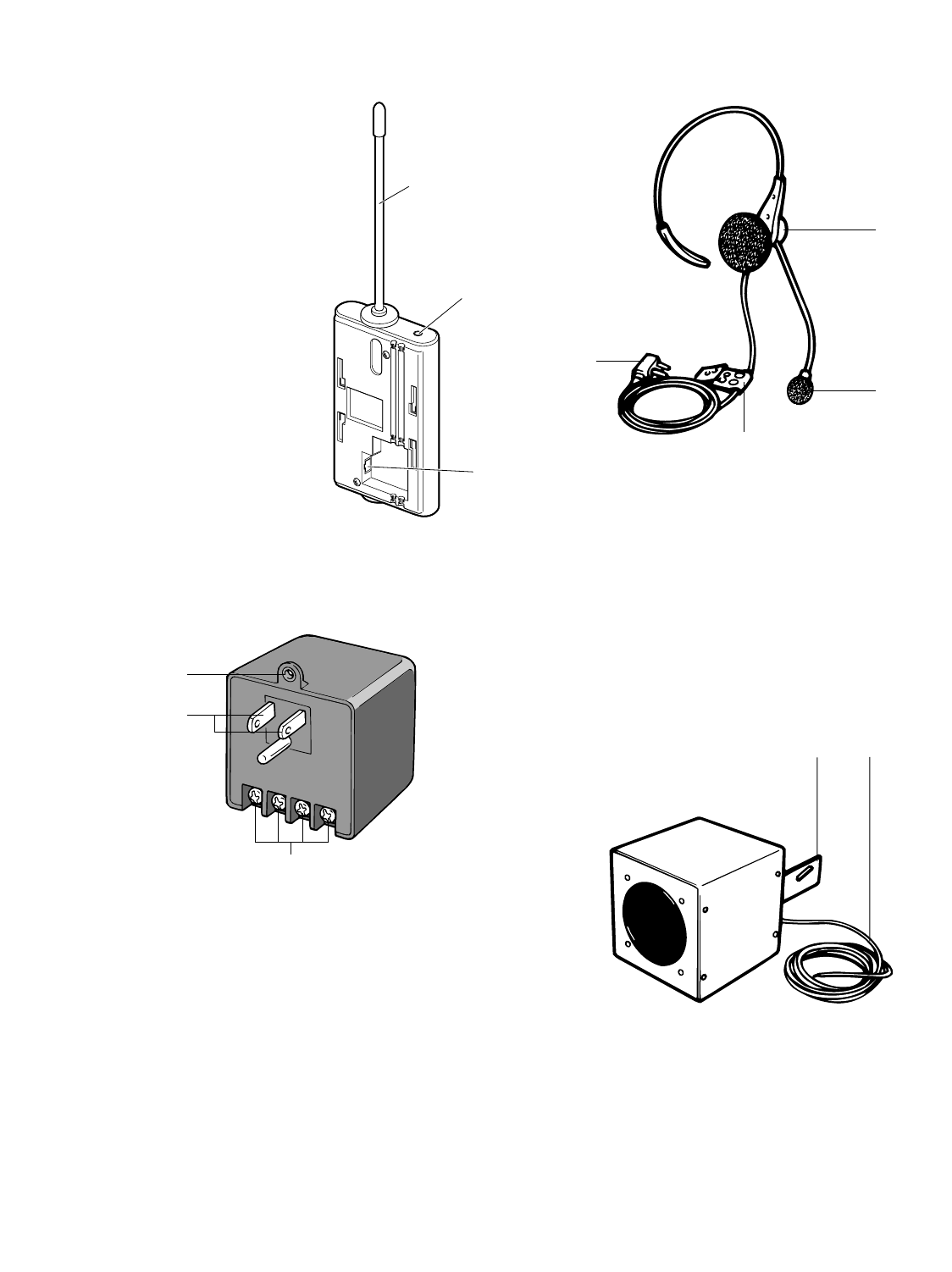
13
■WX-CT2030 Transceiver
#0 Antenna
#1 Power LED Indicator
#2 Center Module Connector
■WX-C516 Power Transformer
#3 Mounting Hole
This hole is used for mounting the power transformer
onto the wall plates.
#4 Power Plug
To prevent fire or electrical shock, connect this directly
to a 3-plug grounded receptacle of 120 V AC, 60Hz.
#5 Output terminal (SPARE, AC, AC, GND)
12 V AC, 1 600 mA (UL Listed) is provided at the two
terminals (indicated as "AC") to be used for the center
module.
Caution:
Be sure to connect the wire between the GND
(GROUND) of this terminal and that in the trans-
former terminal on the center module.
To prevent fire or electrical shock, the UL listed
power supply cord (Style SVT) should be used for
the cable for 12 V AC terminal.
■WX-C1027A Headset
#6 Earphone
#7 Microphone
#8 Cable Clips
Use these clips to attach the cable to your uniform.
#9 Headset Plug
■WX-C550 Speaker Microphone
$0$1
#3
#4
#5
#6
#7
#8
#9
#0
#1
#2
$0 Input Cord
A pigtail cord is provided for the speaker input. Its
length is approx. 3 meters.
$1 Mounting Bracket
AU-type mounting bracket with screw holes is provid-
ed as a standard accessory with the WX-C550.
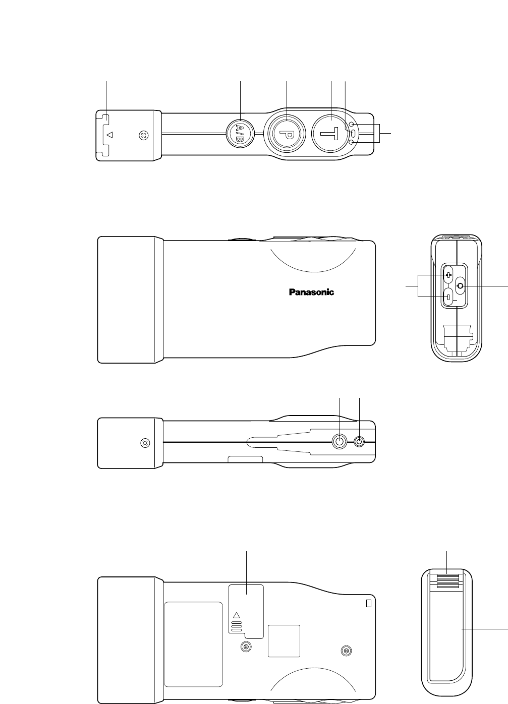
14
■WX-CT2020 Order Taker Unit
EJECT
WX-CT2020
AB
PWRVOL
$8 $9
%3
%0 %1
%2 $2
$7
$2 $3 $4 $5 $6

15
$2 Battery Lock (EJECT)
$3 A/B Channel Selection Button (A/B)
$4 Page Button (P)
$5 Talk Button (T)
$6 Power Indicator
$7 Channel Indicator
$8 Volume Control Buttons (VOL AB)
$9 Power Button
%0 Earphone Input Jack
%1 Microphone Input Jack
%2 Switch Pocket
%3 Battery (Optional accessory)

16
WX-CC2010
WX-CC2010
TRANSCEIVER
MONITOR
1
2
3
4
ULTRAPLEX II
POWER
VEHICLE
PRESENT
DNR
DNR
A
B
:Communication area
WX-CT2020 / WX-CH2050 can receive
the transmission signals from WX-CC2010.
:Non-communication area
WX-CT2020 / WX-CH2050 cannot receive
the transmission signals from WX-CC2010.
Center Module Dip Switch Setting
[D·THROUGH]: SDT
[MANAGER]: OFF
WX-CT2020 / WX-CH2050
Dip Switch Setting
[D·THROUGH]: SDT
[MANAGER]: OFF
[Role Assignment]: Assistant
[Area Expansion]: Normal
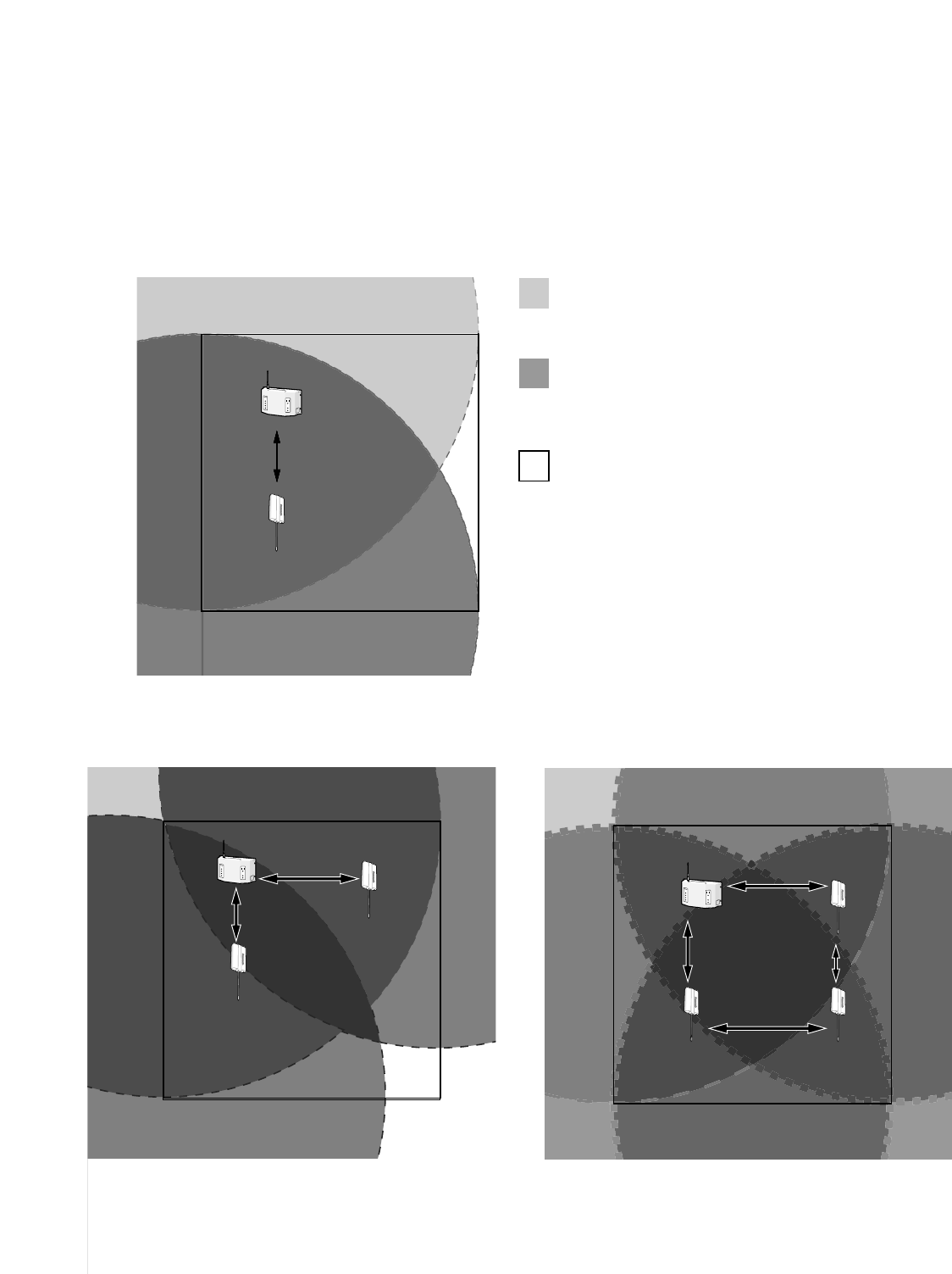
OPERATION MODE DESCRIPTIONS
The following descriptions are operation modes available using WX-CC2010 Center Module and WX-CT2030 Transceiver.
Notes:
•"User" mentions a person using WX-CT2020 Order Taker Unit or WX-CH2050 All-in-One Headset.
•When more than one user exists in the same area, the nearest user will receive the transmission signal from WX-CC2010 /
WX-CT2030.
■Operation Mode 1 (Same as WX-C1011 and WX-C1020 System)
This is the basic operation mode that is also employed by current models other than WX-CC2010.
•In the TALK mode, a user can communicate with a customer at the menu board.
•In the PAGE mode, two users can communicate with each other.
17
* w to rshows the transceiver No.
It is the same as TRANSCEIVER jack No.
of WX-CC2010.
30.48 m
{100 ft.}
or more
WX-CC2010
TRANSCEIVER
MONITOR
1
2
3
4
ULTRAPLEX II
POWER
VEHICLE
PRESENT
DNR
DNR
A
B
WX-CT2020 / WX-CH2050
Dip Switch Setting
[D·THROUGH]: SDT
[MANAGER]: OFF
[Role Assignment]: Assistant
[Area Expansion]: Expand
:Communication area
WX-CT2020 / WX-CH2050 can receive
the transmission signals from WX-CT2030.
:Communication area of WX-CC2010
WX-CT2020 / WX-CH2050 can receive
the transmission signals from WX-CC2010.
:Non-communication area
Center Module Dip Switch Setting
[D·THROUGH]: SDT
[MANAGER]: OFF
WX-CC2010
WX-CT2030
w*
WX-CC2010 x 1, WX-CT2030 x 1
■Operation Mode 2 (Area Expansion)
By using WX-CT2030 Transceiver, you can expand the communication area of Operation Mode 1.
•Up to three WX-CT2030 can be added.
•The number of users who can simultaneously communicate in the TALK / PAGE mode depends on the total number of
transceivers (WX-CC2010 x 1 + WX-CT2030 x ∗).
Note: "∗" is the number of WX-CT2030.
WX-CC2010
TRANSCEIVER
MONITOR
1
2
3
4
ULTRAPLEX II
POWER
VEHICLE
PRESENT
DNRDNR
A
B
30.48 m
{100 ft.}
or more
WX-CC2010
WX-CT2030
w
WX-CT2030
e
30.48 m {100 ft.}
or more
WX-CC2010 x 1, WX-CT2030 x 2
WX-CC2010
TRANSCEIVER
MONITOR
1
2
3
4
ULTRAPLEX II
POWER
VEHICLE
PRESENT
DNRDNR
A
B
WX-CC2010 WX-CT2030
e
WX-CT2030
w
WX-CT2030
r
30.48 m
{100 ft.}
or more
30.48 m
{100 ft.}
or more
30.48 m
{100 ft.}
or more
30.48 m
{100 ft.}
or more
WX-CC2010 x 1, WX-CT2030 x 3

18
■Operation Mode 3 (Manager Mode)
In this operation mode, you can assign the role of manager / assistant personnel to each user.
•The manager has the communication priority to assistant personnel. The manager can cut into a conversation with a cus-
tomer even when one of assistant personnel is communicating with the customer in the TALK mode.
•In the PAGE mode, the manager can communicate with one of the assistant personnel.
Note: Set WX-CT2030 Transceiver in the area that covers the moving range of the manager.
WX-CC2010
TRANSCEIVER
MONITOR
1
2
3
4
ULTRAPLEX II
POWER
VEHICLE
PRESENT
DNR
DNR
A
B
WX-CC2010
WX-CT2030
w*
:Communication area for Manager
WX-CT2020 / WX-CH2050 can receive
the transmission signals from WX-CT2030.
:Communication area for Manager / Assistant Personnal
• WX-CT2020 / WX-CH2050 for the manager
can receive the transmission signals from WX-CT2030.
• WX-CT2020 / WX-CH2050 for the assistant personnel
can receive the transmission signals from WX-CC2010.
• The manager has the communication priority.
:Non-communication Area
Center Module Dip Switch Setting
[D·THROUGH]: SDT
[MANAGER]: ON
WX-CT2020 / WX-CH2050 Dip Switch Setting [Manager]
[D·THROUGH]: SDT
[MANAGER]: ON
[Role Assignment]: Manager
[Area Expansion]: Normal
WX-CT2020 / WX-CH2050 Dip Switch Setting [Assistant]
[D·THROUGH]: SDT
[MANAGER]: ON
[Role Assignment]: Assistant
[Area Expansion]: Normal
* w shows the transceiver No.
It is the same as TRANSCEIVER jack No.
of WX-CC2010.
3.05 m
{10 ft.}
or more
19
■Operation Mode 4 (Area Expansion with Manager)
By adding two WX-CT2030 Transceivers (x 1 to the assistant area and x 1 to the manager area), you can expand the commu-
nication areas of Operation Mode 3.
•The number of users who can simultaneously communicate in the TALK / PAGE mode depends on the total number of
transceivers (WX-CC2010 x 1 + WX-CT2030 x ∗).
Note: "∗" is the number of WX-CT2030.
•The manager has the communication priority to assistant personnel. The manager can cut into a conversation with a cus-
tomer even when one of assistant personnel is communicating with the customer in the TALK mode.
Note: Set WX-CT2030 Transceiver (Manager) in the area that covers the moving range of the manager.
WX-CC2010
WX-CT2030
w*
(Manager)
WX-CT2030
e
(Assistant)
WX-CT2030
r
(Manager)
3.05 m {10 ft.}
or more
WX-CC2010
TRANSCEIVER
MONITOR
1
2
3
4
ULTRAPLEX II
POWER
VEHICLE
PRESENT
DNR
DNR
A
B
3.05 m {10 ft.}
or more
Keep the distance of 30.48 m {100 ft.} or more between (1) and (2).
(1): WX-CC2010 / WX-CT2030 w
(2): WX-CT2030 e / r
:Communication area for Manager
WX-CT2020 / WX-CH2050 of the manager can
receive the transmission signals from WX-CT2030.
:Communication area for Manager / Assistant Personnal
• WX-CT2020 / WX-CH2050 for the manager
can receive the transmission signals from WX-CT2030 (Manager).
• WX-CT2020 / WX-CH2050 for the assistant personnel
can receive the transmission signals from WX-CC2010/
WX-CT2030 (Assistant).
• The manager has the communication priority.
:Non-communication area
* w shows the transceiver No.
It is the same as TRANSCEIVER jack No. of WX-CC2010.
Center Module Dip Switch Setting
[D·THROUGH]: SDT
[MANAGER]: ON
WX-CT2020 / WX-CH2050
Dip Switch Setting [Manager]
[D·THROUGH]: SDT
[MANAGER]: ON
[Role Assignment]: Manager
[Area Expansion]: Expand
WX-CT2020 / WX-CH2050
Dip Switch Setting [Assistant]
[D·THROUGH]: SDT
[MANAGER]: ON
[Role Assignment]: Assistant
[Area Expansion]: Expand
20
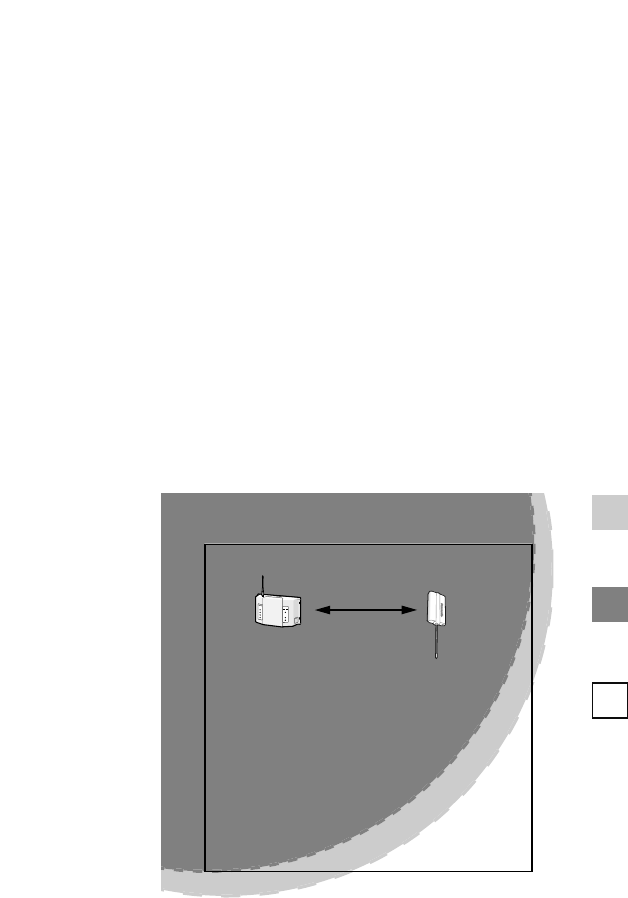
■Operation Mode 5 (Double Drive Through)
This operation mode can be applied for a Double Drive Through composition.
•The number of users who can simultaneously communicate in the TALK / PAGE mode depends on the total number of
transceivers (WX-CC2010 x 1 + WX-CT2030 x ∗).
Note: "∗" is the number of WX-CT2030.
•Communication Area Lane A covers Menuboard A, and Communication Area Lane B covers Menuboard B.
•The users can switch the communication between a customer at Menuboard A/B with the A/B channel selection button.
(Refer to the operating instructions of WX-CT2020 Order Taker Unit or WX-CH2050 All-in-One Headset.)
Note: Communication is not established soon after Communication Area Lane A/B is switched.
Speak to the customer a few seconds after pressing the A/B channel selection button.
WX-CC2010
TRANSCEIVER
MONITOR
1
2
3
4
ULTRAPLEX II
POWER
VEHICLE
PRESENT
DNR
DNR
A
B
WX-CC2010
WX-CT2030
w*
3.05 m {10 ft.}
or more
Center Module Dip Switch Setting
[D·THROUGH]: DDT
[MANAGER]: OFF
WX-CT2020 / WX-CH2050 Dip Switch Setting
[D·THROUGH]: DDT
[MANAGER]: OFF
[Role Assignment]: Assistant
[Area Expansion]: Normal
: Communication Area Lane A
WX-CT2020 / WX-CH2050 in this area can
receive the transmission signals from WX-CC2010.
: Communication Area Lane B
WX-CT2020 / WX-CH2050 in this area can
receive the transmission signals from WX-CT2030.
* w shows the transceiver No.
It is the same as TRANSCEIVER jack No.
of WX-CC2010.
: Non-communication Area
21
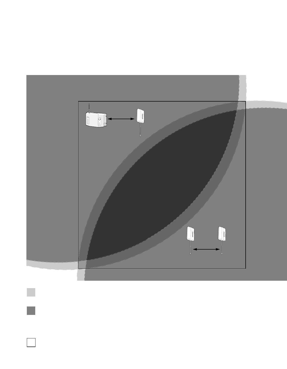
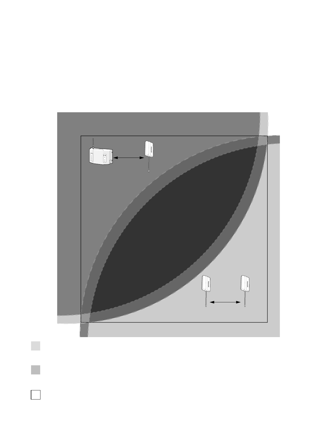
■Operation Mode 6 (Double Drive Through with Area Expansion)
By adding two WX-CT2030 Transceivers (x 1 to the assistant area and x 1 to the manager area), you can expand the commu-
nication areas of Operation Mode 5.
•The number of users who can simultaneously communicate in the TALK / PAGE mode depends on the total number of
transceivers (WX-CC2010 x 1 + WX-CT2030 x ∗).
Note: "∗" is the number of WX-CT2030.
•Communication Area A covers Menuboard A, and Communication Area B covers Menuboard B.
•The users can switch the communication between a customer at Menuboard A/B with the A/B channel selection button.
(Refer to the operating instructions of WX-CT2020 Order Taker Unit or WX-CH2050 All-in-One Headset.)
Note: Communication is not established soon after Communication Area Lane A/B is switched.
Speak to the customer a few seconds after pressing the A/B channel selection button.
WX-CC2010
TRANSCEIVER
MONITOR
1
2
3
4
ULTRAPLEX II
POWER
VEHICLE
PRESENT
DNR
A
B
3.05 m {10 ft.}
or more
3.05 m {10 ft.}
or more
WX-CC2010
(Lane A)
WX-CT2030
w*
(Lane B)
WX-CT2030
e
(Lane A)
WX-CT2030
r
(Lane B)
Keep the distance of 30.48 m {100 ft.} or more between (1) and (2).
(1): WX-CC2010 / WX-CT2030 w
(2): WX-CT2030 e / r
: Communication Area Lane A
WX-CT2020 / WX-CH2050 in this area can
receive the transmission signals from WX-CC2010 / WX-CT2030 (Lane A).
: Communication Area Lane B
WX-CT2020 / WX-CH2050 in this area can
receive the transmission signals from WX-CT2030 (Lane B).
* w shows the transceiver No.
It is the same as TRANSCEIVER jack No.
of WX-CC2010.
: Non-communication Area
Center Module Dip Switch Setting
[D·THROUGH]: DDT
[MANAGER]: OFF
WX-CT2020 / WX-CH2050 Dip Switch Setting
[D·THROUGH]: DDT
[MANAGER]: OFF
[Role Assignment]: Assistant
[Area Expansion]: Expansion
22
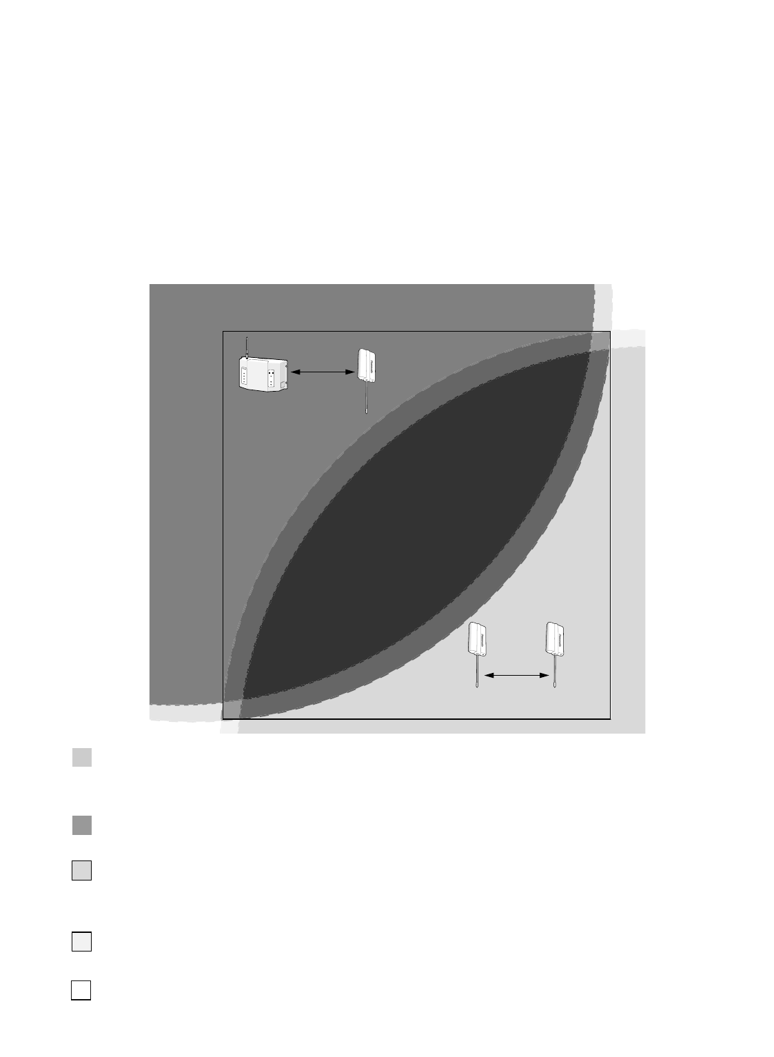
■Operation Mode 7 (Double Drive Through with Manager Mode)
This operation mode can be applied when you assign the role of manager / assistant personnel to each user in a Double Drive
Through composition.
•The number of users who can simultaneously communicate in the TALK / PAGE mode depends on the total number of
transceivers (WX-CC2010 x 1 + WX-CT2030 x ∗).
Note: "∗" is the number of WX-CT2030.
•Communication Area Lane A covers Menuboard A, and Communication Area Lane B covers Menuboard B.
•The users can switch the communication between a customer at Menuboard A/B with the A/B channel selection button.
(Refer to the operating instructions of WX-CT2020 Order Taker Unit or WX-CH2050 All-in-One Headset.)
Note: Communication is not established soon after Communication Area Lane A/B is switched.
Speak to the customer a few seconds after pressing the A/B channel selection button.
•The manager has the communication priority to assistant personnel. The manager can cut into a conversation with a cus-
tomer even when one of assistant personnel is communicating with the customer in the TALK mode.
Note: Set WX-CT2030 (Lane A/B – Manager) in the area that covers the moving range of the manager.
WX-CC2010
TRANSCEIVER
MONITOR
1
2
3
4
ULTRAPLEX II
POWER
VEHICLE
PRESENT
DNR
DNR
A
B
WX-CC2010
(Lane A-Assistant)
3.05 m {10 ft.}
or more
WX-CT2030
e
(Lane A-Manager)
WX-CT2030
r
(Lane B-Manager)
WX-CT2030
w*
(Lane B-Assistant)
3.05 m {10 ft.}
or more
Keep the distance of 3.05 m {10 ft.} or more between (1) and (2).
(1): WX-CC2010 / WX-CT2030 e
(2): WX-CT2030 w / r
: Communication Area Lane A - Manager
WX-CT2020 / WX-CH2050 in this area can receive
the transmission signals from WX-CT2030 (Lane A - Manager).
This area has the communication priority to
the communication area Lane A - Assistant.
: Communication Area Lane A - Assistant
WX-CT2020 / WX-CH2050 in this area can receive
the transmission signals from WX-CC2010 (Lane A - Assistant).
: Communication Area Lane B - Assistant
WX-CT2020 / WX-CH2050 in this area can receive
the transmission signals from WX-CT2030 (Lane B - Assistant).
: Communication Area Lane B - Manager
WX-CT2020 / WX-CH2050 in this area can receive
the transmission signals from WX-CT2030 (Lane B - Manager).
This area has the communication priority to
the communication area Lane B - Assistant.
WX-CT2020 / WX-CH2050 Dip Switch Setting
• Lane A / B - Manager
[D·THROUGH]: DDT
[MANAGER]: ON
[Role Assignment]: Manager
[Area Expansion]: Normal
Center Module Dip Switch Setting
[D·THROUGH]: DDT
[MANAGER]: ON
• Lane A / B - Assistant
[D·THROUGH]: DDT
[MANAGER]: ON
[Role Assignment]: Assistant
[Area Expansion]: Normal
* w shows the transceiver No.
It is the same as TRANSCEIVER jack No. of WX-CC2010.
: Non-communication Area
23
■Installations and Connections
Refer to qualified service personnel for details.
■
Battery Charge and Replacement
(WX-CH2050/WX-CT2020)
Refer to WX-CT2020/WX-CH2050 Operating Instructions for
details.
■Setup Procedures
(WX-CH2050/WX-CT2020)
Note: Setup of WX-CC2010 should only be performed by
qualified service personnel or system installers.
●Opening the Switch Pocket
Refer to WX-CT2020/WX-CH2050 Operating Instructions for
details.
●Channel Group Selection
Refer to p. 25 for the frequency table.
●DIP Switch Setup
This operating instruction only describes what is not men-
tioned in WX-CT2020/WX-CH2050 Operating Instructions.
Settings of SW#2 to #5
The settings of SW#2 to #5 depend on the operation
modes. (Refer to pp. 15 to 21 for details.)
SW#2: For selection of the operation mode (Refer to pp. 15
to 21 for details.)
ON: Applies DDT (Double Drive Thru). If the system
connection is Operation Mode 1 to 4, select this.
OFF: Applies SDT (Single Drive Thru). If the system
connection is Operation Mode 5 to 7, select this.
SW#3: For the activation of the manager mode (Refer to
pp. 17, 18, and 21 for details.)
ON: Activates the manager mode. If the system con-
nection is Operation Mode 3, 4, or 7, select this.
OFF: Activates the normal mode. If the system connec-
tion is Operation Mode 1, 2, 3, 5, or 6, select this.
SW#4: For the role assignment of the person who uses the
order taker unit.
(Refer to pp. 17, 18, and 21 for details.)
ON: The person is assigned as a manager.
OFF: The person is assigned as assistant personnel.
SW#5: For the expansion of communication area (Refer to
pp. 16, 18, and 20 for details.)
ON: Applies the area expansion. When the communi-
cation area is expanded by more than one trans-
ceiver, select this.
OFF: Applies the normal communication area.
●Channel Interference Check
Refer to WX-CT2020/WX-CH2050 Operating Instructions for
details.
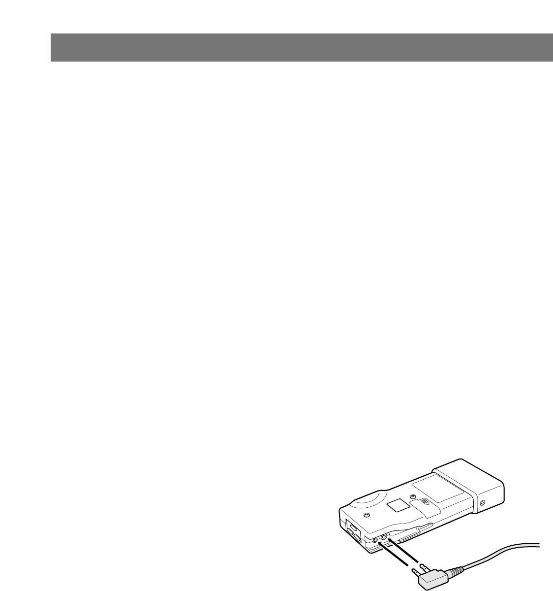
■Preparation
Note: The following procedure applies when using WX-
CT2020 Order Taker Unit and WX-C1027A Headset. If
you use WX-CH2050 All-in-One Headset, refer to the
operating instructions of the headset.
1. After loading a battery into the order taker unit, insert
the headset plug into the earphone input jack and
microphone input jack on the order taker unit.
Note: Confirm that the plug has completely been
inserted into the jack.
PREPARATIONS
24
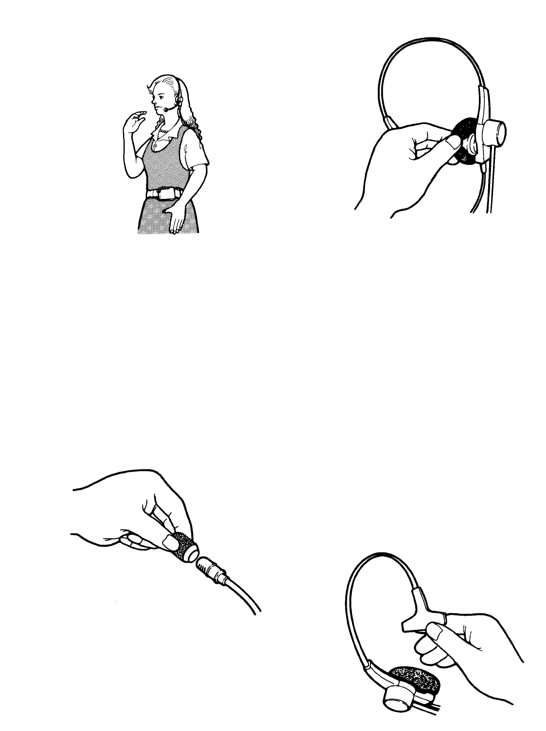
2. Position the microphone boom and wear the order
taker unit case as shown in the figure.
■Maintenance of Headpad
Accessories (WX-C1027A: Non-
Scheduled)
Notes:
•The following procedure applies when using WX-
C1027A Headset. If you use WX-CH2050 All-in-One
Headset, refer to the operating instructions of the
headset.
•Be sure to use the microphone cover/windproof cush-
ion for WX-C1027A Headset. Otherwise, the headset
may be damaged by dust or oil.
Replacement of covers and cushion of head-
set
The earspeaker cover and microphone cover are
washable. After cleaning, make sure they are dry.
Then, return the earspeaker cover and microphone
cover to the headset.
Be careful when you slip it on or off the earpiece.
The earspeaker cover, microphone cover and head-
pad cushion are replaceable for sanitary purposes. To
order WX-C1025A Headset Cover Kit, refer to the deal-
er.
Note: A microphone cover must be used at all times.
Failure to do so can cause debris to accumulate in
the microphone port opening and result in an inop-
erative headset.
Headpad Cushion Replacement
1. Peel off the old cushion.
2. Clean the surface with a warm solution of house-
hold cleaner.
3. Remove the protective tape from the new cushion.
4. Position the new cushion on the headpad and
press in place.
Microphone Cover Replacement
Earspeaker Cover Replacement
Headpad Cushion Replacement

25
Problem
Refer to WX-CT2020/WX-CH2050 Operating Instructions for details.
OPERATING PROCEDURES
Check item
TROUBLESHOOTING
The communication between the order taker units and menu
board cannot be established. • Is the POWER switch on the center module turned on?
(Refer to p. 9.)
• Check the AC power outlet.
• Push the CIRCUIT PROTECTOR button. (Refer to p. 9.)
• Refer to the dealer or qualified service personnel.
• Check to see if the VEHICLE PRESENT indicator of the cen-
ter module lights up when a vehicle drives up the speaker
post or menu board.
• If the indicator does not light up, check the following.
1. Is the vehicle detector plugged in?
2. Check the AC outlet and fuse of the vehicle detector.
If the power and fuse are normal, refer to the qualified ser-
vice personnel.
• Reset the vehicle detector. If the problem still remains,
remove and reinstall the fuse from the detector. (Refer to the
operating instructions of the vehicle detector.)
• If the problem remains even after trying the above, refer to
the dealer or service personnel.
• Confirm that there is no metal obstruction blocking around
the center module.
• It may be necessary to extend one or both antennas to
areas where the reception is error. (Refer to qualified service
personnel or system installers.)
Cannot communicate with the customer at the menu board
(TALK), though the communication among managers/assis-
tant personnel is O.K (PAGE is OK).
A menuboard speaker is always live, even when there is no
car beside the menu board.
TALK (Talk PTT or Talk Lock mode) or PAGE (Page PTT or
Page Lock mode) is unavailable in certain areas.

26
WX-CC2010 Center Module
Operating Frequency: Transmit; 468.6125 MHz - 469.3875 MHz
Receive; 463.6125 MHz - 464.3875 MHz
Type of Emission: F3
Type of Antenna: 1/4 wavelength whip antenna
Power Supply: 12 V AC, 60 Hz (Using WX-C516 Power Transformer)
Power Consumption: 18 W
Menuboard Speaker A and B Output: 3 W, 8 Ω
Remote Speaker A and B Output: 3 W, 8 Ω
Vehicle Detector Input: Normally Open (close contact requires vehicle presence)
Dimensions: 330 mm (W) X 214 mm (H) X 82 mm (D)
{13 in. (W) X 8-7/16 in. (H) X 3-15/64 in. (D)}
Weight (Including Antenna): 1.6 kg(3.5 lbs.)
Ambient operating temperature: –10 °C to +50 °C {14 °F to 122 °F}
Dimensions and weights indicated are approximate.
Specifications are subject to change without notice.
Frequency table
SPECIFICATIONS
CANADAUSA
1
2
3
4
5
6
7
8
9
10
11
12
13
14
15
16
17
18
19
20
21
22
23
24
25
26
27
28
29
30
31
32
463.6125MHz
463.6375MHz
463.6625MHz
463.6875MHz
463.7125MHz
463.7375MHz
463.7625MHz
463.7875MHz
463.8125MHz
463.8375MHz
463.8625MHz
463.8875MHz
463.9125MHz
463.9375MHz
463.9625MHz
463.9875MHz
464.0125MHz
464.0375MHz
464.0625MHz
464.0875MHz
464.1125MHz
464.1375MHz
464.1625MHz
464.1875MHz
464.2125MHz
464.2375MHz
464.2625MHz
464.2875MHz
464.3125MHz
464.3375MHz
464.3625MHz
464.3875MHz
No. CM: Receive Freq.
OT: Transmit Freq.
468.6125MHz
468.6375MHz
468.6625MHz
468.6875MHz
468.7125MHz
468.7375MHz
468.7625MHz
468.7875MHz
468.8125MHz
468.8375MHz
468.8625MHz
468.8875MHz
468.9125MHz
468.9375MHz
468.9625MHz
468.9875MHz
469.0125MHz
469.0375MHz
469.0625MHz
469.0875MHz
469.1125MHz
469.1375MHz
469.1625MHz
469.1875MHz
469.2125MHz
469.2375MHz
469.2625MHz
469.2875MHz
469.3125MHz
469.3375MHz
469.3625MHz
469.3875MHz
CM: Transmit Freq.
OT: Receive Freq.
q
G1 Frequency Group
w
e
r
G2
q
w
e
r
G3
q
w
e
r
G4
q
w
e
r
G5
q
w
e
r
G6
q
w
e
r
G7
q
w
e
r
G8
q
w
e
r
q
G1 Frequency Group
w
e
r
G2
q
w
e
r
G3
q
w
e
r
G4
q
w
e
r
G5
q
w
G6
q
w
G7
q
w
G8
q
w
CM:Center Module (WX-CC2010)
OT:Order Taker Unit (WX-CT2020 or WX-CH2050)

27

PANASONIC CANADA INC.
5770 Ambler Drive, Mississauga,
Ontario, L4W 2T3 Canada (905)624-5010
Panasonic Digital Communications & Security Company
Unit of Matsushita Electric Corporation of America
Information Systems Group
Zone Office
1707 N.Randall Road, Elgin, IL 60123 (866) 472-6767
2003 © Matsushita Electric Industrial Co., Ltd. All rights reserved. NM0803-0 3TR001757AAA Printed in Japan