Panasonic of North America 9TAWX-H3050 All-In-One Headset for DWCS User Manual Manual rev
Panasonic Corporation of North America All-In-One Headset for DWCS Manual rev
UserManual.wiki
>
Panasonic of North America
>
9TAWX H3050 User Manual
Manual rev
Navigation menu
Upload a User Manual
Namespaces
Wiki Guide
HTML
PDF
Info
Views
User Manual
Discussion / Help
Navigation
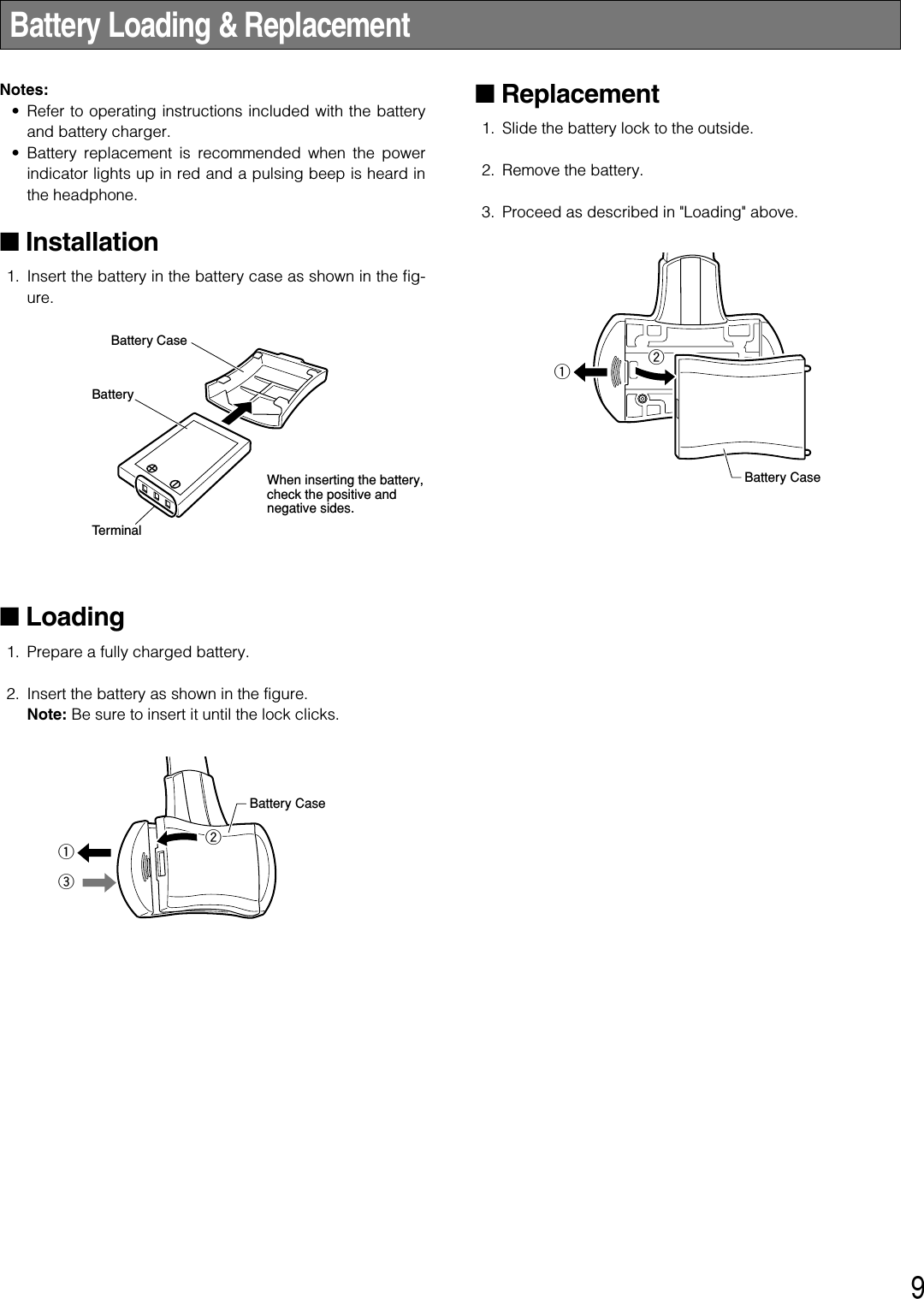
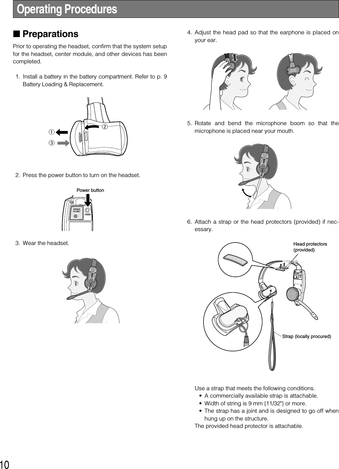
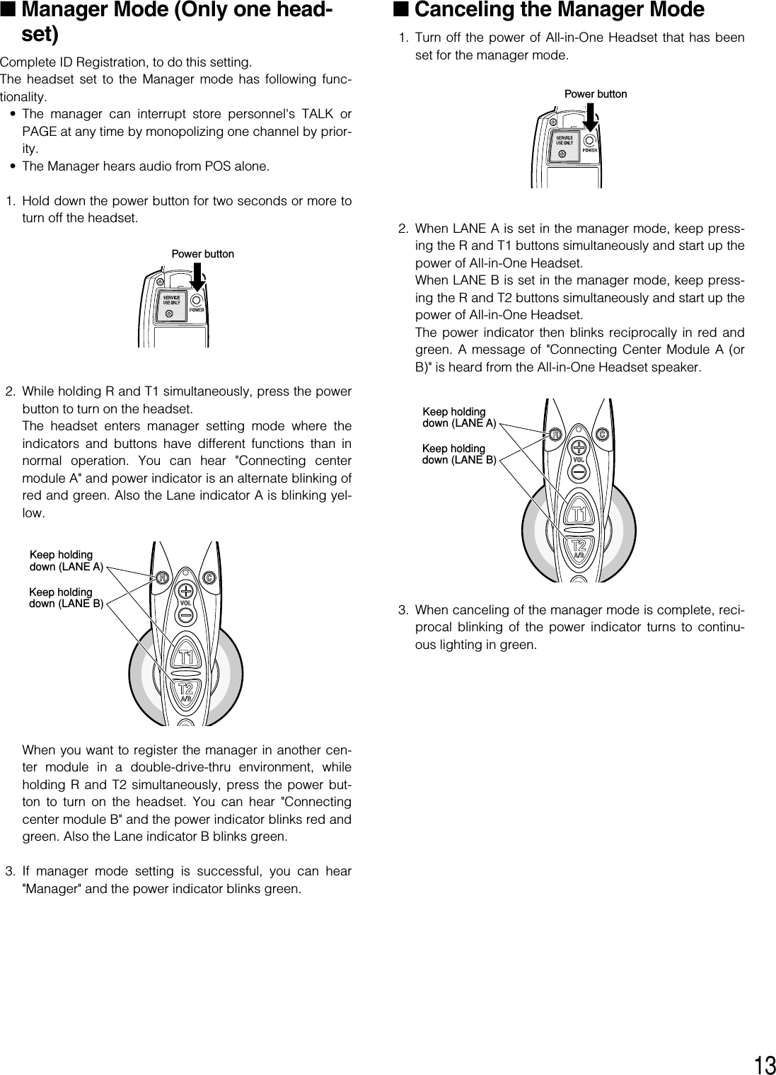
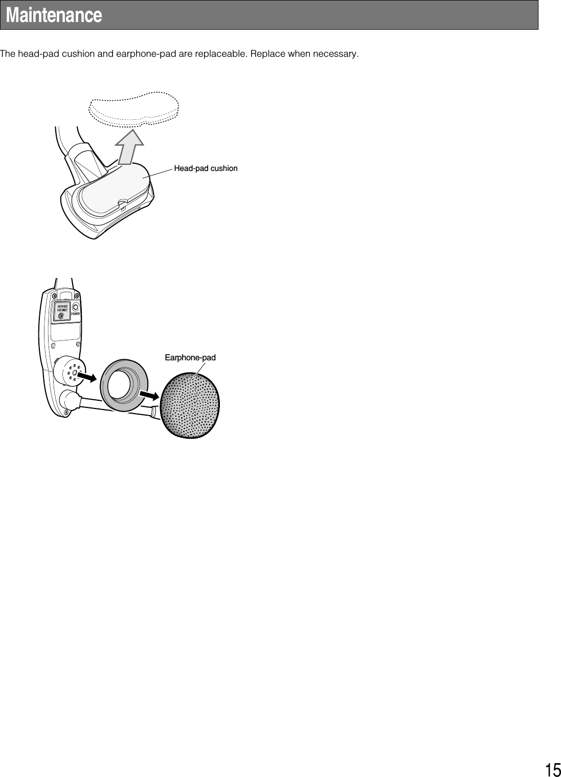
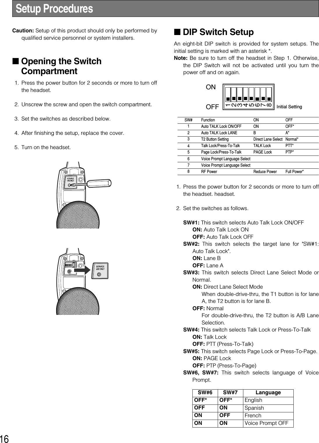
![5Limitation of Liability ................................................................................................................................... 3Disclaimer of Warranty ............................................................................................................................... 3Important Safety Instructions ...................................................................................................................... 4Preface ....................................................................................................................................................... 6Features ...................................................................................................................................................... 6Precautions ................................................................................................................................................. 6Major Operating Controls and Their Functions ........................................................................................... 7Battery Loading & Replacement ................................................................................................................ 9■Installation ............................................................................................................................................ 9■Loading ................................................................................................................................................ 9■Replacement ........................................................................................................................................ 9Operating Procedures ................................................................................................................................ 10■Preparations ......................................................................................................................................... 10■Communications with Customers [TALK] ............................................................................................. 11■Communications with Other Store Personnel [PAGE] .......................................................................... 11■Control of the device control terminals ................................................................................................. 12■Double-Drive-Thru connections ........................................................................................................... 12■Manager Mode (Only one headset) ..................................................................................................... 13■Canceling the Manager Mode ............................................................................................................. 13■Auto-Talk-Lock setup (for only one headset) ....................................................................................... 14Maintenance ............................................................................................................................................... 15Setup Procedures ....................................................................................................................................... 16■Opening the Switch Compartment ....................................................................................................... 16■DIP Switch Setup .................................................................................................................................. 16■ID Registration ...................................................................................................................................... 17■Deletion of ID ....................................................................................................................................... 17Troubleshooting........................................................................................................................................... 18Specifications ............................................................................................................................................. 19Standard Accessories ................................................................................................................................ 20Optional Accessories ................................................................................................................................. 20CONTENTS](https://usermanual.wiki/Panasonic-of-North-America/9TAWX-H3050/User-Guide-1007627-Page-5.png)
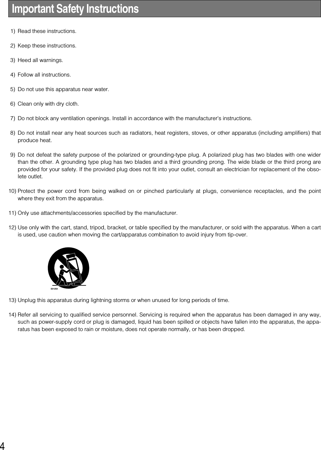
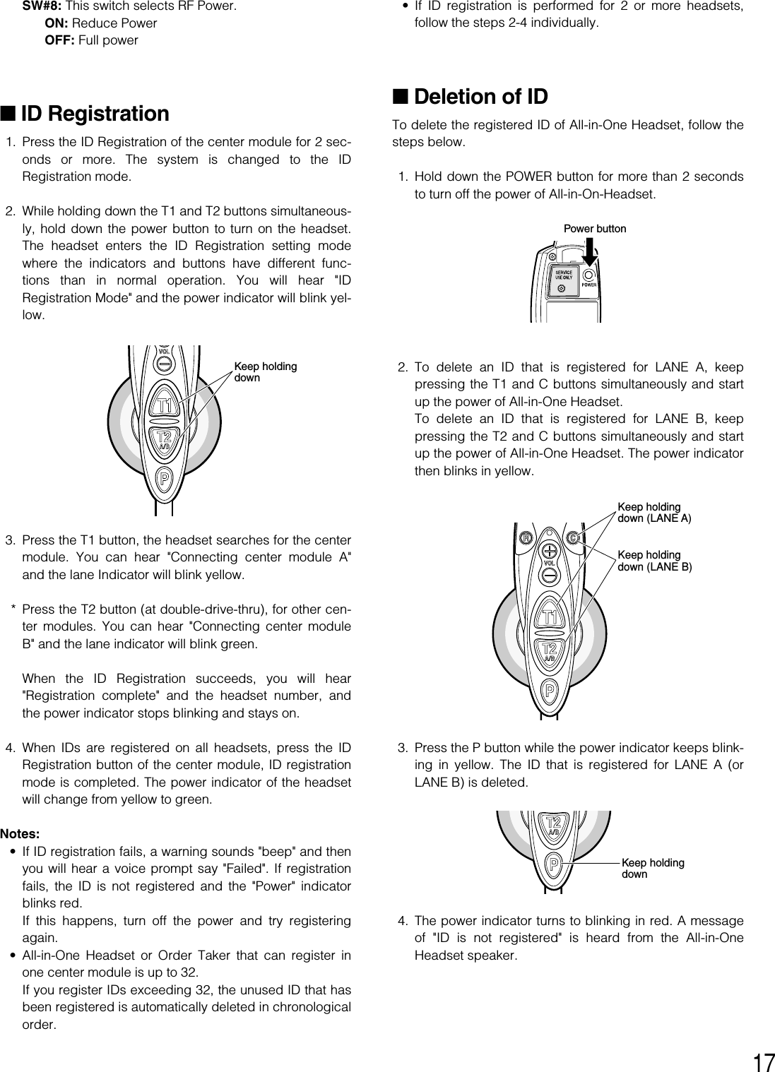
![8qHead Band and Head PadAdjustable to your head by sliding the head pad.wBattery Lock [EJECT]When removing the battery, slide out the lock.When loading a battery, insert the battery until the lockclicks.eBattery Case / Battery (Optional accessory)Refer to p. 6 "Precautions".rHead Pad CushiontSwitch Compart mentDo not open the cover of this compartment. It should beopened only by qualified service personnel or systeminstallers.yPower Button [POWER]Pressing the button will turn the headset on.Pressing the button again for 2 seconds or more will turnthe headset off.uEarphone PadiMicrophone BoomAdjust the microphone position to your mouth by rotatingand bending the boom.oMicrophone!0 Lane IndicatorLights yellow or green to indicate which the lane is inoperation.Yellow: Lane A is selected.Green: Lane B is selected.Yellow blinking: Lane A is being selected, and eitherthe Talk or Page mode is activated.Green blinking: Lane B is being selected, and eitherthe Talk or Page mode is activated.!1 Power IndicatorThe indicator shows the status as follows.Green: Power is supplied and the unit is operating.Green blinking: Power is supplied and Manager modeis activated.Red: The battery requires recharging.Red blinking: ID is not registered, or the center moduleis set to the ID Registration mode.!2 Phone Button [R]Not used.!3 External Device Control Button [C]Press and hold the C button to turn on the externaldevice.!4 Volume Control Buttons [VOL !@]Pressing the buttons will increase or decrease the soundlevel.!5 Talk 1 Button [T1]This button controls communications with the customer.When the button is released, you can hear any customerwho is at the menu-board.While the button is held down in the Press-To-Talkmode, you can speak to the customer.When the button is pressed in the Talk-Lock mode, youcan speak to the customer until you press the button asecond time.!6 Talk 2 / A/B Lane Selection Button [T2, A/B]This button can be set to two functions by the DIP switchsetting. (Refer to p.16 "DIP Switch Setup".)[T2]This button controls communications with the customeron lane B of double-drive-thru.When the button is released, you can hear any customerwho is at the menu board.While the button is held down in the Press-To-Talkmode, you can speak to the customer who is at themenu board.When the button is pressed in the Talk Lock mode, youcan speak to the customer until you press the button asecond time.[A/B]This button switches from Lane A to B and vice versa.The Lane indicator !0 displays the selected Lane in yel-low (A) or green (B).!7 Page Button [P]This button controls communications with store person-nel.When the button is released, you can hear the communi-cations among store personnel.While the button is held down in the Press-To-Pagemode, you can speak to store personnel.When the button is pressed in the Page-Lock mode, youcan speak to the store personnel until you press the but-ton a second time.](https://usermanual.wiki/Panasonic-of-North-America/9TAWX-H3050/User-Guide-1007627-Page-8.png)
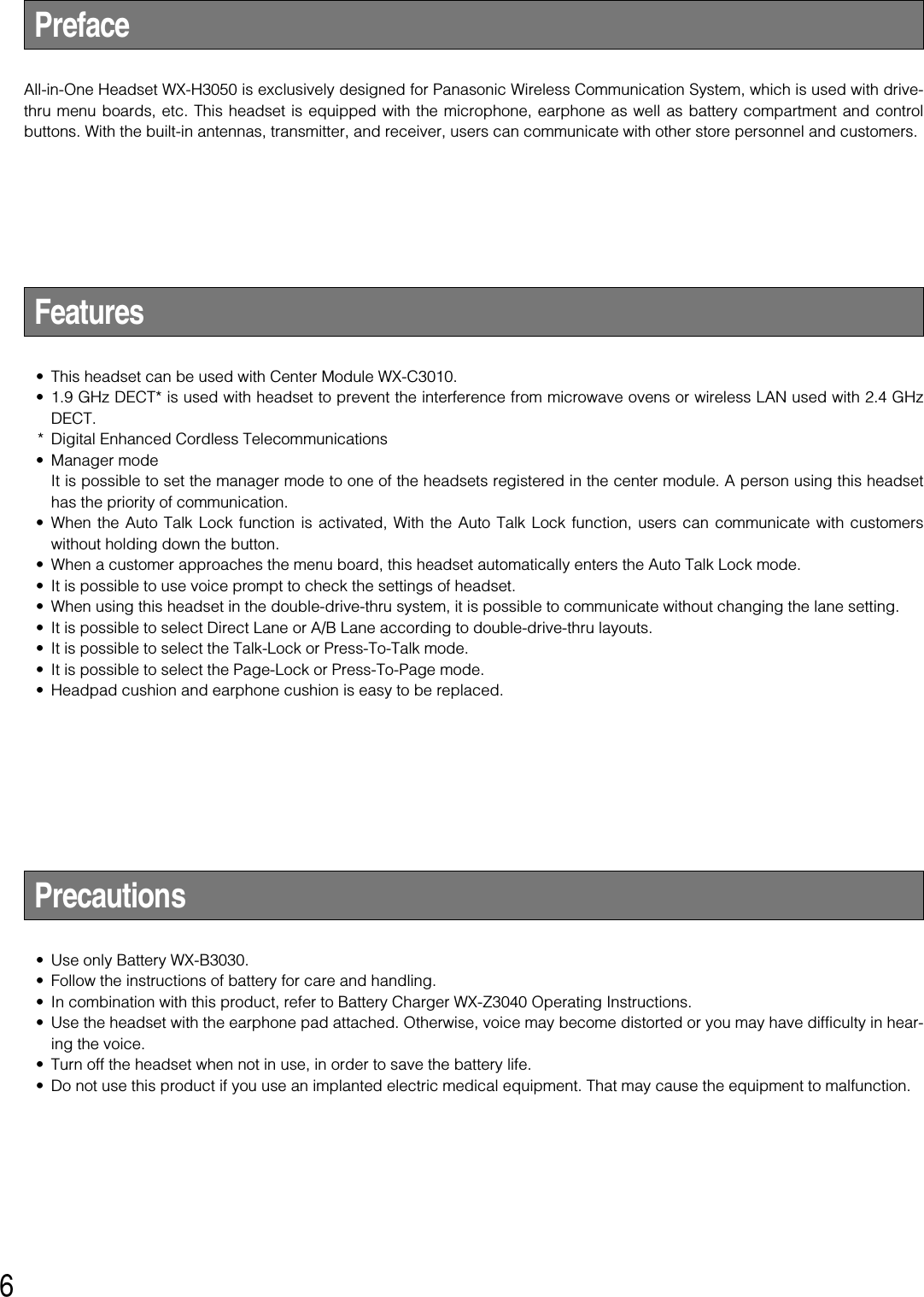
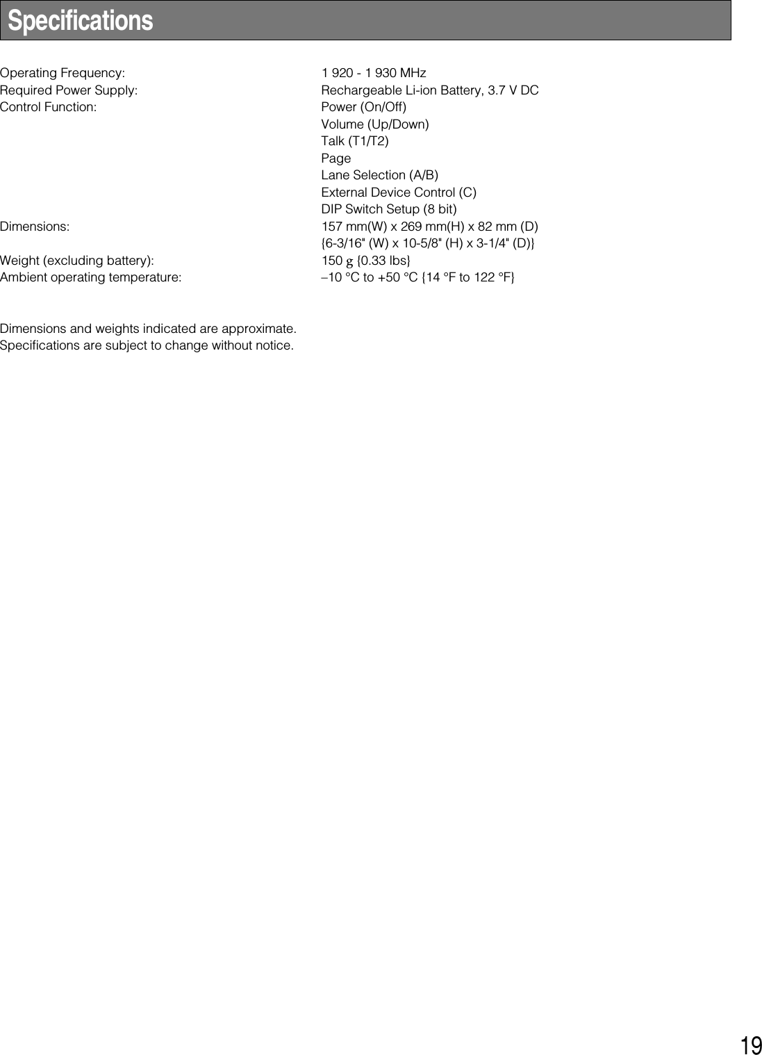
![11■Communications withCustomers [TALK]Any store personnel wearing the headset can communicatebidirectionally with any customer who is at the menu board.1. Select a proper sound level by pressing the !or @ but-ton.2. You will hear a beep in the headset when a vehiclearrives at the menu board.<When the Press-To-Talk (PTT) mode is pre-set>1. Hold down the T1 button and speak to the customer.A short beep is heard in the headset.2. Release the button. Your voice is not heard by the cus-tomer.<When the Talk-Lock mode is preset>1. Press the T1 button and speak to the customer.A short beep is heard in the headset.2. Press the button again. The lock is released, and yourvoice is not be heard by the customer.■Communications with OtherStore Personnel [PAGE]Store personnel wearing the headset can communicate witheach other without being heard by customers.<When the Press-To-Page (PTP) mode is pre-set>1. Hold down the P button and speak into the microphoneat a normal level. 2. Release the button. Your voice will not be heard by theother store personnel.<When the Page-Lock mode is preset>1. Press the P button and speak into the microphone at anormal level. 2. Press the P button again. The lock will be released, andyour voice will not be heard by the other store person-nel.Note: A maximum of 4 operators can have a conversation atthe same time. PressHold downReleasePressPress againHold downReleasePress again](https://usermanual.wiki/Panasonic-of-North-America/9TAWX-H3050/User-Guide-1007627-Page-11.png)
![■Control of the device control ter-minalsThe device control terminals of the center module can becontrolled through the headset. 1. Hold down the C button. A short beep is heard from thespeaker of the headset and a connection will be madetoward the device control terminals of the center mod-ule. 2. Release the C button. A short beep is heard twice fromthe speaker of the headset and the connection will bedisconnected toward the device control terminals of thecenter module. ■Double-Drive-Thru connectionsWhen Double-Drive-Thru connections are made with thecenter module, any headset is required to select the centermodule of either Lane A or Lane B. <For Normal setup>1. When a connection is made to Lane A, the lane indicatoris lit in yellow. Press the T2 button if you want to make aconnection changeover to Lane B. When connected toLane B, a voice of [Lane B] is heard from the speaker ofthe headset and the lane indicator is lit in green. 2. While a connection is maintained to Lane B, the laneindicator is lit in green. Press the T2 button if you want tomake a connection changeover to Lane A. When con-nected to Lane A, a voice of [Lane A] is heard from thespeaker of the headset and the lane indicator is lit in yel-low. <For Direct Lane Select setup>1. While a connection is maintained to Lane A, the laneindicator is lit in yellow. Press the T2 button if you wantto make a connection changeover to Lane B. When con-nected to Lane B, a voice of [Lane B] is heard from thespeaker of the headset and the lane indicator is lit ingreen. 2. While a connection is maintained to Lane B, the laneindicator is lit in green. Press the T1 button if you want tomake a connection changeover to Lane A. When con-nected to Lane A, a voice of [Lane A] is heard from thespeaker of the headset and the lane indicator is lit in yel-low. When Direct Lane Select is set, TALK is available byselecting either lane pressing T1 or T2 button.12PressHold downPressPressPressRelease](https://usermanual.wiki/Panasonic-of-North-America/9TAWX-H3050/User-Guide-1007627-Page-12.png)
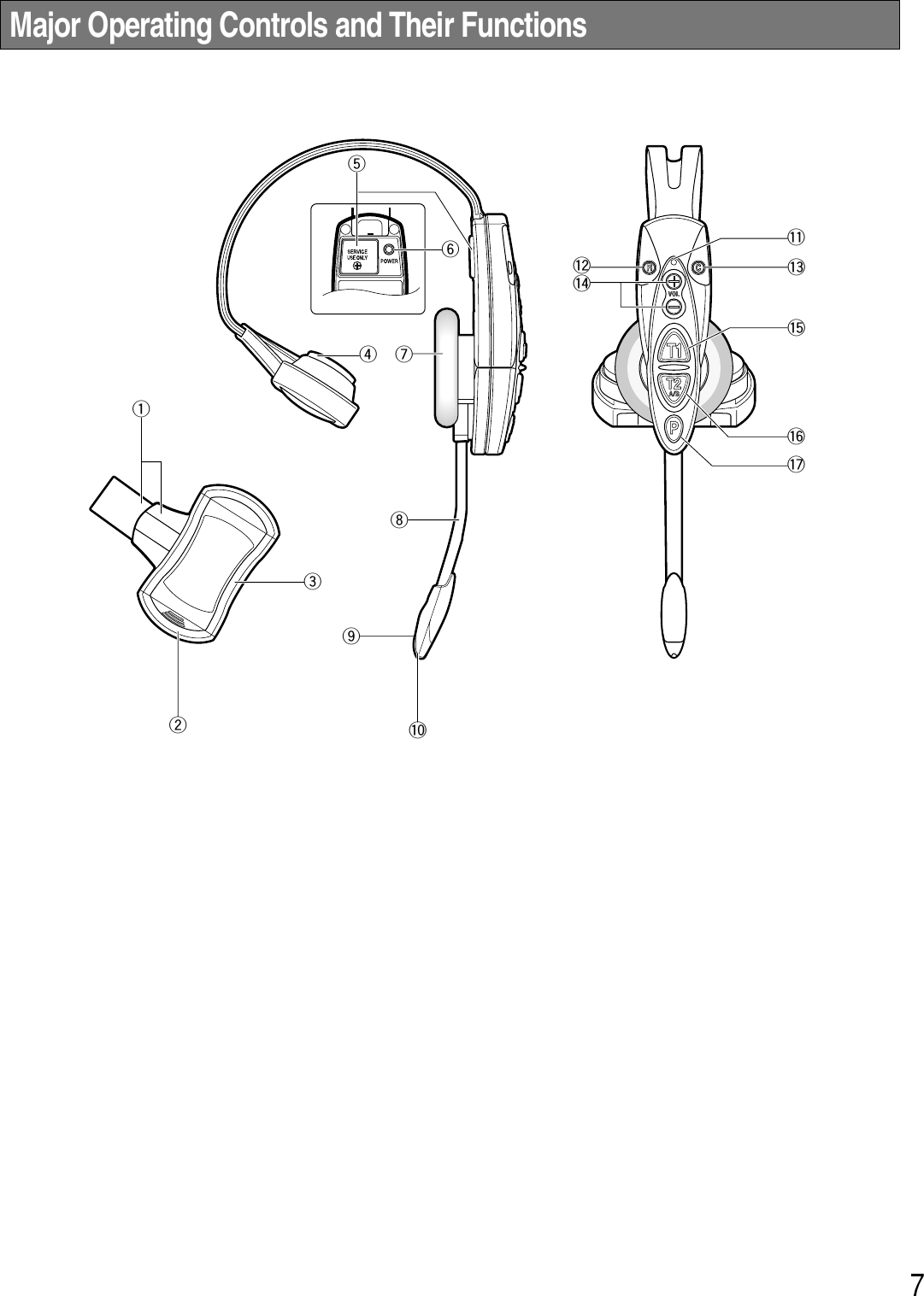
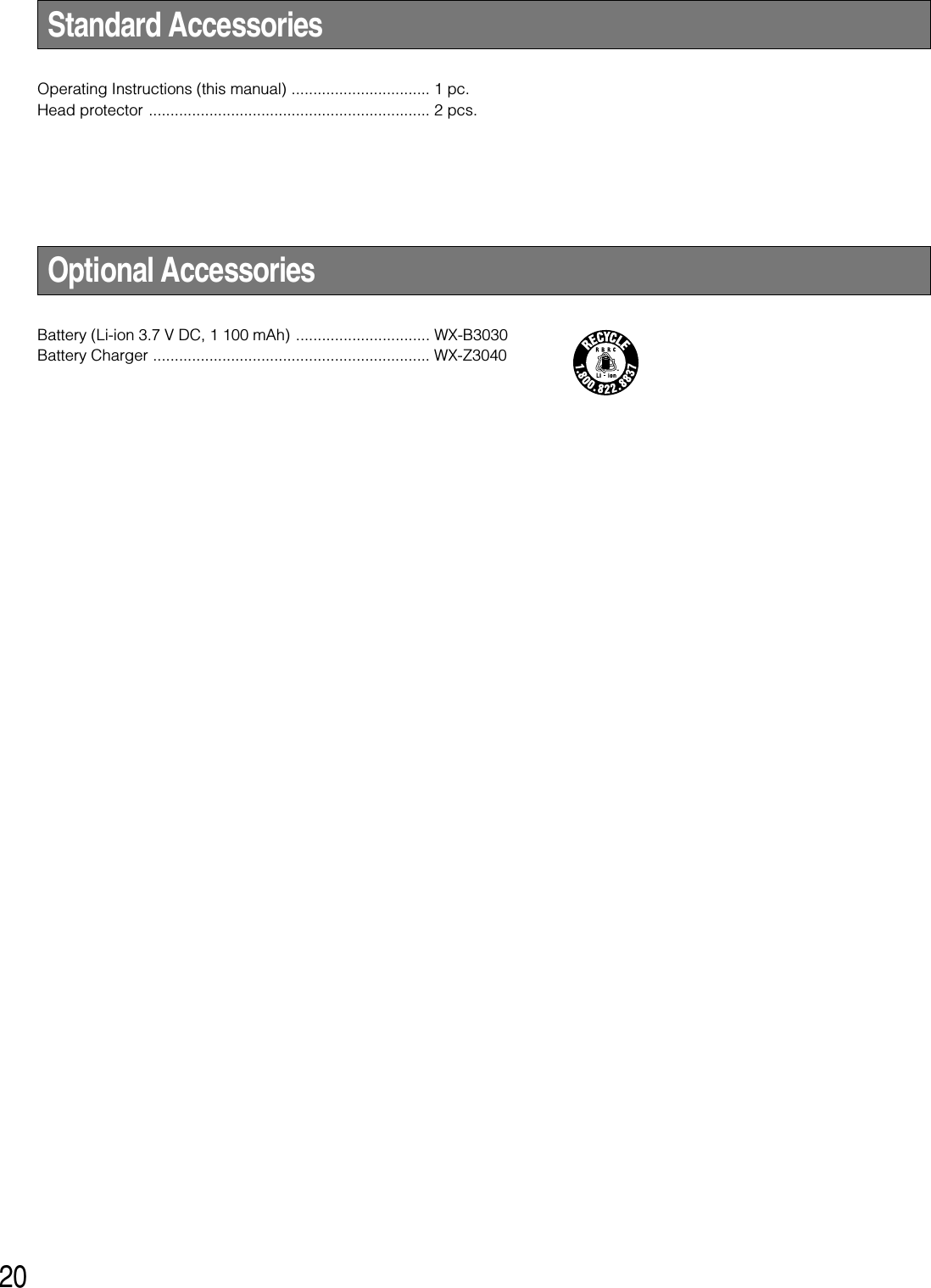
![14■Auto-Talk-Lock setup (for onlyone headset)For a headset where Auto-Talk-Lock is set up, it has a func-tion to select [Talk] automatically when the vehicle detectorhas become active, and you can talk with the customer atthe menu board. 1. Confirm that the DIP Switch 1 of the headset is ON, theDIP Switch 2 is set at the objective lane, and the powerof the headset is OFF. 2. Turn on the headset. The message "Hello Headset **" (**is the number of headset) is output from the speaker ofthe headset, and the power indicator blinks green andred alternately for 3 seconds. While the indicator is blink-ing, press the T1 or T2 button. (LANE A: T1 button,LANE B: T2 button)Auto-Talk-Lock will be set up, The message "Auto-Talk-Lock ON" is heard from the speaker of the headset.When the T1 or T2 button is not pressed, the headsetassumes an ordinary operation mode. 3. In the case of a failure in Auto-Talk-Lock setup, a voiceof [Failed] is heard from the speaker of the headset. Inthis case, the same procedures should be followed fromStep 1 again. Note: If the power of the headset is turned OFF, all the set-ting conditions for Auto-Talk-Lock will be canceled. Thissetting should be carried out without fail when the powersupply is started up.Power button](https://usermanual.wiki/Panasonic-of-North-America/9TAWX-H3050/User-Guide-1007627-Page-14.png)

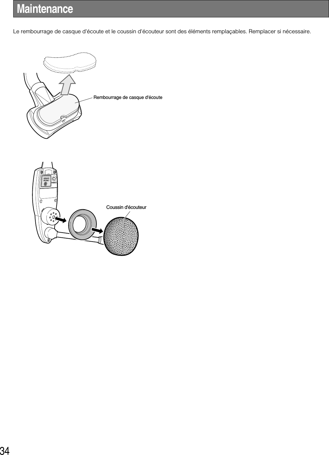
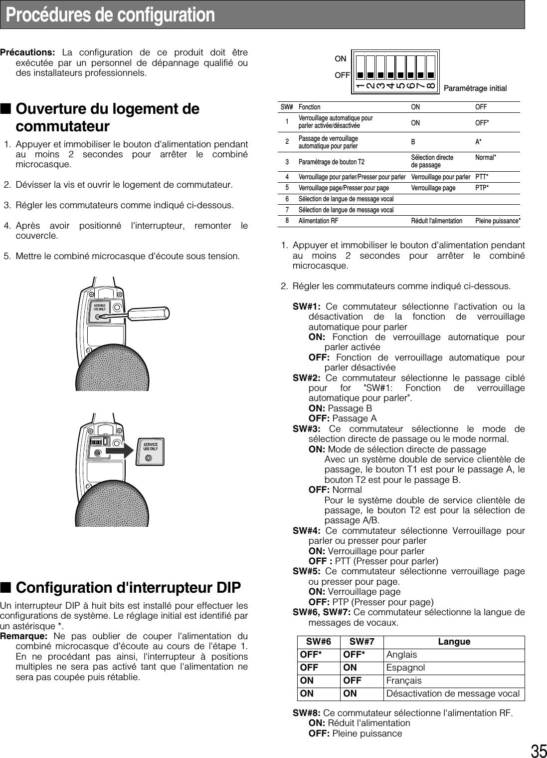
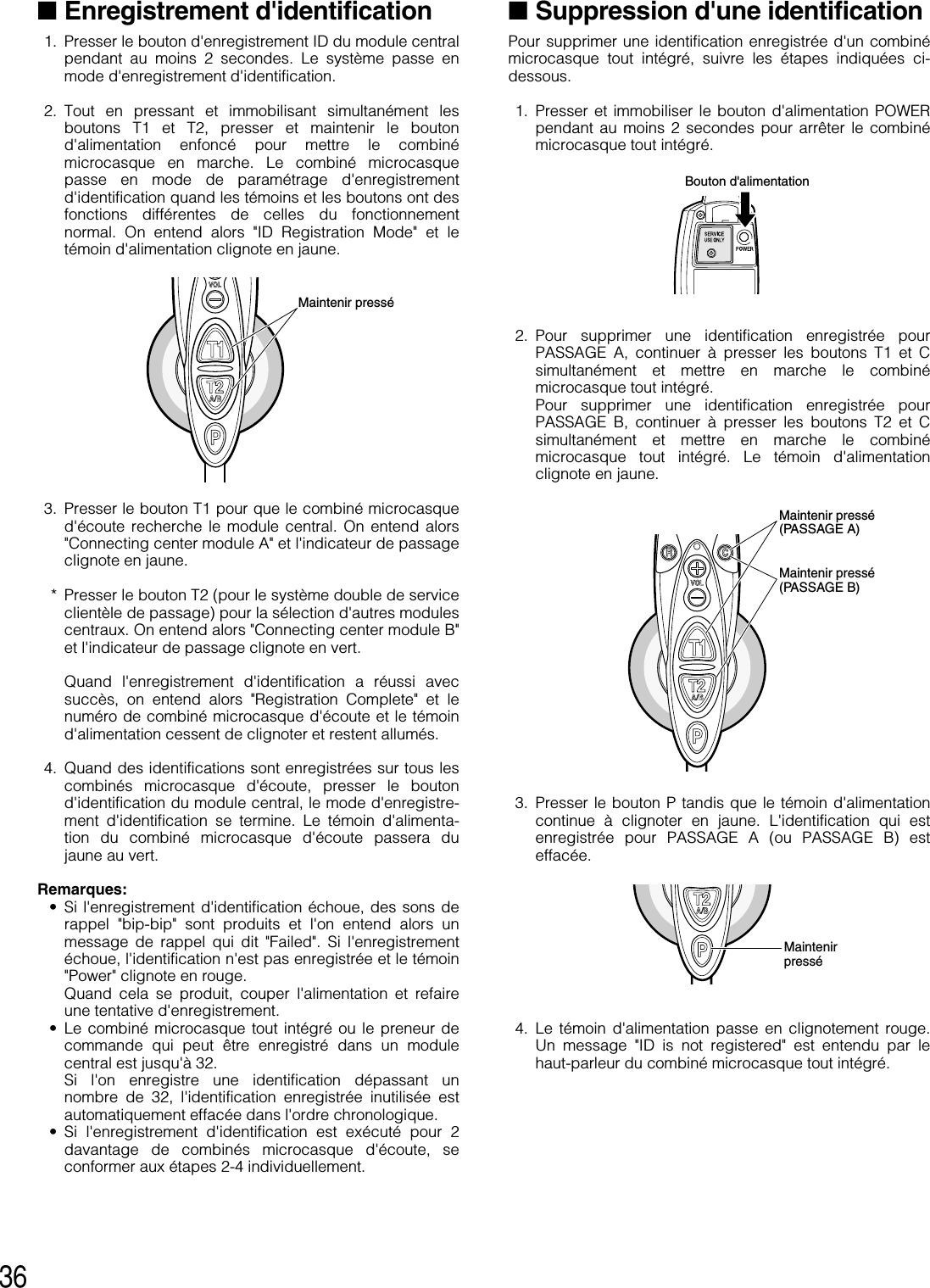
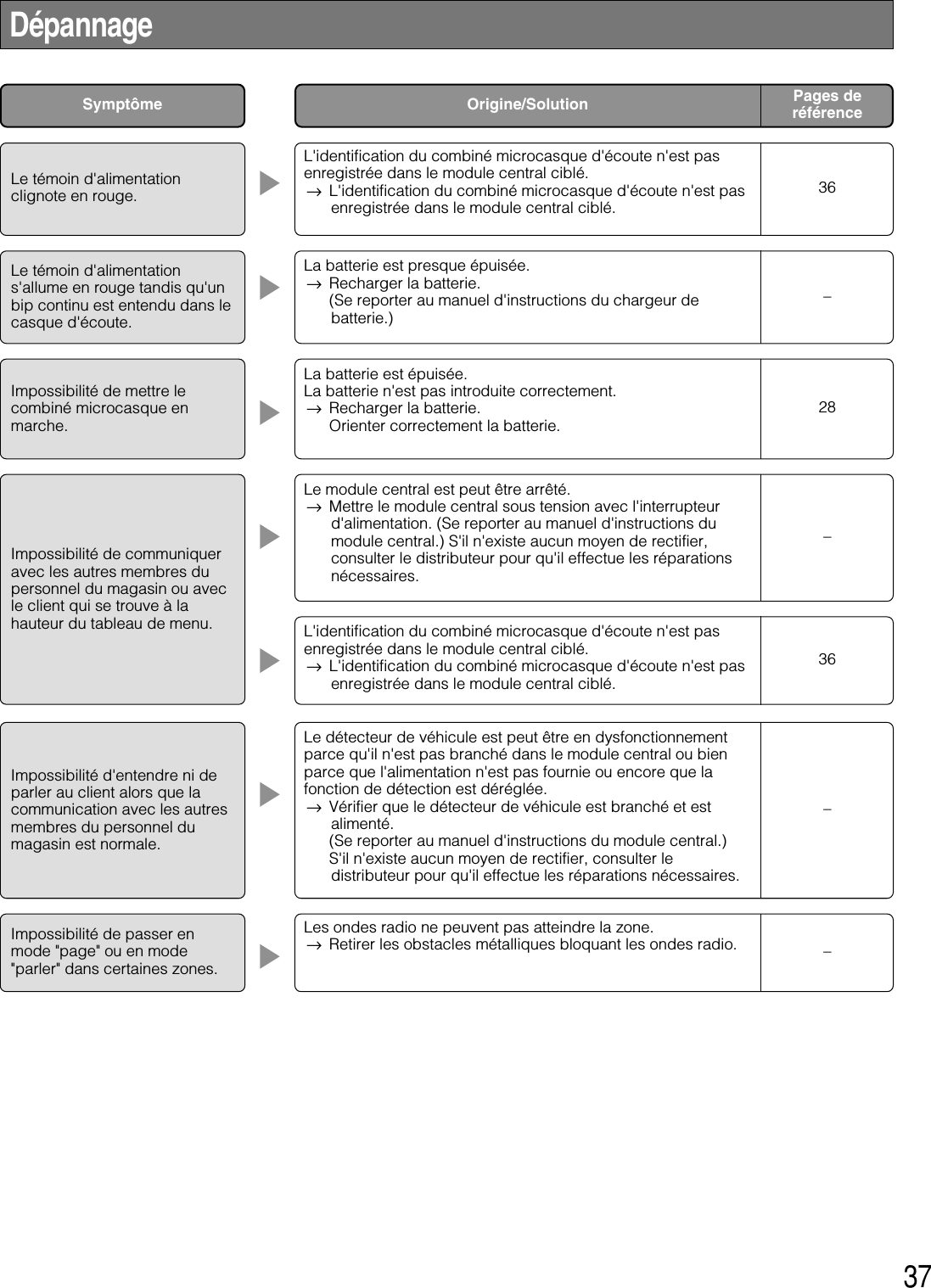
![24Limitation de responsabilité ....................................................................................................................... 22Déni de la garantie ..................................................................................................................................... 22Instructions de sécurité importantes .......................................................................................................... 23Préface ....................................................................................................................................................... 25Caractéristiques dominantes ..................................................................................................................... 25Mesures de précaution .............................................................................................................................. 25Principaux organes de commande et fonctions ......................................................................................... 26Chargement et remplacement de la batterie ............................................................................................. 28■Installation ............................................................................................................................................ 28■Chargement .......................................................................................................................................... 28■Remplacement ..................................................................................................................................... 28Modes d'utilisation ...................................................................................................................................... 29■Préparatifs ............................................................................................................................................ 29■Communications avec les clients [TALK] ............................................................................................. 30■Communication avec d'autres membres du personnel du magasin [PAGE] ...................................... 30■Bornes de commande de périphérique extérieur ................................................................................ 31■Connexion de système double de service clientèle de passage (Double-Drive-Thru) ....................... 31■Mode de gérant (seulement un combiné microcasque d'écoute) ....................................................... 32■Annulation du mode gérant .................................................................................................................. 32■Configuration de la fonction de verrouillage automatique pour parler (pour seulement un combiné microcasque d'écoute) (Auto-Talk-Lock) .............................................. 33Maintenance ............................................................................................................................................... 34Procédures de configuration ...................................................................................................................... 35■Ouverture du logement de commutateur ............................................................................................. 35■Configuration d'interrupteur DIP ........................................................................................................... 35■Enregistrement d'identification ............................................................................................................. 36■Suppression d'une identification .......................................................................................................... 36Dépannage.................................................................................................................................................. 37Caractéristiques techniques ...................................................................................................................... 38Accessoires standard ................................................................................................................................ 38Accessoires optionnels .............................................................................................................................. 39TABLE DES MATIÈRES](https://usermanual.wiki/Panasonic-of-North-America/9TAWX-H3050/User-Guide-1007627-Page-24.png)
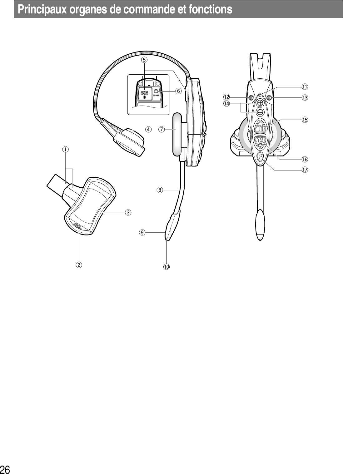
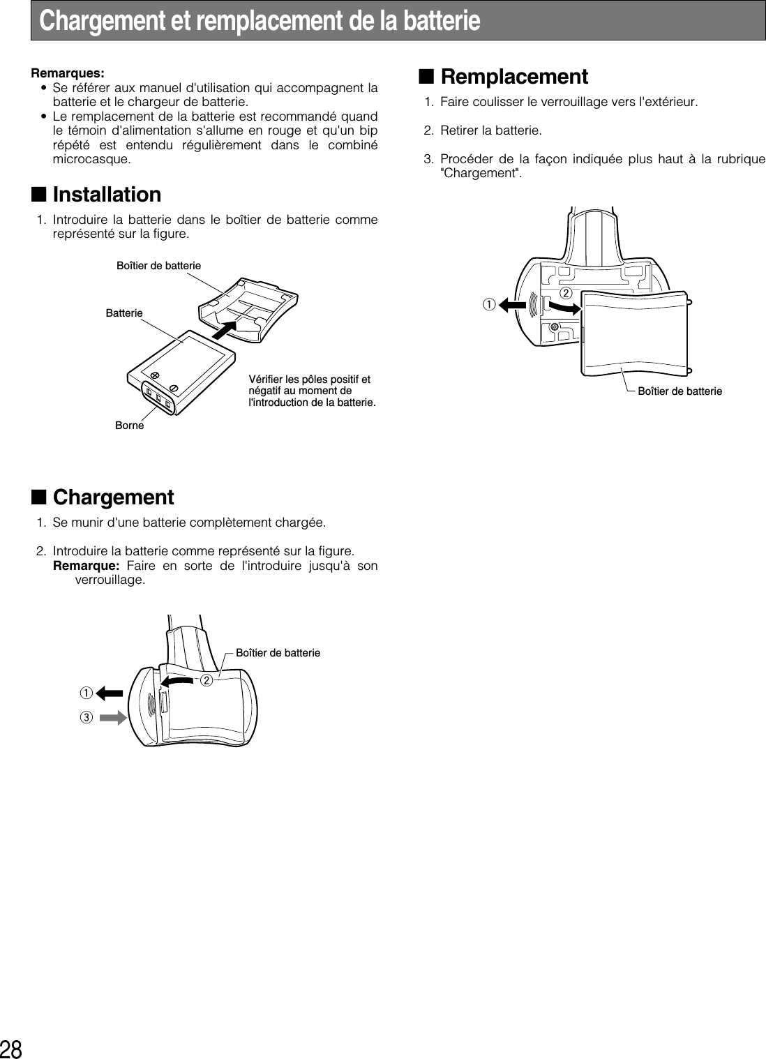
![27qBande de casque d'écoute et rembourrage de casqueS'ajuste à la taille de la tête par coulissement durembourrage de casque.wVerrouillage de batterie [EJECT]Faire coulisser le verrouillage pour retirer la batterie.Lors du chargement d'une batterie, introduire la batteriejusqu'à ce que le verrouillage émette un déclic.eBoîtier de batterie / Batterie (accessoire optionnel)Se référer à la page 25 à "Mesures de précaution".rRembourrage de casque d'écoutetLogement d'interrupteurNe pas ouvrir le couvercle de ce logement. Ne doit êtreouvert que par un technicien professionnel ou desinstallateurs de système qualifiés.yBouton d'alimentation [POWER]Le fait d'appuyer sur le bouton met le combinémicrocasque en marche.Une autre pression du bouton pendant au moins 2secondes permet d'arrêter le combiné microcasqued'écoute.uRembourrage d'écouteuriPerche de microphoneAjuster la position du microphone par rapport à labouche en faisant tourner et en pliant la perche.oMicrophone!0 Indicateur de passageIl s'allume en jaune ou en vert pour indiquer quel est lepassage en service.Jaune: Le passage A est sélectionné.Vert: Le passage B est sélectionné.Jaune clignotant: Le passage A est sélectionné et soitle mode parler soit le mode page est activé.Clignote en vert: Le passage B est sélectionné et soitle mode parler soit le mode page est activé.!1 Indicateur d'alimentationL'indicateur montre l'état actuel comme suit.Vert: L'alimentation est appliquée et l'appareil est enfonction.Clignote en vert: L'alimentation est appliquée et lemode de gérant est activé.Rouge: La batterie doit être rechargée.Rouge clignotant: L'identification n'est pas enregistréeou le module central est réglé en moded'enregistrement d'identification.!2 Touche de téléphone [R]N'est pas utilisé.!3 Bouton de commande de périphérique externe [C]Appuyer et maintenir le bouton C enfoncé pour mettreen marche le périphérique externe.!4 Boutons de réglage de volume [VOL !@]Une pression des boutons a pour effet d'augmenter oude diminuer le niveau de sortie son.!5 Bouton Parler 1 [T1]Ce bouton contrôle les communications avec le client.Lorsque le bouton est relâché, tout ce que dit le clientau tableau de menu est entendu.Alors que le bouton est maintenu pressé en modepresser pour parler, il est possible de parler au client.Alors que le bouton est maintenu pressé en mode deverrouillage pour parler, il est possible de parler auclient jusqu'à ce que le bouton soit pressé une secondefois.!6 Bouton de sélection Parler 2 / Passage A/B [T2, A/B]Ce bouton peut être réglé sur deux fonctions suivant leréglage de l'interrupteur à positions multiples. (Seréférer à p.35 à "Configuration d'interrupteur DIP".)[T2]Ce bouton contrôle les communications avec le clientsur le passage B d'un système double de serviceclientèle de passage.Lorsque le bouton est relâché, tout ce que dit le clientau tableau de menu est entendu.Alors que le bouton est maintenu pressé en modepresser pour parler, il est possible de parler au client setrouvant à la hauteur du tableau de menu.Alors que le bouton est maintenu pressé en mode deverrouillage pour parler, il est possible de parler auclient jusqu'à ce que le bouton soit pressé une secondefois.[A/B]Ce bouton commute entre le passage A et le passage Bet vice versa. L'indicateur de passage !0 affiche lepassage actuellement sélectionné en rouge (A) ou vert(B).!7 Bouton Page [P]Ce bouton contrôle les communications avec lepersonnel du magasin.Lorsque le bouton est relâché, les communications entreles membres du personnel du magasin peuvent êtreentendues.Alors que le bouton est maintenu pressé en modePresser pour parler, il est possible de parler aupersonnel du magasin.Alors que le bouton est maintenu pressé en mode deverrouillage page, il est possible de parler au personneldu magasin jusqu'à ce que le bouton soit pressé uneseconde fois.](https://usermanual.wiki/Panasonic-of-North-America/9TAWX-H3050/User-Guide-1007627-Page-27.png)
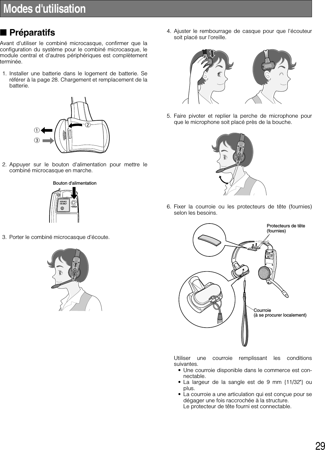
![30■Communications avec lesclients [TALK]Tout membre du personnel portant un combinémicrocasque peut communiquer en mode bidirectionnelavec n'importe quel client qui se trouve à la hauteur dutableau de menu.1. Sélectionner un niveau sonore approprié en appuyantsur le bouton !ou @.2. Une tonalité est entendue dans le combiné microcasquequand un véhicule arrive à la hauteur du tableau demenu.<Lorsque le mode presser pour parler (PTT)est préréglé>1. Presser et immobiliser le bouton T1 et parler au client.Un bip très court se manifeste dans le combinémicrocasque.2. Libérer le bouton. Votre voix ne sera pas perceptible parle client.<Lorsque le mode de verrouillage pour parlerest préréglé>1. Presser le bouton T1 et parler au client.Un bip très court se manifeste dans le combinémicrocasque.2. Presser le bouton encore une fois. Le verrouillage seralibéré et votre voix ne sera plus perceptible par le client.■Communication avec d'autresmembres du personnel dumagasin [PAGE]Tous les membres du personnel portant un combinémicrocasque peuvent communiquer entre eux sans être desclients.<Lorsque le mode presser pour page (PTP) estpréréglé>1. Presser et immobiliser le bouton P et parler dans lemicrophone avec un réglage de niveau normal. 2. Libérer le bouton. Votre voix ne sera pas perceptible parles autres personnes du personnel du magasin.<Lorsque le mode de verrouillage page estpréréglé>1. Presser le bouton P et parler dans le microphone avecun réglage de niveau normal. 2. Presser le bouton P encore une fois. Le verrouillage seralibéré et votre voix ne sera pas perceptible par lesautres personnes du personnel du magasin.Remarque: Un nombre maximum de quatre opérateurspeuvent tenir une conversation en même temps. PresserPresser etimmobiliserLibérer PresserPresser encoreune foisPresser etimmobiliserLibérerPresser encoreune fois](https://usermanual.wiki/Panasonic-of-North-America/9TAWX-H3050/User-Guide-1007627-Page-30.png)
![31■Bornes de commande depériphérique extérieurLes bornes de commande de périphérique du modulecentral peuvent être contrôlées par l'intermédiaire ducombiné microcasque d'écoute. 1. Immobiliser le bouton C en position basse. Un bip courtest entendu par le haut-parleur du combinémicrocasque d'écoute et une connexion sera établie àdestination des bornes de commande de périphériquedu module central. 2. Libérer le bouton C. Un bip court est entendu deux foispar le haut-parleur du combiné microcasque d'écoute etla connexion sera coupée vers les bornes decommande de périphérique du module central. ■Connexion de système doublede service clientèle de passage(Double-Drive-Thru)Quand les connexions de système double de serviceclientèle de passage sont établies avec le module central,n'importe quel combiné microcasque d'écoute est obligé desélectionner le module central du passage A ou du passageB. <Pour une configuration normale>1. Quand une connexion est établie au passage A,l'indicateur de passage s'allume en jaune. Presser lebouton T2 si l'on souhaite faire un changement deconnexion vers le passage B. Une fois connecté aupassage B, une voix [Lane B] est entendue par le haut-parleur du combiné microcasque d'écoute et l'indicateurde passage s'allume en vert. 2. Quand une connexion est maintenue sur le passage B,l'indicateur de passage s'allume en vert. Presser lebouton T2 si l'on souhaite faire un changement deconnexion vers le passage A. Une fois connecté aupassage A, une voix [Lane A] est entendue par le haut-parleur du combiné microcasque d'écoute et l'indicateurde passage s'allume en jaune. <Pour une configuration de système double deservice clientèle de passage>1. Quand une connexion est maintenue sur le passage A,l'indicateur de passage s'allume en jaune. Presser lebouton T2 si l'on souhaite faire un changement deconnexion vers le passage B. Une fois connecté aupassage B, une voix [Lane B] est entendue par le haut-parleur du combiné microcasque d'écoute et l'indicateurde passage s'allume en vert. 2. Quand une connexion est maintenue sur le passage B,l'indicateur de passage s'allume en vert. Presser lebouton T1 si l'on souhaite faire un changement deconnexion vers le passage A. Une fois connecté aupassage A, une voix [Lane A] est entendue par le haut-parleur du combiné microcasque d'écoute et l'indicateurde passage s'allume en jaune. Quand Sélection de passage direct est réglée, TALK estdisponible en sélectionnant l'un ou l'autre passage enappuyant sur le bouton T1 ou le bouton T2.Presser etimmobiliserPresserPresserPresserLibérerPresser](https://usermanual.wiki/Panasonic-of-North-America/9TAWX-H3050/User-Guide-1007627-Page-31.png)
![33■Configuration de la fonction deverrouillage automatique pourparler (pour seulement uncombiné microcasque d'écoute)(Auto-Talk-Lock)Pour un combiné microcasque d'écoute où la fonction deverrouillage automatique pour parler est configurée, il a unefonction pour sélectionner [Parler] automatiquement quandle détecteur de véhicule est devenu actif, et si l'on parleavec le client au tableau de menu. 1. Confirmer que l'interrupteur à positions multiples 1 ducombiné microcasque d'écoute est en fonction, quel'interrupteur à positions multiples 2 est réglé sur lepassage objectif et que l'alimentation du combinémicrocasque d'écoute est coupée. 2. Mettre le combiné microcasque d'écoute sous tension.Le message "Hello Headset **" (** correspond aunuméro du combiné microcasque d'écoute) est émispar le haut-parleur du combiné microcasque d'écoute etle témoin d'alimentation clignote en vert et en rougealternativement pendant 3 secondes. Tandis que letémoin d'alimentation clignote, presser le bouton T1 ouT2. (PASSAGE A: Bouton T1, PASSAGE B: Bouton T2)La fonction de verrouillage automatique pour parler seraparamétrée, le message "Auto-Talk-Lock ON" estentendu par le haut-parleur du combiné microcasqued'écoute. Quand le bouton T1 ou T2 n'est pas pressé, lecombiné microcasque d'écoute assume un modeordinaire de fonctionnement. 3. Dans le cas d'une défaillance de la configuration de lafonction de verrouillage automatique pour parler, unevoix [Failed] est entendue par le haut-parleur ducombiné microcasque d'écoute. Dans ce cas de figure,se conformer à nouveau aux instructions des mêmesprocédures indiquées à l'étape 1. Remarque: Si le courant d'alimentation du combinémicrocasque d'écoute est coupé, toutes les conditionsde réglage pour la fonction de verrouillage automatiquepour parler seront annulées. Ce réglage devrait êtreeffectué sans faute quand l'alimentation électrique estappliquée.Bouton d'alimentation](https://usermanual.wiki/Panasonic-of-North-America/9TAWX-H3050/User-Guide-1007627-Page-33.png)