Panasonic Mva Series Air Handling Unit Service Manual IOM 1.0
2015-05-18
: Panasonic Panasonic-Mva-Series-Air-Handling-Unit-Service-Manual-730493 panasonic-mva-series-air-handling-unit-service-manual-730493 panasonic pdf
Open the PDF directly: View PDF ![]() .
.
Page Count: 38
035-000039-001 Page 1 of 38 MVA IOM 1.0 4-25-2014
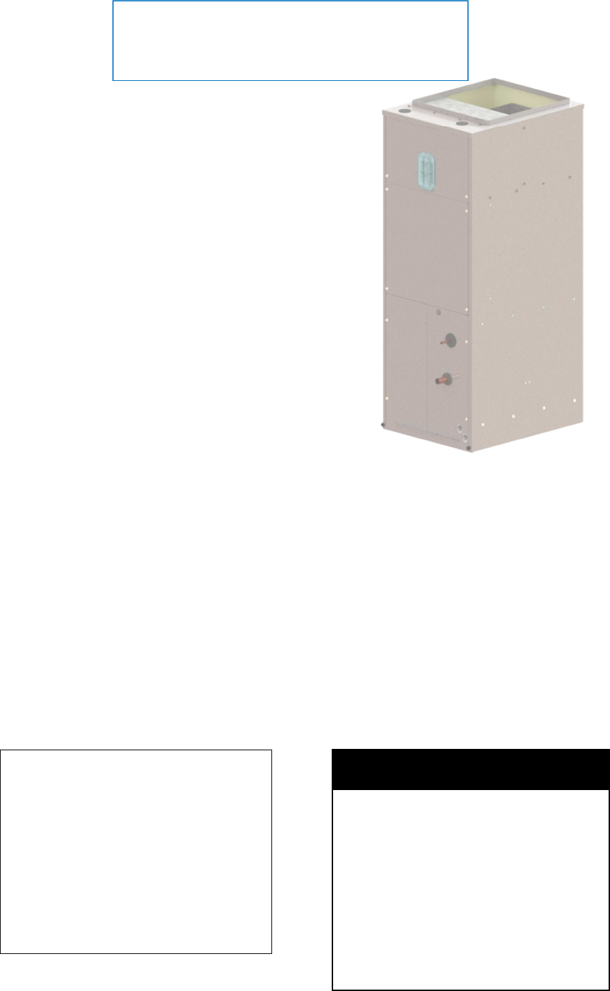
MVA Series units are direct drive vertical
and multi-position Air Handlers delivering
nominal cooling capacities of 1.5 to 5 tons.
Units may be specified with hot water or elec-
tric heating coils to meet space cooling loads
or heating loads or both. Three return air con-
figurations are available for maximum flexibil-
ity.
How to Use this Manual:
This manual gives instructions regarding in-
stallation, operation and maintenance for the
MVA Series air handling units.
Use these instructions in conjunction with
other appropriate instructions, including but
not limited to those instructions supplied with
the outdoor unit. Installation must comply
with all applicable local codes.
GENERAL
Installation and maintenance are to be per-
formed only by qualified personnel who are fa-
miliar with local codes and regulations and are
experienced with HVAC equipment of this type.
WARNING: Sharp edges, coil surfaces
and rotating fans are a potential injury
hazard – avoid contact.
WARNING: Hazardous voltage – Discon-
nect and Lock Out all incoming power
sources before servicing or installing unit.
ELECTRIC SHOCK CAN CAUSE DEATH.
WARNING: This equipment may be in-
stalled well above finished floor—Use ex-
treme caution when working at heights.
SAFETY WARNING:
Installer should pay particular attention to
the following words:
NOTE–intended to clarify or make instal-
lation easier.
CAUTION–given to prevent equipment
damage.
WARNING–to alert installer that personal
injury and/or equipment damage may
result if installation procedure is not
properly followed.
UNPACKING-CHECK FOR DAMAGE!
Immediately inspect each unit for dam-
age upon receipt.
Inspect units for external and concealed
damage immediately.
File any damage claims in accordance
with the Freight Damage Policy and
Terms and Conditions.
Do not repair damaged units without
written authorization.
Protect stored units from damage.
MVA Series Air Handling Unit
Installation, Operation and Maintenance
Manual
035-000039-001 Page 2 of 38 MVA IOM 1.0 4-25-2014
THIS PAGE INTENTIONALLY LEFT BLANK

035-000039-001 Page 3 of 38 MVA IOM 1.0 4-25-2014
/ŶƐƚĂůůĂƟŽŶ͕ ^ƚĂƌƚ-Up
and Service
/ŶƐƚƌƵĐƟŽŶƐ
MVA Series Air Handling Unit
Installation, Operation and Maintenance
Manual
Topic Page
SAFETY CONSIDERATIONS 1, 5
PRODUCT NOMENCLATURE 6-7
UNPACKING 8
INSTALLATION 8
Pre-installation 8
Rigging 8
Unpackaging 8
Service Clearances 8,11,12
Return Air & Unit Orientation 9
Vertical to Horizontal Conversion (EEV) 10
Unit Suspension or Floor Mount 8,13,14
Condensate Drain 13
Ductwork 13
Refrigerant Piping 15
Electric Heater Accessory 15-16
Electrical 17-23
START-UP 24-26
Fan Airflow Step-Up 24-25
Airflow Data 25-26
SERVICE 27-29
Fan & Fan Motor 27-28
Filters 29
Access Panels 29
Coil & Drain Pan Service 30
ELECTRICAL RATINGS 31
DIMENSIONS 32-35
Startup Report 37
035-000039-001 Page 4 of 38 MVA IOM 1.0 4-25-2014
THIS PAGE INTENTIONALLY LEFT BLANK
035-000039-001 Page 5 of 38 MVA IOM 1.0 4-25-2014
WARNING
CHECK the assembly and component weights to
be sure that the rigging equipment can handle
them safely.
Note also, the centers of gravity and any specific
rigging instructions.
CHECK for adequate ventilation so that fumes will
not migrate through ductwork to occupied spaces
when welding or cutting inside air-handling unit
cabinet or plenum.
WHEN STEAM CLEANING COILS be sure that
the area is clear of personnel.
DO NOT attempt to handle access covers and re-
movable panels on outdoor units when winds are
strong or gusting until you have sufficient help to
control them. Make sure panels are properly se-
cured while repairs are being made to a unit.
DO NOT remove access panel fasteners or open
access doors until fan is completely stopped. Pres-
sure developed by a moving fan can cause exces-
sive force against the panel which can injure per-
sonnel.
DO NOT work on dampers until their operators are
disconnected.
BE SURE that fans are properly grounded before
working on them.
Failure to follow these warnings could result in per-
sonal injury or equipment damage.
DANGER
NEVER enter an enclosed fan cabinet or reach into
a unit while the fan is running.
LOCK OPEN AND TAG the fan motor power dis-
connect switch before working on a fan. Take fuses
with you and note removal on tag. Electric shock
can cause personal injury or death.
LOCK OPEN AND TAG the electric heat coil power
disconnect switch before working on or near heat-
ers.
Failure to follow these warnings could lead to per-
sonal injury or death.
035-000039-001 Page 6 of 38 MVA IOM 1.0 4-25-2014
PRODUCT NOMENCLATURE
Unit Type/Size
Code Selection
01, 02 MV
Generation/Series
Code Selection
03 A
Unit Type/Size
Code Selection NOM Capacity
18
24
30 30,000 Btu/hr
36
42
48
60
Primary Coil Type
Code Selection
06 F4 ROW DX with electronic expansion valve, R-410a
Heating Coil
Code Selection
B
C
D
E
F
G
H
I19.5 kW - single phase w/circuit breaker only * 1 stage (size 42, 48, 60)
Notes: *
Future Use Description
Code Selection
08 A
1. Electric Heat KW rated at 230V. For 208V operation, derate heater to 75% of 230V rating.
2. Electric Heat complete with circuit breaker style power switch.
3. 14.5 and 19.5 kW shall have two supply circuits.
Future Use
Description
Description
Description
07
Electric Heat Ready (field installed kit - EH Top will be provided)*
3.0 kW - single phase w/circuit breaker only *1 stage (all sizes)
5.0 kW - single phase w/circuit breaker only * 1 stage (all sizes)
6.0 kW - single phase w/circuit breaker only * 1 stage (all sizes)
8.0 kW - single phase w/circuit breaker only * 1 stage (all sizes)
9.5 kW - single phase w/circuit breaker only * 1 stage (all sizes)
14.5 kW - single phase w/circuit breaker only * 1 stage (size 30 to 60)
04, 05
18,000 Btu/hr
24,000 Btu/hr
36,000 Btu/hr
60,000 Btu/hr
42,000 Btu/hr
48,000 Btu/hr
Revision Level
Description
Direct Drive Multiposition air handling unit
Description
035-000039-001 Page 7 of 38 MVA IOM 1.0 4-25-2014
Unit Grade Description
Code Selection
09 S
Unit Voltage
Code Selection
10 6
Controls
Code Selection
11 H
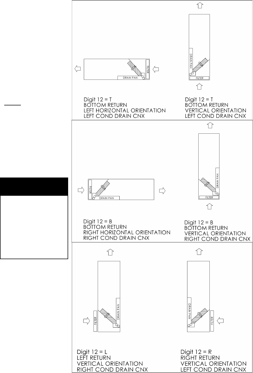
Return Air Cabinet Options
Ordering Number
Code Selection Return Location
BBottom Return
RRight Return
LLeft Return
TBottom Return
Drain Pan
Code Selection
C
D
G
H
Tracking Description
Code Selection
14 P
Vertical (Front RH Cond
Drain Cnx)
Unit Orientation
Horizontal Left or
Vertical (Front LH
Condensate Drain Cnx)
Panasonic
12
Note: Right return, horizontal orientation, or left hand condensate drain connections require
"Universal" drainpan selection. See code 13.
Description
drain pan and cabinet insulation type
13
Fiberglass, Universal Drainpan - Galvanized
Fiberglass, Universal Drainpan - Stainless Steel
Foil Face Fiberglass, Universal Drainpan - Galvanized
Foil Face Fiberglass, Universal Drainpan - Stainless Steel
Vertical (Front RH Cond
Drain Cnx) or Horizontal
Right
Vertical (Front LH Cond
Drain Cnx)
Description
208/230/1/60 ECM-VE (customer change transformer tap for 208V)
Description
Panasonic control board & low voltage interface
Standard
Description
PRODUCT NOMENCLATURE—CONT’D

035-000039-001 Page 8 of 38 MVA IOM 1.0 4-25-2014
Pre-installation
1. Check items received against packing list.
2. Do not stack unit components or accesso-
ries during storage. Stacking can cause
damage or deformation.
3. If unit is to be stored for more than 2 weeks
prior to installation, observe the following
precautions:
a. Choose a dry storage site that is rea-
sonably level and sturdy to prevent un-
due stress or permanent damage to the
unit structure or components. Do not
store unit on vibrating surface. Damage
to stationary bearings can occur. Set
unit off ground if in heavy rain area.
b. Remove all fasteners and other small
parts from jobsite to minimize theft. Tag
and store parts in a safe place until
needed.
c. Cover entire unit with a tarp or plastic
coverall. Extend cover under unit if
stored on ground. Secure cover with
adequate tie-downs or store indoors.
Be sure all coil connections have pro-
tective shipping caps.
d. Monthly — Remove tarp from unit, en-
ter fan section through access door or
through fan inlet, and rotate fan and
motor slowly by hand to redistribute the
bearing grease and to prevent bearing
corrosion.
Rigging — Do not remove shipping skids or
protective covering until unit is ready for final
placement. Use slings and spreader bars as ap-
plicable to lift unit. Do not lift unit by coil connec-
tions or headers.
Do not remove protective caps from coil
piping connections until ready to connect
piping.
WARNING-AUXILIARY DRAIN PAN
RECOMMMENDED:
This product has an auxiliary condensate drain
which should be piped to a condensate overflow
sensor or safe drain location or both to protect
the equipment and property from damage in the
case of condensate overflow.
In addition, the International Mechanical Code
(IMC) section 307.2.3 requires the use of auxil-
iary drain pans. Many municipalities have
adopted this code.
This practice represents the standard for profes-
sional installation whether or not this code has
been adopted in a specific municipality or terri-
tory. As such, water damages that would have
been prevented had an auxiliary pan been de-
ployed will not be considered for compensation.
This position is taken regardless of whether the
source of the moisture was specified as a po-
tential failure mode in the applicable building
code or not. A freeze burst, cracked drain pan,
failed weld, or corrosion induced leak are some
of the potential failure modes that are mitigated
when an auxiliary pan is properly installed. Pro-
fessional installers recognize the value of pro-
tecting customer assets against foreseeable
events. Customers who choose to avoid the
cost of common protective measures waive their
right to seek damages when those foreseeable
events occur. If the product is located above a
living space or where damage may result from
condensate overflow, install a watertight pan of
corrosion-resistant metal beneath the unit to
catch over-flow which may result from clogged
drains or from other reasons. Provide proper
drain piping for this auxiliary pan. Consult local
codes for additional precautions before installa-
tion.
Unpackaging
1. Remove all packaging and any foreign mate-
rial from unit.
2. Check blower wheel for free rotation.
3. Check copper lines, coil etc. for internal or
hidden damage.
Return Air and Unit Orientation
Units may be positioned in several configura-
tions depending on the return air configura-
tion selected—see Figure 1.
NOTE: Right and left return units are not
recommended for horizontal installation.
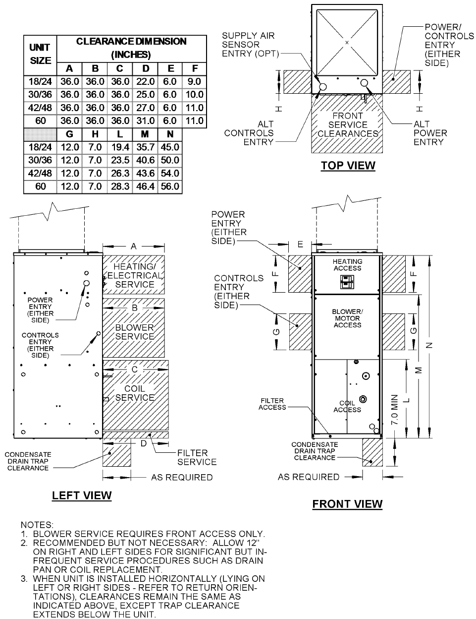
Service Clearance
The fan coil is completely serviceable from
the front. Units are approved for 0” (zero
INSTALLATION
inches) of clearance. This allows substan-
tial freedom in the positioning of the unit to
best serve the requirements of the struc-
ture.
Unit Support
Floor mounting: Unit may be mounted on a
housekeeping pad, floor, platform or plenum.
Provide a suitable isolation pad to minimize
sound transmission to the structure. CAU-
TION! Make sure to allow enough eleva-
tion to permit construction of the conden-
sate trap. Also allow enough elevation
and clearance for opening the filter door
(removes to the front). See Service Clear-
ances.
035-000039-001 Page 9 of 38 MVA IOM 1.0 4-25-2014
INSTALLATION
Figure 1
Return Configurations and
Unit Orientations
NOTE:
Electronic Expansion
Valve (EEV) must be ori-
ented vertically, and is
shipped for vertical cabi-
net orientation.
For horizontal cabinet
orientation, follow proce-
dure to rotate the EEV
assembly. Refer to Fig-
ure 2.
WARNING
FOR HORIZONTAL CABI-
NET ORIENTATION, EEV
MUST BE ROTATED TO
VERTICAL POSITION!
Failure to reorient the
EEV can result in im-
proper unit operation or
equipment damage or
dangerous condition.
035-000039-001 Page 10 of 38 MVA IOM 1.0 4-25-2014
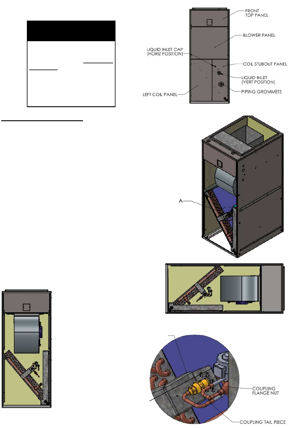
INSTALLATION—VERTICAL TO HORIZON-
TAL CONVERSION—EEV ROTATION
WARNING
FOR HORIZONTAL CABINET
ORIENTATION, EEV MUST
BE ROTATED TO VERTICAL
POSITION! Failure to reori-
ent the EEV in VERTICAL
position can result in improp-
er unit operation or equip-
ment damage or dangerous
condition.
CONVERSION PROCEDURE:
1. UNIT IS SHIPPED WITH NITROGEN
CHARGE. IF UNIT HAS ALREADY BEEN
CHARGED WITH REFRIGERANT, REMOVE RE-
FRIGERANT CHARGE PER LOCAL CODES BE-
FORE PERFORMING CONVERSION PROCE-
DURE.
2. REMOVE PIPING PLUGS AND SAVE FOR LAT-
ER USE. NITROGEN WILL DISCHARGE FROM
COIL.
3. REMOVE PIPING GROMMETS; REMOVE LIQ-
UID INLET CAP FOR HORIZONTAL POSITION.
4. REMOVE BLOWER PANEL, LEFT AND RIGHT
COIL PANELS
5. SECURE EEV BRACKET WITH WRENCH AND
TURN COUPLING FLANGE NUT COUNTER
CLOCKWISE WITH 3/4" WRENCH TO LOOSEN
AND DISCONNECT COUPLING. THE COU-
PLING TAIL NUT SHOULD BE ALLOWED TO
TURN FREELY.
6. REPOSITION EXPANSION VALVE ASSEMBLY
AS SHOWN IN FIGURE 2d. ENSURE EXPAN-
SION VALVE IS VERTICAL WITHIN +/- 15 DEG
WITH UNIT INSTALLED IN HORIZONTAL POSI-
TION 7. REATTACH COUPLING AND
TIGHTEN TO 10-12 FT LBS
WHILE SECURING EEV BRACK-
ET WITH WRENCH.
8. AS AN ALTERNATIVE TO
STEP 5 COUPLING MAY BE
TIGHTENED UNTIL NO
THREADS ARE SHOWING
AND COUPLING IS BOT-
TOMED OUT. THEN TURN
AN ADDITIONAL 60 DEG
(OR ONE HEX FLAT) TO
TIGHTEN.
9. REINSTALL FRONT
PANELS, GROMMETS,
AND PIPING PLUGS.
Figure 2a-
Vertical
Orientation
Figure 2b-
Vertical
Orientation
Figure 2c-Vertical
Orientation, Panels
Removed
Figure 2d-Horizontal
Orientation
Detail A-
EEV Detail
EEV IN VERTICAL
ORIENTATION
EEV BRACKET
035-000039-001 Page 11 of 38 MVA IOM 1.0 4-25-2014
INSTALLATION—SERVICE CLEARANCES
035-000039-001 Page 12 of 38 MVA IOM 1.0 4-25-2014
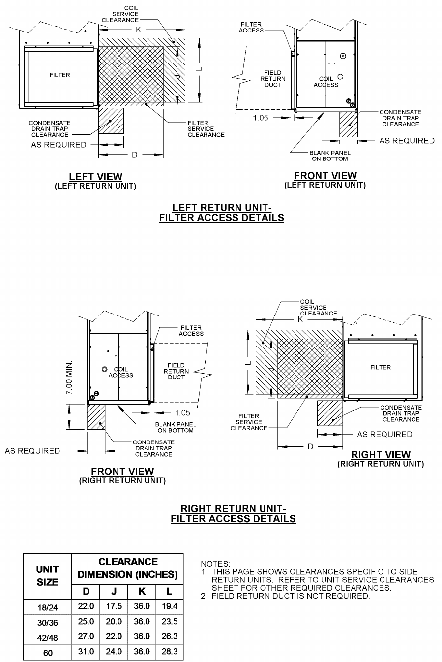
INSTALLATION—SERVICE CLEARANCES-
SIDE RETURN FILTER DETAILS
035-000039-001 Page 13 of 38 MVA IOM 1.0 4-25-2014
Install the unit so that it is level or pitches
slightly –(1/8 inch) – toward the condensate
drain connection.
Anchor the unit to the plenum or platform
through the bottom flange using 2ea #10 sheet
metal screws on each side (4 screws total).
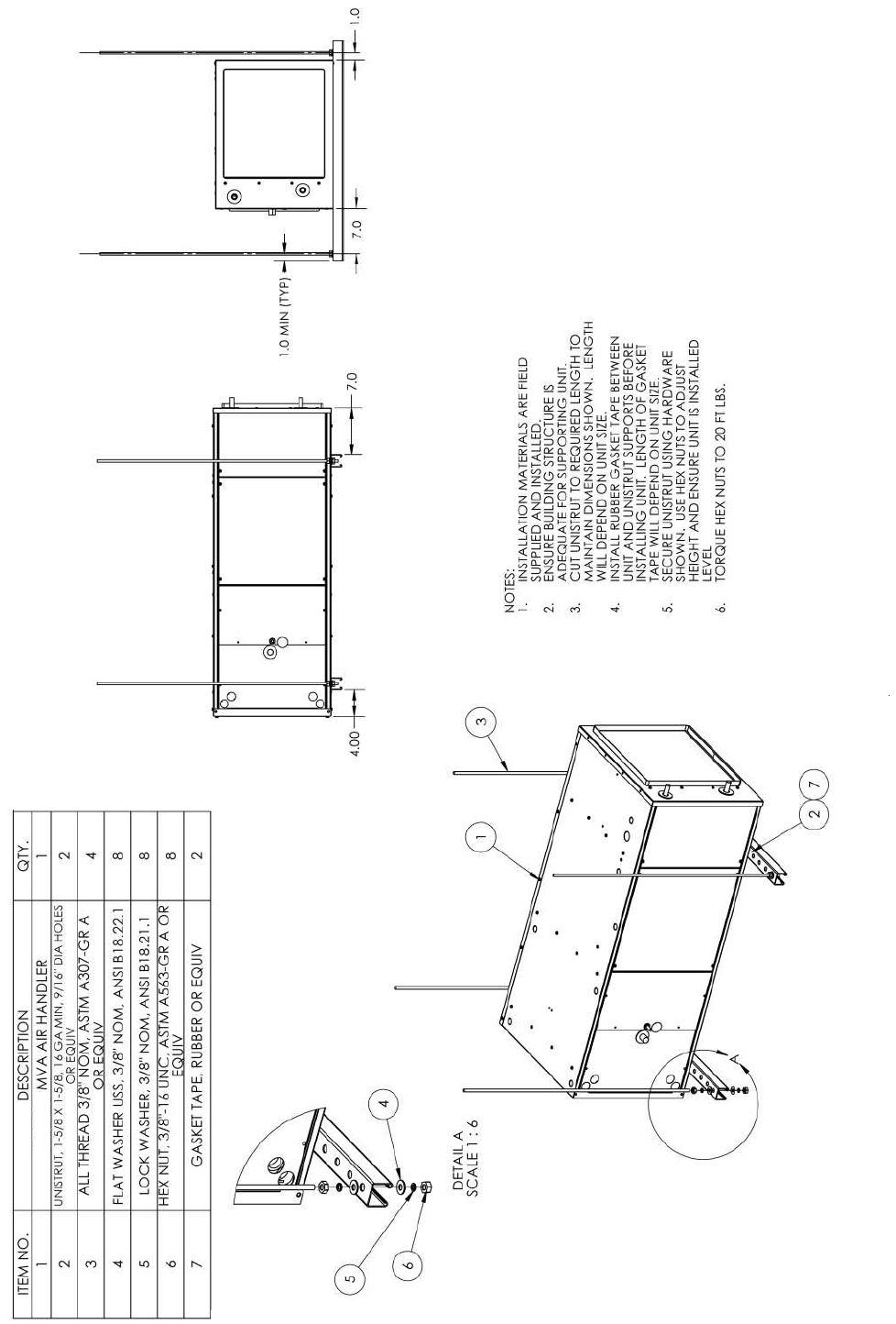
Ceiling Suspension: Mount the unit in ceiling-
suspended horizontal orientation per suspen-
sion details (Figure 4). Unit is NOT intended
to be wall mounted. Consult a qualified struc-
tural engineer for special mounting considera-
tions.
Install the unit so that it pitches slightly –(1/8
inch) – toward the condensate drain connec-
tion.
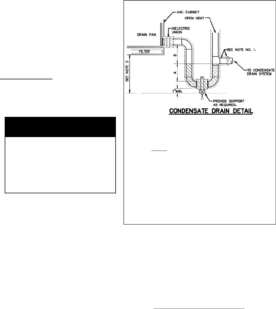
Condensate Drain
Install a trapped condensate drain line at unit drain
connection. All MVA units have 3/4 in. FPT con-
densate main and auxiliary drain connections.
Provide adequate trap clearance (trap depth) be-
neath the unit as indicated in Fig. 3. Provide
freeze-up protection as required to insure reliable
condensate drainage. Freeze protection
measures are customer-supplied and installed.
Pipe to condensate drain using PVC or copper or
other suitable material. Pitch drain piping down-
ward at a minimum slope of 1/8 inch per foot.
Pipe auxiliary drain to “tell tale” drain location or
floor drain to clearly indicate when condensate
drain service is required. Alternately, use a field-
provided condensate overflow detection device in
the auxiliary drain connection to provide alarm or
other controls action when the drain pan fills to the
level of the auxiliary drain.
Placing Unit In Ductwork
1. Utilize flexible transitions on supply and return
connections to reduce noise and vibration trans-
mission to the structure.
INSTALLATION
WARNING
INSURE THAT THE UNIT IS ADE-
QUATELY SUPPORTED FROM
STRUCTURE TO PREVENT DAMAGE
OR INJURY CAUSED BY FALLING
EQUIPMENT! If uncertain about how
to connect to the structure, consult a
qualified structural engineer.
Fig. 3 — Condensate Drain
2. When the connecting return air duct is
smaller than the coil inlet opening, construct
the transition piece so that the vertical and
horizontal dimensions of the transition piece
do not increase more then one inch for eve-
ry seven inches of length of the transition
piece.
2. Provide at least three feet of straight
duct work preceding the unit inlet.
Duct Insulation and Vapor Proofing:
Properly select and install duct insulation as
required by the application.
All externally insulated duct work must have
an adequate vapor seal for summer opera-
tion. This is particularly important where the
duct is exposed to highly humid conditions
in such places as attics, vented crawl spac-
es, unconditioned basements, and utility
rooms. The vapor seal prevents condensa-
tion of moisture in the insulating material
and subsequent loss of its insulating value.
NOT TO SCALE
MAINTAIN THESE DIMENSIONS FOR ADEQUATE TRAP
SEAL:
A = 3.5” MINIMUM
B = 2.0” MINIMUM
NOTES:
1. CONDENSATE DRAIN PIPING RECOMMENDATIONS:
A. MINIMUM 3/4” Φ PIPE SIZE
B. COPPER OR PVC PIPE MATERIAL
C. USE DIELECTRIC UNION FOR DISSIMILAR METALS.
D. INSULATE PER PROJECT SPECIFICATIONS.
2. PAD OR PLENUM HEIGHT AS REQUIRED TO INSTALL
TRAP AND CONDENSATE DRAIN PIPING.
3. AVOID BLOCKING FILTER SERVICE ACCESS WHEN
INSTALLING CONDENSATE DRAIN PIPING.
035-000039-001 Page 14 of 38 MVA IOM 1.0 4-25-2014
Figure 4
CEILING SUSPENSION DETAILS
035-000039-001 Page 15 of 38 MVA IOM 1.0 4-25-2014
INSTALLATION
CAUTION
Direct-expansion coils are shipped pressurized
with dry nitrogen. Release pressure from the coil
through valves in protective caps before remov-
ing caps.
Do not leave piping open to the atmosphere un-
necessarily. Water and water vapor are detri-
mental to the refrigerant system. Until the piping
is complete, recap the system and charge with
nitrogen at the end of each workday. Clean all
piping connections before soldering joints.
Failure to follow these procedures could result in
personal injury or equipment damage.
Refrigerant Piping
Refrigerant Coils: Direct-expansion coils
have liquid and suction line connections
through the front of the cabinet. CAUTION:
Use proper care when brazing including use
of heat sink (wet cloth or other method) to pre-
vent damage to liquid line and suction line
components.
Size and install refrigerant lines in accordance
with the condensing unit manufacturer’s in-
structions. Provide insulation on the suction
line, to prevent condensation. Provide insula-
tion on the liquid line if unit to be used for heat
pump service or if otherwise required.
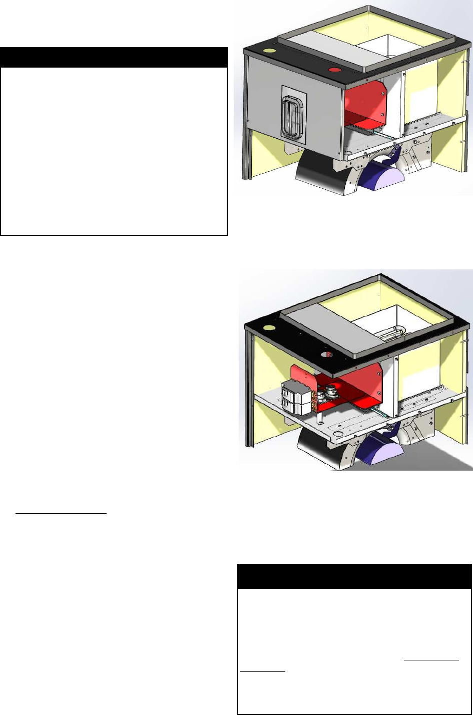
Electric Heater Accessory
The electric heater may be factory-installed or
field-installed. See Figures 5 through 8.
Removal Procedure:
To remove the electric heater,
1. Disconnect and lock out electrical power
from the unit. Remove heater access panel.
Disconnect power wires from the power
switch—DANGER! - MAKE SURE there is no
voltage on these wires before disconnecting!
2. Disconnect 2 harness connectors at the
blower deck.
3. Remove 2 screws holding heater support
feet to the blower deck.
4. Remove 4 screws that mount the heater to
the heater bulkhead. Handle heater carefully
to avoid damaging the wire heating elements.
Remove heater from the unit.
DANGER
WARNING: Hazardous voltage. Only qualified
personnel must install the electrical service. Dis-
connect and Lock Out all incoming power sources
before connecting to electrical service.
WARNING: This appliance must be permanently
grounded in accordance with the National Electrical
Code and local code requirements.
WARNING: For use with copper conductors only.
Fig. 5 — Heater Accessory Installed
(right side panel not shown)
Fig. 6 — Heater Accessory Installed
(right side and heater access panels
not shown)
035-000039-001 Page 16 of 38 MVA IOM 1.0 4-25-2014
INSTALLATION DANGER
WARNING: Hazardous voltage. Only qualified
personnel must install the electrical service. Dis-
connect and Lock Out all incoming power sources
before connecting to electrical service.
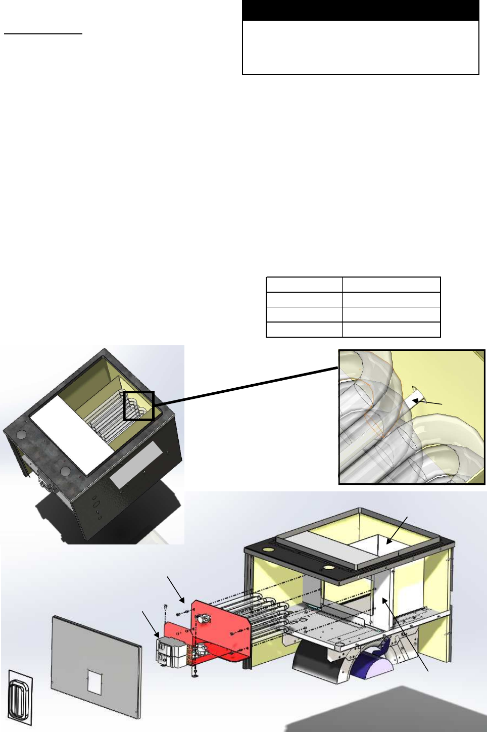
Install Procedure:
To install the electric heater,
1. Disconnect and lock out electrical power from
the unit. Remove heater access panel. Discon-
nect field power wires from the unit power wires.
DANGER! - MAKE SURE there is no voltage
supply to the unit before proceeding!
2. Disconnect and discard 1 harness connector at
the blower deck.
3. Remove blank plate from heater access panel
(covers square hole for breaker style power
switches).
4. Remove SAT sensor and sensor holder from
heater bulkhead and reposition on unit discharge
ductwork routing through auxiliary SAT sensor
hole on top panel.
5. Install SAT 3 feet after the first 90 degree turn
in the discharge ductwork.
6. Remove plate on the heater bulkhead (4
screws).
7. Install heater by carefully supporting the heater
and inserting it into the opening in the heater bulk-
head. NOTE: Make sure to guide the pin into the
hole at the back of the heater shroud. Secure the
heater to the bulkhead with 4 screws.
8. Connect 2 wiring harnesses (male) to the
matching female receptacles in the blower deck.
Fig. 7 — Heater Accessory Removal
(right side and heater access panels
not shown for clarity)
9. Connect field wiring to the breaker-style power
switches on the front of the heater. WARNING! Be
sure to provide the appropriate wire size and
branch circuit protection as required by the unit
nameplate!
10. Install the heater access panel.
11. Install the silicone cover “boot” over the top of
the power switches. This protects them from dust
buildup. The switches may be activated through the
flexible boot material.
12. Mark the nameplate label with the matching
heater kW rating. Label is located on the exterior of
the front top panel.
13. Update EEPROM settings to values shown in
the table. Refer to test run manual for detailed in-
structions for changing the EEPROM settings.
Fig. 8 — Heater
Accessory
Installed
PIN
HEATER
SHROUD
HEATER
ACCESS
PANEL
COVER
BOOT
HEATER
SHROUD
RIGHTSIDE
HEATER
ASSEMBLY
HEATER
BULKHEAD
POWER
SWITCH(ES)
Item Code New Settings
07 0001
38 0002
3C -001
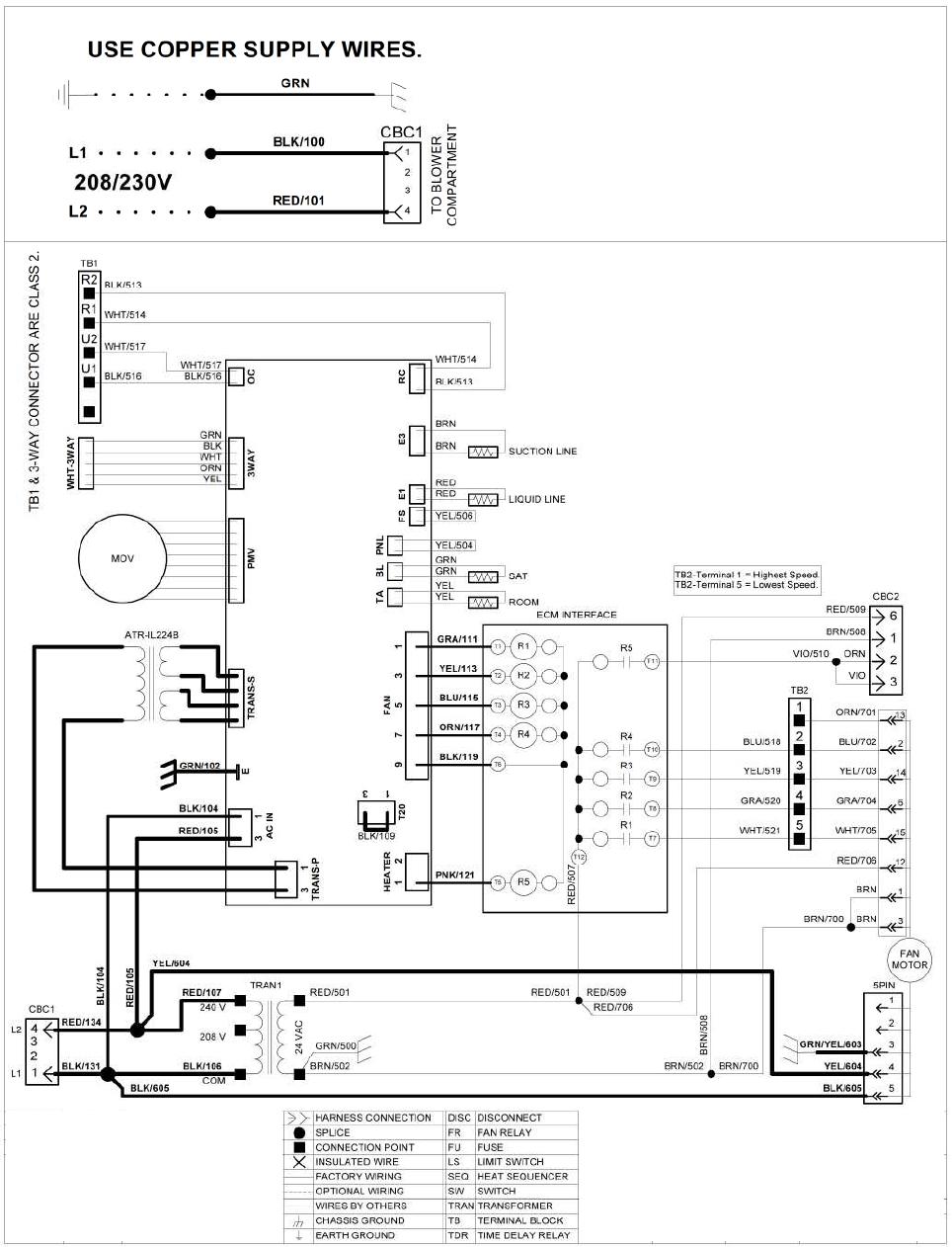
035-000039-001 Page 17 of 38 MVA IOM 1.0 4-25-2014
Typical wiring diagrams are shown on the following
pages FOR REFERENCE. Always refer to the wir-
ing diagram on the air handling unit for actual wir-
ing.
NOTE: CHECK MOTOR RATING PLATE FOR
CORRECT LINE VOLTAGE.
Connect electrical service to unit. Refer to unit wir-
ing diagram.
Power Wiring
For power supply connection, route field power wir-
ing L1 and L2 and connect either:
1. Unit Without EH: to field-provided and installed
disconnect switch and from switch to power
entry (unit side) and to unit power leads inside
the unit electrical section; or
2. Unit With EH: into the unit through power entry
(unit side) and then to the factory installed pow-
er switch inside the electrical section (see Fig-
ure 9). Note: power switch looks like a circuit
breaker but does not provide overload pro-
tection. Power switch provided only with elec-
tric heater (field kit or factory installed). NOTE:
When electric heat greater than 10kW is pro-
vided, two power supply circuits are required,
as shown on the wiring diagram.
Refer to nameplate or Electrical Ratings (page 30)
for FLA, maximum overcurrent protection device
(MOPD) and minimum circuit ampacity (MCA). Also
refer to wiring diagram affixed to unit to make con-
trol and power wiring connections. For new heater
installation, mark the nameplate label with the
matching heater kW rating. Label is located on the
exterior of the front top panel.
NOTE: Installer is responsible for power wiring and
branch circuit over current protection.
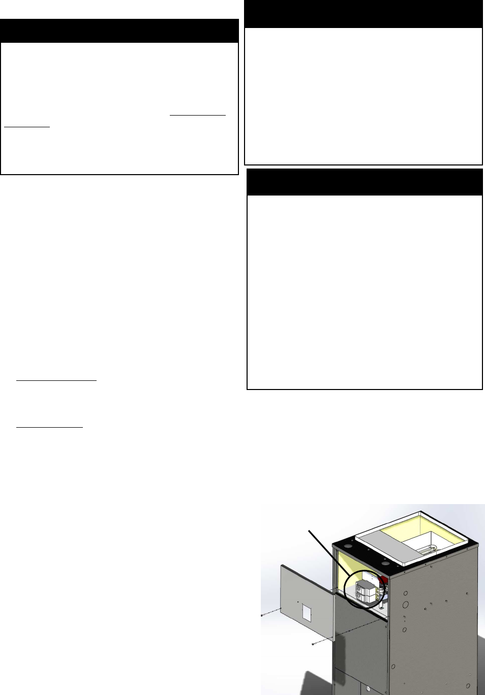
Control Voltage Wiring
Control voltage wiring may enter the unit at the con-
trol box located behind the blower access door, or
DANGER
NEVER enter an enclosed fan cabinet or reach into
a unit while the fan is running.
LOCK OPEN AND TAG the fan motor power dis-
connect switch before working on a fan. Take fuses
with you and note removal on tag. Electric shock
can cause personal injury or death.
LOCK OPEN AND TAG the electric heat coil power
disconnect switch before working on or near heat-
ers.
Failure to follow these warnings could lead to per-
sonal injury or death.
DANGER
WARNING: Hazardous voltage. Only qualified
personnel must install the electrical service. Dis-
connect and Lock Out all incoming power sources
before connecting to electrical service.
WARNING: This appliance must be permanently
grounded in accordance with the National Electrical
Code and local code requirements.
WARNING: For use with copper conductors only.
INSTALLATION-ELECTRICAL
Figure 9
Unit with Electric Heat
CAUTION
Use only copper conductors for field-installed elec-
trical wiring. Unit terminals are not designed to
accept other types of conductors.
Do not allow wiring to touch the refrigerant tubing,
compressor, or any moving parts of the fan.
Make wiring connections in accordance with the
system wiring system diagram and these instruc-
tions. Wrong wiring may cause improper operation
or unit damage!
Unauthorized changes in the internal wiring can be
very dangerous. The manufacturer will accept no
responsibility for any damage or malfunction that
occurs as a result of such unauthorized changes.
other convenient location. Control voltage wiring
leads exit the bottom of the control box and are
ready for field-connection.
CAUTION! To prevent malfunction of the air condi-
tioner caused by electrical noise, route control wiring
and inter-unit control wiring SEPARATELY FROM
THE POWER WIRING!
POWER
SWITCH
035-000039-001 Page 18 of 38 MVA IOM 1.0 4-25-2014
DANGER
WARNING: Hazardous voltage. Only qualified
personnel must install the electrical service. Dis-
connect and Lock Out all incoming power sources
before connecting to electrical service.
WARNING: This appliance must be permanently
grounded in accordance with the National Electrical
Code and local code requirements.
WARNING: For use with copper conductors only.
INSTALLATION-ELECTRICAL
General
Provide strain relief where field wiring passes
through cabinet. Wiring within the cabinet has
been positively located and supported so that it
does not pass over sharp metal edges or come in
contact with moving parts. After servicing, position
wiring properly in the original supports.
All field-installed wiring, including the electrical
ground, MUST comply with the National Electrical
Code (NEC) as well as applicable local codes. In
addition, all field wiring must conform to the Class
II temperature limitations described in the NEC.
Refer to factory wiring diagrams installed in the
unit. Use the MCA and MOPD from the nameplate
or electric heat nameplate or Electrical Ratings
(page 30) to size power supply wiring and overcur-
rent protection device. Installation must comply
with NEC and local codes.
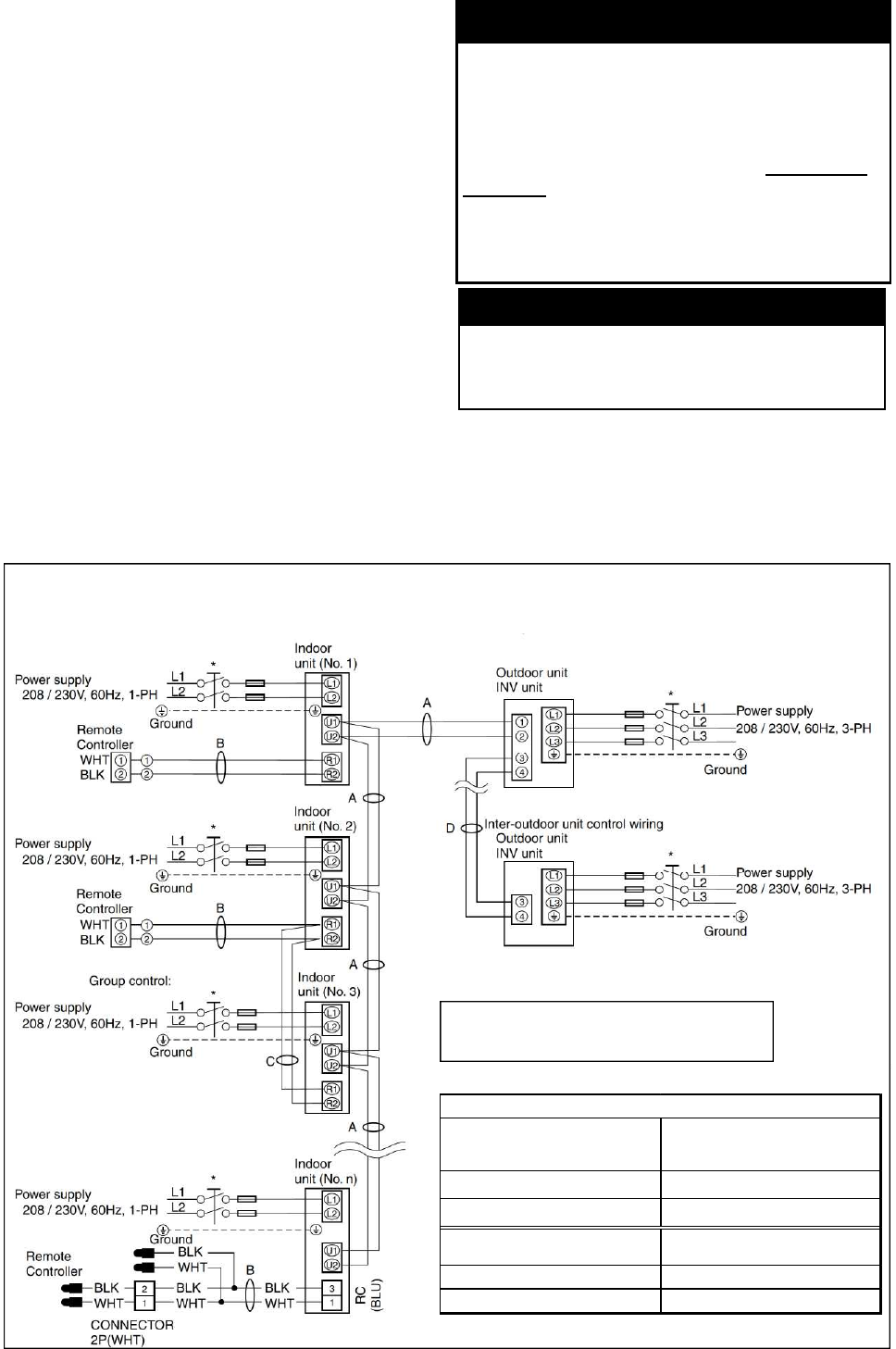
For communicating controls, refer to Figures 10
through 13 for max lengths, sizing and intercon-
nections. Refer to the condensing unit opera-
tion manual for more details.
Figure 10
Building System Wiring Diagram
(multiple indoor & outdoor units)
(A) Inter- unit (betwe en
outdoor a nd indoor units)
control wiring
(B) Re mote control wiring
AWG #18 (0.75 mm2) AWG #18 (0.75 mm2)
Max. 3,280 ft. Max. 1,640 ft.
(C) Control wiring for group
control
(D) Inter- outdoor unit
control wiring
AWG #18 (0.75 mm2) AWG #18 (0.75 mm2)
Max. 650 ft. (Total) Max. 980 ft.
Control wiring
NOTE: See table below for wire requirements
for lines above marked “A”, “B”, “C” and “D”.
CAUTION
Loose wiring may cause the terminal to overheat
or result in unit malfunction or cause a fire hazard.
Insure that all wiring is tightly connected!
035-000039-001 Page 19 of 38 MVA IOM 1.0 4-25-2014
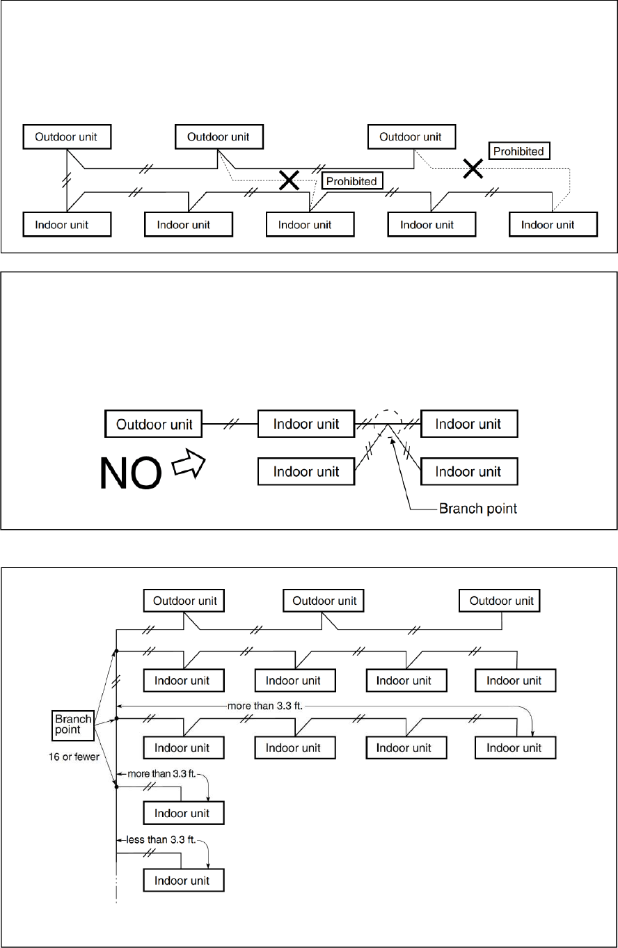
INSTALLATION-ELECTRICAL
Figure 11
Inter-Unit Control Wiring
Do not install the inter-unit control wiring
in a way that forms a loop.
Figure 12
Inter-Unit Control Wiring
Do not install inter-unit control wiring with splic-
es or “star branch” pattern. Star branch wiring
causes misaddress setting errors.
If branching the inter-unit control wiring,
the number of branch points should be
16 or fewer. (Branches less than 3.3 ft.
are not included in the total branch num-
ber.)
Figure 13
Branched Inter-Unit Control Wiring
035-000039-001 Page 20 of 38 MVA IOM 1.0 4-25-2014
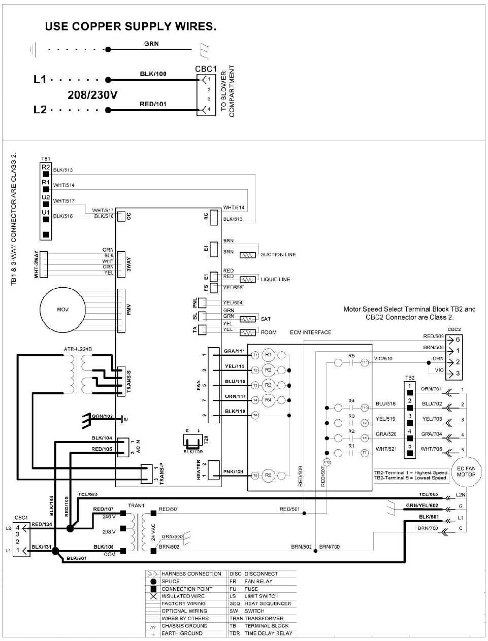
INSTALLATION-ELECTRICAL (cont’d)
TYPICAL WIRING DIAGRAM—
Unit sizes 18 & 24
TYPICAL WIRING—MVA18, MVA24
035-000039-001 Page 21 of 38 MVA IOM 1.0 4-25-2014
INSTALLATION-ELECTRICAL (cont’d)
TYPICAL WIRING DIAGRAM—
Unit sizes 30, 36, 42, 48 & 60
TYPICAL WIRING—MVA30, MVA36,
MVA42, MVA48, MVA60
035-000039-001 Page 22 of 38 MVA IOM 1.0 4-25-2014
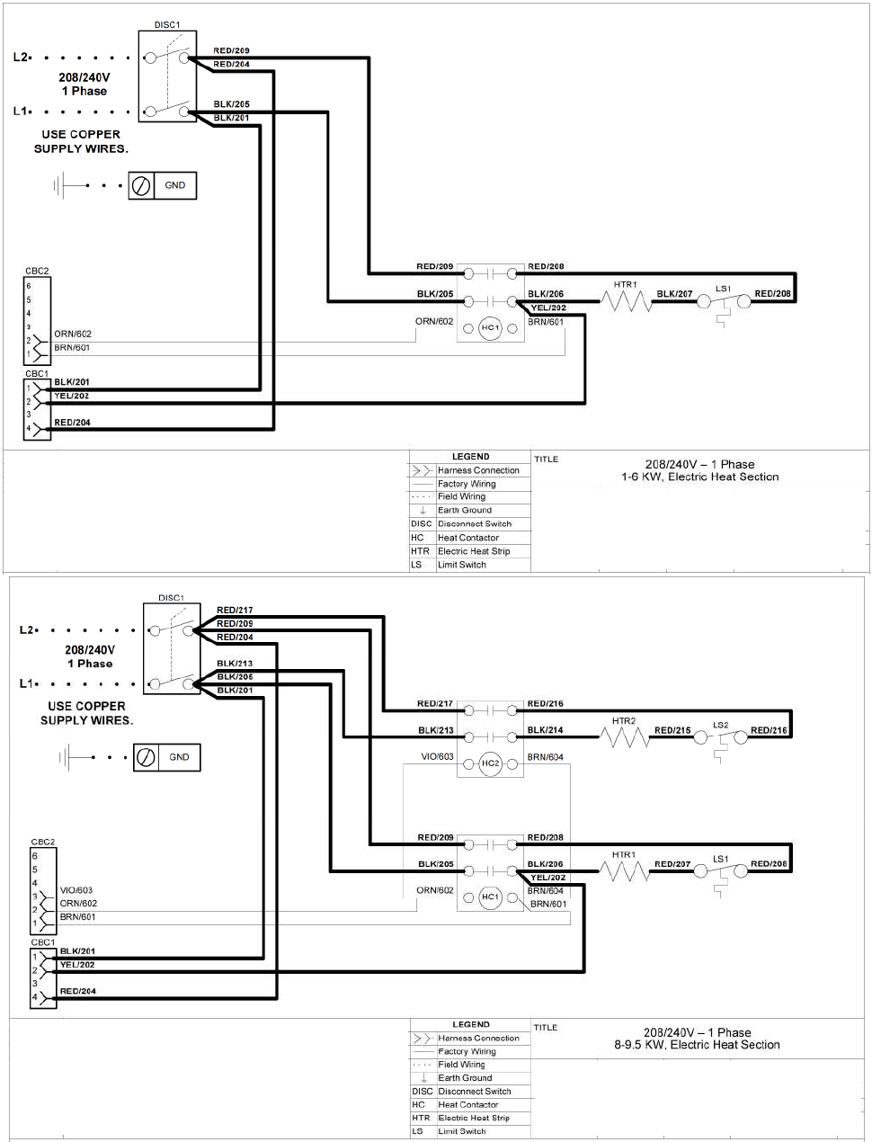
INSTALLATION-ELECTRICAL (cont’d)
TYPICAL WIRING—ELECTRIC HEAT
TYPICAL WIRING DIAGRAMS—
Electric Heat: 1-6kW and 8-9.5kW
TYPICAL WIRING—ELECTRIC HEAT
035-000039-001 Page 23 of 38 MVA IOM 1.0 4-25-2014
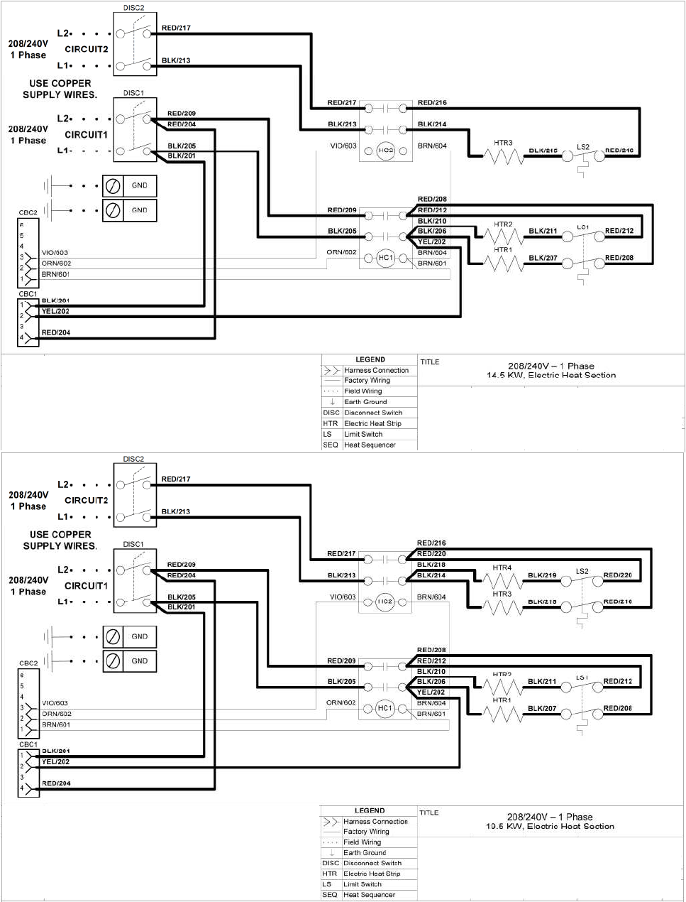
INSTALLATION-ELECTRICAL (cont’d)
TYPICAL WIRING—ELECTRIC HEAT
TYPICAL WIRING DIAGRAMS—
Electric Heat: 14.5kW and 19.5kW
TYPICAL WIRING—ELECTRIC HEAT
035-000039-001 Page 24 of 38 MVA IOM 1.0 4-25-2014
START-UP
Pre-Startup
Building Envelope—All building windows and doors should
be installed and closed before starting unit. During summer
construction, avoid unit sweating by allowing for gradual pull
down: use reduced capacity and use maximum available
airflow.
Temperature Controls-Check that unit is connected to the
controls system and communicating properly.
Outside Air and Freeze Protection
WARNING: Insure that the property is protected against
freezing conditions Failure to provide freeze protection
may result in property damage. Freeze protection
measures are customer-provided and installed and include
but are not limited to low-limit thermostats, automatic temper-
ature controls, and outside air dampers.
Startup
1. Insure electrical installation agrees with the unit name-
plate (voltage, branch circuit protection, wire size).
2. Close all panels and access doors. Make sure filter me-
dia is clean before starting unit. Replace filter if neces-
sary.
3. Verify that discharge ductwork and input plenum are in
place and secure.
4. Apply power to unit. If unit is equipped with on-board
power switch(es), turn switch(es) to the “On” position.
5. Insure that controls system has power and is operational.
6. Force control system to send fan on signal and speed
signal. Refer to unit wiring diagram and electrical section
for fan speed control arrangement.
7. Fan should start and run. Make sure fan operates with-
out significant noise or vibration.
8. Allow control system to start condensing unit, or as re-
quired for the installation.
9. Complete the checklist on the Start-Up Report.
10. Follow additional startup procedures for the system as
required by the condensing unit.
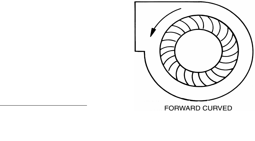
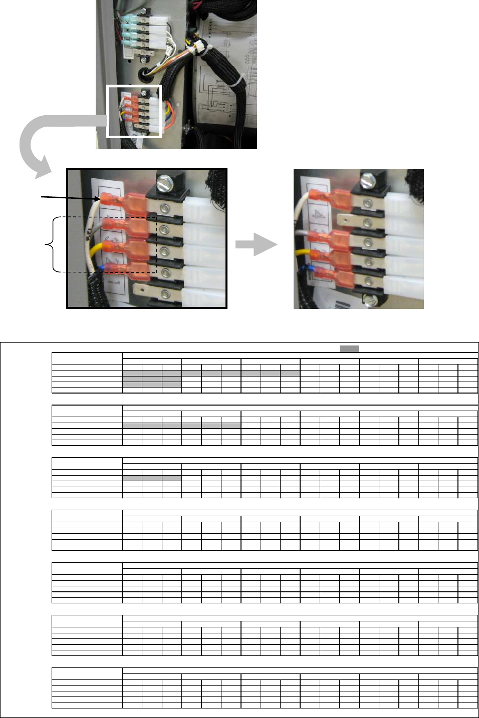
Fan Airflow Step-Up
If the duct system ESP is higher than planned and increased
Air Handler ESP is needed, shift the terminals as shown in
Figure 15.
Refer to Airflow tables and curves for airflow performance.
Fig. 14 — Fan Wheel Rotation—
FORWARD CURVED FAN
035-000039-001 Page 25 of 38 MVA IOM 1.0 4-25-2014
MVA18 Areas not recommend for operation due to excess velocity
Fan Setting RPM SCFM WATTS RPM SCFM WATTS RPM SCFM WATTS RPM SCFM WATTS RPM SCFM WATTS RPM SCFM WATTS
High Top 969 833 188 1022 804 197 1067 780 206 1132 743 215 1173 711 222 1201 666 224
High 902 774 156 955 749 163 1016 717 173 1067 690 181 1102 656 193 1144 611 201
Medium 898 772 152 960 737 160 1012 711 169 1091 669 176 1132 633 182 1158 569 187
Low 827 711 116 897 670 123 956 641 131 1050 596 137 1090 555 142 1115 473 149
MVA24
Fan Setting RPM SCFM WATTS RPM SCFM WATTS RPM SCFM WATTS RPM SCFM WATTS RPM SCFM WATTS RPM SCFM WATTS
High Top 1236 1052 394 1265 1034 396 1301 996 383 1327 953 345 1351 897 340 1430 838 261
High 1109 959 284 1155 929 296 1198 908 302 1233 882 311 1284 849 319 1304 780 302
Medium 969 833 188 1022 804 197 1067 780 206 1132 743 215 1173 711 222 1201 666 224
Low 902 774 156 955 749 163 1016 717 173 1067 690 181 1102 656 193 1144 611 201
MVA30
Fan Setting RPM SCFM WATTS RPM SCFM WATTS RPM SCFM WATTS RPM SCFM WATTS RPM SCFM WATTS RPM SCFM WATTS
High Top 828 1263 275 851 1221 287 865 1186 286 898 1142 301 922 1105 306 915 1082 309
High 764 1160 219 795 1114 224 819 1076 239 843 1037 241 825 1014 243 874 975 251
Medium 708 1064 171 737 1017 175 758 973 178 794 932 190 785 886 194 856 844 204
Low 630 940 121 663 892 125 693 835 130 730 797 138 750 743 143 806 696 152
MVA36
Fan Setting RPM SCFM WATTS RPM SCFM WATTS RPM SCFM WATTS RPM SCFM WATTS RPM SCFM WATTS RPM SCFM WATTS
High Top 934 1425 406 943 1396 414 966 1358 417 988 1319 426 1005 1279 432 1032 1246 440
High 881 1342 393 900 1311 347 920 1271 356 939 1229 356 967 1195 365 986 1160 370
Medium 764 1160 219 795 1114 224 819 1076 239 843 1037 241 825 1014 243 874 975 251
Low 708 1064 171 737 1017 175 758 973 178 794 932 190 785 886 194 856 844 204
MVA42
Fan Setting RPM SCFM WATTS RPM SCFM WATTS RPM SCFM WATTS RPM SCFM WATTS RPM SCFM WATTS RPM SCFM WATTS
High Top 967 1722 525 985 1679 529 1009 1642 541 1029 1597 546 1050 1557 558 1071 1510 567
High 835 1475 332 862 1425 343 890 1388 353 918 1335 365 940 1287 372 970 1238 370
Medium 760 1311 248 784 1271 258 803 1229 263 834 1195 274 870 1151 286 900 1114 290
Low 717 1228 211 742 1184 218 767 1140 225 803 1099 236 840 1046 246 878 994 254
MVA48
Fan Setting RPM SCFM WATTS RPM SCFM WATTS RPM SCFM WATTS RPM SCFM WATTS RPM SCFM WATTS RPM SCFM WATTS
High Top 1057 1894 1040 1080 1872 1031 1093 1816 1020 1104 1764 1010 1109 1685 990 1122 1629 975
High 967 1722 525 985 1679 529 1009 1642 541 1029 1597 546 1050 1557 558 1071 1510 567
Medium 835 1475 332 862 1425 343 890 1388 353 918 1335 365 940 1287 372 970 1238 370
Low 760 1311 248 784 1271 258 803 1229 263 834 1195 274 870 1151 286 900 1114 290
MVA60
Fan Setting RPM SCFM WATTS RPM SCFM WATTS RPM SCFM WATTS RPM SCFM WATTS RPM SCFM WATTS RPM SCFM WATTS
High Top 982 2323 1010 1010 2269 1040 1037 2222 1050 1064 2180 1070 1093 2132 1090 1115 2092 1110
High 878 2082 699 909 2027 711 946 1959 733 979 1932 754 1007 1889 771 1038 1844 791
Medium 760 1793 427 807 1716 450 825 1667 466 873 1623 488 913 1577 506 956 1517 520
Low 689 1603 314 724 1544 326 761 1489 342 805 1425 362 846 1373 380 890 1335 400
NOTES:
1. Data at sea level w/ 1" throw-away filter and dry coil.
ESP
0.000 0.100 0.200 0.300 0.400 0.500
ESP
0.000 0.100 0.200 0.300 0.400 0.500
ESP
0.000 0.100 0.200 0.300 0.400 0.500
ESP
0.000 0.100 0.200 0.300 0.400 0.500
ESP
0.000 0.100 0.200 0.300 0.400 0.500
ESP
0.000 0.100 0.200 0.300 0.400 0.500
ESP
0.000 0.100 0.200 0.300 0.400 0.500
Figure 15
Increasing ESP setting
Stay
Shift all
three
down
As Shipped Higher Fan Setting
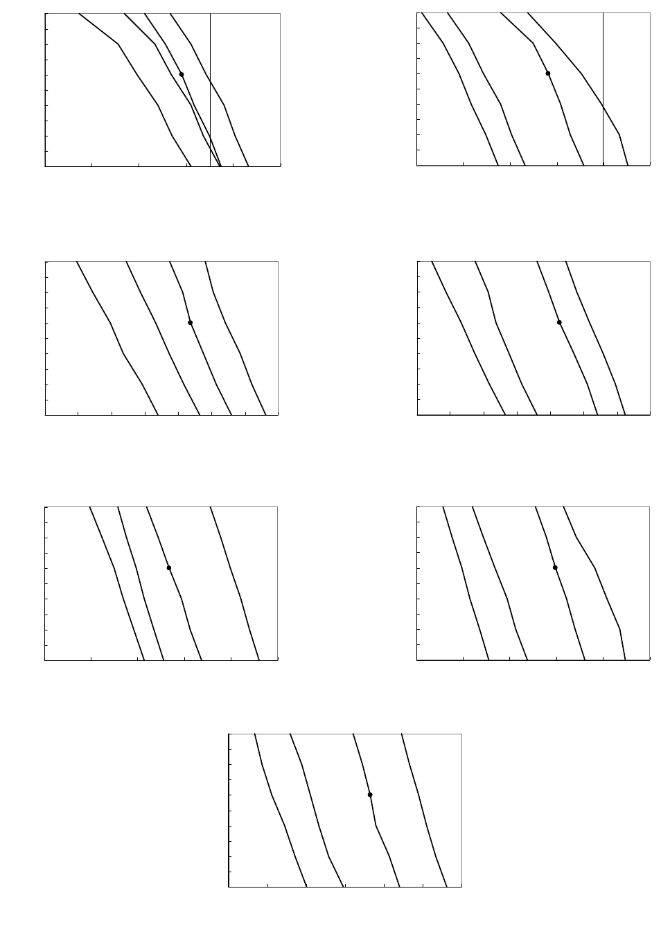
Airflow Performance
035-000039-001 Page 26 of 38 MVA IOM 1.0 4-25-2014
HTH
M
L
Area not recommended for use for
exessive airflow
0.00
0.05
0.10
0.15
0.20
0.25
0.30
0.35
0.40
0.45
0.50
400 500 600 700 800 900
Airflow (SCFM)
External Static Pressure (inch W.G.)
MVA18
HTHML
Area not recommended for use for
exessive airflow
0.00
0.05
0.10
0.15
0.20
0.25
0.30
0.35
0.40
0.45
0.50
600 700 800 900 1000 1100
Airflow (SCFM)
External Static Pressure (inch W.G.)
MVA24
HTHML
0.00
0.05
0.10
0.15
0.20
0.25
0.30
0.35
0.40
0.45
0.50
600 700 800 900 1000 1100 1200 1300
Airflow (SCFM)
External Static Pressure (inch W.G.)
MVA30
HTHML
0.00
0.05
0.10
0.15
0.20
0.25
0.30
0.35
0.40
0.45
0.50
800 900 1000 1100 1200 1300 1400 1500
Airflow (SCFM)
External Static Pressure (inch W.G.)
MVA36
HTHML
0.00
0.05
0.10
0.15
0.20
0.25
0.30
0.35
0.40
0.45
0.50
800 1000 1200 1400 1600 1800
Airflow (SCFM)
External Static Pressure (inch W.G.)
MVA42
HTHML
0.00
0.05
0.10
0.15
0.20
0.25
0.30
0.35
0.40
0.45
0.50
1000 1200 1400 1600 1800 2000
Airflow (SCFM)
External Static Pressure (inch W.G.)
MVA48
HTHML
0.00
0.05
0.10
0.15
0.20
0.25
0.30
0.35
0.40
0.45
0.50
1200 1400 1600 1800 2000 2200 2400
Airflow (SCFM)
External Static Pressure (inch W.G.)
MVA60
Airflow Performance Curves
035-000039-001 Page 27 of 38 MVA IOM 1.0 4-25-2014
SERVICE
General
1. Review Safety Considerations at beginning of
these instructions. Good safety habits are im-
portant tools when performing service proce-
dures.
2. To make speed measurements, use a laser-style
tachometer.
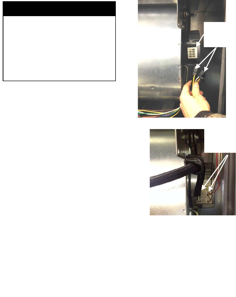
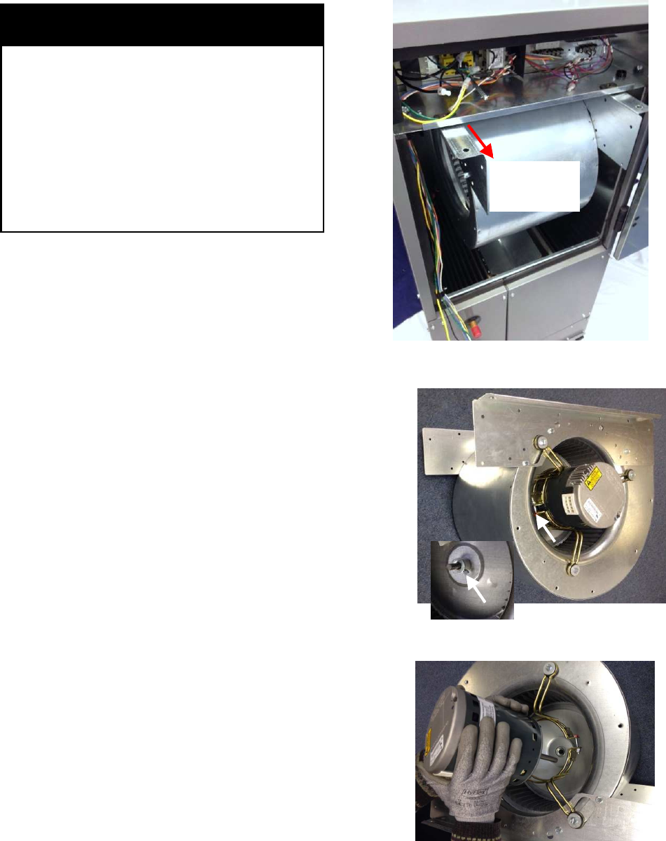
Fan Motor Replacement
WARNING: Shut off motor power and lock out power
supply.
Remove Blower/Motor Assembly
Procedure:
1. Disconnect wiring harness plugs from motor (Fig.
16 and 17).
2. Remove blower mounting bolts, which secure the
blower rails upward against the blower deck
(2ea).
3. Remove motor/wheel assembly from the AHU by
sliding out (Figure 18).
4. See Figure 19. Loosen shaft set screw (opposite
motor side) and motor mount tightening screw
until motor can be removed.
5. Remove motor. Install new motor (Fig. 20), tight-
en motor mount bolt, then locate fan wheel and
tighten shaft set screw.
6. Reverse steps 1-4 to reinstall fan. Make sure
that the two clips at the back hold the blower rails
up against the blower deck.
7. Spin fan by hand to make sure there is no rub-
bing or interference.
8. Close unit access doors, remove lockout/tag out
and restore the unit to operation.
DANGER
NEVER enter an enclosed fan cabinet or reach
into a unit while the fan is running.
LOCK OPEN AND TAG the fan motor power dis-
connect switch before working on a fan. Take fus-
es with you and note removal on tag. Electric
shock can cause personal injury or death.
LOCK OPEN AND TAG the electric heat coil pow-
er disconnect switch before working on or near
heaters.
Failure to follow these warnings could lead to per-
sonal injury or death.
Figure 16
Figure 17
MOTOR
HARNESS &
CONNECTORS
MOTOR
HARNESS &
CONNECTORS
035-000039-001 Page 28 of 38 MVA IOM 1.0 4-25-2014
Fan System Periodic Maintenance
1. The factory strongly recommends use of a Preven-
tive Maintenance program to insure that the unit
operates safely and efficiently.
2. Motor bearings are permanently sealed and do not
require lubrication.
3. Clean the fan’s flow area - maintenance interval in
accordance with the degree of contamination.
4. The fan wheel can be cleaned with a moist cloth.
5. Do not use any aggressive, paint solvent cleaning
agents when cleaning.
6. Never use a high-pressure cleaner or water-spray
for cleaning - particularly when the fan is running.
Coil Cleaning
DETERGENT — Spray mild detergent solution on
coils with garden-type sprayer. Rinse with fresh water.
Check to ensure condensate line is free. Excess water
from cleaning may flood unit if condensate line is
plugged.
DANGER
NEVER enter an enclosed fan cabinet or reach
into a unit while the fan is running.
LOCK OPEN AND TAG the fan motor power dis-
connect switch before working on a fan. Take fus-
es with you and note removal on tag. Electric
shock can cause personal injury or death.
LOCK OPEN AND TAG the electric heat coil pow-
er disconnect switch before working on or near
heaters.
Failure to follow these warnings could lead to per-
sonal injury or death.
Figure 18
MOTOR/
BLOWER
SLIDES OUT
Figure 19
Figure 20
035-000039-001 Page 29 of 38 MVA IOM 1.0 4-25-2014
SERVICE—Filters
Filters
FILTER SECTIONS — Open or remove
filter panel to replace old filter with a new
filter. See physical data tables for filter
data. See Figure 21.
Access Panels
The 3 sections of the unit can be reached
using the front access panels, removable
using 5/16” socket or driver or flat head
screwdriver. See Figure 22.
Figure 21
Figure 22
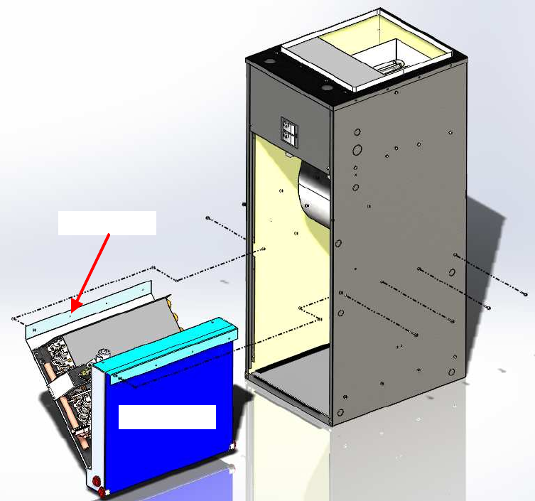
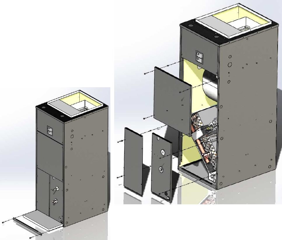
035-000039-001 Page 30 of 38 MVA IOM 1.0 4-25-2014
1. Perform procedure on the ground for safety. If
working at heights USE EXTREME CAUTION ob-
serve all FALL SAFETY considerations. Under all
conditions, LOCK OUT all power supplies before
performing this procedure. WARNING! Coil sec-
tion can be heavy—use proper lifting equipment.
2. Isolate coil and reclaim refrigerant. Disconnect
unit from piping. Remove supply piping to allow
access into the coil section from the front.
3. Remove blower access door and coil access
doors.
4. Carefully remove temperature sensors from the
coil and set them aside, clear of the coil & drain
pan assembly. Disconnect electronic expansion
valve (EEV) wiring from the EEV.
5. Remove 4 screws on the drain pan side of the
cabinet (right side shown in Fig. 23). Remove 4
screws from coil support side of the cabinet (left
side shown in Fig. 23).
6. Slide coil & drain pan assembly out of the unit (Fig
19).
7. Coil can be detached from drain pan using 5/16”
driver, 2 screws. Coil can be detached from coil
support using 5/16” driver, 4 screws.
8. Follow instructions in reverse to install new coil.
SERVICE-Coil Removal and Reinstallation Procedure
Figure 23
9. Re-install sensors back in original posi-
tions. CAUTION! Be sure to place sen-
sors in correct locations for proper unit
operation.
10. Re-install wiring to EEV.
11. Re-install unit access panels.
12. Return unit to service.
COIL SUPPORT
DRAIN PAN
035-000039-001 Page 31 of 38 MVA IOM 1.0 4-25-2014
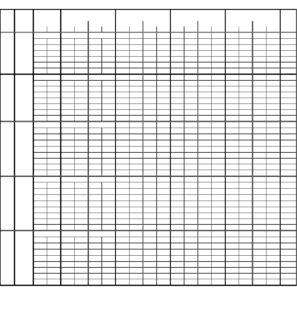
MVA Electrical Data
240
208
240
208
240
208
240
208
240
208
240
208
240
208
240
208
240
208
3.0 3.0 n/a n/a 3.8 3.8 n/a n/a 15 15 n/a n/a 14
1.0 0.8 4.2 3.6 0.0 0.0 7.2 6.6 n/a n/a 9.0 8.3 n/a n/a 15 15 n/a n/a 14
3.0 2.3 12.5 10.8 0.0 0.0 15.5 13.8 n/a n/a 19.4 17.3 n/a n/a 20 20 n/a n/a 12
5.0 3.8 20.8 18.1 0.0 0.0 23.8 21.1 n/a n/a 29.8 26.3 n/a n/a 30 30 n/a n/a 10
6.0 4.5 25.0 21.7 0.0 0.0 28.0 24.7 n/a n/a 35.0 30.8 n/a n/a 35 35 n/a n/a 8
8.0 6.0 33.3 28.9 0.0 0.0 36.3 31.9 n/a n/a 45.4 39.9 n/a n/a 50 40 n/a n/a 8
9.5 7.1 39.6 34.3 0.0 0.0 42.6 37.3 n/a n/a 53.2 46.6 n/a n/a 60 50 n/a n/a 6
3.6 3.6 n/a n/a 4.5 4.5 n/a n/a 15 15 n/a n/a 14
1.0 0.8 4.2 3.6 0.0 0.0 7.8 7.2 n/a n/a 9.7 9.0 n/a n/a 15 15 n/a n/a 14
3.0 2.3 12.5 10.8 0.0 0.0 16.1 14.4 n/a n/a 20.1 18.0 n/a n/a 25 20 n/a n/a 10
5.0 3.8 20.8 18.1 0.0 0.0 24.4 21.7 n/a n/a 30.5 27.1 n/a n/a 35 30 n/a n/a 8
6.0 4.5 25.0 21.7 0.0 0.0 28.6 25.3 n/a n/a 35.8 31.6 n/a n/a 40 35 n/a n/a 8
8.0 6.0 33.3 28.9 0.0 0.0 36.9 32.5 n/a n/a 46.2 40.6 n/a n/a 50 45 n/a n/a 8
9.5 7.1 39.6 34.3 0.0 0.0 43.2 37.9 n/a n/a 54.0 47.4 n/a n/a 60 50 n/a n/a 6
14.5 10.9 39.6 34.3 20.8 18.1 43.2 37.9 20.8 18.1 54.0 47.4 26.0 22.6 60 50 30 25 6
4.9 4.9 n/a n/a 6.1 6.1 n/a n/a 15 15 n/a n/a 14
1.0 0.8 4.2 3.6 0.0 0.0 9.1 8.5 n/a n/a 11.3 10.6 n/a n/a 15 15 n/a n/a 14
3.0 2.3 12.5 10.8 0.0 0.0 17.4 15.7 n/a n/a 21.8 19.7 n/a n/a 25 20 n/a n/a 10
5.0 3.8 20.8 18.1 0.0 0.0 25.7 23.0 n/a n/a 32.2 28.7 n/a n/a 35 30 n/a n/a 10
6.0 4.5 25.0 21.7 0.0 0.0 29.9 26.6 n/a n/a 37.4 33.2 n/a n/a 40 35 n/a n/a 8
8.0 6.0 33.3 28.9 0.0 0.0 38.2 33.8 n/a n/a 47.8 42.2 n/a n/a 50 45 n/a n/a 8
9.5 7.1 39.6 34.3 0.0 0.0 44.5 39.2 n/a n/a 55.6 49.0 n/a n/a 60 50 n/a n/a 6
14.5 10.9 39.6 34.3 20.8 18.1 44.5 39.2 20.8 18.1 55.6 49.0 26.0 22.6 60 50 30 25 6
19.5 14.6 39.6 34.3 41.7 36.1 44.5 39.2 41.7 36.1 55.6 49.0 52.1 45.1 60 50 60 50 6
6.0 6.0 n/a n/a 7.5 7.5 n/a n/a 15 15 n/a n/a 14
1.0 0.8 4.2 3.6 0.0 0.0 10.2 9.6 n/a n/a 12.7 12.0 n/a n/a 15 15 n/a n/a 14
3.0 2.3 12.5 10.8 0.0 0.0 18.5 16.8 n/a n/a 23.1 21.0 n/a n/a 25 25 n/a n/a 10
5.0 3.8 20.8 18.1 0.0 0.0 26.8 24.1 n/a n/a 33.5 30.1 n/a n/a 35 35 n/a n/a 10
6.0 4.5 25.0 21.7 0.0 0.0 31.0 27.7 n/a n/a 38.8 34.6 n/a n/a 40 35 n/a n/a 8
8.0 6.0 33.3 28.9 0.0 0.0 39.3 34.9 n/a n/a 49.2 43.6 n/a n/a 50 45 n/a n/a 8
9.5 7.1 39.6 34.3 0.0 0.0 45.6 40.3 n/a n/a 57.0 50.4 n/a n/a 60 60 n/a n/a 6
14.5 10.9 39.6 34.3 20.8 18.1 45.6 40.3 20.8 18.1 57.0 50.4 26.0 22.6 60 60 30 25 6
19.5 14.6 39.6 34.3 41.7 36.1 45.6 40.3 41.7 36.1 57.0 50.4 52.1 45.1 60 60 60 50 6
7.6 7.6 n/a n/a 9.5 9.5 n/a n/a 15 15 n/a n/a 14
1.0 0.8 4.2 3.6 0.0 0.0 11.8 11.2 n/a n/a 14.7 14.0 n/a n/a 15 15 n/a n/a 14
3.0 2.3 12.5 10.8 0.0 0.0 20.1 18.4 n/a n/a 25.1 23.0 n/a n/a 30 25 n/a n/a 10
5.0 3.8 20.8 18.1 0.0 0.0 28.4 25.7 n/a n/a 35.5 32.1 n/a n/a 40 35 n/a n/a 8
6.0 4.5 25.0 21.7 0.0 0.0 32.6 29.3 n/a n/a 40.8 36.6 n/a n/a 45 40 n/a n/a 8
8.0 6.0 33.3 28.9 0.0 0.0 40.9 36.5 n/a n/a 51.2 45.6 n/a n/a 60 50 n/a n/a 6
9.5 7.1 39.6 34.3 0.0 0.0 47.2 41.9 n/a n/a 59.0 52.4 n/a n/a 60 60 n/a n/a 6
14.5 10.9 39.6 34.3 20.8 18.1 47.2 41.9 20.8 18.1 59.0 52.4 26.0 22.6 60 60 30 25 6
19.5 14.6 39.6 34.3 41.7 36.1 47.2 41.9 41.7 36.1 59.0 52.4 52.1 45.1 60 60 60 50 6
Notes:
*1. Minimum Wire Gauge is based upon Circuit 1 ampacity and the use of 75C wire at the unit.
2. 14.5kW and 19.5kW Heating units require two supply circuits.
3. MVA18/24 use ECM 5.0 motor. MVA30/36/42/48/60 use ECM-VE motor.
NONE
CIRCUIT 1
MVA
Unit
Size
MOTOR
FLA
240-
208V
NONE NONE NONE
NONE
NONE
18/24 3.0
60
NONE NONE
MIN
WIRE
SIZE
AWG*
CIRCUIT 1 CIRCUIT 2 CIRCUIT 1 CIRCUIT 2 CIRCUIT 1 CIRCUIT 2
MINIMUM CIRCUIT
AMPACITY
CIRCUIT 2
ELECTRIC HEAT AMPS
42
48
7.6
NONE NONE
30/36
NONE NONE
4.9
3.6
UNIT FLA Maximum Overcurrent
Protective Device (A)
6.0
NONE NONE
NONE
TOTAL
ELECTRIC
HT (KW)
UNIT ELECTRICAL RATINGS
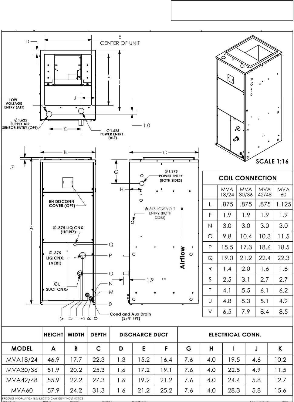
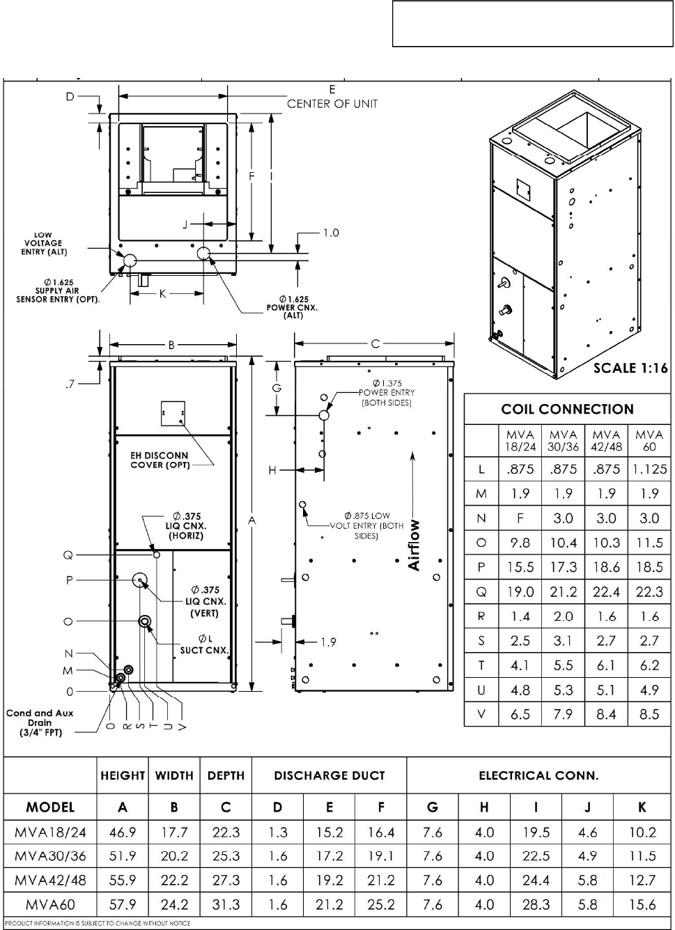
035-000039-001 Page 32 of 38 MVA IOM 1.0 4-25-2014
UNIT DIMENSIONS MVA18-60 Elec Heat Ready
RH Drain Connections—Configuration B
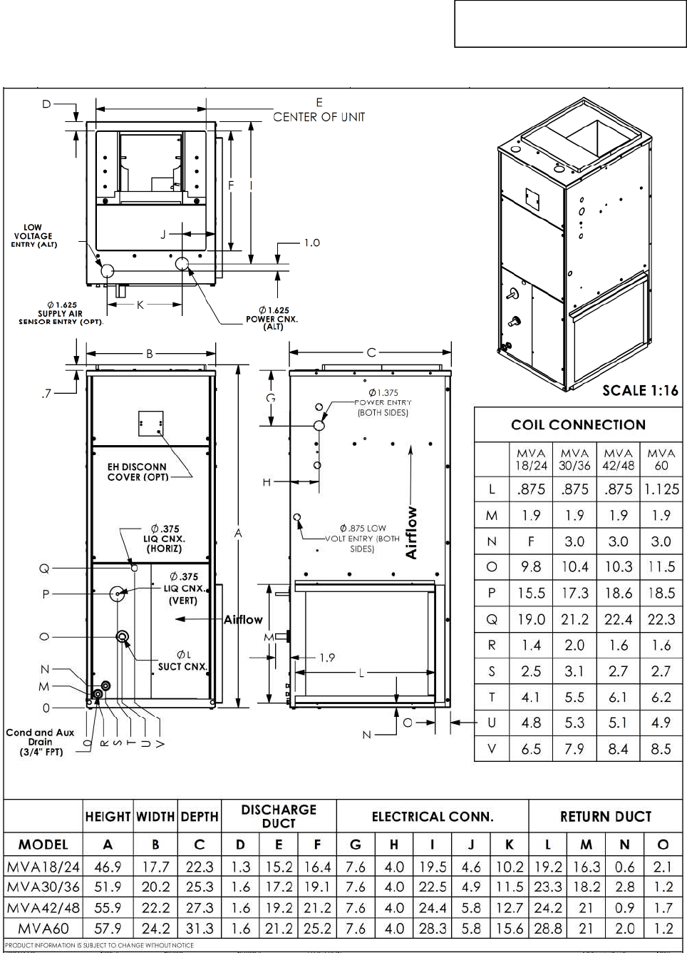
035-000039-001 Page 33 of 38 MVA IOM 1.0 4-25-2014
UNIT DIMENSIONS MVA18-60 Elec Heat Ready
LH Drain Connections—Configuration T
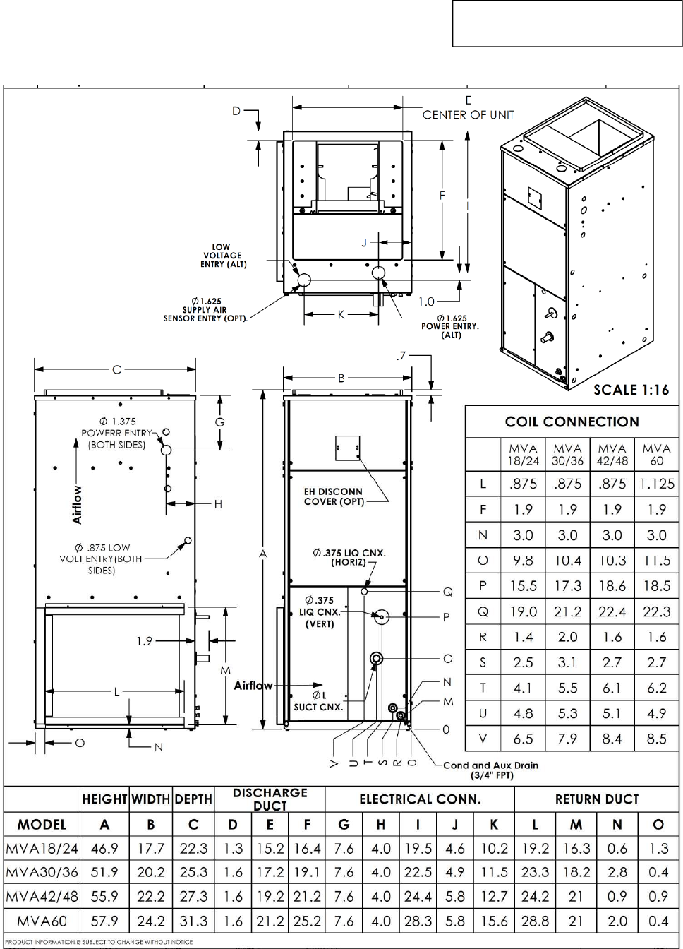
035-000039-001 Page 34 of 38 MVA IOM 1.0 4-25-2014
UNIT DIMENSIONS MVA18-60 Elec Heat Ready
RH Return — Configuration R
035-000039-001 Page 35 of 38 MVA IOM 1.0 4-25-2014
UNIT DIMENSIONS MVA18-60 Elec Heat Ready
LH Return — Configuration L
035-000039-001 Page 36 of 38 MVA IOM 1.0 4-25-2014
THIS PAGE INTENTIONALLY LEFT BLANK
035-000039-001 Page 37 of 38 MVA IOM 1.0 4-25-2014
MVA Series Air Handling Unit
Start-up Report
STARTUP REPORT
Group Checklist Item Yes No
Electrical/
Operational
Does electrical service correspond to unit nameplate?
-Nameplate Supply Voltage/Phase: Rated_________ Measured___________
-Nameplate Rated FLA motor current: Rated_______ Measured__________
Does all field wiring conform to unit wiring diagram?
Is field-provided freeze protection present? (if required)
Is fan wheel turning the correct direction?
Is the filter clean?
Structural
Is unit properly supported?
Is unit installed level (necessary for proper condensate drainage)?
Is properly sized condensate trap present?
Is the condensate disposal system operating correctly?
Is auxiliary external condensate drain pan installed or auxiliary drain connection
utilized as recommended by IOM? (not required for valid warranty)
Piping Check
Is the DX system charged per the condensing unit instructions?
Is unit piping correct and insulated to prevent condensation?
Are the refrigerant pipe lines properly insulated?
Are there any leaks detected: interior to unit or at connections?
CRITICAL! For Horizontal Unit Orientation: Is the EEV in vertical orientation?
Job Name City
Sales Order # Unit Tag
Model Number Serial Number
Installer Quantity of Units

035-000039-001 Page 38 of 38 MVA IOM 1.0 4-25-2014
MVA Series Air Handling Unit
Installation, Operation and Maintenance Manual
