Panoramic Power PAN-4-2 Wireless Power Sensor PAN-42 User Manual PAN 42 User Guide
Panoramic Power ltd. Wireless Power Sensor PAN-42 PAN 42 User Guide
UserManual.wiki
>
Panoramic Power
>
PAN 4 2 User Manual
Users Manual
Navigation menu
Upload a User Manual
Namespaces
Wiki Guide
HTML
PDF
Info
Views
User Manual
Discussion / Help
Navigation


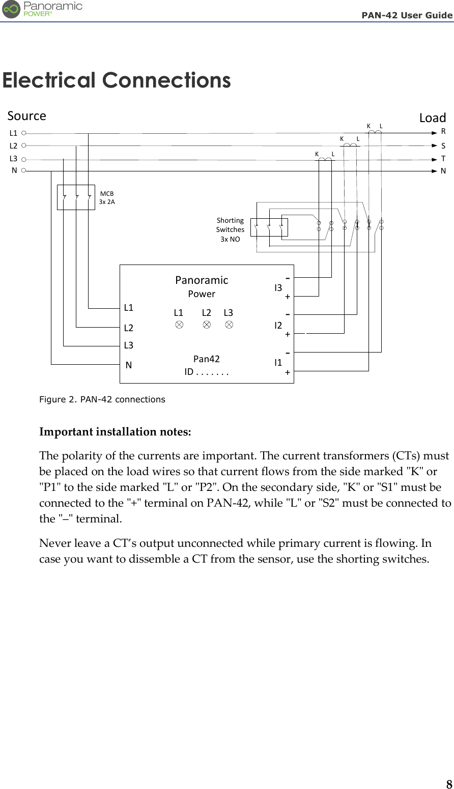
![PAN-42 User Guide 11 Uninstalling a Sensor Put the MCBs on the phase lines in their open position, and the CT shorting switches in their closed position. Then disconnect the current and voltage inputs from the PAN-42 sensor and remove it from the electrical panel. Sensor Specifications PAN-42 Specifications 4-wire Wye, 3-wire Delta, single-phase 3-wire, single-phase 2-wire, or dual-phase 3-wire configurations Voltage: [120V / 208V], [240V / 416V], or [277V / 480V] Frequency: 48-62 Hz CT current input: standard 0-5 Amms. Current measurement range: Depending on CT ratio Minimum current (at device input) ≤ 0.05 Arms (1% of full scale) Outputs: o Active Energy (kWh) – accumulated o True RMS Voltage/Current – per phase o Active/Reactive Power – per phase o Power Factor – per phase o Total Harmonic Distortion (%) – per phase (Voltage and Current) o Frequency Accuracy (for Voltage, Current and Active Energy) According to IEC687 (Class 0.5)* According to ANSI C12.20 (Class 0.5)* *Assuming CT of class 0.2 or better Pulse output 2 optically isolated outputs for active and reactive energy (kWh) Transmission frequency 434 MHz (EU) 915 MHz (US) Transmission power (ERP)* 0 dBm (Max) Transmission interval 10 seconds](https://usermanual.wiki/Panoramic-Power/PAN-4-2/User-Guide-2288951-Page-11.png)