Panoramic Power PAN-4-2 Wireless Power Sensor PAN-42 User Manual PAN 42 User Guide
Panoramic Power ltd. Wireless Power Sensor PAN-42 PAN 42 User Guide
Users Manual

Panoramic Power® System
PAN-42 User Guide

PAN-42 User Guide
2
Copyright Notice
Copyright © 2014 Panoramic Power Ltd. All rights reserved.
PANORAMIC POWER® is a registered trademark of Panoramic Power Ltd. All
other trademarks are the property of their respective owners
FCC Compliance Statement
This device has been tested and found to comply with the limits for a Class B
digital device, pursuant to Part 15 of the FCC Rules. These limits are designed
to provide reasonable protection against harmful interference in residential
installations. This equipment generates uses and can radiate radio frequency
energy and, if not installed and used in accordance with the instructions, may
cause harmful interference to radio and television reception.
However, there is no guarantee that interference will not occur in a particular
installation. If this device does cause such interference, which can be verified by
turning the device off and on, the user is encouraged to eliminate the
interference by one or more of the following measures:
Re-orient or re-locate the receiving antenna.
Increase the distance between the device and the receiver.
Connect the device to an outlet on a circuit different from the one that
supplies power to the receiver.
Consult the dealer or an experienced radio/TV technician.
WARNING! Changes or modifications to this unit not expressly approved by
the party responsible for compliance could void the user’s authority to operate
the equipment.

PAN-42 User Guide
3
FCC Declaration of Conformity
Trade Name: Panoramic Power
Product Name: Wireless Power Sensor
Product Model Number: PAN-42-US
This device complies with Part 15 of the FCC Rules. Operation is subject to the
following two conditions:
(1) This device may not cause harmful interference, and
(2) this device must accept any interference received, including interference that
may cause undesired operation.
Responsible Party
Name: Panoramic Power Inc.
Address: 44 W. 28th Street, 8th Floor, New York, NY, 10001
Telephone: +1-646-794-4240
Manufacturer
Name: Panoramic Power Ltd.
Address: 20 Atir Yeda St., Kfar Saba 44643, Israel
Telephone: +972-9-7667600
Date: _June 2 2014__ Signature: _________________________________________
Quality Assurance Manager of Manufacturer
Printed Name: ____Moran Pekin___________

PAN-42 User Guide
4
Contents
Overview ................................................................................................................ 5
Workflow ................................................................................................................ 5
Safety Precautions ................................................................................................. 5
Mechanical Installation ......................................................................................... 6
Electrical Connections........................................................................................... 8
Mapping the Site ................................................................................................... 9
Installing the Sensor .............................................................................................. 9
Registering the Installed Sensor ........................................................................ 10
Monitoring Sensor Activity ............................................................................... 10
Uninstalling a Sensor .......................................................................................... 11
Sensor Specifications ........................................................................................... 11
Certified CTs ........................................................................................................ 12
Support ................................................................................................................. 13

PAN-42 User Guide
5
Overview
The PAN-42 wireless power sensor provides
high-accuracy real-time power and power
quality measurements for mains power
monitoring, sub-metering and metering of
large loads.
Designed for demanding electrical
applications, supporting industry accuracy
standards, PAN-42 enables the metering of
power, voltage, current, power factor and
power quality measurement data.
Information is sent wirelessly, through Panoramic Power’s Bridge unit, to
Panoramic Power’s advanced cloud-based analytics platform. The data is then
used to provide customers with actionable analytics and real-time dashboards
and alerts.
Workflow
Sensor installation consists of the following steps:
1. Map the circuits.
See Panoramic Power Deployment Tool User Guide.
2. Physically attach the sensor and the CTs to the wires.
3. Monitors the proper functioning of the sensor. See Panoramic Power
Deployment Tool User Guide.
Safety Precautions
Read the instructions in this manual before installing, and take note of the
following precautions:
Ensure that all incoming AC power and other power sources are turned
OFF before performing any work or connecting the PAN-42. Failure to do
so may result in serious or even fatal injury and/or equipment damage.

PAN-42 User Guide
6
Under no circumstances should PAN-42 be connected to a power source if
it is damaged.
To prevent potential fire or shock hazard, do not expose PAN-42 to rain or
moisture.
Ensure that the external current transformers are shorted (by using the
recommended shorting switches) before disconnecting PAN42 from its
current inputs.
The sensor and CTs should be installed and removed only by a qualified
electrician. Read this manual thoroughly before connecting the device to the
current-carrying circuits.
During operation of the device, hazardous voltages are present on input
terminals. Failure to observe precautions can result in serious or even fatal
injury, or damage to equipment.
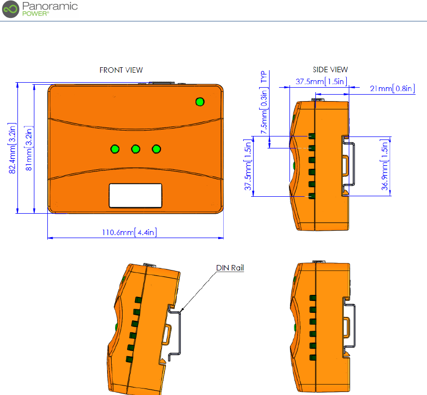
Mechanical Installation
There are several mounting options for PAN-42:
On a 35-mm DIN rail (see the drawing below)
By using screws, using the slots on the back of the device
With plastic tie-wraps, using the hooks on the back of the device
PAN-42 User Guide
7
Figure 1. Hardware measurements
PAN-42 User Guide
8
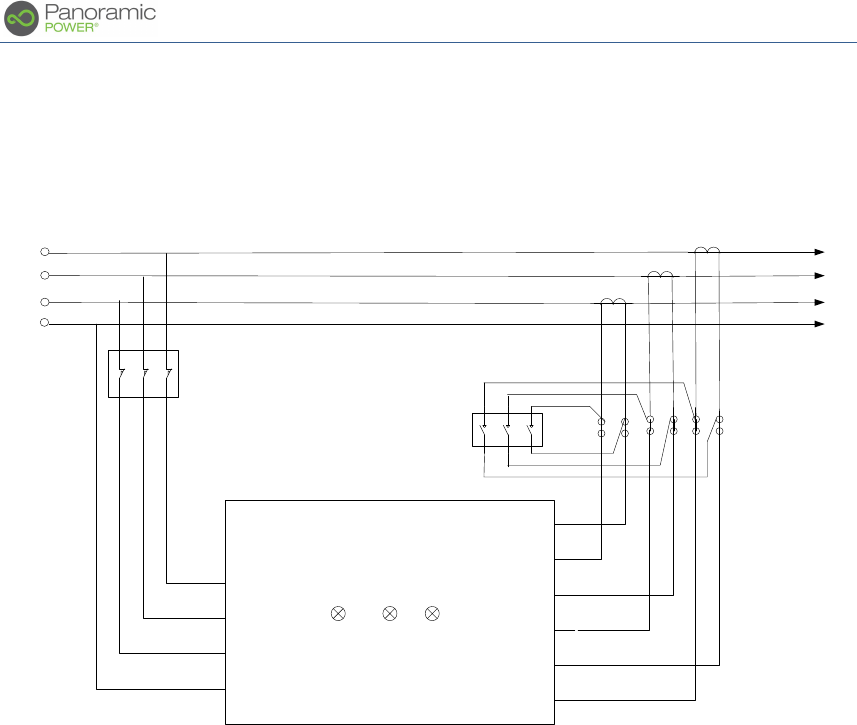
Electrical Connections
Figure 2. PAN-42 connections
Important installation notes:
The polarity of the currents are important. The current transformers (CTs) must
be placed on the load wires so that current flows from the side marked "K" or
"P1" to the side marked "L" or "P2". On the secondary side, "K" or "S1" must be
connected to the "+" terminal on PAN-42, while "L" or "S2" must be connected to
the "–" terminal.
Never leave a CT’s output unconnected while primary current is flowing. In
case you want to dissemble a CT from the sensor, use the shorting switches.
-
-
-
+
+
+
I1
I2
I3
N
L3
L2
L1 L1 L2 L3
Panoramic
Power
K L
L1
L2
L3
N
Load
K L
K L
Source
Shorting
Switches
3x NO
R
S
T
N
Pan42
ID . . . . . . .
MCB
3x 2A

PAN-42 User Guide
9
Mapping the Site
See Panoramic Power Deployment Guide.
Installing the Sensor
This procedure must be carried out by a certified electrician.
1. Make sure you connect the CTs through the shorting switches
2. Mount the CT(s) on the hot wire(s):
a. If the CT is split-core: Open the CT, and close it around the hot wire.
b. If the CT is solid-core: Disconnect one of the ends of the hot wire
from the panel, insert it through the CT, and then reconnect it to the
panel.
c. In both cases, make sure the CT is placed on the wire so that the
direction of current flow on the wire is from the side marked "P1" or
"K" on the CT, to the side marked "P2" or "L" on the CT.
3. Connect the three CTs to the inputs I1- I3, by performing the following
procedure to all three CTs:
a. Use 1.0-4.0mm2 (12-17 AWG) wires. Make sure that the wire gauge is
suitable for carrying 5Amms for the length of wire required, without
a significant voltage drop.
b. Connect the PAN-42 sensor's terminal marked as "+" to the CT's
terminal marked as "S1" or "K"
c. Connect the PAN-42 sensor's terminal marked as "–" to the CT's
terminal marked as "S2" or "L"
4. Connect the voltage inputs:
a. Connect one to three phases L1, L2, L3 (R, S, T) and the neutral wire
to the appropriate PAN-42 inputs, making sure each phase passes
through an MCB (see Figure 2).
b. Make sure that you use the same phase for the current and voltage
inputs; that is, L1 and I1 are for the same phase, L2 goes with I2, and
L3 goes with I3.

PAN-42 User Guide
10
c. Note: In order for the PAN-42 sensor to turn on, the neutral wire and
at least one voltage phase must be connected.
5. After connecting the current and voltage inputs, make sure that the three-
phase indication LEDs are steady green, and that the Tx LED flashes in
green.
6. For each phase, the LED indications are as follows:
Connection
LED Visual indication
Both voltage and current are
connected
Steady green
Only voltage is connected
Flashing green
Only current is connected
Flashing red
No voltage or current is connected
Off
7. Finalize the PAN-42 sensor and the CTs' position on the panel,
maintaining a reasonable distance between the CTs and PAN-42.
IMPORTANT NOTES:
Do not mount the CT on the hot wire before you have already connected its
outputs to the shorting switch (or to the PAN-42 sensor), and made sure the
switch is in its closed state!
If a PAN-42 sensor needs to be replaced, put the suggested shorting switches in
their closed states before PAN-42 is disconnected!
Do not leave the CT mounted/installed on a hot wire without being short
circuited.
Registering the Installed Sensor
See Panoramic Power Deployment Guide.
Monitoring Sensor Activity
See Panoramic Power Deployment Guide.

PAN-42 User Guide
11
Uninstalling a Sensor
Put the MCBs on the phase lines in their open position, and the CT shorting
switches in their closed position. Then disconnect the current and voltage
inputs from the PAN-42 sensor and remove it from the electrical panel.
Sensor Specifications
PAN-42 Specifications
4-wire Wye, 3-wire Delta, single-phase 3-wire, single-phase 2-wire,
or dual-phase 3-wire configurations
Voltage: [120V / 208V], [240V / 416V], or [277V / 480V]
Frequency: 48-62 Hz
CT current input: standard 0-5 Amms.
Current measurement range: Depending on CT ratio
Minimum current (at device input) ≤ 0.05 Arms (1% of full scale)
Outputs:
o Active Energy (kWh) – accumulated
o True RMS Voltage/Current – per phase
o Active/Reactive Power – per phase
o Power Factor – per phase
o Total Harmonic Distortion (%) – per phase (Voltage and
Current)
o Frequency
Accuracy (for Voltage, Current
and Active Energy)
According to IEC687 (Class 0.5)*
According to ANSI C12.20 (Class 0.5)*
*Assuming CT of class 0.2 or better
Pulse output
2 optically isolated outputs for active
and reactive energy (kWh)
Transmission frequency
434 MHz (EU)
915 MHz (US)
Transmission power (ERP)*
0 dBm (Max)
Transmission interval
10 seconds

PAN-42 User Guide
12
PAN-42 Specifications
*Safety and EMC certificates
USA & Canada
Safety: UL-61010-1, CSA-C22.2 (ETL
listed)
EMC/Radio: FCC Part 15 subpart B, C
Europe
Safety: EN-61010-1 (CE)
EMC: EN-ETSI 301489-3
Radio: EN-ETSI 300220-1
Dimensions
Weight
Mounting Options
110.3 × 81 × 37.2 mm
4.34 × 3.19 × 1.46 inch
200 g
Wall mount or DIN top hat rail EN50022
- 35x7.5
Flammability rating of
external enclosure
UL94 V-0
Operating temperature
0 – 50° C (32- 122° F)
Storage temperature
-20 – 65° C -4-149 F
Display
3 LEDs for phase indications and
additional LED for on line status
indication.
*Pending certification testing
** Product is not available yet. Content is not final and may be changed or modified in the
future
Certified CTs
General notes
Solid core or split core CTs can be used.
CT's accuracy class should be 0.5% or better.
Relay CTs or CTs with included burden resistors cannot be used.
The following list includes the CTs that were already tested and approved by
PanoramicPower

PAN-42 User Guide
13
Dixsen CTs:
600A split (model DBP-58, P/N 765751)
600A non-split rectangular (model MES-62, P/N 764812)
1000A split (model DBP-58)
1000A non-split rectangular (model MES-60, P/N 764761)
Veris CTs:
600A non-split round (BL601)
1000A non-split round (BL102)
Magnelab CTs:
600A split (ICT-2000-600)
600A non-split rectangular (CCT-1200-600)
1000A split (ICT-2000-1000)
Support
More support can be obtained at support@panpwr.com.