Parabody 701 Assembly Instruction
701 to the manual bd629542-4698-42a2-ae96-92e187c49b32
2014-12-13
: Parabody Parabody-701-Assembly-Instruction-125680 parabody-701-assembly-instruction-125680 parabody pdf
Open the PDF directly: View PDF ![]() .
.
Page Count: 10
701
PARABODY 525 PEC DEC OPTION
PRODUCT ASSEMBLY
INSTRUCTIONS SHEETS
REV1SI:ON C
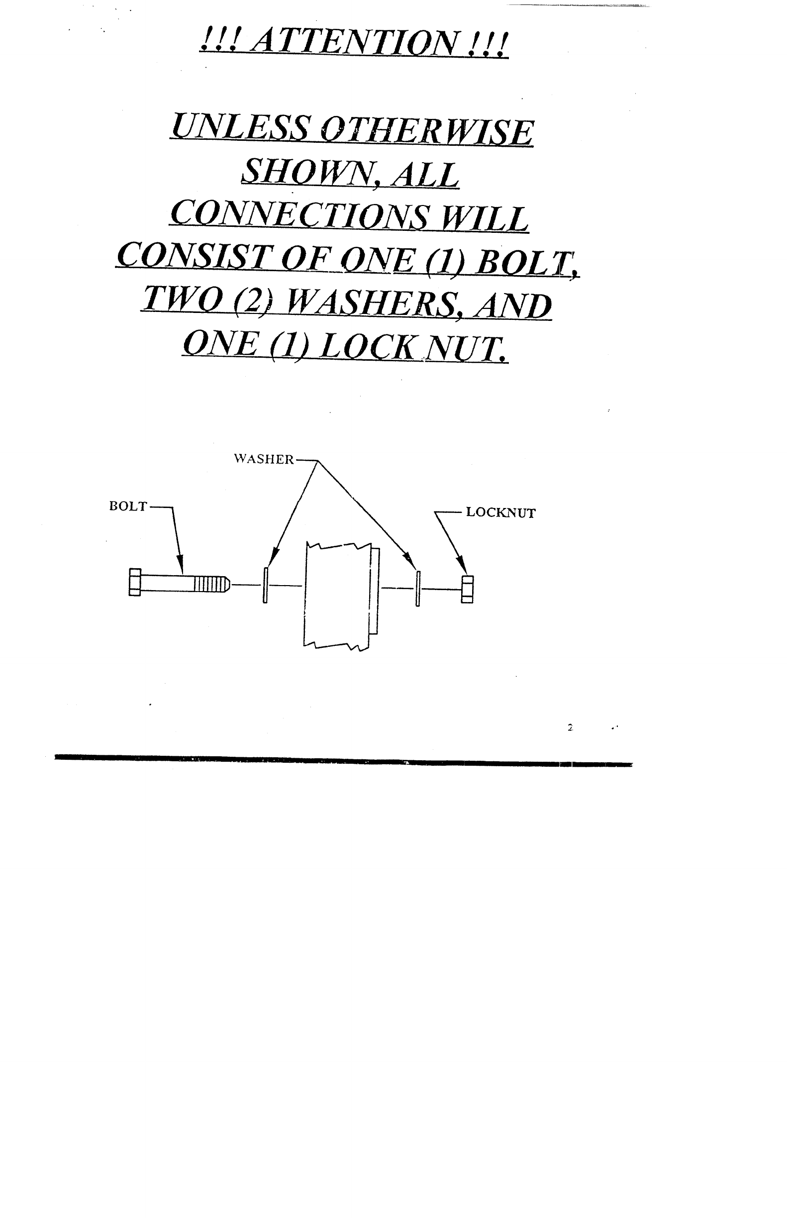
! ! ! ATTENTION ! ! !
UNLESS__O_T_HER~
C_~NNE~
_CAg_NSJS_T~F ONE LD BO_L Z’~
~HERS, AND
ONE (,O_LO~K..N_U_T,_
BOLT.
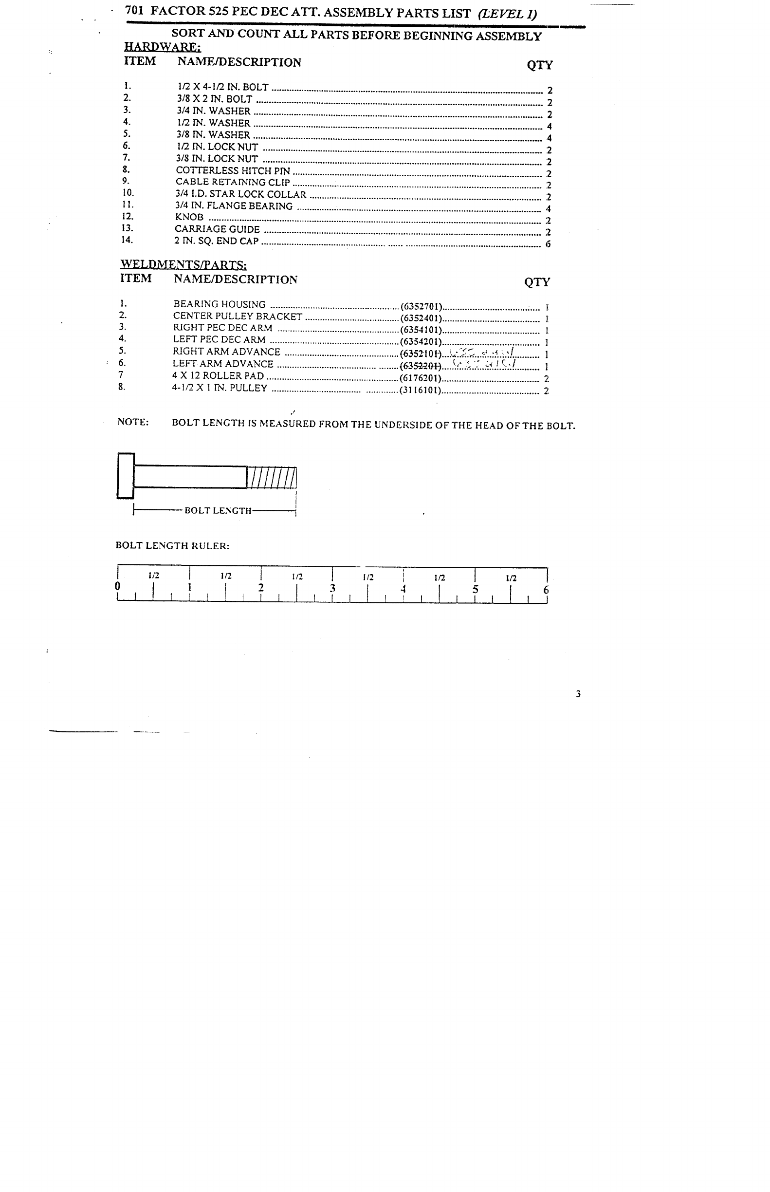
701 FACTOR 525 PEC DEC ATT. ASSEMBLY PARTS LIST (LEVEL 1)
SORT AND COI.£NT ALL PARTS BEFORE BEGINNING ASSEMBLY
ITEM
2.
3.
4.
5.
6.
7.
g.
9.
I0.
If.
12.
13.
14.
NAME/DESCRIPTION QTY
I/2 X 4-I/2 IN. BOLT ............................................................................................................
2
3/8 X 2 IN. BOLT ..................................................................................................................
2
3/4 IN. WASHER ....................................................................................................................
2
I/2 IN. WASHER ....................................................................................................................
4
3/8 IN. WASHER ..................................................................................................................
4
I/2 IN. LOCK NUT .....................................................................~ .........................................
2
3/8 IN. LOCK NUT ................................................................................................................
COTTER.LESS HITCH PIN ....................................................................................................
CABLE RETAINING CLIP ....................................................................................................
2
3/4 I.D. STAR LOCK COLLAR .............................................................................................
3/4 IN. FLANGE BEARING ..................................................................................................
4
KNOB .....................................................................................................................................
2
CARRIAGE GUIDE ...............................................................................................................
2
2 IN. SQ. END CAP ..............................................................................................................
6
WELDMENTS/PARTS:
ITEM NAME/DESCRIPTION QTY
2.
3.
4.
5.
6.
7
8.
BEARING HOUSING ....................................................
(6352701) ..................................
CENTER PULLEY BRACKET ...................................... (6352401) .......................................
KIGHT PEC DEC AILM ................................................. (6354101) ....................................... l
LEFT PEC DEC ARM .................................................... (6354201) ....................................... 1
RIGHT ARM ADVANCE - .
.............................................. (63~210 t’)....,.,..-.:.,<....:...:...: .............. 1
LEFT ARM ADVANCE ................................................ (635-2-20-I-)....}:.,:.).~:.).’...:~.~..!.~::.:. ......... 1
4 X 12 ROLLER PAD ..................................................... (6176201) ....................................... 2
4-t/2 X I IN. PULLEY ............................................. :...(3116101) ....................................... 2
NOTE: BOLT LENGTH IS MEASURED FROM THE UNDERSIDE OF THE HEAD OFTHE BOLT.
I////i//l
BOLT LENGTH
BOLT LENGTH RULER:
I/2 [ I/2
23
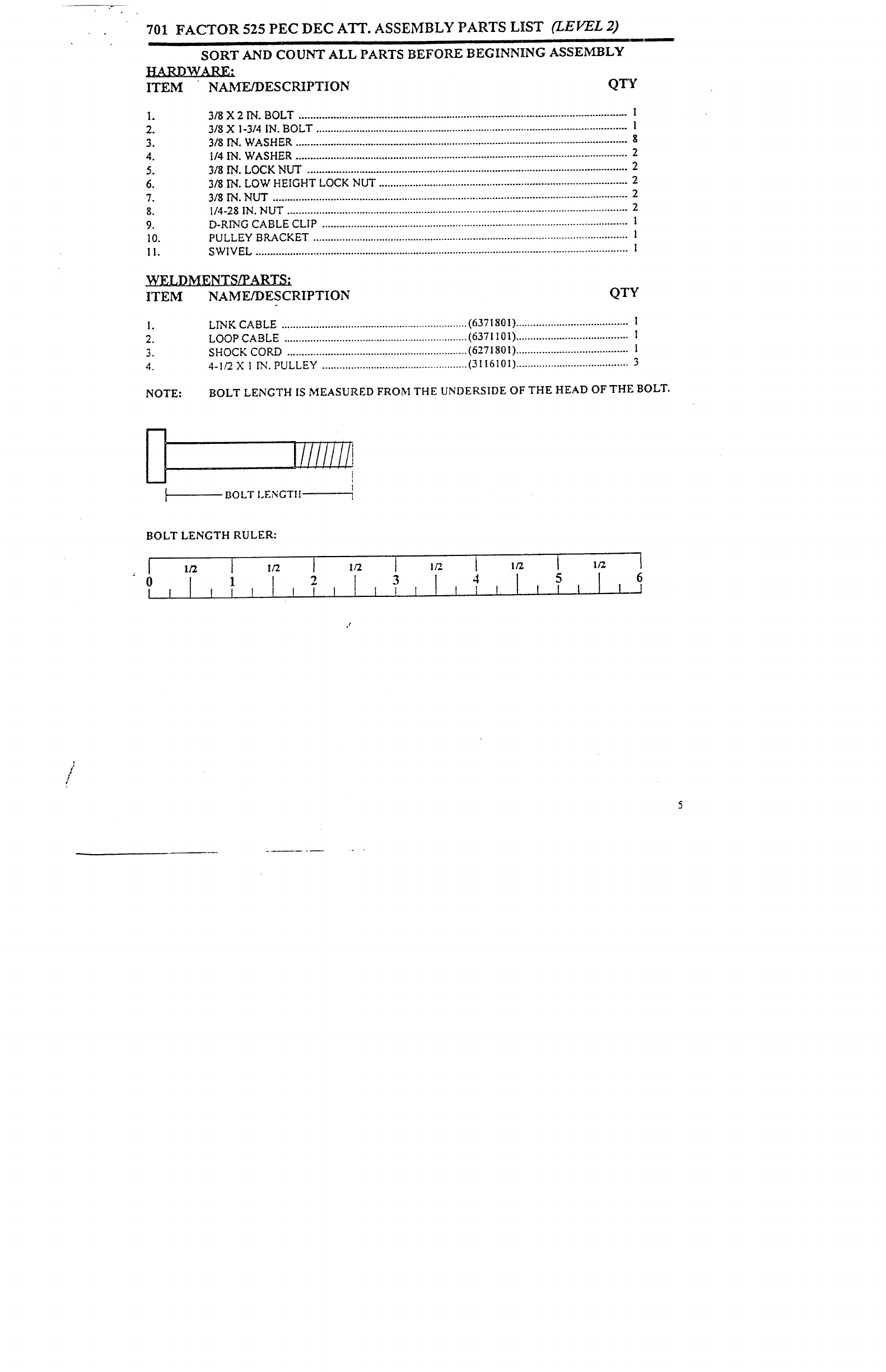
701 FACTOR 525 PEC DEC ATT. ASSEMBLY PARTS LIST (ZEVEL 2)
SORT AND COUNT ALL PARTS BEFORE BEGINNING ASSEMBLY
HARDWARE."
ITEM NAME/DESCRIPTION QTY
2.
3.
4.
5.
6.
7.
8.
9.
10.
II.
3/8 X 2 IN. BOLT .................................................................................................................. 1
3/8 X i-314 IN. BOLT ............................................................................................................. I
3/8 IN. WASHER ....................................................................................................................
1/4 IN. WASHER .................................................................................................................... 2
3/8 IN. LOCK NUT ................................................................................................................ 2
3/8 IN. LOW HEIGHT LOCK NUT ....................................................................................... 2
318 IN. NUT ............................................................................................................................ 2
t/4-25 IN. NUT ....................................................................................................................... 2
D-RING CABLE CLIP ........................................................................................................... l
PULLEY BRACKET .............................................................................................................. l
SWIVEL .................................................................................................................................. l
WELDMENTS/PARTS:
ITEM NAME/DESCRIPTION QTY
2.
3.
4.
LINK CABLE ................................................................. (6371801) ....................................... 1
LOOP CABLE ................................................................ (637I 101) .......................................
SHOCK CORD ............................................................... (6271801) .......................................
4-1/2 X 1 IN. PULLEY ................................................... (311610I) ....................................... 3
NOTE: BOLT LENGTH IS MEASURED FROM THE UNDERSIDE OF THE HEAD OF THE BOLT.
Iiiiiiii
BOLT LENGTIt
BOLT LENGTH RULER:
6
I._1
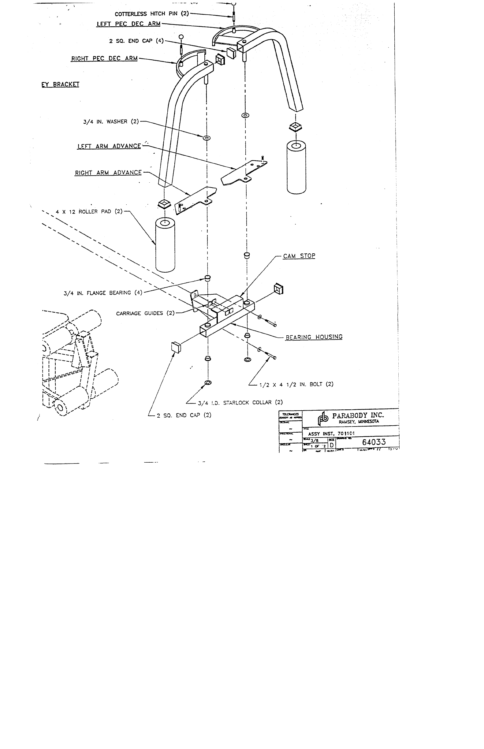
COTTERLE~ HITCH PIN
LEFT PEC DEC
2 SO. END CAP (4) 0
RIGHTPEC DEC ARM
I~Y BRACKET
3/4 IN. WASHER (2)
LEFT ARM A[
RIGHT ARM AE
"-. ~~/-- .CAM STOP
CARRIAGE GUIDES (2)
1
// .//
~/~~i/2 X 4 I/2 IN BOLT (2)
~, ,
// 3/4 LD. STAR~OCK COL~ (2)
~2 SQ. END C~ (2) ~ ~ P~BODY I~C-
~ AS~ INST. 70
~01
NOTE:
I0.
FACTOR 525 PEC DEC ATT. ASSEMBLY INSTRUCTIONS (LEVEL 1) ,--.
IF THE SHROUD IS ASSEMBLED TO THE FACTOR 525, IT WILL NEED TO BE REMOVED
TO ASSEMBLE THE PEC DEC A’vrACHMENT. PLEASE REMOVE THE SHROUD AT TH][S
TIME BY CAREFULLY REMOVING TIlE FOURTEEN (14) SHROUD FASTENERS.
Insert two (2) 2 IN. SQ. END CAPS into both ends of the BEARING HOUSING, as shown on drawing.
SECURELY assemble the BEARING HOUSING and the CENTER PULLEY BRACKET to the
FRONT UPRIGHT as shown on drawing, using two (2) I/2 X 4-I/2 IN. BOLTS, four (4) 1/2
WASHERS, and two (2) I/2 IN. LOCK NUTS. (THE CONNECTOR PLATES ON THE BEARING
HOUSING AND THE CENTER PULLEY BRACKET HAVE SLOTTED HOLES. SHIFT THE
BEARING HOUSING DOWN AND THE CENTER PULLEY BRACKET UP AS FAR AS
POSSIBLE)
Insert four (4) 2 IN. SQ. END CAPS into BOTH ENDS of the LEFT, and RIGHT PEC DEC ARMS
shown on drawing.
Assemble one (1) 314 IN: WASHER, and the LEFT ARM .ADVANCE to the LEFT PEC DEC ARM
shown on drawing. Also Assemble one (1) 3/4 IN. WASllEK, ".,qd the RIGHT ARM ADVANCE to the~
RIGHT PEC DEC ARM as shown.
Insert four (4) 3/4 IN. FLANGE BEARINGS into the BUSttlNGS of the BEARING ItOUSING,
shown on drawing.
Insert the LEFT and RIGHT PEC DEC ARMS through the 3/,4 IN. FLANGE BEARINGS in the
BEARING HOUSING on their respective sides as shown on dr’awing, ~d SECURE them in place with
two (2) 3/,4 I.D. STAR LOCK COL1.ARS.
Slide two (2) 4 X 12 ROLLER PADS onto the LEFT and RIGHT PEC DEC ARMS, until the
ROLLER PAD is FLUSH with the bottom of the ARMS. (IF A LUBRICANT IS REQUIRED, COAT
THE INSIDE OF THEROLI,ER PAl) WITll RUBIJINC ALCOIlOL. ALSO, ROTATING THE
PAD WHILE PUSHING UP WILL ilELP TO EASE ASSEMBLY)
Assemble two (2) KNOBS to two (2) COTTERLESS HITCH PINS as shown on drawing. Insert the
(2) COTTERLESS HITCH PINS through the BUSHINGS on th~ CAMS of the RIGHT and LEFT PEC
DEC AR51S, and into the holes on the PEC ARM ADVANCES. SEE DRAWING.
Attach two (2) CARRIAGE GUll)US ~o the CAB1 STOP o,i the BEARING ltOUSING where the
ARM ADVANCES makes contact with the CAM STOP.
LOOSELY assemble two (2) 4-1/2 X I IN. PULLEYS and two (2~ CABLE RETAINING CLIPS
CENTER PULLEY BRACKET as shown on dr-awing, using two (2) 3/8 X 2 IN. BOLTS, four (,~) 13/8
WASHERS, and two (2) 3/8 IN. LOCK NUTS. (NOTE: THIS CONNECTION WILL
TIGHTENED AFTER TI4E CABLE I tAS BEEN ROUrED)
THIS CONCLUDES THE ASSFMBLY OF (LEVEL 1)
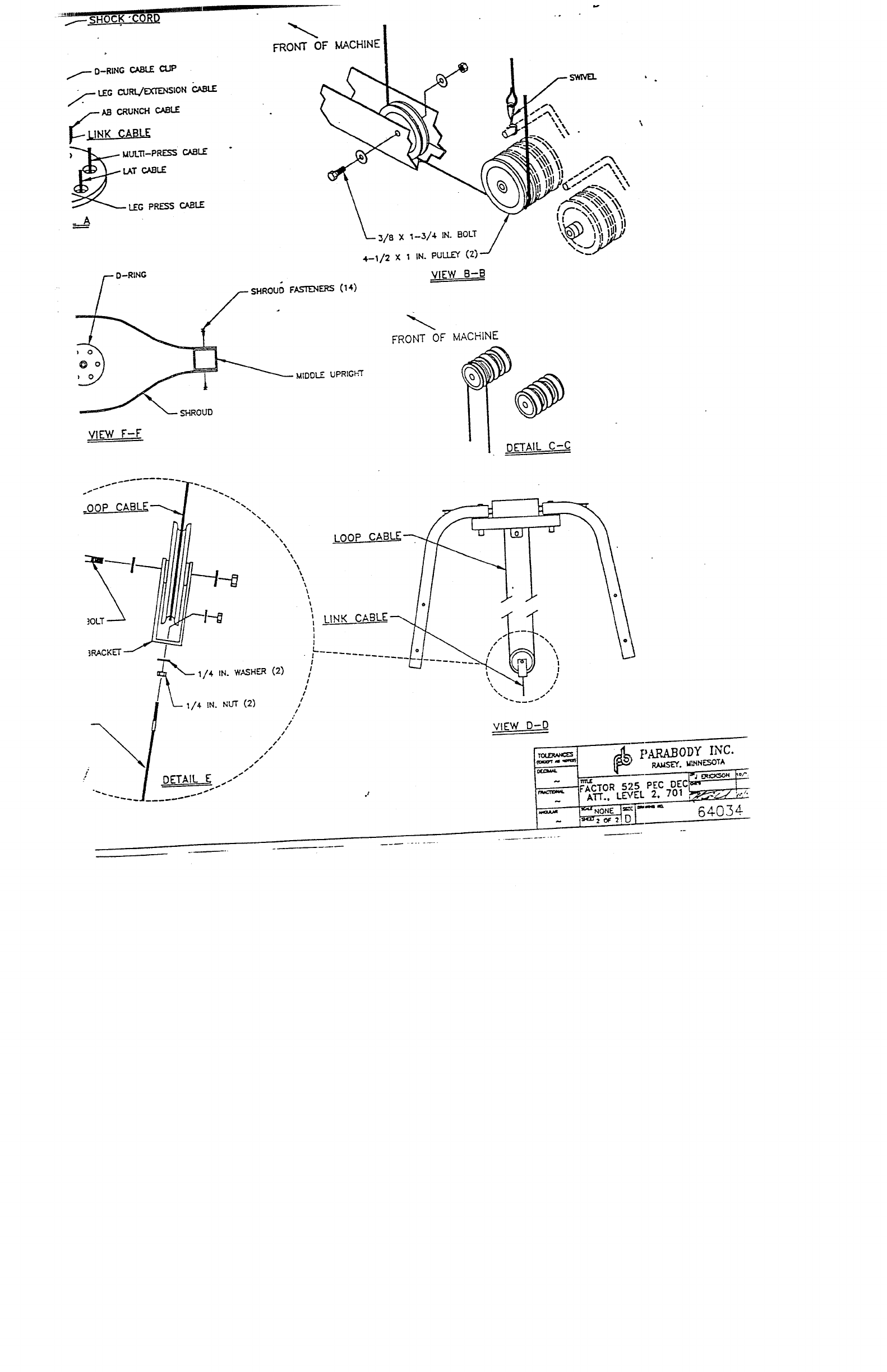
FACTOR 525 PEC DEC ATT. ASSEMBLY INSTRUCTIONS (LEVEL 2) --.
LOOSEN the 3/8 X 4 IN. BOLT that assembles the two (2) PULLEYS, and two (2) 1/2 IN. SPACEP,
the BASE directly behind the FRONT UPRIGHT. Remove the 3/$ IN. LOCK NUT, and the 3/g IN.
WASHER. Slide the BOLT out enough to remove the two (2) I/2 IN. SPACERS. Replace the 1/9- IN.
SPACERS with one (1) 4-I/2. X 1 IN. PULLEY, as shown in (VIEW B-B). Slide BOLT back
Replace the 3/8 IN. WASHER, and .3/8 IN. NUT. TIGHTEN CONNECTION SECURELY.
SECURELY assemble one (1) 4-1~ X 1 IN. PULLEY to the single hole in the BASE directly behind the
FRONT UPRIGHT as shown in (VIEW B-B) on drawing, using one (I) 3/8 X I-3/4 IN. BOLT, two
3/8 IN. WASHERS, and one (I)3/8 IN. LOCK NUT.
To assemble the LOOP CABLE, follow the cable routing diagram on drawing, and use the following
steps:
Assemble one end of the LOOP CABLE to the LEFT ARM ADVANCE and the other end ofthe
LOOP CABLE to the RIGHT ARM ADVANCE (MAKE SURE THAT LOOP CABLE IS
ROUTED BETWEEN THE AB CRUNCH CABLE AND THE FRONT UPRIGHT) as shown
on drawing, using~.wo (2) 3/8 IN. NUT, four (4) 3/8 IN. WAS’HERS, and two (2) 3/8 IN.
HEIGItT LOCK NUT. (TIGHTEN THE CONNECTION ENOUGH TO REMOVE THE
PLAY, YET ALLOWING THE LOOP TO MOVE FREELY)
¯Drape the CABLE over the both PULLEYS on the CENTER PULLEY BR.kCKET. (THIS
WILL FORM A LOOP IN THE CENTER OF THE CABLE)
¯Position CABLE RETAINING CLIPS in a 45 DEGREE position over the PULLEYS and
CABLES, and tighten the two (2) PULLEY connections SECURELY. SEE DRAWING.
To assemble the LINK CABLE, follow the cable routing diagram on drawing, and use the following steps:
¯LOOSELY assemble the PULLt"Y BRACKET to the LINK CABLE as shown in (DETAIL E)
drawing, using two (2) I/4 IN. WASHER, and two (2) t/4-2S IN. NUTS. (LOCATE PULLEY
BRACKET HALF WAY UP ON TIlE THREADS OF THE LINK CABLE. DO NOT
TIGHTEN NUTS AT TIllS TIME)
¯Slip one (I) 4-1/2 X I IN, PULLEY into the LOOP ofthe LOOP CABLE created from routing
STEP 3. (VIEW D-D) While holding that PULLEY in the LOOP, SECURELY assemble the
PULLEY BRACKET over the PULLEY as show~l in (DETAIL E) on drawing, using one (1) 3/~’,
2 IN. BOLT, two (2) 3;8 IN. WASI-IERS, and ot~e (I) 3~8 IN. LOCK
¯Route the LINK CABLE as shown on drawing. (ALSO SEE VIEW B-B)
¯Run the LINK CABLE through the pre-determined hole of:he D-RING as shown in (DETAIL A)
and attach one (1) D-RING CABLE CLIP around the ball end of the LINK CABLE.
Attach one (I) SHOCK CORD to the D-RING CABLE CLIP on the end ofthe LINK CABLE as shown
in (DETAIL A).
Route tile SHOCK CORD up and around the prc-determined 2 IN. PULLEY above the D-RING as shown
in (VIEW C-C). and down to tile BASE.
Atmch one (l) SWIVEL t° the end °fthe SHOCK CORD" Slipti:eendoftheSWIVEL°vertheL’P]N
on the BASE, and position the SWIVEL directl: over the FIRST PULLEY as shown in (VIEW B-B)
drawing.

701
NOTE:
lO.
FACTOR 525 PEC DEC ATT. ASSEMBLY INSTRUCTIONS (LEVEL
The D-RING CABLE CLIP on the end of the LINK CABLE should rcstjust above the D-RING. If the
LINK CABLE seems to be pulling on the D-RING or is resting too far above the D-RING, adjust it by
raising or lowering the two (2) 1/4-25 lN. NUTS that attaches the LINK CABLE to the PULLEY
BRACKET. When the correct height is obtained SECURELY tighten the two (2) 1/4-28 NUTS together
around the PULLEY BRACKET.
To adjust the pre-stretch on the PEC DEC AILVIS:
Pull up on the COT’fERLESS HITCH PIN.
Swivel the ARM forward or backward.
Let the PIN drop down into one ofthe two holes in the PEC ARM ADVANCES.
Or let the PIN drop behind the PEC ARM ADVANCES.
IF ASSEMBLING THE LEG PRESS ATTACHMENT NEXT, STOP HERE AND REFER TO
THOSE ASSEMBLY INSTRUCTIONS. IF ONLY ASSEMBLING TIIE PEC DEC ATTACHMENT
TO BASE UNIT, ~CONTINUE ON WITH THESE ASSEMBLY INSTRUCTIONS.
Wrap the SHROUD around the CABLES that t-oute to the D-RING, and assemble the SHROUD to
BOTH SIDES of the MIDDLE U,’~PRIGHT as shown in (VIEW F-F) on drawing, using the fourteen (14)
SHROUD FASTENERS.
THIS CONCLUDES THE ASSE~,IBLY OF (LEVEL 2), AND
THE ASSEMBLY OF THE PEC DEC ATTACHMENT FOR
THE FACTOR 525 BASE UNIT.
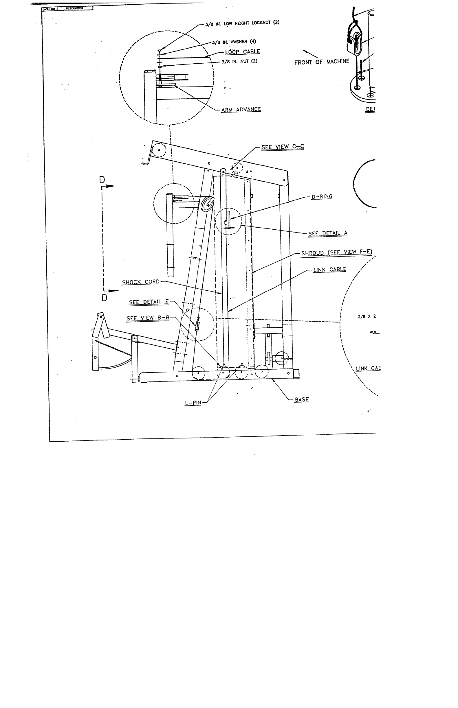
D
SHOCK CC
SEE D~I’AIL F--~
~EE VIEW C-C
o ;
L-PIN
FRONT OF I~,CHINE
SEE DET~,IL A
~SHROUD ...C~.SEE VIEW F-F)
/
f LIN.__~K_~ABLZ /
i
!
~--D-RING CABL~ CtJP
~ LEG CURL/~ION
lAB CRUNCH CABLE
._A
r- D-R~NG
~$HROUI~ FA_RI’ZNERS (I 4.)
~o MIDDLE U PRIGF,’r
~~ SHROUD
VIEW F-F
FRONT OF MACHINE
o
VIEW B~B
FRONT OF MACHINE
DETAIL C-C
VIEW D-D
FACTOR 525 PEC DEC~
