Paradox Security Systems MG6130 Wireless Console User Manual MAGELLAN MG 6160 MG 6160 Installation Manual
Paradox Security Systems Wireless Console MAGELLAN MG 6160 MG 6160 Installation Manual
Contents
- 1. User Manual 1
- 2. User Manual 2
- 3. User Manual 3
User Manual 1
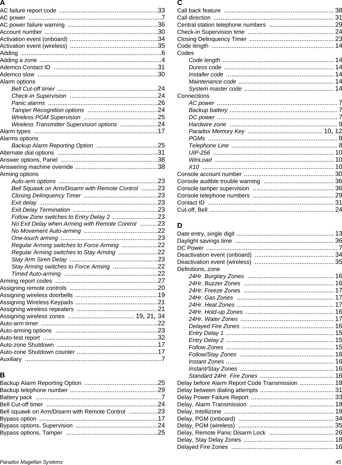
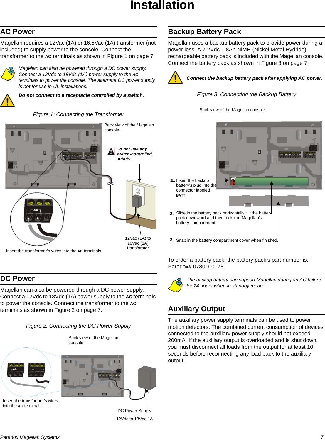
![Paradox Magellan Systems 3IntroductionAbout Magellan and this ManualMagellan is designed for fast and easy installation. Simply remove it from the box, mount the console and wireless transmitters, apply power, perform some basic programming and Magellan is ready to protect your home.Some of Magellan’s features can be programmed through a quick Installer menu (menu programming) or through section programming. Use the quick setup chapter (see page 4) to install the Magellan console quickly with the basic programming required for a standard security application. All other chapters (pages 7 to 38) are for advanced section programming. These other chapters provide more in-depth and precise information if more advanced programming is required.We recommend that you read this entire manual before you begin your installation.ConventionsSpecificationsPower input: AC*: 12Vac, 1A transformer or 16.5Vac, 1A transformerorDC: 12Vdc to 18Vdc (1A) power supplyorFor UL installations:Primary: 120Vac, 60Hz, 120mASecondary: 16.5Vac, 60Hz, 600mACurrentconsumption: 1A max. (600mA max. for UL installations)Auxiliary output: When using an AC or DC power source, the auxiliary output provides 13.8V (200mA maximum). To achieve this value, use a minimum of 15Vdc.Backup Battery: 7.2Vdc, 1.8Ah NiMH rechargeable battery pack (order # 0780100178)Not user replaceable. Replace battery every 3-5 years.PGM1: N.O solid-state relay (not polarized); Internal resistance 16 9max.; Max. handling current 100mA.PGM2: One low powered open-collector; Max. handling current 50mA.* It is recommended that you use a 12Vac, 1A transformer to power the Magellan console. The console will generate less heat when connected to a 12Vac transformer than when connected to a 16.5Vac transformer. In UL installations, use only the Universal transformer (model no. UB1640W, 16.5Vac, 40VA).The alternate DC power supply is not for use in UL installations.Grade A Household Fire and Burglar Alarm Warning System Unit.This symbol designates a reference to another section, manual or guide.This symbol designates either a warning or important information.This symbol designates a reminder or suggestion.[DATA] = - Text shown in this manner designates data or programming information that is entered through the console’s keypad.- Text shown in this manner can also designate a specific key that has to be pressed.](https://usermanual.wiki/Paradox-Security-Systems/MG6130.User-Manual-1/User-Guide-819069-Page-5.png)
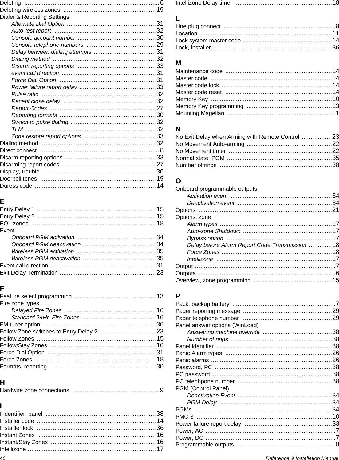
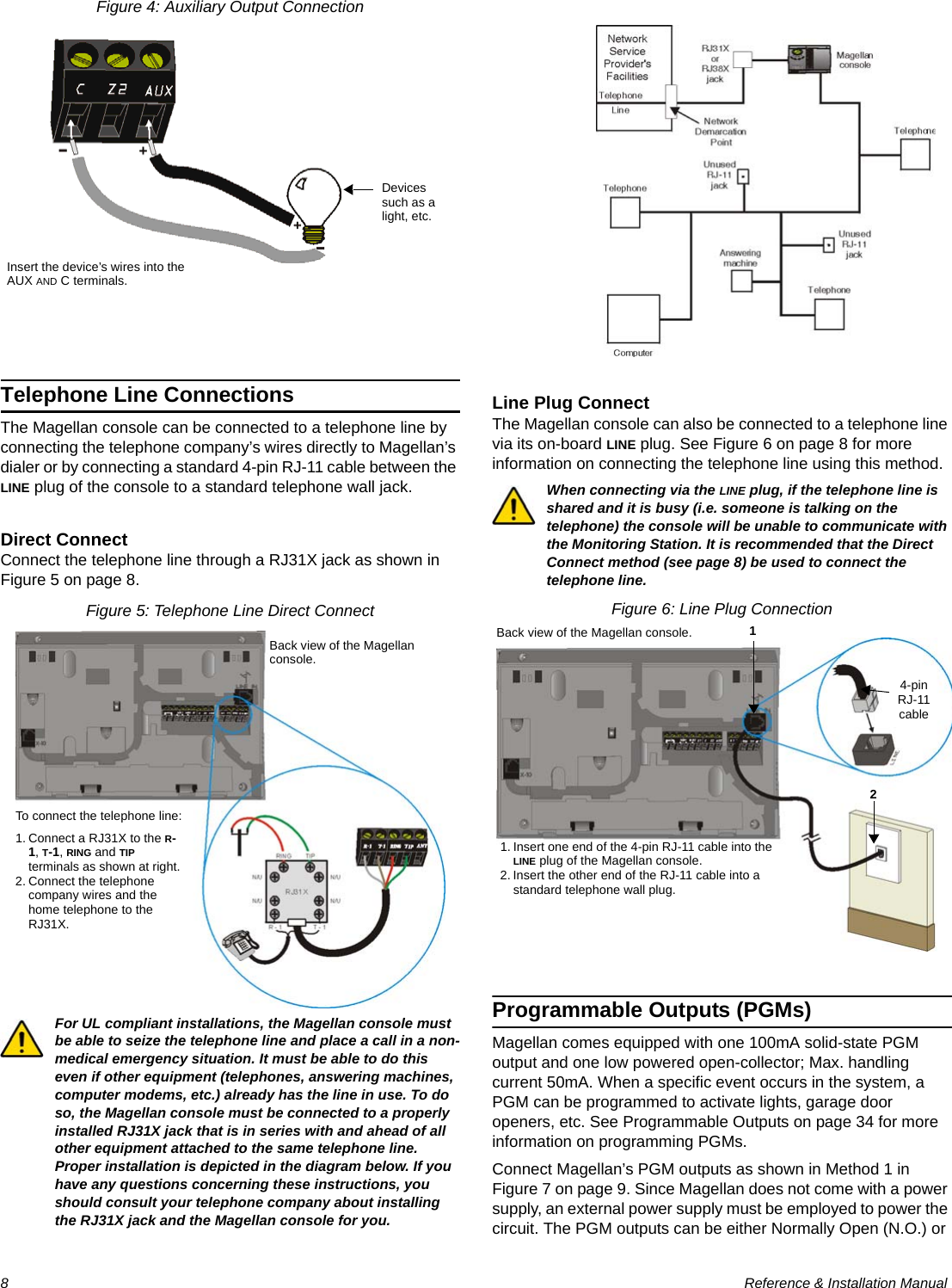
![4 Reference & Installation ManualQuick SetupFollow these steps to quickly set up Magellan with the required settings for a basic security installation.1.Getting Started1. After powering up for the first time, the language selection option will appear. Select the desired language.2. Press [START] to access the Installer menu.2.User Programming1. From the “User Profile” menu, press [OK].2. Select which user you wish to add by pressing [NEXT]. When the desired user appears, press [OK] and follow the menus to set:- Access code- User label- Remote controlWhen you are done the next menu option will appear (see Monitoring Station Reporting below).For more in-depth programming of the remote controls, see Programming the Remote Control’s Buttons on page 20.3.Monitoring Station Reporting1. From the “Communicator” menu, press [OK].2. Press [OK] and follow the menus to set:- Telephone numbers- Account Number - Report FormatWhen you are done the next menu option will appear. Press [NEXT] until you see the “Zone Profile” menu or press the [6] key to immediately access the “Zone Profile” menu.For more in-depth programming of the console’s communication features, see Reporting and Dialer Settings on page 27.4.Adding and Programming Zones1. From the “Zone Profile” menu, press [OK].2. Select which zone you wish to add by pressing [NEXT] and press [OK] when the desired zone number appears.3. Press the tamper switch on the transmitter you wish to assign to the selected zone. Follow the menus to set:- Zone Label- Zone Type- Other ZonesWhen you are done the next menu option will appear. Press [NEXT] until you see the “System Test” menu or press the [5] key to immediately access the “System Test” menu.For more in-depth programming of the console’s zones, see Zone Programming on page 15 and When hardwired zones are used, the EOL Resistor Option must be enabled for UL installations.Wireless Programming on page 18.5.Testing the Magellan System1. From the “System Test” menu, press [OK].2. Select which test you wish to perform by pressing [NEXT] and press [OK] when the desired test appears. The following tests can be performed:- Zone tests- Remote control tests- Reporting tests- Hardware tests](https://usermanual.wiki/Paradox-Security-Systems/MG6130.User-Manual-1/User-Guide-819069-Page-6.png)
![Paradox Magellan Systems 5WARNING! When testing the hardware, the speaker and sirens will also be tested. Avoid close proximity to the Magellan console when performing the hardware test to avoid any damage to your hearing.When you are done the next menu option will appear. Press [NEXT] until you see the “Passwords” menu or press the [8] key to immediately access the “Passwords” menu.6.Signal Strength1. From the “Signal Strength” menu, press [OK].2. The Magellan will begin testing the noise level and signal strength of all assigned wireless transmitters. Press [NEXT] to navigate through the various tests.Press [EXIT] when you are done.7.Passwords1. From the “Passwords” menu, press [OK].2. Select which password(s) or code(s) you wish to program by pressing [NEXT] and press [OK] when the desired password appears. The following passwords can be programmed:- Installer code- Maintenance code- Panel ID- PC PasswordWhen you are done the next menu option will appear. Press [EXIT].For more in-depth programming of the console’s passwords, see User Codes on page 14 and WinLoad Software Settings on page 38.8.Time and Date1. Press the [MENU] key.2. Press [NEXT] until you reach the “Time and Date” menu and press [OK] or press the [3] key to access the “Time and Date” menu.3. Select the time format (12Hr-clock or 24Hr-clock) and then program the time. Press [OK] when done.Program the date by entering the 4-digit year first, followed by the 2-digit month and then the 2-digit day. Press [OK] when done.Deleting Zones1. From the “Zone Profile” menu, press [OK].2. Select which zone you wish to delete by pressing [NEXT] and press [OK] when the desired zone number appears.3. Press [YES].4. Press [YES]. To delete another zone, press [YES] and then repeat steps 2 to 4.When you are done the next menu option will appear. Press [NEXT] until you see the “System Test” menu or press the [5] key to immediately access the “System Test” menu.For more in-depth programming of the console’s zones, see Zone Programming on page 15 and When hardwired zones are used, the EOL Resistor Option must be enabled for UL installations.Wireless Programming on page 18.](https://usermanual.wiki/Paradox-Security-Systems/MG6130.User-Manual-1/User-Guide-819069-Page-7.png)
![6 Reference & Installation ManualAdding Outputs1. From the “Output Profile” menu, press [OK].2. Select which output you wish to add, modify or delete by pressing [NEXT] and then [OK] when the desired output number appears.3. Select what type of output you wish to add. Press [YES] for a wireless output, or [NO] for a hardwired output. For hardwired, follow the menus to configure the output.4. If you are adding a wireless output, press the tamper switch on the transmitter you wish to assign to the selected zone. When you complete an output programming option, you will be given the choice to configure another output. If you do not choose to program another output, you will be brought back to the “Output Profile” menu.Deleting Outputs1. From the “Output Profile” menu, press [OK].2. Select which output you wish to delete by pressing [NEXT] and then [OK] when the desired output number appears.3. Press [YES].4. Press [YES]. To delete another output press [YES] and then repeat steps 2 to 4.When you are done the next menu option will appear. Press [NEXT] until you see the “System Test” menu or press the [5] key to immediately access the “System Test” menu.](https://usermanual.wiki/Paradox-Security-Systems/MG6130.User-Manual-1/User-Guide-819069-Page-8.png)
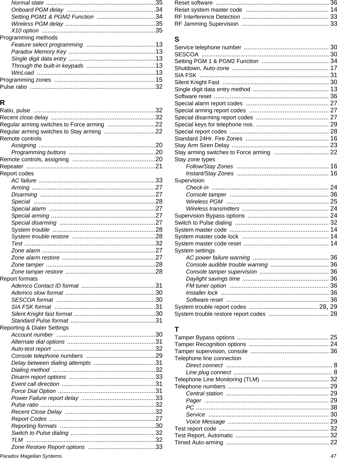
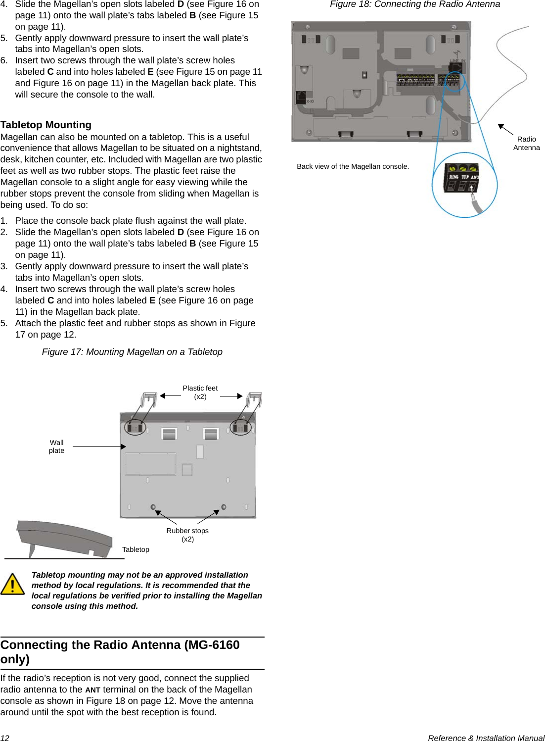
![Paradox Magellan Systems 9Normally Closed (N.C.) as detailed in PGM Normal State (Onboard Only) on page 35.If the current draw on the PGMs is to exceed 100mA, we recommend using an external relay as shown in Method 2 in Figure 7 on page 9. For connecting PGM2, see Figure 8.Using Method 2, connect the device to the output terminal of the external relay that matches the normal state of Magellan’s PGM output. For example, if PGM1’s normal state is Normally Open (N.O.), connect the device to the N.O. terminal of the external relay.Figure 7: PGM1 ConnectionsFigure 8: PGM2 ConnectionsHardwire Zone ConnectionsMagellan comes with two on-board hardwire zones. You can connect hardwire detection devices such as door contacts to Magellan’s zone terminals. Connect the detection devices as shown in Figure 9 on page 9. Please note the following:• Section [095] options [1] and [2] must be enabled in order to use the two on-board hardwire zones. See Zones 31 and 32 Become Hardwire Zones on page 18 for more information.• After connecting the detection devices, the zones must be defined. See Zone Programming on page 15 for more information.• The hardwire zones follow the console’s EOL and tamper definitions.Though any hardwire detection device can be connected to Magellan’s on-board hardwire zone inputs, it is recommended that only devices that do not require a power source (i.e., standard door contacts) be connected. Since Magellan has no power supply, an external power supply would have to be connected in order to power hardwire detection devices that do require a power source.Figure 9: Hardwire Zone ConnectionsExternal DC Power Supply Devices such as a light, etc.Devices such as a light, etc.External DC Power SupplyMethod 1(less than 50mA)Method 2(> 50mA)Back view of the Magellan console.External relayExternal DC Power Supply Devices such as a light, etc.Devices such as a light, etc.External DC Power SupplyMethod 1(less than 100mA)Method 2(exceeds 100mA)Back view of the Magellan console.External relay](https://usermanual.wiki/Paradox-Security-Systems/MG6130.User-Manual-1/User-Guide-819069-Page-11.png)
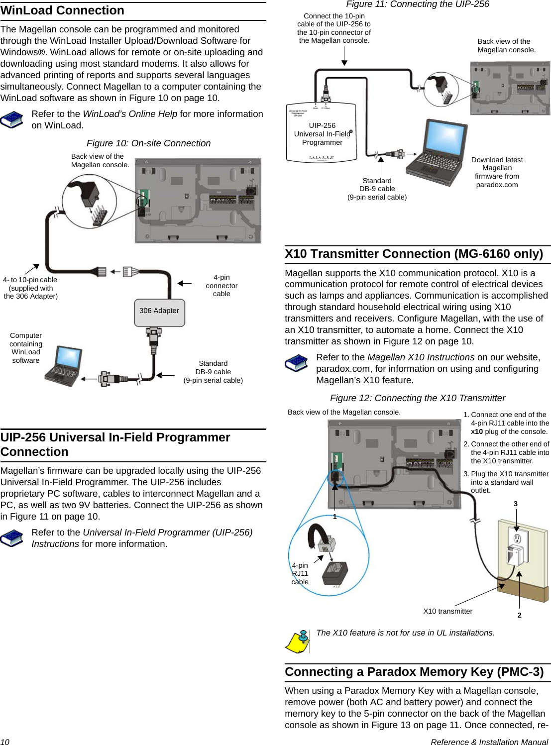
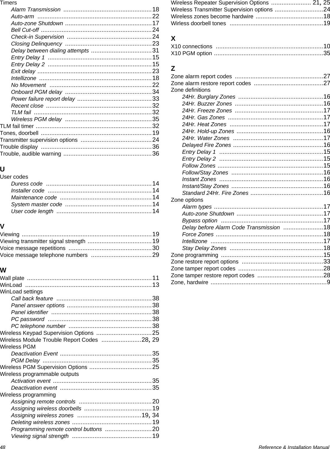
![Paradox Magellan Systems 13Programming MethodsWinLoad Installer Upload/Download SoftwareProgram the Magellan console remotely or on-site using the WinLoad Installer Upload/Download Software for Windows®. For more information, contact your local Paradox Distributor or visit our Web site at paradox.com. If you are using the WinLoad software, you must program the features explained on page 38.Please refer to WinLoad’s Online Help for more information on using WinLoad.Programming Using the Built-in KeypadUse the built-in keypad to access Magellan’s programming mode. Use the supplied Magellan Programming Guide to keep track of which sections were programmed and how. To access programming mode:1. Press and hold the [0] key.2. Enter your [INSTALLER CODE] or [MAINTENANCE CODE].3. Enter the 3-digit [SECTION] you wish to program.4. Enter the required [DATA].There are two methods that can be used to enter data when in programming mode: Single Digit Data Entry and Feature Select Programming.Single Digit Data Entry MethodAfter entering programming mode, some sections will require that you enter decimal values from 000 to 255. Other sections will require that you enter hexadecimal values from 0 to F. The required data will be clearly indicated in this manual as well as in the Magellan Programming Guide. When entering the final digit in a section, Magellan will automatically save and advance to the next section. Table 1 (see below) shows the keys and their equivalent decimal and/or hexadecimal value.Table 1: Decimal and Hexadecimal Values* CK = Center keypadFeature Select Programming MethodAfter entering certain sections, eight options will be displayed whereby each option from [1] to [8] represents a specific feature or option. To manipulate the options: • Press the key corresponding to the desired option and the option number will appear in the LCD display. This means the option is ON. Press the key again to remove the digit from the LCD display, thereby, turning OFF the option. • Press the [*] key to set all eight options to OFF. Press the keys until the current section’s options are set. When the options are set, press the [#] key to save and advance to the next section.• Press the [*] key twice to exit without changing any data.Programming Using a Paradox Memory KeyThe Paradox Memory Keys (PMC-3) are very useful when multiple Magellan consoles are to be programmed identically.Rather then programming each console by entering its programming mode and then scrolling through programming sections, use a memory key to program each console. The programming of a console with a memory key takes approximately three seconds.There are two actions that can be performed with a memory key.Download Data to Destination ConsoleTo download the data of a memory key into a console:1. Remove power from the Magellan console (AC and battery) and connect the memory key to the 5-pin connector on the left side of the back of the console (see Figure 13 on page 11).2. Re-apply both AC and battery power to the console.3. Press the [OK] key and Magellan will begin downloading the data from the memory key.Copy Data to Memory Key from Source ConsoleTo copy the contents of a console into the memory key.1. Remove power from the Magellan console (AC and battery) and connect the memory key to the 5-pin connector on the left side of the back of the console (see Figure 13 on page 11).2. Re-apply both AC and battery power to the console.3. Press the [NEXT] key and then the [OK] key. Magellan will begin copying its data into the memory key.The Installer code of the Magellan console used to download data to the memory key must be the same Installer code programmed in the Magellan console that is to download the contents from the same memory key. If the Installer codes do not match, the contents of the memory key cannot be downloaded into the receiving console.Example: The contents of the Magellan console A will be copied into memory key B. The Installer code for console A is 111111. In order to download the contents of memory key B into the Magellan console C, the Installer code programmed in console C must also be 111111.Key Value Key Value[1] 1[9] 9[2] 2[0] 0 (decimal)Space (Hexadecimal)[3] 3[1] CK*A (Hexadecimal only)[4] 4[2] CK*B (Hexadecimal only)[5] 5[3] CK*C (Hexadecimal only)[6] 6[4] CK*D (Hexadecimal only)[7] 7[5] CK*E (Hexadecimal only)[8] 8[6] CK*F (Hexadecimal only)](https://usermanual.wiki/Paradox-Security-Systems/MG6130.User-Manual-1/User-Guide-819069-Page-15.png)
![14 Reference & Installation ManualUser CodesA person must be assigned to a User code in order to have access to Magellan. A User code defines the extent of a user’s access to the system and consists of a code # (PIN) and user options. Magellan supports one Installer code, one Maintenance code and up to 16 User codes (one System Master code and 15 User codes).User Code LengthSection [090]: Option [1]Option [1] OFF = 6-digit User codesOption [1] ON = 4-digit User codes (default)All User codes can be set to lengths of either 4 or 6 digits. When the 4-digit option is selected, entering a 4-digit code will allow access. Using the 6-digit option, entering 6 digits is required to allow access.If the User code length is changed from 4 digits to 6 digits when User codes have already been programmed, the console will automatically add the last 2 digits by using the first 2 digits. For example, if the Access code is 1234 and you switch to 6 digits, the code will become 123412. Be sure to verify the Access codes after switching from 4-digit to 6-digit Access codes. When switching from 6 digits to 4 digits, the console will simply remove the final 2 digits of the Access code. For example, 123456 will become 1234.Installer CodeSection [181]; Default = 000000The Installer code is used to enter the console's programming mode (see Programming Using the Built-in Keypad on page 13), which allows you to program all the features, options and commands of the Magellan console. The Installer code can be 4 or 6 digits in length (see User Code Length on page 14) where each digit can be any value from 0 to 9. The Installer code cannot be used to program any User code. To change the Installer code:1. Access the installer programming mode (see page 13).2. Enter section [181].3. Enter a new [4- OR 6-DIGIT INSTALLER CODE].OR1. Press [MENU] + [4] + [INSTALLER CODE] + [8] + [NEW CODE].Maintenance CodeSection [182]; Default = 111111The Maintenance code is similar to the Installer code. It can be used to enter the console’s programming mode (see Programming Using the Built-in Keypad on page 13), which allows you to program all features, options and commands except for the console’s communication settings (sections [108] to [112] and [180] to [182]) as well as any User code. The Maintenance code can be 4 or 6 digits in length (see User Code Length on page 14). Each digit can be any value from 0 to 9.To change the Maintenance code:1. Access the installer programming mode (see page 13).2. Enter section [182].3. Enter a new [4- OR 6-DIGIT MAINTENANCE CODE].OR1. Press [MENU] + [4] + [INSTALLER CODE] + [8] + [NEW CODE].System Master CodeWith the System Master code a user can use any arming method and can program any user’s (from 1 to 16) Access code. The System Master code can be 4 or 6 digits in length (see User Code Length on page 14), where each digit can be any digit from 0 to 9. The System Master code cannot be changed by the Installer or Maintenance code, but it can be reset to default.Lock System Master CodeSection [090]: Option [3]Option [3] OFF = System Master code unlocked (default)Option [3] ON = System Master code lockedWith section [090] option [3] enabled, the System Master code can only be changed or deleted through WinLoad or a power down reset.Reset System Master CodeSection [200]Enter section [200] to reset the System Master code to default (1234/123456).Make sure that the Lock System Master Code feature (section [090] option [3]) is disabled.Duress CodeSection [090]: Option [4]Option [4] OFF = Duress code disabled (default)Option [4] ON = User code 016 becomes a Duress codeWith this feature enabled, User code 016 becomes a Duress code. When forced to arm or disarm their system, users can enter a Duress code (User code 016) to arm or disarm the system which can immediately transmit a silent alert to the Monitoring Station, transmitting the Duress report code programmed in section [148] (see page 28).Installer Code Used to program all console settings except User codes and remote controls.Maintenance Code Identical to the Installer code except that the code cannot program some communication settings.System Master CodeUser Code 001 Provides access to the following Magellan user features: language, voice and utility reporting, delays and tones, zone labels, system tests. Arm and disarm using any method as well as program User codes.15 User CodesUser Codes 002 to 016 Can arm and disarm the system.](https://usermanual.wiki/Paradox-Security-Systems/MG6130.User-Manual-1/User-Guide-819069-Page-16.png)
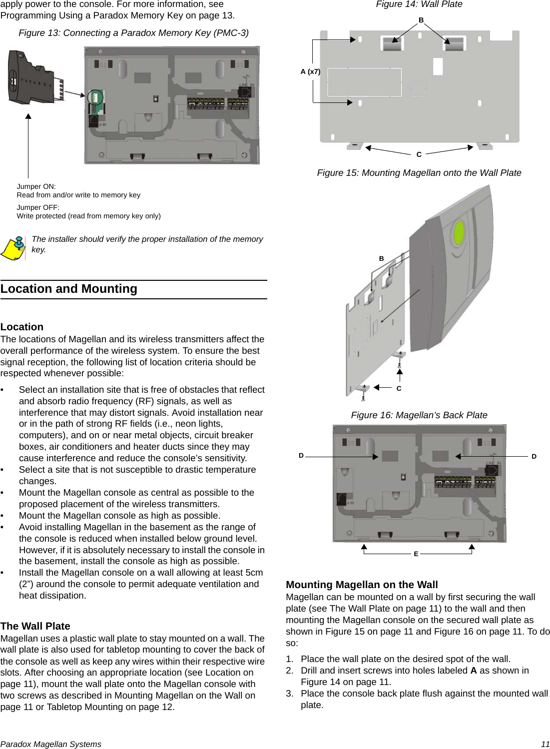
![Paradox Magellan Systems 15Zone ProgrammingMagellan supports up to 32 wireless zones whereby each zone can be configured with a different zone definition and option. Each zone can also have a voice label recorded for it. Magellan’s zones can be programmed using section programming or through the Installer menu.See Quick Setup on page 4 for more information on zone programming using the Installer menu.Zone Programming OverviewAfter assigning and setting up your wireless transmitters, define the associated zone's parameters. The zone parameters define the type of zone and how the control panel will react when an alarm condition occurs on that zone. These zone parameters are programmed into one section as detailed in Figure 19 on page 15.Figure 19: Magellan Zone Programming OverviewZone DefinitionsSections [001] to [032] represent zones 1 through 32 respectively, whereby the first three digits in each of these sections represents the zone's definition. To disable a zone, enter 000 and then press the [#] key. There are 15 available Zone Definitions, which are described as follows:Entry Delay 1Sections [001] to [032]: Zones 1 to 32, 3-digit # = 001When the system is armed and a zone defined with Entry Delay 1 opens, the console will generate an alarm after the programmed Entry Delay 1 Timer elapses. This is to provide users with enough time to enter the protected area and disarm the system. Entry Delay zones are commonly used at the entry/exit points of the protected area (i.e., front/back door, garage, etc.). Using different Entry Delays (see Entry Delay 2 below) is useful when, for example, one entry point requires a longer delay than another entry point.Entry Delay 1 TimerSection [060]: 001 to 255 seconds; 000 = Disabled; Default = 45 secondsEnter the desired 3-digit delay value from 000 to 255 seconds into section [060] to program the Entry Delay 1 Timer.Entry Delay 2Sections [001] to [032]: Zones 1 to 32, 3-digit # = 002Entry Delay 2 zones are identical to the Entry Delay 1 zones (see Entry Delay 1 on page 15), except it uses a separate Entry Delay Timer.Entry Delay 2 TimerSection [061]: 001 to 255 seconds; 000 = Disabled; Default = 45 secondsEnter the desired 3-digit delay value from 000 to 255 seconds into section [061] to program the Entry Delay 2 Timer.Follow ZonesSections [001] to [032]: Zones 1 to 32, 3-digit # = 003When an armed Follow zone opens, the console will immediately generate an alarm unless an Entry Delay zone opens first as described in the situations below:• If an armed Follow zone opens after an Entry Delay zone opens, the console waits until the Entry Delay Timer has elapsed before generating an alarm.• If an armed Follow zone opens after more than one Entry Delay zone opens, the console will wait until the Entry Delay Timer of the zone that opened first has elapsed.This feature is commonly used when a motion detector is protecting the area occupied by the entry point keypad. This will prevent the motion detector from causing an alarm when a user enters through the entry point to disarm the system.Press and hold the [0] keyEnter your [INSTALLER CODE] or [MAINTENANCE CODE]Enter 3-digit [SECTION][001] = Zone 1[002] = Zone 2[003] = Zone 3[004] = Zone 4[005] = Zone 5[006] = Zone 6[007] = Zone 7[008] = Zone 8[009] = Zone 9[010] = Zone 10[011] = Zone 11[012] = Zone 12[013] = Zone 13[014] = Zone 14[015] = Zone 15[016] = Zone 16[017] = Zone 17[018] = Zone 18[019] = Zone 19[020] = Zone 20[021] = Zone 21[022] = Zone 22[023] = Zone 23[024] = Zone 24[025] = Zone 25[026] = Zone 26[027] = Zone 27[028] = Zone 28[029] = Zone 29[030] = Zone 30[031] = Zone 31[032] = Zone 32Zone Definition000 = Zone disabled001 = Entry Delay 1002 = Entry Delay 2003 = Follow004 = Follow / Stay005 = Instant006 = Instant / Stay007 = Instant Fire008 = Delayed Fire Zone009 = 24Hr. Burglary010 = 24Hr. Hold-up011 = 24Hr. Buzzer012 = 24Hr. Gas013 = 24Hr. Heat014 = 24Hr. Water015 = 24Hr. FreezeZone Options*[1] = Auto-zone Shutdown (default)[2] = Zone Bypass (default)[3] = Future use[6] = Intellizone[7] = Delay alarm transmission[8] = Force Zone[4] [5] Zone Alarm TypeOFF OFF Audible alarm (steady)OFF ON Audible alarm (pulsed)ON OFF Silent alarmON ON Generate report onlyEnter 3-digit [ZONE DEFINITION]Use feature select method (p. 13) to select the [ZONE OPTIONS]Press the [#] key to saveKeypad beeps twice* Available through Section Programming only.](https://usermanual.wiki/Paradox-Security-Systems/MG6130.User-Manual-1/User-Guide-819069-Page-17.png)
![16 Reference & Installation ManualFollow/Stay ZonesSections [001] to [032]: Zones 1 to 32, 3-digit # = 004Follow/Stay zones function as follows:• All zones defined as Follow/Stay zones become Follow zones (refer to Follow Zones on page 15) when the Magellan system is Regular armed.• All zones defined as Follow/Stay zones become Stay zones when the Magellan system is Stay or Instant armed.Instant ZonesSections [001] to [032]: Zones 1 to 32, 3-digit # = 005When an armed Instant zone opens, the console immediately generates an alarm. Instant zones are commonly used for windows, patio doors, skylights and other perimeter type zones.Instant/Stay ZonesSections [001] to [032]: Zones 1 to 32, 3-digit # = 006Instant/Stay zones function as follows:• All zones defined as Instant/Stay zones become Instant zones (refer to Instant Zones on page 16) when the Magellan system is Regular armed.• All zones defined as Instant/Stay zones become Stay zones when the Magellan system is Stay or Instant armed.Standard 24Hr. Fire ZonesSections [001] to [032]: Zones 1 to 32, 3-digit # = 007Whenever a Standard 24Hr. Fire zone opens, whether it is armed or disarmed, the console will generate the following:• The console can send the corresponding Alarm Report Code from sections [131] to [138]. • Alarms are always audible regardless of other settings. Fire alarms generate an intermittent (pulsed) bell/siren output signal as shown in Figure 20 on page 16.Figure 20: Bell/Siren Output during a Fire AlarmDelayed Fire ZonesSections [001] to [032]: Zones 1 to 32, 3-digit # = 008When a Delayed 24Hr. Fire zone opens, whether it is armed or disarmed, the console will react as shown in Figure 21 on page 16. Delayed 24Hr. Fire zones are commonly used in residential homes where a smoke detector often generates false alarms (i.e., burning bread, etc.).This feature is not for use in UL installations.Figure 21: Delayed Fire Zone24Hr. Burglary ZonesSections [001] to [032]: Zones 1 to 32, 3-digit # = 009Whenever a 24Hr. Burglary zone opens, whether the system is armed or disarmed, the console will immediately generate an alarm.24Hr. Hold-up ZonesSections [001] to [032]: Zones 1 to 32, 3-digit # = 010When a 24Hr. Hold-up zone opens, whether it is armed or disarmed, the console will immediately generate an alarm. The SIA FSK reporting format includes specific report codes to identify the alarm as a Hold-up alarm (see Appendix 1: Automatic Report Code List on page 39).24Hr. Buzzer ZonesSections [001] to [032]: Zones 1 to 32, 3-digit # = 011This zone definition is particularly useful when a user wishes to be notified when something such as a safe or locker within the home has been accessed (i.e., a child accessing a valuable collection). This zone definition functions as follows: • Whenever a 24Hr. Buzzer zone opens, whether the console is armed or disarmed, the console sets off the keypad’s buzzer to indicate that the zone was breached. • The console will report the alarm, but will not enable the bell/siren output. • Enter any valid Access code on the keypad to stop the buzzer.](https://usermanual.wiki/Paradox-Security-Systems/MG6130.User-Manual-1/User-Guide-819069-Page-18.png)
![Paradox Magellan Systems 1724Hr. Gas ZonesSections [001] to [032]: Zones 1 to 32, 3-digit # = 012When a 24Hr. Gas zone opens, whether it is armed or disarmed, the console will immediately generate an alarm. The SIA FSK reporting format includes specific report codes to identify the alarm as a Gas alarm (see Appendix 1: Automatic Report Code List on page 39).24Hr. Heat ZonesSections [001] to [032]: Zones 1 to 32, 3-digit # = 013When a 24Hr. Heat zone opens, whether it is armed or disarmed, the console will immediately generate an alarm. The SIA FSK reporting format includes specific report codes to identify the alarm as a Heat alarm (see Appendix 1: Automatic Report Code List on page 39).24Hr. Water ZonesSections [001] to [032]: Zones 1 to 32, 3-digit # = 014When a 24Hr. Water zone opens, whether it is armed or disarmed, the console will immediately generate an alarm. The SIA FSK reporting format includes specific report codes to identify the alarm as a Water alarm (see Appendix 1: Automatic Report Code List on page 39).24Hr. Freeze ZonesSections [001] to [032]: Zones 1 to 32, 3-digit # = 015When a 24Hr. Freeze zone opens, whether it is armed or disarmed, the console will immediately generate an alarm. The SIA FSK reporting format includes specific report codes to identify the alarm as a Freeze alarm (see Appendix 1: Automatic Report Code List on page 39).Zone OptionsSections [001] to [032] represent zones 1 through 32 respectively as demonstrated in Figure 19 on page 15. After entering the 3-digit Zone Definition (see Zone Definitions on page 15), select one or more of the following Zone Options by using the Feature Select Programming Method (see page 13).Auto-zone ShutdownSections [001] to [032]: Zones 1 to 32; Option [1]Option [1] OFF = Auto-zone Shutdown disabledOption [1] ON = Auto-zone Shutdown enabled (default)If, in a single armed period, the number of alarms generated by a zone with the Auto-zone Shutdown option enabled exceeds the number defined by the Auto-zone Shutdown Counter, the console will no longer generate an alarm for that zone. The Auto-zone Shutdown Counter resets every time the system is armed.Auto-zone Shutdown CounterSection [067]: 001 to 015 alarms; 000 = Disabled; Default = 5 alarmsEnter the desired limit into section [067] to program the Auto-zone Shutdown Counter.Bypass OptionSection [001] to [032]: Zones 1 to 32; Option [2]Option [2] OFF = Bypass option disabledOption [2] ON = Selected zone is Bypass enabled (default)When a user uses the Bypass Programming feature, only zones with the Bypass option enabled can be programmed as bypassed.Fire zones cannot be programmed with the Bypass option because the console will not bypass a Fire zone.Alarm TypesSections [001] to [032]: Zones 1 to 32; Options [4] and [5]When an alarm condition occurs, the console can be programmed to react as shown in Table 2 on page 17.Table 2: Alarm Type OptionsThe Alarm Type options cannot be programmed for Fire zones. Fire zones are automatically programmed with an audible pulsed alarm. This cannot be altered.IntellizoneSections [001] to [032]: Zones 1 to 32; option [6]Option [6] OFF = Intellizone disabled (default)Option [6] ON = Intellizone enabledThis feature reduces the possibility of false alarms. When a zone with the Intellizone option opens, the console does not immediately generate an alarm. First it triggers the Intellizone Delay Timer. If any of the following conditions occur during this period, the panel will generate an alarm:Options Description[4] [5]OFF OFF Audible steady alarm (default)When the conditions for an alarm have been met, the control panel can transmit the appropriate Zone Alarm report code (see page 27) and provides a steady output for the on-board siren.OFF ON Audible pulsed alarmWhen the conditions for an alarm have been met, Magellan can transmit the appropriate Zone Alarm report code (see page 27) and provides a pulsed output (see Figure 20 on page 16) for the on-board siren.ON OFF Silent alarmWhen the conditions for an alarm are met, the control panel can transmit the appropriate Zone Alarm report code (see page 27) and will not activate the control panel’s bell output. The appropriate ARM or STATUS LED on the keypads will flash to indicate an alarm and the user will still have to disarm the system.ON ON Report onlyWhen the conditions for an alarm have been met, the control panel can transmit the appropriate Zone Alarm report code (see page 27). The system will not have to be disarmed.](https://usermanual.wiki/Paradox-Security-Systems/MG6130.User-Manual-1/User-Guide-819069-Page-19.png)
![18 Reference & Installation Manual• During the Intellizone Delay, a second zone has caused an alarm.• During the Intellizone Delay, the zone in alarm has restored (closed) and re-occurred (opened).• The zone in alarm is still open after the Intellizone Delay has elapsed.This feature is not for use in UL installations.Intellizone Delay TimerSection [065]: 010 to 255 seconds; Default = 45 secondsEnter the desired 3-digit value into section [065] to program the Intellizone Delay Timer.Delay Before Alarm Report Code TransmissionSections [001] to [032]: Zones 1 to 32; option [7]Option [7] OFF = Delay alarm transmission disabled (default)Option [7] ON = Delay alarm transmission enabledThis feature is commonly used with Entry Delay zones to reduce false alarms created by new users who may not disarm the system in time. This feature works as follows: • When an alarm condition occurs on a zone with this option enabled, the console enables the bell/siren output, but does not report the alarm to the monitoring station until the end of the Alarm Transmission Delay. • During this period, disarming the system disables the bell/siren output and cancels the report code transmission. This feature is not for use in UL installations.Alarm Transmission DelaySection [075]: 001 to 255 seconds; 000 = Disabled; Default = 0 secondsEnter the desired 3-digit delay value into section [075] to program the Alarm Transmission Delay.Force ZonesSections [001] to [032]: Zones 1 to 32; Option [8]Option [8] OFF = Force zone disabledOption [8] ON = Selected zone is Force enabled (default)Any open Force zones at the time of arming will be considered deactivated by the console. If during this period a deactivated zone is closed, the console will revert that zone to active status. Consequently, the console will generate an alarm if the zone is breached.Fire zones cannot be programmed with the Force zone option because the console will not bypass a Fire zone when the system is being Force armed.This feature is not for use in UL installations.Stay Delay ZonesSection [094]: Options [1]Option [1] OFF = Stay Delay zone disabled (default)Option [1] ON = Stay Delay zone enabledWhen a Follow/Stay or Instant/Stay zone is armed using the Stay or Instant arming methods, with this option enabled and the zone is triggered, an alarm will not generate until the programmed Stay Delay elapses. A zone defined as Stay Delay follows the Entry Delay 1 Timer. To program the Entry Delay Timers, refer to Entry Delay 1 on page 15. This feature is not for use in UL installations.Zones 31 and 32 Become Hardwire ZonesSection [095]: Options [1] and [2]Option [1] OFF = Wireless zone 31 remains unchanged (default)Option [1] ON = Wireless zone 31 uses the on-board hardwire zone input 1Option [2] OFF = Wireless zone 32 remains unchanged (default)Option [2] ON = Wireless zone 32 uses the on-board hardwire zone input 2The Magellan console comes with two on-board zone inputs, hardwire zone inputs 1 and 2. Section [095] options [1] and [2] allow you to convert zones 31 and 32 from wireless to hardwire by allowing you to connect hardwire detection devices (i.e., door contacts) to zone inputs 1 and 2.• With section [095] option [1] ON, zone 31 is connected to zone input 1. • With section [095] option [2] ON, zone 32 is connected to zone input 2.EOL (End-Of-Line) ZonesSection [095]: Option [3]Option [3] OFF = Hardwire zones 1 & 2 do not require EOL resistors (default)Option [3] ON = Hardwire zones 1 & 2 require EOL resistorsThis feature only applies to Magellan’s on-board zone inputs. Section [095] options [1] and/or [2] (see Zones 31 and 32 Become Hardwire Zones on page 18) must be ON in order to use this feature.If the hardwire detection devices connected to Magellan’s zone inputs 1 and 2 have input terminals that require 1K9 end-of-line resistors, enable (ON) section [095] option [3]. For details on using EOL resistors, refer to page 9.When hardwired zones are used, the EOL Resistor Option must be enabled for UL installations.Wireless ProgrammingThe Magellan system supports up to 32 wireless zones and two wireless doorbells. These wireless zones are monitored using transmitters such as wireless detectors and door contacts. The Magellan console only supports the Paradox Magellan series of wireless transmitters. The programming of the transmitters is accomplished in two steps:1. Assign the wireless transmitter to Magellan.2. Program the wireless zone.](https://usermanual.wiki/Paradox-Security-Systems/MG6130.User-Manual-1/User-Guide-819069-Page-20.png)
![Paradox Magellan Systems 19Assigning Wireless Zone TransmittersSections [201] to [232]: Zones 1-32; Wireless Transmitters 1-32Sections [201] to [232] represent zones 1 to 32. A wireless transmitter assigned to a section ([201] to [232]) will be assigned to the zone represented by the section.For example, a wireless transmitter assigned to section [205] will be assigned to zone 5. To assign a wireless transmitter:1. Access the installer programming mode (see page 13).2. Enter the [SECTION] corresponding to the desired zone.3. Enter the 6-digit [SERIAL NUMBER] of the wireless transmitter.The serial number is located on the inside of the wireless transmitter.The wireless transmitters must be activated once having been assigned to the Magellan console. To activate a transmitter, insert the batteries and close the cover. To ensure proper synchronization between the console and the transmitter, open and close the zone corresponding to the transmitter.Are the zones that have wireless transmitters assigned to them programmed? See Zone Definitions on page 15 and Zone Options on page 17.Wireless transmitters can also be assigned through the Installer menu. Press [MENU] + [4] + [INSTALLER CODE] + [6]. Select the zone you wish to assign the transmitter to, press [OK], open the cover of the transmitter and then close the cover. The transmitter has been assigned. Refer to the Magellan Quick Setup on page 4 for more information on the Installer menu and the assignment of the wireless transmitters.Assigning Wireless Doorbells to the ConsoleSections [233] and [234]: Wireless Doorbells 1 and 2Magellan supports the use of two wireless doorbells. By connecting a pushbutton to the Universal Transmitter inputs of a Magellan Wireless Door Contact (MG-DCT1 or MG-DCTXP2), the MG-DCT1/MG-DCTXP2 will transmit a signal to Magellan whenever the pushbutton is pressed. Magellan will in turn become a doorbell and play a predetermined tone (see Wireless Doorbell Tones on page 19).Please refer to the appropriate Magellan Wireless Door Contact Instruction for information on the installation and configuration of the wireless door contact.To assign a wireless doorbell:1. Access the installer programming mode (see page 13).2. Enter the [SECTION] corresponding to the desired doorbell.3. Enter the 6-digit [SERIAL NUMBER] of the MG-DCT1.Wireless Doorbell TonesSection [096]: Options [1] to [4]Options [1] and [2] = Set tone for wireless doorbell 1Options [3] and [4] = Set tone for wireless doorbell 2Section [096] options [1] to [4] set the tones that will be played when Magellan receives a signal from either wireless doorbell 1 or 2 or both. Magellan comes with four tones. Refer to Table 3 on page 19 to set the desired tone.Table 3: Wireless Doorbell TonesDeleting Assigned Wireless TransmittersSections [201] to [232]: Zones 1-32; Wireless Transmitters 1-32Sections [233] and [234]: Wireless Doorbells 1 and 2To delete an assigned wireless transmitter:1. Access the installer programming mode (see page 13).2. Enter the [SECTION] corresponding to the desired zone or doorbell.3. Press the [0] key six times to clear the wireless transmitter’s serial number.Viewing Wireless Transmitter Signal StrengthSections [201] to [232]: Zones 1-32; Wireless Transmitters 1-32Once wireless transmitters have been assigned to the Magellan console, the signal strength of each transmitter can be verified in sections [201] to [232] (zones 1 to 32 respectively). Each section represents the signal strength viewer for the wireless transmitter assigned to the corresponding zone. For example, section [201] is the viewer for the wireless transmitter assigned to zone 1 and section [232] is the viewer for the wireless transmitter assigned to zone 32. The signal strength is displayed using two terms:• “Good”: This is an average reading and is acceptable.• “Weak”: This is the weakest reading. The transmitter should be moved to another location. Sometimes moving the transmitter by a small amount will greatly increase the signal reception.To view the signal strength of a wireless transmitter:1. Access the installer programming mode (see page 13).2. Enter the [SECTION] corresponding to the desired zone or doorbell.3. The LCD will display either “Good” or “Weak” on the screen.When performing a signal strength test, Magellan also displays the noise level surrounding each of the transmitters. “Low” refers to a low level of noise while “High” refers to a noisy environment.Section [096] - Options [1] and [2] Doorbell Tone #Option [1] OFF / Option [2] OFF (Doorbell 1) Tone 1 (default)Option [1] OFF / Option [2] ON (Doorbell 1) Tone 2Option [1] ON / Option [2] OFF (Doorbell 1) Tone 3Option [1] ON / Option [2] ON (Doorbell 1) Tone 4Section [096] - Options [3] and [4] Doorbell Tone #Option [3] OFF / Option [4] OFF (Doorbell 2) Tone 1Option [3] OFF / Option [4] ON (Doorbell 2) Tone 2 (default)Option [3] ON / Option [4] OFF (Doorbell 2) Tone 3Option [3] ON / Option [4] ON (Doorbell 2) Tone 4](https://usermanual.wiki/Paradox-Security-Systems/MG6130.User-Manual-1/User-Guide-819069-Page-21.png)
![20 Reference & Installation ManualThe signal strength can also be verified by performing a system test. See Quick Setup on page 4 for more information.Assigning Remote ControlsThe Magellan console accepts up to 16 fully programmable remote controls. Every User code can have one remote control assigned to it.To assign a remote control:1. Press [MENU] + [4] + [2].Programming the Remote Control’s ButtonsSections [041] to [056]: Users 1 to 16; Remote Controls 1 to 16Sections [041] to [056] represent the remote controls assigned to User codes 1 to 16 (see table below).The remote control will transmit a signal for only 1 second when a button is pressed and held for 1 second. This is done to conserve the remote control’s batteries.Although remote controls can be assigned by the System Master, the remote control’s buttons are programmed by the installer.Each remote control can be programmed to perform different actions. Each digit in sections [041] to [056] represents a button or combination of buttons (see table below).To program a remote control’s buttons:1. Access the installer programming mode (see page 13).2. Enter the [SECTION] (sections [041] to [056]) corresponding to the desired remote control.3. Enter the [HEXADECIMAL VALUE] (0 to F) of the desired button option from the Button Options Table on page 23.If you do not wish to program all the buttons or button combinations, press the [#] key at any time to save and exit.If you enable any Panic button options, you must enable the Panic options in the control panel (refer to Panic Alarms on page 26).Programming the MG-REM1/MG-REM2Warning: When section [040] is accessed, the console will copy the saved value of that section to all remotes.Section RC# Data (Default: 4DE0) Section RC# Data (Default: 4DE0) [040]Default 1-16 ______ ______ ______ ______[041] 1 ______ ______ ______ ______ [049] 9 ______ ______ ______ ______[042] 2 ______ ______ ______ ______ [050] 10 ______ ______ ______ ______[043] 3 ______ ______ ______ ______ [051] 11 ______ ______ ______ ______[044] 4 ______ ______ ______ ______ [052] 12 ______ ______ ______ ______[045] 5 ______ ______ ______ ______ [053] 13 ______ ______ ______ ______[046] 6 ______ ______ ______ ______ [054] 14 ______ ______ ______ ______[047] 7 ______ ______ ______ ______ [055] 15 ______ ______ ______ ______[048] 8 ______ ______ ______ ______ [056] 16 ______ ______ ______ ______++++](https://usermanual.wiki/Paradox-Security-Systems/MG6130.User-Manual-1/User-Guide-819069-Page-22.png)
![Paradox Magellan Systems 21 The button of the MG-REM1 and MG-REM2 remote controls has been permanently programmed to disarm the system. However, when the system is disarmed and the Magellan console’s radio is on (MG-6160 only), the button can be used for volume control. The button’s functionality cannot be altered. The button of the MG-REM2 remote control has been permanently programmed to request feedback from the system. The button’s functionality cannot be altered. The , and button combinations do not function with the MG-REM1 remote control. The , and button combinations do not function with the MG-REM2 remote control.When section [040] is accessed, the console will display the contents of section [041] and copy the saved value of that section to all remote options: [041] to [56].Assigning Wireless KeypadsSections [243] to [246]: Keypads 1-4Sections [243] to [246] represent keypads 1 to 4. To assign a wireless keypad:1. Access the installer programming mode (see page 13).2. Enter the [SECTION] corresponding to the desired keypad.3. Enter the 6-digit [SERIAL NUMBER] of the wireless keypad.Assigning Wireless RepeatersSections [247] to [248]: Repeater 1-2Sections [247] to [248] represent repeater 1 and 2. To assign a wireless repeater:1. Access the installer programming mode (see page 13).2. Enter the [SECTION] corresponding to the desired repeater.3. Enter the 6-digit [SERIAL NUMBER] of the wireless repeater.Wireless Repeater OptionsSection [300] to [305]:Options [1] to [8]; Repe ater 1 opti ons Section [306] to [311]:Options [1] to [8]; Repeater 2 options Defaults = OFFSections [300] to [303] represent zone repeating options for Repeater 1. Section [304] represents PGM repeating options for Repeater 1. Section [305] represents wireless keypad and doorbell repeating options. Sections [306] to [309] represent zone repeating options for Repeater 1. Section [310] represents PGM repeating options for Repeater 1. Section [311] represents wireless keypad and doorbell repeating options. By default, each option is OFF. Enable the option to have the respective zone/PGM/wireless keypad/doorbell repeated.Button Options Table0 - Button disabled1 - Regular arming2 - Stay arming3 - Instant arming4 - Force arming5 - N/A6 - N/A7 - N/A8 - Panic 1†9 - Panic 2†A* - Panic 3†B* - PGM Activation (Event Group #7, see Appendix 1: PGM Event Table)C* - PGM Activation (Event Group #8, see Appendix 1: PGM Event Table)D* - Turn FM radio ON/OFF (MG-6160 only)E* - FM radio memory scan (MG-6160 only)F* - Non-medical alarm* = Hex values A to F are keys [1] to [6] from Magellan’s Center Keypad. Refer to Figure 1 on page 2.† = The panic feature (section [091] options [1] to [3]) must be enabled. MG-REM1 MG-REM2+ + ++ + +](https://usermanual.wiki/Paradox-Security-Systems/MG6130.User-Manual-1/User-Guide-819069-Page-23.png)
![22 Reference & Installation ManualArming and DisarmingRegular Arming Switches to Stay ArmingSection [092]: Option [4]Option [4] OFF = Regular arming switches to Stay arming disabled (default)Option [4] ON = Regular arming switches to Stay arming enabledIf a user Regular arms the system, but does not exit through (open and close) an Entry Delay zone during the Exit Delay, the console can be programmed to switch from Regular arming to Stay arming.Regular Arming Switches to Force ArmingSection [092]: Option [5]Option [5] OFF = Regular arming switches to Force arming disabledOption [5] ON = Regular arming switches to Force arming enabled (default)With this feature enabled, the console will always Force arm instead of Regular arm when a valid User code is entered. In installations where the user must always Force arm when leaving the protected area, this feature allows users to Force arm after entering their User code.This feature is not for use in UL installations.Stay Arming Switches to Force ArmingSection [092]: Option [6]Option [6] OFF = Stay Arming Switches to Force Arming disabled (default)Option [6] ON = Stay Arming Switches to Force Arming enabledWith this feature enabled, the console will always Force arm and Stay arm when a valid User code is entered even if there are perimeter zones open.This feature is not for use in UL installations.Timed Auto-ArmingSection [092]: Option [1]Option [1] OFF = Timed Auto-arming disabled (default)Option [1] ON = Timed Auto-arming enabledThe Magellan system can be programmed to arm every day at the time specified by the Auto-arm Timer (see Auto-arm Timer on page 22). The following also apply:• The Auto-arming options (see Auto-Arming Options on page 23) determine the arming method. • Any open zones detected when the system is Auto-armed will be bypassed regardless of their definition (except 24Hr. zones). • The console will enter a 60-second Exit Delay period before arming the system. At this point, Auto-arming can be cancelled by entering a valid Access code. • Once the system has successfully armed, the console can transmit the Timed Auto-Arming report code programmed in section [124]. Example: To automatically arm the system everyday at 6:15PM, enable section [092] option [1] to activate Timed Auto-arming and then key in 18:15 into section [085].This feature is not for use in UL installations.Auto-arm TimerSection [085]Using the 24-hour clock (i.e., 6:30PM = 18:30), program the time that you wish the console to attempt to arm the system and/or send the Late to Close report code.No Movement Auto-ArmingSection [092]: Option [2]Option [2] OFF = No Movement Auto-arming disabled (default)Option [2] ON = No Movement Auto-arming enabledIf no movement occurs in a zone's protected area for the period specified by the No Movement Timer (see below), the console can automatically arm the system.• The Auto-arming option (see Auto-Arming Options on page 23) determines the system's arming method. • Any open zones detected when the system is Auto-armed will be bypassed regardless of their definition (except 24Hr. zones). • Upon arming, the console will transmit the No Movement report code if programmed in section [124]. • Regardless of whether the system was successfully armed or not, the console will always transmit the No Movement report code if programmed in section [124]. • If No Movement Auto-arming is disabled, the console will still send the No Movement report code at the time specified by the No Movement Timer. Example: To arm the system whenever there is no movement for a period of 4 hours, enable section [092] option [2] (No Movement Auto-arming) and then in section [064], enter 016 (16 x 15min. = 240min. = 4 hours).This feature is not for use in UL installations.No Movement TimerSection [064]: 001 to 255 x 15 minutes; 000 = Disabled; Default = 000Program the interval of time without movement that you wish the console to wait before arming and/or sending the No Movement report code. If No Movement Auto-arming is disabled, the console can still send the No Movement report code when no movement has been detected for the period specified by the No Movement Timer.](https://usermanual.wiki/Paradox-Security-Systems/MG6130.User-Manual-1/User-Guide-819069-Page-24.png)
![Paradox Magellan Systems 23Auto-Arming OptionsSection [092]: Option [3]Option [3] OFF = Auto-arm system using Regular arm (default)Option [3] ON = Auto-arm system using Stay armWhen using Timed Auto-arming (see page 22) or No Movement Auto-Arming (see page 22), the console can Regular or Stay arm the system.This feature is not for use in UL installations.One-Touch ArmingSection [092]: Options [7] and [8]Option [7] OFF = One-touch Regular/Force arming disabledOption [7] ON = One-touch Regular/Force arming enabled (default)Option [8] OFF = One-touch Stay arming disabledOption [8] ON = One-touch Stay arming enabled (default)The One-touch arming features allow users to arm the system without having to enter any Access codes. To arm the system, press and hold the appropriate key for approximately 2 seconds.Exit DelaySection [062]: 001 to 255 seconds; 000 = disabled; Default = 60 secondsThe Exit Delay determines the amount of time a user has to leave the protected area before Magellan arms the system. The Exit Delay applies to all zones (except 24Hr zones) in the system. Program the Exit Delay from 001 to 255 seconds.Bell Squawk on Arm/Disarm with Remote ControlSection [093]: Option [3]Option [3] OFF = Bell squawk disabled (default)Option [3] ON = Bell squawk enabledWhen option [3] is enabled (ON), the siren will squawk once upon arming with a remote control and twice upon disarming with a remote control.This feature must be enabled in UL installations.No Exit Delay when Arming with Remote ControlSection [093]: Option [4]Option [4] OFF = Provides Exit Delay when arming with remote control (default)Option [4] ON = No Exit Delay when arming with remote controlWhen option [4] is enabled (ON), the console cancels the Exit Delay (arms instantly) when the system is armed with a remote control. When disabled, the Exit Delay Timer will start when the system is armed with a remote control.Exit Delay TerminationSection [093]: Option [6]Option [6] OFF = Exit Delay Termination disabledOption [6] ON = Exit Delay Termination enabled (default)When option [6] is enabled (ON), the console will reduce the Exit Delay to 10 seconds when an Entry Delay zone (see Exit Delay on page 23) is opened and closed during the Exit Delay.Example: 15 seconds into a 45 second Exit Delay, an Entry Delay zone opens and closes. The remaining 30 seconds is reduced to 10 seconds.Follow Zone Switches to Entry Delay 2Section [093]: Option [7]Option [7] OFF = Follow zone triggers an alarm (default)Option [7] ON = Follow zone follows Entry Delay 2 when openedWhen option [7] is enabled (ON) and an Entry Delay 1 zone is bypassed, an armed Follow zone that opens without an Entry Delay being triggered will switch to the Entry Delay 2 timer.Example: Zone 1 is an Entry Delay zone and zone 2 is a Follow zone protecting the area where the keypad is installed. The system is armed but zone 1 is bypassed. With option [7] enabled, zone 2 will switch to and wait for the Entry Delay 2 timer to elapse before triggering an alarm.Closing Delinquency TimerSection [080]: 001 to 255 days; 000 = Disabled; Default = 000The Magellan console will verify when the system was last armed at midnight of every day. If the last time the system was armed is greater than the programmed Closing Delinquency timer, the console will transmit a Closing Delinquency report code (see page 28) to the monitoring station. Enter a value from 001 to 255 days into section [080] to program the Closing Delinquency timer. Enter 000 to disable the timer.Stay Arm Siren DelaySection [095]: Option [4]Option [4] OFF = Stay Arm Siren Delay disabledOption [4] ON = Stay Arm Siren Delay enabled (default)When option [4] is enabled and an alarm is triggered on a stay armed system, the console plays an audible 15-second countdown that will increase in volume as the countdown progresses. While the system reports the alarm to the monitoring station immediately upon being triggered, the siren will not activate until the 15-second siren delay is complete.](https://usermanual.wiki/Paradox-Security-Systems/MG6130.User-Manual-1/User-Guide-819069-Page-25.png)
![24 Reference & Installation ManualAlarm OptionsBell Cut-off TimerSection [063]: 001 to 255 minutes; 000 = Disabled; Default = 4 minutesAfter an audible alarm, the siren will stop upon the disarming of the system or when the Bell Cut-Off timer has elapsed, whichever comes first.Wireless Transmitter Supervision OptionsSection [094]: Options [6] and [7]This feature determines how the Magellan console will react to a Supervision Loss trouble. Table 4 shows the different Supervision Loss combinations available and how the system will react when armed or disarmed.In UL installations, if a zone is used as a fire zone, the zone must be supervised and the check-in supervision time must be set to 80 minutes.Table 4: Wireless Transmitter Supervision OptionsSupervision Bypass OptionsSection [094]: Option [8]Option [8] OFF = No Supervision Loss if detected on a bypassed zone (default)Option [8] ON = Generate Supervision Loss if detected on a bypassed zone• When option [8] is OFF, the Wireless Transmitter Supervision Options (see page 24) will follow the zone's bypass definition. This means the console will not perform any action if a Supervision Loss occurs on a bypassed zone.• When option [8] is ON, the Wireless Transmitter Supervision Options (see page 24) will ignore the bypass definition. This means the console will generate an incident as per the set Wireless Transmitter Supervision Option if a Supervision Loss occurs on a bypassed zone.Check-in Supervision OptionsSection [290]: Options [1] to [8]; Zones 1 to 8; Default: All ONSection [291]: Options [1] to [8]; Zones 9 to 16; Default: All ONSection [292]: Options [1] to [8]; Zones 17 to 24; Default: All ONSection [293]: Options [1] to [8]; Zones 25 to 32; Default: All ONIf enabled, Magellan can wait for each of its assigned wireless transmitters to send a status signal within a specified time (see Check-in Supervision Time on page 24) to confirm their presence and functionality. If a device has not sent a signal within the specified time period, Magellan can generate a trouble, an alarm and/or transmit a report code to the monitoring station as defined by the Wireless Transmitter Supervision Options (see page 24). Sections [190] and [193] determine which zones will be supervised and which will not. Enable the option pertaining to the zone you wish Magellan to supervise.This feature must be enabled in UL installations.Check-in Supervision TimeSection [096]: Option [7]Option [7] OFF = Check-in Supervision Time = 24Hrs (default)Option [7] ON = Check-in Supervision Time = 80 minutesSection [096] option [7] defines the time period that Magellan will expect a check-in status signal from the specified wireless transmitters as defined in the Check-in Supervision Options (see page 24). If no signal is received within the check-in supervision time, Magellan’s reaction will be defined by the Wireless Transmitter Supervision Options (see page 24).In UL installations, if a zone is used as a fire zone, the zone must be supervised and the check-in supervision time must be set to 80 minutes.Tamper Recognition OptionsSection [094]: Options [3] and [4]This feature determines how the Magellan console will react to a zone tamper. Table 5 on page 25 shows the different Tamper Recognition combinations available and how the system will react when armed or disarmed.Options Description[6] [7]OFF OFF Wireless transmitter supervision disabledOFF ON Trouble only (default)System armed or disarmed: If a Supervision Loss occurs on a zone, the console will display a trouble on the LCD screen and send a report to the monitoring station (if programmed).ON OFF Audible alarm when armedSystem armed: If a Supervision Loss occurs on a zone, the console will follow the zone's Alarm Types setting (see page 17).System disarmed: If a Supervision Loss occurs on a zone, the console will display a trouble on the LCD screen and send a report to the monitoring station (if programmed).ON ON Audible alarmSystem armed: If a Supervision Loss occurs on a zone, the console will follow the zone's Alarm Types setting (see page 17).System disarmed: It functions the same as Trouble Only setting, except it will also generate an audible alarm.](https://usermanual.wiki/Paradox-Security-Systems/MG6130.User-Manual-1/User-Guide-819069-Page-26.png)
![Paradox Magellan Systems 25Table 5: Tamper Recognition OptionsTamper Bypass OptionsSection [094]: Option [5]Option [5] OFF = Ignore any tampers detected on a bypassed zone (default)Option [5] ON = Generate tamper if detected on a bypassed zone• When option [5] is ON, the Tamper Recognition feature (see page 24) will ignore the zone’s bypass definition. This means the console will generate an incident as per the set Tamper Recognition option if a tamper occurs on a bypassed zone.• When option [5] is OFF, the Tamper Recognition feature (see page 24) will follow the zone's bypass definition. This means the console will ignore any tampers that occur on a bypassed zone.Wireless PGM Supervision OptionsSection [294]: Options [1] to [4]; Wireless PGMs 1 to 4; Default: All ONIf enabled, Magellan can wait for each of its assigned MG-2WPGM transmitters to send a status signal within a specified time (see Check-in Supervision Time on page 24) to confirm their presence and functionality. If a device has not sent a signal within the specified time period or Magellan tries to communicate with the device without success, Magellan can generate a trouble, an alarm and/or transmit a report code to the monitoring station as defined by the Wireless Transmitter Supervision Options (see page 24). Section [194] determines which wireless PGMs will be supervised and which will not. Enable the option pertaining to the MG-2WPGM you wish Magellan to supervise.Wireless Keypad Supervision OptionsSection [295]: Options [1] to [4]; Wireless keypads 1 to 4; Default: All ONIf enabled, Magellan can wait for each of its assigned wireless keypads to send a status signal within a specified time (see Check-in Supervision Time on page 24) to confirm their presence and functionality. If a device has not sent a signal within the specified time period or Magellan tries to communicate with the device without success, Magellan can generate a trouble, an alarm and/or transmit a report code to the monitoring station as defined by the Wireless Transmitter Supervision Options (see page 24). Section [295] determines which wireless PGMs will be supervised and which will not. Enable the option pertaining to the wireless keypad you wish Magellan to supervise.Wireless Repeater Supervision OptionsSection [296]: Options [1] to [2]; Wireless repeaters 1 to 2; Default: All ONIf enabled, Magellan can wait for each of its assigned wireless repeaters to send a status signal within a specified time (see Check-in Supervision Time on page 24) to confirm their presence and functionality. If a device has not sent a signal within the specified time period or Magellan tries to communicate with the device without success, Magellan can generate a trouble, an alarm and/or transmit a report code to the monitoring station as defined by the Wireless Transmitter Supervision Options (see page 24). Section [296] determines which wireless repeaters will be supervised and which will not. Enable the option pertaining to the wireless repeater you wish Magellan to supervise.Wireless PGM Console Supervision Options (Follow Alarm/Follow Bell)Section [297]: Options [1] to [4]; Wireless PGMs 1 to 4; Default: All OFFThis feature allows you to further program any wireless PGM that is set to follow an alarm or bell by allowing you to also program the wireless PGM to activate following an absence of successful communication with the Magellan console. If enabled, Magellan can send a status request to each of its assigned MG-2WPGM transmitters to confirm their presence and functionality. If a device has not received a status request by the Magellan console within a specified time period, the MG-2WPGM will activate. Section [195] determines which wireless PGMs that are set to follow an alarm/bell will supervise the Magellan console. If a wireless PGM has already been programmed for console supervision, this option will be ignored.Backup Alarm Reporting OptionThis feature provides you with the option of supervising the communication between the Magellan console and the MG-2WPGM. If enabled, the MG-2WPGM will periodically check for communication with the Magellan console. If there is no response from the console, the relay will activate.Options Description[3] [4]OFF OFF Tamper Recognition disabled (default)OFF ON Trouble onlySystem armed or disarmed: If a tamper wiring failure occurs on a zone, the console will generate a trouble and send a report to the monitoring station (if programmed).ON OFF Audible alarm when armedSystem armed: If a tamper failure occurs on a zone, the console will follow the zone's Alarm Types setting (see page 17).System disarmed: If a tamper failure occurs on a zone, the console will generate a trouble and send a report to the monitoring station (if programmed).ON ON Audible alarmSystem armed: If a tamper failure occurs on a zone, the console will follow the zone's Alarm Types setting (see page 17).System disarmed: It functions the same as Trouble Only setting, except it will also generate an audible alarm.](https://usermanual.wiki/Paradox-Security-Systems/MG6130.User-Manual-1/User-Guide-819069-Page-27.png)
![26 Reference & Installation ManualWhen the Magellan system is in entry delay, the console will send a message to the MG-2WPGM telling it that it is in entry delay. During the entry delay, the MG-2WPGM will check for communication with the Magellan console every 10 seconds and if there is no response from the console, the relay will activate.To enable the backup reporting option:1. Press [MENU] + [4] + [INSTALLER CODE] + [7].2. Using the [NEXT] key, scroll to the [CONSOLE SUPERV?] option.3. Press [OK].Panic AlarmsSection [091]: Options [1], [2] and [3]Option [1] OFF = Panic 1 (Non-Medical Emergency Panic) disabled (default)Option [1] ON = Panic 1 (Non-Medical Emergency Panic) enabledOption [2] OFF = Panic 2 (Auxiliary Panic) disabled (default)Option [2] ON = Panic 2 (Auxiliary Panic) enabledOption [3] OFF = Panic 3 (Fire Panic) disabled (default)Option [3] ON = Panic 3 (Fire Panic) enabledEnable section [091] options [1], [2] and [3] to enable the system’s three panic alarms. Each panic alarm is activated by pressing two keys simultaneously and holding them down for 2 seconds. See Table 6 on page 26 for the appropriate panic alarm keys. Whether these panic alarms will generate a silent or audible alarm is determined by section [091] options [4] to [6] (see Panic Alarm Types on page 26).Table 6: Panic Alarm KeysRemote controls can also be programmed to generate panic alarms. See Programming the Remote Control’s Buttons on page 20 for more information on programming remote controls to generate panic alarms.Panic Alarm TypesSection [091]: Options [4], [5] and [6]Option [4] OFF = Panic 1 (Non-Medical Emergency Panic) is silent (default)Option [4] ON = Panic 1 (Non-Medical Emergency Panic) is audibleOption [5] OFF = Panic 2 (Auxiliary Panic) is silent (default)Option [5] ON = Panic 2 (Auxiliary Panic) is audibleOption [6] OFF = Panic 3 (Fire Panic) is silent (default)Option [6] ON = Panic 3 (Fire Panic) is pulsed Options [4] to [6] represent the alarm types of panic alarms 1 to 3 respectively.Silent Alarm: The Magellan console will emit a confirmation beep and transmit the appropriate Panic report code (if programmed in section [139]). The console will not enable its speaker or the system siren.Audible Alarm: Same as the silent alarm except that the console will enable its speaker and system siren until a user cancels the alarm (disarms) with a valid Access code or when the Bell Cut-off timer elapses (if enabled; see Bell Cut-off Timer on page 24).Pulsed Alarm (Fire Panic only): Same as the audible alarm except that the siren will be pulsed as shown in Figure 20 on page 16. Refer to Standard 24Hr. Fire Zones on page 16 for more information on a pulsed siren output.Remote Panic Disarm Lock DelaySection [078]: 001 to 255 seconds; 000 = Disabled; Default = 20 secondsWhen a panic alarm is generated through the use of a remote control, the system cannot be disarmed by remote control during the Remote Panic Disarm Lock Delay.Enter the desired 3-digit delay value into section [078] to program the Remote Panic Disarm Lock Delay.Keys to press Panic Alarm Type[1] and [3] Panic 1 (Non-Medical Emergency Panic)[4] and [6] Panic 2 (Auxiliary Panic)[7] and [9] Panic 3 (Fire Panic)](https://usermanual.wiki/Paradox-Security-Systems/MG6130.User-Manual-1/User-Guide-819069-Page-28.png)
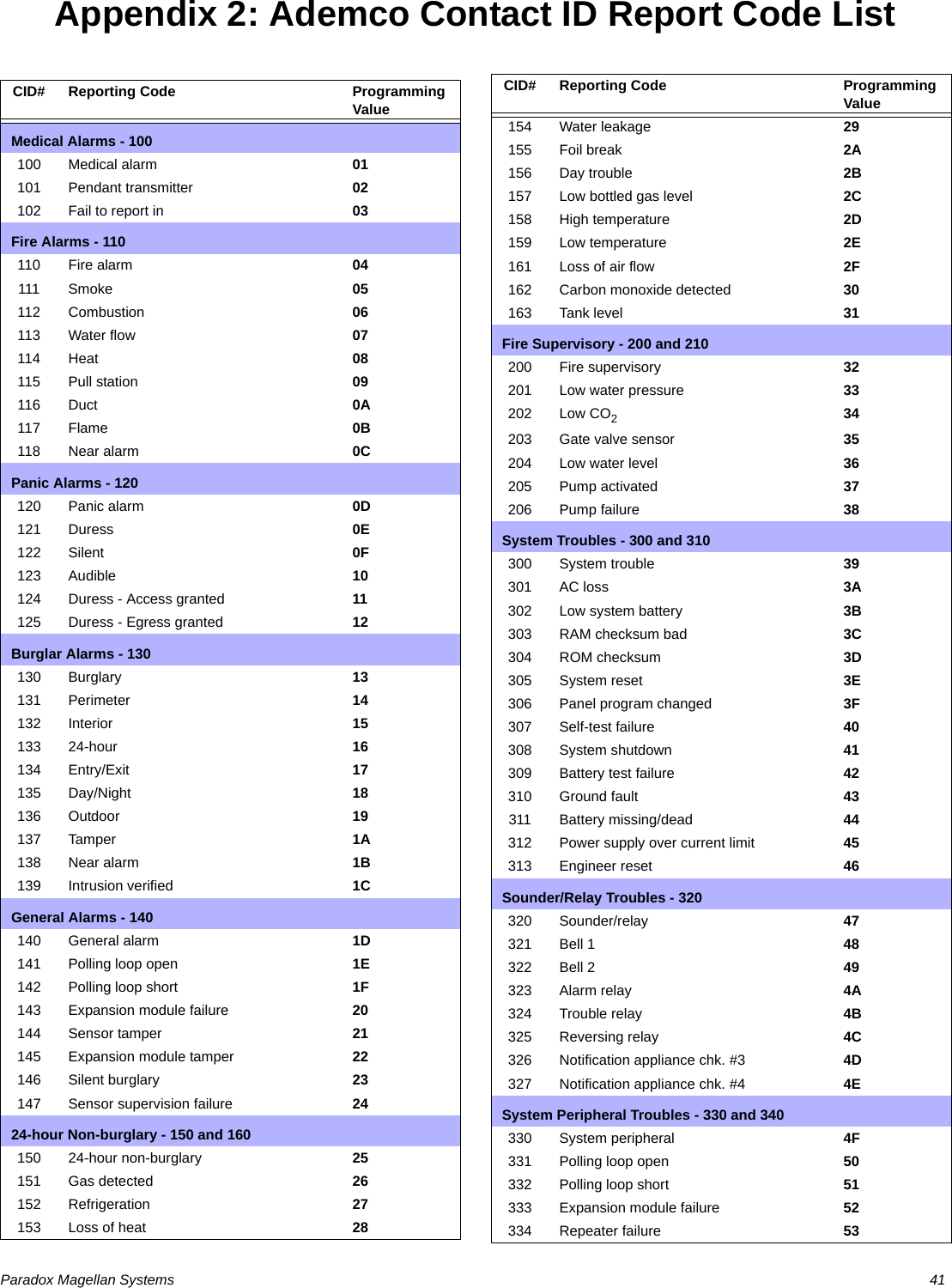
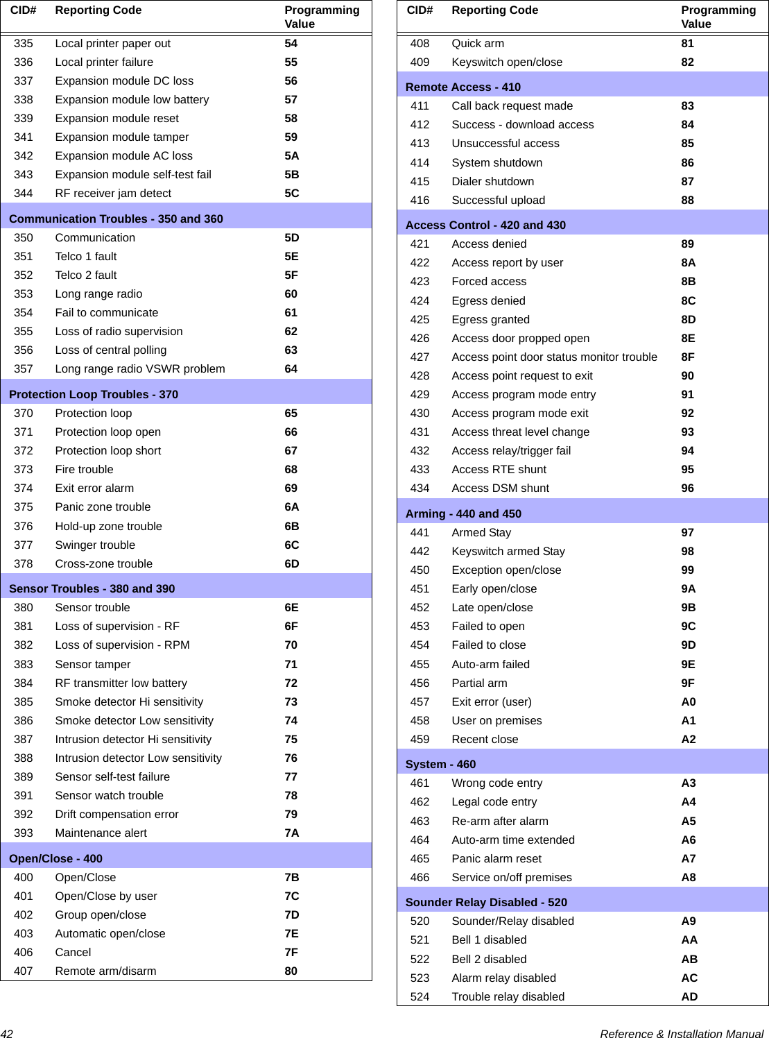
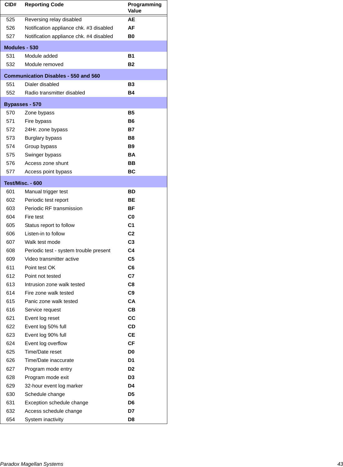
![Paradox Magellan Systems 27Reporting and Dialer SettingsReport CodesA report code is a 1- or 2-digit hexadecimal value consisting of digits from 1 to F. Each section from [120] to [156] represents a set of up to four specific events and each of these events can be programmed with a separate 1- or 2-digit report code.Only the Ademco Slow, Silent Knight, and Sescoa formats support 1-digit report codes. To program a 1-digit report code, press the [0] key followed by the desired hexadecimal digit or vice versa. When a specific event occurs, the console will attempt to transmit the programmed report code to the monitoring station. The method of report code transmission is defined by the Reporting Formats (see page 30) and the Event Call Direction (see page 31). These two items define how and where the report codes are transmitted. If you are using the Ademco Contact ID format, sections [120] to [156] do not have to be programmed (see Appendix 2: Ademco Contact ID Report Code List on page 41). For more information, refer to Reporting Formats (see page 30). The following sub-sections provide a brief description of the events that the Magellan console can report.Arming Report CodesSections [120] to [123]A report code can be programmed for each of the 16 User codes. When using an Access code to arm the system, the Magellan console can send the appropriate report code to the monitoring station, identifying which user armed the system.Special Arming Report CodesSections [124] and [125]Whenever the system is armed using one of the special arming features listed below, the console can send the appropriate report code to the monitoring station identifying how the system was armed.Section [124]• Timed Auto-arming: The system has armed itself at the programmed time (see page 22). • Late to Close: Reports every day at the time specified by the Auto-arm Timer (see page 22). • No Movement: The system has armed itself after the programmed period without movement (see No Movement Auto-Arming on page 22).• Partial Arming: The system was Stay, Instant or Force Armed or armed with bypassed zones.Section [125]• Quick Arming: The system was armed using a One-touch Arming feature (see page 23).• Arming via PC: The system was armed using the WinLoad software. Disarming Report CodesSections [126] to [129]A report code can be programmed for each of the 16 User codes. Whenever an Access code is used to disarm the system or an alarm, the Magellan console can send the appropriate report code to the monitoring station, identifying which user disarmed the system. The Disarming and the Special Disarming report codes can be transmitted every time the system is disarmed or only when the system is disarmed after an alarm (see Disarming Reporting Options on page 33).Special Disarming Report CodesSection [130]Whenever using one of the special disarming features, the Magellan console can send the report code to the monitoring station, identifying how the system was disarmed.• End Auto-arm: The system is disarmed during the Timed Auto-arm's 60-second Exit Delay (see page 22). Only reports if Disarming Reporting Options (see page 33) are set to always report disarming. • Disarm via PC: System is disarmed using the WinLoad software.Zone Alarm Report CodesSections [131] to [138]A report code can be programmed for each of the 32 available zones. Whenever a zone generates an alarm, the console can send the appropriate report code to the monitoring station, identifying which zone generated an alarm.Zone Alarm Restore Report CodesSections [139] to [146]A report code can be programmed for each of the 32 available zones. The Magellan console can transmit these report codes to the monitoring station identifying which zone was restored. A zone is restored when it closes after generating an alarm or once the bell has cut off after alarm generation. Please refer to Zone Alarm Restore Report Codes on page 27. Special Alarm Report CodesSections [147] and [148]Whenever the system generates an alarm due to one of the conditions listed below, the control panel can send the appropriate report code to the monitoring station identifying the type of alarm.Section [147]• Non-Medical Emergency Panic: Panic keys [1] and [3] (see page 26) or the appropriate button(s) on a remote control (see page 20) have been pressed.• Auxiliary Panic: Panic keys [4] and [6] (see page 26) or the appropriate button(s) on a remote control (see page 20) have been pressed.](https://usermanual.wiki/Paradox-Security-Systems/MG6130.User-Manual-1/User-Guide-819069-Page-29.png)
![28 Reference & Installation Manual• Fire Panic: Panic keys [7] and [9] (see page 26) or the appropriate button(s) on a remote control (see page 20) have been pressed.• Recent Closing: Reports when an alarm is generated after arming the system within the period defined by the Recent Close Delay (see page 32).Section [148]• Auto-zone Shutdown: A zone communicates more than the programmed number of transmissions in a single armed period (see page 17). • Duress: A Duress code is keyed in (see page 14). • Paramedical alarmZone Tamper Report CodesSection [149] to [156]A report code can be programmed for each of the 32 available zones. Whenever a tamper or wire fault occurs on a zone, the Magellan console can send the appropriate report code to the monitoring station identifying which zone was tampered.If Tamper Recognition (see page 24) is disabled, the console will not report the occurrence of any tampers, wire faults or tamper restores.Zone Tamper Restore Report CodesSections [157] to [164]A report code can be programmed for each of the 32 available zones. Whenever a tampered zone is restored, the Magellan console can send the appropriate report code to the monitoring station identifying which zone has been restored.If Tamper Recognition (see page 24) is disabled, the console will not report the occurrence of any tampers, wire faults or tamper restores.System Trouble Report CodesSection [165] to [167]Whenever the system generates one of the instances listed below, the console can send the appropriate report code to the monitoring station identifying the type of system trouble.Section [165]• AC Failure: Magellan has detected a loss of AC power. Transmission of this report code can be delayed (see Power Failure Report Delay on page 33).• Battery Failure: The backup battery is disconnected or battery voltage is ≤ (less than or equal to) a certain voltage.• Timer Loss: The console has detected a loss in time or clock failure.Section [166]• Unit Tamper: A tamper has been detected on the console itself (see Console Tamper Supervision on page 36).• Fail To Communicate: The Magellan console has failed all attempts to communicate with the monitoring station. The report code will be transmitted upon the next successful attempt.• Wireless Low Battery: The battery voltage of a wireless transmitter (motion detector or contact switch) has dropped below recommended limits.• Tx Supervision Loss: Check-in Supervision (see page 24) has been enabled and a transmitter is no longer communicating with the system.Section [167]• RF Jamming Supervision: The Magellan console has encountered RF Jamming (see RF Jamming Supervision on page 33).System Trouble Restore CodesSections [168] to [169]Whenever the system restores one of the troubles listed in sections [165] to [167] (see System Trouble Report Codes on page 28), the Magellan console can send the appropriate report code to the monitoring station identifying the type of system trouble restored. If Telephone Line Monitoring is enabled (see page 32), use the first two digits to program a TLM Restore report code that the console can transmit.Special Reporting CodesSections [171] and [172]Whenever the system generates one of the instances listed below, the Magellan console can send the appropriate report code to the monitoring station identifying the type of system occurrence.Section [171]• Cold Start: The console was completely shut down (no battery, no AC) and then was restarted.• Test Report: A test report has been generated automatically (see page 32).• WinLoad Logout: The console has ended communication with WinLoad.Section [172]• Installer logon: Installer has entered the programming mode.• Installer Logout: Installer has exited the programming mode.• Closing Delinquency: The last time the system was armed is greater than the programmed Closing Delinquency timer (see page 23).Wireless Module Trouble Report CodesSection [173] to [174]Whenever the system generates one of the instances listed below, the console can send the appropriate report code to the monitoring station identifying the type of wireless module trouble.Section [173]• PGM Supervision Loss: The console has lost communication with a wireless PGM.• PGM Tamper: The anti-tamper switch of a PGM has been triggered. • Keypad Supervision Loss: The console has lost communication with a wireless keypad.• Keypad Battery Trouble: The battery voltage of a keypad has dropped below recommended limits.Section [174]](https://usermanual.wiki/Paradox-Security-Systems/MG6130.User-Manual-1/User-Guide-819069-Page-30.png)
![Paradox Magellan Systems 29• Keypad AC Failure: The AC voltage of a keypad has dropped below recommended limits.• Repeater Supervision Loss: The console has lost communication with a wireless repeater.• Repeater Battery Trouble: The battery voltage of a repeater has dropped below recommended limits.• Repeater AC Failure: The AC voltage of a repeater has dropped below recommended limits.Wireless Module Trouble Restore CodesSections [175] to [176]Whenever the system restores one of the troubles listed in sections [173] to [174] (see System Trouble Report Codes on page 28), the Magellan console can send the appropriate report code to the monitoring station identifying the type of system trouble restored. If Telephone Line Monitoring is enabled (see page 32), use the first two digits to program a TLM Restore report code that the console can transmit.Console Telephone NumbersMagellan can dial up to two different monitoring station telephone numbers and one Pager telephone number. You can enter any digit from 0 to 9 and any special keys or functions (see Table 7 on page 29) up to a maximum of 32 digits. If the number is less than 32 digits, press the left [ACTION] key (OK) to save the message.In UL installations, only one telephone number is allowed.Table 7: Special Keys for Telephone NumbersMonitoring Station Telephone Numbers (MSTNs)Section [111] = Monitoring Station Telephone Number 1Section [112] = Monitoring Station Telephone Number 2The Magellan console uses the MSTNs (Monitoring Station Telephone Numbers) programmed in sections [111] and/or [112] to connect and communicate with the monitoring station. The following situations also apply:• If after eight attempts of calling one monitoring station telephone number have failed, the console will then dial the backup telephone number (if section [099] option [1] is enabled. See MSTN 2 as Backup Number on page 29). • If the Alternate Dial option (see page 31) is enabled, the console will dial the programmed backup telephone number after every failed attempt (if section [099] option [1] is enabled. See MSTN 2 as Backup Number on page 29). • If no backup telephone number is programmed, the console will never report to the backup telephone number. For more information on how these telephone numbers are used, please refer to Event Call Direction on page 31 and Reporting Formats on page 30. Also refer to Delay Between Dialing Attempts on page 31.For UL installations, the number of dialing attempts shall not exceed 10.MSTN 2 as Backup NumberSection [099]: Option [1]Option [1] OFF = Use MSTN 2 as a monitoring station telephone number onlyOption [1] ON = MSTN 2 can be used a backup telephone number (default)MSTN 2 can also be used as a backup telephone number. If section [099] option [1] is enabled (ON) the console will use MSTN 2 as a backup telephone number.For more information, please refer to Monitoring Station Telephone Numbers (MSTNs) on page 29 and Alternate Dial Option on page 31.Pager Telephone NumberSection [113]The Magellan console uses the Pager telephone number programmed in section [113] to connect and communicate the numeric pager message programmed in section [114] (see Pager Reporting Message on page 29) to a pager.Pager Reporting MessageSection [114]: 32-digit decimal number (0 to 9 as well as [*] and [#]) Program the desired numeric message you wish to send whenever the console dials the Pager telephone number in section [114]. If the message is less than 32 digits, press the left [ACTION] key (OK) to save the message.Voice Message Telephone NumbersThe Magellan console will use up to five Voice Message telephone numbers (which are programmed in the Installer menu; refer to the Magellan Quick Setup Guide for more information) to play a pre-recorded message to an external telephone or cellular telephone. Please note the following when programming and using this feature:• The console will only dial a Voice Message telephone number when the system is in alarm. The console begins with the first programmed Voice Message telephone number.• When the call is connected, the console will play the pre-recorded message and the zone labels of all the zones that are in alarm.• Once the telephone call from the Magellan console is received, the [#] key on the telephone can be pressed twice to acknowledge and end the message or the [1] can be pressed to use the speakerphone feature* and talk through the Magellan console. The [2] key can be pressed to disarm the system. The console will ask for an access code, and if granted, will disarm the system and enter Access Mode. Keys to press Action or Value[*] *[#] #Center [ACTION] (pause) key Add a 4-second pause to the telephone number. Press the key and a “P” will be inserted into the telephone number](https://usermanual.wiki/Paradox-Security-Systems/MG6130.User-Manual-1/User-Guide-819069-Page-31.png)
![30 Reference & Installation Manual• The console will repeat the message a programmed amount of times (see Voice Message Repetitions on page 30) if no acknowledgement is immediately received.• If no acknowledgement is received before the number of repetitions has elapsed, the console will then call the next programmed Voice Message telephone number and repeat the process.• After calling the last programmed Voice Message telephone number without an acknowledgement, the console will once again call the first Voice Message telephone number and repeat the process a maximum of three times.• If no acknowledgement is received after the third time, the console will generate a Fail to Comm. event and trouble.* The speakerphone feature is only available with the MG-6160.Voice Message RepetitionsSection [079]: 001 to 010 repetitions; Default = 3 repetitions; Maximum = 10 repetitionsThis feature determines the amount of times the console will repeat the pre-recorded message played with the Voice Message telephone number without receiving an acknowledgement. Enter any 3-digit number from 001 to 010 into section [079] to program the Voice Message Repetitions feature.Service Telephone NumberSection [116]When a specific trouble occurs (Fail to Comm., Console Tamper or Supervision Loss), the console will offer you the option of calling the telephone number programmed in section [116]. After selecting the option, the console becomes a speakerphone*.* The speakerphone feature is only available with the MG-6160.Refer to the Magellan User Guide for more information on using this feature.Utility ReportingWithin the Utility Reporting menu, customize what events and when these events will be reported to the user. One of five report types can be programmed to have the Magellan console call the user on up to two different telephone numbers with a pre-recorded voice message when certain conditions are met. Once the telephone call from the Magellan console is received, the [#] key on the telephone can be pressed twice to acknowledge and end the message or the [1] can be pressed to use the speakerphone feature* and talk through the Magellan console.* The speakerphone feature is only available with the MG-6160.To program the Utility Reporting feature using the Magellan console:1. Press [MENU] and then press the [4] key.2. Enter the [INSTALLER CODE] and then press the [3] key.3. Press [NEXT] until the Utility Reporting screen appears, then press [OK].4. Press [NEXT] until the desired telephone number appears, then press [OK].5. Enter the desired telephone number and then press [OK] twice.6. Press [NEXT] until the desired report type appears, then press [OK] (see Report Types on page 30).7. Press [NEXT] until the Record Alrm Mes? screen appears, then press [OK].8. Record the alarm message.Report TypesThere are four report types that can be used with Utility Reporting. •Disarm with user: The Magellan console calls the user when specific users disarm the system.•System troubles: The Magellan console calls the user when specific troubles appear.•Paramedic alarm: The Magellan console calls the user when specific users require non-medical emergency assistance and press the appropriate key on their remote controls.•Zone activation: The Magellan console calls the user when a specific zone is breached or opened.•Panic: There are four types of panic: Emergency, Auxiliary, Fire, and Duress Alarm.Refer to the Magellan User Guide for more information on using this feature.Console Account NumberSection [107]All report codes are preceded by a 4-digit or 3-digit Console Account Number to ensure correct identification of the Magellan console. The Console account number can be any hexa-digit from 1 to F. To enter a 3-digit account number, simply press the [1] key from the center keypad, followed by the 3-digit account number. Also, when using 3-digit account numbers, you must use 1-digit report codes.Reporting FormatsSection [105] = Reporting format for MSTN 1Section [106] = Reporting format for MSTN 2The reporting formats apply only to the MSTNs (Monitoring Station Telephone Numbers) programmed in sections [111] and [112] (page 29)The Magellan console can use a number of different reporting formats and each monitoring station telephone number can be programmed with a different reporting format. The three digits entered into section [105] represent the reporting format used to communicate with Monitoring Station Telephone Number 1 while the three digits entered into section [106] represent the reporting format used to communicate with Monitoring Station Telephone Number 2.Table 8: Reporting Formats3-digit Value Reporting Format001 Ademco slow (1400Hz, 1900Hz, 10BPS)002 Silent Knight Fast (1400Hz, 1900Hz, 10BPS)003 SESCOA (2300Hz, 1800Hz, 20BPS)004 Ademco Contact ID](https://usermanual.wiki/Paradox-Security-Systems/MG6130.User-Manual-1/User-Guide-819069-Page-32.png)
![Paradox Magellan Systems 31UL Note: The installer is required to verify the complete compatibility of the DAC Receiver and formats at least once per year.If you are using any report format other than SIA in sections [105] and [106] and you would like to transmit an “A”, press [0] on the main keypad; if you would like to enter a space (non-reportable digit), press the [1] key on the center keypad.Standard Pulse FormatsThe Magellan console can use the Ademco slow, Silent Knight and SESCOA standard pulse reporting formats (see Table 8 on page 30).Ademco Contact IDAdemco Contact ID is a fast communicator format that uses tone reporting instead of pulse reporting. This communicator format also uses a pre-defined list of industry standard messages and report codes that will suit most of your basic installation needs.• To manually program the report codes, use the 2-digit hexadecimal values from Appendix 2: Ademco Contact ID Report Code List on page 41. • Enter 00 to disable reporting or FF to use the default report code from Appendix 1: Automatic Report Code List on page 39.SIA FSKSIA FSK is a fast communicator format that uses tone reporting instead of pulse reporting. This communicator format uses a pre-defined list of industry standard messages and report codes that will suit most basic installation needs.Please refer to Appendix 1: Automatic Report Code List on page 39 for a complete list of the format’s pre-defined industry standard messages and report codes.Event Call DirectionSection [100]: Options [1] to [3]; Arming/DisarmingOption [1] ON = Call MSTN 1Option [2] ON = Call MSTN 2Option [3] ON = Call Pager telephone numberSection [100]: Options [5] to [7]; Alarm/Alarm RestoreOption [5] ON = Call MSTN 1Option [6] ON = Call MSTN 2Option [7] ON = Call Pager telephone numberSection [101]: Options [1] to [3]; Tamper/Tamper RestoreOption [1] ON = Call MSTN 1Option [2] ON = Call MSTN 2Option [3] ON = Call Pager telephone numberSection [101]: Options [5] to [7]; Trouble/Trouble RestoreOption [5] ON = Call MSTN 1Option [6] ON = Call MSTN 2Option [7] ON = Call Pager telephone numberSection [102]: Options [1] to [3]; SpecialOption [1] ON = Call MSTN 1Option [2] ON = Call MSTN 2Option [3] ON = Call Pager telephone numberThe events are divided into five groups (see above) where each event group can be programmed to dial up to three telephone numbers (MSTN 1 & 2 and the Pager telephone number) with one as a possible backup (see MSTN 2 as Backup Number on page 29).• When a reportable event occurs in the system, the Magellan console will begin dialing the numbers sequentially starting from MSTN 1 (if enabled), skipping any disabled numbers and stopping once all selected telephone numbers have been called.• After eight failed attempts at trying to call the monitoring station, the console will then dial the selected backup telephone number (if enabled; see MSTN 2 as Backup Number on page 29). • If the Alternate Dial option (see page 31) is enabled, the console will dial the programmed backup telephone number (if enabled, see MSTN 2 as Backup Number on page 29) after every failed attempt. • If no backup telephone number is programmed or section [099] option [1] is disabled (OFF, see page 31), the console will never report to the backup telephone number. For more information, please refer to Monitoring Station Telephone Numbers (MSTNs) on page 29, Alternate Dial Option on page 31, MSTN 2 as Backup Number on page 29 and Delay Between Dialing Attempts on page 31.Example: The system is armed and zone 1 has been breached causing an alarm. If options [5] and [7] are OFF and option [6] is ON in section [100], the console will attempt to communicate with MSTN 2 in order to transmit the Zone 1 Alarm Report Code programmed in section [131].Delay Between Dialing AttemptsSection [076]: 001 to 255 seconds; 000 = disabled; Default = 20 secondsThis delay determines the amount of time the Magellan console will wait between each dialing attempt. Alternate Dial OptionSection [098]: Option [5]Option [5] OFF = Alternate dial disabled (default)Option [5] ON = Alternate dial enabledWith option [5] OFF, the Magellan console will dial the programmed backup telephone number MSTN 2 (see MSTN 2 as Backup Number on page 29) only after all attempts to call MSTN 1 have failed. With option [5] ON, the console will dial the backup telephone number after every failed attempt.Force Dial OptionSection [098]: Option [6]Option [6] OFF = Force dial disabledOption [6] ON = Force dial enabled (default)005 SIA FSK006 Ademco Express (DTMF 4+2)](https://usermanual.wiki/Paradox-Security-Systems/MG6130.User-Manual-1/User-Guide-819069-Page-33.png)
![32 Reference & Installation ManualWhen option [6] is enabled, the Magellan console will dial a telephone number even if no dial tone is present after 3 seconds. Dialing MethodSection [098]: Option [7]Option [7] OFF = Pulse dialing Option [7] ON = Tone / DTMF dialing (default)When option [4] is ON, the Magellan console is set for Tone/DTMF dialing. When option [4] is OFF, the console is set for pulse dialing. Refer to Pulse Ratio on page 32 for information on setting the pulse ratio.Pulse RatioSection [098]: Option [8]Option [8] OFF = European Pulse Ratio of 1:2 Option [8] ON = U.S.A. Pulse Ratio of 1:1.5 (default)When using Pulse dialing, you can select one of two Pulse Ratios. Although most European countries use the 1:2 pulse ratio, the 1:1.5 ratio may provide better results in some cases. The same applies for North American countries. If the 1:1.5 pulse ratio is not providing the desired results, the 1:2 ratio may be used.Switch to Pulse Dialing on 5th AttemptSection [098]: Option [3]Option [3] OFF = Switch to pulse dialing on fifth attempt disabled (default)Option [3] ON = Switch to pulse dialing on fifth attempt enabledWhen section [098] option [3] is ON, the Magellan console switches from tone/DTMF dialing to pulse dialing on the fifth attempt to report events to the monitoring station. The console continues to use pulse dialing until it establishes communication. When the console switches to another MSTN, it returns to tone/DTMF dialing and will once again switch to pulse dialing on the fifth attempt.Telephone Line Monitoring (TLM)Section [098]: Options [1] and [2]When enabled, the system verifies the existence of a telephone line once every second. A line test failure occurs when the TLM detects less than a certain voltage for the period defined by the TLM Fail Timer (see page 32). If the line test fails, the Magellan console generates one or more conditions as defined by the TLM settings below. These will be restored when the console detects the telephone line again. Table 9: Telephone Line Monitoring OptionsPlease note that when the dialer detects an incoming call, the TLM test will stop for 1 minute.If transmission is used off premises, telephone line monitoring must be used in UL installations.TLM Fail TimerSection [073]: 001 to 255 seconds; 000 = Disabled; Default = 32 secondsIf TLM does not detect the existence of a telephone line for the duration of this period, the control panel will generate the condition(s) defined by the TLM options (see Telephone Line Monitoring (TLM) on page 32).Recent Close DelaySection [066]: 001 to 255 seconds; 000 = Disabled; Default = DisabledIf after having armed the system, an alarm is generated within the period defined by the Recent Close Delay, the Magellan console will attempt to transmit the Recent Close report code programmed in section [139] (page 27). Auto-Test ReportSection [071]: 001 to 255 days; 000 = Disabled; Default = Disabled Section [084]: Time (HH:MM)The Magellan console will transmit the Test Report report code programmed into section [153] after the number of days programmed into section [071] has elapsed at the time programmed into section [084]. Use the 24-hour clock to program the time (i.e. 6:30PM = 18:30). The first Test Report will be transmitted within 24 hours after the feature is enabled at the time programmed in [084]. Example: Section [071] = 005 and section [084] = 13:00. The first Test Report will be sent at 1 PM that day and then the report will be sent every 5 days at 1 PM.Options Description[1] [2]OFF OFF TLM disabled (default)OFF ON Trouble only: Upon a line test failure, a TLM trouble will appear in the console’s Trouble Display.ON OFF Alarm if System Armed: Upon a line test failure, a TLM trouble will appear in the console’s Trouble Display and if the system is armed, the console will generate an alarm.ON ON Silent Alarm becomes Audible: Upon a line test failure, a TLM trouble will appear in the console’s Trouble Display and causes a silent zone or silent panic alarm to switch to audible.](https://usermanual.wiki/Paradox-Security-Systems/MG6130.User-Manual-1/User-Guide-819069-Page-34.png)
![Paradox Magellan Systems 33Power Failure Report DelaySection [070]: 001 to 255 minutes; 000 = Disabled; Default = 15 minutesThe Magellan console will transmit the AC Failure report code programmed in section [149] after the Power Failure Report Delay period has elapsed. Disarm Reporting Options Section [093]: Option [5]Option [5] OFF = Always report disarmingOption [5] ON = Report disarming only after alarm (default)With option [5] OFF, the Magellan console will send the Disarming report codes (see page 27) to the monitoring station every time the system is disarmed. With option [5] ON, the console will send the Disarming report codes to the monitoring station when the system is disarmed following an alarm.Zone Restore Report OptionsSection [094]: Option [2]Option [2] OFF = Report on Bell Cut-Off (default)Option [2] ON = Report on zone closureWith option [2] OFF, the Magellan console will send the Zone Alarm Restore report codes (see page 27) to the monitoring station when the zone has returned to normal and the Bell Cut-Off Timer (see page 24) has elapsed. With option [2] ON, the console will send the Zone Alarm Restore report codes to the monitoring station as soon as the zone returns to normal or when the system is disarmed.RF Jamming SupervisionSection [096]: Option [8]Option [8] OFF = RF Jamming Supervision disabled Option [8] ON = RF Jamming Supervision enabled (default)With option [8] ON, a trouble will be generated when the Magellan console’s RF signal is jammed or encounters interference for a minimum of 10 seconds.This feature must be enabled for use in UL installations.](https://usermanual.wiki/Paradox-Security-Systems/MG6130.User-Manual-1/User-Guide-819069-Page-35.png)
![34 Reference & Installation ManualProgrammable OutputsA PGM is a programmable output that toggles to its opposite state (i.e. a normally open PGM will close) when a specific event has occurred in the system. For example, a PGM can be used to activate bells or strobe lights, open/close garage doors and much more. When a PGM activates, the control panel triggers any device or relay connected to it. The Magellan console includes two onboard PGMs. It can support up to a total of four PGMs (e.g., two onboard PGMs + two wireless PGMs OR four wireless PGMs).Assigning PGMsSections [235] to [238]: PGMs 1 to 4Sections [235] to [238] represent PGMs 1 to 4. A PGM module assigned to a section ([235] to [238]) will be assigned to the PGM represented by the section.For example, a PGM module assigned to section [235] will be assigned to PGM1. To assign a PGM:1. Access the installer programming mode (see page 13).2. Enter the [SECTION] corresponding to the desired zone.3. Enter the 6-digit [SERIAL NUMBER] of the PGM module.The serial number is located on the inside of the PGM module.The PGM module must be activated once having been assigned to the Magellan console. To activate a PGM module, insert the batteries and close the cover. PGM 1 and 2 are onboard. PGM 3 and 4 are wireless.Setting PGM FunctionThis feature allows you to program the Magellan console to recognize PGM1 and/or PGM2 as a hardwire PGM (onboard) and PGM 3 and/or 4 as wireless. To set a PGM’s function:1. Press [MENU] + [4] + [INSTALLER CODE] + [7].2. Press [OK] to set the function of PGM1 or [NEXT] to set the function of PGM 2, 3, and/or 4. Press [OK] to set the function of the desired PGM module.3. Press [YES] to set the PGM as wireless.4. Open and then close the cover of the wireless PGM module. The PGM function has been set.5. To continue programming the module, follow the instructions on the Magellan console.To program the PGM’s activation event and/or deactivation event, see Onboard PGM Activation Event on page 34, Wireless PGM Activation Event on page 35, Onboard PGM Deactivation Event on page 34 and Wireless PGM Deactivation Event on page 35.If both PGM1 and PGM2 are set as hardwire (onboard), Magellan will ignore sections [260] to [267], and [280] to [283].Onboard PGM Activation EventSection [086] = PGM1 Activation EventSection [088] = PGM2 Activation EventThis feature allows you to program the Magellan console to activate a PGM when a specific event occurs in the system. The PGM will remain in its active state until the programmed PGM Deactivation Event (see page 34) occurs or when the PGM Delay (see page 34) elapses. To program a PGM Activation Event:1. Enter the section that corresponds to the desired PGM; PGM1 = [086], PGM2 = [088].2. Enter the [EVENT GROUP #]. 3. Enter the [SUB-GROUP #]. The AC Loss PGM event (Event Group #28, Event Sub-group #01) will only occur after the Power Failure Report Delay elapses (see page 33).For the Event List, see the PGM Table in the Magellan Programming Guide.Onboard PGM Deactivation EventSection [087] = PGM1Section [089] = PGM2After PGM activation (see Onboard PGM Activation Event on page 34), the PGM will return to its normal state (deactivate) when the programmed PGM Deactivation Event occurs. To program a Deactivation Event:1. Enter section that represents the desired PGM; PGM1 = [087], PGM2 = [089].2. Enter the [EVENT GROUP #]. 3. Enter the [SUB-GROUP #].A PGM can also be set to deactivate after a programmed period elapses (see Onboard PGM Delay on page 34). If using the PGM Delay, sections [087] and [089] can be used as an additional PGM Activation Event.For the complete Event List, see the PGM Table in the Magellan Programming Guide.Onboard PGM Delay Section [068] = PGM1, Section [069] = PGM2001 to 255 seconds; 000 = Follow Deactivation Event; Default = 5 secondsInstead of deactivating the PGM on the occurrence of a specific event, the PGM will deactivate after the period programmed in here has elapsed. Enter 000 to have the PGMs deactivate with a PGM Deactivation Event (see page 34).If a PGM Delay is programmed, the corresponding PGM Deactivation Event can be used as an additional PGM Activation Event.](https://usermanual.wiki/Paradox-Security-Systems/MG6130.User-Manual-1/User-Guide-819069-Page-36.png)
![Paradox Magellan Systems 35PGM Normal State (Onboard Only)Section [090]: Options [7] (PGM1) and [8] (PGM2)Option [7] OFF = PGM1 Normally Open (default)Option [7] ON = PGM1 Normally ClosedOption [8] OFF = PGM2 Normally Open (default)Option [8] ON = PGM2 Normally ClosedA PGM toggles to its opposite state (i.e. a normally open PGM will close) when a specific event has occurred in the system. You can program each PGM output to be normally open (N.O.) or normally closed (N.C.) by enabling or disabling options [7] and [8] in section [090].PGM X10 Option (MG-6160 Only / Onboard Only)Section [091]: Options [7] (PGM1) and [8] (PGM2)Option [7] OFF = PGM1 used as programmable output (default)Option [7] ON = PGM1 used as X10 output 7Option [8] OFF = PGM2 used as programmable output (default)Option [8] ON = PGM2 used as X10 output 8With section [091] options [7] and [8] enabled (ON), PGMs 1 and 2 will follow the ON/OFF state of X10 outputs 7 and 8. Therefore the PGMs will function as follows:• When X10 output 7 is enabled, PGM1 will activate. When X10 output 7 is disabled, PGM1 will deactivate.• When X10 output 8 is enabled, PGM2 will activate. When X10 output 8 is disabled, PGM2 will deactivate.When section [091] options [7] and [8] are enabled, the PGM outputs will disregard their PGM activation and deactivation events (sections [086] to [089]).Wireless PGM Activation EventSection [260] = Wireless PGM1 Activation EventSection [262] = Wireless PGM2 Activation EventSection [264] = Wireless PGM3 Activation EventSection [266] = Wireless PGM4 Activation EventThis feature allows you to program the MG-2WPGM modules to activate a wireless PGM when a specific event occurs in the system. The wireless PGM will remain in its active state until the programmed Wireless PGM Deactivation Event (see page 35) occurs or when the Wireless PGM Delay (see page 35) elapses. To program a Wireless PGM Activation Event:1. Enter the section that corresponds to the desired wireless PGM; Wireless PGM1 = [260], Wireless PGM2 = [262], Wireless PGM3 = [264], Wireless PGM3 = [266].2. Enter the [EVENT GROUP #]. 3. Enter the [SUB-GROUP #]. The AC Loss PGM event (Event Group #28, Event Sub-group #01) will only occur after the Power Failure Report Delay elapses (see page 33).For the Event List, see the PGM Table in the Magellan Programming Guide.Wireless PGM Deactivation EventSection [261] = Wireless PGM1 Deactivation EventSection [263] = Wireless PGM2 Deactivation EventSection [265] = Wireless PGM3 Deactivation EventSection [267] = Wireless PGM4 Deactivation EventAfter a Wireless PGM activation (see Wireless PGM Activation Event on page 35), the wireless PGM will return to its normal state (deactivate) when the programmed Wireless PGM Deactivation Event occurs. To program a Wireless Deactivation Event:1. Enter section that represents the desired wireless PGM; Wireless PGM1 = [261], Wireless PGM2 = [263], Wireless PGM3 = [265], Wireless PGM3 = [267].2. Enter the [EVENT GROUP #]. 3. Enter the [SUB-GROUP #].A wireless PGM can also be set to deactivate after a programmed period elapses (see Wireless PGM Delay on page 35). If using the Wireless PGM Delay, sections [280] to [283] can be used as a second Wireless PGM Activation Event.For the complete Event List, see the PGM Table in the Magellan Programming Guide.Wireless PGM Delay Section [280] = Wireless PGM1, Section [281] = Wireless PGM2Section [282] = Wireless PGM3, Section [283] = Wireless PGM4000 = Follow Deactivation Event; 001 = 1s delay; 002 = 5s delay; 003 = 15s delay; 004 = 30s delay; 005 = 1min delay; 006 = 5min delay; 007 = 15min delay; 008 = 30min delay;Default = 000Instead of deactivating the wireless PGM on the occurrence of a specific event, the wireless PGM will deactivate after the period programmed in here has elapsed. Enter 000 to have the wireless PGMs deactivate with a Wireless PGM Deactivation Event (see page 35).If a Wireless PGM Delay is programmed, the Wireless PGM Deactivation Event can be used as a second Wireless PGM Activation Event.](https://usermanual.wiki/Paradox-Security-Systems/MG6130.User-Manual-1/User-Guide-819069-Page-37.png)
![36 Reference & Installation ManualSystem SettingsSoftware ResetSection [199]Performing a software reset will reset all programmed sections back to the factory defaults. To perform a software reset:1. Access the installer programming mode (see page 13).2. Enter section [199].You can also perform a software reset by removing power to the console, pressing and holding down the [*] and [#] keys and then reapplying power to the console.Installer LockSection [180]: 000 = Disabled; 147 = Lock Enabled; Default = DisabledProgram 147 into section [180] to lock all programming. Performing a hardware reset will not affect the current console settings. To remove the Installer Lock, enter 000.Console Tamper SupervisionSection [090]: Option [5]Option [5] OFF = Console Tamper Supervision disabled (default)Option [5] ON = Console Tamper Supervision enabledMagellan can be programmed to monitor its on-board tamper status. The console will follow its programmed Tamper Recognition options. Refer to Tamper Recognition Options on page 24 for more information.Console Audible Trouble WarningSection [090]: Option [2]Option [2] OFF = Console beep on trouble disabled (default)Option [2] ON = Console beep on trouble enabledWhen enabled, the console emits an intermittent beep tone whenever a trouble condition occurs in the system. The intermittent beep tone remains activated until the user enters the Trouble Display by pressing the left [ACTION] key (I). The intermittent beeps will re-initialize whenever a new trouble occurs or the trouble restores and re-occurs.The only trouble not covered by this feature is the AC Power Failure trouble. See AC Power Failure Warning on page 36.This feature must be enabled in UL installations.FM Tuner Option (MG-6160 only)Section [093]: Option [8]Option [8] OFF = FM tuner is disabled when the system is armed (default)Option [8] ON = FM tuner is enabled when system is armedWith section [093] option [8] ON, the Magellan’s radio is turned ON automatically after the system is armed (after the Exit Delay Timer has elapsed).Daylight Savings TimeSection [096]: Option [5]Option [5] OFF = Daylight Savings Time disabled (default)Option [5] ON = Daylight Savings Time enabledWith section [096] option [5] ON, Magellan adjusts the system’s clock (time) for daylight savings changes. At 2:00AM on the first Sunday of a full weekend in April, the console will add one hour to the programmed time (clock). At 2:00 AM on the last Sunday of a full weekend in October, the console will subtract one hour from the programmed time (clock).AC Power Failure WarningSection [096]: Option [6]Option [6] OFF = AC Power Failure Warning disabled (default)Option [6] ON = AC Power Failure Warning enabledWith this feature enabled, the console emits an intermittent beep tone whenever an AC power failure is detected. The intermittent beep tone remains activated until the user enters the Trouble Display by pressing the left [ACTION] key (i). The intermittent beeps will re-initialize whenever the trouble occurs or the trouble restores and re-occurs.This feature must be enabled in UL installations.The Trouble DisplayWhen the system experiences problems or is tampered with, the Information symbol ( ) will appear on the LCD screen and the light will illuminate. The potential troubles that the Magellan system can experience are listed below. To access the Trouble Display:1. Press the key.2. Use the [NEXT] key to scroll through the displayed troubles.3. Press the [OK] key to view details on the desired trouble.Trouble DescriptionBypass There is a zone (or zones) that is bypassed in the system.Alarm Memory An alarm has occurred in the system. The zones displayed went into alarm.Console Low Bat The backup battery pack is disconnected or needs to be recharged or replaced.Doorbell Low Bat Wireless transmitter being used as a doorbell (see page 19) requires its batteries changed.Zone Low Battery Zone(s) displayed indicate(s) where a wireless transmitter’s battery needs to be replaced.](https://usermanual.wiki/Paradox-Security-Systems/MG6130.User-Manual-1/User-Guide-819069-Page-38.png)
![Paradox Magellan Systems 37* When a communication failure trouble is acknowledged by pressing [OK], you will be given the option to call your service provider. See Service Telephone Number on page 30.Clock Loss The time and date were reset to default. To reprogram:1. Press the [12HRS] key to display the time using the 12-hour clock or the [24HRS] key to display the time using the 24-hour clock.2. Enter the desired time and then press [OK].3. Enter the date and then press [OK].AC Failure Power failure detected. The system is running on the backup battery pack.Supervision Trouble Zone(s) and/or wireless output(s) displayed has/have not sent a check-in signal within the programmed interval (see page 24).Console Tamper The Magellan console was tampered with.Zone Tamper Zone(s) and/or wireless output(s) displayed was/were tampered with.Fail to Communicate with Central*The Magellan console has failed to contact the monitoring station.Fail to Communicate with Voice Reporting*The Magellan console has failed to contact telephone number programmed for Voice reporting.Fail to Communicate to Pager*The Magellan console has failed to contact telephone number programmed for Pager reporting.Fail to Communicate with PC*The Magellan console is unable to communicate with the WinLoad software.Fail to Communicate with Voice Utility*The Magellan console has failed to contact telephone number programmed for Voice Utility reporting.Trouble Description](https://usermanual.wiki/Paradox-Security-Systems/MG6130.User-Manual-1/User-Guide-819069-Page-39.png)
![38 Reference & Installation ManualWinLoad Software SettingsPanel Answer OptionsThe following two options define how Magellan answers an incoming call from a computer using the WinLoad Installer Upload/Download Software.Answering Machine OverrideSection [074]: 010 to 255 seconds; 000 = disabled; Default = disabledWhen using WinLoad to communicate remotely with an installation site that uses an answering machine or service, the answering machine override must be programmed. Using WinLoad, you will call Magellan, hang up, then call back. If the installation site is called back within the delay programmed in section [074], the console will override the answering machine or service by picking up the line after the first ring on the second call. You must wait at least 10 seconds before attempting the second call, otherwise, the console will think it is the same call. For details on how to use WinLoad, refer to the WinLoad On-line Help.Example: A security installation is using an answering machine set to answer after three rings. If section [074] has been programmed with 040 (40 seconds) and the second call is made within 40 seconds, Magellan will pick up the line on the first ring. If it takes more than 40 seconds, the console will not answer on the first ring and the answering machine will answer after three rings.Number of RingsSection [072]: 001 to 015 rings; 000 = disabled; Default = 008This value represents the number of rings Magellan will wait before picking-up the line. If the line is not answered after the number of programmed rings, the console will answer the call. You must wait at least 10 seconds before attempting the second call or Magellan will think it is the same call.Panel IdentifierSection [108]: 4-digit Hexadecimal number from 0000 to FFFFThis 4-digit code identifies the console to WinLoad before initiating communication. Magellan will verify that the Panel Identifier in the WinLoad software is the same as the code programmed in section [108]. If the codes do not match, the console will not establish communication. Therefore, be sure to program the same panel identifier code into both Magellan and WinLoad.PC PasswordSection [109]: 4-digit Hexadecimal number from 0000 to FFFFThis 4-digit password identifies the PC to Magellan before establishing communication. Program the same PC password into both the console and WinLoad. If the passwords do not match, WinLoad will not establish communication.PC Telephone NumberSection [115]Magellan will dial the number programmed in section [118] when trying to initiate communication with a computer using WinLoad. You can enter any digit from 0 to 9 and any special keys or functions (see Table 7 on page 29) up to a maximum of 32 digits.Call Back FeatureSection [098]: Option [4]Option [4] OFF = Call Back Feature disabled (default)Option [4] ON = Call Back Feature enabledThe Call Back feature provides additional security. When section [098] option [4] in ON and a computer using WinLoad attempts to communicate with Magellan, the console hangs up and calls the computer back to re-verify identification codes and re-establish communication. When Magellan hangs up, WinLoad automatically goes into Wait for Call mode, ready to answer when the console calls back. The PC Telephone number must be programmed (see PC Telephone Number on page 38).](https://usermanual.wiki/Paradox-Security-Systems/MG6130.User-Manual-1/User-Guide-819069-Page-40.png)
![Paradox Magellan Systems 39Appendix 1: Automatic Report Code ListSystem Event Default Contact ID Report Codewhen using sections [790] to [795] Default SIA Report Codewhen using sections [790] to [795]Arming with Master Code (##) 3 4A1 - Close by user CL - Closing ReportArming with User Code (##) 3 4A1 - Close by user CL - Closing ReportArming with Keyswitch (##) 3 4A9 - Keyswitch Close CS - Closing KeyswitchAuto Arming 3 4A3 - Automatic Close CA - Automatic ClosingArm with PC software 3 4A7 - Remote arm/disarm CL - Closing ReportLate To Close 3 4A4 - Late to Close OT - Late to CloseNo Movement 3 4A4 - Late to Close NA - No ActivityPartial arming 1 574 - Group bypass CG - Close AreaQuick arming 3 408 - Quick arm CL - Closing ReportClosing Delinquency 1 654 - System Inactivity CD - System InactivityDisarm with Master Code (##) 1 4A1 - Open by user OP - Opening ReportDisarm with User Code (##) 1 4A1 - Open by user OP - Opening ReportDisarm with Keyswitch (##) 1 4A9 - Keyswitch Open OS - Opening KeyswitchDisarm after alarm* with Master Code (##) 1 4A1 - Open by user OP - Opening ReportDisarm after alarm* with User Code (##) 1 4A1 - Open by user OP - Opening ReportDisarm after alarm* with Keyswitch (##) 1 4A1 - Keyswitch Open OS - Opening KeyswitchCancel alarm** with Master Code (##) 1 4A6 - Open by user OR - Disarm from AlarmCancel alarm** with User Code (##) 1 4A6 - Open by user OR - Disarm from AlarmCancel alarm** with Keyswitch (##) 1 4A6 - Keyswitch Open OS - Opening KeyswitchAuto Arming Cancellation 1 4A5 - Deferred Open/Close CE - Closing ExtendDisarm with PC software 1 4A7 - Remote arm/disarm OP - Opening ReportDisarm after an alarm with PC software 1 4A7 - Remote arm/disarm OR - Disarm From AlarmQuick disarm 1 408 - Quick disarm OP - Opening ReportZone Bypassed (##) 1 57A - Zone bypass UB - Untyped Zone BypassZone alarm (##) 1 13A - Burglary Alarm BA - Burglary AlarmFire alarm (##) 1 11A - Fire alarm FA - Fire AlarmZone alarm restore (##) 3 13A - Burglary Alarm Restore BH - Burglary Alarm RestoreFire alarm restore (##) 3 11A - Fire alarm Restore FH - Fire Alarm RestorePanic 1 - Non-Medical Emergency 1 12A - Panic alarm PA - Panic AlarmPanic 2 - Medical 1 1AA - Medical alarm MA - Medical AlarmPanic 3 - Fire 1 115 - Pull Station FA - Fire AlarmRecent closing 3 4AA - Open/Close CR - Recent ClosingGlobal zone shutdown 1 574 - Group bypass CG - Close AreaDuress alarm 1 121 - Duress HA - Hold-up AlarmZone shutdown (##) 1 57A - Zone bypass UB - Untyped Zone BypassZone tampered (##) 1 144 - Sensor tamper TA - Tamper AlarmZone tamper restore (##) 3 144 - Sensor tamper restore TR - Tamper RestoralKeypad Lockout 1 421 - Access denied JA - User Code Tamper* An armed system is or was in alarm and was disarmed by a user.** A disarmed system is or was in alarm (e.g. 24Hr. zone) and was disarmed by a user.](https://usermanual.wiki/Paradox-Security-Systems/MG6130.User-Manual-1/User-Guide-819069-Page-41.png)
![40 Reference & Installation ManualAC Failure 1 3A1 - AC loss AT - AC TroubleBattery Failure 1 3A9 - Battery test failure YT - System Battery TroubleAuxiliary supply trouble 1 3AA - System trouble YP - Power Supply TroubleBell output current limit 1 321 - Bell 1 YA - Bell FaultBell absent 1 321 - Bell 1 YA - Bell FaultClock lost 1 626 - Time/Date inaccurate JT - Time ChangedFire loop trouble 1 373 - Fire trouble FT - Fire TroubleTLM trouble restore 3 351 - Telco 1 fault restore LR - Phone Line restoralAC Failure restore 3 3A1 - AC loss restore AR - AC RestoralBattery Failure restore 3 3A9 - Battery test restore YR - System Battery RestoralAuxiliary supply trouble restore 3 3AA - System trouble restore YQ - Power Supply restoredBell output current limit restore 3 321 - Bell 1 restore YH - Bell RestoredBell absent restore 3 321 - Bell 1 restore YH - Bell RestoredClock programmed 3 625 - Time/Date Reset JT - Time ChangedFire loop trouble restore 3 373 - Fire trouble restore FJ - Fire Trouble RestoreCombus fault 1 333 - Expansion module failure ET - Expansion TroubleModule tamper 1 145 - Expansion module tamper TA - Tamper AlarmModule ROM_RAM_error 1 3A4 - Rom checksum bad YF - Parameter Checksum FailModule TLM trouble 1 352 - Telco 2 fault LT - Phone Line troubleModule fail to communicate to monitoring station. 1 354 - Fail to communicate YC - Communication FailsPrinter fault 1 336 - Local printer failure VT - Printer TroubleModule AC Failure 1 3A1 - AC loss AT - AC TroubleModule battery failure 1 3A9 - Battery test failure YT - System Battery TroubleModule Auxiliary supply trouble 1 3AA - System trouble YP - Power Supply TroubleBus fault restore 3 333 - Expansion module failure restore ER - Expansion RestoralModule tamper restore 3 145 - Expansion module tamper restore TR - Tamper RestoralModule ROM_RAM_error restore 3 3A4 - Rom checksum bad restore YG - Parameter ChangedModule TLM restore 3 352 - Telco 2 fault restore LR - Phone Line RestoralPrinter fault restore 3 336 - Local printer failure restore VR - Printer RestoreModule AC restore 3 3A1 - AC loss restore AR - AC RestoralModule battery restore 3 3A9 - Battery test failure restore YR - System Battery RestoralModule Auxiliary supply restore 3 3AA - System trouble restore YQ - Power Supply RestoredFail to communicate with monitoring station 1 354 - Fail to communicate YC - Communication FailsModule RF low battery 1 384 - RF transmitter low battery XT - Transmitter Battery TroubleModule RF battery restore 3 384 - RF transmitter battery restore XR - Transmitter Battery RestoralModule RF supervision trouble 1 381 - Loss of supervision - RF US - Untype Zone SupervisionModule RF supervision restore 3 381 - Supervision restore - RF UR - Untyped Zone RestoralCold Start 1 3A8 - System shutdown RR - Power UpWarm Start 1 3A5 - System reset YW - Watchdog ResetTest Report engaged 1 6A2 - Periodic test report TX - Test ReportPC software communication finished 1 412 - Successful - download access RS - Remote Program SuccessInstaller on site 1 627 - Program mode Entry LB - Local ProgramInstaller programming finished 1 628 - Program mode Exit LS - Local Program SuccessSystem Event Default Contact ID Report Codewhen using sections [790] to [795] Default SIA Report Codewhen using sections [790] to [795]](https://usermanual.wiki/Paradox-Security-Systems/MG6130.User-Manual-1/User-Guide-819069-Page-42.png)