Paradox Security Systems MG6130 Wireless Console User Manual MAGELLAN EP06
Paradox Security Systems Wireless Console MAGELLAN EP06
UserManual.wiki
>
Paradox Security Systems
>
MG6130 User Manual
>
User Manual 2
Contents
1.
User Manual 1
2.
User Manual 2
3.
User Manual 3
User Manual 2
Navigation menu
Upload a User Manual
Namespaces
Wiki Guide
HTML
PDF
Info
Views
User Manual
Discussion / Help
Navigation
![2Programming GuideThings You Should KnowAbout This Programming GuideThis programming guide should be used in conjunction with the Magellan Reference & Installation Manual which can be downloaded from our website at paradox.com. Use this guide to record the settings programmed for this console.ConventionsInstaller Code (Default: 0000 / 000000)The Installer code is used to enter programming mode (see Entering Programming Mode on page 2), which allows you to program all the features, options and commands of the Magellan console except user codes. The Installer code can be 4 or 6 digits in length (see section [090] option [1] on page 7) where each digit can be any value from 0 to 9. See section [181] on page 13 to change the default code.Maintenance Code (Default: 1111 / 111111)The Maintenance code is similar to the Installer code. It can be used to enter programming mode (see Entering Programming Mode on page 2), which allows you to program all the features, options and commands except for the Magellan console’s communication settings (sections [108] to [112], sections [180] to [182]) as well as any user codes. The Maintenance code can be 4 or 6 digits in length (see section [090] option [1] on page 7) where each digit can be any value from 0 to 9. See section [182] on page 13 to change the default code (Installer only).Master Code (Default: 1234 / 123456)With the System Master code a user can use any arming method and can program user codes. The System Master code can be 4 or 6 digits in length (see section [090] option [1] on page 7), where each digit can be any digit from 0 to 9. The System Master code cannot be changed by the Installer or Maintenance code, but it can be reset to default. See section [200] on page 13 to reset to default.Entering Programming ModeUse the built-in keypad to access Magellan’s installer programming mode. To access programming mode:1. Press and hold the [0] key.2. Enter your [INSTALLER CODE] or [MAINTENANCE CODE].3. Enter the 3-digit [SECTION] you wish to program.4. Enter the required [DATA].5. Press the [*] key to clear data or to go back one step. Press the [#] key to save changes.There are two methods that can be used to enter data when in programming mode: Single Digit Data Entry and Feature Select Programming methods.Single Digit Data Entry MethodAfter entering programming mode, some sections will require that you enter decimal values from 000 to 255. Other sections will require that you enter hexadecimal values from 0 to F. The required data will be clearly indicated in this manual. When entering the final digit in a section, Magellan will automatically save and advance to the next section. Refer to Figure 1 on page 3 to see the keys and their equivalent decimal and/or hexadecimal value.This symbol designates a warning or important information.This symbol designates a suggestion or reminder.This symbol designates a reference to another section, manual or guide.This symbol designates a feature that can also be programmed in the Installer menu which can be accessed by pressing [menu] and then entering your [INSTALLER CODE]. The icon will then be followed by the path or buttons that have to be pressed in order to access the feature once in the Installer menu. For example: = Once in the Installer menu, press the [4] key and then press the [6] key to access the desired feature.Refer to the Installer Menu Overview on the back cover for more information on accessing and using the Installer menu.J[4] J[6]](https://usermanual.wiki/Paradox-Security-Systems/MG6130.User-Manual-2/User-Guide-819070-Page-2.png)
![Magellan 3Feature Select Programming MethodAfter entering certain sections, eight options will be displayed where each option from [1] to [8] represents a specific feature. Press the key corresponding to the desired option and the option number will appear in the LCD screen. This means the option is ON. Press the key again to remove the digit from the LCD screen (a * appears), thereby, turning OFF the option. Press the [*] key to set all eight options to OFF. When the options are set, press the [#] key to save and advance to the next section.Decimal and Hexadecimal ValuesFigure 1: Decimal and Hexadecimal ValuesInstaller Quick KeysTo access the Installer Quick keys, press and hold the [0] key from the Main keypad, enter the [INSTALLER CODE] and then press from the Center keypad:Key [1] =Test Report: Send the “Test Report” report code programmed in section [171] (page 12) to the monitoring station. Key [2] =Cancel Communication: Cancels all communication with the WinLoad software or with the monitoring station until the next reportable event.Key [3] =Answer WinLoad Software: Will force the console to answer an incoming call from the monitoring station that is using the WinLoad software. Key [4] =Call WinLoad Software: Will dial the PC telephone number programmed in section [115] (page 10) in order to initiate communication with a computer using the WinLoad software.Key [5] =Installer Test Mode: The installer test mode will allow you to perform walk tests where the siren will squawk to indicate opened zones. Press the [5] key again to exit.Decimal and Hexadecimal Values:Keys [0] to [9] = 0 to 9Hexadecimal only values:[1] = A[2] = B[3] = C[4] = D[5] = E[6] = F](https://usermanual.wiki/Paradox-Security-Systems/MG6130.User-Manual-2/User-Guide-819070-Page-3.png)
![4Programming GuideZone ProgrammingSection Description Zone Definition Zone Options[001] Zone 1:_____________________________ ______/______/______ 1 2 3 4 5 6 7 8[002] Zone 2:_____________________________ ______/______/______ 1 2 3 4 5 6 7 8[003] Zone 3:_____________________________ ______/______/______ 1 2 3 4 5 6 7 8[004] Zone 4:_____________________________ ______/______/______ 1 2 3 4 5 6 7 8[005] Zone 5:_____________________________ ______/______/______ 1 2 3 4 5 6 7 8[006] Zone 6:_____________________________ ______/______/______ 1 2 3 4 5 6 7 8[007] Zone 7:_____________________________ ______/______/______ 1 2 3 4 5 6 7 8[008] Zone 8:_____________________________ ______/______/______ 1 2 3 4 5 6 7 8[009] Zone 9:_____________________________ ______/______/______ 1 2 3 4 5 6 7 8[010] Zone 10:____________________________ ______/______/______ 1 2 3 4 5 6 7 8[011] Zone 11:____________________________ ______/______/______ 1 2 3 4 5 6 7 8[012] Zone 12:____________________________ ______/______/______ 1 2 3 4 5 6 7 8[013] Zone 13:____________________________ ______/______/______ 1 2 3 4 5 6 7 8[014] Zone 14:____________________________ ______/______/______ 1 2 3 4 5 6 7 8[015] Zone 15:____________________________ ______/______/______ 1 2 3 4 5 6 7 8[016] Zone 16:____________________________ ______/______/______ 1 2 3 4 5 6 7 8[017] Zone 17:____________________________ ______/______/______ 1 2 3 4 5 6 7 8[018] Zone 18:____________________________ ______/______/______ 1 2 3 4 5 6 7 8[019] Zone 19:____________________________ ______/______/______ 1 2 3 4 5 6 7 8[020] Zone 20:____________________________ ______/______/______ 1 2 3 4 5 6 7 8[021] Zone 21:____________________________ ______/______/______ 1 2 3 4 5 6 7 8[022] Zone 22:____________________________ ______/______/______ 1 2 3 4 5 6 7 8[023] Zone 23:____________________________ ______/______/______ 1 2 3 4 5 6 7 8[024] Zone 24:____________________________ ______/______/______ 1 2 3 4 5 6 7 8[025] Zone 25:____________________________ ______/______/______ 1 2 3 4 5 6 7 8[026] Zone 26:____________________________ ______/______/______ 1 2 3 4 5 6 7 8[027] Zone 27:____________________________ ______/______/______ 1 2 3 4 5 6 7 8[028] Zone 28:____________________________ ______/______/______ 1 2 3 4 5 6 7 8[029] Zone 29:____________________________ ______/______/______ 1 2 3 4 5 6 7 8[030] Zone 30:____________________________ ______/______/______ 1 2 3 4 5 6 7 8[031] Zone 31:____________________________ ______/______/______ 1 2 3 4 5 6 7 8[032] Zone 32:____________________________ ______/______/______ 1 2 3 4 5 6 7 8Zone Definitions ( )000 = Zone Disabled (default)001 = Entry Delay 1002 = Entry Delay 2003 = Follow Zone004 = Follow / Stay Zone005 = Instant Zone006 = Instant / Stay Zone007 = Instant Fire Zone008 = Delayed Fire Zone009 = 24Hr. Burglary Zone010 = 24Hr. Hold-up Zone011 = 24Hr. Buzzer Zone012 = 24Hr. Gas Zone013 = 24Hr. Heat Zone014 = 24Hr. Water Zone015 = 24Hr. Freeze ZoneJ[4] J[6] Zone Options[1] = Auto-zone Shutdown (default)[2] = Bypassable Zone (default)[3] = Future Use[6] = Intellizone†[7] = Delay alarm transmission[8] = Force Zone (default)‡† Intellizone is not for use in UL installations.‡ Force Arming is not permitted in UL installations.[4] [5] Zone Alarm TypeOFF OFFAudible alarm (default)OFF ON Pulsed alarmON OFF Silent alarmON ON Report only](https://usermanual.wiki/Paradox-Security-Systems/MG6130.User-Manual-2/User-Guide-819070-Page-4.png)
![Magellan 5Remote Control Button Programming The button of the MG-REM1 and MG-REM2 remote controls has been permanently programmed to disarm the system. However, when the system is disarmed and the Magellan console’s radio is on (MG-6160 only), the button can be used for volume control. The button’s functionality cannot be altered. The button of the MG-REM2 remote control has been permanently programmed to request feedback from the system. The button’s functionality cannot be altered. When section [040] is accessed, the console will display the contents of section [041] and copy the saved value of that section to all remote options: [041] to [56].Section RC# Data (Default: 4DE0) Section RC# Data (Default: 4DE0) [040]Default 1-16 ______ ______ ______ ______[041] 1 ______ ______ ______ ______ [049] 9 ______ ______ ______ ______[042] 2 ______ ______ ______ ______ [050] 10 ______ ______ ______ ______[043] 3 ______ ______ ______ ______ [051] 11 ______ ______ ______ ______[044] 4 ______ ______ ______ ______ [052] 12 ______ ______ ______ ______[045] 5 ______ ______ ______ ______ [053] 13 ______ ______ ______ ______[046] 6 ______ ______ ______ ______ [054] 14 ______ ______ ______ ______[047] 7 ______ ______ ______ ______ [055] 15 ______ ______ ______ ______[048] 8 ______ ______ ______ ______ [056] 16 ______ ______ ______ ______++++Button Options Table0 - Button disabled1 - Regular arming2 - Stay arming3 - Instant arming4 - Force arming5 - N/A6 - N/A7 - N/A8 - Panic 1†9 - Panic 2†A* - Panic 3†B* - PGM Activation (Event Group #7, see Appendix 1: PGM Event Table)C* - PGM Activation (Event Group #8, see Appendix 1: PGM Event Table)D* - Turn FM radio ON/OFF (MG-6160 only)E* - FM radio memory scan (MG-6160 only)F* - Non-medical alarm* = Hex values A to F are keys [17/1] to [22/6] from Magellan’s Center Keypad. Refer to Figure 1 on page 2.† = The panic feature (section [091] options [1] to [3]) must be enabled. MG-REM1 MG-REM2](https://usermanual.wiki/Paradox-Security-Systems/MG6130.User-Manual-2/User-Guide-819070-Page-5.png)
![6Programming GuideSystem Timers** 000 = No tone; 001 = Beeping; 002 = Countdown; 003 = Tonality 1; 004 = Tonality 2; 005 = Tonality 3; 006 = Tonality 4; 007 = Radio tuner (MG-6160 only)On-board Programmable Outputs (PGMs)Refer to Appendix 1: PGM Event Table on page 18 for the PGM events that can be used to program Magellan’s PGM outputs.Section Data (value from 000 to 255) Description Defaults[060] ____/____/____ seconds Entry delay 1 ( ) † 045 secs.[061] ____/____/____ seconds Entry delay 2 ( ) † 045 secs.[062] ____/____/____ seconds Exit delay ( ) ‡ 060 secs.[063] ____/____/____ minutes Bell cut-off time ( ) * 004 mins.[064] ____/____/____ x 15 minutes No movement time Disabled[065] ____/____/____ seconds (minimum 10 seconds) Intellizone delay 045 secs.[066] ____/____/____ seconds Recent closing delay Disabled[067] ____/____/____ times Auto-zone shutdown 005 times[068] ____/____/____ seconds PGM1 timer Disabled[069] ____/____/____ seconds PGM2 timer Disabled[070] ____/____/____ minutes Power failure report delay 015 mins.[071] ____/____/____ days Auto-test report Disabled[072] ____/____/____ rings Number of rings 008 rings[073] ____/____/____ seconds TLM fail timer 032 secs.[074] ____/____/____ seconds Answering machine override delay 030 secs.[075] ____/____/____ seconds Delay alarm transmission Disabled[076] ____/____/____ seconds (maximum 130 seconds) Delay between dialing attempts V020 secs.[077] ____/____/____ seconds Pager/voice delay 005 secs.[078] ____/____/____ seconds Remote panic disarm lock delay 020 secs.[079] ____/____/____ repetitions (maximum 10 repetitions) Voice reporting message repetitions 003 reps.[080] ____/____/____ days Closing delinquency delay Disabled[081] ____/____/____ (000 to 007**)Entry delay audio selection () 003[082] ____/____/____ (000 to 007**)Exit delay audio selection () 002[083] Future use Future use Future use[084] ____/____:____/____ Hours Auto-test report time Disabled[085] ____/____:____/____ Hours Auto-arm time () DisabledSection Description Event Group # Sub-group # Default[086] PGM1 Activation Event (____/____) (____/____) No event programmed[087] PGM1 Deactivation Event (____/____) (____/____) No event programmed[088] PGM2 Activation Event (____/____) (____/____) No event programmed[089] PGM2 Deactivation Event (____/____) (____/____) No event programmedJ[4] J[4]J[4] J[4]J[4] J[4]J[4] J[4]J[4] J[4]J[4] J[4]J[8] J[3]* For UL installations, the Bell cut-off time must be a minimum of 4 minutes; for cUL installations, the Bell cut-off time must be a minimum of 5 minutes.V For UL installations, the number of dialing attempts shall not exceed 10.† For UL installations, the Entry delay must not exceed 45 seconds.‡ For UL installations, the Exit delay must not exceed 60 seconds.](https://usermanual.wiki/Paradox-Security-Systems/MG6130.User-Manual-2/User-Guide-819070-Page-6.png)
![Magellan 7System Options[090] General Options Bold = Default settingOption OFF ON[1] Access code length 6 digits 4 digits[2] Audible trouble warning (except AC power failures) Disabled Enabled[3] Lock master code Disabled Enabled[4] Use user code 16 as duress code Disabled Enabled[5] Console tamper supervision Disabled Enabled[6] Need code to bypass zones Disabled Enabled[7] PGM1 normal state N.O. N.C.[8] PGM2 normal state N.O. N.C.[091] General Options Bold = Default settingOption OFF ON[1] Panic 1 (Emergency) Disabled Enabled[2] Panic 2 (Auxiliary) Disabled Enabled[3] Panic 3 (Fire) Disabled Enabled[4] Panic 1: Silent or audible alarm Silent Audible[5] Panic 2: Silent or audible alarm Silent Audible[6] Panic 3: Silent or audible alarm Silent Audible[7] PGM1 used as (MG-6160 only) Direct output X10 output 7[8] PGM2 used as (MG-6160 only) Direct output X10 output 8[092] Arming/Disarming Options Bold = Default settingOption OFF ON[1] Auto-arm on time ( ) †Disabled Enabled[2] Auto-arm on no movement † Disabled Enabled[3] Auto-arm in what arming mode † Regular Stay[4] Switch to Stay arming if no entry delay is opened Disabled Enabled[5] Regular arming switches to Force arming † Disabled Enabled[6] Stay arming switches to Force arming † Disabled Enabled[7] One-touch Regular/Force arming † Disabled Enabled[8] One-touch Stay arming Disabled Enabled† Force arming and Auto-arming are not for use in UL installations.[093] Arming/Disarming Options Bold = Default settingOption OFF ON[1] Future use Future use Future use[2] Future use Future use Future use[3] Bell squawk when arming/disarming with remote control * Disabled Enabled[4] No exit delay when arming with remote control Disabled Enabled[5] Report system disarming Always After alarm only[6] Exit delay termination Disabled Enabled[7] Follow zones become Entry Delay 2 zones when Delay zone is bypassedDisabled Enabled[8] FM tuner ON when system is armed ( ) (MG-6160 only) Disabled Enabled* Bell Squawk on Arm must be enabled for UL installations.J[8] J[2]J[8] J[1]](https://usermanual.wiki/Paradox-Security-Systems/MG6130.User-Manual-2/User-Guide-819070-Page-7.png)
![8Programming Guide† For UL installations, Tamper recognition options must be enabled.‡ For UL installations, Wireless supervision options must be enabled.* For UL installations, if the zone is programmed as a wireless fire zone, supervision must be enabled and the check-in supervision time must be set at 80 minutes (section [096] option [7] on page 8).* For UL installations, if either or both of the hardwired zones are enabled, then section [095] option [3] option must be enabled.† This feature only applies to Magellan’s onboard zone inputs. Section [095] options [1] and [2] must be ON in order to use this feature.* This option must be enabled for UL installations.[094] Zone Options Bold = Default settingOption OFF ON[1] Stay delay zones Disabled Enabled[2] Report zone restore On Bell cut-off On zone closure[3] & [4] Tamper recognition options † See tableSee tableSee tableSee table[5] Generate tamper trouble if detected on bypassed zone No Yes[6] & [7] Wireless transmitter supervision options ‡ See tableSee tableSee tableSee table[8] Generate supervision trouble if detected on bypassed zone No Yes[095] Zone Options Bold = Default settingOption OFF ON[1] Zone 31 is hardwire zone 1 * Disabled Enabled[2] Zone 32 is hardwire zone 2 * Disabled Enabled[3] EOL (End-Of-Line) resistors † No EOL Use EOL resistors[4] Stay arm siren delay Disabled Enabled[5] Future use[6] Live Display Mode for Wireless Keypad (MG32WK) Disabled Enabled[7] & [8] Future use[096] General Options Bold = Default settingOption OFF ON[1] & [2] Doorbell 1 tone options See tableSee tableSee tableSee table[3] & [4] Doorbell 2 tone options See tableSee tableSee tableSee table[5] Daylight savings time Disabled Enabled[6] AC power failure warning * Disabled Enabled[7] Check-in supervision time 24Hrs 80 minutes[8] RF Jamming supervision * Disabled Enabled[097] General Options Bold = Default settingOption OFF ON[1] Volume boost on entry/exit delay Disabled Enabled[2] Volume boost in speakerphone mode Disabled Enabled[3] to [8] Future use Future use Future use[3] [4]OFF OFF - DisabledOFF ON - Trouble onlyON OFF - Disarmed: Trouble only- Armed: Follow zone’s alarm type (page 4)ON ON - Disarmed: Audible alarm- Armed: Follow zone’s alarm type (page 4)[6] [7]OFF OFF - Disabled *OFF ON - Trouble onlyON OFF - Disarmed: Trouble only- Armed: Follow zone’s alarm type (page 4)ON ON - Disarmed: Audible alarm- Armed: Follow zone’s alarm type (page 4)[1] [2]OFF OFF - Tone 1OFF ON - Tone 2ON OFF - Tone 3ON ON - Tone 4[3] [4]OFF OFF - Tone 1OFF ON - Tone 2ON OFF - Tone 3ON ON - Tone 4](https://usermanual.wiki/Paradox-Security-Systems/MG6130.User-Manual-2/User-Guide-819070-Page-8.png)
![Magellan 9* For UL installations, the telephone line monitoring must be enabled if off-premise transmission is used. * For UL installations, only one telephone number is allowed.* For UL installations, only one telephone number is allowed.[098] Dialer Options Bold = Default settingOption OFF ON[1] & [2] Telephone line monitoring options * See tableSee tableSee tableSee table[3] Switch to pulse on 5th attempt Disabled Enabled[4] Call back Disabled Enabled[5] Alternate dialing Disabled Enabled[6] Force dial Disabled Enabled[7] DTMF dialing Disabled Enabled[8] Pulse ratio 1:2 1:1.5[099] Dialer Options 2 * Bold = Default settingOption OFF ON[1] Use monitoring station telephone number 2 as Regular Backup[2] to [8] Future use Future use Future use[100] Event Call Direction Options for: Bold = Default settingArming / Disarming Report CodesOption OFF ON[1] Call monitoring station telephone number 1 Disabled Enabled[2] Call monitoring station telephone number 2 Disabled Enabled[3] Call Pager telephone number Disabled Enabled[4] Future use Future use Future useAlarm / Alarm Restore Report Codes[5] Call monitoring station telephone number 1 Disabled Enabled[6] Call monitoring station telephone number 2 Disabled Enabled[7] Call Pager telephone number Disabled Enabled[8] Future use Future use Future use[101] Event Call Direction Options for: Bold = Default settingTamper / Tamper Restore Report CodesOption OFF ON[1] Call monitoring station telephone number 1 Disabled Enabled[2] Call monitoring station telephone number 2 Disabled Enabled[3] Call Pager telephone number Disabled Enabled[4] Future use Future use Future useTrouble / Trouble Restore Report Codes[5] Call monitoring station telephone number 1 Disabled Enabled[6] Call monitoring station telephone number 2 Disabled Enabled[7] Call Pager telephone number Disabled Enabled[8] Future use Future use Future use[102] Event Call Direction Options for: Bold = Default settingSpecial Report Codes *Option OFF ON[1] Call monitoring station telephone number 1 Disabled Enabled[2] Call monitoring station telephone number 2 Disabled Enabled[3] Call Pager telephone number Disabled Enabled[4] to [8] Future use Future use Future use[1] [2]OFF OFF - TLM disabledOFF ON - Generate a troubleON OFF - Generate audible alarm if armedON ON - Silent alarms become audible](https://usermanual.wiki/Paradox-Security-Systems/MG6130.User-Manual-2/User-Guide-819070-Page-9.png)
![10 Programming GuideCommunicator Settings * Using Magellan’s speakerphone feature (MG-6160 only), the Service telephone number allows the user to directly call the installer or maintenance staff if any problems arise.† If you are using any report format other than SIA in sections [105] and [106] and you would like to transmit an “A”, press [0] on the main keypad; if you would like to enter a space (non-reportable digit), press the [1] key on the center keypad.Table 1: Special Keys for Telephone NumbersThere are five personal telephone numbers used for voice reporting. These telephone numbers are programmed through the console’s communicator menu. ()Section Data Description[105] ____/____/____ Report format for monitoring station telephone number 1 ( )[106] ____/____/____ Report format for monitoring station telephone number 2 ( )[107] ____/____/____/____ Account number ( ) †[108] ____/____/____/____ Panel identifier (for use with WinLoad software) ( )[109] ____/____/____/____ Panel password (for use with WinLoad software) ( )[110] Reserved for future use[111] Monitoring station telephone number 1 (32 digits maximum; if less than 32, press [ok] to accept) ()___/___/___/___/___/___/___/___/___/___/___/___/___/___/___/___/___/___/___/___/___/___/___/___/___/___/___/___/___/___/___/___[112] Monitoring station telephone number 2 (32 digits maximum; if less than 32, press [ok] to accept) ()___/___/___/___/___/___/___/___/___/___/___/___/___/___/___/___/___/___/___/___/___/___/___/___/___/___/___/___/___/___/___/___[113] Pager Telephone # (32 digits maximum; if less than 32, press [ok] to accept) ()___/___/___/___/___/___/___/___/___/___/___/___/___/___/___/___/___/___/___/___/___/___/___/___/___/___/___/___/___/___/___/___[114] Numeric message sent with Pager Reporting (32 digits maximum; if less than 32, press [ok] to accept) ()___/___/___/___/___/___/___/___/___/___/___/___/___/___/___/___/___/___/___/___/___/___/___/___/___/___/___/___/___/___/___/___[115] PC telephone number for WinLoad (32 digits maximum; if less than 32, press [ok] to accept)___/___/___/___/___/___/___/___/___/___/___/___/___/___/___/___/___/___/___/___/___/___/___/___/___/___/___/___/___/___/___/___[116] Service telephone number* (32 digits maximum; if less than 32, press [ok] to accept) () (MG-6160 only)___/___/___/___/___/___/___/___/___/___/___/___/___/___/___/___/___/___/___/___/___/___/___/___/___/___/___/___/___/___/___/___Keys to press Action or Value[*] *[#] #Center [ACTION] (pause) key Add a 4-second pause to the telephone number. Press the key and a “P” will be inserted into the telephone numberJ[4] J[3]J[4] J[3]001 = Ademco slow (1400Hz 10BPS) 002 = Silent Knight (1400Hz 20BPS) 003 = SESCOA (2300Hz 20BPS) 004 = Ademco Contact ID (default) 005 = SIA FSK 006 = ADEMCO Express (DTMF 4+2)J[4] J[3]J[4] J[9]J[4] J[9]J[4] J[3]J[4] J[3]J[4] J[3]J[4] J[3]J[4] J[3]J[4] J[3]](https://usermanual.wiki/Paradox-Security-Systems/MG6130.User-Manual-2/User-Guide-819070-Page-10.png)
![Magellan 11Report Codes Default = FFDefault = FFArming Report Codes Special Arming Report Codes Disarming Report Codes Special Disarming Report CodesSection Data Section Data Section Data Section Data[120] ____/____ User Code 1 [124] ____/____ Auto-arming [126] ____/____ User Code 1 [130] ____/____ End auto-arm____/____ User Code 2 ____/____ Late to close ____/____ User Code 2 ____/____ Disarm via PC____/____ User Code 3 ____/____ No movement ____/____ User Code 3 ____/____ Future use____/____ User Code 4 ____/____ Partial arming ____/____ User Code 4 ____/____ Future use[121] ____/____ User Code 5 [125] ____/____ Quick-arming [127] ____/____ User Code 5____/____ User Code 6 ____/____ Arming via PC ____/____ User Code 6____/____ User Code 7 ____/____ Future use ____/____ User Code 7____/____ User Code 8 ____/____ Future use ____/____ User Code 8[122] ____/____ User Code 9 [128] ____/____ User Code 9____/____ User Code 10 ____/____ User Code 10____/____ User Code 11 ____/____ User Code 11____/____ User Code 12 ____/____ User Code 12[123] ____/____ User Code 13 [129] ____/____ User Code 13____/____ User Code 14 ____/____ User Code 14____/____ User Code 15 ____/____ User Code 15____/____ User Code 16 ____/____ User Code 16Alarm Report Codes Alarm Report Codes Alarm Restore Report Codes Alarm Restore Report CodesSection Data Section Data Section Data Sec-tion Data[131] ____/____ Zone 1 [135] ____/____ Zone 17 [139] ____/____ Zone 1 [143] ____/____ Zone 17____/____ Zone 2 ____/____ Zone 18 ____/____ Zone 2 ____/____ Zone 18____/____ Zone 3 ____/____ Zone 19 ____/____ Zone 3 ____/____ Zone 19____/____ Zone 4 ____/____ Zone 20 ____/____ Zone 4 ____/____ Zone 20[132] ____/____ Zone 5 [136] ____/____ Zone 21 [140] ____/____ Zone 5 [144] ____/____ Zone 21____/____ Zone 6 ____/____ Zone 22 ____/____ Zone 6 ____/____ Zone 22____/____ Zone 7 ____/____ Zone 23 ____/____ Zone 7 ____/____ Zone 23____/____ Zone 8 ____/____ Zone 24 ____/____ Zone 8 ____/____ Zone 24[133] ____/____ Zone 9 [137] ____/____ Zone 25 [141] ____/____ Zone 9 [145] ____/____ Zone 25____/____ Zone 10 ____/____ Zone 26 ____/____ Zone 10 ____/____ Zone 26____/____ Zone 11 ____/____ Zone 27 ____/____ Zone 11 ____/____ Zone 27____/____ Zone 12 ____/____ Zone 28 ____/____ Zone 12 ____/____ Zone 28[134] ____/____ Zone 13 [138] ____/____ Zone 29 [142] ____/____ Zone 13 [146] ____/____ Zone 29____/____ Zone 14 ____/____ Zone 30 ____/____ Zone 14 ____/____ Zone 30____/____ Zone 15 ____/____ Zone 31 ____/____ Zone 15 ____/____ Zone 31____/____ Zone 16 ____/____ Zone 32 ____/____ Zone 16 ____/____ Zone 32](https://usermanual.wiki/Paradox-Security-Systems/MG6130.User-Manual-2/User-Guide-819070-Page-11.png)
![12 Programming GuideDefault = FFDefault = FFSpecial Alarm Report Codes Tamper Report Codes Tamper Report Codes Tamper Restore Report CodesSection Data Section Data Section Data Section Data[147] ____/____ Emer. panic [149] ____/____ Zone 1 [153] ____/____ Zone 17 [157] ____/____ Zone 1____/____ Aux. panic ____/____ Zone 2 ____/____ Zone 18 ____/____ Zone 2____/____ Fire panic ____/____ Zone 3 ____/____ Zone 19 ____/____ Zone 3____/____ Recent closing____/____ Zone 4 ____/____ Zone 20 ____/____ Zone 4[148] ____/____ Zone shutdown [150] ____/____ Zone 5 [154] ____/____ Zone 21 [158] ____/____ Zone 5____/____ Duress ____/____ Zone 6 ____/____ Zone 22 ____/____ Zone 6____/____ Paramedical ____/____ Zone 7 ____/____ Zone 23 ____/____ Zone 7____/____ Future use ____/____ Zone 8 ____/____ Zone 24 ____/____ Zone 8[151] ____/____ Zone 9 [155] ____/____ Zone 25 [159] ____/____ Zone 9____/____ Zone 10 ____/____ Zone 26 ____/____ Zone 10____/____ Zone 11 ____/____ Zone 27 ____/____ Zone 11____/____ Zone 12 ____/____ Zone 28 ____/____ Zone 12[152] ____/____ Zone 13 [156] ____/____ Zone 29 [160] ____/____ Zone 13____/____ Zone 14 ____/____ Zone 30 ____/____ Zone 14____/____ Zone 15 ____/____ Zone 31 ____/____ Zone 15____/____ Zone 16 ____/____ Zone 32 ____/____ Zone 16Tamper Restore Report Codes System Trouble Report Codes System Troubles Restore Report Codes Special Report CodesSection Data Section Data Section Data Section Data[161] ____/____ Zone 17 [165] ____/____ Future use [168] ____/____ Future use [171] ____/____ Cold start____/____ Zone 18 ____/____ AC failure ____/____ AC failure ____/____ Test report____/____ Zone 19 ____/____ Battery failure ____/____ Battery failure ____/____ Future use____/____ Zone 20 ____/____ Timer loss ____/____ Timer prog. ____/____ WinLoadlogout[162] ____/____ Zone 21 [166] ____/____ Unit tamper [169] ____/____ Unit tamp. rest. [172] ____/____ Installer logon____/____ Zone 22 ____/____ Fail to comm. ____/____ Future use ____/____Installer logout____/____ Zone 23 ____/____ TX low battery ____/____ TX low battery ____/____ Delinquency____/____ Zone 24 ____/____ TX superv. loss ____/____ TX superv. rest. ____/____ Future use[163] ____/____ Zone 25 [167] ____/____ RF jamming supervision [167] ____/____ RF jamming supervision____/____ Zone 26 ____/____ Future use ____/____ Future use____/____ Zone 27 ____/____ Future use ____/____ Future use____/____ Zone 28 ____/____ Future use ____/____ Future use[164] ____/____ Zone 29____/____ Zone 30____/____ Zone 31____/____ Zone 32](https://usermanual.wiki/Paradox-Security-Systems/MG6130.User-Manual-2/User-Guide-819070-Page-12.png)
![Magellan 13Default = FFSystem SettingsWireless Transmitter AssignmentWireless transmitter assignment may be done through the console’s menu (). Alternatively, assign the transmitter by entering its serial number in the corresponding section:Wireless Module Trouble Report Codes Wireless Module Trouble Restore Report Codes[173] ____/____ PGM SupervisionLoss [175] ____/____ PGM SupervisionRestored____/____ PGM Tamper ____/____ PGM Tamper Restored____/____ Keypad SupervisionLoss____/____ Keypad SupervisionRestored____/____ Keypad BatteryTrouble____/____ Keypad BatteryTrouble Restored[174] ____/____ Keypad AC Failure [176] ____/____ Keypad AC Restored____/____ Repeater Supervision Lost____/____ Repeater Supervision Restored____/____ Repeater BatteryTrouble____/____ Repeater BatteryTrouble Restored____/____ Repeater AC Failure____/____ Repeater AC RestoredSection Data Description Default[180] ____/____/____ Installer code lock (Enter 147 to lock code, 000 to unlock code)000[181] ____/____/____/____/____/____ Installer code () 000000[182] ____/____/____/____/____/____ Maintenance code () 111111[199] Reset all programmable sections to factory default values[200] Reset Master code to default (123456)Section Serial Number Section Serial Number[201] Zone 1: ____/____/____/____/____/____ [219] Zone 19: ____/____/____/____/____/____[202] Zone 2: ____/____/____/____/____/____ [220] Zone 20: ____/____/____/____/____/____[203] Zone 3: ____/____/____/____/____/____ [221] Zone 21: ____/____/____/____/____/____[204] Zone 4: ____/____/____/____/____/____ [222] Zone 22: ____/____/____/____/____/____[205] Zone 5: ____/____/____/____/____/____ [223] Zone 23: ____/____/____/____/____/____[206] Zone 6: ____/____/____/____/____/____ [224] Zone 24: ____/____/____/____/____/____[207] Zone 7: ____/____/____/____/____/____ [225] Zone 25: ____/____/____/____/____/____[208] Zone 8: ____/____/____/____/____/____ [226] Zone 26: ____/____/____/____/____/____[209] Zone 9: ____/____/____/____/____/____ [227] Zone 27: ____/____/____/____/____/____[210] Zone 10: ____/____/____/____/____/____ [228] Zone 28: ____/____/____/____/____/____[211] Zone 11: ____/____/____/____/____/____ [229] Zone 29: ____/____/____/____/____/____[212] Zone 12: ____/____/____/____/____/____ [230] Zone 30: ____/____/____/____/____/____[213] Zone 13: ____/____/____/____/____/____ [231] Zone 31: ____/____/____/____/____/____[214] Zone 14: ____/____/____/____/____/____ [232] Zone 32: ____/____/____/____/____/____[215] Zone 15: ____/____/____/____/____/____ [233] Wireless Doorbell 1: ____/____/____/____/____/____[216] Zone 16: ____/____/____/____/____/____ [234] Wireless Doorbell 2: ____/____/____/____/____/____[217] Zone 17: ____/____/____/____/____/____[218] Zone 18: ____/____/____/____/____/____J[4] J[8]J[4] J[8]J[4] J[6]](https://usermanual.wiki/Paradox-Security-Systems/MG6130.User-Manual-2/User-Guide-819070-Page-13.png)
![14 Programming GuideWireless Output AssignmentWireless output assignment may be done through the console’s menu (). Alternatively, assign the PGM by entering its serial number in the corresponding section:Wireless Keypad AssignmentWireless keypad assignment may be done through the console’s menu (). Alternatively, assign the keypad by entering its serial number in the corresponding section:Wireless Repeater AssignmentWireless repeater assignment may be done through the console’s menu (). Alternatively, assign the repeater by entering its serial number in the corresponding section:Wireless Programmable Output (PGM) SettingsRefer to Appendix 1: PGM Event Table on page 18 for the PGM events that can be used to program Magellan’s PGM outputs. † 000 = No delay; 001 = 1s delay; 002 = 5s delay; 003 = 15s delay; 004 = 30s delay; 005 = 1min delay; 006 = 5min delay; 007 = 15min delay; 008 = 30min delay.Wireless Supervision OptionsSection Serial Number Section Serial Number[235] PGM1: ____/____/____/____/____/____ [237] PGM3: ____/____/____/____/____/____[236] PGM2: ____/____/____/____/____/____ [238] PGM4: ____/____/____/____/____/____Section Serial Number Section Serial Number[243] Keypad 1: ____/____/____/____/____/____ [245] Keypad 3: ____/____/____/____/____/____[244] Keypad 2: ____/____/____/____/____/____ [246] Keypad 4: ____/____/____/____/____/____Section Serial Number Section Serial Number[247] Repeater 1: ____/____/____/____/____/____ [248] Repeater 2: ____/____/____/____/____/____Section Description Event Group # Sub-group # Default[260] Wireless PGM1 Activation Event (____/____) (____/____) No event programmed[261] Wireless PGM1 Deactivation Event (____/____) (____/____) No event programmed[262] Wireless PGM2 Activation Event (____/____) (____/____) No event programmed[263] Wireless PGM2 Deactivation Event (____/____) (____/____) No event programmed[264] Wireless PGM3 Activation Event (____/____) (____/____) No event programmed[265] Wireless PGM3 Deactivation Event (____/____) (____/____) No event programmed[266] Wireless PGM4 Activation Event (____/____) (____/____) No event programmed[267] Wireless PGM4 Deactivation Event (____/____) (____/____) No event programmedSection Data Description Default[280] ____/____/____ (000 to 008) † Wireless PGM1 timer 000[281] ____/____/____ (000 to 008) † Wireless PGM2 timer 000[282] ____/____/____ (000 to 008) † Wireless PGM3 timer 000[283] ____/____/____ (000 to 008) † Wireless PGM4 timer 000[290] Wireless Transmitter Supervision Zone Options * Bold = Default settingOption OFF ON[1] Zone 1 supervision Disabled Enabled[2] Zone 2 supervision Disabled Enabled[3] Zone 3 supervision Disabled Enabled[4] Zone 4 supervision Disabled Enabled[5] Zone 5 supervision Disabled Enabled[6] Zone 6 supervision Disabled Enabled[7] Zone 7 supervision Disabled Enabled[8] Zone 8 supervision Disabled EnabledJ[4] J[7]J[4] J[8]J[4] J[9]](https://usermanual.wiki/Paradox-Security-Systems/MG6130.User-Manual-2/User-Guide-819070-Page-14.png)
![Magellan 15* For UL installations, all programmed wireless zones must be supervised. For any wireless Fire zones in UL installations, the supervision option must be enabled (section [094] options [6] & [7]) and the check-in supervision time must be set at 80 minutes (section [096] option [7]).[291] Wireless Transmitter Supervision Zone Options * Bold = Default settingOption OFF ON[1] Zone 9 supervision Disabled Enabled[2] Zone 10 supervision Disabled Enabled[3] Zone 11 supervision Disabled Enabled[4] Zone 12 supervision Disabled Enabled[5] Zone 13 supervision Disabled Enabled[6] Zone 14 supervision Disabled Enabled[7] Zone 15 supervision Disabled Enabled[8] Zone 16 supervision Disabled Enabled[292] Wireless Transmitter Supervision Zone Options * Bold = Default settingOption OFF ON[1] Zone 17 supervision Disabled Enabled[2] Zone 18 supervision Disabled Enabled[3] Zone 19 supervision Disabled Enabled[4] Zone 20 supervision Disabled Enabled[5] Zone 21 supervision Disabled Enabled[6] Zone 22 supervision Disabled Enabled[7] Zone 23 supervision Disabled Enabled[8] Zone 24 supervision Disabled Enabled[293] Wireless Transmitter Supervision Zone Options * Bold = Default settingOption OFF ON[1] Zone 25 supervision Disabled Enabled[2] Zone 26 supervision Disabled Enabled[3] Zone 27 supervision Disabled Enabled[4] Zone 28 supervision Disabled Enabled[5] Zone 29 supervision Disabled Enabled[6] Zone 30 supervision Disabled Enabled[7] Zone 31 supervision Disabled Enabled[8] Zone 32 supervision Disabled Enabled[294] Wireless PGM Supervision Options Bold = Default settingOption OFF ON[1] Wireless PGM1 supervision Disabled Enabled[2] Wireless PGM2 supervision Disabled Enabled[3] Wireless PGM3 supervision Disabled Enabled[4] Wireless PGM4 supervision Disabled Enabled[5] to [8] Future Use[295] Wireless Keypad Supervision Options Bold = Default settingOption OFF ON[1] Wireless Keypad 1 supervision Disabled Enabled[2] Wireless Keypad 2 supervision Disabled Enabled[3] Wireless Keypad 3 supervision Disabled Enabled[4] Wireless Keypad 4 supervision Disabled Enabled[5] to [8] Future Use[296] Wireless Repeater Supervision Options Bold = Default settingOption OFF ON[1] Wireless Repeater 1 supervision Disabled Enabled[2] Wireless Repeater 2 supervision Disabled Enabled[3] to [8] Future Use](https://usermanual.wiki/Paradox-Security-Systems/MG6130.User-Manual-2/User-Guide-819070-Page-15.png)
![16 Programming GuideWireless Repeater Options[297] Wireless PGM Console Supervision Options (Follow Alarm/Follow Bell) Bold = Default settingOption OFF ON[1] PGM1 console supervision Disabled Enabled[2] PGM2 console supervision Disabled Enabled[3] PGM3 console supervision Disabled Enabled[4] PGM4 console supervision Disabled Enabled[5] to [8] Future UseWireless Repeater Options Bold = Default setting MG-RPT1 #1[300] MG-RPT1 #2[306]Option OFF ON OFF ON[1] Repeat Wireless Zone 1 Signals N N [2] Repeat Wireless Zone 2 Signals N N [3] Repeat Wireless Zone 3 Signals N N [4] Repeat Wireless Zone 4 Signals N N [5] Repeat Wireless Zone 5 Signals N N [6] Repeat Wireless Zone 6 Signals N N [7] Repeat Wireless Zone 7 Signals N N [8] Repeat Wireless Zone 8 Signals N N Wireless Repeater Options Bold = Default setting MG-RPT1 #1[301] MG-RPT1 #2[307]Option OFF ON OFF ON[1] Repeat Wireless Zone 9 Signals N N [2] Repeat Wireless Zone 10 Signals N N [3] Repeat Wireless Zone 11 Signals N N [4] Repeat Wireless Zone 12 Signals N N [5] Repeat Wireless Zone 13 Signals N N [6] Repeat Wireless Zone 14 Signals N N [7] Repeat Wireless Zone 15 Signals N N [8] Repeat Wireless Zone 16 Signals N N Wireless Repeater Options Bold = Default setting MG-RPT1 #1[302] MG-RPT1 #2[308]Option OFF ON OFF ON[1] Repeat Wireless Zone 17 Signals N N [2] Repeat Wireless Zone 18 Signals N N [3] Repeat Wireless Zone 19 Signals N N [4] Repeat Wireless Zone 20 Signals N N [5] Repeat Wireless Zone 21 Signals N N [6] Repeat Wireless Zone 22 Signals N N [7] Repeat Wireless Zone 23 Signals N N [8] Repeat Wireless Zone 24 Signals N N](https://usermanual.wiki/Paradox-Security-Systems/MG6130.User-Manual-2/User-Guide-819070-Page-16.png)
![Magellan 17Wireless Repeater Options Bold = Default setting MG-RPT1 #1[303] MG-RPT1 #2[309]Option OFF ON OFF ON[1] Repeat Wireless Zone 25 Signals N N [2] Repeat Wireless Zone 26 Signals N N [3] Repeat Wireless Zone 27 Signals N N [4] Repeat Wireless Zone 28 Signals N N [5] Repeat Wireless Zone 29 Signals N N [6] Repeat Wireless Zone 30 Signals N N [7] Repeat Wireless Zone 31 Signals N N [8] Repeat Wireless Zone 32 Signals N N Wireless Repeater Options Bold = Default setting MG-RPT1 #1[304] MG-RPT1 #2[310]Option OFF ON OFF ON[1] Repeat Wireless 2-Way PGM 1 Signals N N [2] Repeat Wireless 2-Way PGM 2 Signals N N [3] Repeat Wireless 2-Way PGM 3 Signals N N [4] Repeat Wireless 2-Way PGM 4 Signals N N [5] to [8] Future Use N N Wireless Repeater Options Bold = Default setting MG-RPT1 #1[305] MG-RPT1 #2[311]Option OFF ON OFF ON[1] Repeat Wireless Keypad 1 Signals N N [2] Repeat Wireless Keypad 2 Signals N N [3] Repeat Wireless Keypad 3 Signals N N [4] Repeat Wireless Keypad 4 Signals N N [5] Repeat Doorbell 1 Signals N N [6] Repeat Doorbell 2 Signals N N [7] & [8] Future Use N N](https://usermanual.wiki/Paradox-Security-Systems/MG6130.User-Manual-2/User-Guide-819070-Page-17.png)
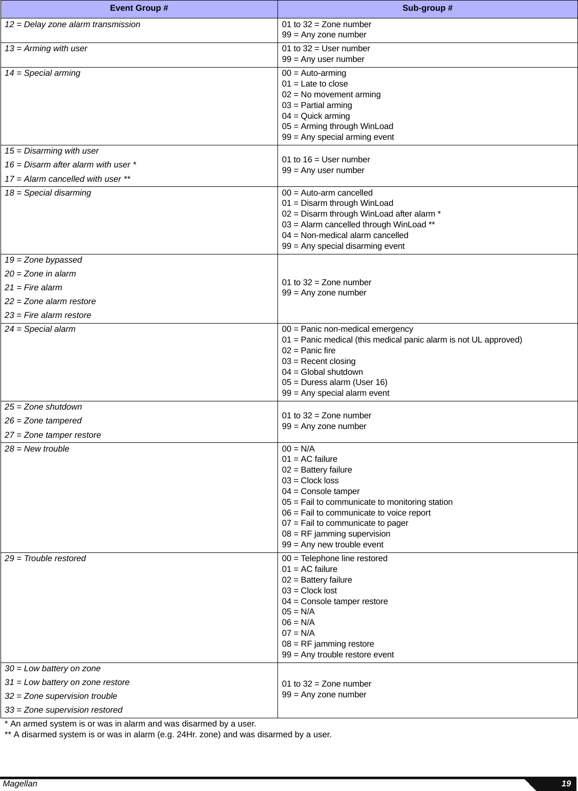
![18 Programming GuideAppendix 1: PGM Event TableEvent Group # Sub-group #00 = Zone closed 01 to 32 = Zone number99 = Any zone number01 = Zone opened02 = System status 00 = N/A01 = N/A02 = Silent alarm03 = Buzzer alarm04 = Steady alarm05 = Pulsed alarm06 = Strobe07 = Siren stopped08 = Squawk ON*09 = Squawk OFF*10 = Ground start11 = System disarmed12 = System armed13 = Entry delay engaged99 = Any system status event03 = Bell status 00 = Bell OFF01 = Bell ON02 = Bell Squawk Arm03 = Bell Squawk Disarm04 = Future use Future use05 = Non-reportable event 00 = Telephone line trouble01 = Future use02 = Arm with no entry delay03 = Arm in Stay mode04 = Arm in Force mode05 = Full arm when armed in Stay mode06 = PC fail to communicate07 = Future use08 = Future use05 = Non-reportable event (cont.) 09 = Doorbell 1 battery trouble10 = Doorbell 1 battery trouble restore11 = Doorbell 2 battery trouble12 = Doorbell 2 battery trouble restore13 = Utility Key 1 pressed (keys [1] and [9] from the center keypad)14 = Utility Key 2 pressed (keys [2] and [10] from the center keypad)15 = Utility Key 3 pressed (keys [3] and [11] from the center keypad)16 = Utility Key 4 pressed (keys [4] and [12] from the center keypad)17 = Utility Key 5 pressed (keys [5] and [13] from the center keypad)18 = Utility Key 6 pressed (keys [6] and [14] from the center keypad)19 = Utility Key 7 pressed (keys [7] and [15] from the center keypad)20 = Utility Key 8 pressed (keys [8] and [16] from the center keypad)21 = User remote access granted (MG-6160 only)22 = User remote access denied (MG-6160 only)23 = Tamper generated alarm24 = Supervision loss generated alarm99 = Any non-reportable event06 = Remote access 01 to 16 = User number99 = Any user number07 = PGM activation (Remote control button option “B”; see page 5)08 = PGM activation (Remote control button option “C”; see page 5)09 = Cold Start zone 01 to 32 = Zone number99 = Any zone number10 = Future use Future use11 = Smoke Maintenance signal 01 to 32 = Zone number99 = Any zone number* Squawk ON/OFF is similar to Bell ON/OFF except it follows the arming/disarming even if section [093] option [3] is disabled (no bell squawk when arming/disarming with remote control). These 2 events are used to activate/deactivate a light, strobe, or any other PGM with squawk activation/deactivation capabilities.](https://usermanual.wiki/Paradox-Security-Systems/MG6130.User-Manual-2/User-Guide-819070-Page-18.png)
![26 Programming GuideConnecting Magellan to WinLoadFigure 14: Connecting Magellan to WinLoadConnecting a Paradox Memory Key (PMC-4)Figure 15: Connecting a Paradox Memory Key (PMC-4)Back view of the Magellan console.Computer containing WinLoad software4- to 10-pin cable(supplied with the 306 Adapter)306 Adapter4-pin connector cableStandard DB-9 cable (9-pin serial cable)Back view of the Magellan console.Jumper ON:Read from and/or write to memory keyJumper OFF:Write protected (Read from the memory key only)PMC-4Download Data to Destination ConsoleTo download the data of a memory key into a console:1. Remove power from the Magellan console (AC and battery) and connect the memory key to the 5-pin connector on the left side of the back of the console as shown above.2. Re-apply both AC and battery power to the console.3. Press the [OK] key and Magellan will begin downloading the data from the memory key.Copy Data to Memory Key from Source ConsoleTo copy the contents of a console into the memory key.1. Remove power from the Magellan console (AC and battery) and connect the memory key to the 5-pin connector on the left side of the back of the console as shown above. Re-apply both AC and battery power to the console.2. Press the [NEXT] key and then the [OK] key. Magellan will begin copying its data into the memory key.The installer code of the Magellan console used to download data to the memory key must be the same installer code programmed in the Magellan console that is to download the contents from the same memory key. If the installer codes do not match, the contents of the memory key cannot be downloaded into the receiving console.Example: The contents of the Magellan console A will be copied into memory key B. The installer code for console A is 111111. In order to download the contents of memory key B into the Magellan console C, the installer code programmed in console C must also be 111111.](https://usermanual.wiki/Paradox-Security-Systems/MG6130.User-Manual-2/User-Guide-819070-Page-26.png)
![30 Programming GuideAppendix 5: Automatic Report Code ListSystem Event Default Contact ID Report Codewhen using sections [790] to [795] Default SIA Report Codewhen using sections [790] to [795]Arming with Master Code (##) 3 4A1 - Close by user CL - Closing ReportArming with User Code (##) 3 4A1 - Close by user CL - Closing ReportArming with Keyswitch (##) 3 4A9 - Keyswitch Close CS - Closing KeyswitchAuto Arming 3 4A3 - Automatic Close CA - Automatic ClosingArm with PC software 3 4A7 - Remote arm/disarm CL - Closing ReportLate To Close 3 4A4 - Late to Close OT - Late to CloseNo Movement 3 4A4 - Late to Close NA - No ActivityPartial arming 1 574 - Group bypass CG - Close AreaQuick arming 3 408 - Quick arm CL - Closing ReportClosing Delinquency 1 654 - System Inactivity CD - System InactivityDisarm with Master Code (##) 1 4A1 - Open by user OP - Opening ReportDisarm with User Code (##) 1 4A1 - Open by user OP - Opening ReportDisarm with Keyswitch (##) 1 4A9 - Keyswitch Open OS - Opening KeyswitchDisarm after alarm* with Master Code (##) 1 4A1 - Open by user OP - Opening ReportDisarm after alarm* with User Code (##) 1 4A1 - Open by user OP - Opening ReportDisarm after alarm* with Keyswitch (##) 1 4A1 - Keyswitch Open OS - Opening KeyswitchCancel alarm** with Master Code (##) 1 4A6 - Open by user OR - Disarm from AlarmCancel alarm** with User Code (##) 1 4A6 - Open by user OR - Disarm from AlarmCancel alarm** with Keyswitch (##) 1 4A6 - Keyswitch Open OS - Opening KeyswitchAuto Arming Cancellation 1 4A5 - Deferred Open/Close CE - Closing ExtendDisarm with PC software 1 4A7 - Remote arm/disarm OP - Opening ReportDisarm after an alarm with PC software 1 4A7 - Remote arm/disarm OR - Disarm From AlarmQuick disarm 1 408 - Quick disarm OP - Opening ReportZone Bypassed (##) 1 57A - Zone bypass UB - Untyped Zone BypassZone alarm (##) 1 13A - Burglary Alarm BA - Burglary AlarmFire alarm (##) 1 11A - Fire alarm FA - Fire AlarmZone alarm restore (##) 3 13A - Burglary Alarm Restore BH - Burglary Alarm RestoreFire alarm restore (##) 3 11A - Fire alarm Restore FH - Fire Alarm RestorePanic 1 - Emergency 1 12A - Panic alarm PA - Panic AlarmPanic 2 - Medical 1 1AA - Medical alarm MA - Medical AlarmPanic 3 - Fire 1 115 - Pull Station FA - Fire AlarmRecent closing 3 4AA - Open/Close CR - Recent ClosingGlobal zone shutdown 1 574 - Group bypass CG - Close AreaDuress alarm 1 121 - Duress HA - Hold-up AlarmZone shutdown (##) 1 57A - Zone bypass UB - Untyped Zone BypassZone tampered (##) 1 144 - Sensor tamper TA - Tamper AlarmZone tamper restore (##) 3 144 - Sensor tamper restore TR - Tamper RestoralKeypad Lockout 1 421 - Access denied JA - User Code Tamper* An armed system is or was in alarm and was disarmed by a user.** A disarmed system is or was in alarm (e.g. 24Hr. zone) and was disarmed by a user.](https://usermanual.wiki/Paradox-Security-Systems/MG6130.User-Manual-2/User-Guide-819070-Page-30.png)
![Magellan 31AC Failure 1 3A1 - AC loss AT - AC TroubleBattery Failure 1 3A9 - Battery test failure YT - System Battery TroubleAuxiliary supply trouble 1 3AA - System trouble YP - Power Supply TroubleBell output current limit 1 321 - Bell 1 YA - Bell FaultBell absent 1 321 - Bell 1 YA - Bell FaultClock lost 1 626 - Time/Date inaccurate JT - Time ChangedFire loop trouble 1 373 - Fire trouble FT - Fire TroubleTLM trouble restore 3 351 - Telco 1 fault restore LR - Phone Line restoralAC Failure restore 3 3A1 - AC loss restore AR - AC RestoralBattery Failure restore 3 3A9 - Battery test restore YR - System Battery RestoralAuxiliary supply trouble restore 3 3AA - System trouble restore YQ - Power Supply restoredBell output current limit restore 3 321 - Bell 1 restore YH - Bell RestoredBell absent restore 3 321 - Bell 1 restore YH - Bell RestoredClock programmed 3 625 - Time/Date Reset JT - Time ChangedFire loop trouble restore 3 373 - Fire trouble restore FJ - Fire Trouble RestoreCombus fault 1 333 - Expansion module failure ET - Expansion TroubleModule tamper 1 145 - Expansion module tamper TA - Tamper AlarmModule ROM_RAM_error 1 3A4 - Rom checksum bad YF - Parameter Checksum FailModule TLM trouble 1 352 - Telco 2 fault LT - Phone Line troubleModule fail to communicate to monitoring station. 1 354 - Fail to communicate YC - Communication FailsPrinter fault 1 336 - Local printer failure VT - Printer TroubleModule AC Failure 1 3A1 - AC loss AT - AC TroubleModule battery failure 1 3A9 - Battery test failure YT - System Battery TroubleModule Auxiliary supply trouble 1 3AA - System trouble YP - Power Supply TroubleBus fault restore 3 333 - Expansion module failure restore ER - Expansion RestoralModule tamper restore 3 145 - Expansion module tamper restore TR - Tamper RestoralModule ROM_RAM_error restore 3 3A4 - Rom checksum bad restore YG - Parameter ChangedModule TLM restore 3 352 - Telco 2 fault restore LR - Phone Line RestoralPrinter fault restore 3 336 - Local printer failure restore VR - Printer RestoreModule AC restore 3 3A1 - AC loss restore AR - AC RestoralModule battery restore 3 3A9 - Battery test failure restore YR - System Battery RestoralModule Auxiliary supply restore 3 3AA - System trouble restore YQ - Power Supply RestoredFail to communicate with monitoring station 1 354 - Fail to communicate YC - Communication FailsModule RF low battery 1 384 - RF transmitter low battery XT - Transmitter Battery TroubleModule RF battery restore 3 384 - RF transmitter battery restore XR - Transmitter Battery RestoralModule RF supervision trouble 1 381 - Loss of supervision - RF US - Untype Zone SupervisionModule RF supervision restore 3 381 - Supervision restore - RF UR - Untyped Zone RestoralCold Start 1 3A8 - System shutdown RR - Power UpWarm Start 1 3A5 - System reset YW - Watchdog ResetTest Report engaged 1 6A2 - Periodic test report TX - Test ReportPC software communication finished 1 412 - Successful - download access RS - Remote Program SuccessInstaller on site 1 627 - Program mode Entry LB - Local ProgramInstaller programming finished 1 628 - Program mode Exit LS - Local Program SuccessSystem Event Default Contact ID Report Codewhen using sections [790] to [795] Default SIA Report Codewhen using sections [790] to [795]](https://usermanual.wiki/Paradox-Security-Systems/MG6130.User-Manual-2/User-Guide-819070-Page-31.png)