Parente Fireworks Srl FIREMASTER4KR FIREMASTER IV REMOTE UNIT User Manual SISTEMA FIREMASTER III
Parente Fireworks Srl FIREMASTER IV REMOTE UNIT SISTEMA FIREMASTER III
Contents
Users Manual II

FIREMASTER IV "
MillenniumThree
" radio shooting system User’s manual
SYSTEM FIREMASTER IV
"Millennium Three"
RADIO-CONTROLLED SYSTEM FOR REMOTE SHOOTING OF
PYROTECHNIC SHOWS
USER’S MANUAL
CONTENTS
Paragraph Page
1. Base Station - Control Unit TX5000 3
1.1 Front panel diagram 3
1.1.1 Front-panel commands description 3
1.2.1 Instrument case and connector description 6
1.3 Operation 7
1.4 Base Station TX5000 usage procedure 7
1.5 "SHOW MANAGEMENT" mask description 8
1.6 "TOOLS" mask 10
1.7 "SYSTEM SETUP" Icon 11
1.8 "OLD UNITS SETUP" Icon 12
1.9 "TONE GENERATOR" Icon 15
1.10 “TONE GENERATOR” TESTING 16
1.11 SMPTE TEST ICON 18
1.12 MIDI TEST ICON 20
2. "TESTING" Icon 21
2.1 "TEST LINE" Icon 21
2.1.1 Modify the single line parameters 26
2.2 Notes about the usage of the numeric keypad 28
2.3 "TEST UNIT" Icon 30
2.3.1 Data modification 34
2.3.2 How to remove all timed sequences from the same remote unit 36
2.4 “IMPORT/EXPORT” Icon 37
2.4.1 How to compile a pyrotechnic show on a PC 38
2.4.2 How to download the show file to the TX5000 Unit 39
2.4.3 EDIT and SAVE the downloaded show data 41
2.4.4 The “EDITING” menu 43
2.5 The “UNITS PROGRAM” menu 44
2.5.1 “SHOW VERIFY” mask 45
2.5.2 Error messages 46
3. "FIRE" function 48
3.1 Foreword 48
3.2 "FIRE" mask 49
3.3 Firing options 51
3.3.1 MANUAL Mode 52
3.3.2 "MUSIC" Mode 52
3.3.3 "MANUAL SHOW" Mode 54
3.3.4 " PYROMUSICAL SHOW" Mode 55
1

FIREMASTER IV "
MillenniumThree
" radio shooting system User’s manual
3.3.5 " AUTOMATIC SHOW ” Mode 55
3.3.6 Options in “SHOW” mode 58
3.3.7 Operation Notes when in "FIRE MODE" 59
4. REMOTE UNITS RX48 (Receivers) 60
4.1 Front-panel diagram 60
4.2 Case description 61
4.3 Commands description 61
4.4 LED displays description 63
4.5 General description 66
4.6 Power-on procedure 67
4.7 Units Field usage 68
4.7.1 Protection 68
4.7.2 Antennas 71
4.8 Connections 73
4.8.1 Firing lines 73
4.8.2 Coaxial cable connection 74
4.8.3 RS-485 77
4.8.4 RS-232 79
5. BPK48-A Battery Pack 81
5.1 Case and Front-panel diagram 81
5.2 General Description 84
5.2.1 Use 84
5.3 Operation description 85
5.3.1 TEST 85
5.3.2 TEST (Unit connected to mains) 85
5.3.3 TEST conditions 85
5.3.4 Charge 86
5.3.5 Error conditions listing 87
5.4 Batteries 88
5.5 Internal batteries replacement 90
6.0 General safety rules and warnings 93
7.0 Technical specifications 96
7.1 Base Unit TX5000 technical specifications 96
7.2 RX48 TWIN Remote Units technical specifications 96
7.3 BPK-48A Battery Pack technical specifications 97
8. Certifications 98
8.1 Warranty 99
8.2 Declaration of conformity 100
8.2.1 Declaration 100
8.2.2 Remark s 101
2
FIREMASTER IV "
MillenniumThree
" radio shooting system User’s manual
1. COMMAND UNIT MODEL TX 5000
BASE STATION MODEL TX5000
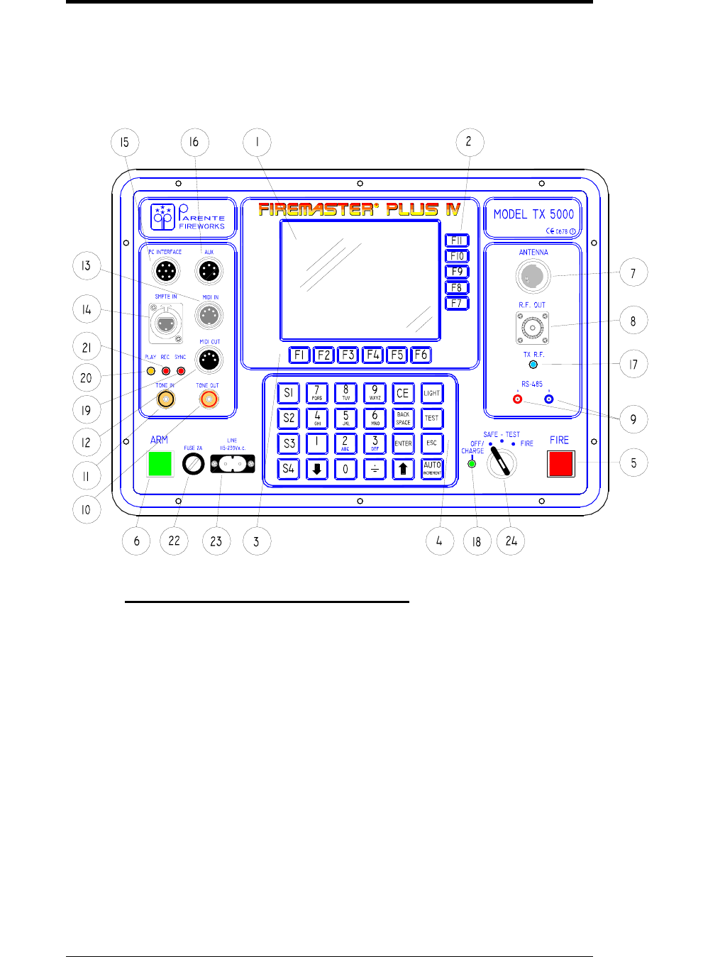
1.1 FRONT-PANEL DIAGRAM
1.1.1 Front-panel commands description
1. LCD graphic screen with back-lighting. B/W type, high graphic
resolution ( 320x240 pixels -1/4 VGA).
2. FUNCTION Keys F7 - F11 - the specific function of these keys varies
with the mask actually displayed on the screen and it is described by
means of a specific graphic icon placed near the key.
3. FUNCTION Keys F1 - F6 - the specific function of these keys varies with
the mask actually displayed on the screen and it is described by means of a
specific graphic icon placed near the key.
4. Numeric keypad: it allows the entry and modification of the numeric
parameters inside the functions.
3

FIREMASTER IV "
MillenniumThree
" radio shooting system User’s manual
5. FIRE Pushbutton – When pressed together with the ARM key, starts
immediately the firing of all lines with the sequence number actually
displayed. ARM and FIRE buttons, if pressed alone, have NO EFFECT.
When a sequence has been fired, in order to step to the next one (or to
allow the auto-increment function to do it automatically), it will be
necessary to release BOTH buttons. ARM or FIRE buttons, when the
keyswitch is SAFE/TEST position, can be used INDIFFERENTLY to
trigger a SYNCHRONISM tone output (see a more detailed description at
chapter 1.6 “Tools Mask”).
6. ARM Pushbutton – When pressed, the system (if the selector key is on
the FIRE position), is ARMED and ready to fire.
7. Main Antenna. Turret for the attachment of the whip antenna
supplied with the instrument. The antenna resonates at λ/4 on
40,675MHz. NOTE: use the original antenna only.
8. R.F. OUTPUT – “UHF” coaxial connector. Output for test purposes
only. It is capacitively-coupled and allows to monitor the output R.F.
signal with an oscilloscope or a frequency counter.
9. RS-485 standard SERIAL Port. 2mm plug connectors. This port is used
to connect the base Unit TX5000 to the Remote Units RX48 when a
CABLE CONNECTION is required in place of the standard RADIO link
(or to implement a mixed-type connection: CABLE+RADIO). The
connection wiring requires TWO WIRES ONLY: A and B connections
MUST be respected (i.e.: pin A of TX5000 must be connected to ALL pins
A of the RX-48 units and pin B to ALL corresponding pins B of the RX-
48 units. Only the LAST RX48 unit must be LOADED with a terminating
120ohm resistor placed between A and B.
10. TONE OUT: RCA-type connector (red). Generates an audio synchronism
tone: it can be recorded along with the musical base in order to
synchronize the FIRE command.
11. TONE IN: RCA-type connector (black). Accepts an AUDIO input
synchronism coded signal to synchronize the FIRE command with the
musical base during the show.
12. MIDI OUT: 5-pole (180°) female DIN connector. It is a standard MIDI
output replicating exactly the signals present at connector 13 (MIDI IN). It
can be used to pass the MIDI signal to other units sharing the same
synchronism.
13. MIDI IN: 5-pole (180°) male DIN connector. It is a standard MIDI input
with total opto-insulation of the incoming signal.
14. SMPTE IN: 3-pole “XLR” female connector. Accepts a standard
SMPTE/EBU timecode signal. It can be used to synchronize the firing
sequence to an external timing source.
4

FIREMASTER IV "
MillenniumThree
" radio shooting system User’s manual
15. PC INTERFACE: 7-pole female DIN connector. It can be used for a
direct connection of the TX5000 to any RS-232 serial port of a standard
PC or video terminal. Two SPECIAL cables are supplied for this
connection:
a) BLACK CABLE: to be used for STANDARD OPERATION with the
SHOWLOADER® program in order to download the show data from the
PC.
b) RED CABLE: to be used for INTERNAL FIRMWARE UPGRADES
ONLY. It is normally supplied separately along with the firmware patches
or upgrades when available. This cable must be used uniquely for this
purpose with great care and following strictly the operating instructions
supplied along with the firmware to be installed.
16. AUX: 5-pole (240°) female DIN connector. It can be used to plug directly
the AUXILIARY PANEL LIGHT (constant-current supply) or to access
directly the ARM and FIRE buttons contacts (if required by other external
equipments).
17. R.F. Carrier indicator. When this blue LED turns ON, the radio
transmitter is ACTIVE and sending a message to the remote units.
18. CHARGE/FAULT indicator. This is a three-color LED: when the line
cord is plugged on the TX5000 for battery re-charge, the battery is first
tested during 60 seconds and the LED is lit yellow. After the test period, if
the battery has been found between the limits for a normal charge, then the
LED turns green and the charge period (12 hours) starts. If otherwise the
battery should be damaged (and thus the charge not possible), then the
LED will turn RED.
19. SYNC indicator: red LED. It is turned ON when the audio synchronism
feature has been enabled (“tools” menu) and whenever a valid audio sync
signal is received at TONE IN connector (11).
20. REC indicator: red LED. It turns ON when the audio synchronism
feature has been enabled (“tools” menu) and the RECORDING mode
selected.
21. PLAY indicator: yellow LED. It turns ON when the audio synchronism
feature has been enabled (“tools” menu) and the PLAY mode selected.
22. FUSE 2A: protection fuse in series with the supply battery. Fast-blow
type 20x5mm 2A – 250V
23. LINE 110/240Va.c. two-pole mains receptacle. It accepts standard 2-pole
cables to be plugged directly into the mains receptacle for battery charging.
The internal supply accepts automatically voltages from 110V up to 240V
a.c. 50 or 60Hz without need for range switching.
NOTE: Since the TX-5000 Unit IS NOT PROVIDED with a LINE SWITCH, the Unit
itself, during the charging process, must be suitably placed in order to allow the easy
removal of the LINE CORD at any moment, in case of emergency.
5
FIREMASTER IV "
MillenniumThree
" radio shooting system User’s manual
24. Selector Key: 3-position switch with safety key
OFF/CHARGE – system switched OFF. If the TX5000 is connected to
the main when the switch is in this position, the battery charging
sequence will start immediately.
SAFE/TEST – safe operation position: in this mode it will be possible
to test the lines of all field units and to check/modify the sequences
programming WITHOUT ANY RISK TO activate a FIRE condition.
FIRE – firing position: in this mode the show parameters cannot be
changed anymore, but it will be only possible to address the needed
sequence and to FIRE it.
NOTE: even if apparently possible, the operation in SAFE or FIRE position
with the mains cord connected, IS NOT RECOMMENDED.
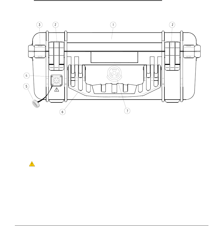
1.2.1 Instrument case and connector description
1. IP67 Ultra High Impact Copolymer Polypropylene case. 40.6 x 33 x 17.4 mm
2. Double-step latches
3. Stainless steel reinforced padlock protector
4. Waterproof 7-pole DIN connector for external emergency battery.
5. Protection cap for the DIN connector.
6. Fold-down and rubberized handle
7. Automatic pressure equalization valve
6
FIREMASTER IV "
MillenniumThree
" radio shooting system User’s manual
1.3 Operation
1.4 Base Station TX5000 usage procedure
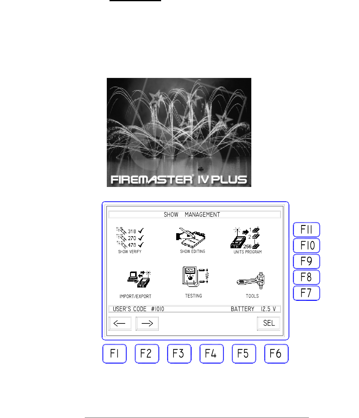
Turn the key selector on TEST/SAFE position: the display light will
turn on and the graphic logo "FIREMASTER IV PLUS" will appear.
The logo will remain 10 seconds and the main menu mask will be
automatically displayed. Pressing any key before the 10 seconds period
is elapsed, the main menu mask will be immediately displayed.
7
FIREMASTER IV "
MillenniumThree
" radio shooting system User’s manual
NOTE the display back lighting is timed and automatically turns off
after 30 seconds. Pressing any key it will turn on again immediately
The MAIN MENU mask SHOW MANAGEMENT contains 6 icons
for every operation mode:
The selection of the proper icon is made with F1 and F2 keys: the six
icons will be evidenced in sequence. The F6 "SEL" key "opens" the
highlighted icon. Inside this mask, all other keys are INACTIVE.
1.5. "SHOW MANAGEMENT" Mask description
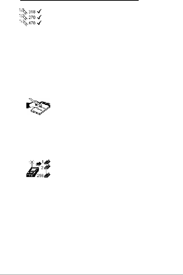
"SHOW VERIFY" Icon. It can be used only if one is operating
using a show created externally on a PC and already loaded on the
TX5000 Base Unit memory. It allows carrying out in a completely
automatic mode the query of all remote units active on the field and
to perform a complete verify of the data inside each Unit with the
data of the whole show stored inside the TX5000 Base Unit. All data
discrepancies will be reported in order to allow a fast and effective
correcting action.
"SHOW EDITING" Icon. It can be used only if one is
operating using a show created externally on a PC and already
loaded on the TX5000 Base Unit memory. It allows to manually
modify the parameters of the internally-stored show.
"UNITS PROGRAM" Icon. It can be used only if one is
operating using a show created externally on a PC and already
loaded on the TX5000 Base Unit memory. It allows to transfer a
program (a show) from the Base Unit memory to the remote
units on field. The remote units will be automatically "called" in
sequence and the base Unit will provide to download for each
unit the needed programming parameters. Should any unit fail to
reply, the "download" process will be halted and an error
message will be displayed.
8
FIREMASTER IV "
MillenniumThree
" radio shooting system User’s manual
"IMPORT/EXPORT" Icon. It can be used only if one is
operating using a show created externally on a PC. It allows to
transfer the show data created on an external PC to the memory
of the Base Unit TX5000 and vice-versa. For all data transfers
the serial port RS-232 will be used.
"TESTING" Icon. This icon allows access to the most
important functions of the FIREMASTER III SYSTEM. By
means of these functions the shooter can verify, modify and
program all the remote units creating a complete show on the
field or at the company. Unlike a show created on a PC and
loaded on the base Unit TX5000 (it remains permanently stored
in memory), all data loaded "manually" on the RX48 remote
units with these functions, will remain stored on the memory of
each remote unit only. It will be then impossible any automatic
function of verify of the whole show. The verify must be
performed "manually" unit by unit, checking the returned data
with a paper copy of the show program.
"TOOLS" Icon. It gives access to several "auxiliary" functions
of the FIREMASTER SYSTEM. In particular:
- the data transmission mode (CABLE or RADIO)
- definition of a specific receiver (RX-24) as "old unit"
(FIREMASTER II) in order to obtain the full compatibility with
the existing units of the previous generation
- the management of the music synchronization system (tone
generation).
- The management of SMPTE and MIDI time code formats for
automatic firing under external control.
9
The lower data bar (always present in all masks) shows the following data:
the user's code (user's # ) and the internal system battery voltage. The
“user's #” is the system owner personal code number (4 digits). Every user
has a different code, generated at the moment of the first purchase of the
System. This code must match with the corresponding one on all Remote
Units. This prevents the risk of cross-interference when two or more
FIREMASTER SYSTEMS are used at the same time by different
companies on the same site. The personal code also protects against any
malicious competitor that, using his TX5000 Unit, could try to
intentionally interfere with the regular show execution.
FIREMASTER IV "
MillenniumThree
" radio shooting system User’s manual
10
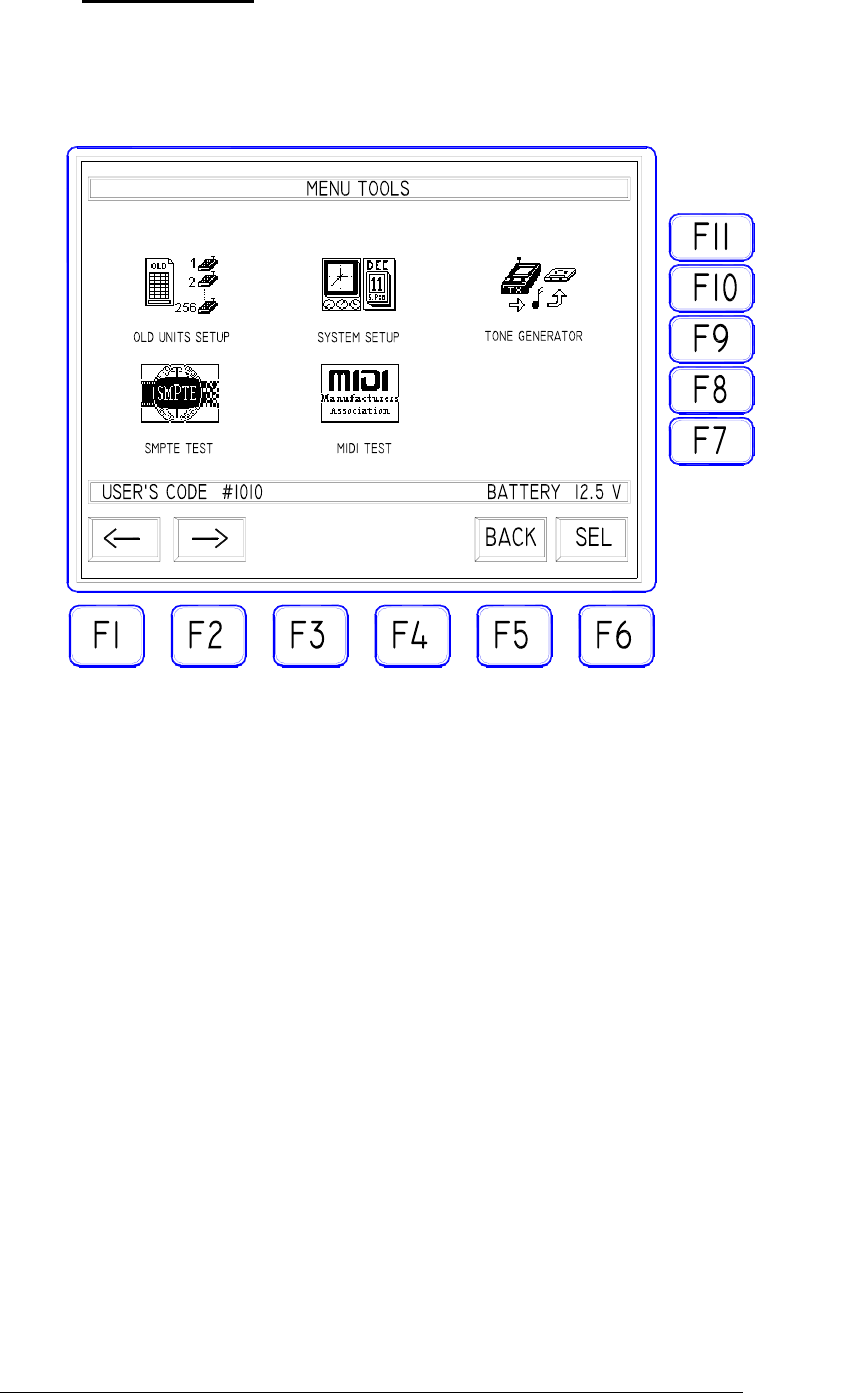
1.6. "TOOLS" Mask
Selecting this icon, the sub-menu of the auxiliary functions and
system setup is accessed.
The Icon selection is made by means of the F1 and F2 keys allowing
to highlight in sequence the three available icons. with F6 "SEL" key
the selected icon will be activated. With F5 "BACK" key the main
menu is selected again. Inside this mask all other function keys are
disabled.
FIREMASTER IV "
MillenniumThree
" radio shooting system User’s manual
11
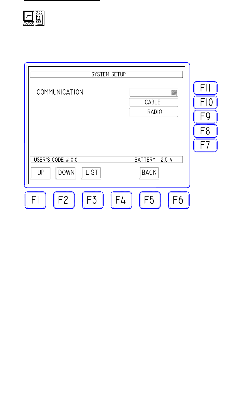
1.7. "SYSTEM SETUP" Icon
Selecting this icon allows to select one of the two communication
modes of TX5000: CABLE or RADIO
TRANSMISSION MODE SELECTION: with "UP" and "DOWN"
keys (F1 and F2), select the "COMMUNICATION" bar, press the
"LIST" key (F3) to open the pop-down showing the two possible
options "RADIO" or "CABLE". Select with "UP" and "DOWN"
keys the needed mode and confirm using ENTER. The "BACK" key
allows to exit the mask returning to the previous menu.
"RADIO" MODE: only the data relative to the FIRE COMMANDS
will be sent to the remote units both by radio link and cable (using
the RS-485 port). The operator is thus allowed to use a "mixed" link
mode connecting by cable the units that, due to critical conditions of
radio propagation, shouldn't receive correctly the radio signals. The
remaining units NOT connected by cable, will continue to operate
using the RADIO link.
"CABLE" MODE: only the data relative to the FIRE
COMMANDS, will be sent to the remote units using THE CABLE
CONNECTION ONLY (RS-485 port). The RADIO transmitter of
the Base Station will be completely DISABLED during this
operation mode and thus ALL REMOTE UNITS must be connected

FIREMASTER IV "
MillenniumThree
" radio shooting system User’s manual
together and with the Base Station, using a two-wire line and the RS-
485 ports present on all units for this purpose.
One should use this operating mode only if the radio propagation
conditions are really poor (due to the particular ground
configuration or to the presence of natural or artificial obstacles)
and the received signal strength should be below 20dBµV, or
when special security dispositions or local laws should forbid
THE USE OF RADIO TRANSMISSIONS.
WARNING!: the "CABLE" operating mode can be used ONLY
to issue the FIRE commands (show execution). For any other
TEST or PROGRAMMING operation (key switch on "TEST-
SAFE" position), the "RADIO" mode MUST be used instead!
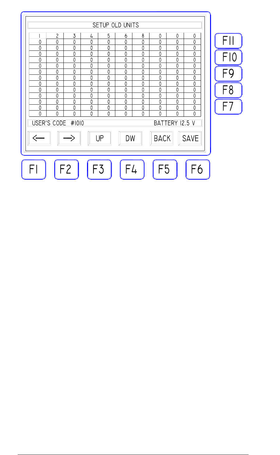
1.8. "OLD UNITS SETUP" Icon
The FIREMASTER IV SYSTEM has been designed in order to
easily implement the system expansion for all customers already
using a previous-generation FIREMASTER SYSTEM
(FIREMASTER II and FIREMASTER II-T). It will be then possible
to use a mixed system composed by "new" and "old" units.
Four different cases exist:
1- TX5000 BASE UNIT and RX48 Remote Units (FIREMASTER
IV): the whole system is of "new generation" type, all new
features are normally available and the present icon can be
completely disregarded (all data must be set to ZERO).
2- TX1000 Base Unit and RX24-B (FIREMASTER III) or RX48
(Firemaster IV) remote units: the whole system will operate
correctly but, due to use an "old generation" Base Station, all
new functions will be NOT AVAILABLE. The whole system
will operate exactly as being composed by "old generation"
Remote Units (RX24-A FIREMASTER II). Because all new
commands and functions cannot be activated from the "old"
transmitter, TX5000 settings is of NO CONCERN.
3- TX2000 Base Unit (Firemaster III) and any combination of
Remote Units (RX24, RX24-B and RX48). In the latter case, in
order to avoid errors due to the reception of "new" commands
(executable only by the "new generation" Units) by the "old"
type Units (RX24 Firemaster II), it will be necessary to insert in
the "boxes" displayed in this mask, THE NUMBERS OF ALL
REMOTE UNITS of "old generation" type. The System will be
12
FIREMASTER IV "
MillenniumThree
" radio shooting system User’s manual
able to automatically recognize these units when the TEST or
PROGRAMMING signals are issued. PRACTICALLY: the User
will define once for all the "old generation" type Units and will
type the corresponding numbers in the cells of this mask.
4- TX5000 Base Unit and any combination of Remote Units
(RX24, RX24-B and RX48). As in the previous case it will be
necessary to specify the numbers for the RX24 units (Firemaster
II) eventually present. RX24-B (Firemaster III) units are
completely compatible with the new TX5000 Base unit and don’t
require any setup in this mask.
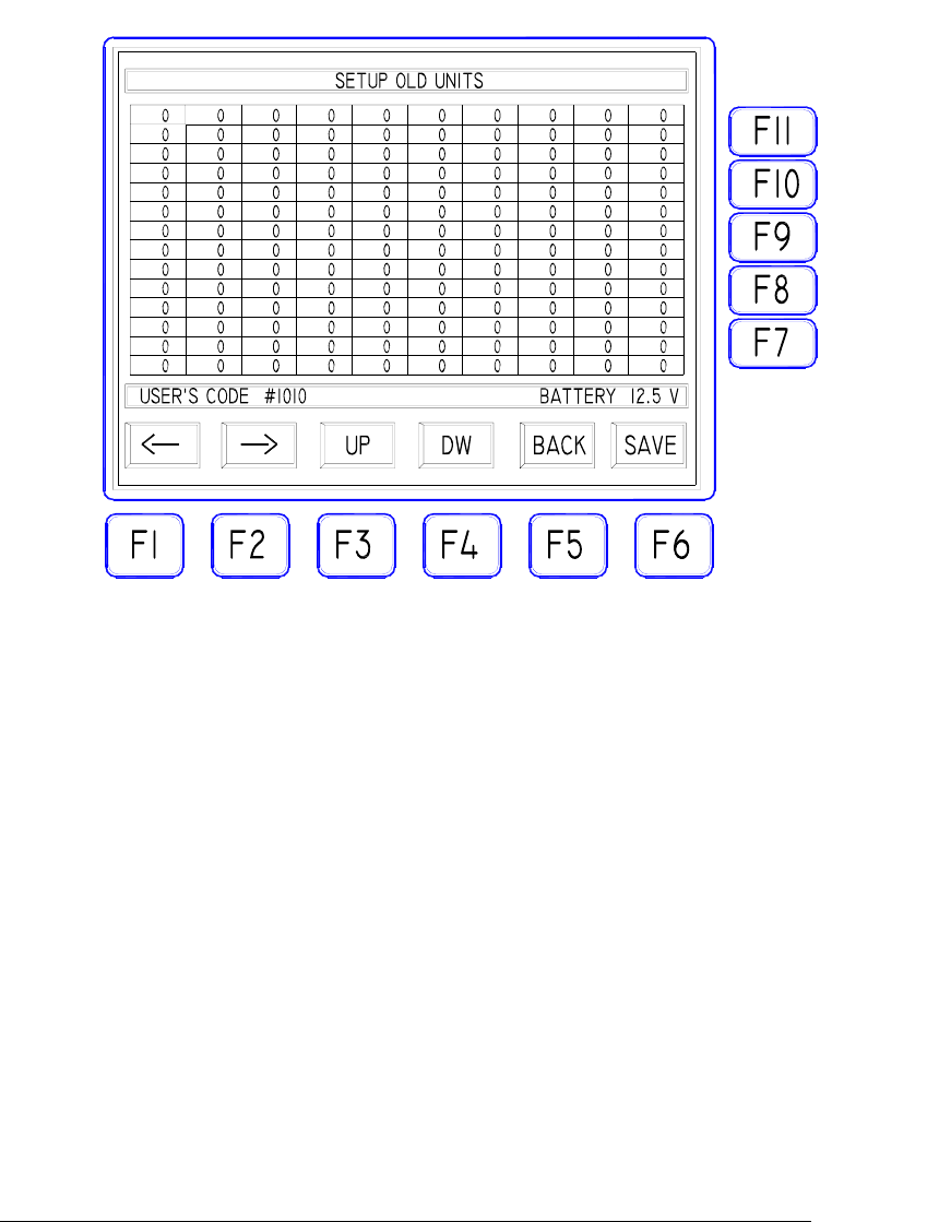
The numbers of the "old generation" type Units, can be inserted IN
ANY ORDER and IN ANY CELL among the 140 available. For an
obvious readability reason, it is suggested to proceed orderly starting
from the uppermost cell on the left. One should insert ONLY the
numbers of the FIREMASTER II "old generation" Remote Units
(RX24), leaving at ZERO all other cell values.
Just suppose an user already owing 8 "old generation" Units
numbered 1 to 8 and purchasing 10 more Units of "new generation"
(FIREMASTER III or FIREMASTER IV) numbered 9 to 18, plus
one Base Unit TX5000. In order to operate indifferently with all
Units and to completely take advantage from the resources of the
new system, he should set the "SETUP OLD UNITS" mask as
follows:
13
FIREMASTER IV "
MillenniumThree
" radio shooting system User’s manual
Once the numbers of the "old generation" type Units, will be correctly
entered, press the F6 "SAVE" key to confirm and leave the mask using F5
"BACK".
14
FIREMASTER IV "
MillenniumThree
" radio shooting system User’s manual
15
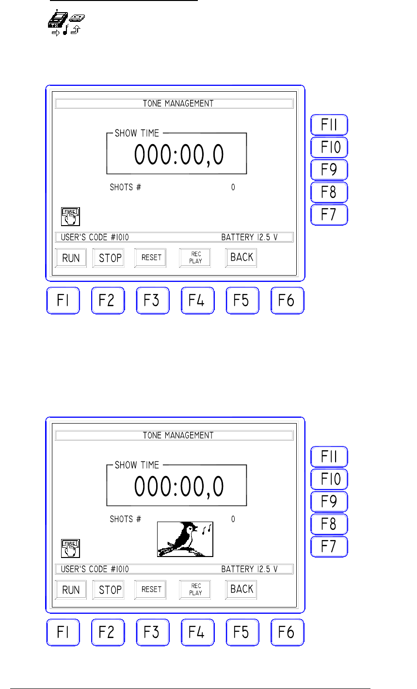
1.9. "TONE GENERATOR" Icon
Selecting this icon, one will access the function for the
GENERATION of a FIRE COMMAND coded as an audio tone
(AFSK) available to the "TONE OUT" connector.
This signal is intended to be recorded on the musical base in order to
obtain a synchronism with the accompanying music during the
pyromusical shows. (For more details, see the relative chapter).
Operating inside this mask, every time the "FIRE" key is activated, a
coded audio tone will be generated and this is marked by the icon
with the bird and a long buzzer sound.
FIREMASTER IV "
MillenniumThree
" radio shooting system User’s manual
When the "FIRE" key is pressed the first time (start of the show), the time
counter (SHOW TIME) starts to advance displaying minutes, seconds and
tenths of a second elapsed (up to 999minutes, 59 seconds and 9 tenths). At
any time the time counter can be STOPPED ("STOP" F2), RESET TO
ZERO ("RESET" F3) and RE-STARTED ("RUN" F1) using the relative
function keys. As usual the "BACK" key allows to exit the function and to
return to the previous mask.
NOTE: the time counter values are given for INDICATION PURPOSE
ONLY and can be used to help the operator to issue the synchronism tones
at the exact moment. THE TIME VALUES DISPLAYED ARE NOT
RECORDED nor doesn't have any effect on the functions of the Base Unit
TX5000.
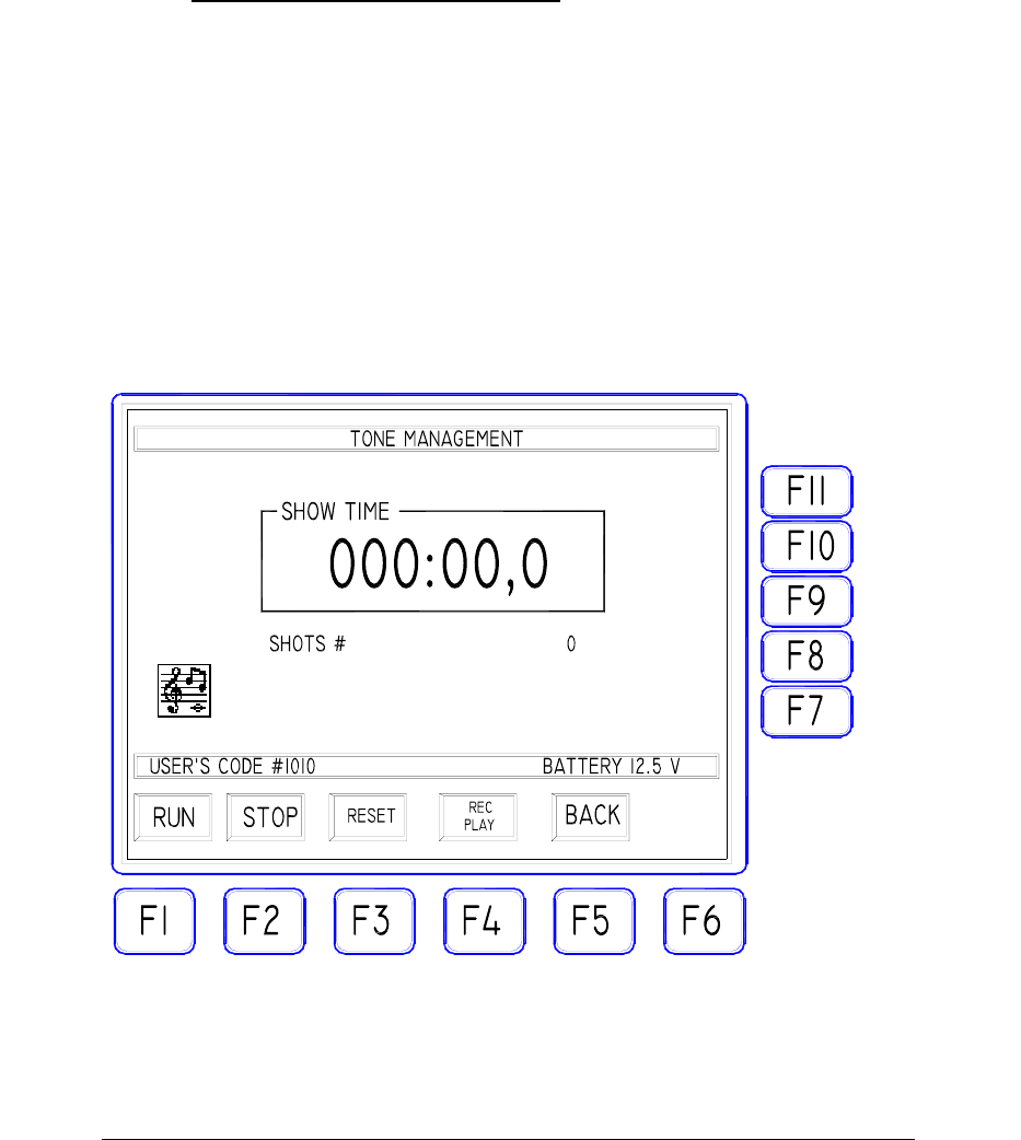
1.10. TONE GENERATOR TESTING
Connect the EXTERNAL audio equipment (PC sound card, tape, CD, etc.)
to the AUDIO IN connector on the front panel of your TX5000 with a
suitable RCA plug. The audio system will be set to reproduce a series of
synchronism “tones” previously recorded. The audio tones must be
sufficient to carry-out the test for at least 30 seconds. It is suggested to
record 30 tones spaced apart by at least one second.
Press the “toggle” key F4 to select the PLAY mode. The PLAY mode is
selected when the corresponding “PLAY” LED on the front-panel is ON
and the TONE MANAGEMENT MASK shows the following icon:
Start the external audio system: each time a valid audio tone is received, the
“bird” icon will be displayed along with a buzzer beep, the SYNC LED on
16

FIREMASTER IV "
MillenniumThree
" radio shooting system User’s manual
the front panel will flash and the “SHOT #” count on the LCD screen will
increase by one unit.
At the end of this test the “SHOT #” counter must display exactly the
number of audio tones received (30 in our example).
Should the counter value differ from the real number of tones received,
check one of the following probable causes:
- input audio level too low (it must be AT LEAST 0.5Vpp)
- input audio level too high (the maximum allowed is 5Vpp)
- connection cable or connectors problems
- audio tones not properly recorded (distortion or noise present
along with the useful signal).
Fix the problem and repeat the test until the value displayed by the counter
agree with the number of tones you have recorded.
17
FIREMASTER IV "
MillenniumThree
" radio shooting system User’s manual
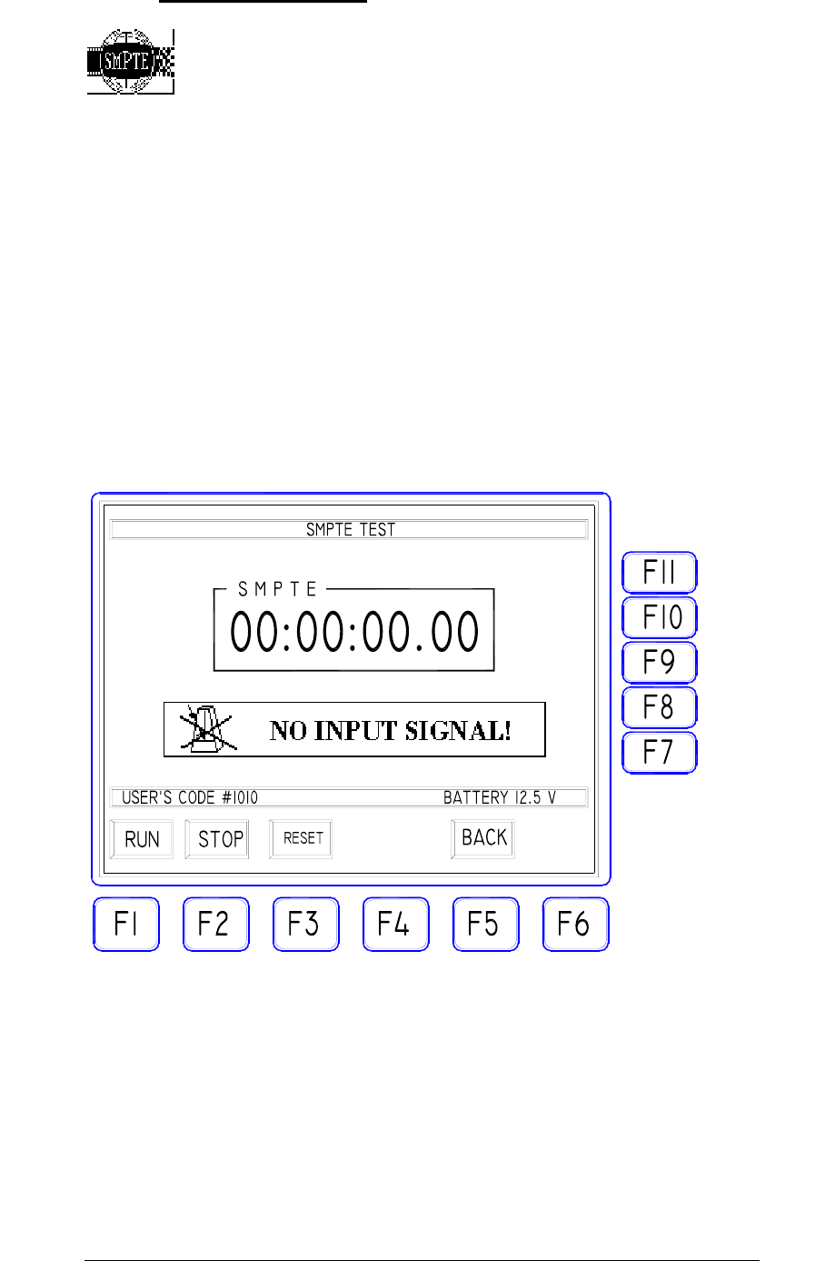
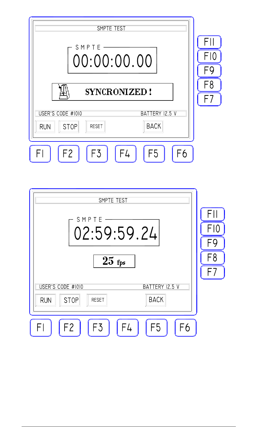
1.11. "SMPTE TEST" Icon
This menu allows TO TEST the performance and the signal level for the
SMPTE time code reference.
The SMPTE signal is usually distributed by the general audio management
system in order to give a common timing base to synchronize all
equipments.
The SYSTEM FIREMASTER IV is provided with a dedicated decoder
receiving this signal and using it to synchronize all firing activities with the
common time reference.
The SMPTE/EBU time code must be of LTC type (Lateral Time Code).
With no SMPTE input signal, the mask will show as follows:
When a valid SMPTE code is applied to the front-panel input and the RUN
key pressed, the system will start to decode the incoming signal and the
mask will display the “SYNCHRONIZED” message along with the type of
SMPTE decoded (24, 25, 30 fps, drop or no-drop). The counter will start
immediately to display the actual time code received (hours, minutes,
seconds, frames/second):
18
FIREMASTER IV "
MillenniumThree
" radio shooting system User’s manual
19

FIREMASTER IV "
MillenniumThree
" radio shooting system User’s manual
1.12. "MIDI TEST" Icon
The MIDI test window is exactly similar to the previous one for all
concerning the data displaying and general operation.
The MIDI TIMECODE signal must be connected to the MIDI IN connector
on the front-panel.
Note as the time information IS THE SAME for SMPTE and MIDI: only
the transmission protocol and the input/output circuitry changes between the
two methods.
The SYSTEM FIREMASTER TX5000 does implement MIDI /
TIMECODE decoding function only and doesn’t manage any other standard
MIDI commands.
20