Parente Fireworks Srl FIREMASTER4KR FIREMASTER IV REMOTE UNIT User Manual 2
Parente Fireworks Srl FIREMASTER IV REMOTE UNIT 2
Contents
Users Manual III
FIREMASTER IV "
MillenniumThree
" radio shooting system User’s manual
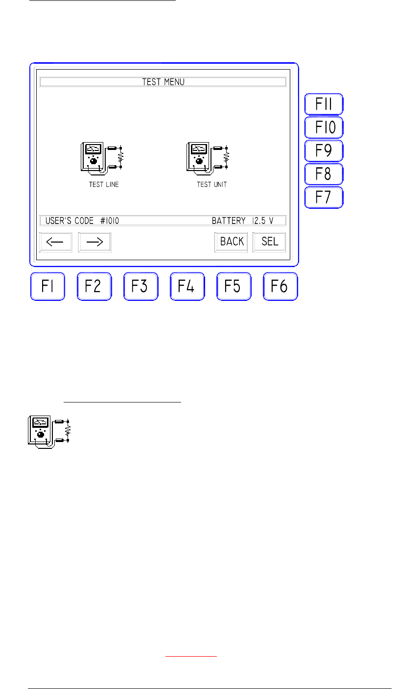
2 . "TESTING" ICON
This mask allows to select the functions for SET, MODIFY and CHECK all
parameters of the Remote Units active at the same moment.
Using keys F1 and F2, one can select one of the two possible operating modes:
"TEST LINE" and "TEST UNIT". With "SEL" F6 it will be open the mask
relative to the selected icon.
2.1
"TEST LINE" ICON
This icon selects the menu of SINGLE LINE TEST. This operating mode is the
same used in the previous version FIREMASTER II and FIREMASTER III: it is
possible to "call" one line at the time and the following parameters will be returned:
the number of the Remote Unit containing this line, the sequence of that line, the
ohmic resistance of the line, the batteries voltages, the level of the radio signals both
received and transmitted and, if the sequence is of "timed" type, also the time value.
The sequence and time parameters can be modified at any time and the
variations will take place immediately being stored in the memory of the remote
unit.
NOTE: any modification made with this function, WILL BE NOT COPYED in
the memory of the Base Unit and thus the "SHOW" data eventually downloaded
from a PC with the serial line, will REMAIN UNCHANGED. The user must have
well clear in mind as, if the show has been created on a PC using a commercial
program of show management and then loaded in memory, it will be mandatory to
verify, test and modify it using exclusively the functions of "SHOW EDITING",
"SHOW VERIFY", "IMPORT/EXPORT" and "UNITS PROGRAM" providing
21
FIREMASTER IV "
MillenniumThree
" radio shooting system User’s manual
a constant parallelism between the data stored in the Remote Units and the
equivalent data stored inside the base Unit (containing the "image" of the whole
show).
If, on the contrary, the show is managed "manually" using the functions of the
mask "TEST LINE" or "TEST UNIT", all the programming operations must be
performed inside these masks and the Base Unit TX5000 will NOT MAINTAIN
ANY MEMORY OF THE SHOW (just as in the previous FIREMASTER II
SYSTEM).
22
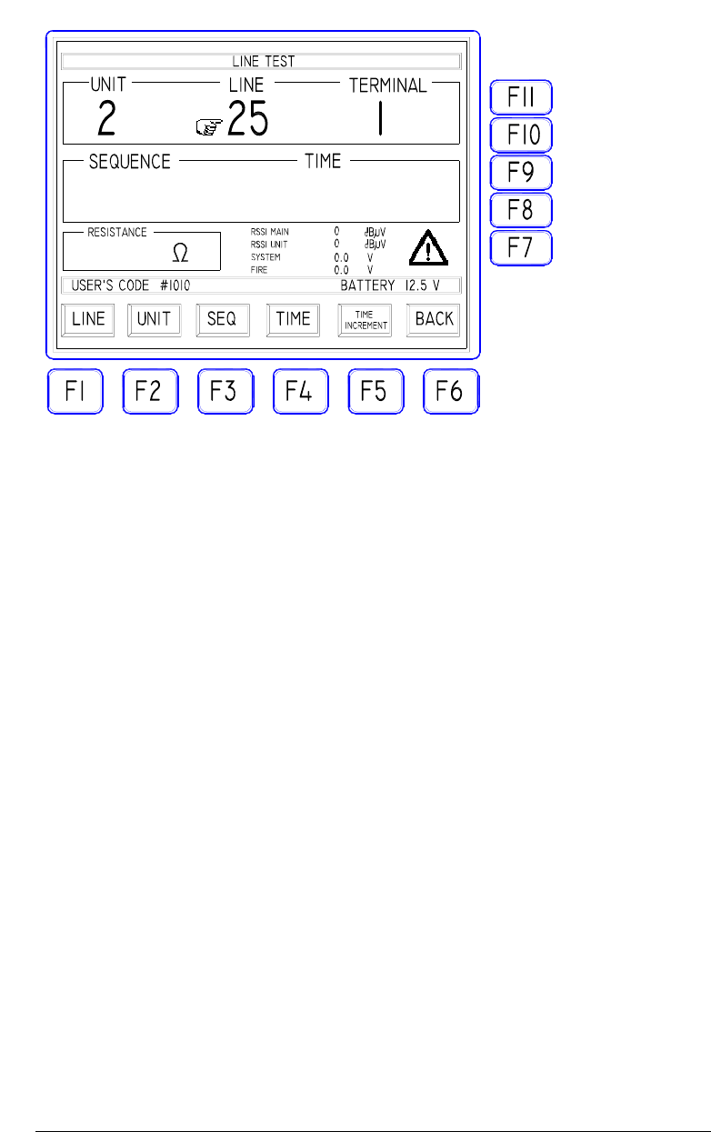
This is the mask as shown when the LINE TEST has been selected: the fields
"SEQUENCE", "TIME", "RESISTANCE" and the values relative to "RSSI
UNIT", RSSI MAIN", "SYSTEM" and "FIRE", are EMPTY or set to ZERO
because none unit has been selected yet.
Using F1 and F2 keys, the parameter to be controlled, "UNIT" or "LINE", can be
selected (the icon with the "finger" appears).
If the choice is for a query of a specific Remote Unit, type on the keyboard the
number of that Unit (i.e. 2) and press ENTER
If the a specific line must be checked, type the line number (e.g.:25) and press
ENTER. In both cases the TX5000 unit will calculate automatically the value of the
remaining parameter and of the terminal; a
data request
will be sent to the Remote
Unit selected..
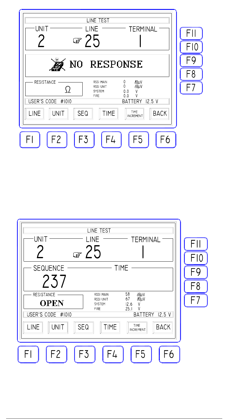
At this point two cases are possible:
1) the Remote Unit selected doesn't "answer" for one of the following reasons:
- The Unit is switched OFF or doesn't exist
- The Unit is ON but the User's Code doesn't match the TX5000 one.
- The Unit is ON, the User's Code is correct but a failure arrived.
- The radio signal strength is too low or the signal is strongly interfered.
For all the above cases, the error message "NO RESPONSE" will be issued:
FIREMASTER IV "
MillenniumThree
" radio shooting system User’s manual
23
2) The Remote Unit selected "answers back" and the data will be printed on the
LCD screen. In the example below: the selected line is NOT connected or the
line resistance is greater than 99 ohm and the sequence of that line is of "no
timed" type. The data will be displayed as follows:
The indication "OPEN" in the cell "RESISTANCE" just warns as the line
resistance is greater than 99 ohm (too high to grant a safe firing with a 24V line
voltage) or the line is OPEN.
The "TIME" value is not shown because the sequence 237 for line 25 of the
Remote Unit N°2, is not a
timed
one.

FIREMASTER IV "
MillenniumThree
" radio shooting system User’s manual
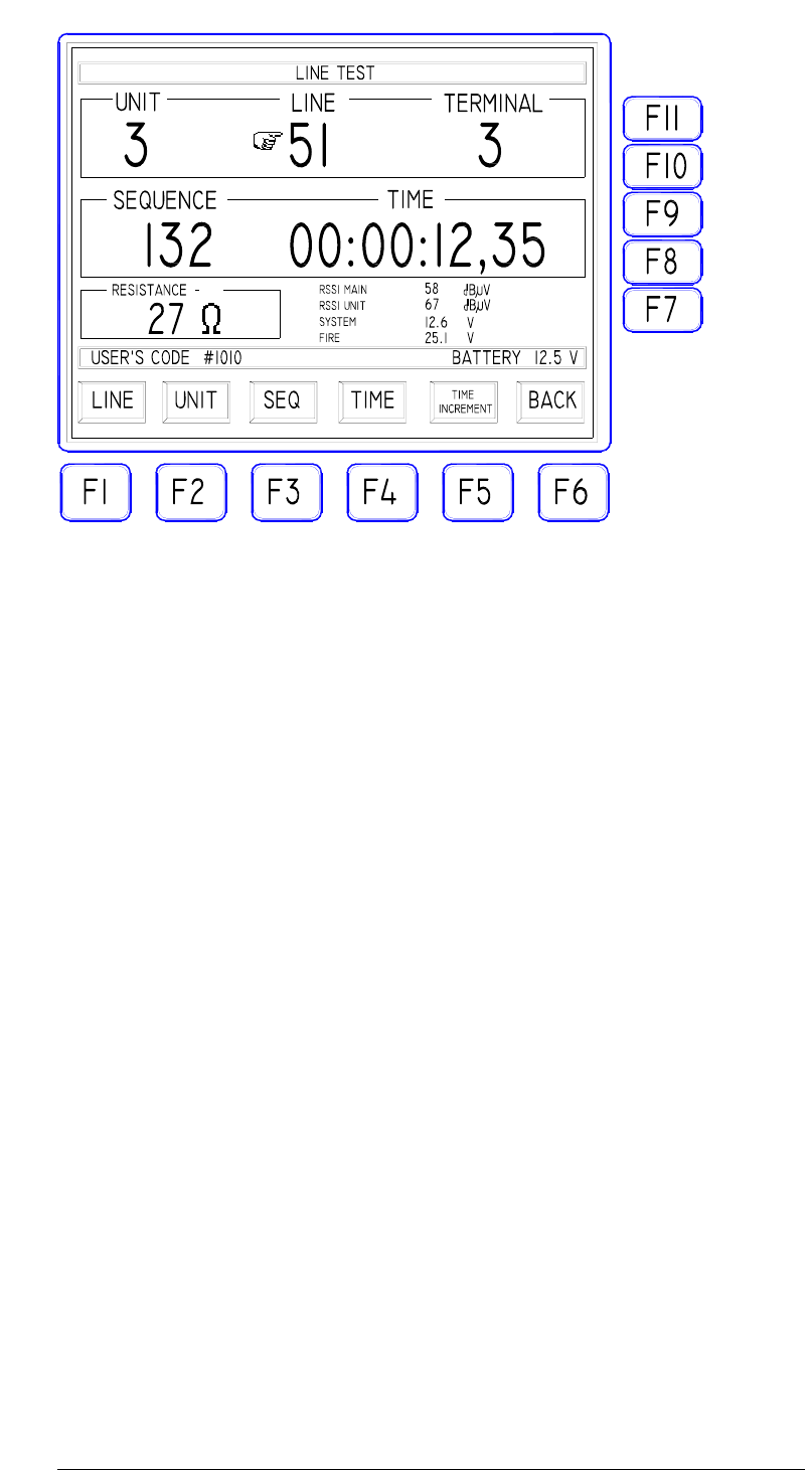
RSSI Main shows a 58dBµV value. This parameter represents the field
intensity (at the antenna of the TX5000 Unit) of the radio signal received
from the Remote Unit. The measuring range spans from 0 to 80dBµV. When
the signal goes down to 20dBµV, the "WARNING" icon appears: the signal
is too low and some communication error could be encountered.
RSSI Unit shows a value of 67dBµV. This parameter represents the field
intensity (at the antenna of the Remote Unit RX48) of the radio signal
received from the Base Unit during the DATA REQUEST of the TX5000.
The measuring range and the details about the signal level are the same as for
the previous example.
SYSTEM shows a value of 12. 6V. This is the voltage of the battery
powering the whole SYSTEM (radio, microcontroller, peripherals, etc.) of the
Remote Unit checked. Should this voltage drop below 11.6V, the
"WARNING" icon will be displayed because the correct voltage level to the
system circuits could be no longer granted.
FIRE shows a value of 25.1V. This is the voltage of the batteries powering
the firing lines of the Remote Unit checked. Also in this case, should the
value drop below 23V, The "WARNING" icon will be displayed because the
necessary power level could be no longer available for the firing lines.
NOTE: when the "WARNING" icon appears, the system can
be still used as usually. One should anyway consider as the system is
working near to the lower limit of its possibilities and thus some
problems more or less severe could be encountered such as: firing failures, no
response from the Remote Unit, errors reading data, etc. Using the system
when the "WARNING" signal is ON, is fully under the responsibility of the
operator: he must evaluate if the show importance is worth the risk of
operating near to the safety limits.
IN ALL CASES THE SYSTEM ALWAYS GRANTS A SAFE
OPERATION AGAINST UNDUE OR PREMATURE FIRINGS.
3) The selected Remote Unit ANSWERS and data are displayed on the screen.
The selected line is connected to a series of 10 squibs with a total resistance
(squibs + cables) of 27 ohm, the SEQUENCE for that line is a
timed
one with
a delay of 12 seconds and 35 hundredths of second. Data will appear as
follows:
24
FIREMASTER IV "
MillenniumThree
" radio shooting system User’s manual
25
When a Remote Unit transmits back data and the situation is similar to the one
depicted at point (2) or (3), the operator can simply read the data values (if the
query was made just to make a CONTROL), or he can take the suitable actions if
some parameter should fall outside the acceptable limits, such as: recharge or
replace the Battery Pack if the read voltages are too low, replace the antenna or vary
the position of the Remote Unit attempting to increase a weak radio signal, or
verify the firing line if the resistance value is too far from the expected value with
reference to the number of connected squibs and the cable length.
If otherwise THE PARAMETERS OF THAT LINE MUST BE
MODIFIED (new programming), then the operation will be as described in
the next chapter.

FIREMASTER IV "
MillenniumThree
" radio shooting system User’s manual
2.1.1
Modify the line parameters
Inside the "TEST LINE" mask, when the Remote Unit sent back the data (a
situation similar to the one described at points (2) or (3) of the previous chapter),
the operator can MODIFY THE PROGRAMMING PARAMETERS. In
detail:
MODIFY A SEQUENCE: press the SEQ key to select the displayed sequence
value, type on the numeric keypad A NEW VALUE FOR THE SEQUENCE you
want to give to this specific line and press ENTER. The Remote Unit containing
that line, will be called and the new value will be written in its memory. The new
sequence value displayed on the screen, CONFIRMS as the whole operation has
been correctly executed (the new value is first written, read back and displayed. In
case of failure the error message "NO RESPONSE" will be issued instead).
HOW TO CHANGE A NORMAL SEQUENCE TO A
TIMED
ONE
If it is needed to define a sequence as a "
timed"
one, proceed as follows:
Select first a line corresponding to the BEGINNING of the timed sequence to be
built and press ENTER. When the data will appear on the screen, press the SEQ
(F3) key and type the SEQUENCE number. If the sequence is not yet timed, press
"TIME" (F4) to time it (initially the time value will be 00:00:00,00). Type in the delay
time value this line must have inside the sequence (if it is the FIRST SHOT of the
sequence, then the time value will be left to ZERO). In order to
time
other lines
and to give the respective delay values inside the sequence, proceed as follows.
HOW TO CREATE A
TIMED
SEQUENCE WITH SEVERAL LINES:
remain with the index pointing SEQUENCE and use F11 and F7 keys to
INCREASE or DECREASE by one the LINE NUMBER. Modify now both the
SEQUENCE NUMBER (all lines of the same timed sequence must have the
SAME SEQUENCE NUMBER), and the TIME value. Should the time intervals
between the sequence shots not equally spaced, TIME must be selected and the
proper time value must be typed for each line inside the sequence.
Note as it is NOT NECESSARY to type ALL the zeroes of the time value, but just
the significant figures. E.g.: if the screen displays a time value of 00:00:00,00 and a
new value of 1,5 seconds must be entered, IT WILL BE NOT NECESSARY to
type 00:00:01,50, BUT JUST 1.5 or 1.50 or again 150.
If otherwise the time intervals between the shots of the same sequence are
EVENLY SPACED, then the job can be greatly simplified using the "TIME
INCREMENT" (F5) function. Lets just suppose to create the timed sequence N°1
including 10 lines starting at 1 and equally spaced by 1 second. Then proceed as
follows:
- "call" the first line of the sequence (1 in this example)
- give this line the needed SEQUENCE VALUE (1).
- If not otherwise timed, use F4 key to assign the time value (00:00:00,00)
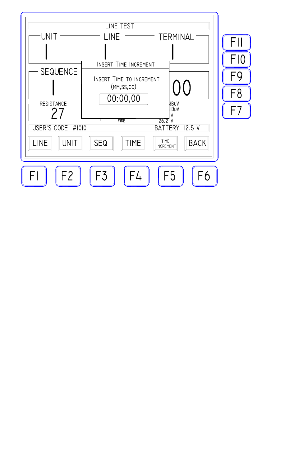
- press F5 "TIME INCREMENT": on the middle of the LCD screen
the mask below will appear. Type now the VALUE FOR THE
CONSTANT TIME INCREMENT spacing the shots of the sequence
(1.00 or 100 meaning ONE second) and press ENTER to confirm.
26
FIREMASTER IV "
MillenniumThree
" radio shooting system User’s manual
Proceed now INCREASING the LINE value with F11 and press the "AUTO
INCREMENT" key on the main keyboard: the time value will be automatically
incremented by the selected quantity and the sequence, if not otherwise set, will be
automatically timed. Continue the same way till the sequence end.
REMOVE THE TIMING FROM A SEQUENCE ALREADY TIMED.
Select the line with the sequence to modify, press now F4 to select "TIME": the
timing option will be CANCELLED simply using the Ð key. If the timing should
be RESTORED, press the Ï key.
WARNING: in order to cancel the timing of a line, IT IS NOT SUFFICIENT to
set at ZERO the time value! You must use the above procedure instead.
HOW TO REMOVE ALL TIMED SEQUENCES FROM THE SAME
REMOTE UNIT.
When a new show is to be created and all Remote Units are to be completely re-
programmed, it could be advisable to define first as NOT TIMED all the lines of
the Units to be used in that show and then proceed to a new programming as
required. It could result UNSAFE (when this should not generate more serious
problems during the show execution), to leave defined as
timed
one or more lines
EVEN IF NOT USED.
The FIREMASTER SYSTEM (just as its previous version) has a practical function
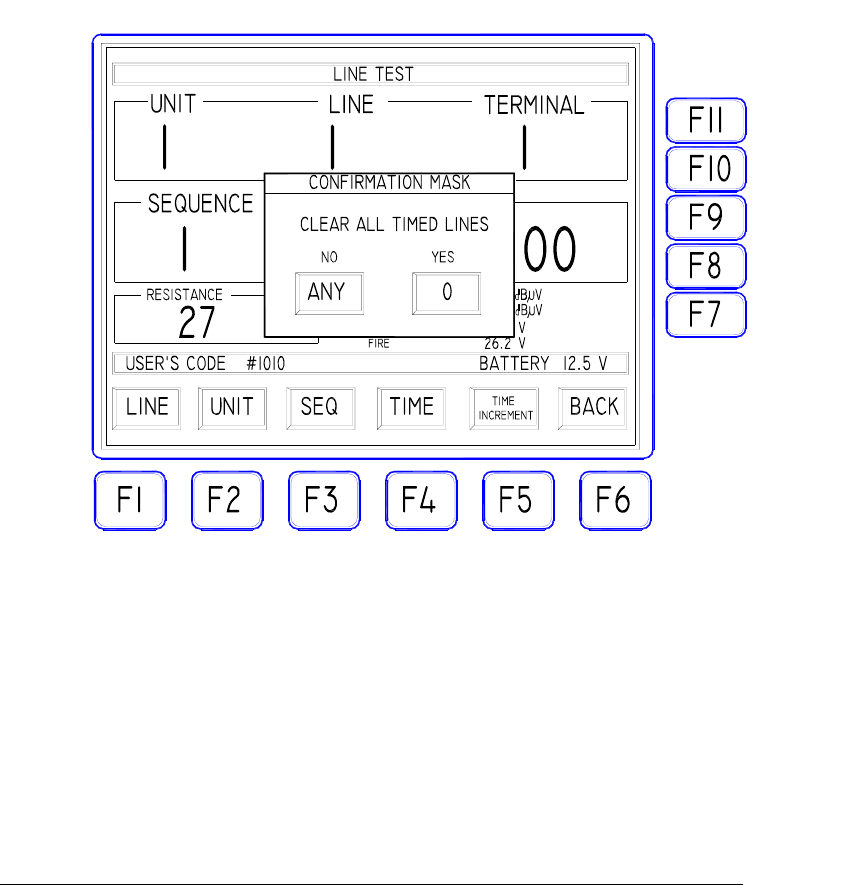
used to do that. It can be activated with F9 key and the following mask will appear:
27
FIREMASTER IV "
MillenniumThree
" radio shooting system User’s manual
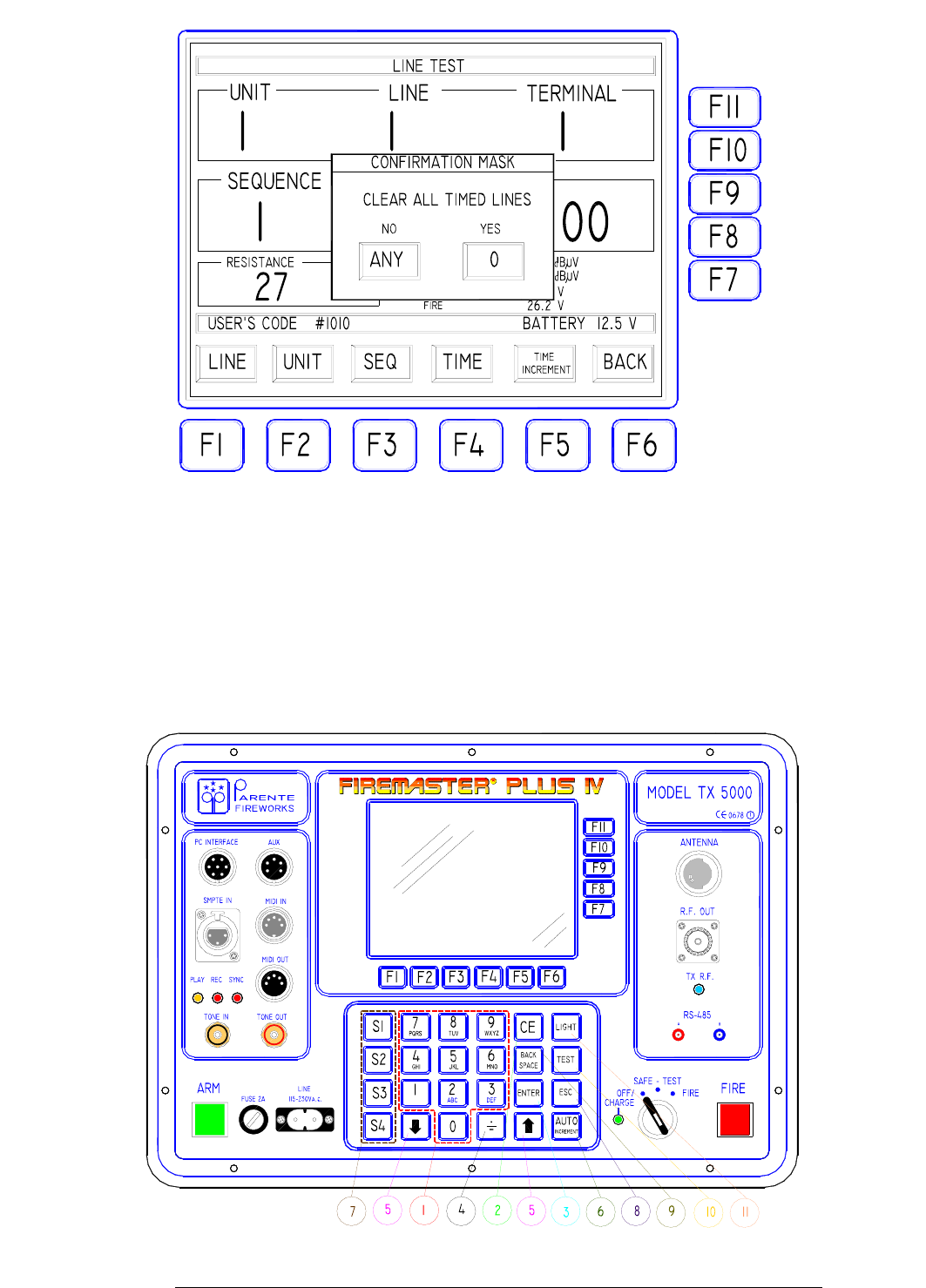
When the "0" key on the numeric keypad will be pressed, a RESET command will
be issued to the selected Remote Unit and all 24 lines will return to the "normal"
mode (no timing). On the completion of this operation the message "OK,
DONE!" will be issued as confirm. Pressing ANY OTHER KEY instead (ANY),
the operation will be cancelled and the function terminated.
28
2.2 GENERAL NOTES USING THE NUMERIC KEYPAD

FIREMASTER IV "
MillenniumThree
" radio shooting system User’s manual
1) Keys 0 to 9 are used to enter numeric values for the parameters requiring so.
Letters are used to insert literal strings for some functions requiring so
(password, show description, etc.)
2) The "CE" key (Clear Entry) is used to cancel a numeric value just after it has
been typed and before it is confirmed.
3) The "ENTER" key is used to confirm the numeric value just typed in or to
send a command to the Remote Units.
4) The "." key is used to insert the comma for the numeric values requiring so or
as a field separator. It is also used to enter the separator (:) for the time values.
5) The keys "ARROW UP" and "ARROW DOWN" allow to INCREMENT or
DECREMENT by ONE the numeric values of the parameter selected by the
index.
6) The "AUTO INCREMENT" key allows to set a constant value for the time
increment used when a sequence must be
timed
(see previous chapter).
7) S1 to S4 keys ARE NOT IMPLEMENTED in the present version of TX5000
and are RESERVED to future expansion.
8) ESC key IS NOT IMPLEMENTED in the present version of TX5000 and is
RESERVED to future expansion.
9) BACKSPACE key can be used during typing of numeric values to step back by
one position when a correction of the typed value is needed.
10) TEST key IS NOT IMPLEMENTED in the present version of TX5000 and
is RESERVED to future expansion.
11) LIGHT is a “toggle” key controlling the AUXILIARY PANEL LIGHT (a
flexible LED service lamp to be connected at AUX connector on the front
panel). The lamp is NORMALLY OFF and can be turned immediately ON
using the LIGHT key. Pressing again the LIGHT key while the lamp is ON,
will turn it immediately OFF. The lamp remains ON during 10 MINUTES
then, if no other action is performed on the keyboard, it automatically is
SWITCHED OFF to save energy.
29

FIREMASTER IV "
MillenniumThree
" radio shooting system User’s manual
2.3
"TEST UNIT" ICON
The high-resolution graphic display of the new FIREMASTER IV SYSTEM,
allows to display at the same time a lot more information than it was possible on
the previous version.
The "TEST UNIT" function in particular, uses this possibility to display, WITH
A SINGLE COMMAND, the complete situation relative to all 24 lines of a
selected Remote Unit.
IMPORTANT NOTICE: as previously remarked, the new FIREMASTER
IV "
Millennium Three
", is completely compatible with the previous
versions FIREMASTER II and FIREMASTER III. Nevertheless, the
behavior of the "old" Remote Units RX24-A, when inquired using the
"TEST UNIT" function, cannot be identical to the one of the new
generation Units. The compatibility has been anyway maintained to the
detriment of the response time. While the new RX24-B and RX48 Units
implement a special function to send back a whole "block" of data relative
to the 24 lines with a single operation, the previous RX24-A Units will do
that A LINE AT THE TIME and it will be then necessary 24 consecutive
transmission. This process is carried out in a complete automatic way and it
results completely "transparent" to the user, provided he previously
specified correctly the numbers relative to the RX24-A Units in the "OLD
UNITS SETUP". However, when a TEST UNIT request is sent to a RX24-
B Unit or RX48 (new type), the parameters relative to ALL 24 LINES will be
displayed in only about 4 seconds. If the same command is otherwise sent
to a RX24-A Unit ("old" type), exactly the same result will be obtained, but
it will be necessary to wait about 25 seconds (the 24 lines are tested
automatically one at the time). If otherwise the TEST UNIT function is
used with an "old" typ RX24-A Unit, without previously specify its number
inside the "OLD UNITS SETUP" mask, then the Unit WILL NOT
RECOGNIZE THIS COMMAND (the "LINE TEST" menu must be
used instead).
30
FIREMASTER IV "
MillenniumThree
" radio shooting system User’s manual
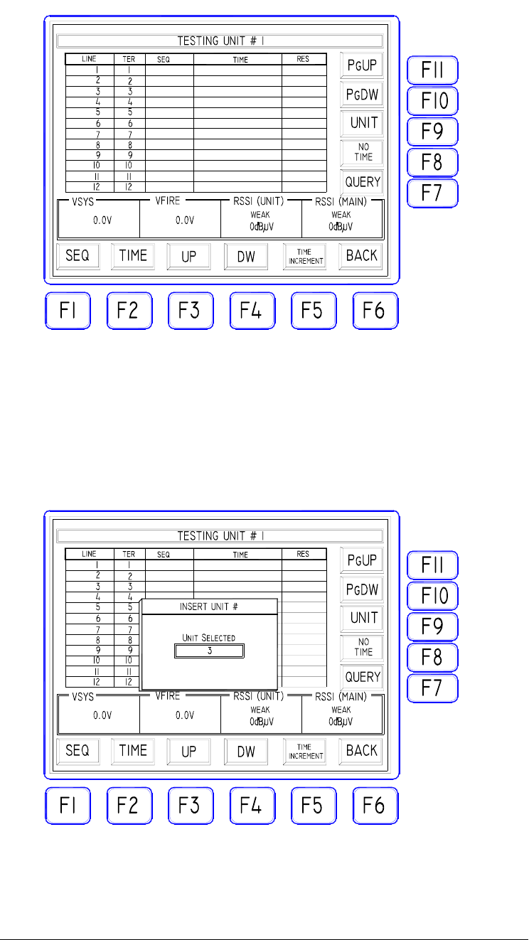
From inside the mask "TEST MENU" select the "TEST UNIT" icon: the mask
"TESTING UNIT #…" will appear
Because a specific Remote Unit has been not selected nor checked yet, by default, it
will be shown the 12 first lines situation of Remote Unit #1. All parameters are still
unassigned or set to ZERO.
Press the key F9 "UNIT" to select, among the ACTIVE Remote Units, the one to
be checked. It will be shown a window to type in the Unit number (1 to 255).
Press "ENTER" to confirm the data: the Base Unit TX2000 will start immediately
to send a data request for the selected Remote Unit. A time interval of about 4
seconds is necessary to check the Unit and obtain the answer with all data. During
this time, the following message will be displayed.
31
FIREMASTER IV "
MillenniumThree
" radio shooting system User’s manual
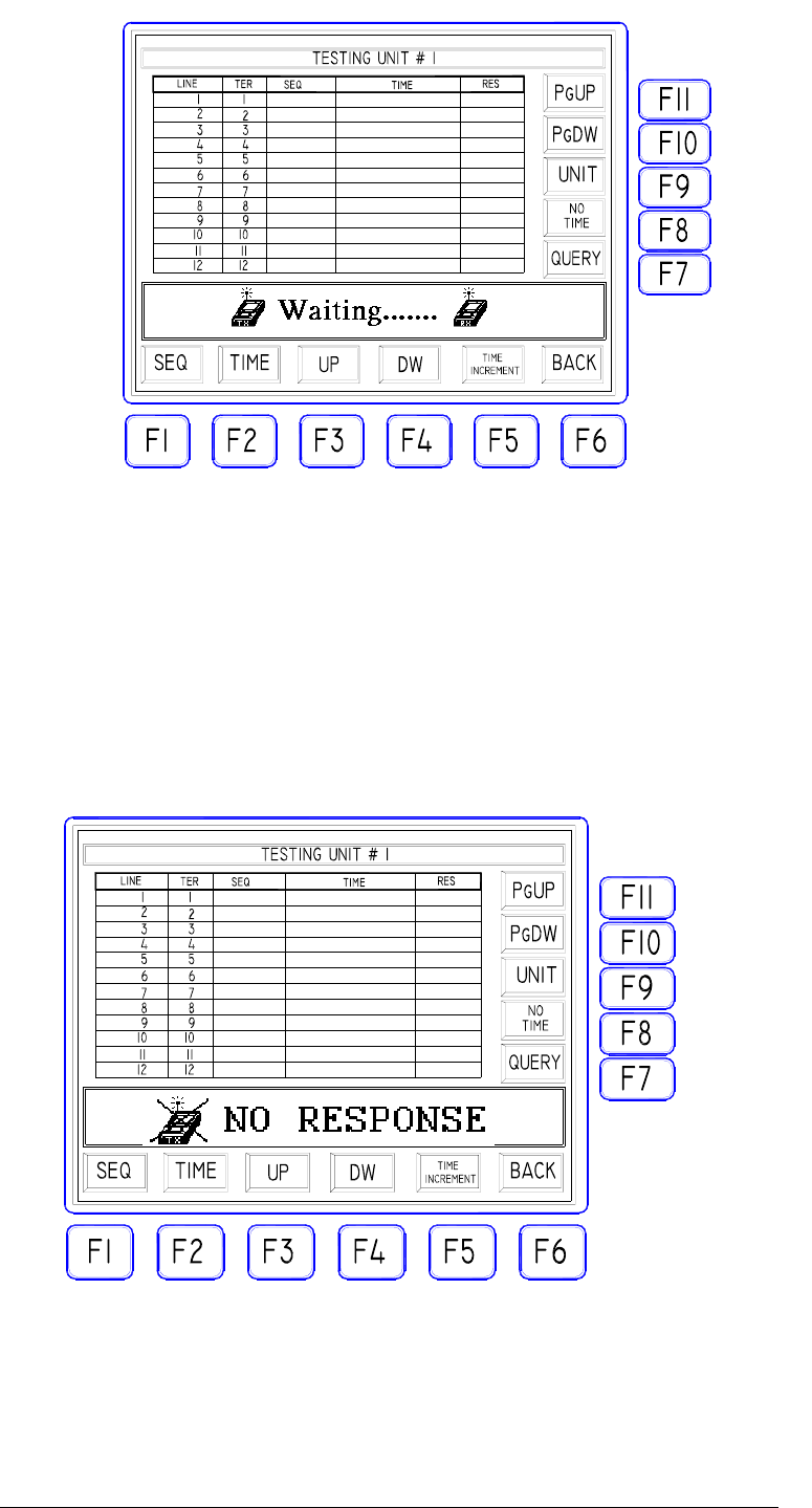
If the Remote Unit shouldn't reply immediately, two more attempts of
connection will be automatically made: after that an error message will be
issued.
We already listed the possible causes of answering failure (
the Unit is switched
OFF or doesn't exist, the Unit is ON but the USER'S CODE doesn't match
the TX5000 one, the Unit is ON and the code is correct but a FAILURE
occurred, the radio signal intensity is too low or the signal is strongly
interfered
).
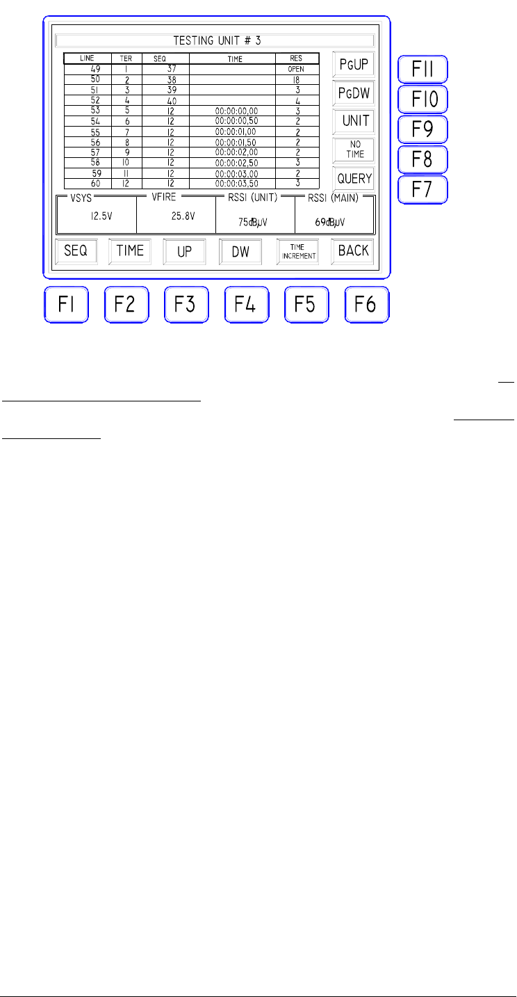
If otherwise the Remote Unit answers correctly, all data sent back will be
displayed inside the table cells:
32
FIREMASTER IV "
MillenniumThree
" radio shooting system User’s manual
In the example above, the Remote Unit #3 has been checked and it sent back all
data contained in its memory : sequence (SEQ) and relative time (TIME) for all
lines eventually defined as "
timed sequence".
The following real-time
measurements have also been received and displayed: SYSTEM battery voltage
(VSYS), LINE battery voltage (VFIRE), RECEIVED radio signal strength
(RSSIunit), intensity of the radio signal SENT BACK (RSSImain) and ohmic
resistance of each firing line (RES).
Note as, while the real-time measurements, represent the actual values read
during the Unit check (they can vary at each new query), all data relative to the
firing lines are permanently stored inside the Unit memory and will remain
unchanged until the operator will overwrite it using the specific commands.
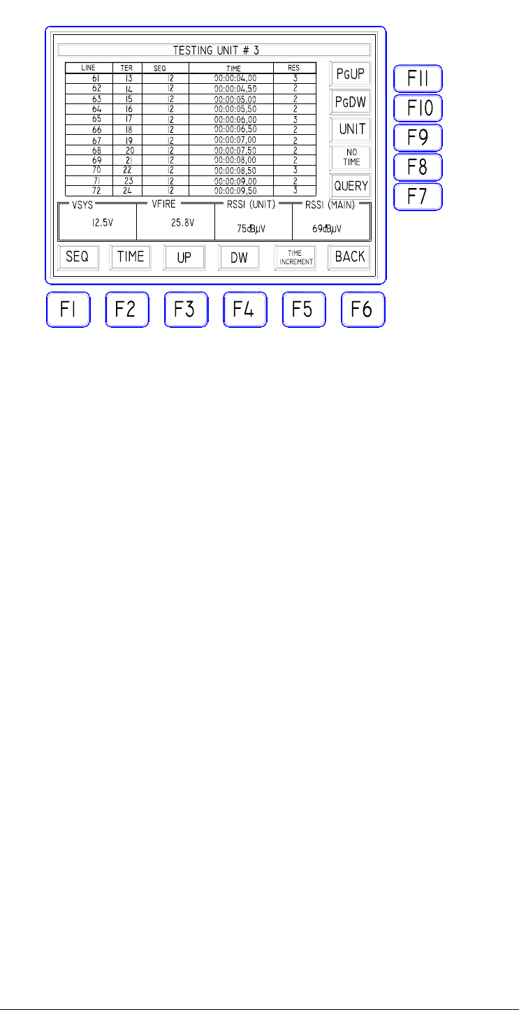
Due to the limited space on the graphic LCD screen, it is impossible to display at
the same time the situation of all 24 lines for the Remote Unit under test. The
data relative to the first 12 (1 to 12) lines will be shown and the operator can
visualize the remaining 12 (13 to 24), using the F10 key "PGdw". Using F11
"Pgup" the first 12 lines can be visualized again. Note as these operations produce
just a change in displaying data and NOT A NEW DATA REQUEST to the
Remote Unit that already sent all data since the first call.
33
FIREMASTER IV "
MillenniumThree
" radio shooting system User’s manual
To REPEAT the call to the same Remote Unit, it will be sufficient to press F7
"QUERY". The operation can be repeated as many times as needed and can be
used to control in real time an eventual variation of the working parameters of the
Remote Unit (line resistance, battery voltage, radio signals intensity).
To call a different Remote Unit, it will be necessary to use F9 "UNIT" as
previously described.
2.3.1
DATA MODIFICATION
Data, as received from a Remote Unit and displayed on the screen of the Base
Unit TX5000, can be edited following the show requirements.
With reference to the pictures of the previous example (data received from the
Remote Unit #3), let us see, step by step, how to proceed.
It must be pointed out first as some of the displayed data are relative to real-time
measurements or factory settings and thus they cannot be edited. In detail:
- LINE: this is the line number of a specific Remote Unit for each of its 24
lines. The line numbers are PERMANENTLY ASSIGNED for each Unit
and thus, when a Remote Unit is called, they are automatically defined.
- TER: this is the physical position of the binding posts of a specific line on the
panel of the Remote Unit. In our example, TER 3 means the third couple of
terminals of Unit #3: this couple has been permanently given the line number
51.
- RES: this is the value, measured in OHM, of the line resistance connected to
the terminals of the Unit. This measurement is made each time the Unit or a
specific line is called. All lines with a resistance greater than 99 ohm, or NOT
34

FIREMASTER IV "
MillenniumThree
" radio shooting system User’s manual
CONNECTED, are regarded as OPEN CIRCUIT and the corresponding
message "OPEN" will be displayed in the cell RES
- VSYS: this is the value, measured in volt, of the SYSTEM battery
(microcontroller, peripherals, radio) on the Remote Unit. The measurement is
made EACH TIME the Unit or a specific line is called. If the voltage of this
battery falls down a preset value, the error message "FAULT" will be
displayed. This message shouldn't regarded as a catastrophic failure on the
Remote Unit, but it is just a WARNING about the poor charge level of the
battery (a recharge is urgently needed!)
- VFIRE: this is the value, measured in volt, of the FIRING LINES
BATTERIES on the Remote Unit (2 batteries in series for 24V total). The
measurement is made EACH TIME the Unit or a specific line is called. If the
voltage of these batteries falls down a preset value, the error message
"FAULT" will be displayed. This message shouldn't regarded as a catastrophic
failure on the Remote Unit, but it is just a WARNING about the poor charge
level of the batteries (a recharge is urgently needed!).
- RSSI(unit): it represents the value, in dBµV, of the field strength present at
the receiving antenna on the Remote Unit. Practically: this reading gives an
idea of the quality of the radio reception on the Remote Unit during a request of
data. The measuring range is between 0 and 80dBµV (0dBµV = NO
SIGNAL, 80dBµV = MAXIMUM SIGNAL). When the reading is BELOW
20dBµV, some error in data reception could occur and it would be advisable
to check the antenna or Unit position (see specific notes to the relative
chapter) in order to improve the radio signal level. When the reading is down
to 12dBµV, the warning message "WEAK" is displayed.
- RSSI(main): it represents the value, in dBµV, of the field strength present
at the receiving antenna on the Base Unit. Practically: this reading gives an idea
of the quality of the radio reception on the Base Unit during the reception of
answer back from the Remote Unit. All other details are the same as in the
previous case.
The only data the operator can modify are: SEQ ("SEQUENCE") and TIME.
In order to modify these parameters, the keys F1 (SEQ), F2 (TIME), F3 (UP), F4
(DW - down) will be used. Eventually also F11 (Pgup) and F10 (PGdw) if the data
to be modified are not displayed in the actual page. In any case F3 and F4 keys,
provide to scroll automatically the displayed lines when the table limits are reached.
Using the above listed keys, it will be marked (in reverse) the parameter relative to
the specific line to be changed and the new value will be typed in directly using the
numeric keypad; ENTER will confirm the value and the new data will be
immediately sent to the Remote Unit and stored accordingly in memory.
All data relative to TIME can be also typed without the separators and disregarding
all non-significant zeroes. E.g.: the time value 00:17:12,35 (17 minutes, 12 seconds
and 35 hundredths) can be typed "171235" as well as "17.12.35" or "00.17.12.35" or
again as "00171235". It will be accepted in all cases.
35
FIREMASTER IV "
MillenniumThree
" radio shooting system User’s manual
2.3.2
HOW TO REMOVE ALL TIMED SEQUENCES FROM
THE SAME REMOTE UNIT
Press the F9 key "UNIT" followed immediately by the F8 key "NO TIME": the
following mask will appear
When the "0" key on the numeric keypad will be pressed, a RESET command will
be issued to the selected Remote Unit and all 24 lines will return to the "normal"
mode (no timing). On the completion of this operation the message "OK,
DONE!" will be issued as confirm. Pressing ANY OTHER KEY instead (ANY),
the operation will be cancelled and the function terminated.
36