Parente Fireworks Srl FIREMASTER4KT Firemaster IV Base Station User Manual SISTEMA FIREMASTER III
Parente Fireworks Srl Firemaster IV Base Station SISTEMA FIREMASTER III
UserManual.wiki
>
Parente Fireworks Srl
>
FIREMASTER4KT User Manual
>
Users Manual II
Contents
1.
Users Manual I
2.
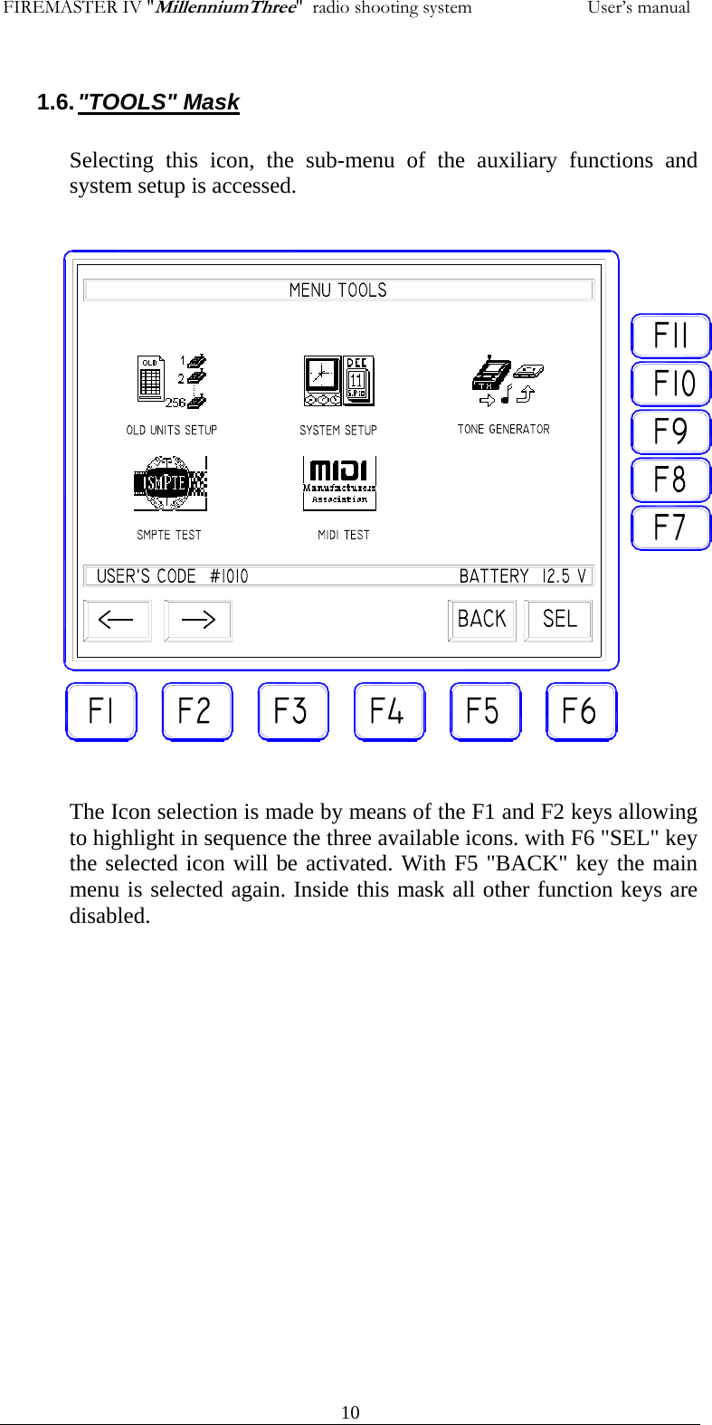
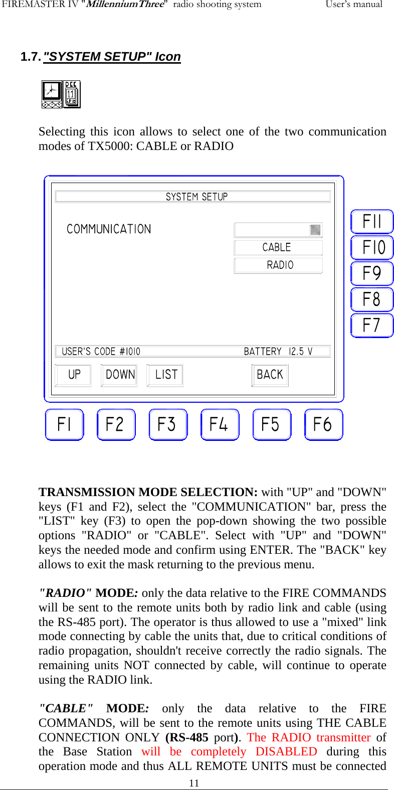
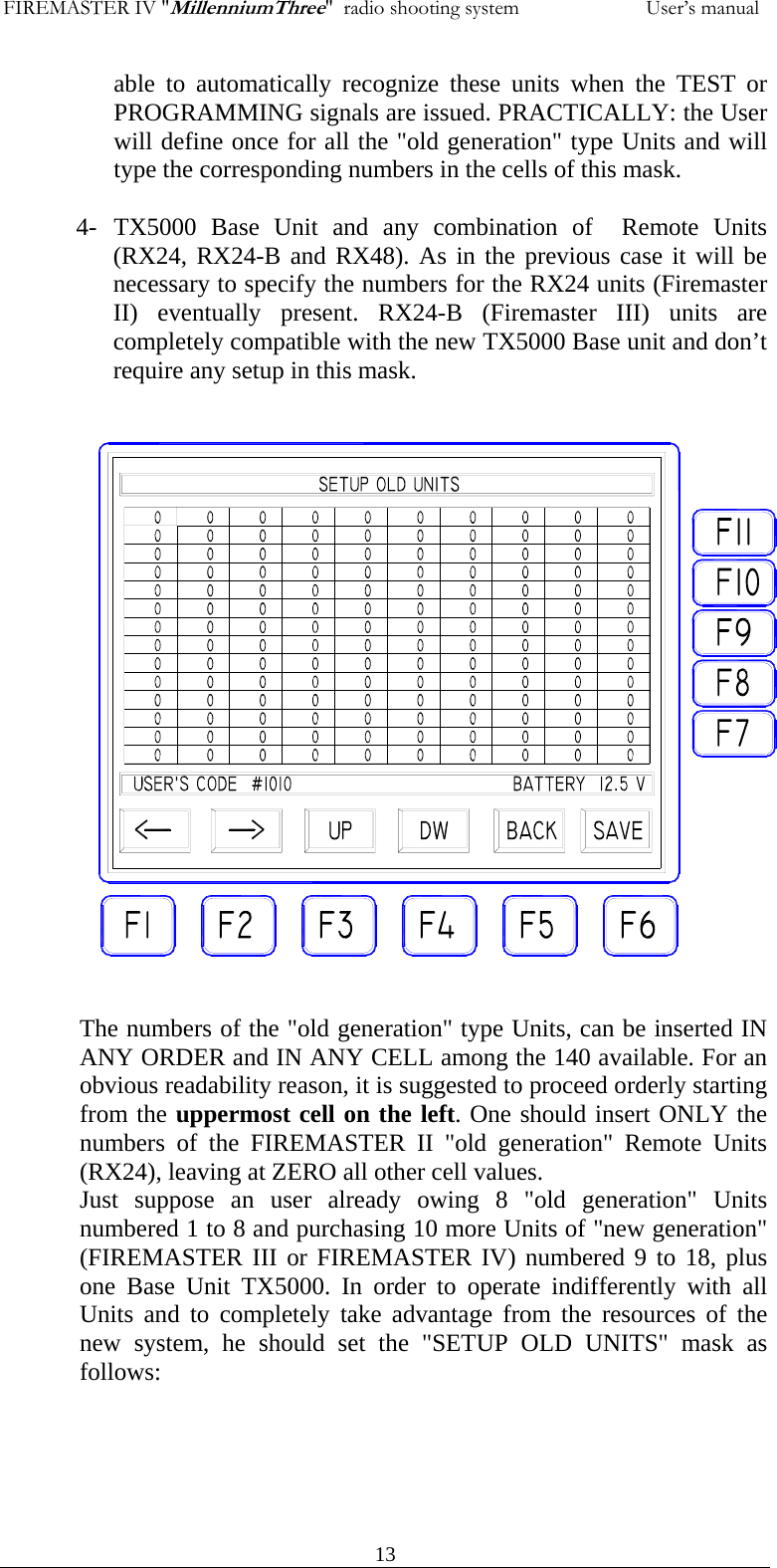
Users Manual II
3.
Users Manual III
4.
Users Manual IV
5.
Users Manual V
6.
Users Manual VI
7.
Users Manual VII
8.
Users Manual VIII
9.
Users Manual IX
10.
Users Manual X
11.
Users Manual XI
Users Manual II
Navigation menu
Upload a User Manual
Namespaces
Wiki Guide
HTML
PDF
Info
Views
User Manual
Discussion / Help
Navigation