Park Air Systems B3060V2 Defence Radio for Civil and Military applications User Manual G DO JDBIN GA8784 Issue 1 eps
Park Air Systems Limited Defence Radio for Civil and Military applications G DO JDBIN GA8784 Issue 1 eps
User guide

ISSUE 2
Series 3000DV2 Radios
User Guide
/ FCC

Handbook Title: Series 3000DV2 Radios User Guide
Handbook Part Number: 31-33000DTR
Issue Number: 2
Date of Issue July 2000
Page ii 3000DV2 Radios
/ FCC
Handbook Amendment Record
Amendments to this handbook, originated by Park Air Electronics, are listed in the following table.
Amendment
Number
Date Brief Details PAE Change
Note Number
Equipment Modification Record
Modifications to the 3000DV2 radios are detailed in the following table.
Modification
Number
Date Brief Details PAE Change
Note Number
1March '99 RF PA capacitors C17, C26, C39, C40 changed. 3590
3000DV2 Radios Page iii
Warnings
Warning. Lethal Voltages!
Installation involves the connection of lethal voltages. The instructions detailed in this
handbook must be carried out only by suitably qualified personnel.
Warning. Heavy Item!
The 3000DV2 series radios weigh in excess of 25 kg; care must be taken when lifting
and handling these units. At least two people must be used to lift the equipment.
Warning. Antenna Radiation!
Antennas used with 3000DV2 transmitters and transceivers must be installed such
that the resultant radiated field strength is below 10 watt per square metre in areas
normally accessible to personnel.
Warning. Beryllium/Beryllia!
The equipment covered by this handbook contains components incorporating the
highly toxic material Beryllium and/or its oxide Beryllia. No instructions within this user
guide require the removal of the radio's top or bottom covers so users are not exposed
to a potential beryllium hazard. If the radio is to be disposed of, users must be aware of
current disposal regulations regarding equipment containing Beryllium/Beryllia.
Caution
Caution. Electrostatic Sensitive Devices!
The equipment covered by this handbook contains electrostatic sensitive devices
some of which are exposed when the rear panel is hinged down to obtain access to the
mains voltage selector (see section 3 page 8 ). Observe handling precautions to avoid
static charges which may damage these devices.
FEDERAL COMMUNICATIONS COMMISSION (FCC) REGULATIONS
q This device complies with Part 15 of the FCC Rules. Operation is subject to the
condition that this device does not cause harmful interference.
q You are required to obtain a station licence before transmitting from your base station.
q This equipment is only licenced for operation on 25 kHz channel spacing in the
VHF aeronautical band of 118 MHz to 136.975MHz employing amplitude modulation.
q The base station power output must not exceed the output necessary for satisfactory
technical operation taking account of local conditions and the area to be covered.
q The base station's frequency and parameters should be checked by authorized service
personnel before use, and at least yearly thereafter.
------------------------------------------------------------------------------------------------------------------------
Page iv 3000DV2 Radios

Contents
This handbook is divided into the following sections
Section 1 General Information
Section 2 Specification
Section 3 Installation and Setting-Up Instructions
Section 4 Operation
Section 5 Spares
Section 6 Figures
3000DV2 Radios Page v

General Information
Contents
Paragraph
1 Introduction
4 Equipment overview
8 Power supplies
10 Built-in test facility
12 Types of installation
13 Control of equipment
16 Options
17 VHF/UHF guard receiver (option 01)
18 Configurable antenna port (option 04)
19 Fill gun port (option 05)
20 External power amplifier/filter drive (option 06)
21 Internal have quick (option 07)
22 VHF frequency extension (option 08)
23 Maritime band (option 10)
24 Internal quick fox module (option 12)
25 User maintenance
Table Page
1-1 Options - Model Applicability 5
INTRODUCTION
1 This handbook describes the installation and operation of the Park Air Electronics (PAE) series
3000DV2 radios. The series comprises the following models:
❏3040V2 UHF transmitter/receiver
❏3070V2 VHF transmitter/receiver
❏3060V2 VHF/UHF transmitter/receiver
❏3140V2 UHF transmitter
❏3170V2 VHF transmitter
❏3160V2 VHF/UHF transmitter
❏3240V2 UHF receiver
❏3270V2 VHF receiver
❏3260V2 VHF/UHF receiver
3000DV2 Radios Section 1
Page 1

2 The purpose of this handbook is to provide sufficient information to successfully install and operate
the radios. No topics covered in this book involve power being applied with any equipment covers
removed. A full technical description, to component level, of each radio is provided in an associated
technical handbook. Details of how to order copies of the technical handbooks are given in section 5.
3 This handbook is divided into six sections. The sections cover the following topics:
❏Section 1. Provides an overview of the equipment, and details the various installation options.
❏Section 2. Provides the technical specification of the equipment.
❏Section 3. Provides installation and commissioning instructions for the equipment. It must be
noted that the installation involves the connection of lethal voltages to the equipment.
Installation must therefore be carried out only by suitably qualified personnel.
❏Section 4. Describes the purpose of the equipment’s controls, connectors and indicators.
Also provided is an example setting-up procedure, operating instructions, and user
maintenance procedures.
❏Section 5. Lists the spare parts applicable to the topics covered in this handbook (each
equipment’s full parts-listing is contained in the associated technical handbook).
❏Section 6. PAE drawings applicable to this handbook. The drawings are referenced in the text
as Fig. 1, Fig. 2 etc. It should be noted that in-text illustrations are referenced by the section and
figure number; for example, Fig. 3-1.
EQUIPMENT OVERVIEW
4 Series 3000DV2 radios can operate in the VHF 100 to 163 MHz and/or UHF 225 to 339.975 MHz
frequency bands, with 25 kHz channel spacing. 8.33 kHz channel spacing is also available in the VHF
band between 118.000 MHz and 136.975 MHz. Standard operating modes are amplitude modulation
(AM) or frequency modulation (FM) with both clear voice and data (16 kBit cypher) modes selectable.
When 8.33 kHz channel spacing is used, the radio automatically defaults to AM, clear voice mode.
5 The radios are suitable for use in voice encryption systems and Link 11 applications. All UHF sets
can be equipped with an internal ECCM module to provide Have Quick II frequency hopping operation
(for Have Quick operating instructions refer to document PAE 31B33060SUP).
6 The equipment’s operating frequency is selected using the front panel’s numeric data keys. Up to
99 pre-set channels can be stored in the equipment’s memory. Each stored channel contains frequency
and operating mode information. Pre-set channels can be recalled for operational use, or recalled for
display without altering the operational frequency.
7 The transceiver and transmitter equipments produce a maximum output of 40 watts in AM mode
and 60 watts in FM mode. The output power can be reduced by using a front panel control. If a PAE
3640 power amplifier is used in conjunction with a 3000DV2 transmitter or transceiver, the radio’s FM
output is automatically reduced to 40 watts to produce a 100 watt output from the power amplifier.
Power Supplies
8 The radios can be operated from standard ac input supplies, or from a low voltage dc supply (refer
to section 2, specification). Both ac and dc input supplies can be simultaneously connected to the
equipment.
Section 1 3000DV2 Radios
Page 2

9 When both ac and dc supplies are connected, operation from the ac supply takes priority; automatic
change-over to the dc supply will occur if the ac supply fails. On restoration of the ac supply, the
equipment reverts to ac operation.
Built-in Test Facility
10 A built-in test (BIT) facility monitors essential parameters within the equipment, and displays an
error message if a fault is found. The BIT functions in three different ways:
❏It allows certain equipment parameters to be displayed only when selected by the user.
❏It continuously performs certain test routines while the equipment is operating.
❏It provides a complete check of the equipment when selected to do so by the user. During this
operation, normal operation of the equipment is suspended.
11 Full details of BIT operation and the resultant error messages are given in section 4.
TYPES OF INSTALLATION
12 The series 3000DV2 radios can be installed in one of four ways:
❏Mounted on fixed runners within a standard 483 mm (19 inch) equipment rack.
❏Fitted on telescopic slides within a standard 483 mm (19 inch) equipment rack.
❏As a free-standing desktop equipment using the PAE free-standing accessory kit.
❏In mobile applications using the PAE free-standing accessory kit plus an anti-vibration mount
kit.
Control of Equipment
13 The radios can be controlled in local, or remote modes. In local mode, control of the equipment is by
using the front panel controls and indicators as detailed in section 4. In addition to the front panel
controls, a number of inputs, outputs and control facilities can be configured through the rear panel
facilities socket. A full list of the facilities can be found in section 3.
14 As an alternative to local control, a PAE series 3000V2 Remote Control Unit (RCU) can be used; the
RCU replicates many of the radio’s front panel controls and indicators. The radio’s remote control
module can be configured for operation through dc or ac (tone) circuits. When configured for dc
operation, the RCU can be located (using suitable land lines) up to 1 km (1043 yards) from the
equipment. When configured for ac operation, no dc path is required between the equipment and the
RCU; this enables the control circuits to be routed, for example, through a microwave link.
15 For remote management of the equipment, and when part of a communication system, the PAE
Multi-Access Remote Control (MARC) system can be used.
3000DV2 Radios Section 1
Page 3

OPTIONS
16 In addition to the standard operational functions the following options are available (see Table 1-1
for applicability to your model). Some of the options require additional hardware; others are built-in the
radio and are available when the option is selected from the front panel. Table 1-1 details which options
can be fitted to which radio.
VHF/UHF Guard Receiver (Option 01)
17 Guard receiver module operating on 121.5 or 243.00 MHz AM. Can be configured for independent
or combined (with main receiver) antenna operation. This option requires an additional module to be
fitted in the radio.
Configurable Antenna Port (Option 04)
18 Configurable antenna switching. This includes single and multi-antenna options configured to a
customer’s requirements.
Fill Gun Port (Option 05)
19 Provides a front panel fill gun port (for use with Have Quick radios).
External Power Amplifier/Filter Drive (Option 06)
20 A multi-purpose interface for use with an external power amplifier, or an auto-tune filter. This option
is built-in and becomes operational when selected from the radio’s front panel.
Internal Have Quick (Option 07)
21 Option 07 provides a Have Quick II ECCM capability. This option requires an additional module to
be fitted in the radio.
VHF Frequency Extension (Option 08)
22 Provides for extension of the VHF frequency range to cover 100 to 163 MHz. This option is built-in
and becomes operational when selected from the radio’s front panel.
Maritime Band (Option 10)
23 Provides pre-programmed international maritime channels within the frequency range of 156 MHz
to 163 MHz. Information regarding maritime frequency channels is given in section 4 of this handbook.
This option is built-in and becomes operational when selected from the radio’s front panel.
Section 1 3000DV2 Radios
Page 4

Internal Quick Fox Module (Option 12)
24 Option 12 provides a Quick Fox ECCM capability. This option requires minor modification to the
standard radio and an additional module to be fitted.
Table 1-1 Options - Model Applicability
Model
Options
01 04 05 06 07 08 10 12
Transceivers:
3070V2 VHF
3040V2 UHF
3060V2 V/UHF
4
4
4
4
4
4
7
4
4
4
4
4
7
4
4
4
7
4
4
7
4
7
4
4
Transmitters:
3170V2 VHF
3140V2 UHF
3160V2 V/UHF
7
7
7
4
4
4
7
4
4
4
4
4
7
4
4
4
7
4
4
7
4
7
4
4
Receivers:
3270V2 VHF
3240V2 UHF
3260V2 V/UHF
4
4
4
4
4
4
7
4
4
4
4
4
7
4
4
4
7
4
4
7
4
7
4
4
4= available 7= not available
Options shown shaded are built-in to all applicable radios
and can be made operational from the front panel (see section 4)
USER MAINTENANCE
25 User maintenance is limited to cleaning the rear panel air filter and checking the frequency accuracy
of the equipment. The procedures for user maintenance are provided in section 4.
3000DV2 Radios Section 1
Page 5

Specification
Contents
Paragraph
1 General
2 Input supplies
3 Dimensions and weight
4 Environmental
Transmitter
5 RF characteristics
6 Modulation characteristics (speech A3E, F3E)
7 Modulation characteristics (data AXX, FXX)
Receiver
8 RF characteristics
9 AF characteristics (speech A3E, F3E)
10 AF characteristics (data AXX, FXX)
11 Remote control decoder
12 Guard receiver specification
GENERAL
1 This section provides the specification for the series 3000DV2 radios. The specification covers all
models, therefore, users should only read those parts of the specification applicable to their equipment.
Frequency range:
VHF 100 to 155.975 MHz
100 to 163 MHz when Option 08 is selected
UHF 225 to 399.975 MHz
Frequency error £1.5 ppm (-20°C to +0°C)
£1 ppm (0°C to +55°C)
Ageing £1 ppm/year
Channel spacing 25 kHz
8.33 kHz (only available between 118 and
136.975 MHz, AM voice band. See FCC Warning)
pre-set channels 99
Time for frequency change £8ms
3000DV2 Radios Section 2
Page 1

Classes of emission A3E, AXX, F3E, FXX
Link 11 to STANAG 5511
Have Quick to STANAG 4246 (Option 07)
Antenna configuration Independent VHF and UHF antenna ports are
provided as standard, other configurations are
optional (Option 04)
INPUT SUPPLIES
2 The equipment operates from an ac or dc input supply. The voltage ranges and system readiness
data are:
Power supply 110/120 V or 220/240 V, 45 to 65 Hz ±10% from
selected tap
Consumption: 700 VA (Tx/TR models)
175 VA (Rx models)
DC 22 to 32 V. Negative earth
Consumption: 18 A (Tx/TR models)
3 A (Rx models)
System readiness <10 seconds
DIMENSIONS AND WEIGHT
3 The dimensions and weight of the equipment are:
Width (W) 430 mm (width to the extremities of side heatsink
fins)
Height (H) 178 mm
Depth (D) 597 mm (depth from rear mounting face). Front
panel projections 41 mm (from mounting face)
Weight 32 kg
ENVIRONMENTAL
4 The temperature and relative humidity ranges, and other environmental data are:
Temperature range:
Operating -20°C to +55°C
Storage -40°C to +70°C
Section 2 3000DV2 Radios
Page 2

Duty cycle Continuous operation up to +55°C
Relative humidity:
Operating 95% at 55°C MIL STD 810C
Storage 85% at 40°C MIL STD 810C
Salt fog Complies with MIL STD 810C
Vibration and shock:
Shock 40 g, 6 ms
Vibration 10 to 500 Hz MIL STD 810C
EMC To MIL STD 461/462D part 4
TRANSMITTER
RF Characteristics
5 The characteristics of the transmitter’s RF output are:
Carrier power output 40 W AM; 60 W FM. FM power is automatically
reduced to 40 watts when a serviceable PAE 3640
power amplifier is connected to a UHF transmitter or
transceiver.
±0.5 dB over operating band
±1 dB over temperature range
0 to 10 dB front panel adjustment
Power reduction Output power is automatically reduced under the
following conditions:
❏when VSWR exceeds 2.5:1 (gradual reduction to
-10 dB at infinite VSWR)
❏when dc supply falls below 26 V (1 dB nominal
reduction)
❏when the temperature exceeds 80°C (6 dB
reduction)
❏when the temperature exceeds 90°C (9 dB
reduction)
Permissible mismatch Infinite VSWR
Harmonic outputs Better than -70 dBc (-60 dBc between 225 and
230 MHz)
3000DV2 Radios Section 2
Page 3

Spurious outputs Better than -80 dBc >500 kHz from carrier
Broadband noise Better than -155 dBc/Hz, 3 MHz from carrier
Modulation Characteristics (Speech A3E, F3E)
6 The characteristics of the transmitter’s speech modulation are:
Frequency response:
25 kHz channel spacing 300 Hz to 3.4 kHz, +1.5, -3 dB (ref. 1 kHz)
75 Hz, -20 dB; 6.8 kHz, -30 dB
8.33 kHz channel spacing 300 Hz -2.5 kHz, +2, -4 dB (ref. 1 kHz)
75 Hz, -20 dB; 3.2 kHz, -25 dB
Modulation index M = 0.9 AM, ±5 kHz FM
Distortion £5% THD at M = 0.9
Line input See - Remote Control Decoder
Microphone input 600 ohms adjustable 0.5 mV to 30 mV
Speech processing:
VOGAD (switchable) Dynamic range 30 dB for ±2% change in modulation
depth
Attack time <10 ms
Decay time >1 second for 10 dB step input
RF clipper Clipping depth 6 dB ±2 dB. Provides increase in
average modulation depth
Mute Adjustable to open from 3 mV mic input.
Response time 5 ms for 20 dB step input from 10 dB
below VOGAD threshold.
Hang time 1.5 sec nominal
Modulation Characteristics (Data AXX, FXX)
7 The characteristics of the transmitter’s data modulation are:
Modulation index M = 0.9 AM, 20 kHz FM
Frequency response 25 Hz to 20 kHz ±3 dB (ref. 5.5 kHz)
20 Hz to 24 kHz ±5 dB (ref. 5.5 kHz)
Differential group delay <100ms, 600 Hz to 20 kHz
<100ms, 300 Hz to 600 Hz
Section 2 3000DV2 Radios
Page 4
See FCC Warning page iv

Line input 600 ohms nominal balanced
Level adjustable -20 dBm +10 dBm
Link 11 input
(UHF models only)
600 ohms nominal balanced input level adjustable
between -20 dBm and +10 dBm for ±20 kHz
deviation
RECEIVER
RF Characteristics
8 The characteristics of the receiver’s RF circuitry are:
Sensitivity (for S+N:N of 10 dB) A3E: £2mV (-101 dBm); M= 0.3 at 1 kHz modulation
F3E: £1.5 mV (-104 dBm): deviation 3.5 kHz with
1 kHz modulation
AXX: £4.0 mV (-95 dBm); M=0.6
FXX: £4.0 mV (-95 dBm); 5.5 kHz deviation
Note: depending on antenna configuration,
sensitivity may be reduced by 3 dB when optional
guard receiver is fitted.
Spurious suppression ³80 dB (two exceptions 70 dB)
Desensitisation
(for S+N:N ³6 dB)
Wanted signal: 2 mV M=0.3
Interfering signal: 0 dBm at 5 MHz
Cross modulation (for 20 dB ratio) ³100 dB at ±5 MHz (ref 1 µV emf)
Intermodulation (ref 1 mV emf) ³80 dB for equal amplitude signals, ±100 kHz or
greater from fc
Antenna radiation £20 mV at antenna connector
Maximum RF input 20 V without damage (<30 seconds)
IF Bandwidth:
A3E, F3E with 25 kHz
channel spacing
³24 kHz for 3 dB
£50 kHz for 70 dB
A3E with 8.33 kHz
channel spacing
³7 kHz for 6 dB
£16.66 kHz for 50 dB
AXX, FXX ³75 kHz for 6 dB
£150 kHz for 60 dB
3000DV2 Radios Section 2
Page 5
See FCC Warning page iv

AGC:
RF £3 dB change in audio output for input signals in the
range 2 mV to 700 mV. Time constant 10 to 30 ms
attack, 75 to 150 ms release
AF £1 dB change in audio output for M=0.3 to M=0.9
AF Characteristics (Speech A3E, F3E)
9 Speech characteristics of the receiver’s audio are:
Line output 600 ohms balanced transformer. Level adjustable
-20 dBm to +6 dBm. Frequency response 300 Hz
to 3.4 kHz ±3 dB (ref 1 kHz); -20 dB at 75 Hz; -30 dB
at 6.8 kHz
Loudspeaker output 8 ohms, 1.5 W into internal loudspeaker
Distortion:
AM M=0.3 £5% THD, M=0.9 £10% THD
FM F=3.5 kHz £5% THD
Linearity (FM) With 935 Hz and 1045 Hz tones of 10 kHz deviation
the level of the third order products is less than -30 dB
relative to the other tone
Noise blanking Impulse noise removed by audio blanker that
operates for M=0.9 or greater
Mute S/N operated with carrier override adjustment.
Range 6 to 16 dB S+N:N
Response time: £50 ms with step input 10 dB above
the threshold
Hang time: £50 ms
Hysteresis: £3dB
Quieting: >40 dB
8.33 kHz channel spacing uses carrier operated
mute.
AF Characteristics (Data AXX, FXX)
10 Data characteristics of the receiver’s audio are:
Wideband output 600 ohm nominal balanced. Adjustable -20 dBm to
0 dBm
Frequency response 25 Hz to 20 kHz ±3 dB ref. 5.5 kHz; 20 Hz to 24 kHz
±5 dB (ref. 5.5 kHz)
Differential group delay £20 ms 600 Hz to 20 kHz
Section 2 3000DV2 Radios
Page 6

Link 11 output
(UHF models only)
600 ohm balanced. Adjustable from -20 dBm to
0 dBm for ±20 kHz deviation at 1 kHz
REMOTE CONTROL DECODER
11 Remote control can be configured for operation over ac or dc data circuits as follows:
DC control:
Data circuits 4-wire serial control interface, RS422 compatible.
Operable up to a distance of 2 km
Audio circuits 4-wire 600 ohms nominal balanced transformer. Level
adjustable -20 dBm to +10 dBm
PTT Via separate contact closure or phantom audio link
AC control:
Data circuits 4-wire 600 ohms nominal serial control interface,
CCITT V23 compatible (internal modem). Level fixed
at -13 dBm, automatic gain adjustment for line losses
up to 17 dB
Audio circuits 4-wire 600 ohms nominal balanced transformer.
PTT Via 2930 Hz tone on audio circuit
GUARD RECEIVER SPECIFICATION
12 The specification of the optional guard receiver is:
Mode AM speech only
Frequencies 121.5 MHz and 243 MHz
Frequency error £10 ppm
Sensitivity
(for S+N:N of 10 dB)
May be degraded by 3 or 6 dB
depending on the antenna
configuration
£1.0 mV (weighted to CCITT)
£1.5 mV (non-weighted)
M=0.9 at 1 kHz
IF bandwidth ³22 kHz for 6 dB
IF selectivity £50 Hz for 60 dB
Mute Mute adjustable for S+N:N, 6 dB to 16 dB
Mute indication Separate front panel indicator and rear panel signal
output
3000DV2 Radios Section 2
Page 7

Audio output Mixable with normal receiver audio with separate line
output
Line output (narrow-band) 600 ohm balanced transformer. Adjustable -20 dBm
to +6 dBm (for M =0.3)
Frequency response 300 Hz to 3.4 kHz ±3 dB (ref. 1 kHz ); -20 dB at
75 Hz; -30 dB at 6.8 kHz.
Section 2 3000DV2 Radios
Page 8

Installation and Setting-Up Instructions
Contents
Paragraph
1INTRODUCTION
INSTALLATION
2 Preliminary checks
5 Mechanical Installation
6 Fixed runner
7 Telescopic slides
8 Desktop installation
9 Mobile installation
11 External selections and connections
12 ac voltage selection
13 Supply fuses
15 ac supply connection
19 dc supply connection
20 Chassis stud connection
21 Facilities 2 connections
38 Remote PTT configurations
40 Remote control connections
43 Microphone/headset connection
44 PA/filter drive connection (option 06)
46 External clock connections
48 Unused connection CN6
49 Antenna connection
51 SETTING-UP
52 Preliminary checks
54 Switching on, and ac and dc change-over checks
56 Selecting options
57 Set radio ID
60 View radio ID
63 Set equipment baud rate
66 View equipment baud rate
68 View band edges
72 Functional checks
3000DV2 Radios Section 3
Page 1

Table Page
3-1 3000DV2 radio standard settings 4
3-2 Rear panel fuse ratings 9
3-3 Facilities 2 connector (CN2) pin-out for transceivers 13
3-4 Facilities 2 connector (CN2) pin-out for receivers 14
3-5 Facilities 2 connector (CN2) pin-out for transmitters 15
3-6 Remote connector (CN5) pin-out 17
3-7 Transceiver mic/headset connector pin-out 18
3-8 Receiver mic/headset connector pin-out 19
3-9 Transmitter mic/headset connector pin-out 19
3-10 Power amplifier/auto-tune filter connections at CN3 20
3-11 External clock interface connector (CN4) pin-out 21
Section 3 3000DV2 Radios
Page 2

INTRODUCTION
Warning!
Installation involves the connection of lethal voltages. The instructions detailed in this
section must be carried out only by suitably qualified personnel.
Warning!
The series 3000DV2 radios weigh in excess of 25 kg; care must be taken when lifting
and handling these units. At least two people must be used to lift the equipment.
1 This section details the installation and setting-up instructions for the equipment. It is recommended
that the instructions given in this section are carried out in the order presented.
INSTALLATION
PRELIMINARY CHECKS
2 Carefully remove the transit packaging from the equipment and carry out a visual inspection of the
unit for signs of damage that may have occurred during shipment.
Note ...
It is recommended that if a claim for damage in transit is to be made the packaging and/or containers
should be retained to substantiate the claim.
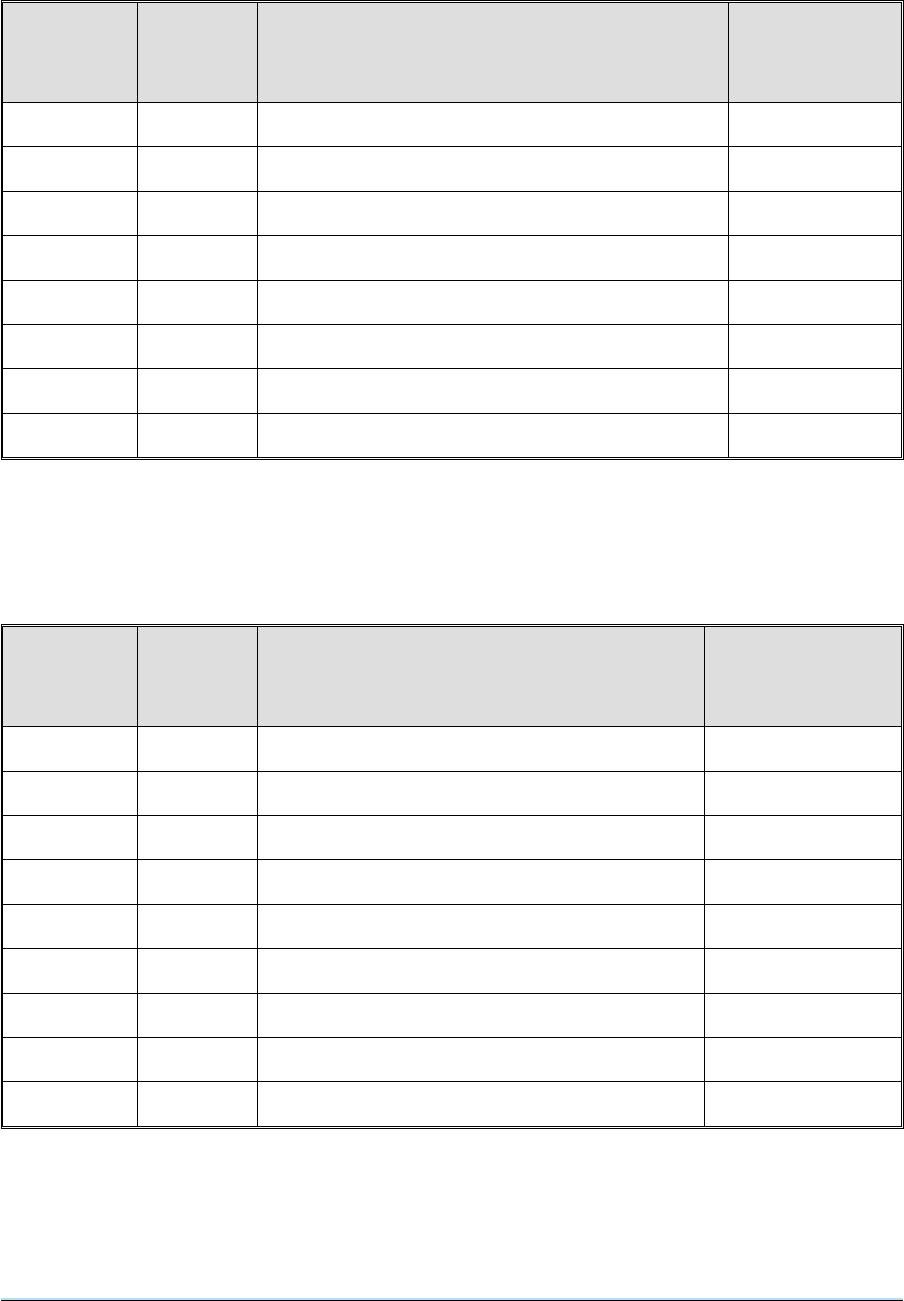
3 Table 3-1 details the internal user adjustments for series 3000DV2 radios with column (3) showing
the manufacturers standard settings. Check that settings applicable to your equipment meet the
required operational conditions.
4 If adjustments are required to be made to the internal standard settings remove the top cover and
locate the appropriate module as indicated in Table 3-1. If the equipment is configured as a desktop or
module installation, the olive green top cover will have to be removed prior to the removal of the
equipment top cover. To access the components locate and loosen the two securing slotted head
screws and withdraw the module. Refitting is the reverse of removal.
3000DV2 Radios Section 3
Page 3
Note that the radio(s) are normally configured to a user’s requirements during manufacture at
Park Air Electronics. Table 3-1 is therefore given for informational purposes only. If there is a need
to alter any settings reference to the appropriate technical handbook(s) may be required.

Table 3-1 3000DV2 Radio Standard Settings
Module/Component
(1)
Function
(2)
Standard Setting
(3)
Tx Control (Module 2)
RV3
RV8
RV6
RV2
RV4
RV1
Link J1
Link J5
Link J2
Link J6
Set tape output
Modulation depth for wideband AM
Modulation depth for wideband FM
Modulation depth for narrow-band
Set mute
Microphone gain
VOGAD
Factory set
Mute
RF drive level detect override
-8 dBm
AM = 80%
FM=20kHz
AM = 80% FM = 5 kHz
1mV
5mV
On
Off
Off
Off
Rx IF and Audio (Module 8)
RV1
RV9
RV7
Link Lk3
Link Lk2
Wideband output level
Mute carrier override
VOGAD threshold level
VOGAD
Noise blanker
-8 dBm for 30% AM
30 µV pd
30% AM
Off
Off
Guard Receiver (Module 4)
(if fitted)
RV9
RV8
Link J1
Link J2
Mute level
Audio line output level
Noise blanker
VOGAD
1µVpd
-8 dBm for 30% AM
Off
Off
Remote Control (Module 5)
(if fitted)
-
-
Links J1 to J11
Line input level
Line output level
Mode configuration
-13 dBm
-13 dBm
Set for required mode of
operation. Refer to the
Remote Control section of
the 3000DV2 Technical
Handbook.
Section 3 3000DV2 Radios
Page 4

MECHANICAL INSTALLATION
5 The equipment can be installed in one of the following ways:
❏On fixed runners within a standard 483 mm (19 inch) equipment rack.
❏On telescopic slides within a standard 483 mm (19 inch) equipment rack.
❏As a desktop equipment by using the PAE free-standing accessory kit.
❏In mobile applications by using the PAE free-standing accessory kit plus an anti-vibration
mount accessory kit.
Caution!
It is essential that the chosen mechanical installation provides adequate support along
the depth (front to rear) of the radio. Under no circumstances must the radio be
supported by the front panel; doing so can cause irreparable damage.
Fixed Runner
6 If using fixed runners, they must provide adequate support along the depth (front to rear), at both
sides of the unit. The unit is secured to the rack through the four front panel fixing holes using suitable
hardware. The front panel fixing holes must not be used at any time to support the equipment.
Telescopic Slides
7 If using telescopic slides, reference should be made to Fig. 5. Four M4 tapped holes, each 10 mm
deep, are provided each side of the equipment for fitting the runners. Dependent on the rack/slide
combination used, it may be necessary to fit a spacer bar between the runner and the equipment. The
width of the spacer must be such that the runners locate correctly within the slide assemblies.
Note ...
Details of suitable telescopic slides are available from PAE.
3000DV2 Radios Section 3
Page 5

Desktop Installation
8 The following installation instructions configure the equipment for desktop operation using a
free-standing accessory kit (PAE part no. 70-3060TR1). With reference to Fig. 6 locate and identify the
components of the free-standing kit.
(a) At the front of the equipment locate and remove the four securing screws from the left and
right rack mounting brackets. Separate the handles from the brackets by removing the two
securing screws. Retain the handles.
(b) Attach the handles, removed in (a), to the left handle plate (item 3) and the right handle plate
(item 2) using the four (two per handle) M5 x 16 mm cap head screws (item 10). Secure the
handle plates to the unit using the eight (four per plate) M4 x 16 mm pan head screws (item 9)
and M4 crinkle washers (item 14).
(c) At the rear of the equipment locate and remove the ten rear panel assembly retaining screws
(item A) and carefully lower the rear panel assembly.
(d) On the left and right-hand side of the PSU compartment locate the four symmetrically placed
holes, note that the two rearmost holes are countersunk. Fit the eight hexagonal M3 x 12 mm
spacers (item 4) to the sides using the four M3x6mmpanhead screws (item 11), four
M3x6mmcountersunk screws (item 8) and eight M4 crinkle washers (item 14).
(e) Raise and secure the rear panel with the ten retaining screws (item A) removed in (c).
(f) Fit the two side covers (item 7) to the hexagonal spacers using the M3x6mmcountersunk
screws (item 8).
(g) Fit the top cover support bracket (item 5) to the rear panel above the filter using the two
M4x6mmpanhead screws (item 12) and crinkle washers (item 14).
(h) Fit the top cover (item 6) using the M3x6mmcountersunk screws (item 8).
(i) On the underside of the equipment locate the four front and rear M4 countersunk crosshead
screws that secure the base plate. Remove the two outer screws from both the front and rear
locations and fit the feet (item 15).
Section 3 3000DV2 Radios
Page 6

Mobile Installation
9 The following instructions configure the equipment for mobile operation using a free-standing
accessory kit (PAE part number 70-3060TR1) and anti-vibration mount accessory kit (PAE part number
70-3060TR2). Before the anti-vibration mounts can be fitted, the equipment must have the free-standing
accessory kit fitted (refer to previous paragraphs detailing desktop installation).
10 Referring to Fig. 7, identify the anti-vibration mount accessory kit components, then complete the
following steps:
(a) Ensure that the free-standing accessory kit is fitted as detailed in the desktop installation
procedures. Fit the front location plate (item 2) to the bottom of the handle blocks of the
equipment using four M4x8mmcskscrews (item 11). The return should be at the front of
the equipment and projecting downwards.
(b) Before fitting the rear location plate (item 5) it is necessary to remove two screws from the
bottom cover as detailed in Fig. 7 (note 3). Fit the rear location plate (item 5) to the bottom of
the equipment using six M4x8mmcskscrews (item 11), ensure that the return projects
upwards.
(c) Fit the four shock mounts (item 9) to the bottom rails (item 10) using 16 M5 x 10 mm csk
screws, nuts and washers (item 4).
(d) Fit the shock mount tray (item 7) to the shock mounts using the four M6 x 20 mm hexagonal
headed screws (item 8).
(e) Using the dimensions detailed on Fig. 7, select a suitable position on the vehicle and mark
out the centres for the fixing holes. Prior to drilling the fixing holes, position the assembled
shock mount tray and ensure that there is sufficient clearance for the equipment when fitted
(allowing for rear panel connectors).
Note ...
The mounting holes can be drilled and tapped M6 and the tray fitted with 16 M6 x 20 mm
hexagonal headed screws (item 12), or drilled out to 6.5 mm and the tray fitted using the
hexagonal headed screws (item 12), nuts and washers (item 13).
(f) Fit the anti-vibration mount assembly into the vehicle and secure firmly.
(g) Attach the two guide pin bushes (item 6) to the equipment mounted rear location plate
(item 5).
(h) Attach the two locating guide pins (item 6), facing forward, to the shock mount tray rear rail
(item 7).
(i) Carefully position the equipment onto the shock mount tray, slide the unit rearward and
ensure that the guide pins and guide pin bushes are securely located. Secure the equipment
to the tray using the three knurled screws (item 3) located on the front location plate (item 2).
3000DV2 Radios Section 3
Page 7

EXTERNAL SELECTIONS AND CONNECTIONS
11 The following external connections must be made to the equipment (dependent on how the
equipment is operated):
❏ac and/or dc supplies.
❏Facilities connections (as required).
❏Remote control (if remote control facility is to be used).
❏Power amplifier or auto-tune filter connection (if required)
❏Antenna.
Note ...
The radio operates from either an ac or dc supply. When both ac and dc are connected, operation
from the ac supply takes priority; automatic change-over to the dc supply will occur if the ac supply
fails. On restoration of the ac supply, the equipment reverts to ac operation.
ac Voltage Selection
12 The equipment can operate with an ac input of 110/120 V or 220/240 V (refer to section 2
specification). The mains voltage selector, fitted under the rear panel top plate must correspond to the
local ac voltage. If the selector’s current setting is incorrect, complete the following steps:
(a) Remove four screws securing the top of the rear panel to the main chassis.
(b) Remove the two securing screws on both the left and right-hand sides of the rear panel and
remove the two screws securing the rear panel to the antenna assembly.
(c) Hinge the rear panel down to expose the mains voltage selector.
(d) Remove the mains selector cover plate.
(e) Set the two switches as required.
(f) Refit the cover plate ensuring that the voltage displayed in the plate’s cut-out agrees with the
required switch setting.
(g) Replace the rear cover using the reverse of the procedure detailed in (a), (b), and (c).
Section 3 3000DV2 Radios
Page 8

Supply Fuses
13 Three fuses are fitted to the equipments rear panel (see Fig. 4):
❏The ac input supply fuse F3 (fitted in the ac input connector).
❏The dc input fuse F1.
❏The dc equipment fuse F2.
14 Noting that different value ac input supply fuses are fitted dependent on the local ac supply, ensure
that the fuses conform to the values detailed in Table 3-2.
Table 3-2 Rear Panel Fuse Ratings
Fuse Rating Size PAE Part Number
Fuse 1
Fuse 2
Fuse 3 (110/120 V)
Fuse 3 (220/240 V)
20 amp. F20A 32 V BS
4 amp. F4A 250 V IEC
8 amp. T8A 250 V IEC
4 amp. T4A 250 V IEC
Size 0 (1¼ inch)
20 mm
20 mm
20 mm
29-01450201
29-01120101
29-01210102
29-01120102
ac Supply Connection
Warnings!
This equipment must be earthed. The earth terminal of the ac connector should be
used as the safety earth.
A chassis stud, marked is fitted to the equipment’s rear panel. This stud is for
connecting the equipment to the equipment rack or user’s system earth point. The
stud is not intended to be used as the safety earth.
15 The ac supply connector is fitted to the radio’s rear panel (see Fig. 4). The minimum rating of the ac
supply cable is: 3-core (to IEC227) rated 250 V ac at 13 amps, and having a minimum cross-sectional
area of 1.25 mm2per core. PAE recommends the use of polyvinyl chloride (PVC) cable. The cable must
be fitted with an IEC approved equipment connector (for example, PAE part number 20-02030102) and
conform to the following specification.
❏If PVC insulated, be not lighter than ordinary polyvinyl chloride sheathed flexible cord
according to IEC publication 227 (designation H05 VV-F, or H05 VVH2-F).
❏If rubber insulated, be of synthetic rubber and not lighter than ordinary tough rubber-sheathed
flexible cord according to IEC Publication 245: Rubber Insulated Cables of Rated Voltages up
to and including 450/750 V, (designation H05 RR-F).
3000DV2 Radios Section 3
Page 9

16 The series 3000DV2 transmitters, receivers and transceivers are Class 1 equipments. The ac
supply cable must have a green-and-yellow protective earthing conductor electrically connected to the
protective earthing terminal of the equipment connector, and the mains plug.
17 PAE recommends the ac supply cable is colour coded in accordance with the electrical appliance
(colour code) regulations for the UK. That is:
Line: Brown
Neutral: Blue
Earth: Green-and-yellow
18 The cores of the power supply cable should be connected to the equipment connector provided,
and your plug as follows:
❏The core that is coloured green-and-yellow must be connected to the terminal in the plug which
is marked with the letter E or by the earth symbol or coloured green-and-yellow.
❏The core that is coloured blue must be connected to the terminal that is marked with the letter N
or coloured black.
❏The core that is coloured brown must be connected to the terminal that is marked with the letter
L or coloured red.
dc Supply Connection
19 The dc supply connector is fitted to the equipment’s rear panel as shown in Fig. 4. The
recommended minimum rating of the dc supply cable is: 2-core, each having a cross-sectional area of
not less than 6.0 mm2per core and fitted with an AMP 3 series connector. The dc supply is connected to
the rear panel DC SUPPLY AXR-PDN style connector, with its associated fuse, as detailed in Table 3-2
and colour coded as follows:
Pin 1 +28 V Red
Pin 2 0 V (ground) Black
Chassis Stud Connection
20 In order not to compromise the equipment’s Electromagnetic Capability (EMC) the chassis stud
marked fitted to the rear panel must be connected to the equipment rack (if a rack is being used) or to
the user’s system earth point. The connection must be made using a single tri-rated, green-and-yellow
cable having a cross-sectional area of 2.5 mm2. The cable should have CSA and UL1015 approval, and
be connected to the chassis stud through an M6 eyelet (for example, PAE part number 20-08010103).
Failure to comply with this instruction could result in non-compliancy with
the European Commission EMC Directive 89/336/EEC.
Section 3 3000DV2 Radios
Page 10

Facilities 2 Connections
21 The facilities 2 connector CN2, fitted to the equipment’s rear panel (refer to Fig. 4), provides a
number of control and monitoring signals that can be configured by the user as required. The connector
pin-outs are detailed in Tables 3-3 to 3-5 and described in the following paragraphs.
22 When making connections to rear panel D-type connector CN2, and in order not to compromise the
equipment’s Electromagnetic Compatibility (EMC), users must:
❏use a D-type connector that has a screened cover.
❏use screened multi-way cable, with the cable’s screen connected to the connector’s shell or
body.
Rx Audio 1 and 2, Wideband Output
23 Pins 1 and 2 provide a 600 ohm balanced wideband data output. The output can be adjusted
between -20 and +10 dBm.
Tx Audio 1 and 2, Wideband Input
24 Pins 3 and 4 provide a 600 ohm balanced wideband data input. The input can be adjusted between
-20 to +10 dBm.
Tape Output
25 Pin 5 provides a 600 ohm single-ended audio output for use with suitable tape recording equipment.
The output contains both the transmit and receive audio.
Guard Mute State
26 Pin 6 provides an active low TTL compatible output when the guard receiver’s (if fitted) mute
threshold is exceeded. This output can be used to indicate when a signal is being received.
PTT State
27 Pin 7 provides an active low TTL compatible output on PTT (pin not used if option 06 fitted).
Guard Rx, Audio 1 and 2 Output
28 The guard Rx audio output, available between pins 8 and 9, provides a 600 ohm balanced audio
output from the guard receiver (if fitted).
Input to Receiver Audio Filter
29 Pins 10 and 11 provide an input to the receiver’s audio filter circuits. These inputs are usually used
to route the plain language output from an external encryption unit, to the receiver’s audio frequency
stages. This facility is not available on standard equipments; advice should be sought from PAE if the
facility is required.
3000DV2 Radios Section 3
Page 11

Mute State Output
30 Pin 12 provides an active low TTL output when the receiver’s mute threshold is exceeded. This
output can be used to indicate when a signal is being received.
DPTT
31 Pin 13 provides a delayed PTT that may be required in Have Quick and/or encryption system
applications.
Hardwire PTT
32 Pin 15 provides a connection for keying the transmitter from an external source (for example, a Link
11 modem). A ground potential on this connection will key the transmitter.
Tx Audio 1 and 2 Narrow-band Input
33 Pins 16 and 17 provide a 600 ohm balanced narrow-band audio input. The input can be adjusted in
the range -20 dBm to +10 dBm.
Rx Audio 1 and 2 Narrow-band Output
34 Pins 18 and 19 provide a 600 ohm balanced narrow-band audio output. The output can be adjusted
in the range -20 dBm to +10 dBm.
Link 11 Tx Audio 1 and 2 Input
35 Pins 20 and 21 provide a 600 ohm balanced input. The input can be adjusted in the range -20 dBm
to +10 dBm.
Link 11 Rx Audio 1 and 2 Output
36 Pins 22 and 23 provide a 600 ohm balanced output. The output can be adjusted in the range
-20 dBm to +10 dBm.
BIT Output
37 Pin 24 is a memory fault output that provides a TTL low potential when the BIT detects a transmitter
or receiver fault. This output can be configured as an equipment fault indicator.
Section 3 3000DV2 Radios
Page 12

Table 3-3 Facilities 2 Connector (CN2) Pin-Out for Transceivers
Pin Function Description
1
2
Rx wideband audio line L1
Rx wideband audio line L2
600 ohm balanced output (adjustable
-20 dBm to +10 dBm for m = 0.9)
3
4
Tx wideband audio line L1
Tx wideband audio line L2
600 ohm balanced input (adjustable
-20 dBm to +10 dBm for m = 0.9)
5Tape output 600 ohm single-ended output. Combined Tx
and Rx audio at -8 dBm (nominal)
6Guard mute state Open collector with 10k pull-up resistor to 5 V
7PTT state (pin 7 not used if
option 06 is selected) Open collector with 10k pull-up resistor to 5 V
8
9
Guard receiver audio line L1
Guard receiver audio line L2
600 ohm balanced audio output from guard
receiver (if fitted) at -8 dBm (adjustable)
10
11
Rx encryption audio input line L1
Rx encryption audio input line L2 For decrypted audio processing
12 Mute state output Active low TTL output
13 DPTT Delayed PTT input
14 Not used -
15 Hardwire PTT 0 volt input keys transmitter
16
17
Tx narrow-band audio line L1
Tx narrow-band audio line L2
600 ohm balanced input (adjustable
-20 dBm to +10 dBm for m = 0.9)
18
19
Rx narrow-band audio line L1
Rx narrow-band audio line L2
600 ohm balanced output (adjustable
-20 dBm to +10 dBm for m = 0.9)
20
21
Link 11 Tx audio line L1 (UHF only)
Link 11 Tx audio line L2 (UHF only)
600 ohm balanced Link 11 audio input
(adjustable -20 dBm to +10 dBm for
F = 20 kHz)
22
23
Link 11 Rx audio line L1 (UHF only)
Link 11 Rx audio line L2 (UHF only)
600 ohm balanced Link 11 audio output
(adjustable -20 dBm to +10 dBm for
F = 20 kHz)
24 BIT output Memory fault output. Active low TTL
25 0 volt Ground
3000DV2 Radios Section 3
Page 13

Table 3-4 Facilities 2 Connector (CN2) Pin-Out for Receivers
Pin Function Description
1
2
Rx wideband audio line L1
Rx wideband audio line L2
600 ohm balanced output (adjustable
-20 dBm to +10 dBm for m = 0.9)
5Tape output 600 ohm single-ended output. Rx audio at
-8 dBm (nominal)
6Guard mute state Open collector with 10k pull-up resistor to 5 V
8
9
Guard receiver audio line L1
Guard receiver audio line L2
600 ohm balanced audio output from guard
receiver (if fitted) at -8 dBm (adjustable)
10
11
Rx encryption audio input line L1
Rx encryption audio input line L2 For decrypted audio processing
12 Mute state output Active low TTL output
18
19
Rx narrow-band audio line L1
Rx narrow-band audio line L2
600 ohm balanced output (adjustable
-20 dBm to +10 dBm for m = 0.9)
22
23
Link 11 Rx audio line L1 (UHF only)
Link 11 Rx audio line L2 (UHF only)
600 ohm balanced Link 11 audio output
(adjustable -20 dBm to +10 dBm for
F = 20 kHz)
24 BIT output Memory fault output. Active low TTL
25 0 volt Ground
Section 3 3000DV2 Radios
Page 14
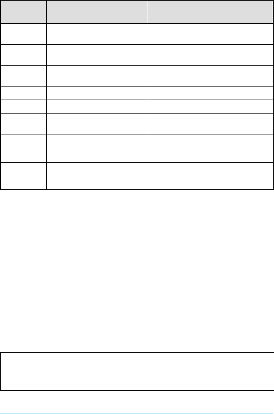
Table 3-5 Facilities 2 Connector (CN2) Pin-Out for Transmitters
Pin Function Description
3
4
Tx wideband audio line L1
Tx wideband audio line L2
600 ohm balanced input (adjustable
-20 dBm to +10 dBm for m = 0.9)
5Tape output 600 ohm single-ended output. Tx audio at
-8 dBm (nominal)
7PTT state (pin 7 not used if
option 6 is selected) Open collector with 10k pull-up resistor to 5 V
13 DPTT Delayed PTT input
15 Hardwire PTT 0 volt input keys transmitter
16
17
Tx narrow-band audio line L1
Tx narrow-band audio line L2
600 ohm balanced input (adjustable
-20 dBm to +10 dBm for m = 0.9)
20
21
Link 11 Tx audio line L1 (UHF only)
Link 11 Tx audio line L2 (UHF only)
600 ohm balanced Link 11 audio input
(adjustable -20 dBm to +10 dBm for
F = 20 kHz)
24 BIT output Memory fault output. Active low TTL
25 0 volt Ground
Remote PTT Configurations
38 Remote PTT configurations (reference transceivers and transmitters) are shown in Fig. 3-1 and are
as follows:
❏dc Phantom keying (Low to PTT)
❏dc Phantom keying (High to PTT)
❏ac Tone keying
❏Direct keying (Low to PTT)
❏Direct keying (High to PTT)
39 Connections shown in Fig. 3-1 are to the transceivers facilities 2 connector CN2. Additionally,
phantom keying and ac tone keying can be configured through the remote connector CN5. If using this
method, use those connections shown in Fig. 3-1 that are in brackets. All links and circuitry shown are on
the remote control module.
3000DV2 Radios Section 3
Page 15
Note that the radio(s) are normally configured to a user’s requirements during manufacture at
Park Air Electronics. PTT configurations are therefore given for informational purposes only. If
there is a need to alter any settings reference to the appropriate technical handbook(s) may be
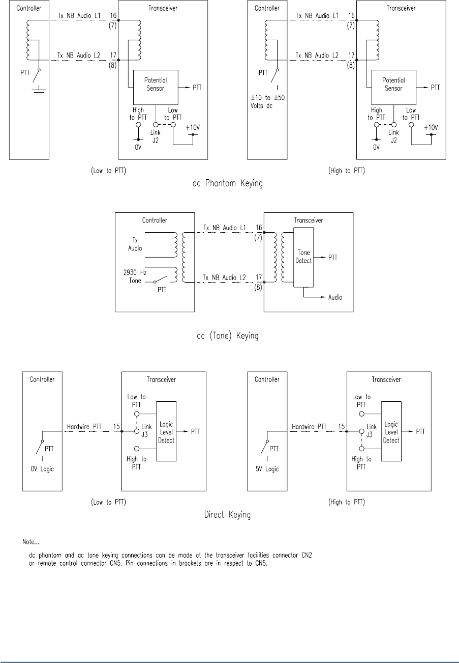
Fig. 3-1 Remote Interface PTT Configurations
Section 3 3000DV2 Radios
Page 16

Remote Control Connections
40 As an alternative to local operation, the equipment can be operated from a remote position using a
PAE 3000V2 Series Remote Control Unit (RCU). Connections to the RCU are made from the radio’s
rear panel 9-way D-type remote connector CN5 (see Fig. 4).
41 The pin-out of the remote connector is detailed in Table 3-6. Pins 1 to 4 and 9 are used by all
models; pins 5 and 6 by transceivers and receivers only, and pins 7 and 8 by transceivers and
transmitters only.
42 When making connections to rear panel D-type connectors, and in order not to compromise the
equipment’s Electromagnetic Compatibility (EMC), users must:
❏use a D-type connector that has a screened cover.
❏use screened multi-way cable, with the cable’s screen connected to the connector’s shell or
body.
Table 3-6 Remote Connector (CN5) Pin-Out
Pin Function Description
AC Control DC Control
1
2
3
4
Transmit data
Transmit data
Receive data
Receive data
CCITT V23 serial interface
over ac lines with maximum
line loss of 17 dB
Serial RS422 interface for
operation up to 2 km when
used with PAE 3000V2 Series
Remote Control Unit (RCU)
5
6
Receive audio line L1
Receive audio line L1
4-wire operation. 600 ohm
nominal.
Operating line level with
Automatic Level Control
(ALC) is -13 dBm.
PTT signal is a 2930 Hz
tone superimposed on the
audio circuit.
Line output adjustable
between -20 dBm and
+10 dBm
7
8
Transmitter audio line L1
Transmitter audio line L2
Line input adjustable
between -20 dBm and
+10 dBm
90 volt connection Ground Ground
3000DV2 Radios Section 3
Page 17
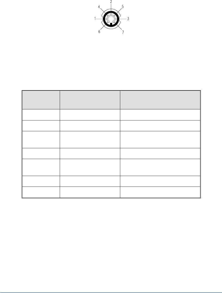
Microphone/Headset Connection
43 To operate the equipment in local mode using the front panel, a suitable microphone/headset, or
headset is connected to the front panel’s MIC/HEADSET connector. The connectors location is shown
in Figs. 7 to 9 and the connector’s pin-outs are detailed in Table 3-7 to 3-9. Fig. 3-2 shows the
connector’s pin-out.
Table 3-7 Transceiver Mic/Headset Connector Pin-Out
Pin Function Description
1Microphone ground Microphone return
2Not used -
3PTT Local PTT line (0 volt keys
transmitter)
4Not used -
5Sidetone Receive + Transmit audio to
headset. 100 mW into 100 ohm.
6Microphone live 600 ohm. 3 mV to 30 mV
70 volt PTT grounding signal
Section 3 3000DV2 Radios
Page 18
Fig. 3-2 Mic/Headset Connector Pin-Out
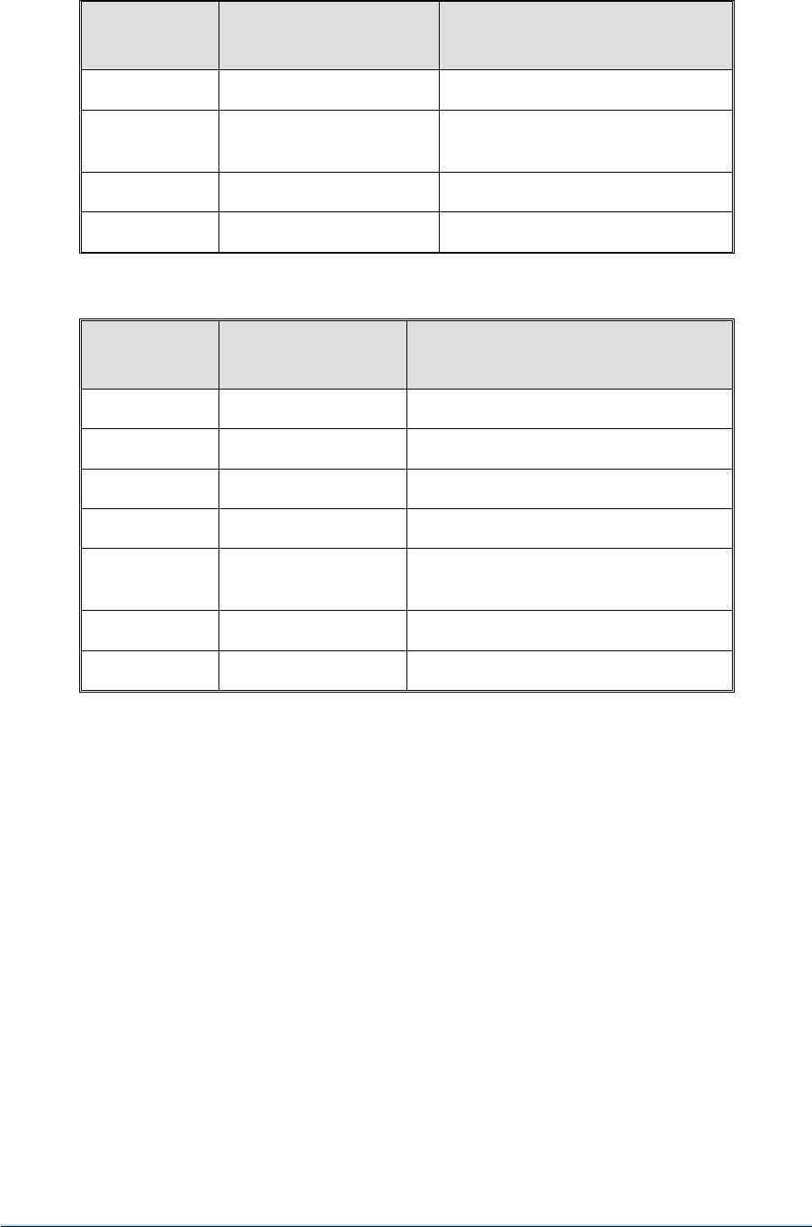
Table 3-8 Receiver Mic/Headset Connector Pin-Out
Pin Function Description
1to4 Not used -
5Receiver audio Receiver audio to headset.
100 mW into 100 ohm.
6Not used -
70 volt Ground
Table 3-9 Transmitter Mic/Headset Connector Pin-Out
Pin Function Description
1Microphone ground Microphone return
2Not used -
3PTT Local PTT line (0 volt keys transmitter)
4Not used -
5Sidetone Transmit audio to headset.
100 mW into 100 ohm.
6Microphone live 600 ohm. 3 mV to 30 mV
70 volt PTT grounding signal
PA/Filter Drive Connection (Option 06)
44 With this option, the 37-way D-type connector CN3 on the rear panel (refer to Fig. 4) is used to
interface the radio to an external auto-tune filter or power amplifier (such as a PAE 3640). The pin-out of
the connector is detailed in Table 3-10.
45 When making connections to the rear panel D-type connector CN3, and in order not to compromise
the equipment’s Electromagnetic Compatibility (EMC), users must:
❏use a D-type connector that has a screened cover.
❏use screened multi-way cable, with the cable’s screen connected to the connector’s shell or
body.
Note ...
When the optional Have Quick module is fitted in the radio, the function of connector CN3 pins 24
and 25 changes. These changes are detailed in Table 3-10. Note also the radio's front panel PCB
DIP switch SW1-5 must be correctly set: On when a Have Quick module is fitted; Off when a Have
Quick module is not fitted.
3000DV2 Radios Section 3
Page 19

Table 3-10 Power Amplifier/Auto-Tune Filter Connections at CN3
Pin Condition Function
1
2
3
4
5
6
7
8
9
10
11
12
13
14
15
16
17
18
19
20
21
22
23
24
25
26
27
28
29
30
31
32
33
34
35
36
37
TTL
TTL
TTL
TTL
TTL
TTL
TTL
TTL
TTL
TTL
TTL
Not used
Not used
Not used
0 volt
0 volt
0 volt
0 volt
TTL
TTL
TTL
TTL
TTL
TTL
TTL
TTL
TTL
TTL
TTL
TTL
TTL
TTL
Not used
Not used
28Vdc
28Vdc
28Vdc
25 kHz
50 kHz
100 kHz
200 kHz
400 kHz
800 kHz
1 MHz
2 MHz
4 MHz
8 MHz
Amplifier present
-
-
-
0 volt
0 volt
0 volt
-
Filter detect
10 MHz
20 MHz
40 MHz
80 MHz
100 MHz (HQ module fitted: 200/300 MHz. High = 300 MHz selected)
200 MHz (HQ module fitted: No connection)
Filter tune
VHF/UHF state
AM/FM state
EBIT
Reset bypass/HQ AJ state
Inhibit
Fast PTT
-
-
28Vdc
28Vdc
28Vdc
Note ...
The frequency output pins (pins 1-10 and 20-25) are positive logic and represent the
current frequency of the radio. For example if the radio was operating on 225.000 MHz,
CN3 pins 7, 9, 21 and 25 would be logic high.
Section 3 3000DV2 Radios
Page 20

External Clock
46 The rear panel connector CN4 (see Fig. 4) is for use with transceivers with the Have Quick option
that require an external clock. The connector allows an external timing source to be connected (see
Table 3-11).
47 When making connections to the rear panel D-type connector CN4, and in order not to compromise
the equipment’s Electromagnetic Compatibility (EMC), users must:
❏use a D-type connector that has a screened cover.
❏use screened multi-way cable, with the cable’s screen connected to the connector’s shell or
body.
Table 3-11 External Clock Interface Connector (CN4) Pin-Out
Pin Number Signal Function
1
2
3
4
5
6
7
8to15
Ext +5V In
Ext TOD Out
Ext CLK In
Ext CLK Shield
Ext TOD In
Gnd
Ext CLK En
Not used
+5 volt external oscillator supply
External TOD output
External clock input
External clock 0 volt/screen
External time-of-day input
0 volt signal return
External clock enable input
-
Unused Connection CN6
48 Connector CN6 is fitted on the rear panel, but is reserved for future development.
Antenna Connection
Warning!
Antennas used with 3000DV2 transmitters and transceivers must be installed such
that the resultant radiated field strength is below 10 watt per square metre in areas
normally accessible to personnel.
49 The antenna is connected through the appropriate rear panel VHF and/or UHF ANTENNA N-type
coaxial connectors, (see Fig. 4). Connection to the antenna sockets should be made using coaxial cable
type RG213 (PAE accessory part no. 10-05120600) fitted with the appropriate N-type plug (PAE part no.
19-01030301), see Fig. 8 for assembly details.
50 An alternative coaxial cable (PAE accessory part no. 10-05120200) with equivalent or better loss
and power handling characteristics, fitted with an appropriate N-type plug (PAE part no. 19-01030306),
can be used. Ensure that any coaxial cable connected to the equipment has a characteristic impedance
of 50 ohms.
3000DV2 Radios Section 3
Page 21

SETTING-UP
51 If available the following test equipment is recommended for carrying out the setting-up instructions:
RF Power Meter
or
Dummy Load
Note ...
When making key entries during the following procedures, do not pause more than 5 seconds
between key strokes or new data will be lost and the system will revert to default settings.
PRELIMINARY CHECKS
52 Prior to the application of ac and/or dc supplies, ensure that the front panel AC and DC SUPPLY
switches are in their OFF positions (down). Carry out a physical check of the transmitter verifying the
following:
❏All connections and connectors are secure.
❏All cable assemblies are properly supported.
❏No cable is trapped or kinked.
❏The transmitter/receiver is secured in its operational position.
❏Tools used during installation have been removed.
❏The impedance of the antenna feed cable is correct.
❏The supply voltages and ratings are correct.
53 If available connect a suitable RF power meter or dummy load to the appropriate rear panel N-type
ANTENNA connector.
Warning ...
On application of ac and/or dc supplies lethal voltages are present within the
equipment. Care must be taken by personnel to avoid contact with exposed circuitry
during any setting-up or maintenance procedures.
Section 3 3000DV2 Radios
Page 22

SWITCHING ON, AND AC AND DC CHANGE-OVER CHECKS
54 If both ac and dc supplies are connected to the equipment carry out the following change-over
check:
(a) At the front panel, set both AC and DC SUPPLY switches to on. Confirm that both AC and
DC SUPPLY indicators, located on the front panel, are lit.
(b) Isolate the radio from the ac supply and confirm that the following conditions exist:
AC SUPPLY indicator is unlit.
DC SUPPLY indicator is lit.
Frequency display shows a frequency.
(c) Restore the ac supply to the equipment and confirm that both SUPPLY indicators are lit.
When both ac and dc supplies are present the equipment will automatically select the ac
supply.
55 If only one supply is used, set the appropriate front panel SUPPLY switch to its on position and
confirm that the SUPPLY indicator above the switch is lit. Check also that the frequency display shows a
frequency.
SELECTING OPTIONS
56 Options available on a radio are described in section 1 of this handbook. Before becoming
operational, the options must be selected at the radio’s front panel. How to do this is fully described in
section 4 on page 21. No options become operational until this procedure has been completed.
SET RADIO ID
57 If the radio is to be used as part of a system, controlled remotely by an RCU, it must be identified by
its own unique ID that is a number in the range 0 and 254.
Key sequence: ID number, SHIFT s,8
Example. Setting the Radio’s ID
58 To set the ID to 2, enter the following key sequence:
2, SHIFT s,8
59 Error 38 is displayed if an invalid ID is entered.
3000DV2 Radios Section 3
Page 23

VIEW RADIO ID
60 The previous sequence can be used to both set, and view, the current ID of a radio. If a number
does not prefix the key sequence then the ID is displayed for 5 seconds, but can be cancelled before the
5 seconds have elapsed by pressing the CE key.
Example. Viewing the Radio’s ID
61 To view the current ID, enter the following key sequence:
SHIFT s,8
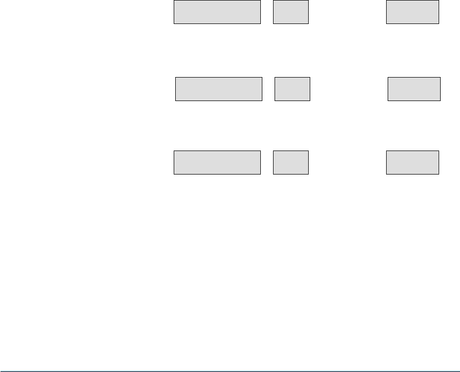
62 The radio’s front panel displays show the ID as shown below.
SET EQUIPMENT BAUD RATE
63 If the radio is to be remotely controlled at a baud rate other than the default 1200 rate, a key
sequence can be entered to select the required baud rate. Valid baud rates are: 1200, 2400, 4800 and
9600.
Key sequence: baud rate, SHIFT s,9
64 Error 38 (Err 38) is displayed if an invalid baud rate is selected.
Example. Setting the Baud Rate
65 To set the baud rate to 9600, enter the following key sequence:
9600, SHIFT s,9
VIEW EQUIPMENT BAUD RATE
66 The previous sequence is used to set, and view, the baud rate of the radio being remotely
controlled. If a number does not prefix the key sequence, the current baud rate setting is displayed for 5
seconds, but can be cancelled before the 5 seconds have elapsed by pressing the CE key.
Example. Viewing the Current Baud Rate
67 To view the current ID, enter the following key sequence:
SHIFT s,9
The radio’s front panel displays show the baud rate as illustrated below.
Section 3 3000DV2 Radios
Page 24
002 Id
FREQUENCY CHANNEL MONITOR
9600 -- bAUd
FREQUENCY CHANNEL MONITOR
VIEW BAND EDGES
68 The highest and lowest frequencies that a radio can operate on are called the band edges. These
can be viewed using the following key sequences:
SHIFT s, 4 View band edge 1 (lowest VHF frequency)
SHIFT s, 5 View band edge 2 (highest VHF frequency)
SHIFT s, 6 View band edge 3 (lowest UHF frequency)
SHIFT s, 7 View band edge 4 (highest UHF frequency)
69 Viewing band edges 1 and 2 is only available on VHF equipments and viewing band edges 3 and 4
is only available on UHF equipments. VHF/UHF radios, for example the 3060V2 transceiver, can display
all band edges.
70 Band edges cannot be programmed, only viewed. Following each valid key sequence the display
shows the band edge for five seconds. The display can be returned to normal before 5 seconds have
elapsed by pressing the CE key.
Example. Viewing a Band Edge
71 To view band edge 1 (lowest VHF frequency that in this example is 100 MHz) enter key sequence
SHIFT s, 4. The radio’s displays are shown below.
3000DV2 Radios Section 3
Page 25
325.000 21
FREQUENCY CHANNEL MONITOR
Before key sequence, displays show
operating frequency and channel
100 E1
FREQUENCY CHANNEL MONITOR
Enter key sequence, SHIFT s,4
325.000 21
FREQUENCY CHANNEL MONITOR
After five seconds, or if the CE key is
pressed, displays show original values

FUNCTIONAL CHECKS
72 The following checks are for transceivers and transmitters only. At the front panel TX control pad
set the FWD button to its on position, indicated by the associated indicator being lit (refer to Figs. 1
and 2). Operate the PTT button (red) and confirm that a reading of approximately 40 W (AM) or 60 W
(FM) is indicated on the front panel MONITOR display, unless connected to a serviceable 3640 power
amplifier in which case a reading of approximately 40 W AM and FM is indicated.
73 Connect a microphone (with integral PTT switch) to the front panel MIC/HEADSET socket, set the
MOD button to its on position, operate the PTT and speak into the microphone (maintaining a constant
tone). Confirm that a reading of greater than 30(%) is indicated in the MONITOR display, release the
PTT switch.
74 Remove the dummy load and reconnect the antenna. Carry out an interruptive BIT test as detailed
in section 4, operating instructions.
Section 3 3000DV2 Radios
Page 26

Operation
Contents
Paragraph
1INTRODUCTION
FRONT PANEL CONTROLS AND INDICATORS
3 Front panel layout
4 Transmitter (Tx) controls and indicators
11 Receiver (Rx) controls and indicators
19 Synthesiser controls and indicators
41 Mainframe controls and indicators
50 Auxiliary controls
55 Rear panel connections
SETTING-UP AND OPERATING PROCEDURES
63 Switching on
64 Frequency selection
65 Channel frequency setting
67 Channel recall
68 Channel verification
69 8.33 kHz channel operation
72 Frequency selection for 8.33 kHz channel spacing
73 Channel frequency setting for 8.33 kHz channel spacing
75 System reset
77 Auto-calibrate
78 Guard receiver operation
81 Options, software versions, and radio type menus
83 Options
88 Viewing software versions
89 Radio type menu
90 Screen blanking
93 Transmit operation (for transmitters and transceivers only)
97 Receive operation (for receivers and transceivers only)
MARITIME BAND - ADDITIONAL OPERATING INFORMATION
100 General
101 Normal mode
102 Ship/Shore modes
105 Ship/shore view modes
106 Channel change
107 Frequency change
108 External RF filter
109 Key sequences
3000DV2 Radios Section 4
Page 1

110 BUILT-IN TEST (BIT) OPERATION
111 Power on self test
117 Continuously monitored functions
119 Interruptive self-test routine
122 Fault memory
USER MAINTENANCE
125 Filter cleaning
126 Lamp test
127 Frequency accuracy check
Table Page
4-1 8.33 kHz channel spacing - special frequency designations 17
4-2 Options, software versions and radio type menus 21
4-3 Maritime function key sequences 28
4-4 Maritime frequencies 29
4-5 Error message codes 34
Section 4 3000DV2 Radios
Page 2

INTRODUCTION
1 This section details the radio’s controls and indicators, and explains how to operate the equipment
using the front panel controls. All of this section is applicable to 3000DV2 transceivers. Series 3000DV2
transmitter and receiver users should only read those parts of this section applicable to their type of
equipment.
2 As an alternative to operating the equipment using the front panel controls, a suitable Remote
Control Unit (RCU) can be employed. Although the RCU replicates many of the equipment’s front panel
controls and indicators, reference should always be made to the operating instructions supplied with the
RCU.
FRONT PANEL CONTROLS AND INDICATORS
FRONT PANEL LAYOUT
3 For the purposes of describing the controls and indicators, the front panel can be divided into the
following five sections (see Figs. 1, 2, and 3). Each section is described in the following paragraphs.
❏Transmitter (Tx) controls and indicators.
❏Receiver (Rx) controls and indicators.
❏Synthesiser controls and indicators.
❏Mainframe controls and indicators.
❏Auxiliary controls and indicators.
3000DV2 Radios Section 4
Page 3
Transmitter (Tx) Controls and Indicators
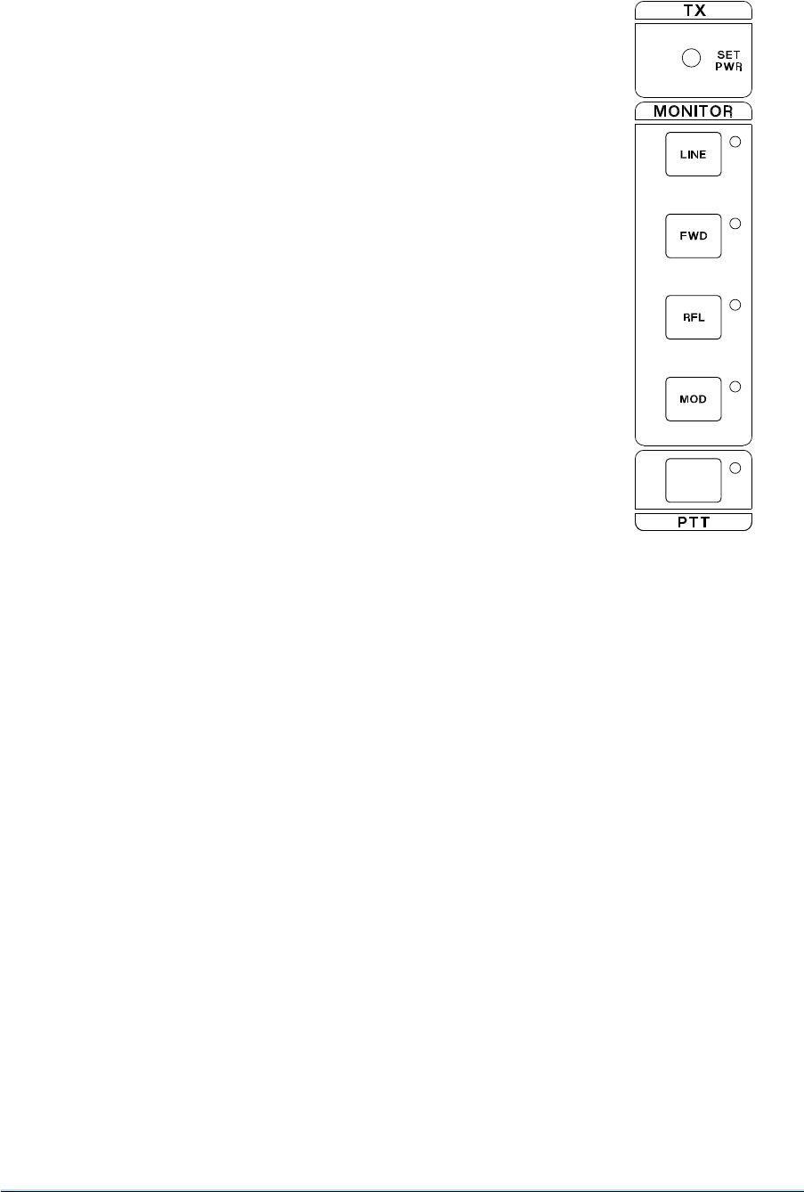
4 The transmitter’s controls and indicators (see Fig. 4-1) comprise a
SET PWR control, PTT switch and the four monitor switches LINE, FWD,
RFL and MOD. It should be noted that only one monitor function can be
selected at any one time; to deselect a selected function, press the
selected function switch or select the other function or press the RESET
switch.
SET PWR
5 The maximum output power from the transmitter is 40 W (AM) or
60 W (FM). The set power control allows a reduction of output power
between 0 and 10 dB. Note that when the radio is connected to a PAE
3640 power amplifier, the FM output is reduced to 40 W.
PTT
6 A momentary action press-to-operate switch: When the switch is
pressed, the transmitter becomes keyed, and the adjacent indicator lights.
LINE
7 Two-position push-to-select (push again to deselect) line monitor
switch. When selected, the adjacent indicator is lit and the front panel
monitor display shows the transmitter’s line input level (in dBm).
FWD
8 Two-position push-to-select (push again to deselect) forward power monitor switch. When
selected, the adjacent indicator is lit and the front panel monitor display shows the transmitter’s forward
output power (in watts).
RFL
9 Two-position push-to-select (push again to deselect) reflected power monitor switch. When
selected, the adjacent indicator is lit and the front panel monitor display shows the transmitter’s reflected
output power (in watts).
MOD
10 Two-position push-to-select (push again to deselect) modulation depth monitor switch. When
selected, the adjacent indicator is lit and the front panel monitor display shows the transmitter’s
modulation depth (as a % when AM is selected, or in kHz when FM is selected).
Section 4 3000DV2 Radios
Page 4
Fig. 4-1
Transmitter Controls
Receiver (Rx) Controls and Indicators
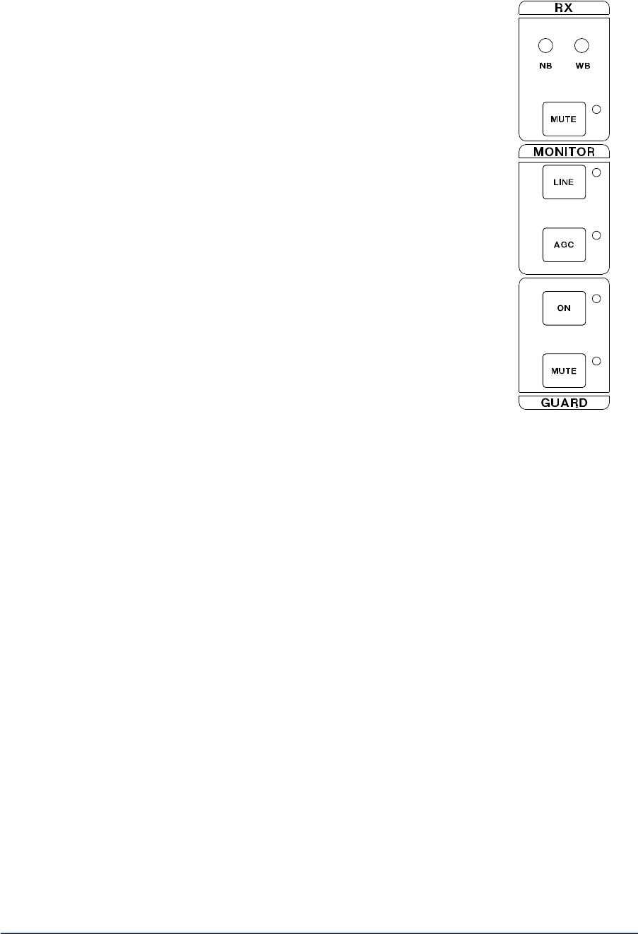
11 The receiver’s controls and indicators (see Fig. 4-2) comprise a SET
MUTE (narrow-band) and SET MUTE (wideband) controls, MUTE control,
two monitor switches LINE and AGC, and guard receiver controls ON and
MUTE. It should be noted that only one of the two monitor functions can be
selected at any one time; to deselect a selected function, press the selected
function switch or select the other function or press the RESET switch.
SET MUTE (Narrow-band)
12 The set mute (narrow-band) control allows the receiver’s mute
threshold to be adjusted between a 6 dB and 16 dB signal-to-noise (S+N:N)
ratio.
SET MUTE (Wideband)
13 The set mute (wideband) control allows the receiver’s mute threshold to
be adjusted over the RF input range 1.5 mV to 50 mV emf.
MUTE
14 Two-position push-to-select (push again to deselect) mute defeat
switch. When in the defeat position, the adjacent indicator is lit, and the
receiver’s mute circuit is disabled. When the switch is in the other position,
the indicator lights when audio is present, and the mute circuit operates at
the threshold determined by the SET MUTE control operative at the time.
LINE
15 Two-position push-to-select (push again to deselect) line monitor switch. When selected, with the
receiver operational, the adjacent indicator is lit and the front panel monitor display shows the receiver’s
line output level (in dBm).
AGC
16 Two-position push-to-select (push again to deselect) AGC monitor switch. When selected, the
adjacent indicator is lit and the front panel monitor display shows the receiver’s automatic gain control
(AGC) level (in volts).
GUARD ON
17 Two-position push-to-select (push again to deselect) switch. This switch is only operational when
the guard option is fitted. When selected, the adjacent indicator is lit and the guard receiver audio can be
monitored on the loudspeaker or headphones (if connected). The presence of audio is dependent on
the guard receiver’s mute status.
GUARD MUTE
18 Two-position push-to-select (push again to de-select) guard mute defeat switch. When in the
defeat position, the adjacent indicator is always lit, and the guard receiver’s mute circuit is disabled.
When the switch is in the other position, the indicator lights when audio is present and the mute circuit is
operational.
3000DV2 Radios Section 4
Page 5
Fig. 4-2
Receiver Controls
Synthesiser Controls and Indicators
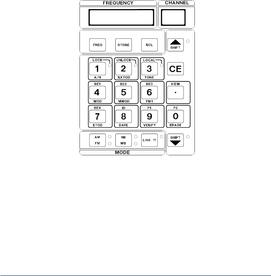
19 The synthesiser controls and indicators panel (see Fig. 4-3) comprises:
❏A frequency and a channel display.
❏A triple function keypad providing primary, secondary and tertiary key functions. The primary
function of the keypad is engraved on the key(s) (0-9). The keys allow frequencies and
channels to be entered and stored in the equipment’s memory, and provide for the selection of
different display functions. Keys with lettering above them provide a second function and
provide the means by which a number of operational functions are carried out. Keys with
lettering below them have a third function that is used in sets when option 07 (Have Quick) or
option 12 (Quick Fox) is fitted.
❏Three mode selection keys: AM/FM, Narrow-band/Wideband (NB/WB) and Link 11.
Section 4 3000DV2 Radios
Page 6
Fig. 4-3 Synthesiser Controls

FREQUENCY and CHANNEL Displays
20 The synthesiser provides a six-digit frequency display and a two-digit channel display. The displays
have four functions:
❏Monitor Function. The displays show the current operating frequency and channel number.
❏Edit Function. The edit function is indicated by a flashing decimal point at the bottom
right-hand end of the frequency display. Edit function shows information being entered from
the keypad, not the radio’s current operating parameters.
❏View Function. View facilities allow channel information to be displayed without affecting the
operation of the radio. This can be used, for example, to check the frequencies stored in each
of the 99 pre-set channels; during such checks, the radio’s operating frequency does not
change.
❏Error Message Function. Error messages are automatically displayed if invalid keypad
entries are made, or when certain fault conditions are detected. Error messages are detailed in
Table 4-5 on page 34.
Second Function Select Key
21 The second function select key (SHIFT s) is a push-to-select, push again to de-select key, that
selects either the primary or second function of the keypad. When second function is selected, the
adjacent indicator is lit. When primary function is selected, the adjacent indicator is unlit.
Third Function Select Key
22 The third function select key (SHIFT t) is a push-to-select, push again to de-select key, that selects
either the primary or third function of the keypad. When third function is selected, the adjacent indicator
is lit. When primary function is selected, the adjacent indicator is unlit.
Numerical Data Keys 0 through 9
23 Primary function data keys 0 through 9 are used to enter numeric data.
Decimal Point Key
24 The primary function decimal point key, adds a point to the right of the last number entered. If this is
the first key entry, the display will blank and a 0 (zero) followed by a decimal point will be entered in the
first position.
Cancel Entry (CE) Key
25 The primary function CE key cancels previous selections as follows:
❏If the previous selection was a numeric data key, the last digit entered will be replaced by a
blank. Further use of the CE key progressively removes remaining digits from the display;
pressing the CE key when only one digit is shown causes the display to go to the monitor
mode.
❏If the previous key entry resulted in an error code (refer to Table 4-5), pressing the CE key
restores the settings shown before the previous key entry.
❏If the previous entry was as a function key, then the key entry is ignored.
3000DV2 Radios Section 4
Page 7

Frequency (FREQ) Key
26 Pressing this key causes the equipment’s operating frequency to change to that shown on the
frequency display, if the displayed frequency is valid. Pressing this key does not alter any stored
channels. Entering a valid frequency results in the frequency being shown in the frequency display, and
the channel display being blanked.
27 If the entered frequency falls outside the band edge frequencies an error message (refer to
Table 4-5) is displayed and the operational frequency is not changed. The error message is cancelled by
pressing the CE key.
Channel Store (STORE) Key
28 In edit mode, when a valid channel number is displayed in the frequency display and the store key is
pressed, the following settings will be stored with the channel number:
❏Frequency
❏AM or FM selection
❏Narrow-band or wideband selection
❏Link 11 selection.
29 Entering an invalid channel number will result in an error message. Pressing the CE key will
remove the error message.
Channel Recall (RCL) Key
30 The channel recall key is used to recall pre-set frequencies and associated settings. Entering a
valid channel number, and pressing the recall key, resets the equipment’s frequency, AM/FM selection,
narrow/wideband selection and Link 11 selection. If the recalled channel number contains no previously
stored data, the key entry will be ignored.
LOCK Key
31 The LOCK key (second function) disables all functions except the Unlock Key, PTT and monitor
functions. When lock is selected, the adjacent indicator is lit.
UNLOCK Key
32 The unlock key (second function) returns the keypad from the locked condition and enables normal
operation. When the unlock condition is selected, the adjacent indicator is lit.
LOCAL Key
33 The local key (second function) is not used.
VIEW Key
34 Used to verify channel information. When a channel has been selected and the view key
(secondary function) is pressed, all stored information appropriate to the selected channel is displayed
without changing the operational parameters of the equipment. The display will show the viewed channel
for 5 seconds before returning to the monitor mode.
Section 4 3000DV2 Radios
Page 8

P1 Key
35 The P1 key (second function) is used to set or view the remote operation baud rate during initial
installation (see section 3) or following replacement of the radio.
P2 Key (Lamp Test)
36 The P2 key (second function) enables a lamp test to be performed on all LEDs and lamps on the
front panel allowing the operator to test for unserviceable LEDs/lamps. The test lasts for 5 seconds, or
less if the CE key is pressed. Note that the AC and DC supply lamps are not tested as part of this test.
AM/FM Mode Key
37 This primary function key is used to select either AM or FM operating mode. Two indicators are
fitted to the right of the key. When AM is selected, the upper indicator will be lit; when FM is selected, the
lower indicator will be lit. Note that FM cannot be selected if an 8.33 kHz channel is being used. If it is
selected, an error message is displayed (see Table 4-5 on page 34).
NB/WB Mode Key
38 The NB/WB (primary function) key is used to select either narrow or wideband mode of operation.
Two indicators are fitted to the right of the key. When narrow-band is selected, the upper indicator will be
lit; when wideband is selected, the lower indicator will be lit. Note that WB cannot be selected if an
8.33 kHz channel is being used. If it is selected, an error message is displayed (see Table 4-5 on
page 34).
LK11 Key
39 The Link 11 key (primary function) is used to switch the equipment between normal and Link 11
modes of operation. When Link 11 mode is selected, the upper indicator, to the right of the key, will be lit.
When normal mode is selected, the upper indicator will be unlit.
40 When Link 11 is selected, FM, wideband, and short AGC modes of operation are automatically
selected. The mode is disabled when the AM/FM or NB/WB key is pressed. Note that Link 11 cannot be
selected if an 8.33 kHz channel is being used. If it is selected, an error message is displayed (see
Table 4-5 on page 34).
3000DV2 Radios Section 4
Page 9
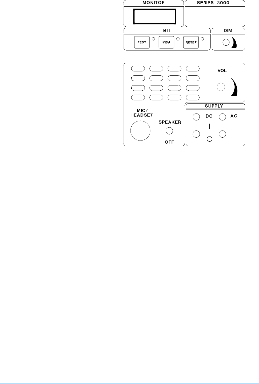
Mainframe Controls and Indicators
41 The mainframe controls and
indicators (see Fig. 4-4) comprise a
monitor display, BIT controls, audio
controls, and supply on/off switches.
BIT TEST Key
42 The test key is used to start an
interruptive self-test routine. During this
routine, normal operation of the equipment
is suspended and the test indicator
flashes. Details of this test routine can be
found in this section under the heading:
Built-in Test (BIT) operation.
BIT MEM Key
43 The memory (mem) key is used to
indicate the contents of the equipment’s
fault memory store. Successive presses of
the memory key displays (in the monitor
display) fault conditions found during BIT
routines. Details of the fault memory can
be found in this section under the heading:
Built-in Test (BIT) operation.
BIT RESET Key
44 The reset (RESET) key is used to clear the monitor display. The second function (s), RESET key
sequence clears the BIT memory. The second function (s), RESET key sequence also resets the
bypass of a 3640 power amplifier if in fault and Ebit displayed, this will put the 3640 back into normal
mode once the fault on the 3640 is cleared.
DIM Control
45 A rotary control that adjusts the brilliance of the front panel indicators. This control should be
adjusted for optimum brilliance according to ambient lighting conditions.
VOL Control
46 Turning the volume control clockwise increases the volume of the received audio at the speaker or
headset dependent upon the setting of the speaker/headset switch.
MIC/HEADSET Connector
47 A seven-pin connector that allows a microphone/headset to be connected. Details of the pin-outs
can be found in section 3 of this handbook.
Speaker/Off switch
48 When in the SPEAKER position selects the loudspeaker to receive the audio output of the receiver.
In this position Tx sidetone is not available on the mic/headset socket. In the OFF position the
mic/headset socket headphone output receives the audio output of the receiver and Tx sidetone.
Section 4 3000DV2 Radios
Page 10
Fig. 4-4 Mainframe Controls and Indicators
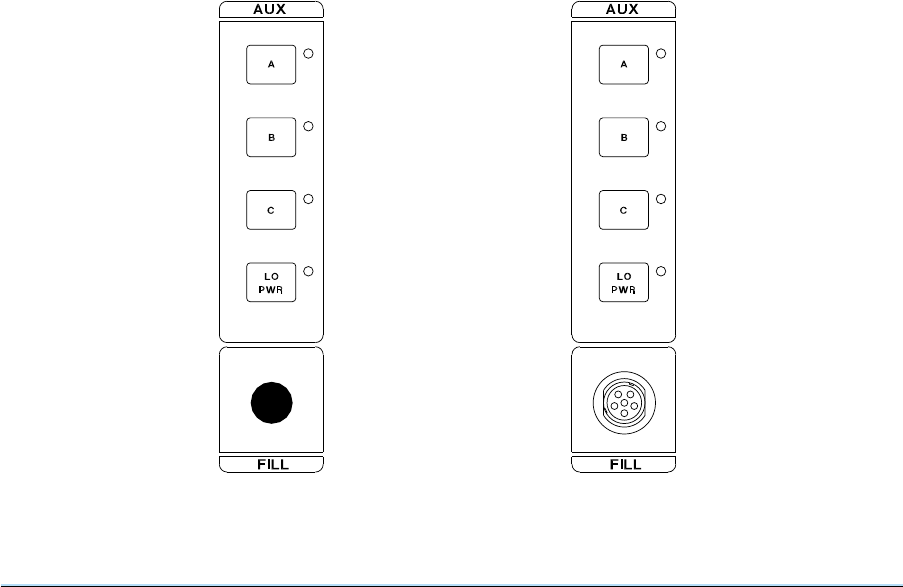
SUPPLY ON/OFF Switches
49 Two-position switches and associated indicators for the ac and the dc input supplies.
Auxiliary Controls
50 The auxiliary control pad (see Fig. 4-5) comprises four switches designated A, B, C, and LO PWR
(transmitters and transceivers) or D (receivers). On equipments with Option 05, a six-pin connector is
fitted. This is used to connect a fill gun or tape reader; these items are used to electronically read in the
Word-of-Day (WOD). The procedure for electronically reading in the WOD is given in the Have Quick
Supplement PAE Part No. 31B33060SUP and Quick Fox Supplement PAE Part No. 31-330600QF.
51 Switch A is used to enable or disable Crypto mode. Crypto mode can only be selected from Normal
mode. Crypto mode cannot be selected if an 8.33 kHz channel is being used. If it is selected, an error
message is displayed (see Table 4-5 on page 34). Selecting the AUX A key will enable the function and
cause the associated LED to illuminate. Pressing the following keys will de-select Crypto mode when
the radio is in Normal mode (non Anti-Jam mode):
LINK 11 AM/FM NB/WB AUX A
52 Crypto is available in Anti-Jam mode by selecting AUX A prior to entering Anti-Jam. To deselect
Crypto; exit the Anti-Jam mode, then de-select by pressing one of the above keys.
53 Switch B is used when electronically loading the WOD in Have Quick or Quick Fox applications.
Switch B, along with switches A and C, is also used as part of the key sequences required to view options
menus (see paragraph 81).
54 Switch LO PWR, when pressed and the indicator lit, sets the transmitter/transceiver into the low
power mode. If external power reduction is in operation the indicator flashes. For details of
internal/external power attenuator selection (see options on page 21). Switch D on a receiver is reserved
for future use.
3000DV2 Radios Section 4
Page 11
Fig. 4-5 Auxiliary Controls
Without Option 05
(Transceiver/
Transmitter control
pad shown)
With Option 05
(Transceiver/
Transmitter control
pad shown)

REAR PANEL CONNECTIONS
55 The equipments’ rear panel layout is shown in Fig. 4. Connector CN6 is reserved for future
development. The other connectors are described in the following paragraphs.
AC Supply
56 3-pin connector (with integral fuse) for the ac mains supply. The fuse rating must be selected
according to the local ac supply; details of fuse ratings are given in section 3 of this handbook.
DC Supply
57 3-pin connector (only 2 pins are used) for the connection of the incoming dc supply.
Remote Control Connector CN5
58 The remote control 9-way D-type connector is used to connect a PAE type 3000V2 remote control
unit (RCU). When an RCU is connected users must ensure that the identification code is correctly set
(see section 3). details of the connector’s pin-out is also given in section 3 of this handbook.
Facilities 2 Connector CN2
59 Facilities 2 is a 25-way D-type connector used to connect external control and monitoring signals.
The pin-out of this connector and a description of the external signals can be found in section 3 of this
handbook.
MPA/Filter Interface Connector CN3
60 The MPA/filter interface connector is a 37 way D type used to interface the equipment to external
filter/amplifiers (option 06).
Ext Clock CN4
61 The Ext Clock (external clock) connector is a 15-way D-type used to connect an external timing
source.
Section 4 3000DV2 Radios
Page 12

SETTING-UP AND OPERATING PROCEDURES
Note ...
When making key entries, do not pause more than 5 seconds between key strokes or new data will
be lost and the system will revert to default settings.
62 Before any setting-up procedures are carried out, users must ensure that the installation
instructions, as detailed in Section 3 of this handbook, have been successfully completed. Setting-up
the equipment requires the following procedures to be carried out:
❏Switching on the ac and dc supplies as applicable to the installation.
❏Frequency selection. This procedure is used to select an operating frequency without
programming the frequency and an appropriate channel number into the radio’s memory.
❏Programming channel and frequency information into the radio’s memory.
❏Channel recall. This procedure recalls a previously stored channel, setting the equipment to
operate on the frequency appropriate to that channel number.
❏Channel verification. This procedure allows an operator to check the frequency allocated to
any stored channel number.
❏Screen blanking (if this facility is required).
❏System reset and auto-calibrate (if necessary).
❏Guard receiver operation. This procedure is appropriate only to equipment which have the
guard receiver option fitted. The guard receiver provides constant monitoring of the
international distress frequency.
SWITCHING ON
63 The equipment can be operated from an ac or a dc supply. If both ac and dc supplies are
connected, the equipment will normally operate from the ac supply; if the ac supply fails, operation will
automatically transfer (without interruption) to the dc supply. When the ac supply is restored, the
equipment reverts to ac operation. Switching on is carried out as follows:
(a) At the equipment’s front panel, ensure the AC and DC SUPPLY switches are in the off
position (down).
(b) Apply ac, and/or, dc supplies to the equipment.
(c) If an ac supply is connected to the equipment, set the AC SUPPLY to the on position (up).
Check that the AC indicator is lit.
(d) If a dc supply is connected to the equipment, set the DC SUPPLY switch to the on position
(up). Check that the DC indicator is lit.
(e) Once power is established the radio then carries out a power-on self-test (see paragraph 111
on page 30).
3000DV2 Radios Section 4
Page 13
Users should note that there are different procedures for selecting frequencies and
channel information when using 25 kHz channel spacing, and 8.33 kHz channel spacing.
See FCC Warning page iv
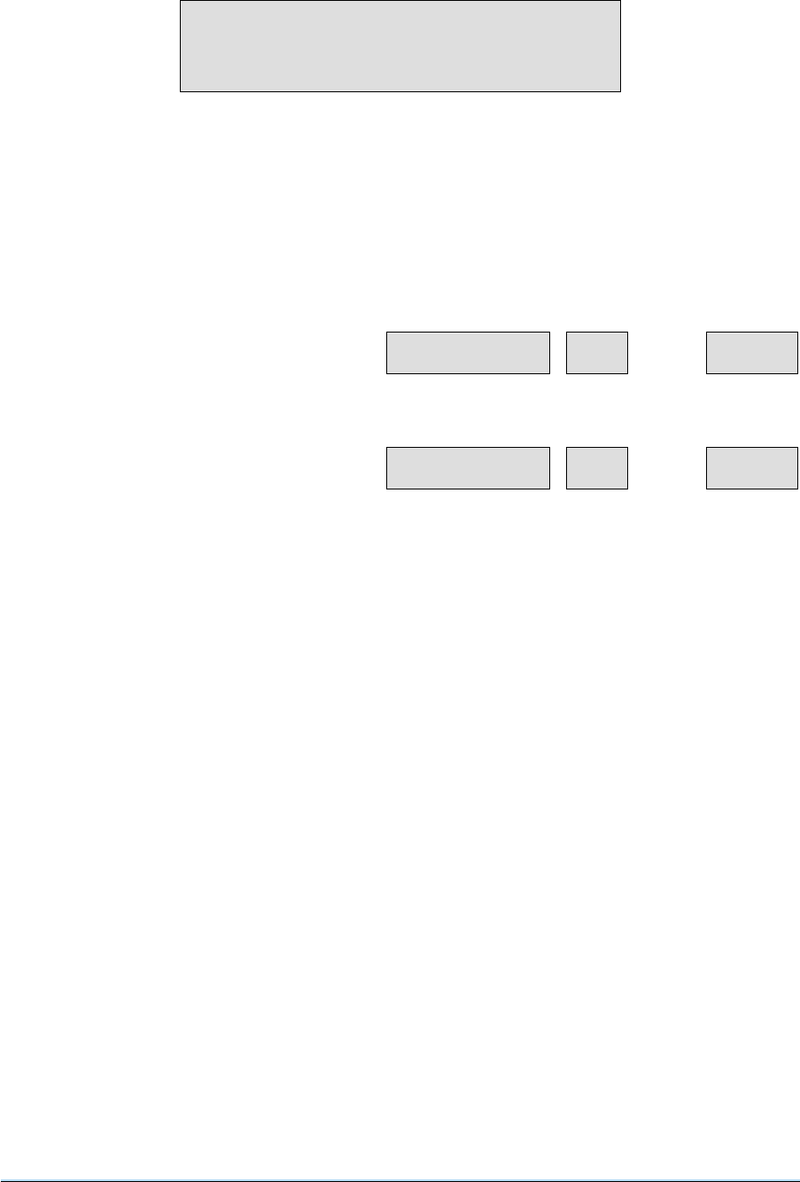
FREQUENCY SELECTION
64 The radio can be set to any operational frequency without allocating the frequency to a channel. To
set the frequency, proceed as follows:
(a) Using the numerical data keys, enter the required frequency, then press the FREQ key. The
equipment is now set to operate on the selected frequency. For example, to set 269.5 MHz:
(b) Using the numerical data keys,
enter the frequency 269.5 MHz.
The displays (in edit mode) show:
(c) Press the FREQ key. The displays
(in monitor mode) show:
(d) Select the required operational mode, for example, AM, NB. The radio is now set to operate
on 269.5 MHz, AM, narrow-band mode.
Section 4 3000DV2 Radios
Page 14
This procedure should be used when 25 kHz channel
spacing is required. If 8.33 kHz channel spacing is
being used, refer to paragraph 71 on page 17.
269.500.
FREQUENCY CHANNEL MONITOR
269.500
FREQUENCY CHANNEL MONITOR
See FCC Warning page iv
CHANNEL FREQUENCY SETTING
65 Up to 99 channels can be stored in the equipment’s memory. Each stored channel comprises an
associated frequency, and operational mode information. The following example details how to pre-set
channel 16 with a frequency of 251.025 MHz:
(a) At the radio’s front panel use the
numeric keys to enter the required
frequency: 251.025 MHz. The
displays show:
(b) Press the FREQ key. Displays (in
monitor mode) show:
(c) Set the AM/FM, narrow-band/wideband (NB/WB) and Link 11 mode select switches as
required for the frequency channel (for example, AM, NB, LINK 11 off).
(d) Using the numerical data keys,
enter the channel number
required, for example, 16.
Displays (in edit mode) show:
(e) Press the STORE key. Displays
(in monitor mode) show:
66 Channel 16 is now set to a frequency of 251.025 MHz operating in AM narrow-band mode. Other
channels up to a maximum of 99 can be set up as detailed in steps (a) to (e).
3000DV2 Radios Section 4
Page 15
This procedure should be used when 25 kHz channel
spacing is required. If 8.33 kHz channel spacing is
being used, refer to paragraph 71 on page 17.
251.025.
FREQUENCY CHANNEL MONITOR
251.025
FREQUENCY CHANNEL MONITOR
16 .
FREQUENCY CHANNEL MONITOR
251.025 16
FREQUENCY CHANNEL MONITOR
See FCC Warning page iv

CHANNEL RECALL
67 Channels may be recalled by using the numerical data keys to select the required channel number,
then pressing the RCL key. For example to recall channel 16, the sequence would be as follows:
(a) Using the numerical data keys
enter the channel number
required, e.g. 16. The displays (in
edit mode) show:
(b) Press the RCL key. The displays
(in monitor mode) show:
(c) The radio now operates on the displayed frequency. The AM or FM selection, and
narrow-band or wideband mode that was stored with the channel remains operational.
CHANNEL VERIFICATION
68 Any channel may be viewed for 5 seconds without changing the frequency, or affecting the
operation of the equipment. For example, to verify which frequency channel 37 is set to:
(a) Use the numerical data keys to
enter the channel number 37.
The displays will show:
(b) Press the second function key
(SHIFT s) and then press the
VIEW key. The displays will show
the frequency allocated to that
channel (see example) and the
channel number as follows:
(c) After five seconds, the displays will revert to the monitor mode and show the radio’s
operational frequency, which in this example is 251.025 MHz.
Section 4 3000DV2 Radios
Page 16
16 .
FREQUENCY CHANNEL MONITOR
251.025 16
FREQUENCY CHANNEL MONITOR
37 .
FREQUENCY CHANNEL MONITOR
260.100 37
FREQUENCY CHANNEL MONITOR

8.33 kHz CHANNEL OPERATION
69 The 3000DV2 VHF, or V/UHF, radios can operate between 118.000 MHz and 136.975 MHz using
8.33 kHz channel spacing. When setting a radio’s operating frequency to operate with 8.33 kHz channel
spacing, a special frequency designation should be entered from the front panel, not the actual
frequency.
70 Table 4-1 shows the special frequency pattern over the frequency range 118.0000 MHz to
118.1916 MHz. These channel designations have been defined by ICAO and are detailed in
ICAO Annex 10, Volume v, Chapter 4. The frequency designation pattern is repeated over the available
8.33 kHz frequency range (that is, up to 136.975 MHz). Examples for entering frequencies are given on
the next pages.
71 When 8.33 kHz channel spacing is used, the radio automatically selects AM and narrow-band
working. Other modes are not available with this channel spacing.
Table 4-1 8.33 kHz Channel Spacing - Special Frequency Designations
Actual Frequency
(MHz)
Frequency Designation
at 3000DV2 Radio (MHz)
118.0000
118.0083
118.0166
118.0250
118.0333
118.0416
118.0500
118.0583
118.0666
118.0750
118.0833
118.0916
118.1000
118.1083
118.1166
118.1250
118.1333
118.1416
118.1500
118.1583
118.1666
118.1750
118.1833
118.1916
118.005
118.010
118.015
118.030
118.035
118.040
118.055
118.060
118.065
118.080
118.085
118.090
118.105
118.110
118.115
118.130
118.135
118.140
118.155
118.160
118.165
118.180
118.185
118.190
3000DV2 Radios Section 4
Page 17
See FCC Warning page iv

Frequency Selection for 8.33 KHz Channel Spacing
72 The radio can be set to any operational frequency using 8.33 kHz channel spacing without
allocating the frequency to a channel. For example, to set 118.0083 MHz:
(a) Refer to Table 4- to determine the
frequency designation for the
actual frequency of 118.0083 MHz.
Using the numerical data keys,
enter the frequency designation
118.010 MHz. The displays (in edit
mode) show:
(b) Press the FREQ key. The displays
(in monitor mode) show:
(c) The radio is now set to operate on 118.0083 MHz, AM, narrow-band mode.
Section 4 3000DV2 Radios
Page 18
118.010.
FREQUENCY CHANNEL MONITOR
118.010
FREQUENCY CHANNEL MONITOR
See FCC Warning page iv
Channel Frequency Setting for 8.33 KHz Channel Spacing
73 Up to 99 channels can be stored in the equipment’s memory. Each stored channel comprises an
associated frequency, and operational mode information. The frequencies can operate with 25 kHz
channel spacing, 8.33 kHz channel spacing, or a mixture of both. The following example details how to
pre-set channel 37 with a frequency of 126.4583 MHz:
(a) Refer to Table 4-1 to determine the
frequency designation for the
actual frequency of 126.4583
MHz. Using the numerical data
keys, enter the frequency
designation 126.4600 MHz. The
displays (in edit mode) show:
(b) Press the FREQ key. The displays
(in monitor mode) show:
(c) Using the numerical data keys,
enter the channel number
required, for example, 37.
Displays (in edit mode) show:
(d) Press the STORE key. Displays
(in monitor mode) show:
74 Channel 37 is now set to a frequency of 126.4583 MHz operating in AM narrow-band mode (AM and
narrow-band working are automatically selected when an 8.33 kHz channel spaced frequency is
chosen). Other channels up to a maximum of 99 can be set up as detailed in steps (a) to (d) above, or if
25 kHz channels are required see paragraph 65.
3000DV2 Radios Section 4
Page 19
126.460.
FREQUENCY CHANNEL MONITOR
126.460
FREQUENCY CHANNEL MONITOR
37 .
FREQUENCY CHANNEL MONITOR
126.460 37
FREQUENCY CHANNEL MONITOR
See FCC Warning page iv

SYSTEM RESET
75 The system reset command resets the radio resulting in all options, channel and synthesiser
calibration information being lost. Before further use, and following this command, an auto-calibrate
procedure must be carried out (see paragraph 77).
76 The system reset key sequence 91, (SHIFT s), RESET resets the radio and returns it to a known
state. After a system reset (plus auto-calibrate) frequency and channel settings must be re-entered.
AUTO-CALIBRATE
77 The auto-calibrate routine recalibrates the synthesiser lock times, and needs to be initiated after a
system reset. (A system reset clears the equipment of all stored data). To initiate the auto-calibrate
routine, use the following procedure:
(a) Ensure the step auto-calibrate size is 25 kHz (0.025 MHz). The key sequence is
0.0 2 5, (SHIFT s), FREQ
(b) Initiate auto-calibrate. The key sequence for this is: 91, AUX C
(c) Set the radio to the lowest available frequency, 100 MHz (VHF or VHF/UHF radio) or
225 MHz (UHF only radio).
(d) The equipment will then go through the calibration routine which takes approximately
10 minutes. During this time, the frequency display shows Calib, the channel display shows
ON and the monitor display increments from 1 to 100 to give a progress indication.
(e) When the equipment has stepped through all UHF and VHF channel frequencies (all
channels have been calibrated when the frequency display returns to the original frequency
display), stop the routine by switching off the radio. Auto-calibration can be stopped by
entering 91, AUX C.
(f) Re-enter any required channel frequencies. The radio is now ready for operational use.
GUARD RECEIVER OPERATION
78 The GUARD mode function is only available when the guard receiver option is fitted. Selection of
the guard receiver is achieved by selecting the guard ON key to the on position (shown by the adjacent
indicator being lit).
79 The guard receiver will continuously monitor the international VHF distress frequency of 121.5 MHz
when the main receiver is set to a VHF frequency or the UHF distress frequency of 243 MHz when the
main receiver is set to a UHF frequency. When a signal is detected on the guard frequency the indicator
adjacent to the guard MUTE key will light and the audio will be heard in the loudspeaker, headset, or
through the guard receiver’s audio output that is available on the facilities 2 connector.
80 When a distress broadcast is received through the guard receiver, the operator can select the
distress frequency as the equipment’s operating frequency by using the channel recall procedure, or the
frequency selection procedure.
Section 4 3000DV2 Radios
Page 20

OPTIONS, SOFTWARE VERSIONS, AND RADIO TYPE MENUS
81 There are three menus (options, software versions and radio type) available via the front panel.
Options (in the options menu) can be viewed and changed, the other two menus are read only. The key
sequences needed to view each particular type are shown in Table 4-2.
Table 4-2 Options, Software Versions, and Radio Type Menus
Key Sequence Monitor Display Selected Menu
91, Shift s, Aux B
91, Shift s, Aux C
91, Shift s, Aux A
oPt
SoFt
tyPE
Options menu
Software Versions menu
Radio Type menu
82 Each menu is described in the following paragraphs.
Options
83 To activate the options menu, enter the key sequence shown in Table 4-2.
84 When in view mode, as indicated by the BIT display changing to the appropriate display stream, the
user can scroll up (Shift s) and down (Shift t) through the available options and their current state. If
the option is selectable then the numeral 1 key can be used to enable the option and the numeral 0 key
can be used to disable the option. Selected options are activated by pressing the STORE key, and then
switching the set off and back on.
85 The options that can be activated from the menu are:
❏Option 01, Guard Receiver (can be activated only when a guard receiver module is fitted in the
radio).
❏Option 04, Fill Gun Port (can be activated only when a fill gun connector is fitted to the radio’s
front panel).
❏Option 06, Interface for an external power amplifier or external auto-tune filter.
❏Option 07, Have Quick operation (can be activated only when a Have Quick module is fitted in
the radio).
❏Option 08, VHF frequency extension that increases the VHF band from 100 to 163 MHz.
❏Option 10, Maritime band working. When Option 10 is selected the VHF frequency band is
extended to 163 MHz only for designated marine channels. If the radio is required to operate
on maritime channels, and non-maritime channels above 155.975 MHz, both Option 08
and Option 10 must be selected.
❏Option 12, Quick Fox working. This should only be selected on radios modified for, and fitted
with a Quick Fox module. Note that the radio’s front panel has modified key names.
❏AttEnU. Must be activated if an external attenuator is being used with the radio.
3000DV2 Radios Section 4
Page 21
Note ...
If option 05 is selected without either option 07 or 12 selected, the following error message will be
displayed during a POST check:
86 The following sequence shows how to activate marine mode. in the example shown the key
sequence is continued after enabling option 10, to show all available selections, but can be terminated at
any time by pressing the STORE key, and then switching the set off and back on.
87 Pressing the STORE key stores all selections and terminates the function. Pressing the CE key
terminates the function without saving the selections. After selecting which options are to be
activated, power should be removed from the radio, and then reapplied.
Section 4 3000DV2 Radios
Page 22
325.000. 21
oPt 01 00 oPt
oPt 05 00 oPt
oPt 06 00 oPt
oPt 07 00 oPt
oPt 08 00 oPt
oPt 10 00 oPt
oPt 10 01 oPt
oPt 12 00 oPt
AttEnU 00 oPt
325.000. 21
FREQUENCY CHANNEL MONITOR
Before key sequence
91, (SHIFT s), Aux B
(SHIFT t)
(SHIFT t)
(SHIFT t)
(SHIFT t)
(SHIFT t)
1
(SHIFT t)
(SHIFT t)
Press STORE
noFLgn -- POSt
FREQUENCY CHANNEL MONITOR
Viewing Software Versions
88 Three items of software are installed in the radio: Synthesiser (sy), Front Panel (FP), and Remote
Control (rC). The software numbers and versions can be viewed using the following key sequences.
3000DV2 Radios Section 4
Page 23
Press 91 (SHIFT s), Aux C
Before key sequence (example)
Press (SHIFT t)
Press (SHIFT t)
Press CE key to end viewing
263-00 sy Soft
325.000. 21
FREQUENCY CHANNEL MONITOR
264-00 FP Soft
265-00 rC Soft
325.000. 21

Radio Type Menu
89 The following key sequences show how to interrogate the radio to display the radio type. This
procedure is an engineering facility and is unlikely to be of value to an operator. If an unknown display is
shown, this indicates that the switches fitted to the BITE module are incorrectly set. Refer to the
Technical Handbook.
SCREEN BLANKING
90 The operator may ‘blank’ the frequency and channel screen display by selecting the key sequence
91, (SHIFT s), 5.
91 The following functions will be available when the screen is blanked:
❏PTT
❏Monitor functions.
92 To restore the frequency and channel displays, select the key sequence 91, (SHIFT s), 5.
Section 4 3000DV2 Radios
Page 24
Press 91 (SHIFT s), Aux A
Before key sequence (example)
if the radio type is unknown
Press CE key to end viewing
3140 ttyPE
325.000. 21
FREQUENCY CHANNEL MONITOR
---- -- tyPE
325.000. 21

TRANSMIT OPERATION (FOR TRANSMITTERS AND TRANSCEIVERS ONLY)
93 On the synthesiser front panel (see Fig. 4-3), select the required operational frequency either by
recalling a pre-set channel, or by using the numeric keypad (as detailed in previous paragraphs).
94 Transmission can now take place by operating the PTT switch and speaking into the microphone.
95 A sidetone of the transmitted audio is available from the MIC/HEADSET or MIC socket if the
speaker is switched off.
96 A data (wideband) input is also available at the rear panel FACILITIES connector. If using this
function ensure that the narrow-band/wideband (NB/WB) mode has been set for wideband (WB).
RECEIVE OPERATION (FOR RECEIVERS AND TRANSCEIVERS ONLY)
97 On the synthesiser front panel (see Fig. 4-3), select the required operational frequency either by
recalling a pre-set channel or by using the numeric keypad (as detailed in previous paragraphs).
98 Verify that the displayed frequency is correct. Reception will now take place with the audio being
available at the MIC/HEADSET socket and the internal loudspeaker (when set to the on position). All
audio outputs can be controlled using the VOL control.
99 A data (wideband) output is also available at the rear panel FACILITIES 2 connector. The level of
this output is pre-set.
3000DV2 Radios Section 4
Page 25

MARITIME BAND - ADDITIONAL OPERATING INFORMATION
GENERAL
100 Radios incorporating the maritime band option (Option 10) are user selectable between the
following operational modes:
❏Normal (non-maritime band operation)
❏Ship (maritime band operation)
❏Shore (maritime band operation).
NORMAL MODE
101 The normal (or non-maritime mode) will perform identically to a radio without maritime capability.
The only exception is an additional key sequence that is required to switch into one or other of the
maritime modes (see paragraph 109).
SHIP/SHORE MODES
102 In maritime mode, the channels 1 to 28, 60 to 74 and 77 to 88 (see Table 4-4) are overlaid with
international maritime VHF frequencies. These particular channels cannot be altered by the operator
although the remaining channels still have this capability.
103 As the actual frequency of transmission and reception are pre-set for maritime channels, the 6-digit
display will either indicate ‘SH IP.’ or ShorE.’. The display will also include one of the following suffix
characters:
‘I’ - denotes International selection (i.e. SH IP.I or ShorE.I)
‘A’ - denotes American selection (i.e. SH IP.A or ShorE. A)
104 The format in use may be toggled by a key sequence (see paragraph 109).
Ship/Shore View Modes
105 In the ship/shore view modes the current operating frequency is displayed at all times. During
reception, the receive frequency is displayed. the display will then indicate the transmit frequency during
subsequent transmissions (this allows test engineers to check that the radios are transmitting and
receiving on the correct frequency).
Section 4 3000DV2 Radios
Page 26

Channel Change
106 Changing maritime channels follows the same format as with normal channel changes. As digits
are entered, they are displayed on the frequency display. Once a valid selection has been made, the
new channel is selected. If this is within the maritime range, the display will return to maritime mode, i.e.
displaying ‘SH IP.A’ (SH IP.I) or ‘ShorE.A’ (ShorE.I) unless in view mode.
Frequency Change
107 Maritime frequencies cannot be changed as they are internationally set. If a frequency is entered,
the frequency display will show ‘Error’ and the channel display will show the error number 10.
Note ...
The channels not covered by the maritime standards may be re-programmed as normal. These
channels are duplicates of those in non-maritime mode and as such, any changes made will remain
when maritime mode is de-selected.
External RF Filter
108 The external RF filters normally used with 3000DV2 series equipment require a few seconds to
retune to a new frequency and cannot be used for filtering both transmission and reception signals on a
Two Frequency Simplex channel. If a filter is fitted when one of these channels is recalled, an error
message will be displayed (see Table 4-5).
3000DV2 Radios Section 4
Page 27

KEY SEQUENCES
109 The following describes the additional key sequences required to access the maritime functions:
Table 4-3 Maritime Function Key Sequences
Required Function Key Sequence Display
Change from any operating mode to
Normal mode 0, SHIFTt, FREQ Transceiver frequency (for example,
156.125)
Change from any operating mode to
Ship mode 1, SHIFTt, FREQ SH IP.A or SH IP.I
Change from any operating mode to
Shore mode 2, SHIFTt, FREQ ShorE.A or ShorE.I
Change from Ship mode to Ship
View mode SHIFTs, VIEW Transmitter, or Receiver frequency
(for example 156.125)
Change from Ship View mode to
Ship mode SHIFTs, VIEW SH IP.A or SH IP.I
Change from Shore mode to Shore
View mode SHIFTs, VIEW Transmitter, or Receiver frequency
(for example 156.125)
Change from Shore View mode to
Shore mode SHIFTs, VIEW ShorE.A or ShorE.I
Change from International format to
American format SHIFTt, FMT SH IP.A or ShorE.A
Change from American format to
International format SHIFTt, FMT SH IP.I or ShorE.I
Section 4 3000DV2 Radios
Page 28

Table 4-4 Maritime Frequencies
Channel
Number
Ship to Tx
Frequency
Shore Tx
Frequency
Channel
Number
Ship to Tx
Frequency
Shore Tx
Frequency
60 156.025 160.625
01* 156.050 160.650 61 156.075 160.675
02 156.100 160.700 62 156.125 160.725
03 156.150 160.750 63* 156.175 160.775
04 156.200 160.800 64 156.225 160.825
05* 156.250 160.850 65* 156.275 160.875
06 156.300 156.300 66* 156.325 160.925
07* 156.350 160.950 67 156.375 156.375
08 156.400 156.400 68 156.425 156.425
09 156.450 156.450 69 156.475 156.475
10 156.500 156.500 70 156.525 156.525
11 156.550 156.550 71 156.575 156.575
12 156.600 156.600 72 156.625 156.625
13 156.650 156.650 73 156.675 156.675
14 156.700 156.700 74 156.725 156.725
15 156.750 156.750 75 see comment 1 see comment 1
16 156.800 156.800 76 see comment 2 see comment 2
17 156.850 156.850 77 156.875 156.875
18* 156.900 161.500 78* 156.925 161.525
19* 156.950 161.550 79* 156.975 161.575
20 157.000 161.600 80* 157.025 161.625
21* 157.050 161.650 81* 157.075 161.675
22* 157.100 161.700 82* 157.125 161.725
23 157.150 161.750 83* 157.175 161.775
24 157.200 161.800 84 157.225 161.825
25 157.250 161.850 85 157.275 161.875
26 157.300 161.900 86 157.325 161.925
27 157.350 161.950 87 157.375 161.975
28 157.400 162.000 88* 157.425 162.025
* Denotes that for American format, use Ship Tx Frequency for both ship and shore, i.e. Simplex.
Comment 1: Guard-band 156.7625 to 156.7825 MHz; Marine channel not used.
Comment 2: Guard-band 156.8125 to 156.8375 MHz; Marine channel not used.
3000DV2 Radios Section 4
Page 29
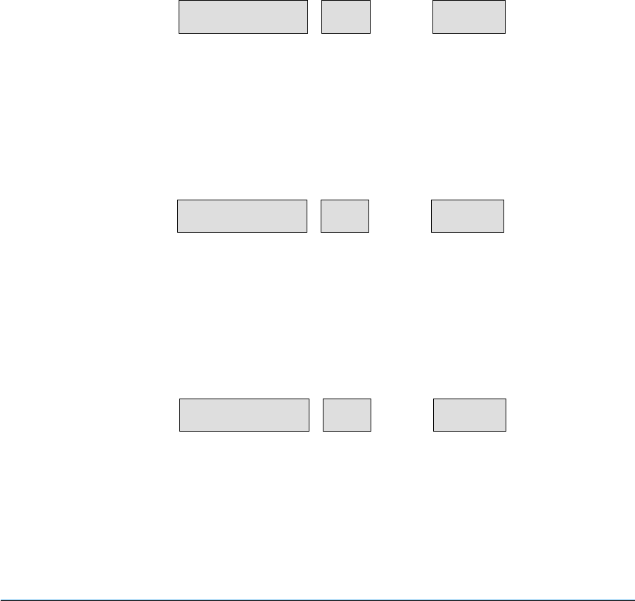
BUILT-IN TEST (BIT) OPERATION
110 The BIT functions monitor key radio parameters and provides an indication if an equipment
malfunction occurs. The BIT functions in three different ways:
❏Power-On Self-Test (POST)
❏Continuously monitored functions
❏Interruptive self-test routines.
POWER-ON SELF-TEST
111 A power-on self-test (POST) is performed to check the basic functionality of the radio.
112 If no problems are revealed PASS is shown in the monitor display; see following example:
113 If a problem exists with the synthesiser, the frequency window shows the following message (this
message indicates the set is inoperative and cannot be used):
114 Any other post-initialisation problems are indicated by having the BIT display window show ‘POSt’
as shown in the following example:
Section 4 3000DV2 Radios
Page 30
225.000 01 PASS
FREQUENCY CHANNEL MONITOR
nO Syn 3POSt
FREQUENCY CHANNEL MONITOR
305.000 01 POSt
FREQUENCY CHANNEL MONITOR

115 On error the MEM key can be used to view each problem in turn, so that each POST problem can be
noted. For example, if the internal Have Quick module (anti-jam) option is enabled and the Have Quick
module has failed, the MEM key should be pressed a number of times and the following display will be
shown:
116 Pressing the MEM key a number of times will cause each POST problem in turn to be shown,
returning to the original display when all POST codes have been shown. The post-initialisation test can
only be cleared by switching the set off, fixing the problem concerned and switching the set back on
again. Analysing faults is outside the scope of this handbook. Reference should be made to the
appropriate technical handbook for further information.
CONTINUOUSLY MONITORED FUNCTIONS
117 The BIT automatically performs test routines that monitor the equipment’s test point voltages at
least once every two seconds. If a test point voltage is found to be outside the pre-set limit, the module
and test point numbers are stored in the fault memory. The error message ‘bit’ will be shown on the
monitor display. If the fault is only temporary, the bit error message will disappear.
118 If the fault is caused by an external influence and the set is still operating correctly at reduced power,
one of the following messages will be displayed:
❏If a high temperature within the equipment is sensed, the error message °C will be shown on
the monitor display.
❏If the fault is caused by a high VSWR at the VHF antenna connection, ANT 1 will be shown on
the monitor display.
❏If the fault is caused by a high VSWR at the UHF antenna connection, ANT 2 will be shown on
the monitor display.
❏If the fault is caused by a low supply voltage AC or DC (as selected), PS will be shown in the
monitor display.
❏If the fault is with an external power amplifier, 3640, Ebit will be shown in the monitor display.
Under this condition the set will be operating correctly at full power, however the 3640 will be in
bypass condition (non-amplifying). When the 3640 fault is cleared, the following key sequence
must be entered at the radio to clear the bypass condition and restore normal working:
SHIFTs, RESET
3000DV2 Radios Section 4
Page 31
nO AJ 7POSt
FREQUENCY CHANNEL MONITOR

INTERRUPTIVE SELF-TEST ROUTINE
119 This test is initiated by pressing the TEST key. During the self-test routine, normal operation of the
equipment is suspended, and the TEST indicator is on.
120 At the start of the test, the fault memory is cleared and the MEM indicator is turned off. If a fault is
found, the module and test point number is stored in the fault memory, and the MEM indicator turned on.
The test routine then proceeds to the next module.
121 On completion, one of the following status messages is shown on the MONITOR display:
❏PASS - indicating system is fully operational.
❏bit - indicating one or more out of limit conditions exist.
❏tCAr - indicating the interruptive test has been aborted. The transmitter’s carrier output power
is below specification, i.e. less than 4 watts (not applicable to receivers).
❏tAUd - indicating the interruptive test has been aborted. The transmitter’s depth of modulation
is below specification, i.e., less than 50% (not applicable to receivers).
❏rSEn - indicating the interruptive test has been aborted. The receiver’s sensitivity is below
specification (not applicable to transmitters).
❏rAUd - indicating the interruptive test has been aborted. The receiver’s audio is below
specification (not applicable to transmitters).
❏ANT 1 - indicating high VSWR present at the VHF antenna connection.
❏ANT 2 - indicating high VSWR present at the UHF antenna connection.
❏°C - indicating equipment above normal operating temperature.
❏PS - indicating low supply voltage AC or DC as selected.
❏EbIt - indicating an external error has occurred. When an external power amplifier type 3640 is
connected to the radio and this message is received, the 3640 is switched to the bypass
condition (non-amplifying). When the fault is cleared in the 3640, the following key sequence
must be entered at the radio to clear the 3640 bypass condition and restore normal working of
the 3640:
SHIFT s, RESET
Note ...
During antenna testing it is not possible for the equipment to indicate a fault on both VHF and UHF
antenna systems simultaneously. Should this situation occur, the first detected fault will be
displayed on the monitor. It is therefore advisable to check both antenna systems independently in
the event of a failure indication.
Section 4 3000DV2 Radios
Page 32

FAULT MEMORY
122 The fault memory contains one location for each module. The contents of the memory can be
viewed by pressing the memory (MEM) key. Successive MEM key presses display any other stored
faults in rotation.
123 Internal faults are displayed on the monitor display as module number and test point number.
External faults are displayed as ANT 1, ANT 2, °C, PS, and EbIt indicating VHF transmitter VSWR, UHF
transmitter VSWR, temperature, supply voltage, and an external equipment fault respectively.
124 The fault memory is cleared by pressing SHIFT s, RESET.
3000DV2 Radios Section 4
Page 33

Table 4-5 Error Message Codes
Code Meaning Action
01 *Check sum error Indicates marginal line conditions. Clears on next
correct polling sequence or pressing CE key.
02 Not used
03 Not 25 or 8.33 kHz channel Press the CE key and enter the correct frequency
related to relevant kHz channel spacing.
04
*Attempted to change
frequency at RCU with
LOCK selected
Indicates that the LOCK function is selected.
Press the CE key to regain Edit Mode. Select the
UNLOCK function at the RCU unit to allow the
locked out function to be set - if permitted.
05-09 Not used
10-14 Not used
15 FM mode not available at this
frequency
Press CE key, select another frequency if FM
required.
16 *Serial Data Failure
This error code is displayed only at the 3000V2
Remote Control Unit (RCU). This code indicates a
communication link failure between the
transmitter or receiver and the 3000V2 RCU. The
fault can be in the transmitter or receiver, data link,
or the 3300 Data Unit. The error code clears when
the CE key is pressed, but is displayed again after
approximately ten seconds if the fault has not been
cleared.
17-24 Not used
25 Attempt to change frequency
of maritime channel Exit maritime mode if change required
26-36 Not used
37 RF filter incompatible with
transmission mode
Remove RF filter or select single frequency
transmission
38 Out of range Press CE key and re-enter data
39 *Same IDs
One or more radios in the system have the same
IDs. Reconfigure radio IDs and restart.
Applicable to split and non-split sites.
Section 4 3000DV2 Radios
Page 34

Table 4-5 Error Message Codes (continued)
Code Meaning Action
40 *Too many radios in system Split-site operation - two radios only.
Non split-site operation - 15 radios.
41
*Transceiver split. One or
more radios in split-site
configuration is a transceiver
Reconfigure radios and restart.
42
*Two transmitter split. Both
radios in split-site are
transmitters
Reconfigure radios and restart system.
43
*Two receiver split. Both
radios in split-site are
receivers
Reconfigure radios and restart system.
44
*VHF/UHF split. Radios in
split-site have different
frequency bands
Reconfigure radios and restart system.
45
*In split-site operation a radio
has not responded to the
3000V2 RCU
Reconfigure radio and restart system.
46 *Radio Busy
Radio is unable to perform required function. For
example radio commanded to exit Anti-Jam when
not in Anti-Jam mode. Press CE key to
acknowledge fault and continue operation.
47 *Havequick function not
available
Havequick function not available at this radio.
Press CE key and select another operation.
48 WB mode not available at this
frequency
Press CE key, select another frequency if WB
required.
49 Link 11 mode not available at
this frequency
Press CE key, select another frequency if Link 11
required.
50 Crypto mode not available at
this frequency
Press CE key, select another frequency if crypto
mode required.
Note...
*means error message code only displayed at an associated remote control/monitoring equipment
(such as a PAE 3000V2 remote control unit).
3000DV2 Radios Section 4
Page 35

USER MAINTENANCE
FILTER CLEANING
125 The air filters, fitted to the equipment’s rear panel, should be cleaned every six months (or more
regularly in high dust conditions). The filter is cleaned as follows:
(a) Ensure that the equipment has been isolated from the input ac and dc supplies.
(b) At the rear of the unit, locate and remove the two screws that secure the fan filter housing to
the rear panel (see Fig. 4).
(c) Remove the filter housing, fan EMC screen and filters. Clean the filters either by using a low
pressure air supply or washing in warm water and leaving to dry. If necessary replace with a
new filter (PAE Part No. 51-00507867).
(d) Refit the filters, fan EMC screen and filter housing.
LAMP TEST
126 The lamp test allows all the front panel LEDs and lamps to be illuminated simultaneously allowing
the operator to check for unserviceable lamps/LEDs. To carry out the test, press the SHIFT(s) followed
by the 0 (zero) key. The test is cancelled by pressing the CE key. Note that this test does not check the
AC and DC supply lamps.
FREQUENCY ACCURACY CHECK
127 The ac accuracy of the transceiver’s and transmitters's frequency can be checked if a suitable
frequency counter and 30 dB attenuator are available. It is recommended the frequency check be
completed every six months as follows:
(a) Connect a digital frequency counter, through a 30 dB attenuator, to the VHF (or UHF)
antenna connector.
(b) At the front panel, select a frequency of 155 MHz (VHF transmitter) or 399 MHz (UHF
transmitter and VHF/UHF transceiver) and key the transmitter. Check that the frequency
indicated on the frequency counter is between 154.999 and 155.001 MHz (VHF) or 398.999
and 399.001 MHz (UHF).
(c) If the specification in step (b) is not met, reference should be made to PAE.
Section 4 3000DV2 Radios
Page 36

Spares
Contents
Paragraph
1 Introduction
3 Parts list
INTRODUCTION
1 This section details the PAE part numbers for items referred to in this handbook. The radio’s full
parts listing is contained in the associated technical handbook.
2 When ordering parts from PAE, the item, full description, and PAE part number should be quoted.
3000DV2 Radios Section 5
Page 1

PARTS LIST
3 PAE part numbers for items referred to in this handbook.
Item Description Part number
- 3040V2, UHF transceiver B3040V2
- 3070V2, VHF transceiver B3070V2
- 3060V2, VHF/UHF transceiver B3060V2
- 3140V2, UHF transmitter B3140V2
- 3170V2 VHF transmitter B3170V2
- 3160V2, VHF/UHF transmitter B3160V2
- 3240V2, UHF receiver B3240V2
- 3270V2, VHF receiver B3270V2
- 3260V2, VHF/UHF receiver B3260V2
- Series 3000DV2 Radios User Guide 31-33000DTR
- Series 3000DV2 Transceiver Technical Handbook 31-13000DTR
- Series 3000DV2 Transmitter Technical Handbook 31-13000DTX
- Series 3000DV2 Receiver Technical Handbook 31-13000DRX
FS1 Fuse (size 0, 1.25 inch) 20 A - F20A 32 V BS 29-01450201
FS2 Fuse (20 mm)4A-F4A250VIEC 29-01120101
FS3 Fuse (20 mm)8A-T8A250VIEC
(when used with 110/120 V ac input supply) 29-01210102
FS3 Fuse (20 mm)4A-T4A250VIEC
for 220/240 V ac input supply 29-01120102
Air filter Rear panel replacement air filter 51-00507867
Free-standing accessory kit 70-3060TR1
Anti-vibration mount accessory kit 70-3060TR2
ac connector Free-connector for mating with the equipment’s AC connector 20-02030102
dc connector Free-connector for mating with the equipment’s DC connector 20-01030106
Ant connector N-type plug (for RG213 cable) that mates with radio’s ANT connector 19-01030301
Antenna cable Coaxial cable type RG213 (see note) 10-05120600
Ant connector N-type plug (for RG174 cable) that mates with radio’s ANT connector 19-01030306
Antenna cable Coaxial cable type RG174 (see note) 10-05120200
Free-standing accessory kit 70-3060
Note ...
Two types of antenna cable (and appropriate N-type connectors) are detailed. RG213 is the
normally recommended cable. However, RG174, which has better loss and power handling
characteristics can be used.
Section 5 3000DV2 Radios
Page 2

Figures
The following A3 size figures are bound in this section
Figure
1 3000DV2 transceiver front panel······················GA9553
2 3000DV2 transmitter front panel ······················GA8635
3 3000DV2 receiver front panel ·······················GA8636
4 3000DV2 radio panel view ·························GA8535
5 Fitting telescopic slides···························GA2983
6 Free standing kit assembly·························GA7869
7 Anti-vibration mount assembly ·······················GA8528
8 Assembly of N-type plugs ·························GA7883/4
9 3000DV2 overall dimensions························GA7868
3000DV2 Radios Section 6
Page 1
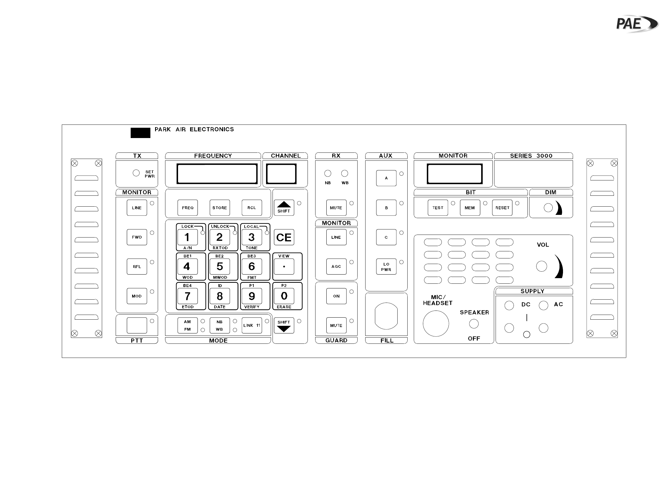
3000DV2 Transceiver Front Panel
Fig. 1
(GA9553 Iss. 1)
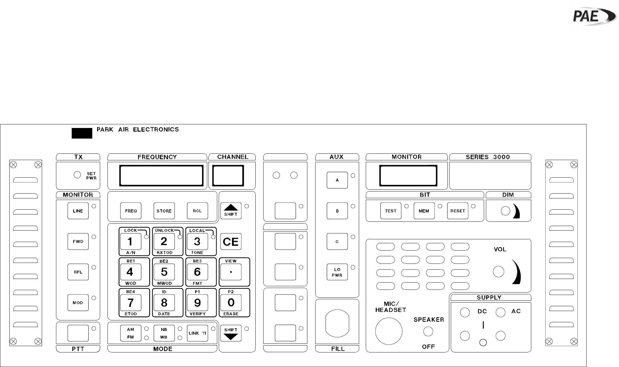
3000DV2 Transmitter Front Panel
Fig. 2
(GA8635 Iss. 1)
3000DV2 Receiver Front Panel
Fig. 3
(GA8636 Iss. 2)
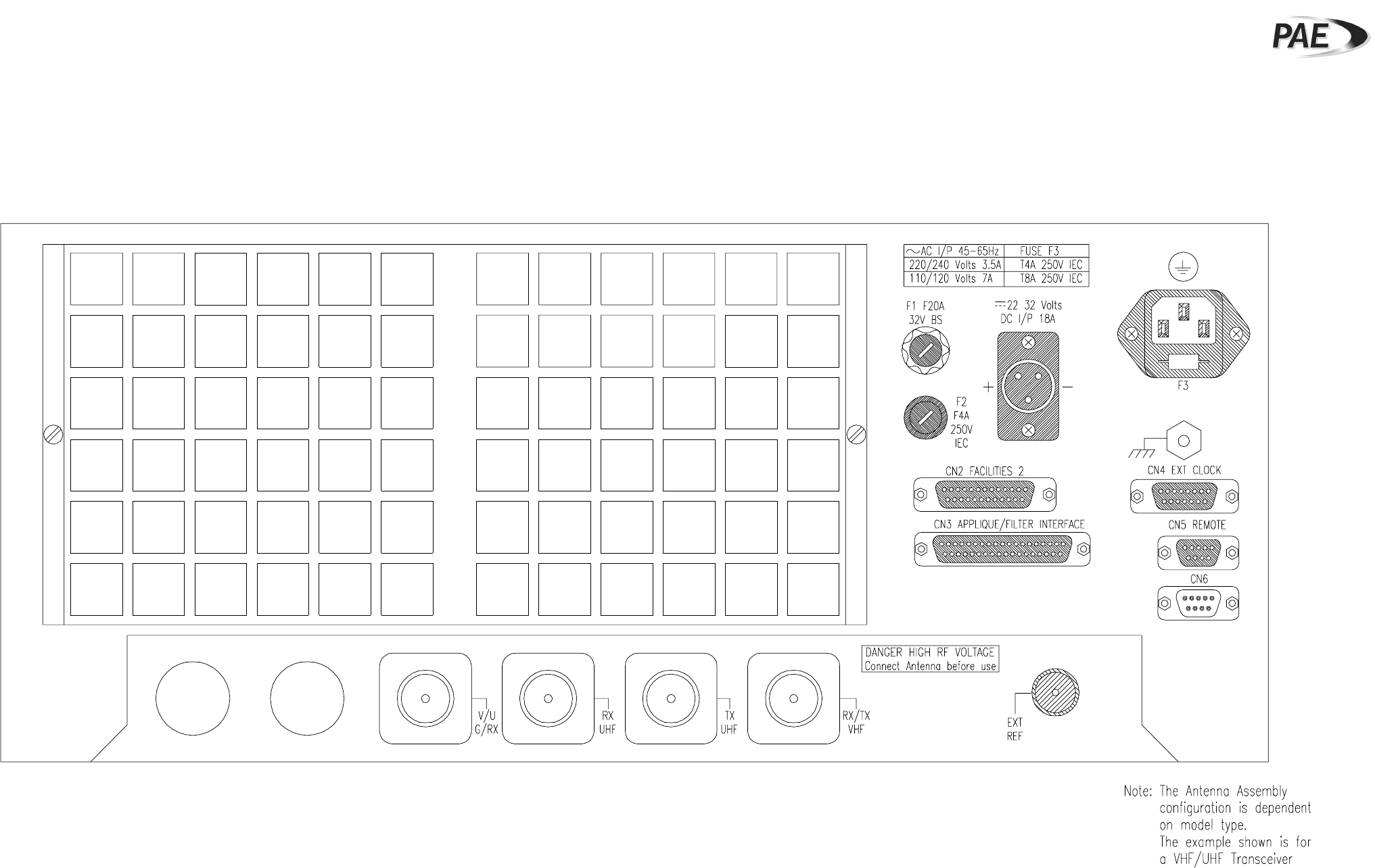
3000DV2 Rear Panel View
Fig. 4
(GA8535 Iss. 1)
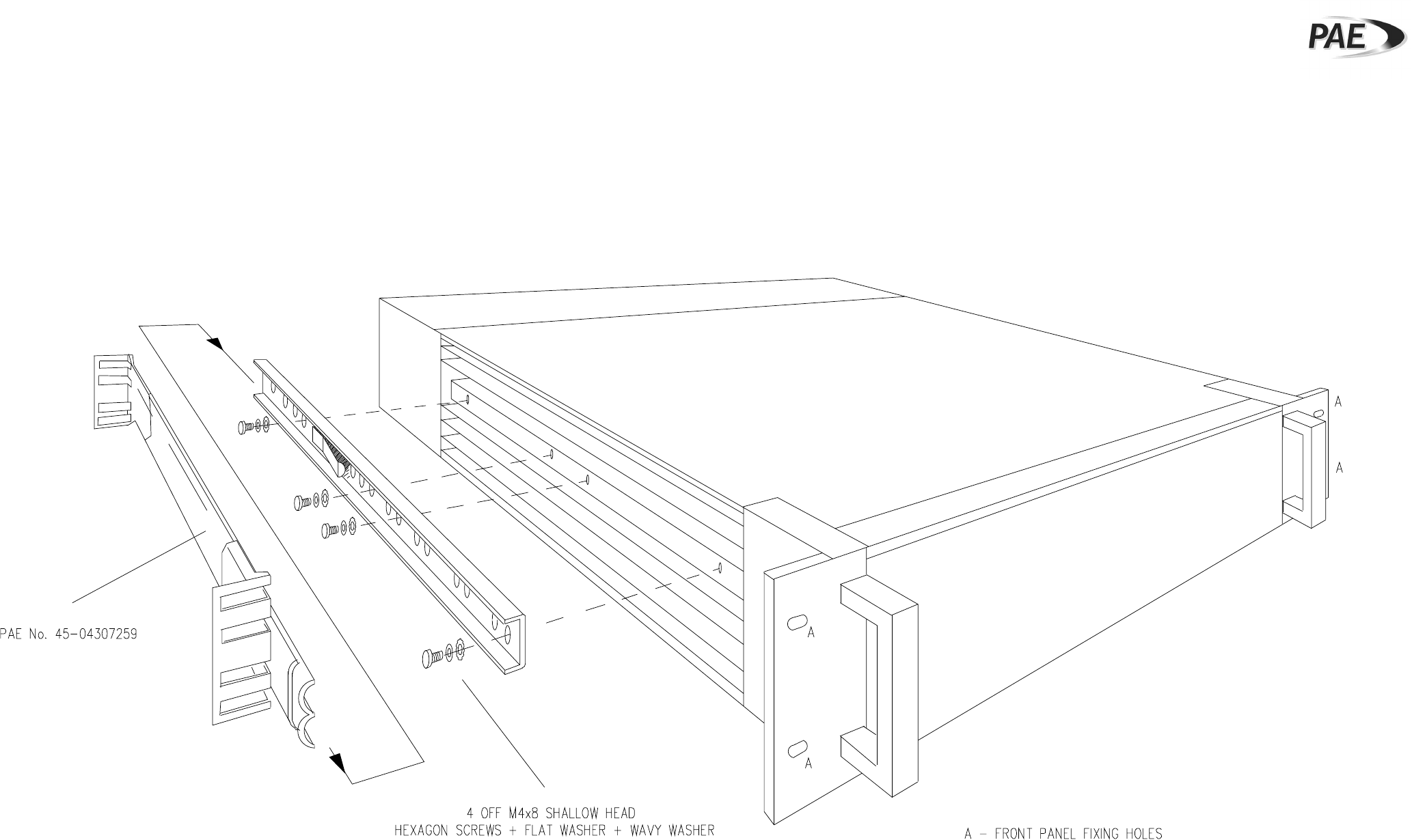
Fitting Telescopic Slides
Fig. 5
(GA2983 Iss. 3)
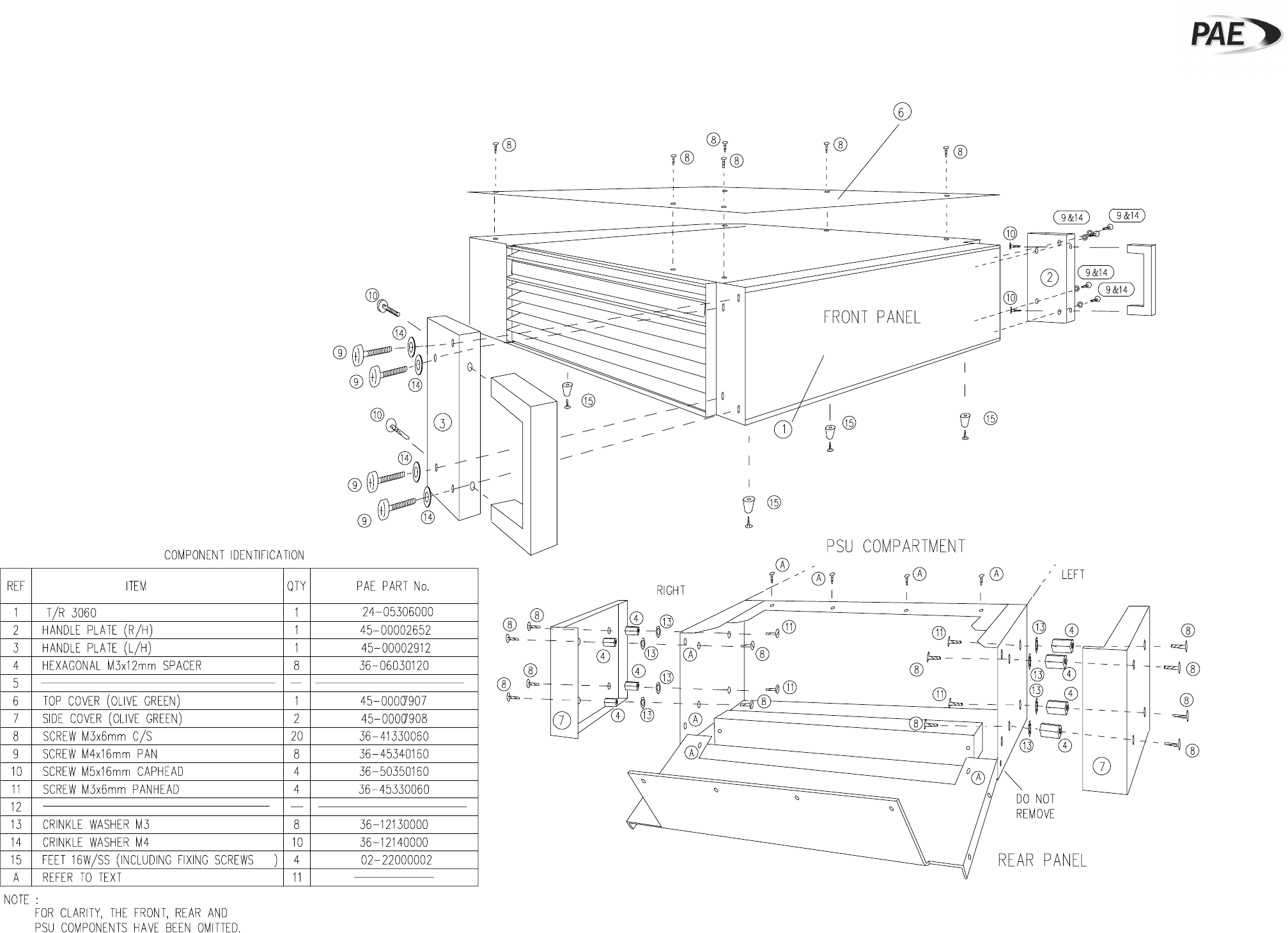
Free-Standing Kit Assembly
Fig. 6
(GA7869 Iss. 2)
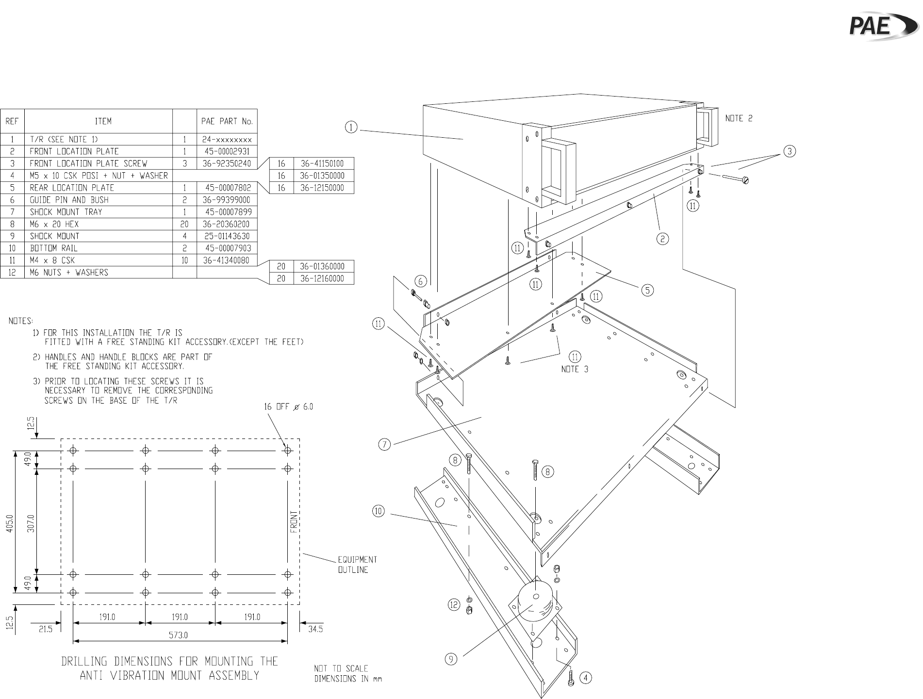
Anti-Vibration Mount Assembly
Fig. 7
(GA8528 Iss. 1)
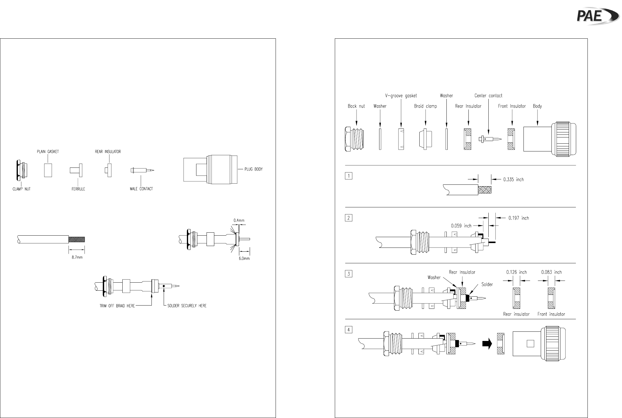
Assembly of N-Type Plugs
Fig. 8
(GA7883 Iss. 1 and GA7884 Iss. 1)
Assembly of N-Type Plug (Cable Clamp Type) Assembly of N-Type Plug (Braid Clamp Type)
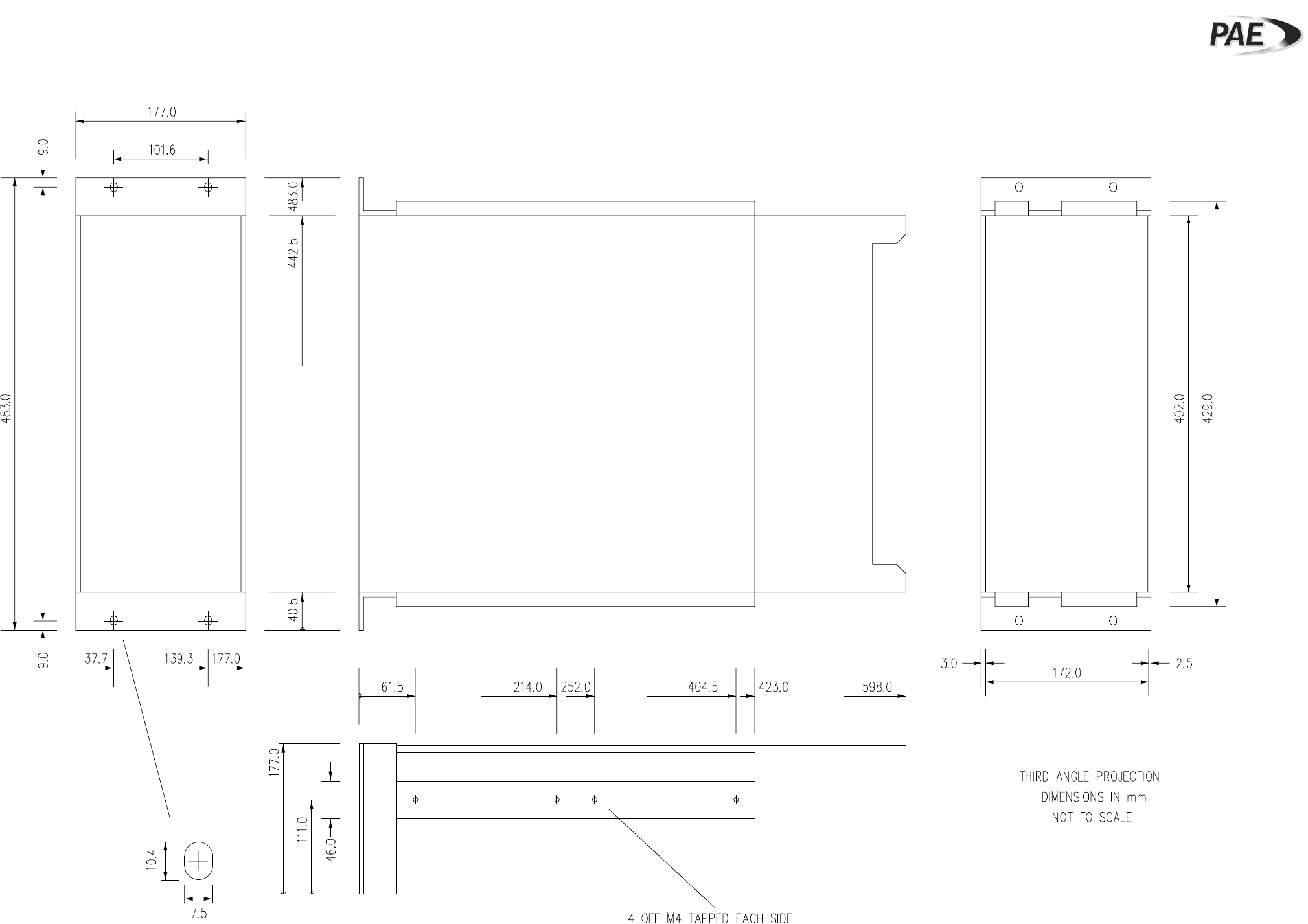
3000DV2 Overall Dimensions
Fig. 9
(GA7868 Iss. 1)