Park Air Systems B6100 VHF Fixed Ground Based Aeronautical Receiver User Manual T6R User Guide vp

Park Air Systems Limited VHF Fixed Ground Based Aeronautical Receiver T6R User Guide vp

Contents

Exhibit D User guide
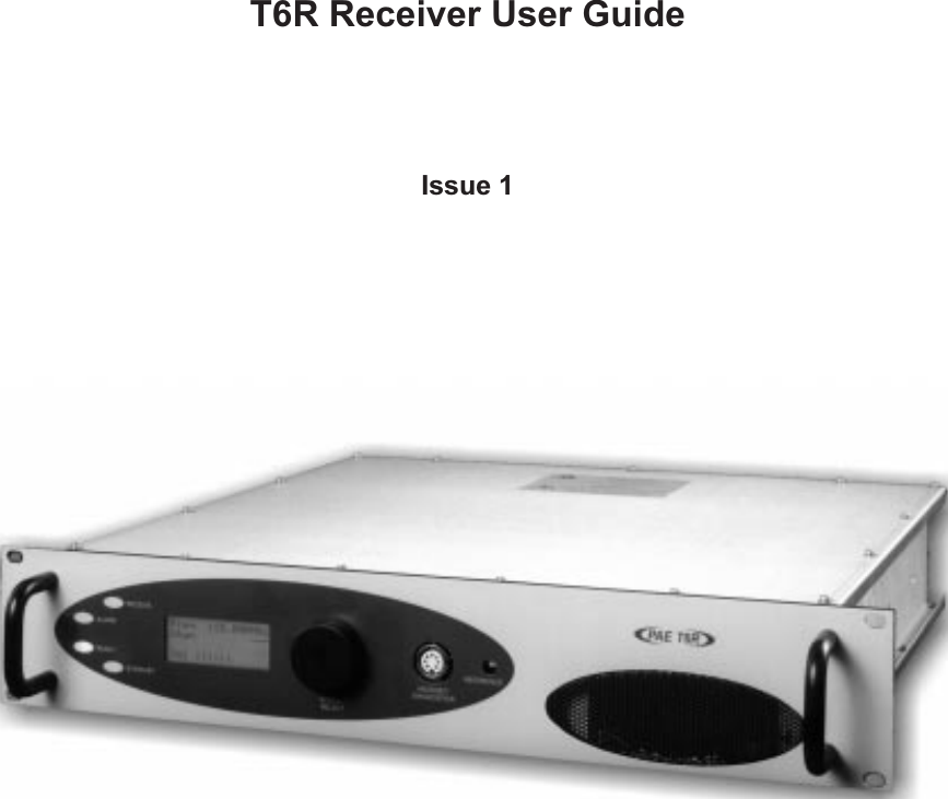
T6R Receiver User GuideIssue 1
Handbook Title: T6R Receiver User GuideHandbook Part Number: 31-360000RXIssue Number: 1Date of Issue: November 1999Published By: Park Air ElectronicsNorthfieldsMarket DeepingPeterboroughEngland PE6 8UETelephone: From UK, 01778 345434From outside UK, 44 1778 345434Fax: From UK, 01778 342877From outside UK, 44 1778 342877Page ii
Handbook Amendment RecordAmendments to this handbook, originated by Park Air Electronics, are listed in the following table.AmendmentNumber Date Brief Details PAE ChangeNote NumberEquipment Modification RecordModifications to the T6R receiver are detailed in the following table.The equipment’s modification label shows all modifications embodied in the equipment.ModificationNumber Date Brief Details PAE ChangeNote NumberPage iii
List of AbbreviationsThe following abbreviations are used in this user guide:Page ivA ampAM amplitude modulationBIT built-in testdB decibelDSP digital signal processingETI elapsed time indicatorICAO international civil aviation organisationkg kilogramkHz kilo HertzLCD liquid crystal displaymA milliampMARC multi-access remote control systemMHz mega Hertzmm millimetreppm parts per millionPSK phase shift keyingrms root mean squareRSSI receiver signal strength indicationV voltVFP virtual front panelVHF very high frequency
T6R Receiver User GuideSection 1General InformationT6R General Information Section 1Page 1
Section 1 T6R General InformationPage 2Section 1 ContentsChapter 1. OverviewIntroduction to the T6R Receiver 3T6R Handbooks 3Operational Settings 4Virtual Front Panel 5Built-In Tests 5Configuring the T6R Receiver 6Chapter 2. SpecificationDimensions and Weight 9RF Characteristics 9Environmental 9Power Requirements 10Chapter 3. Controls, Indicators, and ConnectorsFront Panel 11Receive Indicator 11Alarm Indicator 11Ready Indicator 11Standby Indicator 11Reference Connector 12Headset/Diagnostics Connector 12Scroll/Select Switch and LCD 13Rear Panel 14Power Switch 14AC Input Connector 14DC Input Connector 15Fuse F1 15Chassis Stud Connection 15Facilities Connector CN5 15MARC Port CN6 16Computer Port CN7 16Antenna Connector 16Chapter 4. Installation ProceduresIntroduction 21Initial Inspection of the Receiver 22Fitting the Correct AC Input Fuse 22Fitting a Radio into an Equipment Rack 23Connecting Remote Facilities 23Chassis Stud Connection 24AC Supply Connection 24DC Supply Connection 25Connecting an Antenna 25Switching on 25Page
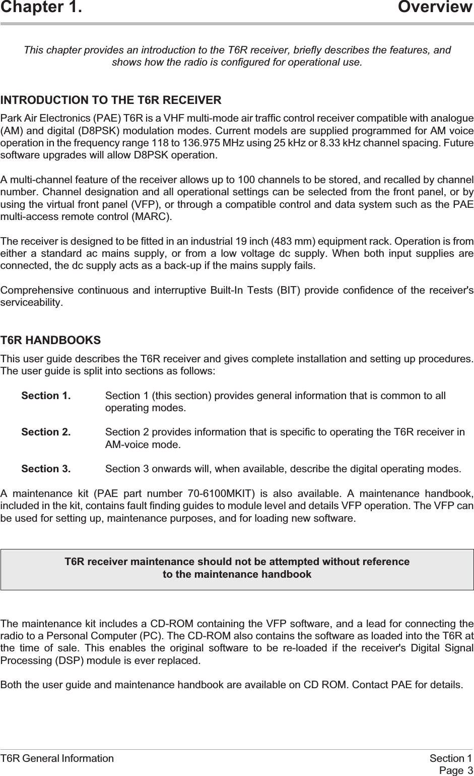
Chapter 1. OverviewThis chapter provides an introduction to the T6R receiver, briefly describes the features, andshows how the radio is configured for operational use.INTRODUCTION TO THE T6R RECEIVERPark Air Electronics (PAE) T6R is a VHF multi-mode air traffic control receiver compatible with analogue(AM) and digital (D8PSK) modulation modes. Current models are supplied programmed for AM voiceoperation in the frequency range 118 to 136.975 MHz using 25 kHz or 8.33 kHz channel spacing. Futuresoftware upgrades will allow D8PSK operation.A multi-channel feature of the receiver allows up to 100 channels to be stored, and recalled by channelnumber. Channel designation and all operational settings can be selected from the front panel, or byusing the virtual front panel (VFP), or through a compatible control and data system such as the PAEmulti-access remote control (MARC).The receiver is designed to be fitted in an industrial 19 inch (483 mm) equipment rack. Operation is fromeither a standard ac mains supply, or from a low voltage dc supply. When both input supplies areconnected, the dc supply acts as a back-up if the mains supply fails.Comprehensive continuous and interruptive Built-In Tests (BIT) provide confidence of the receiver'sserviceability.T6R HANDBOOKSThis user guide describes the T6R receiver and gives complete installation and setting up procedures.The user guide is split into sections as follows:Section 1. Section 1 (this section) provides general information that is common to alloperating modes.Section 2. Section 2 provides information that is specific to operating the T6R receiver inAM-voice mode.Section 3. Section 3 onwards will, when available, describe the digital operating modes.A maintenance kit (PAE part number 70-6100MKIT) is also available. A maintenance handbook,included in the kit, contains fault finding guides to module level and details VFP operation. The VFP canbe used for setting up, maintenance purposes, and for loading new software.The maintenance kit includes a CD-ROM containing the VFP software, and a lead for connecting theradio to a Personal Computer (PC). The CD-ROM also contains the software as loaded into the T6R atthe time of sale. This enables the original software to be re-loaded if the receiver's Digital SignalProcessing (DSP) module is ever replaced.Both the user guide and maintenance handbook are available on CD ROM. Contact PAE for details.T6R General Information Section 1Page 3T6R receiver maintenance should not be attempted without referenceto the maintenance handbook
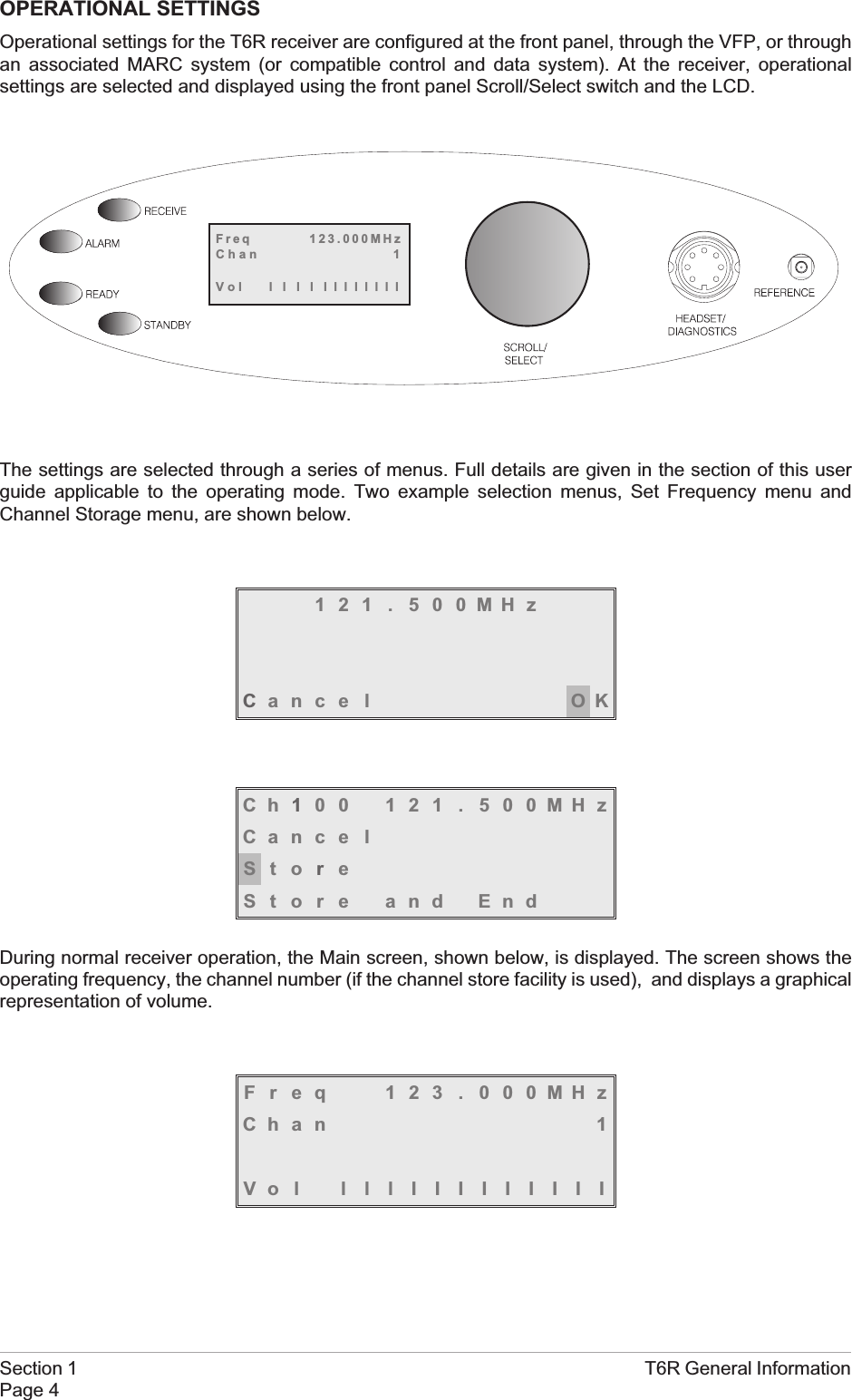
OPERATIONAL SETTINGSOperational settings for the T6R receiver are configured at the front panel, through the VFP, or throughan associated MARC system (or compatible control and data system). At the receiver, operationalsettings are selected and displayed using the front panel Scroll/Select switch and the LCD.The settings are selected through a series of menus. Full details are given in the section of this userguide applicable to the operating mode. Two example selection menus, Set Frequency menu andChannel Storage menu, are shown below.121 . 500MHzCance l OKCh100 121 . 500MHzCance lStoreStore and EndDuring normal receiver operation, the Main screen, shown below, is displayed. The screen shows theoperating frequency, the channel number (if the channel store facility is used), and displays a graphicalrepresentation of volume.Freq 123 . 000MHzChan 1Vol lllIIIIIIIIISection 1 T6R General InformationPage 4Freq 123.000MHzChan 1Vol llllllllllll
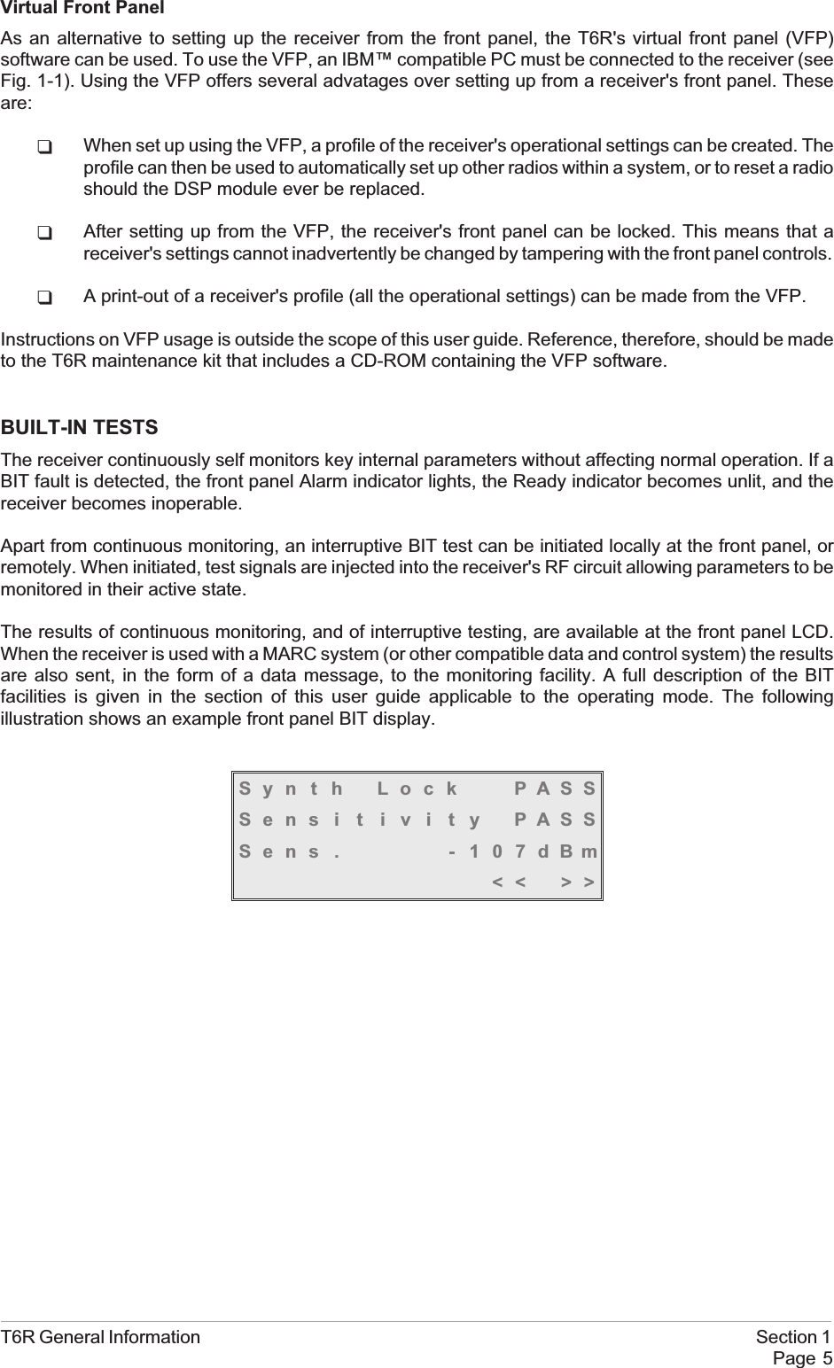
Virtual Front PanelAs an alternative to setting up the receiver from the front panel, the T6R's virtual front panel (VFP)software can be used. To use the VFP, an IBM™ compatible PC must be connected to the receiver (seeFig. 1-1). Using the VFP offers several advatages over setting up from a receiver's front panel. Theseare:qWhen set up using the VFP, a profile of the receiver's operational settings can be created. Theprofile can then be used to automatically set up other radios within a system, or to reset a radioshould the DSP module ever be replaced.qAfter setting up from the VFP, the receiver's front panel can be locked. This means that areceiver's settings cannot inadvertently be changed by tampering with the front panel controls.qA print-out of a receiver's profile (all the operational settings) can be made from the VFP.Instructions on VFP usage is outside the scope of this user guide. Reference, therefore, should be madeto the T6R maintenance kit that includes a CD-ROM containing the VFP software.BUILT-IN TESTSThe receiver continuously self monitors key internal parameters without affecting normal operation. If aBIT fault is detected, the front panel Alarm indicator lights, the Ready indicator becomes unlit, and thereceiver becomes inoperable.Apart from continuous monitoring, an interruptive BIT test can be initiated locally at the front panel, orremotely. When initiated, test signals are injected into the receiver's RF circuit allowing parameters to bemonitored in their active state.The results of continuous monitoring, and of interruptive testing, are available at the front panel LCD.When the receiver is used with a MARC system (or other compatible data and control system) the resultsare also sent, in the form of a data message, to the monitoring facility. A full description of the BITfacilities is given in the section of this user guide applicable to the operating mode. The followingillustration shows an example front panel BIT display.Syn t h Lock PASSSens i t i v i t y PASSSens . - 107dBm<< >>T6R General Information Section 1Page 5
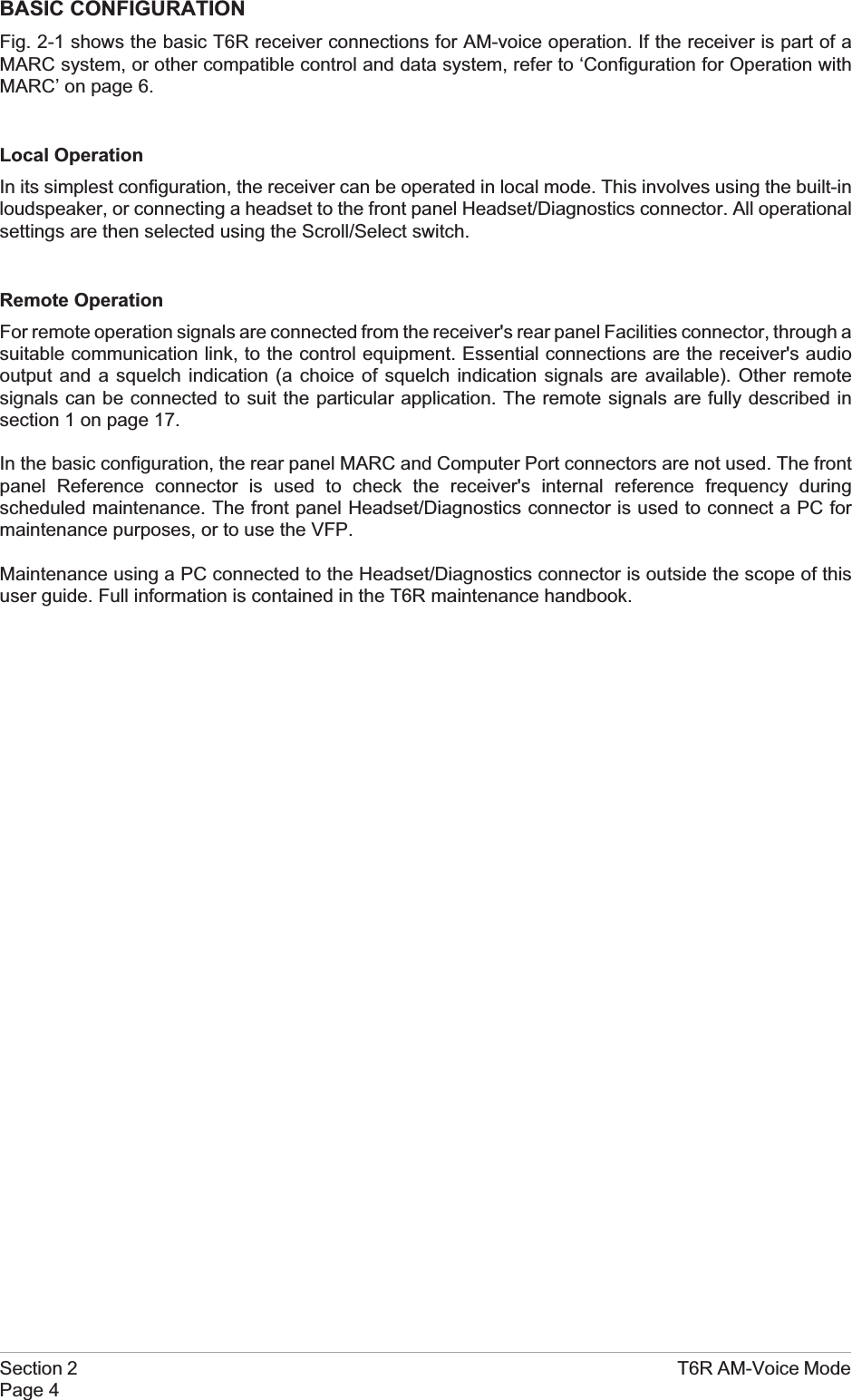
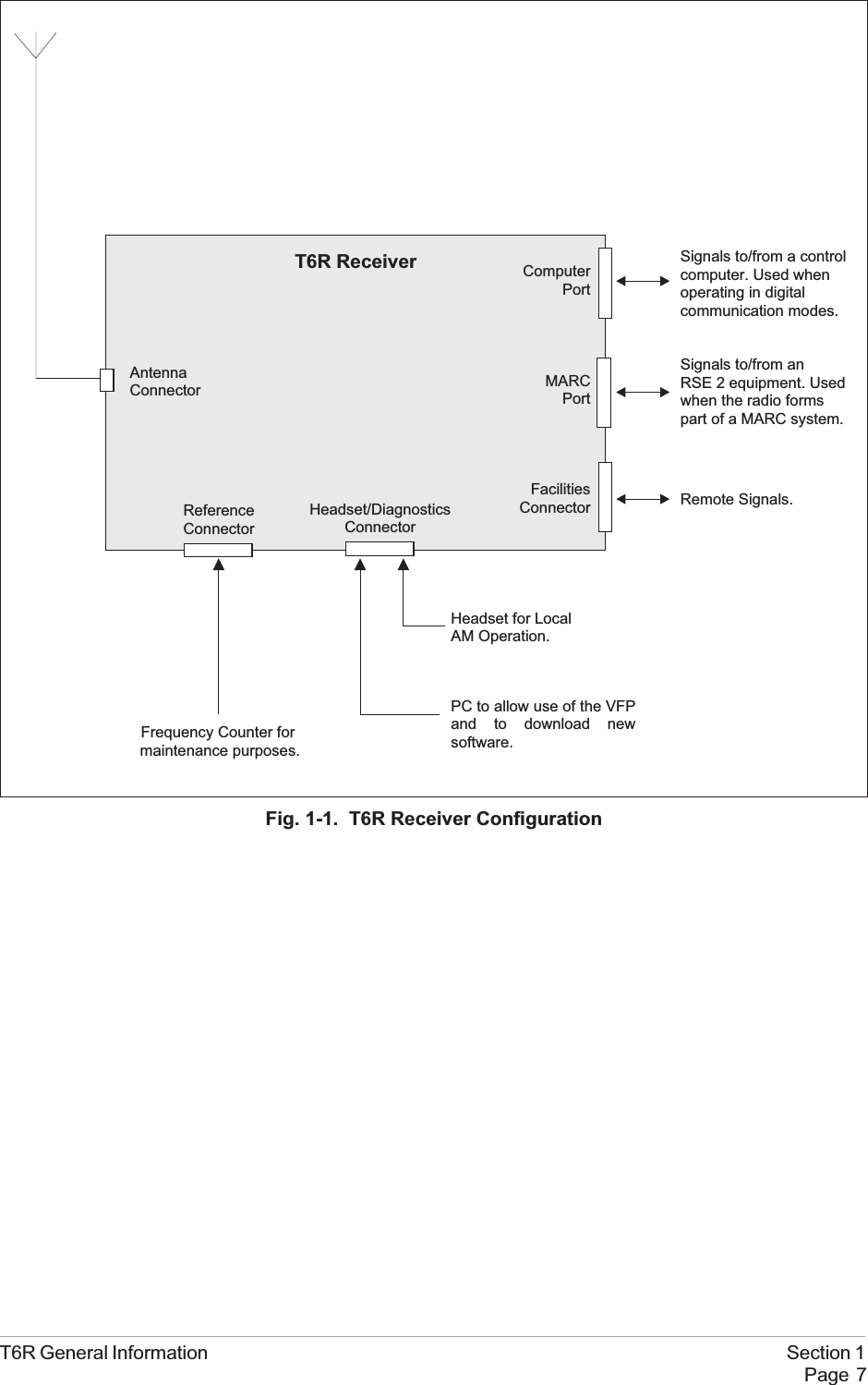
CONFIGURING THE T6R RECEIVERFig. 1-1 shows the signal connectors fitted to the receiver's front and rear panels. The connectors used toconfigure the receiver depend on the required operating mode. The purpose of each connector is brieflydescribed in the following paragraphs and fully detailed in chapter 3.Antenna Connector Used in all operating modes to connect the 50 ohm antenna feedercable.Headset/DiagnosticsConnectorThis is a dual purpose connector. A headset can be connected to enablelocal AM-voice operation.Alternatively, a PC can be connected to allow use of the VFP, to set thereceiver's operational settings, or to download new software.Reference Connector Used in all operating modes to check and reset the receiver's referencefrequency.Facilities Connector Used primarily to connect remote signals when using AM-voice modewhen the receiver does not form part of a MARC system.Some auxiliary signals available at this connector, for example the24 volt (nominal) unregulated output supply, can be utilized irrespectiveof the operating mode.MARC Port The MARC port is used to connect remote signals when the receiverforms part of a MARC system, or other compatible control and datasystem.Computer Port The computer port is used in digital communication modes to connectthe receiver to a control computer.Section 1 T6R General InformationPage 6
T6R General Information Section 1Page 7Fig. 1-1. T6R Receiver ConfigurationRemote Signals.Signals to/from a controlcomputer. Used whenoperating in digitalcommunication modes.Signals to/from anRSE 2 equipment. Usedwhen the radio formspart of a MARC system.T6R ReceiverAntennaConnectorFacilitiesConnectorComputerPortMARCPortHeadset for LocalAM Operation.PC to allow use of the VFPand to download newsoftware.Frequency Counter formaintenance purposes.Headset/DiagnosticsConnectorReferenceConnector
Intentionally BlankSection 1 T6R General InformationPage 8
Chapter 2. SpecificationThis chapter contains the T6R receiver's specification that is common to all operating modes.Specifications relevant to specific operating modes are contained in the section applicable to therequired operating mode.DIMENSIONS AND WEIGHTThe dimensions and weight of the T6R receiver are:Width 483 mm (19 inches).Height 88.9 mm (3.5 inches). The height occupies 2U ofequipment cabinet space.Depth (front panel to rear panel) 430 mm (16.9 inches).Weight 5.8 kg (12.8 pounds).RF CHARACTERISTICSFrequency range 118 to 136.975 MHz.Number of channels The receiver has a multi-channel capability.100 channels can be stored and recalled.Frequency accuracy Better than 1 ppm.Maximum RF input The receiver can withstand an input at the antennaconnector of:5 V rms continuous.15 V rms for 20 seconds.Unwanted signal suppression The first and second IF image rejection is greater than80 dB. For other frequencies, spurious signals aresuppressed by more than 100 dB.ENVIRONMENTALTemperature range The receiver operates to specification at temperaturesbetween -20 and +55°C and at a relative humiditybetween 5% and 90% (non-condensing).Warm up time The receiver is fully operational 5 seconds after switchon.Storage The receiver can be stored at temperatures between -30and +70°C without causing damage.T6R General Information Section 1Page 9
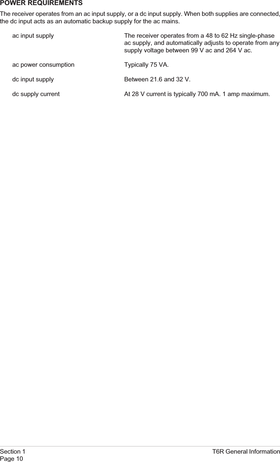
POWER REQUIREMENTSThe receiver operates from an ac input supply, or a dc input supply. When both supplies are connected,the dc input acts as an automatic backup supply for the ac mains.ac input supply The receiver operates from a 48 to 62 Hz single-phaseac supply, and automatically adjusts to operate from anysupply voltage between 99 V ac and 264 V ac.ac power consumption Typically 75 VA.dc input supply Between 21.6 and 32 V.dc supply current At 28 V current is typically 700 mA. 1 amp maximum.Section 1 T6R General InformationPage 10
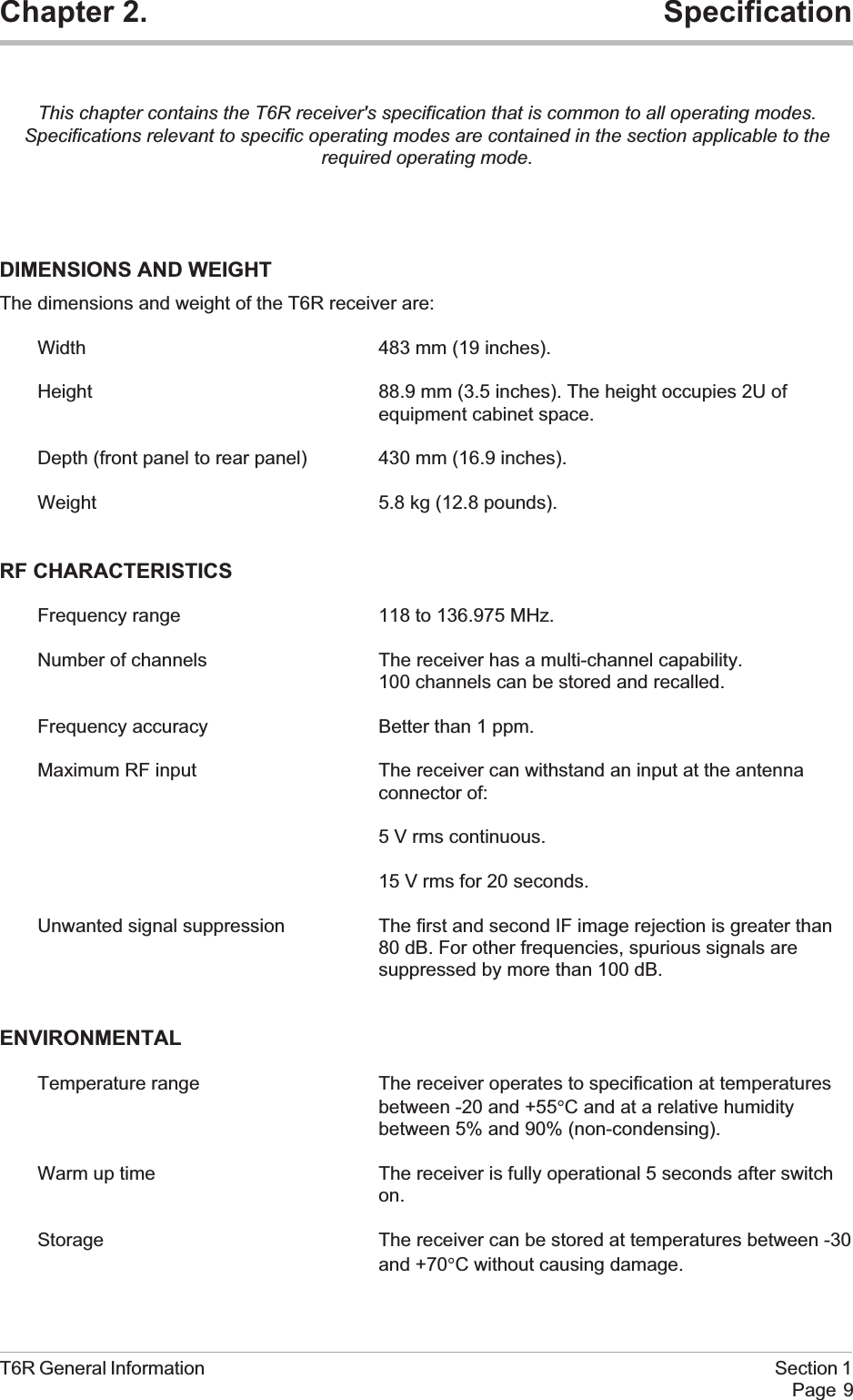
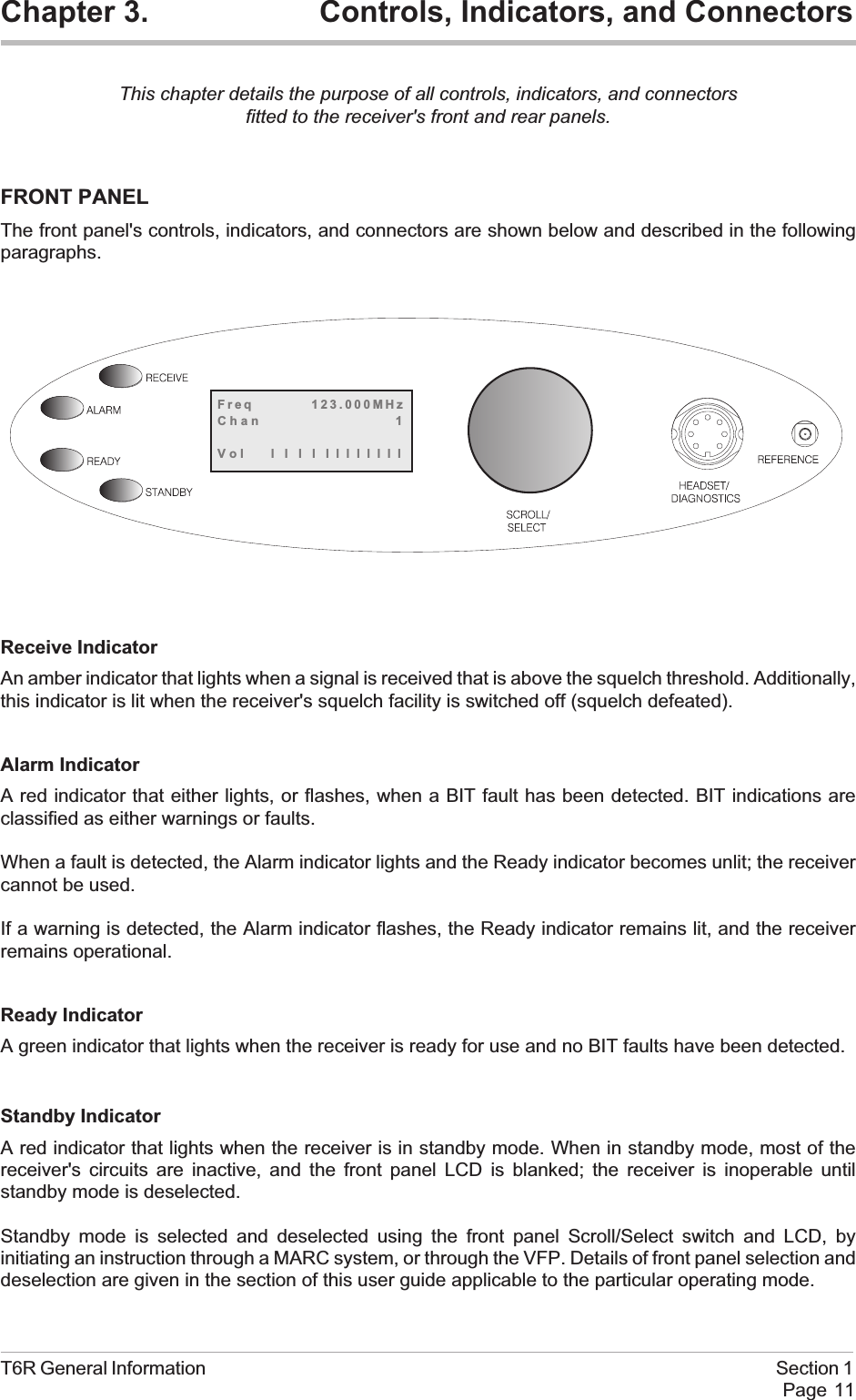
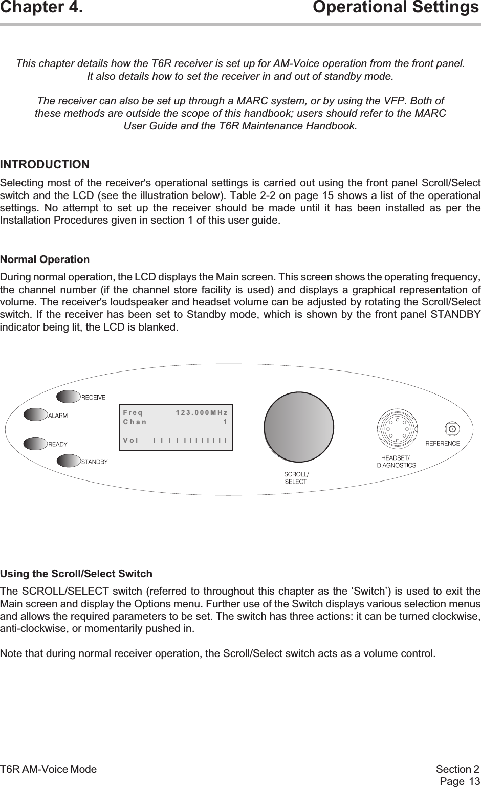
Chapter 3. Controls, Indicators, and ConnectorsThis chapter details the purpose of all controls, indicators, and connectorsfitted to the receiver's front and rear panels.FRONT PANELThe front panel's controls, indicators, and connectors are shown below and described in the followingparagraphs.Receive IndicatorAn amber indicator that lights when a signal is received that is above the squelch threshold. Additionally,this indicator is lit when the receiver's squelch facility is switched off (squelch defeated).Alarm IndicatorA red indicator that either lights, or flashes, when a BIT fault has been detected. BIT indications areclassified as either warnings or faults.When a fault is detected, the Alarm indicator lights and the Ready indicator becomes unlit; the receivercannot be used.If a warning is detected, the Alarm indicator flashes, the Ready indicator remains lit, and the receiverremains operational.Ready IndicatorA green indicator that lights when the receiver is ready for use and no BIT faults have been detected.Standby IndicatorA red indicator that lights when the receiver is in standby mode. When in standby mode, most of thereceiver's circuits are inactive, and the front panel LCD is blanked; the receiver is inoperable untilstandby mode is deselected.Standby mode is selected and deselected using the front panel Scroll/Select switch and LCD, byinitiating an instruction through a MARC system, or through the VFP. Details of front panel selection anddeselection are given in the section of this user guide applicable to the particular operating mode.T6R General Information Section 1Page 11Freq 123.000MHzChan 1Vol llllllllllll
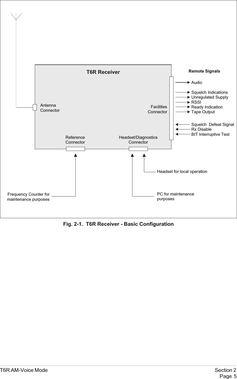
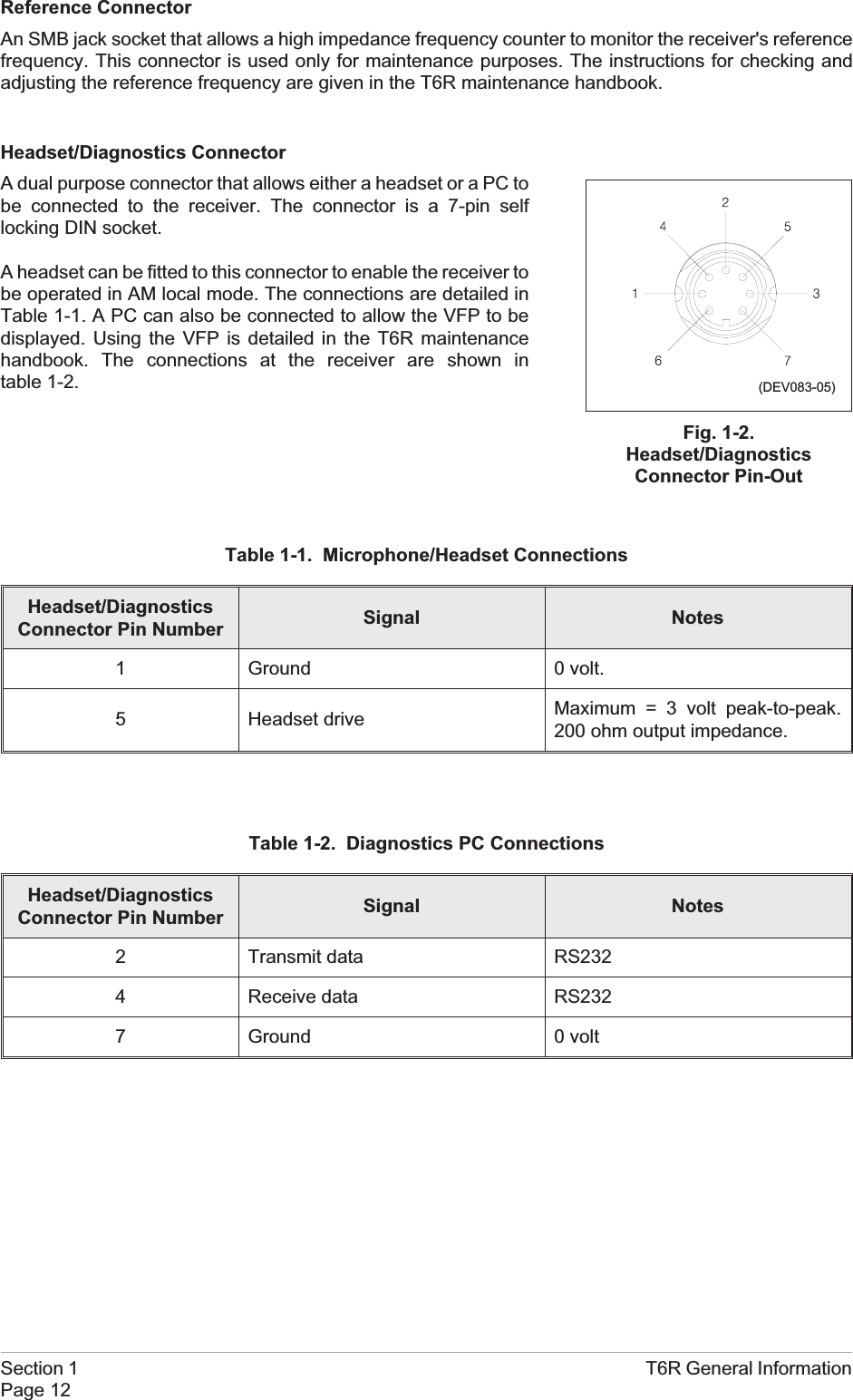
Reference ConnectorAn SMB jack socket that allows a high impedance frequency counter to monitor the receiver's referencefrequency. This connector is used only for maintenance purposes. The instructions for checking andadjusting the reference frequency are given in the T6R maintenance handbook.Headset/Diagnostics ConnectorA dual purpose connector that allows either a headset or a PC tobe connected to the receiver. The connector is a 7-pin selflocking DIN socket.A headset can be fitted to this connector to enable the receiver tobe operated in AM local mode. The connections are detailed inTable 1-1. A PC can also be connected to allow the VFP to bedisplayed. Using the VFP is detailed in the T6R maintenancehandbook. The connections at the receiver are shown intable 1-2.Table 1-1. Microphone/Headset ConnectionsHeadset/DiagnosticsConnector Pin Number Signal Notes1 Ground 0 volt.5 Headset drive Maximum = 3 volt peak-to-peak.200 ohm output impedance.Table 1-2. Diagnostics PC ConnectionsHeadset/DiagnosticsConnector Pin Number Signal Notes2 Transmit data RS2324 Receive data RS2327 Ground 0 voltSection 1 T6R General InformationPage 12Fig. 1-2.Headset/DiagnosticsConnector Pin-Out(DEV083-05)
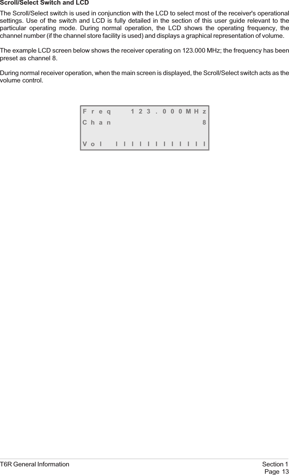
Scroll/Select Switch and LCDThe Scroll/Select switch is used in conjunction with the LCD to select most of the receiver's operationalsettings. Use of the switch and LCD is fully detailed in the section of this user guide relevant to theparticular operating mode. During normal operation, the LCD shows the operating frequency, thechannel number (if the channel store facility is used) and displays a graphical representation of volume.The example LCD screen below shows the receiver operating on 123.000 MHz; the frequency has beenpreset as channel 8.During normal receiver operation, when the main screen is displayed, the Scroll/Select switch acts as thevolume control.Freq 123 . 000MHzChan 8Vol llllIIIIIIIIT6R General Information Section 1Page 13
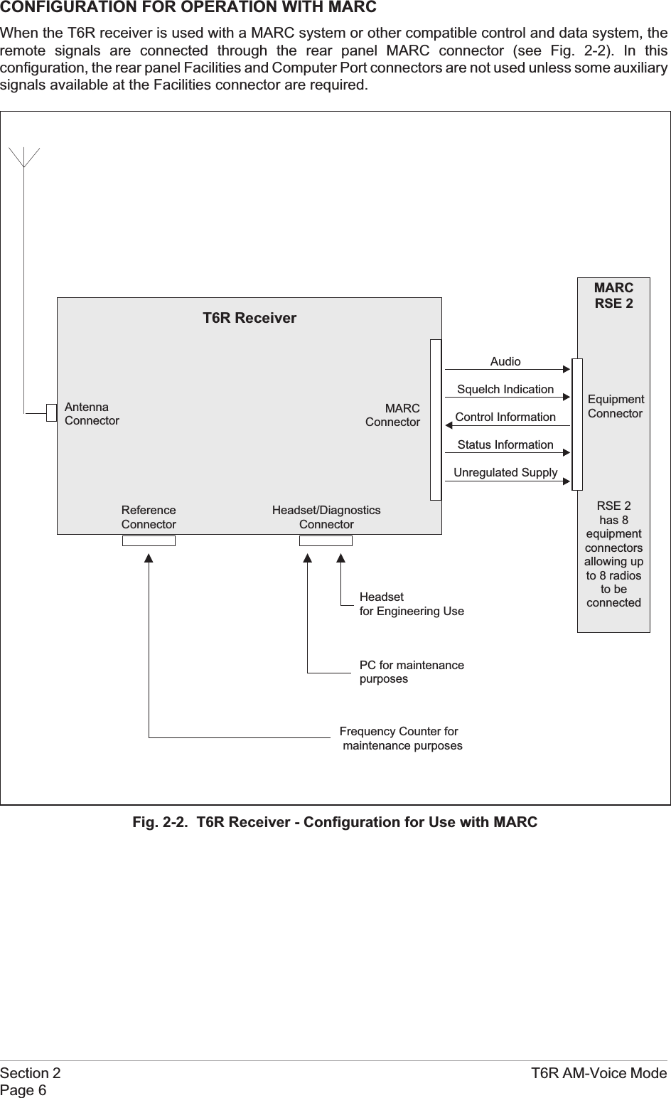
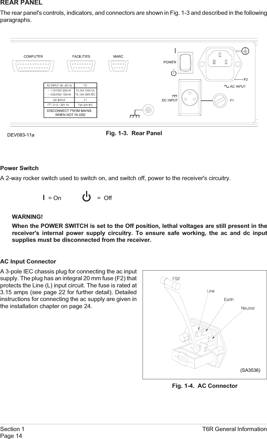
REAR PANELThe rear panel's controls, indicators, and connectors are shown in Fig. 1-3 and described in the followingparagraphs.Power SwitchA 2-way rocker switch used to switch on, and switch off, power to the receiver's circuitry.l=OnWARNING!When the POWER SWITCH is set to the Off position, lethal voltages are still present in thereceiver's internal power supply circuitry. To ensure safe working, the ac and dc inputsupplies must be disconnected from the receiver.AC Input ConnectorA 3-pole IEC chassis plug for connecting the ac inputsupply. The plug has an integral 20 mm fuse (F2) thatprotects the Line (L) input circuit. The fuse is rated at3.15 amps (see page 22 for further detail). Detailedinstructions for connecting the ac supply are given inthe installation chapter on page 24.Section 1 T6R General InformationPage 14= OffFig. 1-4. AC Connector(SA3536)Fig. 1-3. Rear PanelDEV083-11a
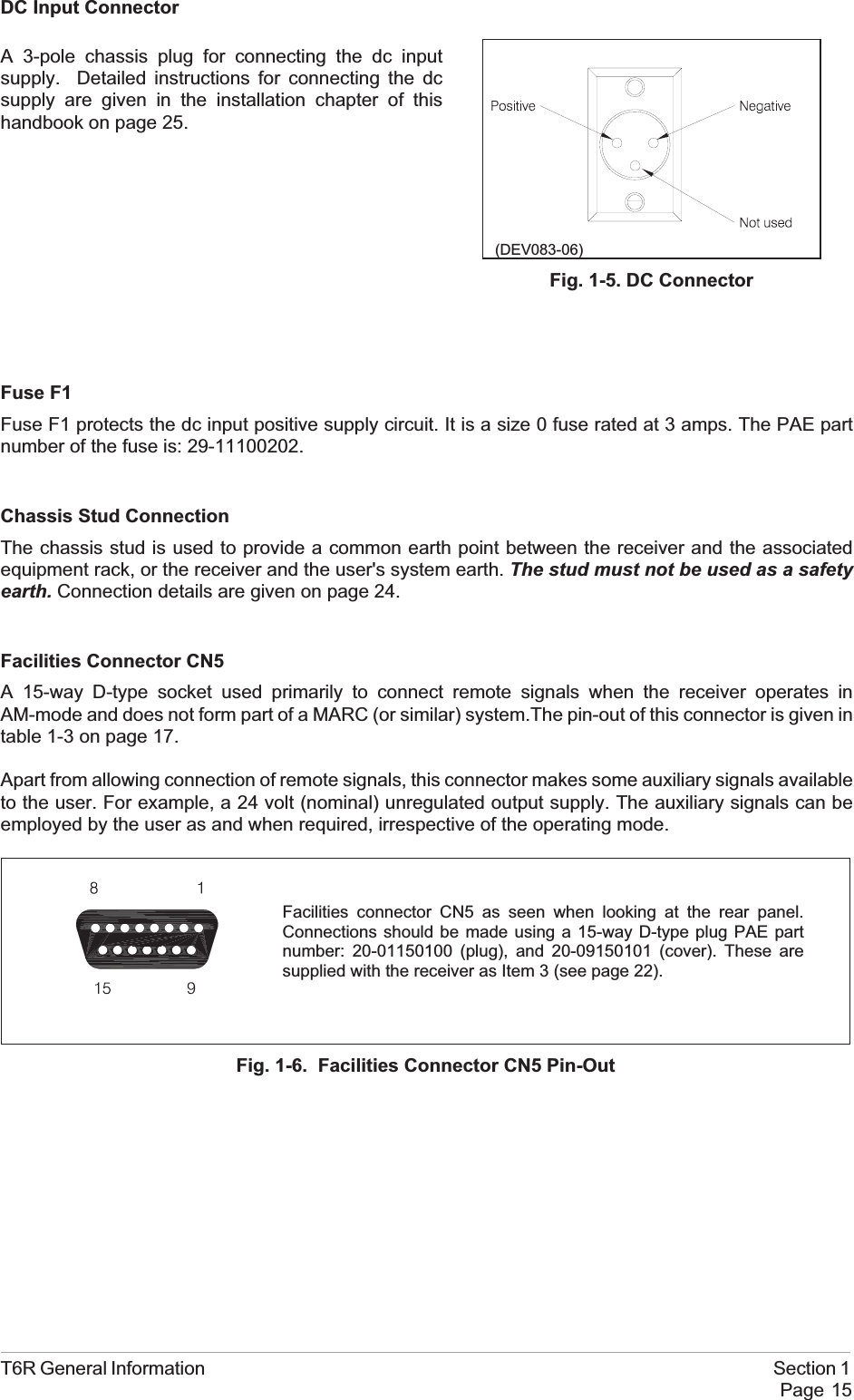
DC Input ConnectorFuse F1Fuse F1 protects the dc input positive supply circuit. It is a size 0 fuse rated at 3 amps. The PAE partnumber of the fuse is: 29-11100202.Chassis Stud ConnectionThe chassis stud is used to provide a common earth point between the receiver and the associatedequipment rack, or the receiver and the user's system earth. The stud must not be used as a safetyearth. Connection details are given on page 24.Facilities Connector CN5A 15-way D-type socket used primarily to connect remote signals when the receiver operates inAM-mode and does not form part of a MARC (or similar) system.The pin-out of this connector is given intable 1-3 on page 17.Apart from allowing connection of remote signals, this connector makes some auxiliary signals availableto the user. For example, a 24 volt (nominal) unregulated output supply. The auxiliary signals can beemployed by the user as and when required, irrespective of the operating mode.T6R General Information Section 1Page 15Facilities connector CN5 as seen when looking at the rear panel.Connections should be made using a 15-way D-type plug PAE partnumber: 20-01150100 (plug), and 20-09150101 (cover). These aresupplied with the receiver as Item 3 (see page 22).Fig. 1-6. Facilities Connector CN5 Pin-Out(DEV083-06)Fig. 1-5. DC ConnectorA 3-pole chassis plug for connecting the dc inputsupply. Detailed instructions for connecting the dcsupply are given in the installation chapter of thishandbook on page 25.
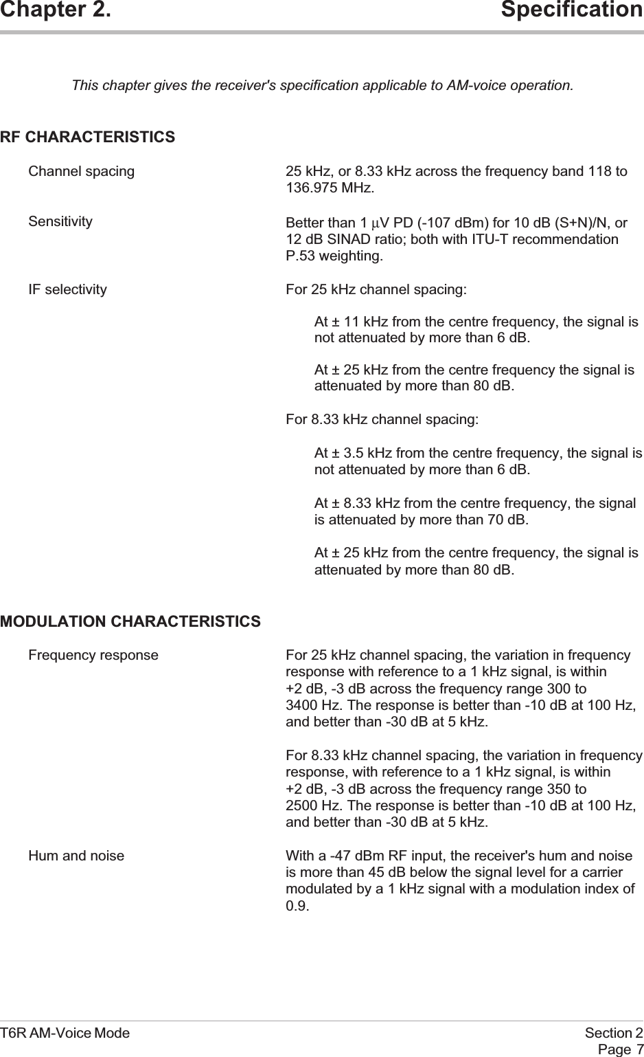
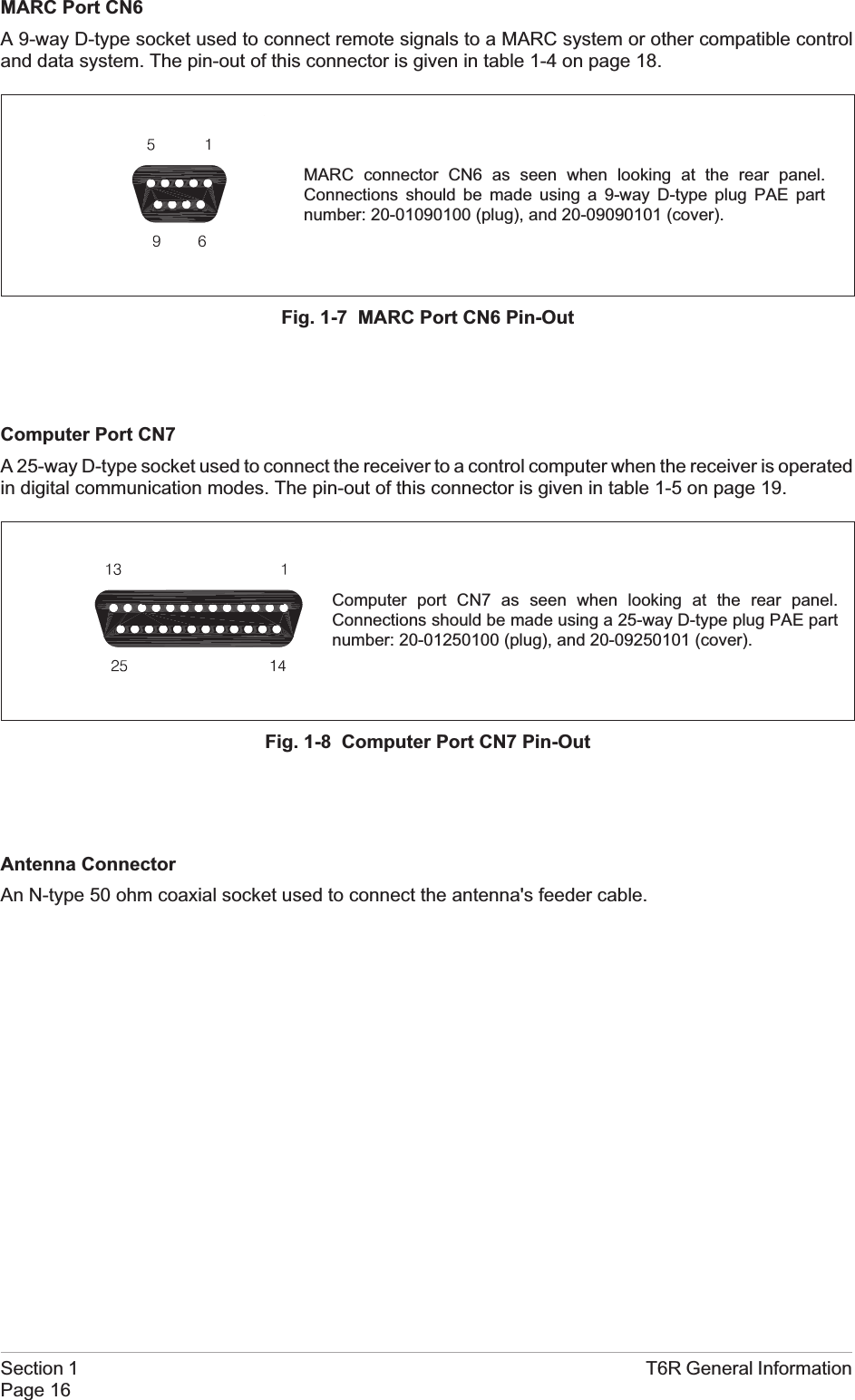
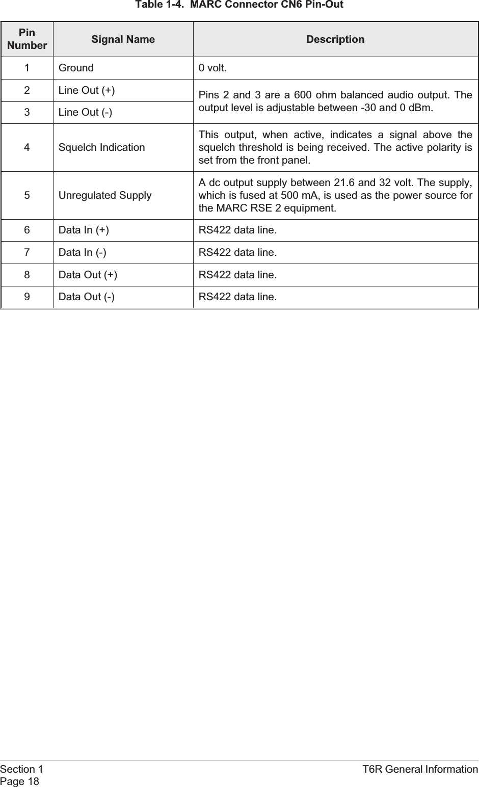
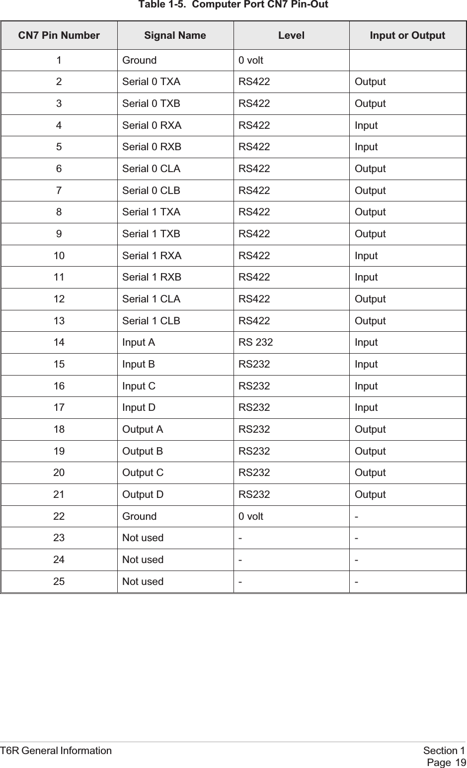
MARC Port CN6A 9-way D-type socket used to connect remote signals to a MARC system or other compatible controland data system. The pin-out of this connector is given in table 1-4 on page 18.Computer Port CN7A 25-way D-type socket used to connect the receiver to a control computer when the receiver is operatedin digital communication modes. The pin-out of this connector is given in table 1-5 on page 19.Antenna ConnectorAn N-type 50 ohm coaxial socket used to connect the antenna's feeder cable.Section 1 T6R General InformationPage 16Fig. 1-7 MARC Port CN6 Pin-OutMARC connector CN6 as seen when looking at the rear panel.Connections should be made using a 9-way D-type plug PAE partnumber: 20-01090100 (plug), and 20-09090101 (cover).Fig. 1-8 Computer Port CN7 Pin-OutComputer port CN7 as seen when looking at the rear panel.Connections should be made using a 25-way D-type plug PAE partnumber: 20-01250100 (plug), and 20-09250101 (cover).
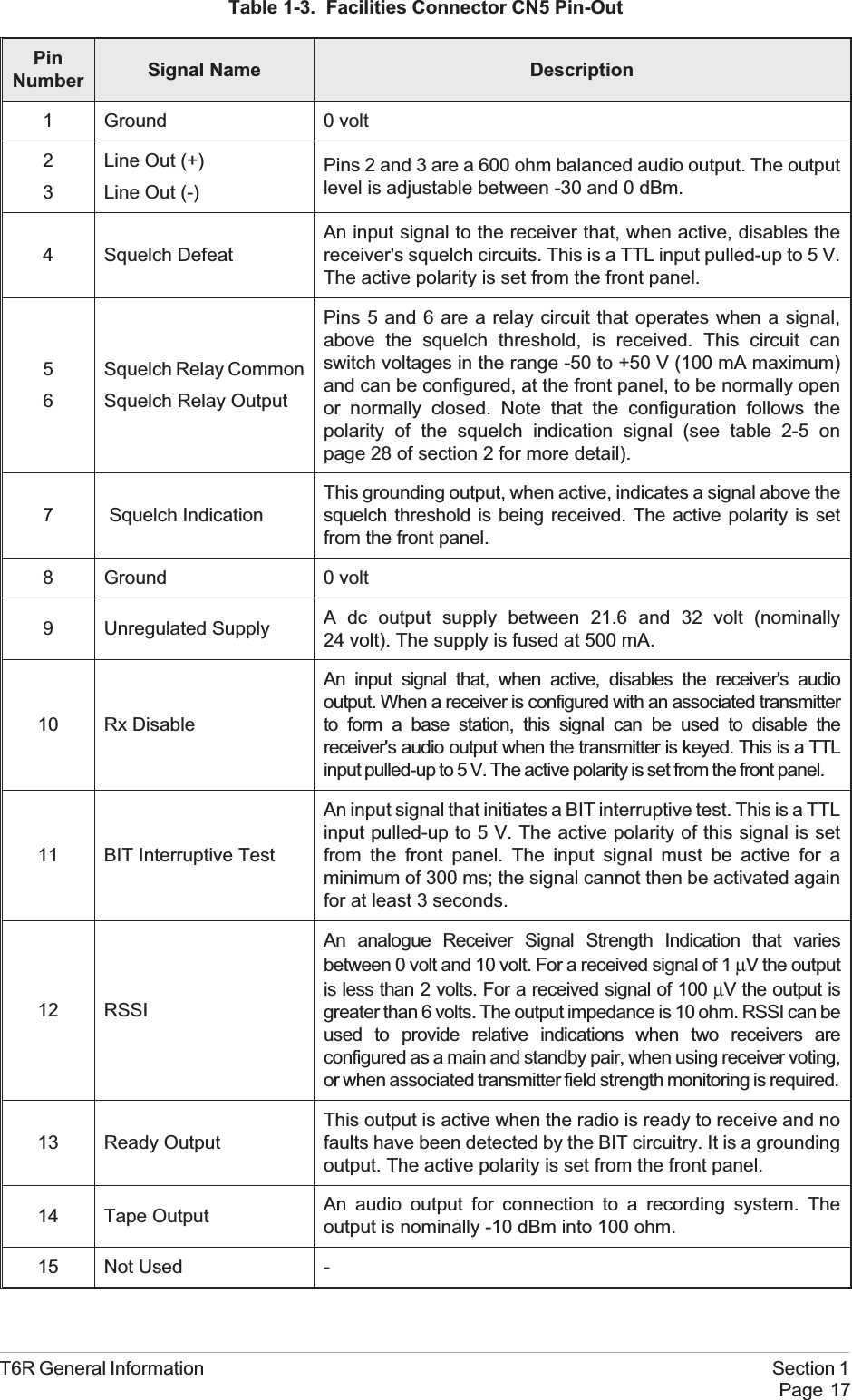
Table 1-3. Facilities Connector CN5 Pin-OutPinNumber Signal Name Description1 Ground 0 volt23Line Out (+)Line Out (-)Pins 2 and 3 are a 600 ohm balanced audio output. The outputlevel is adjustable between -30 and 0 dBm.4 Squelch DefeatAn input signal to the receiver that, when active, disables thereceiver's squelch circuits. This is a TTL input pulled-up to 5 V.The active polarity is set from the front panel.56Squelch Relay CommonSquelch Relay OutputPins 5 and 6 are a relay circuit that operates when a signal,above the squelch threshold, is received. This circuit canswitch voltages in the range -50 to +50 V (100 mA maximum)and can be configured, at the front panel, to be normally openor normally closed. Note that the configuration follows thepolarity of the squelch indication signal (see table 2-5 onpage 28 of section 2 for more detail).7 Squelch IndicationThis grounding output, when active, indicates a signal above thesquelch threshold is being received. The active polarity is setfrom the front panel.8 Ground 0 volt9 Unregulated Supply A dc output supply between 21.6 and 32 volt (nominally24 volt). The supply is fused at 500 mA.10 Rx DisableAn input signal that, when active, disables the receiver's audiooutput. When a receiver is configured with an associated transmitterto form a base station, this signal can be used to disable thereceiver's audio output when the transmitter is keyed. This is a TTLinput pulled-up to 5 V. The active polarity is set from the front panel.11 BIT Interruptive TestAn input signal that initiates a BIT interruptive test. This is a TTLinput pulled-up to 5 V. The active polarity of this signal is setfrom the front panel. The input signal must be active for aminimum of 300 ms; the signal cannot then be activated againfor at least 3 seconds.12 RSSIAn analogue Receiver Signal Strength Indication that variesbetween 0 volt and 10 volt. For a received signal of 1 µV the outputis less than 2 volts. For a received signal of 100 µV the output isgreater than 6 volts. The output impedance is 10 ohm. RSSI can beused to provide relative indications when two receivers areconfigured as a main and standby pair, when using receiver voting,or when associated transmitter field strength monitoring is required.13 Ready OutputThis output is active when the radio is ready to receive and nofaults have been detected by the BIT circuitry. It is a groundingoutput. The active polarity is set from the front panel.14 Tape Output An audio output for connection to a recording system. Theoutput is nominally -10 dBm into 100 ohm.15 Not Used -T6R General Information Section 1Page 17
Table 1-4. MARC Connector CN6 Pin-OutPinNumber Signal Name Description1 Ground 0 volt.2 Line Out (+) Pins 2 and 3 are a 600 ohm balanced audio output. Theoutput level is adjustable between -30 and 0 dBm.3 Line Out (-)4 Squelch IndicationThis output, when active, indicates a signal above thesquelch threshold is being received. The active polarity isset from the front panel.5 Unregulated SupplyA dc output supply between 21.6 and 32 volt. The supply,which is fused at 500 mA, is used as the power source forthe MARC RSE 2 equipment.6 Data In (+) RS422 data line.7 Data In (-) RS422 data line.8 Data Out (+) RS422 data line.9 Data Out (-) RS422 data line.Section 1 T6R General InformationPage 18
Table 1-5. Computer Port CN7 Pin-OutCN7 Pin Number Signal Name Level Input or Output1 Ground 0 volt2 Serial 0 TXA RS422 Output3 Serial 0 TXB RS422 Output4 Serial 0 RXA RS422 Input5 Serial 0 RXB RS422 Input6 Serial 0 CLA RS422 Output7 Serial 0 CLB RS422 Output8 Serial 1 TXA RS422 Output9 Serial 1 TXB RS422 Output10 Serial 1 RXA RS422 Input11 Serial 1 RXB RS422 Input12 Serial 1 CLA RS422 Output13 Serial 1 CLB RS422 Output14 Input A RS 232 Input15 Input B RS232 Input16 Input C RS232 Input17 Input D RS232 Input18 Output A RS232 Output19 Output B RS232 Output20 Output C RS232 Output21 Output D RS232 Output22 Ground 0 volt -23 Not used - -24 Not used - -25 Not used - -T6R General Information Section 1Page 19
Intentionally BlankSection 1 T6R General InformationPage 20
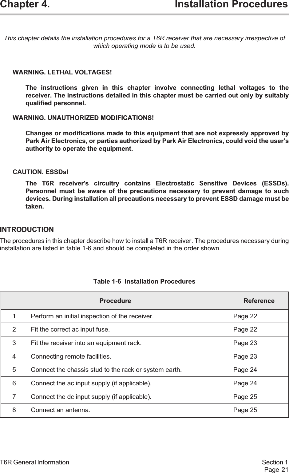
Chapter 4. Installation ProceduresThis chapter details the installation procedures for a T6R receiver that are necessary irrespective ofwhich operating mode is to be used.WARNING. LETHAL VOLTAGES!The instructions given in this chapter involve connecting lethal voltages to thereceiver. The instructions detailed in this chapter must be carried out only by suitablyqualified personnel.WARNING. UNAUTHORIZED MODIFICATIONS!Changes or modifications made to this equipment that are not expressly approved byPark Air Electronics, or parties authorized by Park Air Electronics, could void the user’sauthority to operate the equipment.CAUTION. ESSDs!The T6R receiver's circuitry contains Electrostatic Sensitive Devices (ESSDs).Personnel must be aware of the precautions necessary to prevent damage to suchdevices. During installation all precautions necessary to prevent ESSD damage must betaken.INTRODUCTIONThe procedures in this chapter describe how to install a T6R receiver. The procedures necessary duringinstallation are listed in table 1-6 and should be completed in the order shown.Table 1-6 Installation ProceduresProcedure Reference1 Perform an initial inspection of the receiver. Page 222 Fit the correct ac input fuse. Page 223 Fit the receiver into an equipment rack. Page 234 Connecting remote facilities. Page 235 Connect the chassis stud to the rack or system earth. Page 246 Connect the ac input supply (if applicable). Page 247 Connect the dc input supply (if applicable). Page 258 Connect an antenna. Page 25T6R General Information Section 1Page 21
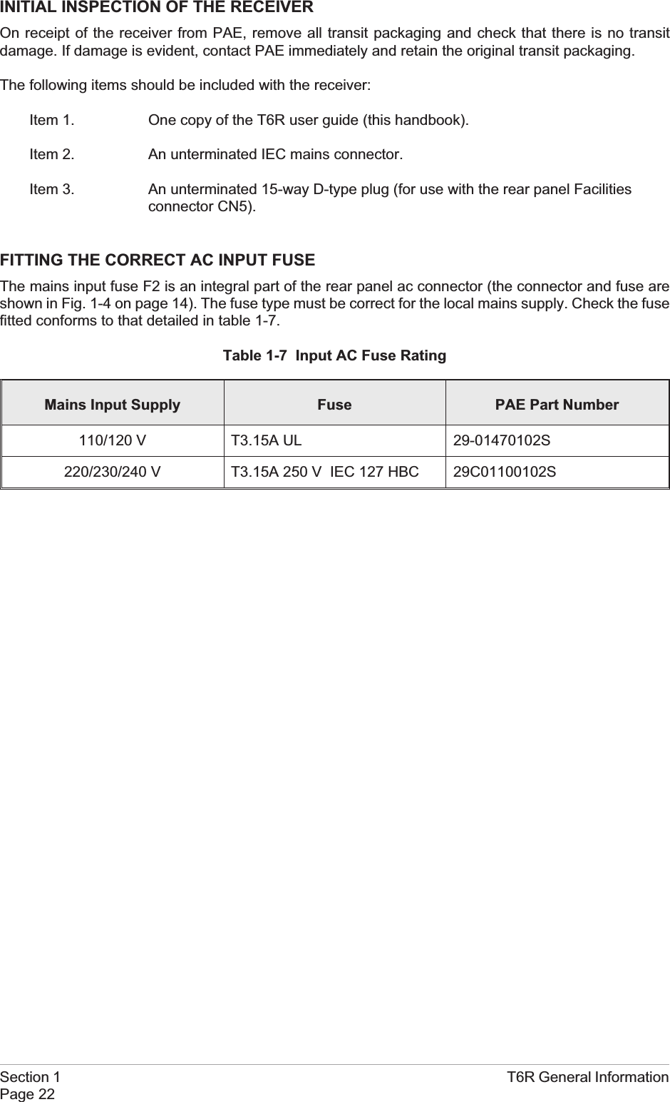
INITIAL INSPECTION OF THE RECEIVEROn receipt of the receiver from PAE, remove all transit packaging and check that there is no transitdamage. If damage is evident, contact PAE immediately and retain the original transit packaging.The following items should be included with the receiver:Item 1. One copy of the T6R user guide (this handbook).Item 2. An unterminated IEC mains connector.Item 3. An unterminated 15-way D-type plug (for use with the rear panel Facilitiesconnector CN5).FITTING THE CORRECT AC INPUT FUSEThe mains input fuse F2 is an integral part of the rear panel ac connector (the connector and fuse areshown in Fig. 1-4 on page 14). The fuse type must be correct for the local mains supply. Check the fusefitted conforms to that detailed in table 1-7.Table 1-7 Input AC Fuse RatingMains Input Supply Fuse PAE Part Number110/120 V T3.15A UL 29-01470102S220/230/240 V T3.15A 250 V IEC 127 HBC 29C01100102SSection 1 T6R General InformationPage 22
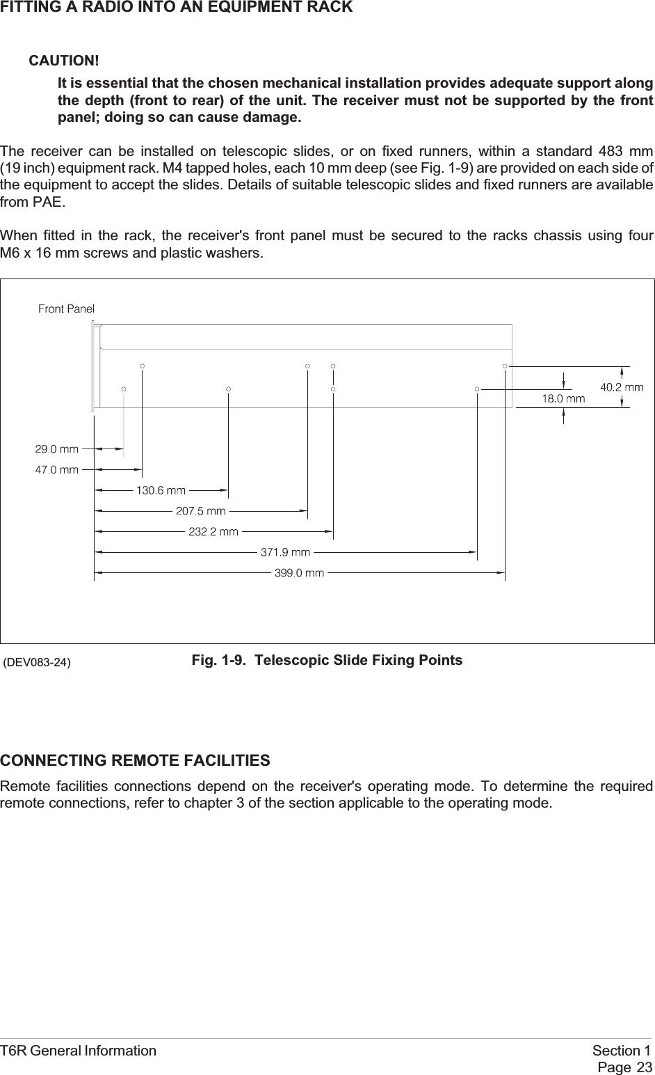
FITTING A RADIO INTO AN EQUIPMENT RACKCAUTION!It is essential that the chosen mechanical installation provides adequate support alongthe depth (front to rear) of the unit. The receiver must not be supported by the frontpanel; doing so can cause damage.The receiver can be installed on telescopic slides, or on fixed runners, within a standard 483 mm(19 inch) equipment rack. M4 tapped holes, each 10 mm deep (see Fig. 1-9) are provided on each side ofthe equipment to accept the slides. Details of suitable telescopic slides and fixed runners are availablefrom PAE.When fitted in the rack, the receiver's front panel must be secured to the racks chassis using fourM6 x 16 mm screws and plastic washers.CONNECTING REMOTE FACILITIESRemote facilities connections depend on the receiver's operating mode. To determine the requiredremote connections, refer to chapter 3 of the section applicable to the operating mode.T6R General Information Section 1Page 23Fig. 1-9. Telescopic Slide Fixing Points(DEV083-24)
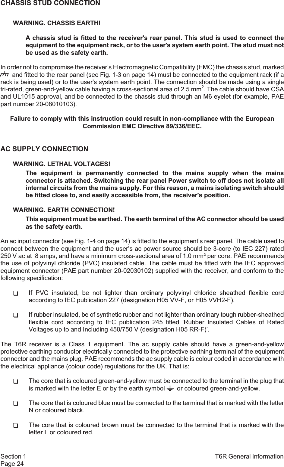
CHASSIS STUD CONNECTIONWARNING. CHASSIS EARTH!A chassis stud is fitted to the receiver's rear panel. This stud is used to connect theequipment to the equipment rack, or to the user's system earth point. The stud must notbe used as the safety earth.In order not to compromise the receiver’s Electromagnetic Compatibility (EMC) the chassis stud, markedand fitted to the rear panel (see Fig. 1-3 on page 14) must be connected to the equipment rack (if arack is being used) or to the user's system earth point. The connection should be made using a singletri-rated, green-and-yellow cable having a cross-sectional area of 2.5 mm2. The cable should have CSAand UL1015 approval, and be connected to the chassis stud through an M6 eyelet (for example, PAEpart number 20-08010103).Failure to comply with this instruction could result in non-compliance with the EuropeanCommission EMC Directive 89/336/EEC.AC SUPPLY CONNECTIONWARNING. LETHAL VOLTAGES!The equipment is permanently connected to the mains supply when the mainsconnector is attached. Switching the rear panel Power switch to off does not isolate allinternal circuits from the mains supply. For this reason, a mains isolating switch shouldbe fitted close to, and easily accessible from, the receiver's position.WARNING. EARTH CONNECTION!This equipment must be earthed. The earth terminal of the AC connector should be usedas the safety earth.An ac input connector (see Fig. 1-4 on page 14) is fitted to the equipment’s rear panel. The cable used toconnect between the equipment and the user’s ac power source should be 3-core (to IEC 227) rated250 V ac at 8 amps, and have a minimum cross-sectional area of 1.0 mm² per core. PAE recommendsthe use of polyvinyl chloride (PVC) insulated cable. The cable must be fitted with the IEC approvedequipment connector (PAE part number 20-02030102) supplied with the receiver, and conform to thefollowing specification:qIf PVC insulated, be not lighter than ordinary polyvinyl chloride sheathed flexible cordaccording to IEC publication 227 (designation H05 VV-F, or H05 VVH2-F).qIf rubber insulated, be of synthetic rubber and not lighter than ordinary tough rubber-sheathedflexible cord according to IEC publication 245 titled ‘Rubber Insulated Cables of RatedVoltages up to and Including 450/750 V (designation H05 RR-F)’.The T6R receiver is a Class 1 equipment. The ac supply cable should have a green-and-yellowprotective earthing conductor electrically connected to the protective earthing terminal of the equipmentconnector and the mains plug. PAE recommends the ac supply cable is colour coded in accordance withthe electrical appliance (colour code) regulations for the UK. That is:qThe core that is coloured green-and-yellow must be connected to the terminal in the plug thatis marked with the letter E or by the earth symbol or coloured green-and-yellow.qThe core that is coloured blue must be connected to the terminal that is marked with the letterN or coloured black.qThe core that is coloured brown must be connected to the terminal that is marked with theletter L or coloured red.Section 1 T6R General InformationPage 24
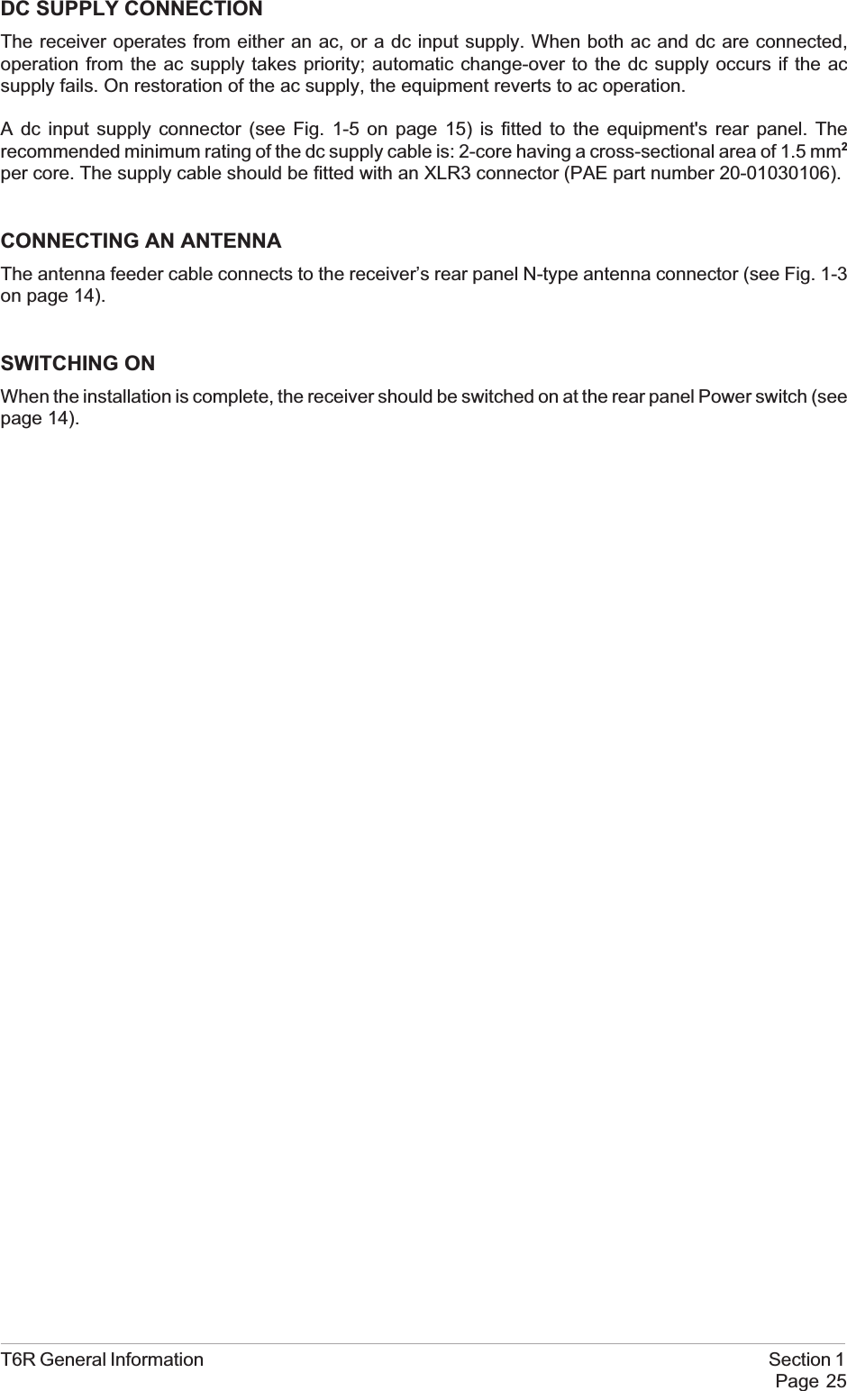
DC SUPPLY CONNECTIONThe receiver operates from either an ac, or a dc input supply. When both ac and dc are connected,operation from the ac supply takes priority; automatic change-over to the dc supply occurs if the acsupply fails. On restoration of the ac supply, the equipment reverts to ac operation.A dc input supply connector (see Fig. 1-5 on page 15) is fitted to the equipment's rear panel. Therecommended minimum rating of the dc supply cable is: 2-core having a cross-sectional area of 1.5 mm2per core. The supply cable should be fitted with an XLR3 connector (PAE part number 20-01030106).CONNECTING AN ANTENNAThe antenna feeder cable connects to the receiver’s rear panel N-type antenna connector (see Fig. 1-3on page 14).SWITCHING ONWhen the installation is complete, the receiver should be switched on at the rear panel Power switch (seepage 14).T6R General Information Section 1Page 25
Intentionally BlankSection 1 T6R General InformationPage 26
T6R Receiver User GuideSection 2AM-Voice ModeT6R AM-Voice Mode Section 2Page 1
Section 2 T6R AM-Voice ModePage 2PageSection 2 ContentsChapter 1. AM-Voice Mode OverviewIntroduction to AM-voice mode 3Operational Settings 3Basic Configuration 4Local Operation 4Remote Operation 4Configuration for Operation with MARC 6Chapter 2. SpecificationRF Characteristics 7Modulation Characteristics 7Chapter 3. InstallationIntroduction 9Connecting the Remote Facilities 10Connecting to MARC Equipment 10Chapter 4. Operational SettingsIntroduction 13Normal Operation 13Using the Scroll/Select Switch 13Screen Protocol 14Menu Lock Screen 16Notes for Setting Up the Receiver 17Front Panel Display for 25 kHz and 8.33 kHz Channel Spacing 17Line Level Setting 18To Enter and Exit Standby Mode 19To Enter Standby Mode 19To Exit Standby Mode 20AM-Voice Settings Procedure 21General Receiver Settings 25Selecting the Operating Frequency 29Allocating channel numbers to specified frequencies 30To Store Channel Frequencies 30To Recall Channel Frequencies 31To initiate an interruptive bit test 32To View BIT Pages and advise screen 33Elapsed time indicator 34displaying the receiver's internal reference frequency screen 35Software versions screen 36
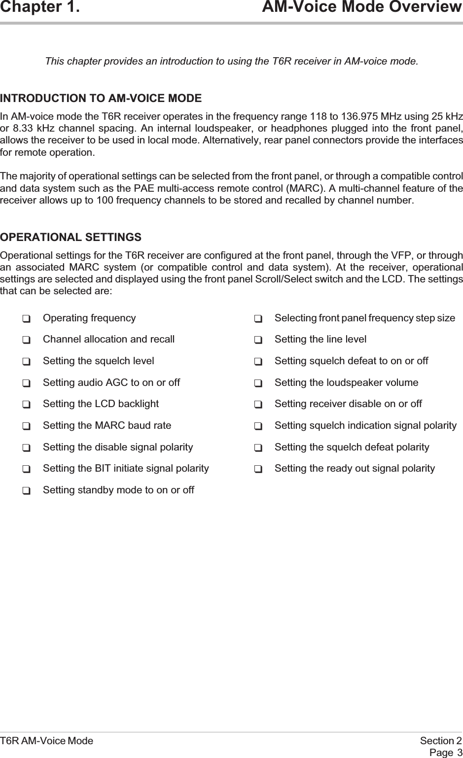
Chapter 1. AM-Voice Mode OverviewThis chapter provides an introduction to using the T6R receiver in AM-voice mode.INTRODUCTION TO AM-VOICE MODEIn AM-voice mode the T6R receiver operates in the frequency range 118 to 136.975 MHz using 25 kHzor 8.33 kHz channel spacing. An internal loudspeaker, or headphones plugged into the front panel,allows the receiver to be used in local mode. Alternatively, rear panel connectors provide the interfacesfor remote operation.The majority of operational settings can be selected from the front panel, or through a compatible controland data system such as the PAE multi-access remote control (MARC). A multi-channel feature of thereceiver allows up to 100 frequency channels to be stored and recalled by channel number.OPERATIONAL SETTINGSOperational settings for the T6R receiver are configured at the front panel, through the VFP, or throughan associated MARC system (or compatible control and data system). At the receiver, operationalsettings are selected and displayed using the front panel Scroll/Select switch and the LCD. The settingsthat can be selected are:qOperating frequency qSelecting front panel frequency step sizeqChannel allocation and recall qSetting the line levelqSetting the squelch level qSetting squelch defeat to on or offqSetting audio AGC to on or off qSetting the loudspeaker volumeqSetting the LCD backlight qSetting receiver disable on or offqSetting the MARC baud rate qSetting squelch indication signal polarityqSetting the disable signal polarity qSetting the squelch defeat polarityqSetting the BIT initiate signal polarity qSetting the ready out signal polarityqSetting standby mode to on or offT6R AM-Voice Mode Section 2Page 3
BASIC CONFIGURATIONFig. 2-1 shows the basic T6R receiver connections for AM-voice operation. If the receiver is part of aMARC system, or other compatible control and data system, refer to ‘Configuration for Operation withMARC’ on page 6.Local OperationIn its simplest configuration, the receiver can be operated in local mode. This involves using the built-inloudspeaker, or connecting a headset to the front panel Headset/Diagnostics connector. All operationalsettings are then selected using the Scroll/Select switch.Remote OperationFor remote operation signals are connected from the receiver's rear panel Facilities connector, through asuitable communication link, to the control equipment. Essential connections are the receiver's audiooutput and a squelch indication (a choice of squelch indication signals are available). Other remotesignals can be connected to suit the particular application. The remote signals are fully described insection 1 on page 17.In the basic configuration, the rear panel MARC and Computer Port connectors are not used. The frontpanel Reference connector is used to check the receiver's internal reference frequency duringscheduled maintenance. The front panel Headset/Diagnostics connector is used to connect a PC formaintenance purposes, or to use the VFP.Maintenance using a PC connected to the Headset/Diagnostics connector is outside the scope of thisuser guide. Full information is contained in the T6R maintenance handbook.Section 2 T6R AM-Voice ModePage 4
T6R AM-Voice Mode Section 2Page 5Fig. 2-1. T6R Receiver - Basic ConfigurationT6R ReceiverAntennaConnector FacilitiesConnectorHeadset for local operationPC for maintenancepurposesFrequency Counter formaintenance purposesAudioSquelch IndicationsUnregulated SupplyRSSIReady IndicationTape OutputSquelch Defeat SignalRx DisableBIT Interruptive TestRemote SignalsHeadset/DiagnosticsConnectorReferenceConnector
CONFIGURATION FOR OPERATION WITH MARCWhen the T6R receiver is used with a MARC system or other compatible control and data system, theremote signals are connected through the rear panel MARC connector (see Fig. 2-2). In thisconfiguration, the rear panel Facilities and Computer Port connectors are not used unless some auxiliarysignals available at the Facilities connector are required.Section 2 T6R AM-Voice ModePage 6T6R ReceiverFig. 2-2. T6R Receiver - Configuration for Use with MARCMARCConnectorHeadset/DiagnosticsConnectorReferenceConnectorAntennaConnectorAudioSquelch IndicationControl InformationStatus InformationUnregulated SupplyMARCRSE 2RSE 2has 8equipmentconnectorsallowing upto 8 radiosto beconnectedEquipmentConnectorHeadsetfor Engineering UsePC for maintenancepurposesFrequency Counter formaintenance purposes
Chapter 2. SpecificationThis chapter gives the receiver's specification applicable to AM-voice operation.RF CHARACTERISTICSChannel spacing 25 kHz, or 8.33 kHz across the frequency band 118 to136.975 MHz.Sensitivity Better than 1 µV PD (-107 dBm) for 10 dB (S+N)/N, or12 dB SINAD ratio; both with ITU-T recommendationP.53 weighting.IF selectivity For 25 kHz channel spacing:At ± 11 kHz from the centre frequency, the signal isnot attenuated by more than 6 dB.At ± 25 kHz from the centre frequency the signal isattenuated by more than 80 dB.For 8.33 kHz channel spacing:At ± 3.5 kHz from the centre frequency, the signal isnot attenuated by more than 6 dB.At ± 8.33 kHz from the centre frequency, the signalis attenuated by more than 70 dB.At ± 25 kHz from the centre frequency, the signal isattenuated by more than 80 dB.MODULATION CHARACTERISTICSFrequency response For 25 kHz channel spacing, the variation in frequencyresponse with reference to a 1 kHz signal, is within+2 dB, -3 dB across the frequency range 300 to3400 Hz. The response is better than -10 dB at 100 Hz,and better than -30 dB at 5 kHz.For 8.33 kHz channel spacing, the variation in frequencyresponse, with reference to a 1 kHz signal, is within+2 dB, -3 dB across the frequency range 350 to2500 Hz. The response is better than -10 dB at 100 Hz,and better than -30 dB at 5 kHz.Hum and noise With a -47 dBm RF input, the receiver's hum and noiseis more than 45 dB below the signal level for a carriermodulated by a 1 kHz signal with a modulation index of0.9.T6R AM-Voice Mode Section 2Page 7
Distortion For RF input signals between -47 dBm and +10 dBm,the total harmonic distortion is less than 5% due tosignals with a modulation index of 0.8 and within thefrequency range 300 Hz to 3400 Hz.AGC For received signals between -107 dBm and +10 dBmthere is less than 3 dB change in audio output. The AGCattack time is less than 15 ms and the decay time is lessthan 50 ms.Squelch The receiver has a noise compensated carrier operatedsquelch with an adjustment range of -114 to -60 dBm,and provides greater than 60 dB of quieting.Attack time is <50 ms for a signal rising 10 dB above thesquelch setting.Release time is <50 ms for a signal falling 10 dB belowthe squelch setting.Hysteresis 2 to 4 dB.Level control An audio AGC ensures there is less than 1 dB change inaudio output level when the modulation index isincreased from m = 0.3 to m = 0.9.The audio AGC can be switched off from the front panel,through MARC, or the VFP.Section 2 T6R AM-Voice ModePage 8
Chapter 3. InstallationThis chapter details the installation procedures that are applicable only to AM-voice operation.WARNING. LETHAL VOLTAGES!The instructions given in this chapter involve connecting lethal voltages to thereceiver. The instructions detailed in this chapter must be carried out only by suitablyqualified personnel.WARNING. UNAUTHORIZED MODIFICATIONS!Changes or modifications made to this equipment that are not expressly approved byPark Air Electronics, or parties authorized by Park Air Electronics, could void the user’sauthority to operate the equipment.CAUTION. ESSDs!The T6R receiver's circuitry contains Electrostatic Sensitive Devices (ESSDs).Personnel must be aware of the precautions necessary to prevent damage to suchdevices. During installation all precautions necessary to prevent ESSD damage must betaken.INTRODUCTIONThe procedures in this chapter that allow a T6R receiver to be installed for AM-voice operation are:qConnecting remote facilities in non-MARC applicationsqConnecting remote facilities to a MARC (or a compatible control and data system).T6R AM-Voice Mode Section 2Page 9
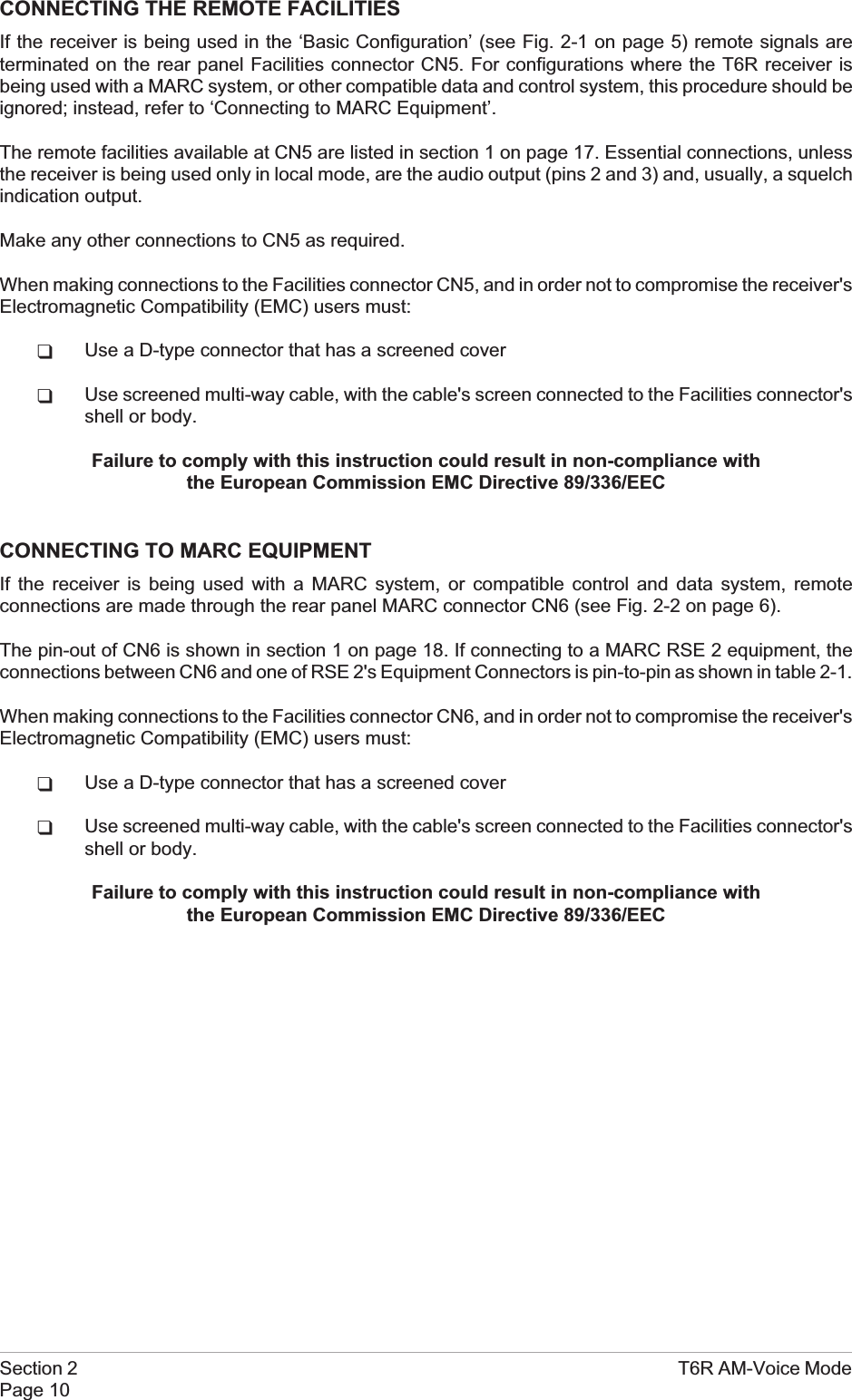
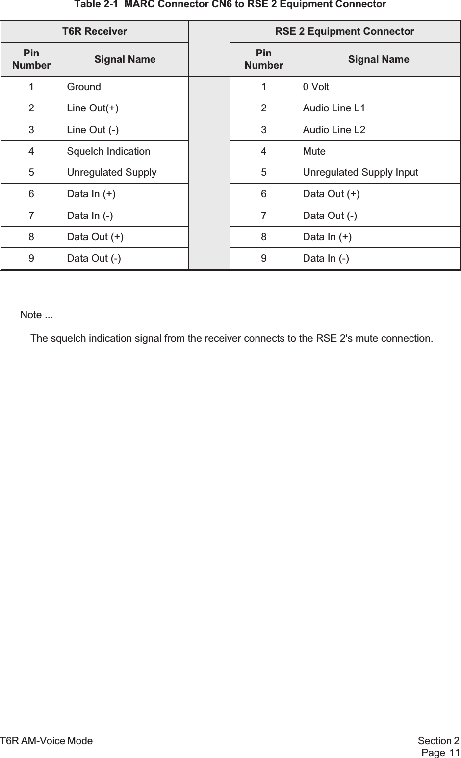
CONNECTING THE REMOTE FACILITIESIf the receiver is being used in the ‘Basic Configuration’ (see Fig. 2-1 on page 5) remote signals areterminated on the rear panel Facilities connector CN5. For configurations where the T6R receiver isbeing used with a MARC system, or other compatible data and control system, this procedure should beignored; instead, refer to ‘Connecting to MARC Equipment’.The remote facilities available at CN5 are listed in section 1 on page 17. Essential connections, unlessthe receiver is being used only in local mode, are the audio output (pins 2 and 3) and, usually, a squelchindication output.Make any other connections to CN5 as required.When making connections to the Facilities connector CN5, and in order not to compromise the receiver'sElectromagnetic Compatibility (EMC) users must:qUse a D-type connector that has a screened coverqUse screened multi-way cable, with the cable's screen connected to the Facilities connector'sshell or body.Failure to comply with this instruction could result in non-compliance withthe European Commission EMC Directive 89/336/EECCONNECTING TO MARC EQUIPMENTIf the receiver is being used with a MARC system, or compatible control and data system, remoteconnections are made through the rear panel MARC connector CN6 (see Fig. 2-2 on page 6).The pin-out of CN6 is shown in section 1 on page 18. If connecting to a MARC RSE 2 equipment, theconnections between CN6 and one of RSE 2's Equipment Connectors is pin-to-pin as shown in table 2-1.When making connections to the Facilities connector CN6, and in order not to compromise the receiver'sElectromagnetic Compatibility (EMC) users must:qUse a D-type connector that has a screened coverqUse screened multi-way cable, with the cable's screen connected to the Facilities connector'sshell or body.Failure to comply with this instruction could result in non-compliance withthe European Commission EMC Directive 89/336/EECSection 2 T6R AM-Voice ModePage 10
Table 2-1 MARC Connector CN6 to RSE 2 Equipment ConnectorT6R Receiver RSE 2 Equipment ConnectorPinNumber Signal Name PinNumber Signal Name1 Ground 1 0 Volt2 Line Out(+) 2 Audio Line L13 Line Out (-) 3 Audio Line L24 Squelch Indication 4 Mute5 Unregulated Supply 5 Unregulated Supply Input6 Data In (+) 6 Data Out (+)7 Data In (-) 7 Data Out (-)8 Data Out (+) 8 Data In (+)9 Data Out (-) 9 Data In (-)Note ...The squelch indication signal from the receiver connects to the RSE 2's mute connection.T6R AM-Voice Mode Section 2Page 11
Intentionally BlankSection 2 T6R AM-Voice ModePage 12
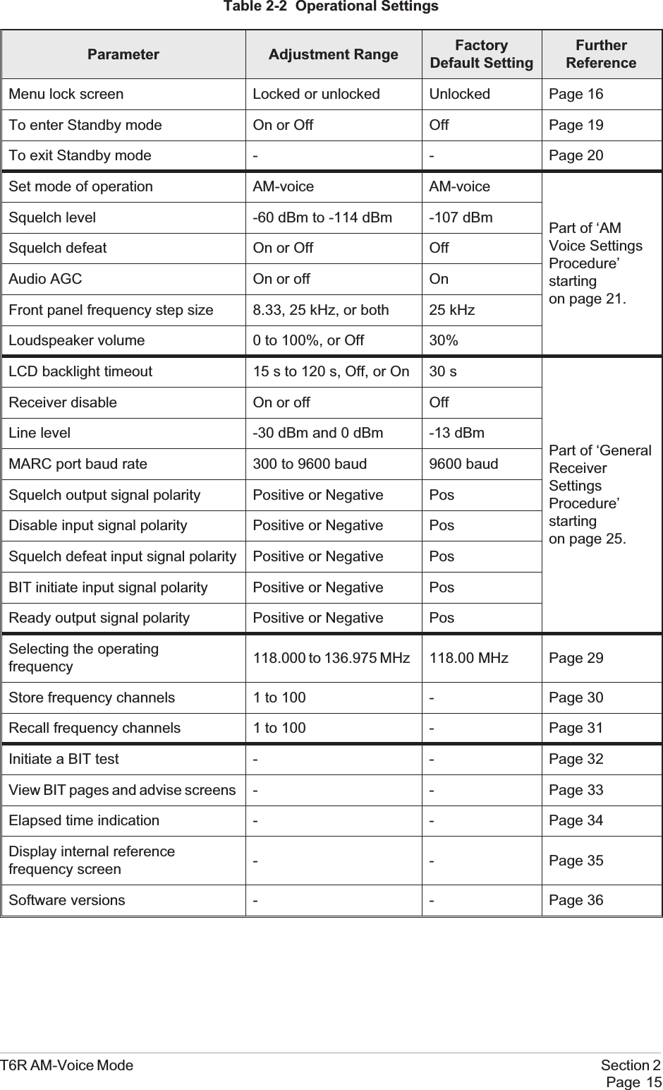
Chapter 4. Operational SettingsThis chapter details how the T6R receiver is set up for AM-Voice operation from the front panel.It also details how to set the receiver in and out of standby mode.The receiver can also be set up through a MARC system, or by using the VFP. Both ofthese methods are outside the scope of this handbook; users should refer to the MARCUser Guide and the T6R Maintenance Handbook.INTRODUCTIONSelecting most of the receiver's operational settings is carried out using the front panel Scroll/Selectswitch and the LCD (see the illustration below). Table 2-2 on page 15 shows a list of the operationalsettings. No attempt to set up the receiver should be made until it has been installed as per theInstallation Procedures given in section 1 of this user guide.Normal OperationDuring normal operation, the LCD displays the Main screen. This screen shows the operating frequency,the channel number (if the channel store facility is used) and displays a graphical representation ofvolume. The receiver's loudspeaker and headset volume can be adjusted by rotating the Scroll/Selectswitch. If the receiver has been set to Standby mode, which is shown by the front panel STANDBYindicator being lit, the LCD is blanked.Using the Scroll/Select SwitchThe SCROLL/SELECT switch (referred to throughout this chapter as the ‘Switch’) is used to exit theMain screen and display the Options menu. Further use of the Switch displays various selection menusand allows the required parameters to be set. The switch has three actions: it can be turned clockwise,anti-clockwise, or momentarily pushed in.Note that during normal receiver operation, the Scroll/Select switch acts as a volume control.T6R AM-Voice Mode Section 2Page 13Freq 123.000MHzChan 1Vol llllllllllll
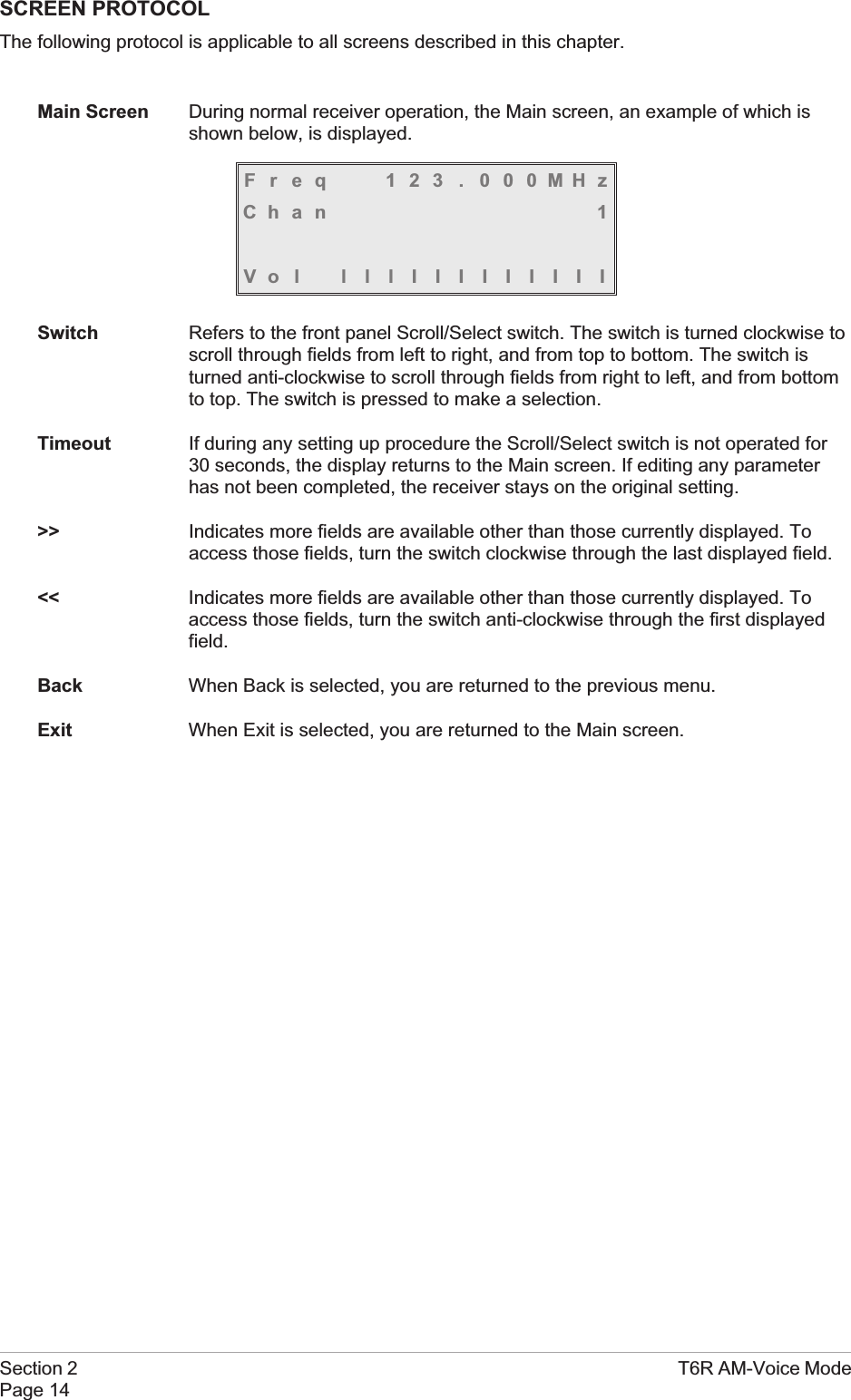
SCREEN PROTOCOLThe following protocol is applicable to all screens described in this chapter.Main Screen During normal receiver operation, the Main screen, an example of which isshown below, is displayed.Freq 123 . 000MHzChan 1Vol lllIIIIIIIIISwitch Refers to the front panel Scroll/Select switch. The switch is turned clockwise toscroll through fields from left to right, and from top to bottom. The switch isturned anti-clockwise to scroll through fields from right to left, and from bottomto top. The switch is pressed to make a selection.Timeout If during any setting up procedure the Scroll/Select switch is not operated for30 seconds, the display returns to the Main screen. If editing any parameterhas not been completed, the receiver stays on the original setting.>> Indicates more fields are available other than those currently displayed. Toaccess those fields, turn the switch clockwise through the last displayed field.<< Indicates more fields are available other than those currently displayed. Toaccess those fields, turn the switch anti-clockwise through the first displayedfield.Back When Back is selected, you are returned to the previous menu.Exit When Exit is selected, you are returned to the Main screen.Section 2 T6R AM-Voice ModePage 14
Table 2-2 Operational SettingsParameter Adjustment Range FactoryDefault SettingFurtherReferenceMenu lock screen Locked or unlocked Unlocked Page 16To enter Standby mode On or Off Off Page 19To exit Standby mode - - Page 20Set mode of operation AM-voice AM-voicePart of ‘AMVoice SettingsProcedure’startingon page 21.Squelch level -60 dBm to -114 dBm -107 dBmSquelch defeat On or Off OffAudio AGC On or off OnFront panel frequency step size 8.33, 25 kHz, or both 25 kHzLoudspeaker volume 0 to 100%, or Off 30%LCD backlight timeout 15 s to 120 s, Off, or On 30 sPart of ‘GeneralReceiverSettingsProcedure’startingon page 25.Receiver disable On or off OffLine level -30 dBm and 0 dBm -13 dBmMARC port baud rate 300 to 9600 baud 9600 baudSquelch output signal polarity Positive or Negative PosDisable input signal polarity Positive or Negative PosSquelch defeat input signal polarity Positive or Negative PosBIT initiate input signal polarity Positive or Negative PosReady output signal polarity Positive or Negative PosSelecting the operatingfrequency 118.000 to 136.975 MHz 118.00 MHz Page 29Store frequency channels 1 to 100 - Page 30Recall frequency channels 1 to 100 - Page 31Initiate a BIT test - - Page 32View BIT pages and advise screens - - Page 33Elapsed time indication - - Page 34Display internal referencefrequency screen - - Page 35Software versions - - Page 36T6R AM-Voice Mode Section 2Page 15
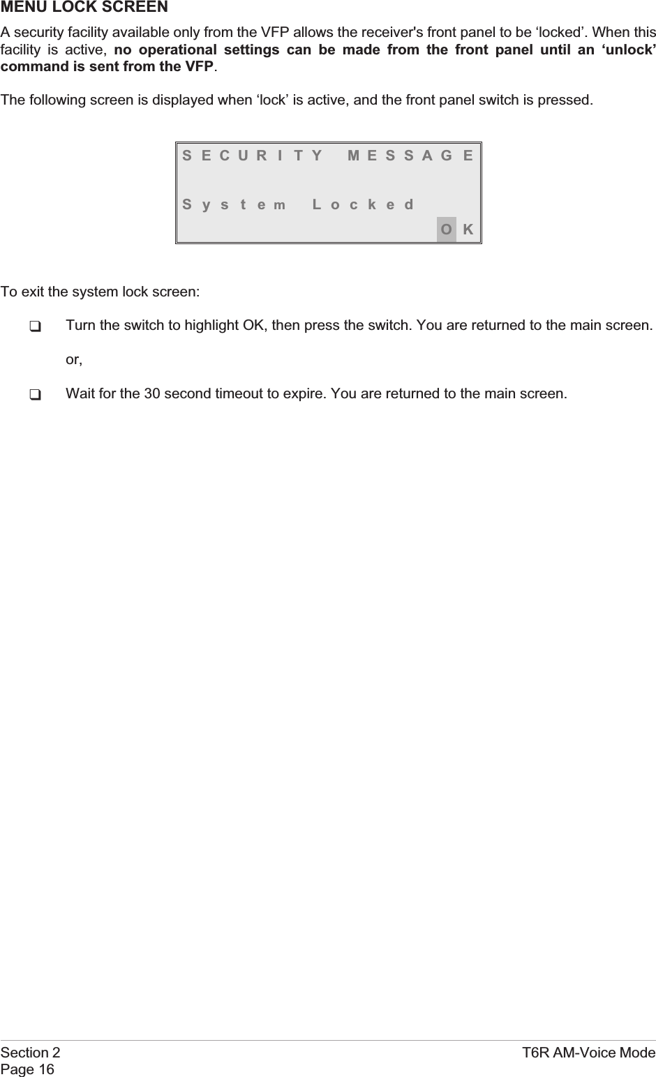
MENU LOCK SCREENA security facility available only from the VFP allows the receiver's front panel to be ‘locked’. When thisfacility is active, no operational settings can be made from the front panel until an ‘unlock’command is sent from the VFP.The following screen is displayed when ‘lock’ is active, and the front panel switch is pressed.S ECUR I TY MESSAG ESystemLockedOKTo exit the system lock screen:qTurn the switch to highlight OK, then press the switch. You are returned to the main screen.or,qWait for the 30 second timeout to expire. You are returned to the main screen.Section 2 T6R AM-Voice ModePage 16
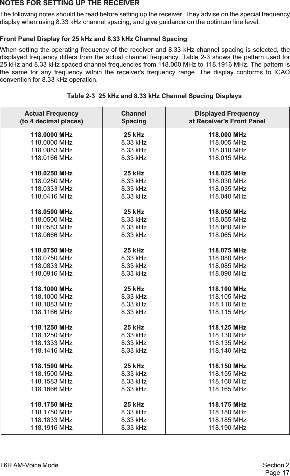
NOTES FOR SETTING UP THE RECEIVERThe following notes should be read before setting up the receiver. They advise on the special frequencydisplay when using 8.33 kHz channel spacing, and give guidance on the optimum line level.Front Panel Display for 25 kHz and 8.33 kHz Channel SpacingWhen setting the operating frequency of the receiver and 8.33 kHz channel spacing is selected, thedisplayed frequency differs from the actual channel frequency. Table 2-3 shows the pattern used for25 kHz and 8.33 kHz spaced channel frequencies from 118.000 MHz to 118.1916 MHz. The pattern isthe same for any frequency within the receiver's frequency range. The display conforms to ICAOconvention for 8.33 kHz operation.Table 2-3 25 kHz and 8.33 kHz Channel Spacing DisplaysActual Frequency(to 4 decimal places)ChannelSpacingDisplayed Frequencyat Receiver's Front Panel118.0000 MHz118.0000 MHz118.0083 MHz118.0166 MHz118.0250 MHz118.0250 MHz118.0333 MHz118.0416 MHz118.0500 MHz118.0500 MHz118.0583 MHz118.0666 MHz118.0750 MHz118.0750 MHz118.0833 MHz118.0916 MHz118.1000 MHz118.1000 MHz118.1083 MHz118.1166 MHz118.1250 MHz118.1250 MHz118.1333 MHz118.1416 MHz118.1500 MHz118.1500 MHz118.1583 MHz118.1666 MHz118.1750 MHz118.1750 MHz118.1833 MHz118.1916 MHz25 kHz8.33 kHz8.33 kHz8.33 kHz25 kHz8.33 kHz8.33 kHz8.33 kHz25 kHz8.33 kHz8.33 kHz8.33 kHz25 kHz8.33 kHz8.33 kHz8.33 kHz25 kHz8.33 kHz8.33 kHz8.33 kHz25 kHz8.33 kHz8.33 kHz8.33 kHz25 kHz8.33 kHz8.33 kHz8.33 kHz25 kHz8.33 kHz8.33 kHz8.33 kHz118.000 MHz118.005 MHz118.010 MHz118.015 MHz118.025 MHz118.030 MHz118.035 MHz118.040 MHz118.050 MHz118.055 MHz118.060 MHz118.065 MHz118.075 MHz118.080 MHz118.085 MHz118.090 MHz118.100 MHz118.105 MHz118.110 MHz118.115 MHz118.125 MHz118.130 MHz118.135 MHz118.140 MHz118.150 MHz118.155 MHz118.160 MHz118.165 MHz118.175 MHz118.180 MHz118.185 MHz118.190 MHzT6R AM-Voice Mode Section 2Page 17
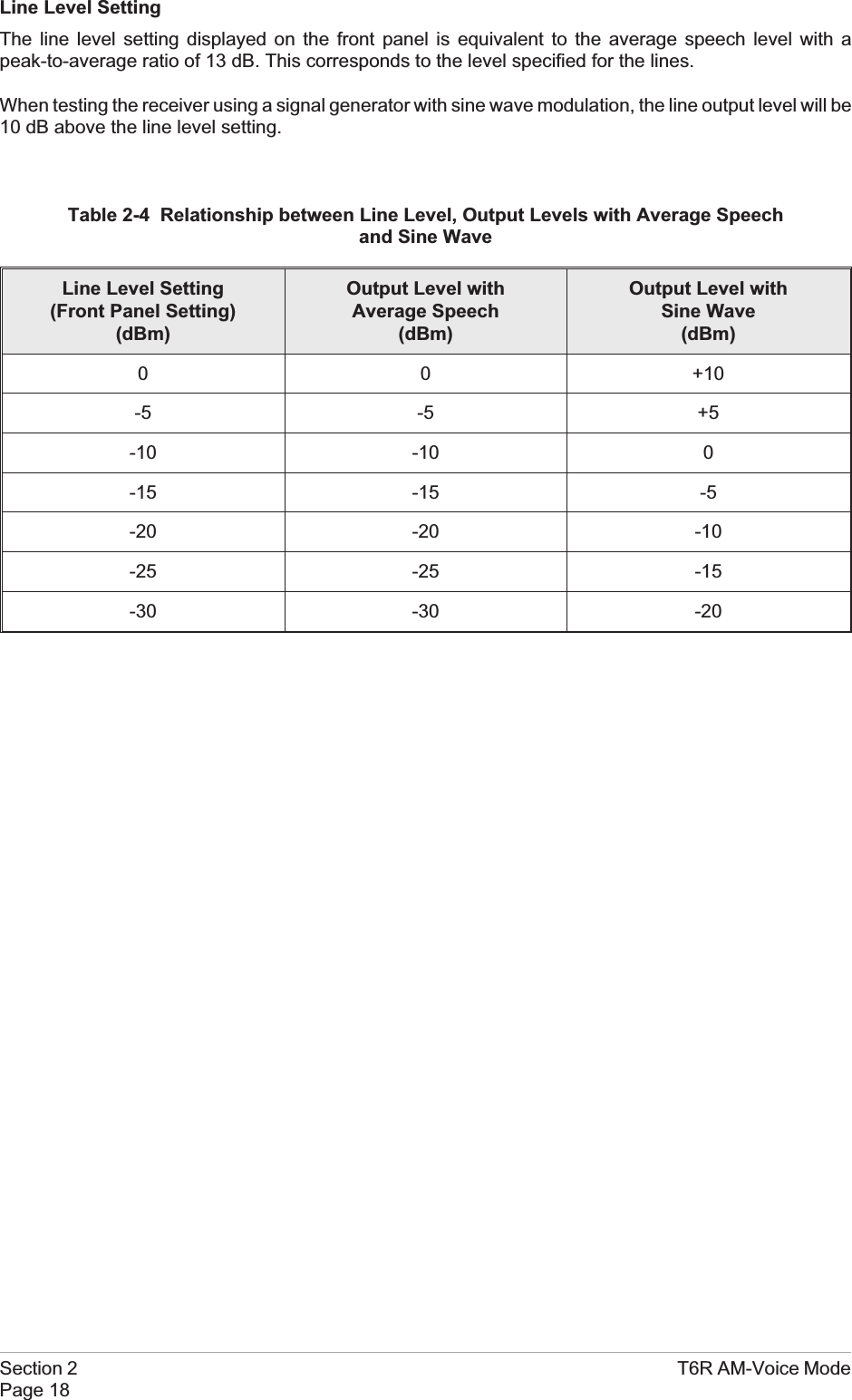
Line Level SettingThe line level setting displayed on the front panel is equivalent to the average speech level with apeak-to-average ratio of 13 dB. This corresponds to the level specified for the lines.When testing the receiver using a signal generator with sine wave modulation, the line output level will be10 dB above the line level setting.Table 2-4 Relationship between Line Level, Output Levels with Average Speechand Sine WaveLine Level Setting(Front Panel Setting)(dBm)Output Level withAverage Speech(dBm)Output Level withSine Wave(dBm)0 0 +10-5 -5 +5-10 -10 0-15 -15 -5-20 -20 -10-25 -25 -15-30 -30 -20Section 2 T6R AM-Voice ModePage 18
TO ENTER AND EXIT STANDBY MODEStandby mode is a power saving feature that can be used for non-operational receivers. When instandby mode, most of the receiver's circuits are inactive, the LCD is blanked, and there is no audiooutput.To Enter Standby ModeTo put the receiver into standby mode, use the following procedure.1. From the Main screen, press the switch todisplay the Options menu. Ensure thatConfigure is highlighted. Press the switch.2. Ensure the Configure menu is displayed.Turn the switch until Standby is highlighted,then press the switch.3. Check that the Standby menu is displayed.Turn the switch until Yes is highlighted, thenpress the switch. [To abandon thisprocedure, select No instead of Yes andthen press the switch.]4. Check that the LCD blanks, and the front panel STANDBY indicator lights.5. The receiver is now in standby mode. To exit standby, see the next procedure.T6R AM-Voice Mode Section 2Page 19FrequencyChanne lCon f i gu r eBIT Exi tSe t t i ngsS/W VersionsSt andbyBack Ex i tPut radio intoSt andby mode ?YES NO
To Exit Standby ModeStandby mode is indicated by the front panel STANDBY indicator being lit and the LCD being blanked.To exit this mode, use the following procedure.1. Press the switch and check that the Exitmenu is displayed.2. Turn the switch until YES is highlighted,then press the switch. [To abandon thisprocedure, select No instead of Yes andthen press the switch.]3. Check that the Main screen is displayed and that the front panel STANDBY indicator is unlit.4. The receiver is now ready for normal use.Section 2 T6R AM-Voice ModePage 20Ex i t St andbyMod eYES NOFreq 123 . 000MHzVo l llllllllllll
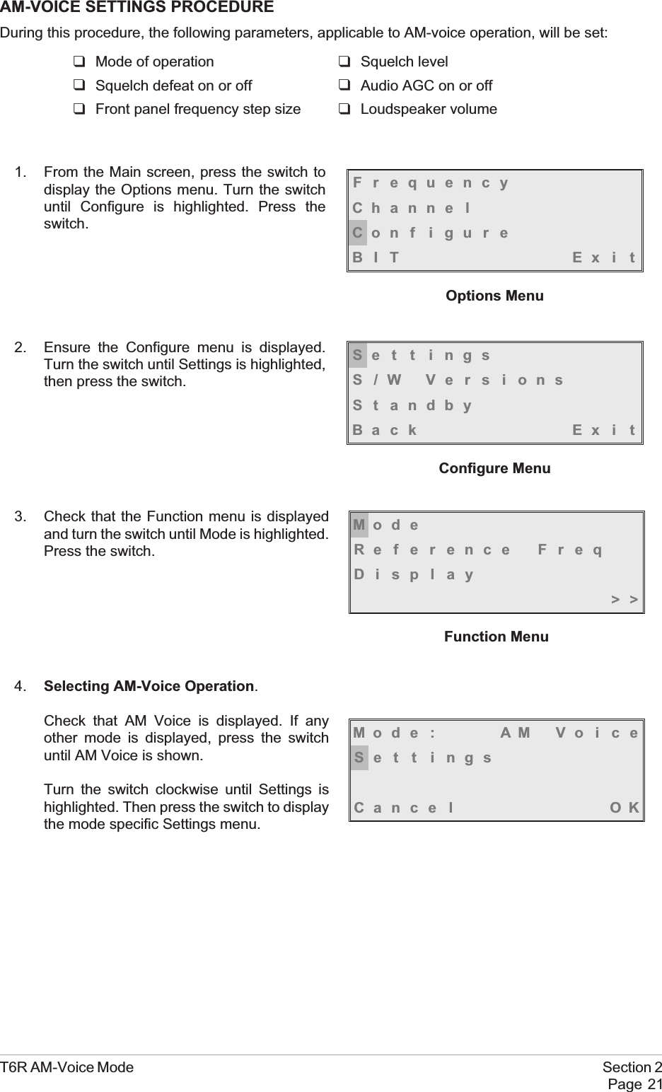
AM-VOICE SETTINGS PROCEDUREDuring this procedure, the following parameters, applicable to AM-voice operation, will be set:qMode of operation qSquelch levelqSquelch defeat on or off qAudio AGC on or offqFront panel frequency step size qLoudspeaker volume1. From the Main screen, press the switch todisplay the Options menu. Turn the switchuntil Configure is highlighted. Press theswitch.2. Ensure the Configure menu is displayed.Turn the switch until Settings is highlighted,then press the switch.3. Check that the Function menu is displayedand turn the switch until Mode is highlighted.Press the switch.4. Selecting AM-Voice Operation.Check that AM Voice is displayed. If anyother mode is displayed, press the switchuntil AM Voice is shown.Turn the switch clockwise until Settings ishighlighted. Then press the switch to displaythe mode specific Settings menu.T6R AM-Voice Mode Section 2Page 21FrequencyChanne lCon f i gu r eBIT Exi tOptions MenuMod eReference FreqDisplay>>Function MenuSe t t i ngsS/W VersionsSt andbyBack Ex i tConfigure MenuMod e : AM Vo i c eSe t t i ngsCance l OK
5. Setting the Squelch Level.[Factory default setting: -107 dBm]The receiver's squelch level can be setbetween -60 dBm and -114 dBm.To set the squelch level, ensure Squelch ishighlighted. Press the switch. Turn the switchclockwise or anti-clockwise to increase ordecrease the value. When the required valueis displayed, press the switch. Turn the switchclockwise to highlight Sql Defeat.6. Setting Squelch Defeat to On or Off.[Factory default setting: Off]The receiver's squelch facility can be switched on or off.Ensure that Sql Defeat is highlighted. Pressthe switch to toggle between On and Off.On = Squelch Defeated. The receiver'ssquelch circuit does not operate and the frontpanel Receive indicator stays lit.Off = Squelch facility enabled. An audio outputis heard only when a signal greater than the squelch level is received.When the required setting is highlighted, turn the switch clockwise to highlight Audio AGC.7. Setting the Audio AGC.[Factory default setting: On]The receiver's Audio AGC facility can beswitched On or Off.When set to on, the audio output level remainsconstant for received signal modulation depthsgreater than 30%.When set to off, the audio output level isproportional to the received signal modulationdepth.To make the required setting, ensure Audio AGC is highlighted. Press the switch to togglebetween On and Off.When the required setting is highlighted, turn the switch clockwise to highlight Channel Spacing.Section 2 T6R AM-Voice ModePage 22Squelch -107dBmSql Defeat OFFAu d i o AGC ON>>Mode Specific Settings MenuSquelch -107dBmSql Defeat OFFAu d i o AGC ON>>Squelch -107dBmSql Defeat OFFAu d i o AGC ON>>
8. Setting the Front Panel Frequency Step Size.[Factory default setting: 25 kHz]The receiver's channel spacing can be 25 kHz, or 8.33 kHz. The radio automatically sets thecorrect channel spacing for the frequency that is entered at the front panel. This setting, which isonly for the user's convenience, alters front panel frequency step size.qIf all channels to be selected or stored are 25 kHz spaced channels, then 25 should beselected.qIf all channels to be selected or stored are 8.33 kHz spaced channels, then 8.3 should beselected.qIf a mixture of the two are required, both 25 and 8.3 should be selected.To select the required spacing, ensure thatChannel Spacing is highlighted and press theswitch.Check that the Channel Spacing menu isdisplayed and that Spacing is highlighted.Press the switch to change between 25 kHz,8.3 kHz, and both. When the required value isdisplayed, turn the switch to highlight OK, thenpress the switch again. You will be returned tothe Mode Specific Settings menu.T6R AM-Voice Mode Section 2Page 23Channe l Spac i ngLoudspeakerBackEx i t <<Spac ing 25kHz8.3kHzCance l OKChannel Spacing Menu (Both Selected)
9. Setting the Loudspeaker/Headset Volume.[Factory default setting: 30% Volume; Loudspeaker On]The receiver's loudspeaker and headset volume can be set, and the speaker can be switched onor off during this procedure.Turn the switch clockwise until Loudspeaker is highlighted, then press the switch.Ensure that the Loudspeaker menu isdisplayed and that Volume is highlighted.Press the switch. Turn the switch clockwise toincrease volume, or anti-clockwise todecrease volume. When the required value(0 to 100%) is displayed, press the switch.Turnthe switch clockwise until OK is highlighted,then press the switch.To turn the loudspeaker on and off, highlightSpeaker and press the switch to togglebetween On and Off. When the requiredsetting is displayed, turn the switch to highlightOK, then press the switch. You are returned tothe Mode Specific Settings menu.10. To exit the AM-Voice Settings Procedure, turn the switch to highlight Exit, then press the switch.You are returned to the Main screen. When this procedure is complete, go to the GeneralReceiver Settings procedure starting on the next page.Section 2 T6R AM-Voice ModePage 24Volume 030%Speaker ONOKChanne l Spac i ngLoudspeakerBackEx i t <<
GENERAL RECEIVER SETTINGSDuring this procedure, the following parameters will be set:qLCD backlight qDisable on or offqLine level qMARC baud rateqSquelch output signal polarity qDisable input signal polarityqSquelch defeat polarity qBIT initiate signal polarityqReady output signal polarity1. From the Main screen, press the switch todisplay the Options menu. Turn the switchuntil Configure is highlighted. Press theswitch.2. Ensure the Configure menu is displayed.Turn the switch until Settings is highlighted,then press the switch.3. Setting the LCD Backlight.[Factory default setting: 30 s]Check that the Settings menu is displayedand turn the switch until Display ishighlighted. Press the switch.The LCD's backlight can be set to off,permanently on, or timed to stay on for aperiod between 15 and 120 seconds(adjustable in 15 second steps) after theScroll/Select switch was last operated.Ensure the Backlight menu is displayed andBacklight is highlighted. Press the switch.Turn the switch until the required setting isdisplayed, then press the switch. Turn theswitch clockwise until OK is highlighted, thenpress the switch. You are returned to theSettings menu.T6R AM-Voice Mode Section 2Page 25FrequencyChanne lCon f i gu r eBIT Exi tOptions MenuSe t t i ngsS/W VersionsSt andbyBack Ex i tConfigure MenuMod eReference FreqDisplay>>Settings MenuBack l i ght 030sCance l OK
4. Setting Disable On or Off.[Factory default setting: Off]Receiver disable can be set to either On or Off. When set to on, the receiver's audio output isdisabled. When set to off, audio is available through the internal loudspeaker, the headset, orthrough the remote audio lines.From the Settings menu, turn the switchclockwise until Disable is highlighted, thenpress the switch.Check that the Disable menu is displayed andDisable is highlighted. Pressing the switchtoggles between On and Off. When the correctsetting is displayed turn the switch clockwiseto highlight OK, then press the switch. You arereturned to the Settings menu.5. Setting the Line Level.[Factory default setting: -13 dBm]The audio line output level can be set to any value between -30 dBm and 0 dBm. Some notesregarding the optimum line level are given on page 18.From the Settings menu, turn the switchclockwise until Line Level is highlighted, thenpress the switch.Check that the Line Level menu is displayedand that Line Lvl is highlighted, then press theswitch.Turn the switch clockwise or anti-clockwise toincrease or decrease the value. When therequired value is displayed, press the switch.Turn the switch to highlight OK and then pressthe switch. You are returned to the Settings menu.Section 2 T6R AM-Voice ModePage 26DisableLine LevelMARC<< >>Disable ONCance l OKDisableLine LevelMARC<< >>Line Lvl -13dBmCance l OK
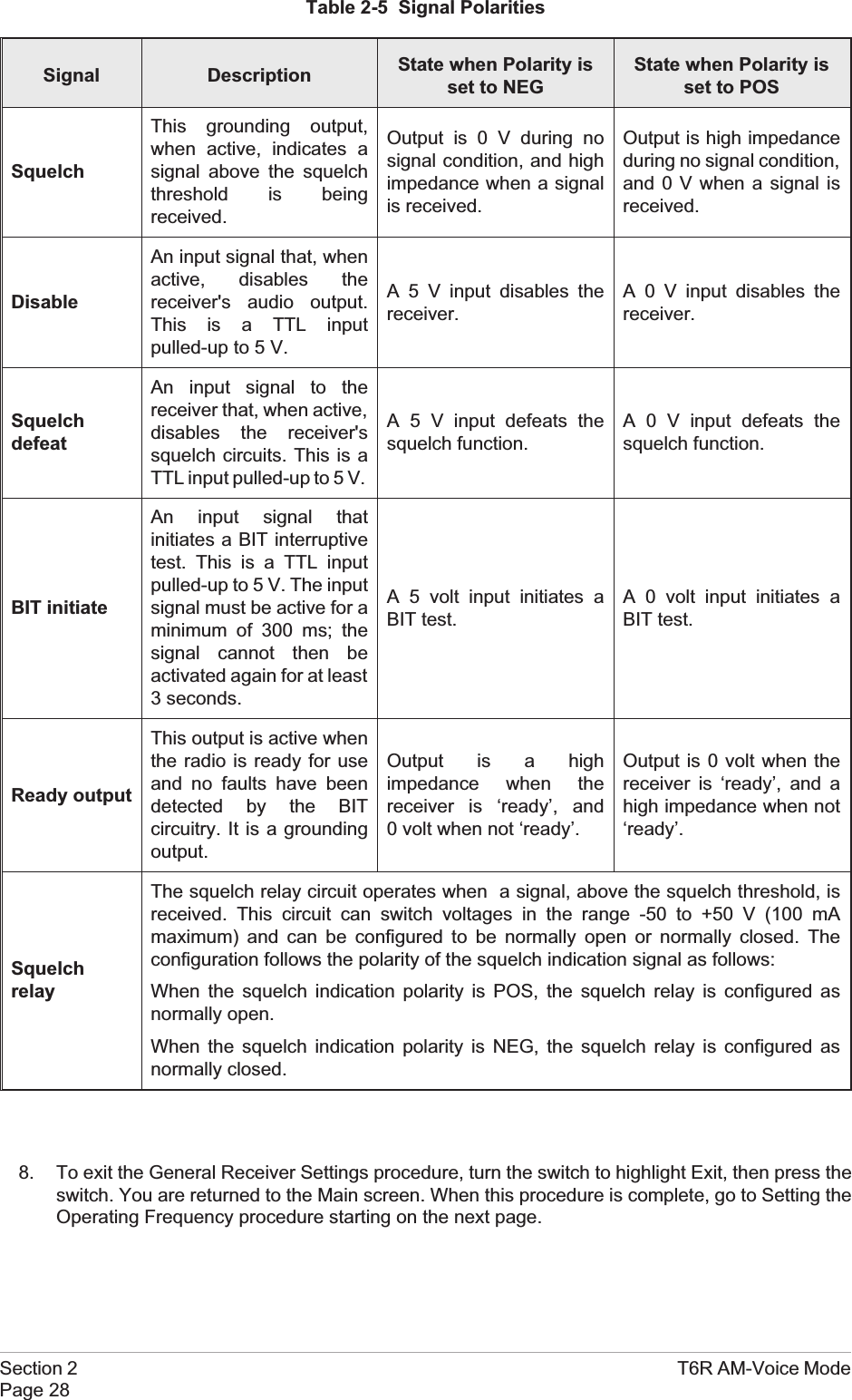
6. Setting the MARC Baud Rate.[Factory default setting: 9600]The baud rate must be set when the T6R receiver is connected to a MARC system (or othercompatible data and control system). The rate can be set to 300, 600, 1200, 2400, 4800, or 9600baud.From the Settings menu, turn the switchclockwise until MARC is highlighted, thenpress the switch.Ensure that the MARC menu is displayedand that Baud Rate is highlighted.Press the switch. Turn the switch until therequired value is displayed, then press theswitch. Turn the switch clockwise until OK ishighlighted, then press the switch. You arereturned to the Settings menu.7. Polarity Settings.The polarity of the following input and output signals is set using the Polarity menu:qSquelch output signalqDisable input signalqSquelch defeat input signalqBIT initiate input signalqReady output signal.To establish the required polarity for the input and output signals, refer to table 2-5.From the Settings menu, turn the switch untilPolarity is highlighted. Then press the switchto display the Polarity menu.To set the required polarity, turn the switch tohighlight the required parameter, then pressthe switch to toggle between NEG and POS.When all polarities have been set, highlightBack, and press the switch to return to theSettings menu.T6R AM-Voice Mode Section 2Page 27Baud Rate 9600Cance l OKDisableLine LevelMARC<< >>Disable NEGSquelch Out POSSquelch Def NEG>>BIT Ini t NEGReady Out POSBackEx i t <<Polarity MenuPolarityBackEx i t<<
Table 2-5 Signal PolaritiesSignal Description State when Polarity isset to NEGState when Polarity isset to POSSquelchThis grounding output,when active, indicates asignal above the squelchthreshold is beingreceived.Output is 0 V during nosignal condition, and highimpedance when a signalis received.Output is high impedanceduring no signal condition,and 0 V when a signal isreceived.DisableAn input signal that, whenactive, disables thereceiver's audio output.This is a TTL inputpulled-up to 5 V.A 5 V input disables thereceiver.A 0 V input disables thereceiver.SquelchdefeatAn input signal to thereceiver that, when active,disables the receiver'ssquelch circuits. This is aTTL input pulled-up to 5 V.A 5 V input defeats thesquelch function.A 0 V input defeats thesquelch function.BIT initiateAn input signal thatinitiates a BIT interruptivetest. This is a TTL inputpulled-up to 5 V. The inputsignal must be active for aminimum of 300 ms; thesignal cannot then beactivated again for at least3 seconds.A 5 volt input initiates aBIT test.A 0 volt input initiates aBIT test.Ready outputThis output is active whenthe radio is ready for useand no faults have beendetected by the BITcircuitry. It is a groundingoutput.Output is a highimpedance when thereceiver is ‘ready’, and0 volt when not ‘ready’.Output is 0 volt when thereceiver is ‘ready’, and ahigh impedance when not‘ready’.SquelchrelayThe squelch relay circuit operates when a signal, above the squelch threshold, isreceived. This circuit can switch voltages in the range -50 to +50 V (100 mAmaximum) and can be configured to be normally open or normally closed. Theconfiguration follows the polarity of the squelch indication signal as follows:When the squelch indication polarity is POS, the squelch relay is configured asnormally open.When the squelch indication polarity is NEG, the squelch relay is configured asnormally closed.8. To exit the General Receiver Settings procedure, turn the switch to highlight Exit, then press theswitch. You are returned to the Main screen. When this procedure is complete, go to Setting theOperating Frequency procedure starting on the next page.Section 2 T6R AM-Voice ModePage 28
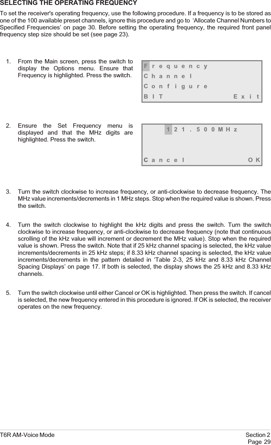
SELECTING THE OPERATING FREQUENCYTo set the receiver's operating frequency, use the following procedure. If a frequency is to be stored asone of the 100 available preset channels, ignore this procedure and go to ‘Allocate Channel Numbers toSpecified Frequencies’ on page 30. Before setting the operating frequency, the required front panelfrequency step size should be set (see page 23).1. From the Main screen, press the switch todisplay the Options menu. Ensure thatFrequency is highlighted. Press the switch.2. Ensure the Set Frequency menu isdisplayed and that the MHz digits arehighlighted. Press the switch.3. Turn the switch clockwise to increase frequency, or anti-clockwise to decrease frequency. TheMHz value increments/decrements in 1 MHz steps. Stop when the required value is shown. Pressthe switch.4. Turn the switch clockwise to highlight the kHz digits and press the switch. Turn the switchclockwise to increase frequency, or anti-clockwise to decrease frequency (note that continuousscrolling of the kHz value will increment or decrement the MHz value). Stop when the requiredvalue is shown. Press the switch. Note that if 25 kHz channel spacing is selected, the kHz valueincrements/decrements in 25 kHz steps; if 8.33 kHz channel spacing is selected, the kHz valueincrements/decrements in the pattern detailed in ‘Table 2-3, 25 kHz and 8.33 kHz ChannelSpacing Displays’ on page 17. If both is selected, the display shows the 25 kHz and 8.33 kHzchannels.5. Turn the switch clockwise until either Cancel or OK is highlighted. Then press the switch. If cancelis selected, the new frequency entered in this procedure is ignored. If OK is selected, the receiveroperates on the new frequency.T6R AM-Voice Mode Section 2Page 29FrequencyChanne lCon f i gu r eBIT Exi t121 . 500MHzCance l OK
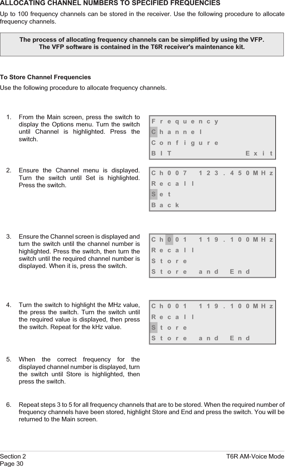
ALLOCATING CHANNEL NUMBERS TO SPECIFIED FREQUENCIESUp to 100 frequency channels can be stored in the receiver. Use the following procedure to allocatefrequency channels.To Store Channel FrequenciesUse the following procedure to allocate frequency channels.1. From the Main screen, press the switch todisplay the Options menu. Turn the switchuntil Channel is highlighted. Press theswitch.2. Ensure the Channel menu is displayed.Turn the switch until Set is highlighted.Press the switch.3. Ensure the Channel screen is displayed andturn the switch until the channel number ishighlighted. Press the switch, then turn theswitch until the required channel number isdisplayed. When it is, press the switch.4. Turn the switch to highlight the MHz value,the press the switch. Turn the switch untilthe required value is displayed, then pressthe switch. Repeat for the kHz value.5. When the correct frequency for thedisplayed channel number is displayed, turnthe switch until Store is highlighted, thenpress the switch.6. Repeat steps 3 to 5 for all frequency channels that are to be stored. When the required number offrequency channels have been stored, highlight Store and End and press the switch. You will bereturned to the Main screen.Section 2 T6R AM-Voice ModePage 30The process of allocating frequency channels can be simplified by using the VFP.The VFP software is contained in the T6R receiver's maintenance kit.FrequencyChanne lCon f i gu r eBIT Exi tCh007 123 . 450MHzReca l lSe tBackCh001 119 . 100MHzReca l lStoreStore and EndCh001 119 . 100MHzReca l lStoreStore and End
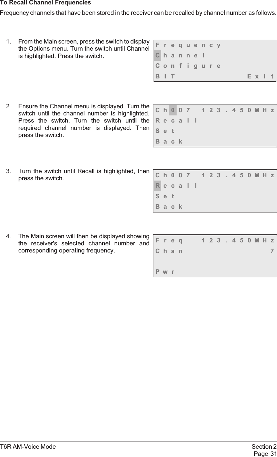
To Recall Channel FrequenciesFrequency channels that have been stored in the receiver can be recalled by channel number as follows.1. From the Main screen, press the switch to displaythe Options menu. Turn the switch until Channelis highlighted. Press the switch.2. Ensure the Channel menu is displayed. Turn theswitch until the channel number is highlighted.Press the switch. Turn the switch until therequired channel number is displayed. Thenpress the switch.3. Turn the switch until Recall is highlighted, thenpress the switch.4. The Main screen will then be displayed showingthe receiver's selected channel number andcorresponding operating frequency.T6R AM-Voice Mode Section 2Page 31FrequencyChanne lCon f i gu r eBIT Exi tCh007 123 . 450MHzReca l lSe tBackCh007 123 . 450MHzReca l lSe tBackFreq 123 . 450MHzChan 7Pw r
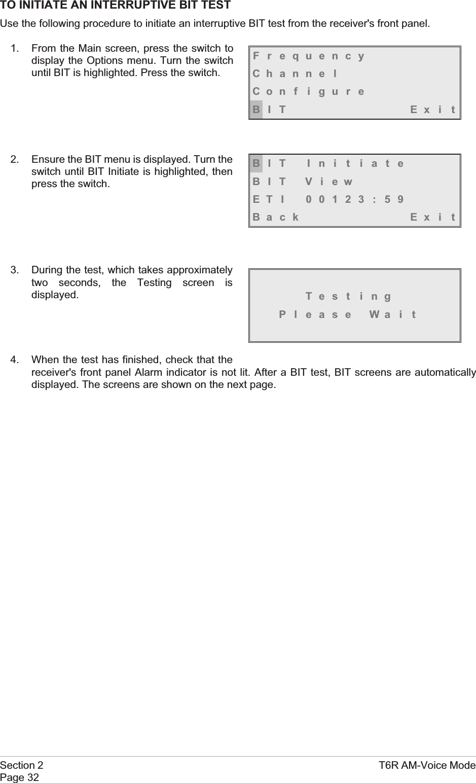
TO INITIATE AN INTERRUPTIVE BIT TESTUse the following procedure to initiate an interruptive BIT test from the receiver's front panel.1. From the Main screen, press the switch todisplay the Options menu. Turn the switchuntil BIT is highlighted. Press the switch.2. Ensure the BIT menu is displayed. Turn theswitch until BIT Initiate is highlighted, thenpress the switch.3. During the test, which takes approximatelytwo seconds, the Testing screen isdisplayed.4. When the test has finished, check that thereceiver's front panel Alarm indicator is not lit. After a BIT test, BIT screens are automaticallydisplayed. The screens are shown on the next page.Section 2 T6R AM-Voice ModePage 32FrequencyChanne lCon f i gu r eBIT Exi tBIT Ini t iateBIT ViewETI 00123:59Back Ex i tTest ingPl ease Wa i t
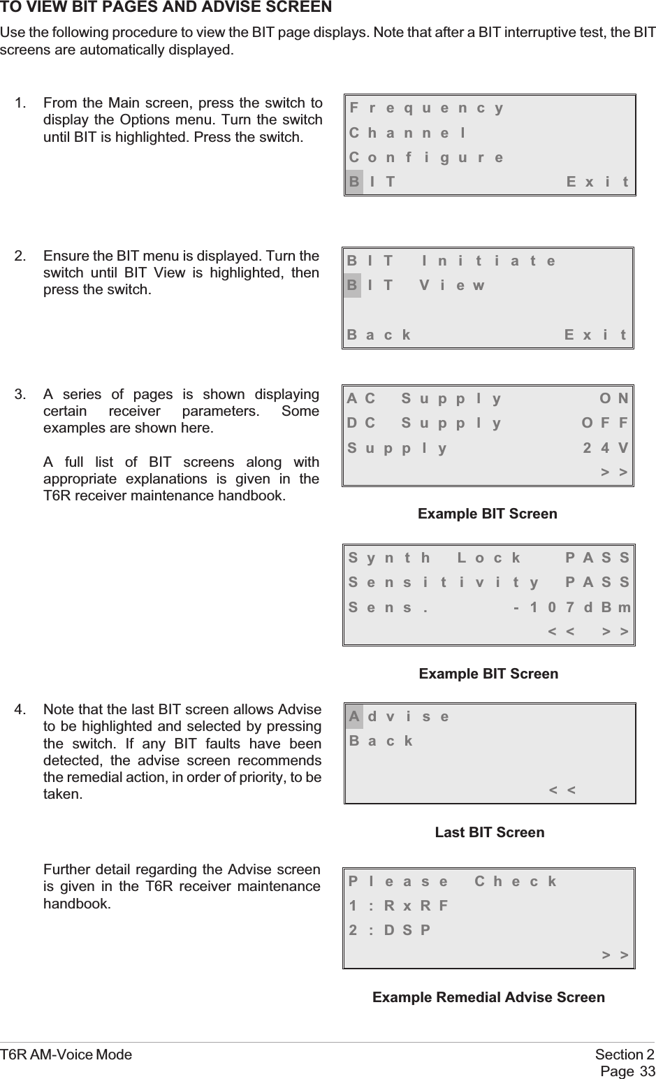
TO VIEW BIT PAGES AND ADVISE SCREENUse the following procedure to view the BIT page displays. Note that after a BIT interruptive test, the BITscreens are automatically displayed.1. From the Main screen, press the switch todisplay the Options menu. Turn the switchuntil BIT is highlighted. Press the switch.2. Ensure the BIT menu is displayed. Turn theswitch until BIT View is highlighted, thenpress the switch.3. A series of pages is shown displayingcertain receiver parameters. Someexamples are shown here.A full list of BIT screens along withappropriate explanations is given in theT6R receiver maintenance handbook.4. Note that the last BIT screen allows Adviseto be highlighted and selected by pressingthe switch. If any BIT faults have beendetected, the advise screen recommendsthe remedial action, in order of priority, to betaken.Further detail regarding the Advise screenis given in the T6R receiver maintenancehandbook.T6R AM-Voice Mode Section 2Page 33FrequencyChanne lCon f i gu r eBIT Exi tBIT Ini t iateBIT ViewBack Ex i tSyn t h Lock PASSSens i t i v i t y PASSSens . - 107dBm<< >>Example BIT ScreenAC Supp l y ONDC Supp l y OFFSupp l y 24V>>Example BIT ScreenAdviseBack<<Last BIT ScreenPl ease Check1 :RxRF2:DSP>>Example Remedial Advise Screen
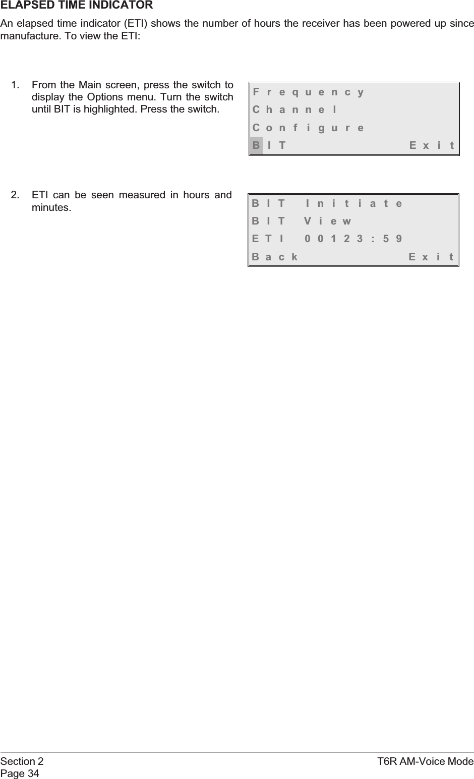
ELAPSED TIME INDICATORAn elapsed time indicator (ETI) shows the number of hours the receiver has been powered up sincemanufacture. To view the ETI:1. From the Main screen, press the switch todisplay the Options menu. Turn the switchuntil BIT is highlighted. Press the switch.2. ETI can be seen measured in hours andminutes.Section 2 T6R AM-Voice ModePage 34FrequencyChanne lCon f i gu r eBIT Exi tBIT Ini t iateBIT ViewETI 00123:59Back Ex i t
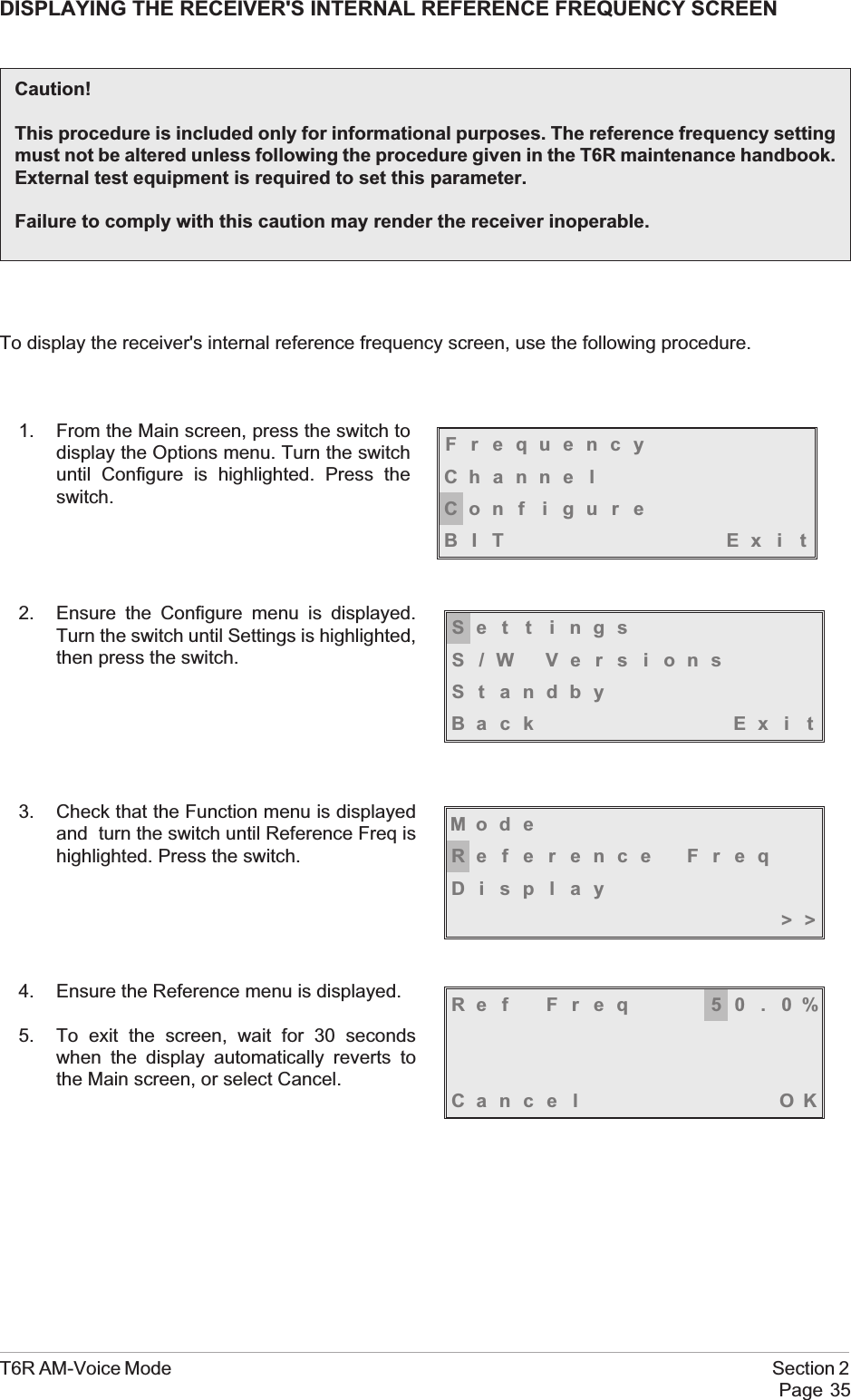
DISPLAYING THE RECEIVER'S INTERNAL REFERENCE FREQUENCY SCREENTo display the receiver's internal reference frequency screen, use the following procedure.1. From the Main screen, press the switch todisplay the Options menu. Turn the switchuntil Configure is highlighted. Press theswitch.2. Ensure the Configure menu is displayed.Turn the switch until Settings is highlighted,then press the switch.3. Check that the Function menu is displayedand turn the switch until Reference Freq ishighlighted. Press the switch.4. Ensure the Reference menu is displayed.5. To exit the screen, wait for 30 secondswhen the display automatically reverts tothe Main screen, or select Cancel.T6R AM-Voice Mode Section 2Page 35Caution!This procedure is included only for informational purposes. The reference frequency settingmust not be altered unless following the procedure given in the T6R maintenance handbook.External test equipment is required to set this parameter.Failure to comply with this caution may render the receiver inoperable.FrequencyChanne lCon f i gu r eBIT Exi tSe t t i ngsS/W VersionsSt andbyBack Ex i tMod eReference FreqDisplay>>Ref Freq 50.0%Cance l OK
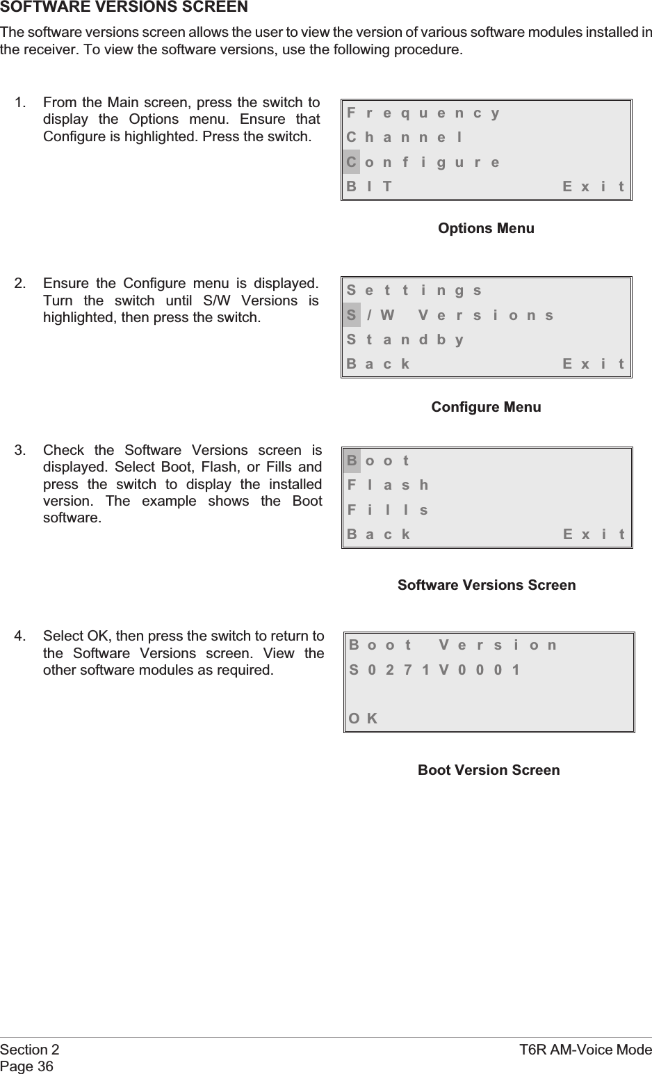
SOFTWARE VERSIONS SCREENThe software versions screen allows the user to view the version of various software modules installed inthe receiver. To view the software versions, use the following procedure.1. From the Main screen, press the switch todisplay the Options menu. Ensure thatConfigure is highlighted. Press the switch.2. Ensure the Configure menu is displayed.Turn the switch until S/W Versions ishighlighted, then press the switch.3. Check the Software Versions screen isdisplayed. Select Boot, Flash, or Fills andpress the switch to display the installedversion. The example shows the Bootsoftware.4. Select OK, then press the switch to return tothe Software Versions screen. View theother software modules as required.Section 2 T6R AM-Voice ModePage 36FrequencyChanne lCon f i gu r eBIT Exi tOptions MenuSe t t i ngsS/W VersionsSt andbyBack Ex i tConfigure MenuBoo tFlashFillsBack Ex i tSoftware Versions ScreenBoot VersionS0271V0001OKBoot Version Screen

Navigation menu