Park Air Systems B6100 VHF Fixed Ground Based Aeronautical Receiver User Manual T6R User Guide vp
Park Air Systems Limited VHF Fixed Ground Based Aeronautical Receiver T6R User Guide vp
Contents
- 1. Exhibit D User guide
- 2. Exhibit F sales literature
Exhibit D User guide
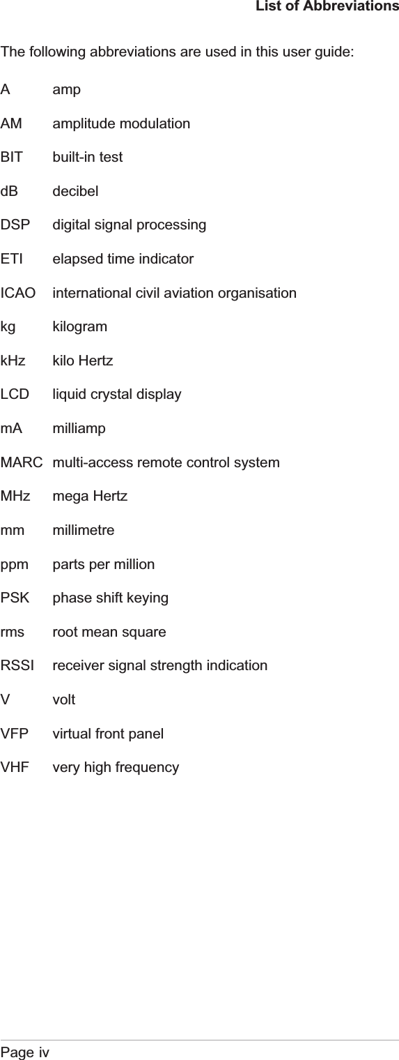
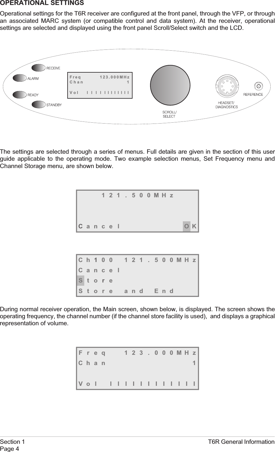
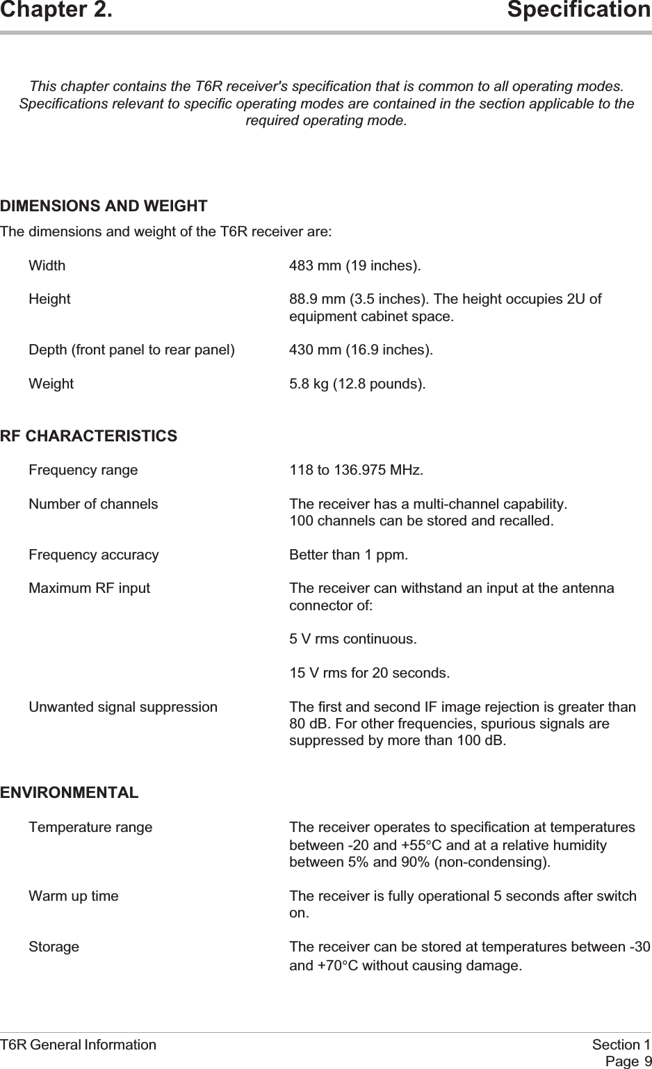
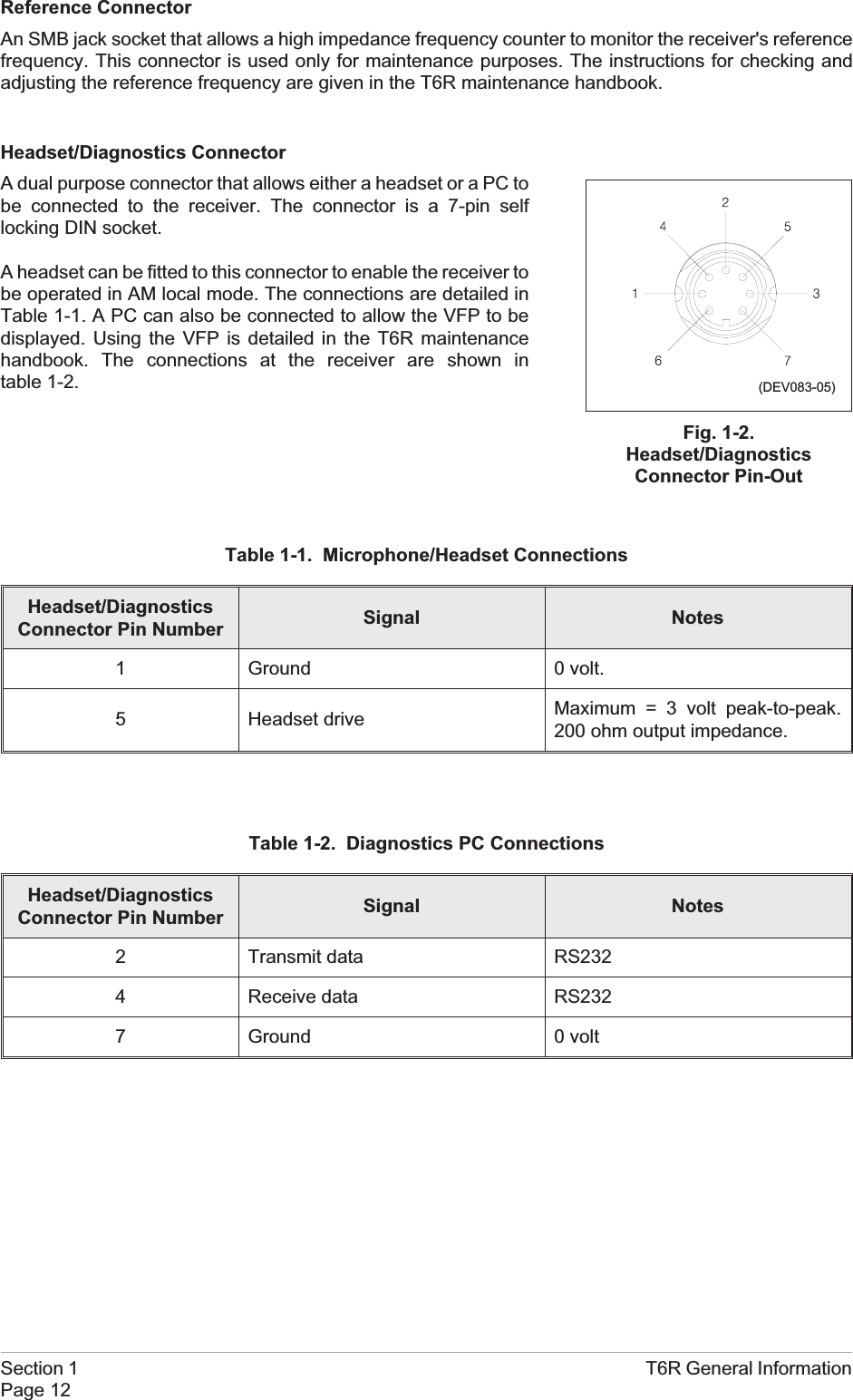

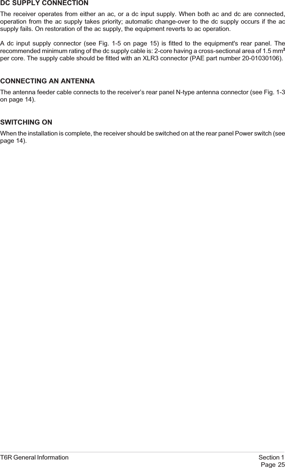
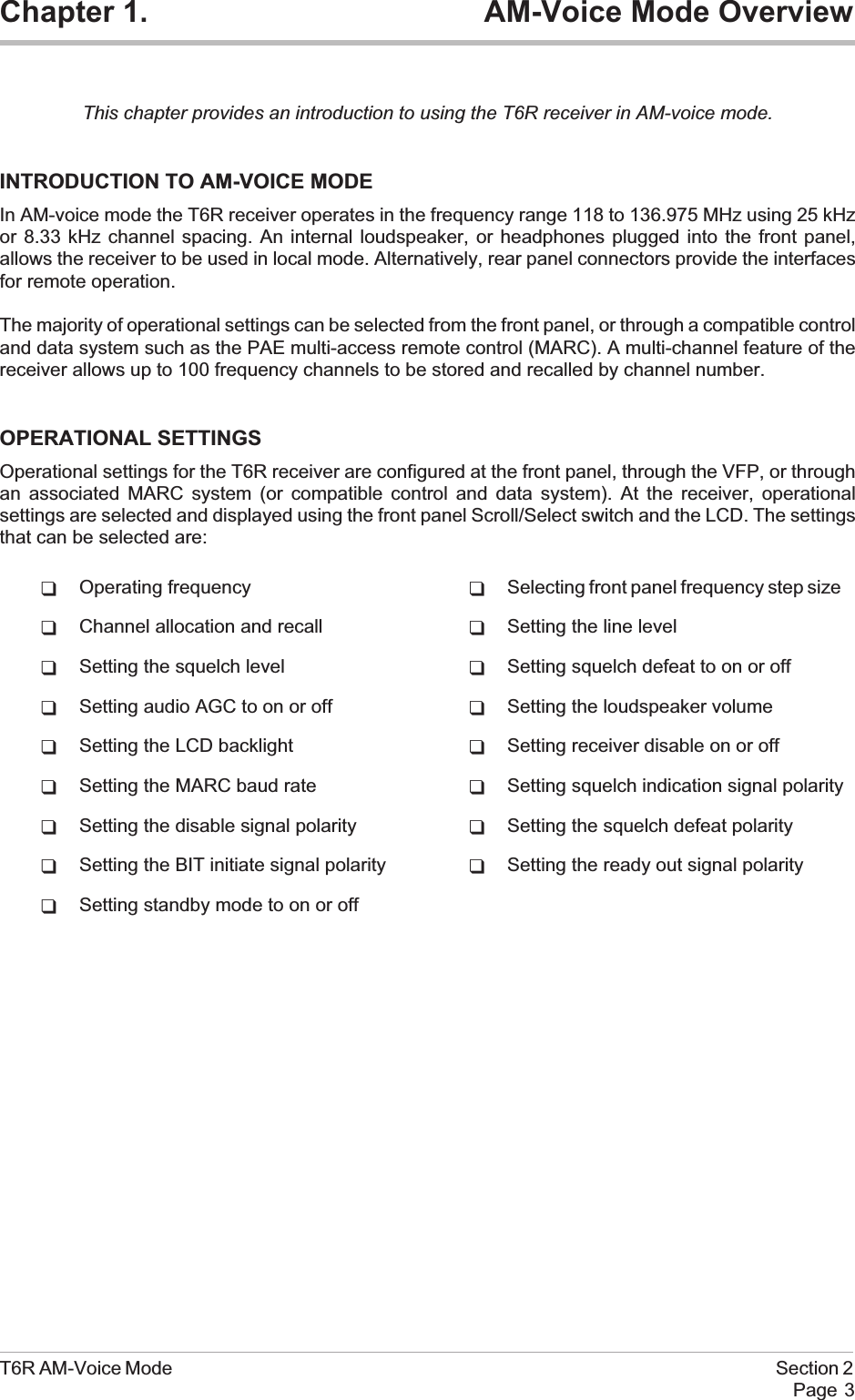
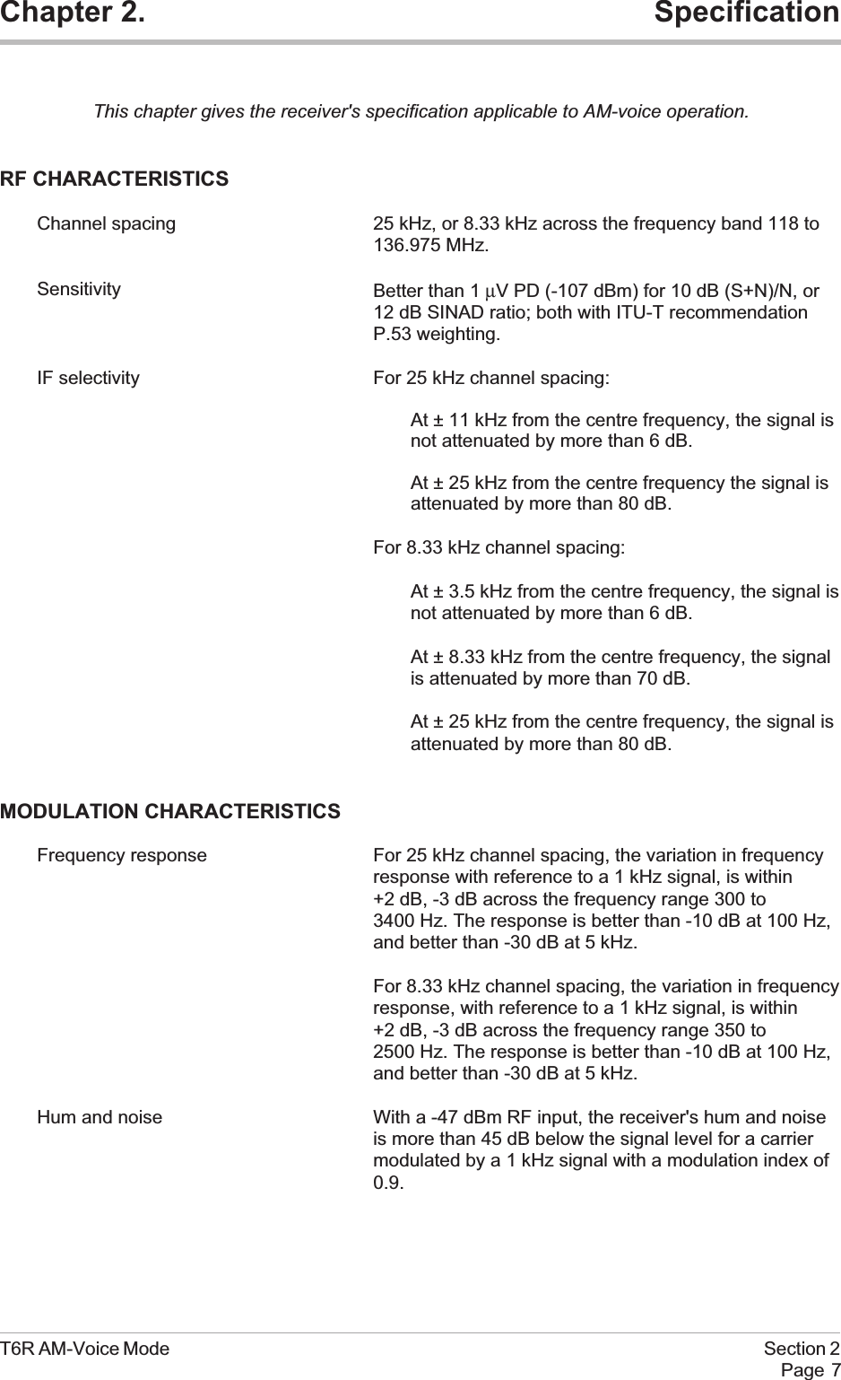
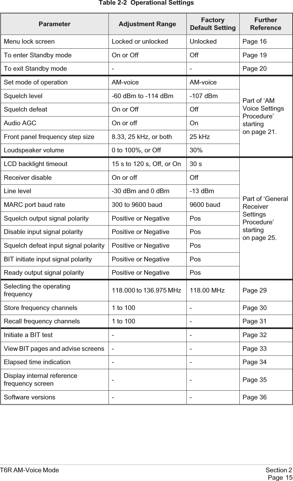
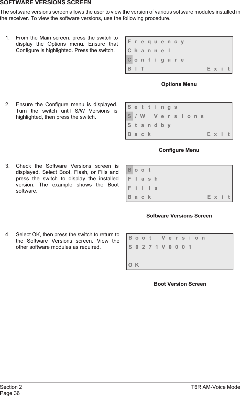
![TO ENTER AND EXIT STANDBY MODEStandby mode is a power saving feature that can be used for non-operational receivers. When instandby mode, most of the receiver's circuits are inactive, the LCD is blanked, and there is no audiooutput.To Enter Standby ModeTo put the receiver into standby mode, use the following procedure.1. From the Main screen, press the switch todisplay the Options menu. Ensure thatConfigure is highlighted. Press the switch.2. Ensure the Configure menu is displayed.Turn the switch until Standby is highlighted,then press the switch.3. Check that the Standby menu is displayed.Turn the switch until Yes is highlighted, thenpress the switch. [To abandon thisprocedure, select No instead of Yes andthen press the switch.]4. Check that the LCD blanks, and the front panel STANDBY indicator lights.5. The receiver is now in standby mode. To exit standby, see the next procedure.T6R AM-Voice Mode Section 2Page 19FrequencyChanne lCon f i gu r eBIT Exi tSe t t i ngsS/W VersionsSt andbyBack Ex i tPut radio intoSt andby mode ?YES NO](https://usermanual.wiki/Park-Air-Systems/B6100.Exhibit-D-User-guide/User-Guide-93779-Page-49.png)
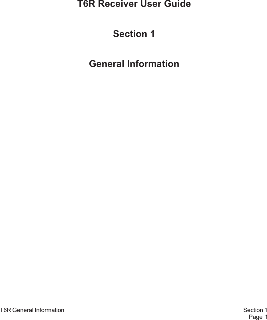
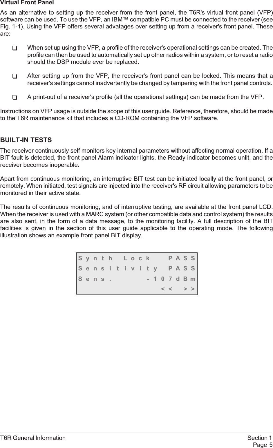
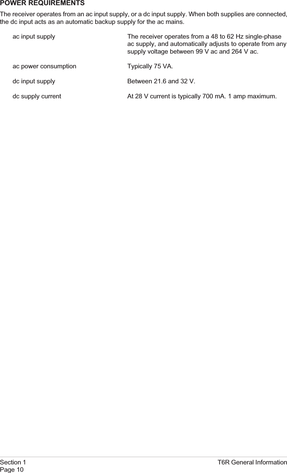
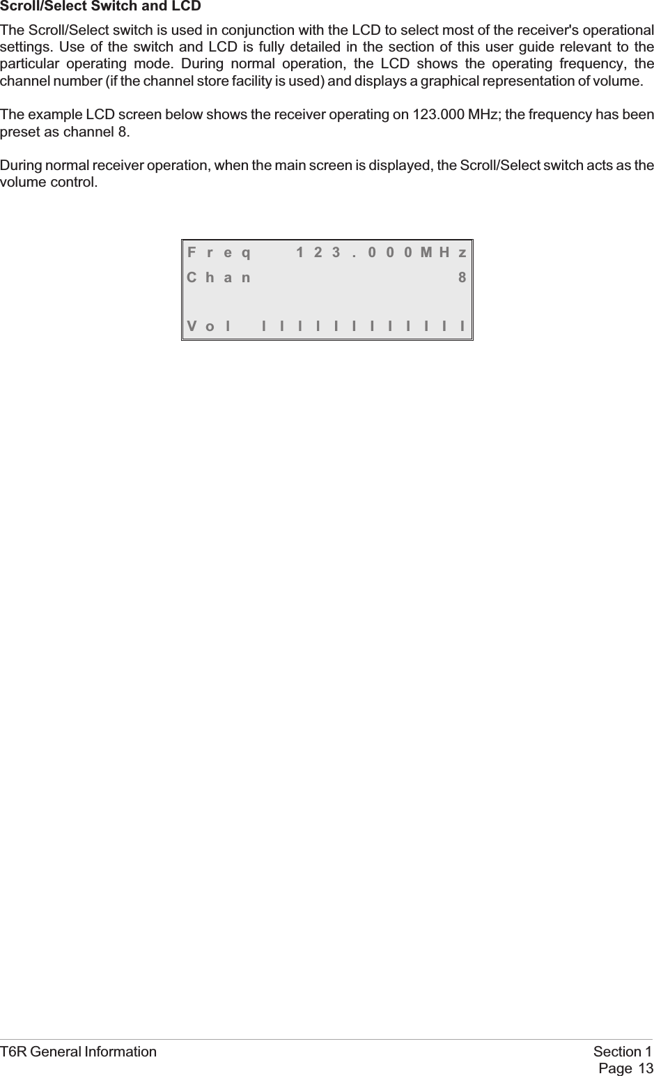
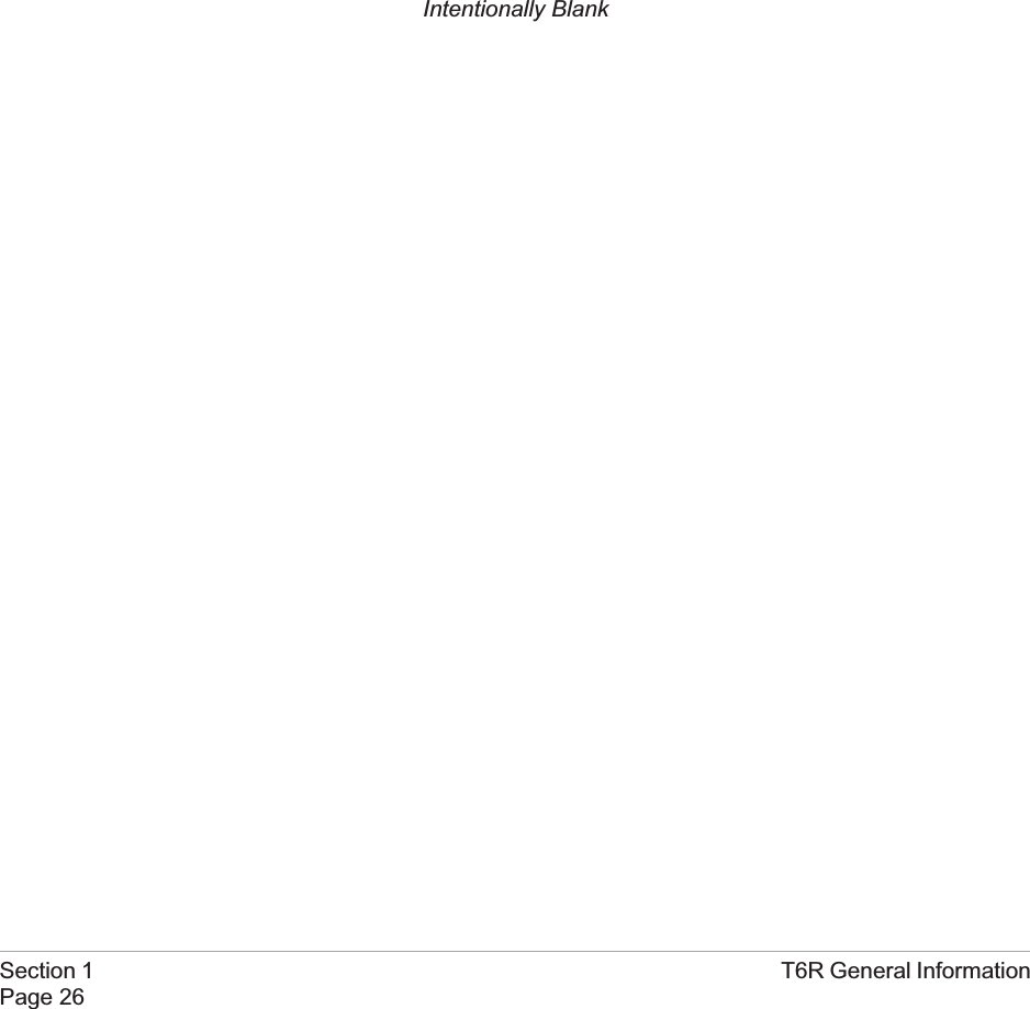
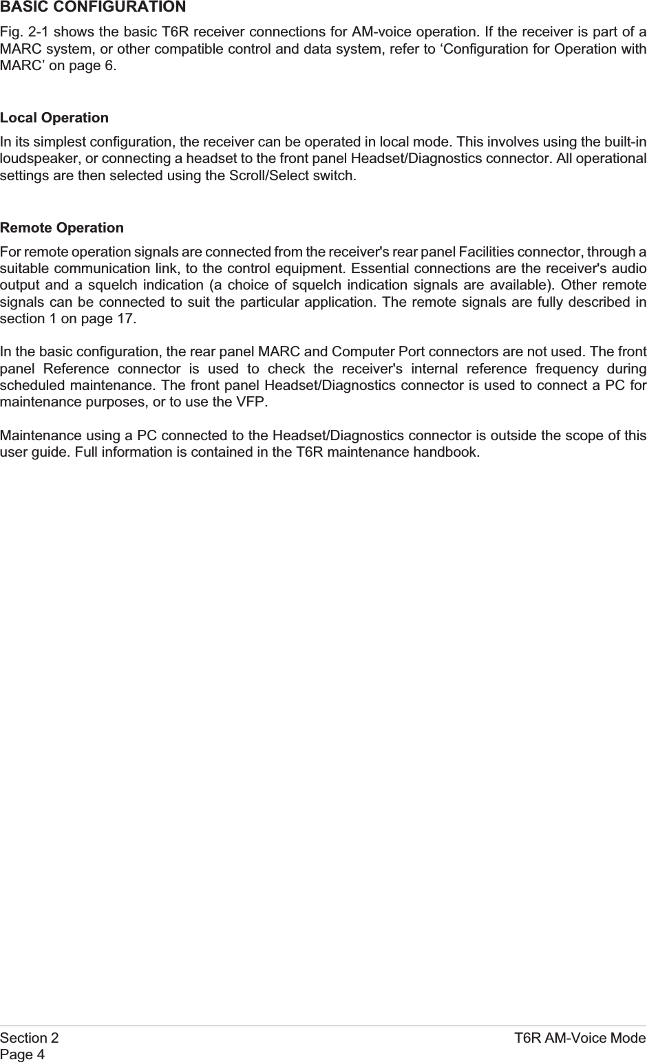
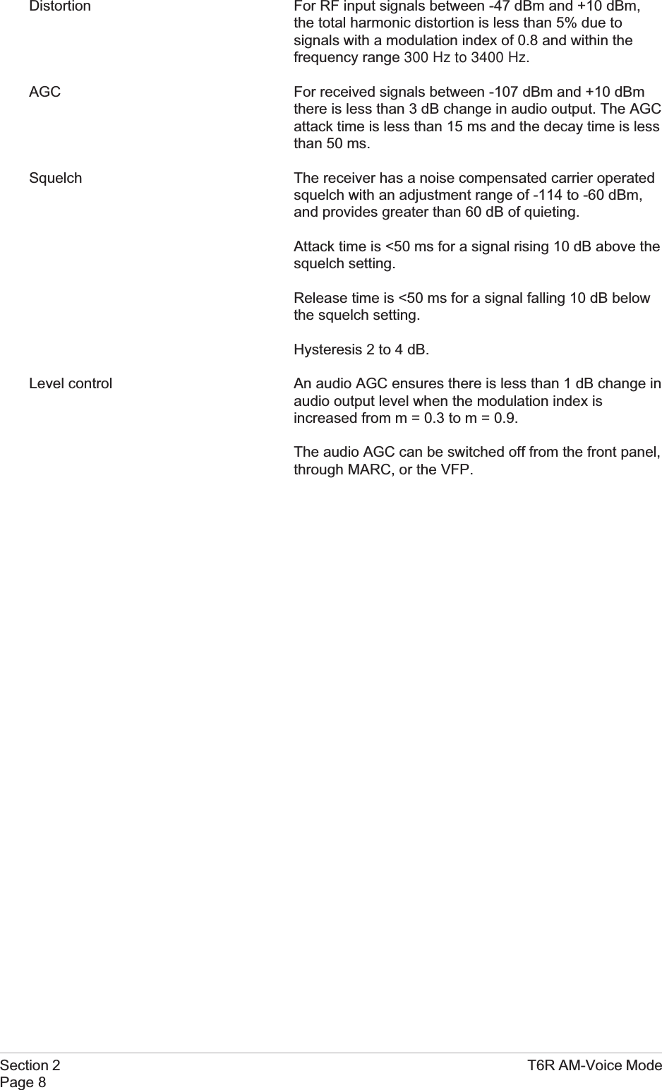
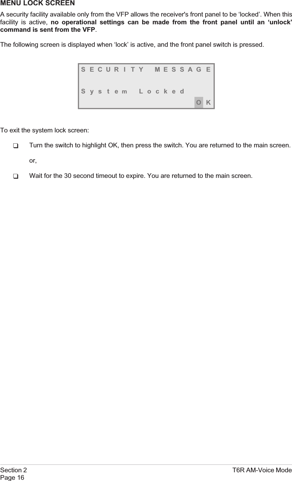
![To Exit Standby ModeStandby mode is indicated by the front panel STANDBY indicator being lit and the LCD being blanked.To exit this mode, use the following procedure.1. Press the switch and check that the Exitmenu is displayed.2. Turn the switch until YES is highlighted,then press the switch. [To abandon thisprocedure, select No instead of Yes andthen press the switch.]3. Check that the Main screen is displayed and that the front panel STANDBY indicator is unlit.4. The receiver is now ready for normal use.Section 2 T6R AM-Voice ModePage 20Ex i t St andbyMod eYES NOFreq 123 . 000MHzVo l llllllllllll](https://usermanual.wiki/Park-Air-Systems/B6100.Exhibit-D-User-guide/User-Guide-93779-Page-50.png)
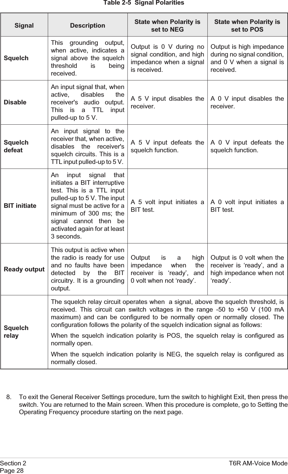
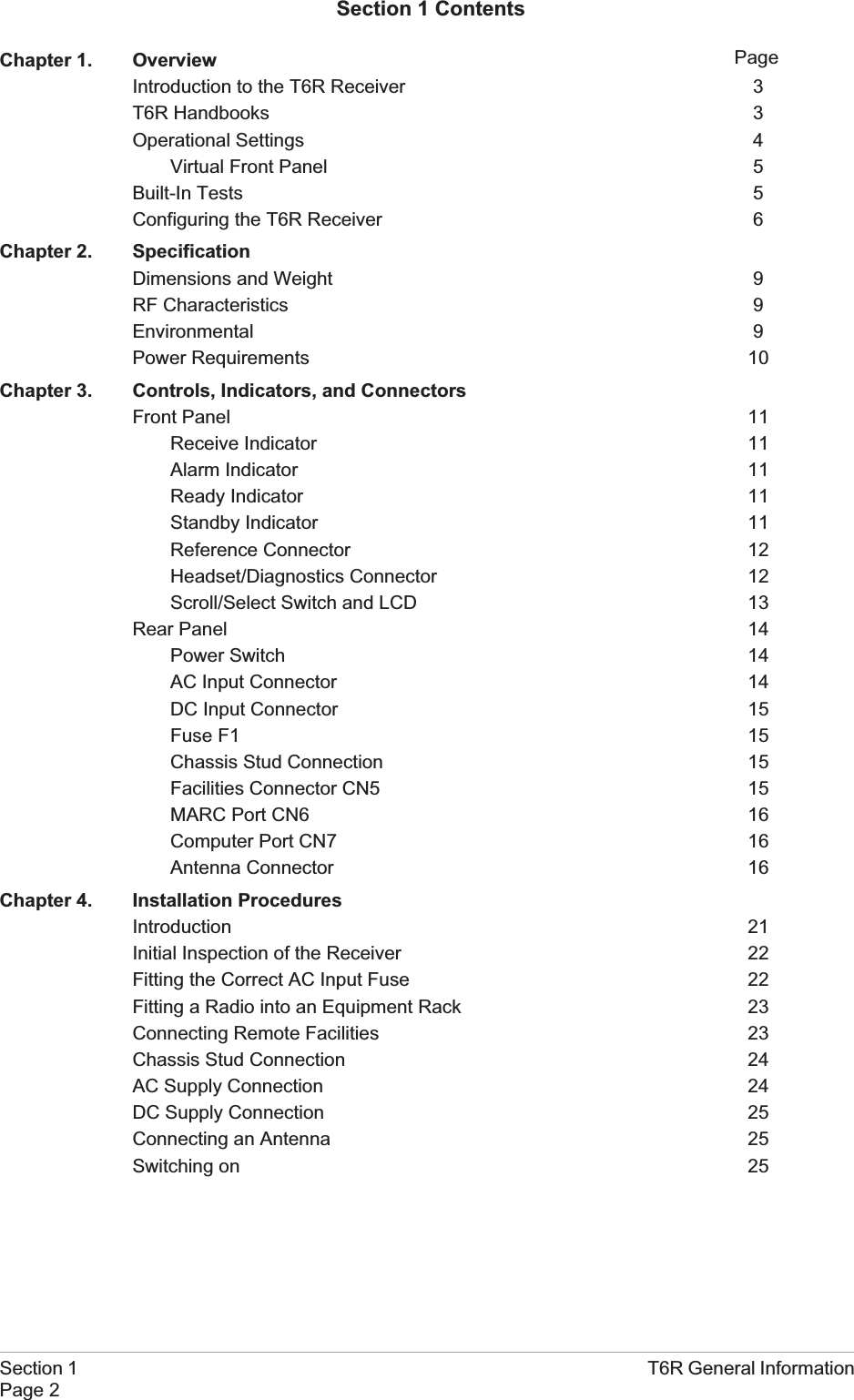
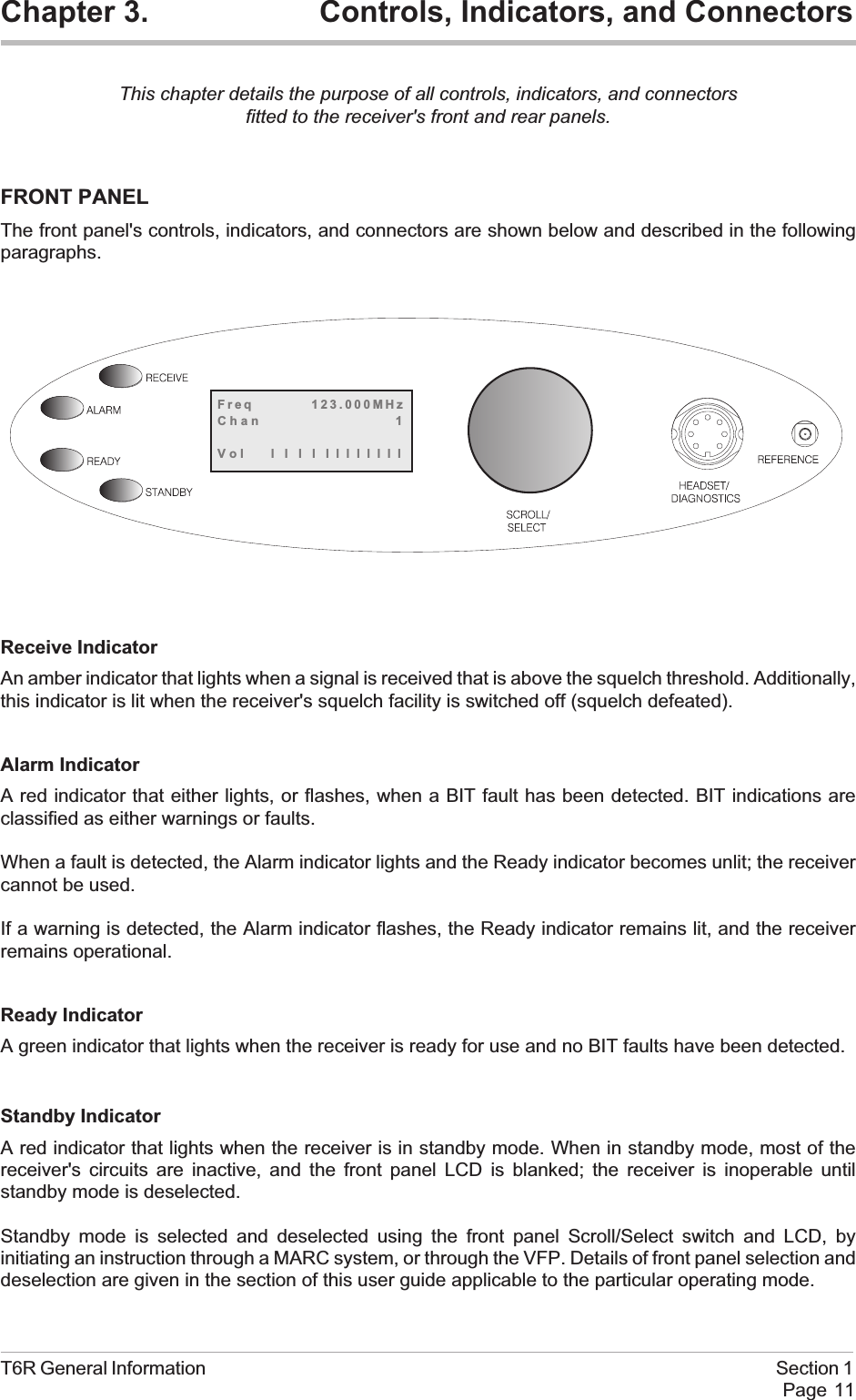
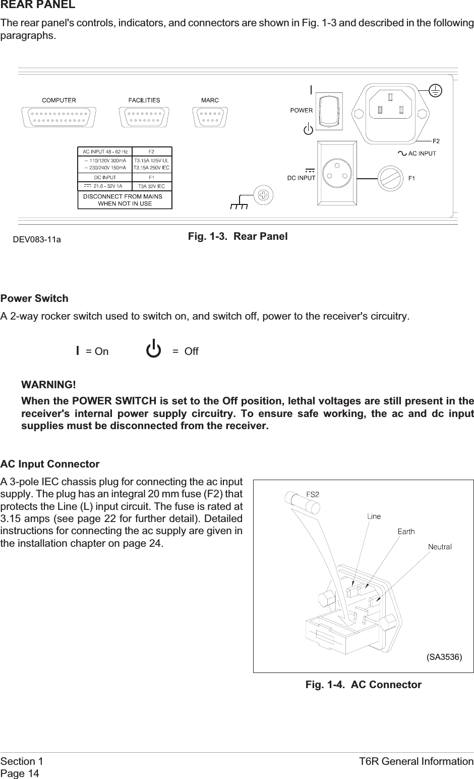
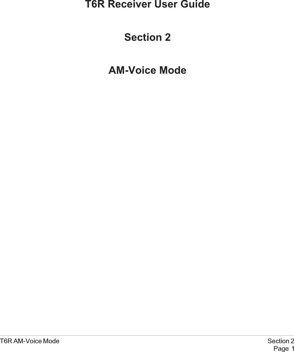
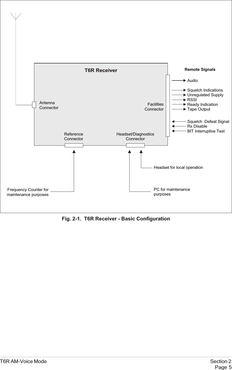
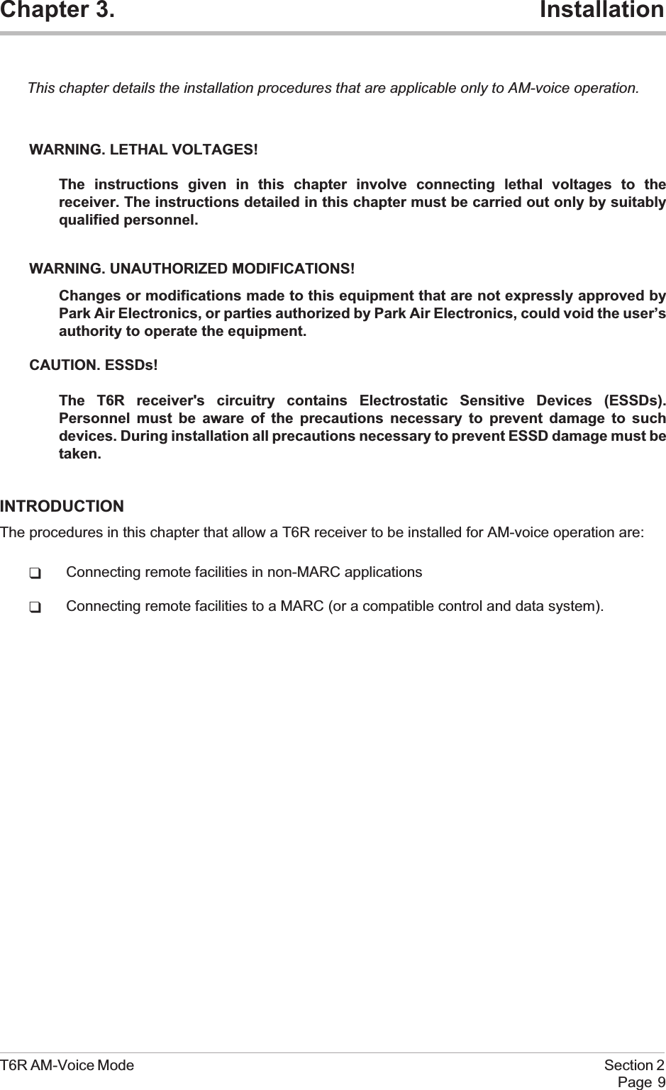
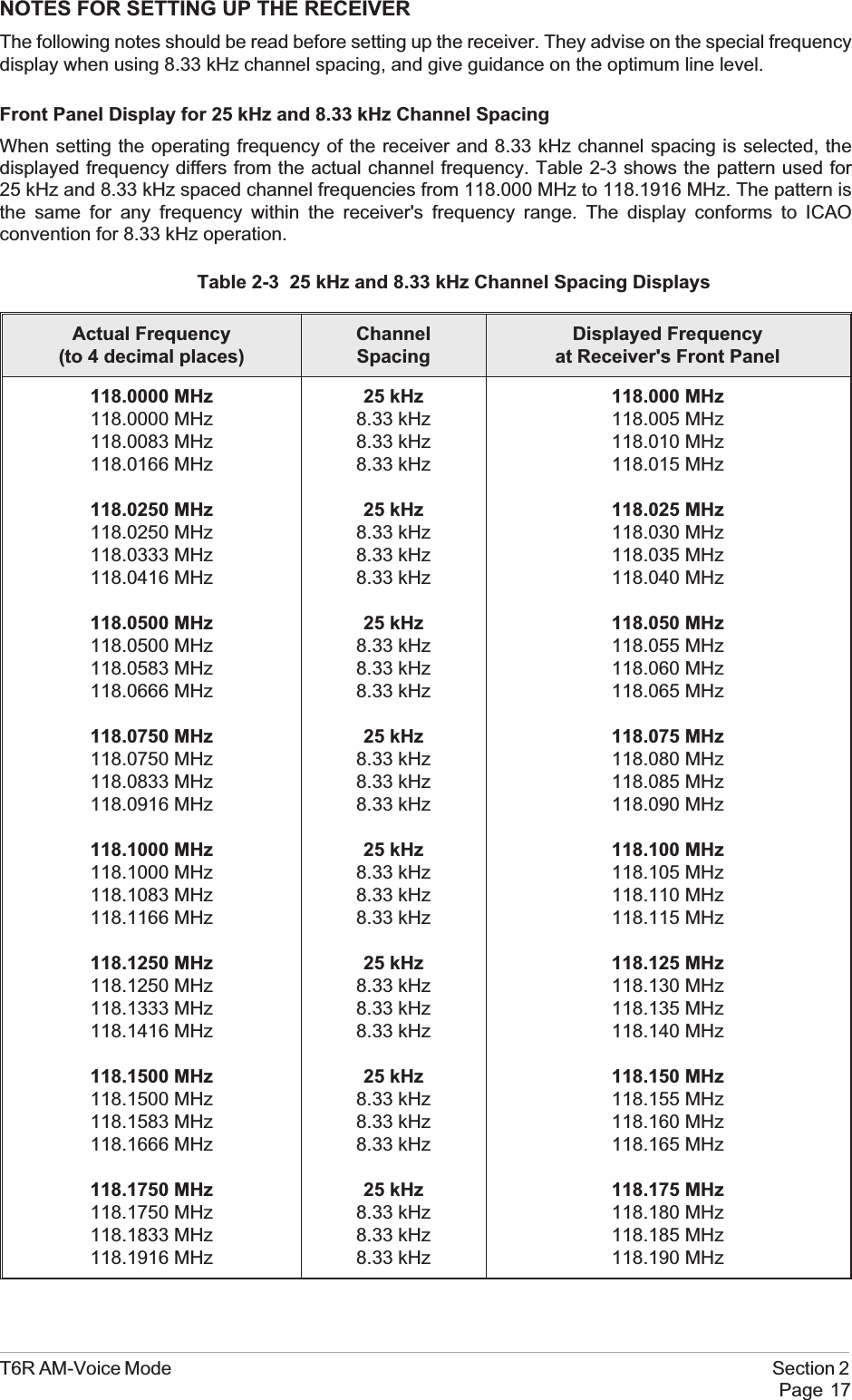
![5. Setting the Squelch Level.[Factory default setting: -107 dBm]The receiver's squelch level can be setbetween -60 dBm and -114 dBm.To set the squelch level, ensure Squelch ishighlighted. Press the switch. Turn the switchclockwise or anti-clockwise to increase ordecrease the value. When the required valueis displayed, press the switch. Turn the switchclockwise to highlight Sql Defeat.6. Setting Squelch Defeat to On or Off.[Factory default setting: Off]The receiver's squelch facility can be switched on or off.Ensure that Sql Defeat is highlighted. Pressthe switch to toggle between On and Off.On = Squelch Defeated. The receiver'ssquelch circuit does not operate and the frontpanel Receive indicator stays lit.Off = Squelch facility enabled. An audio outputis heard only when a signal greater than the squelch level is received.When the required setting is highlighted, turn the switch clockwise to highlight Audio AGC.7. Setting the Audio AGC.[Factory default setting: On]The receiver's Audio AGC facility can beswitched On or Off.When set to on, the audio output level remainsconstant for received signal modulation depthsgreater than 30%.When set to off, the audio output level isproportional to the received signal modulationdepth.To make the required setting, ensure Audio AGC is highlighted. Press the switch to togglebetween On and Off.When the required setting is highlighted, turn the switch clockwise to highlight Channel Spacing.Section 2 T6R AM-Voice ModePage 22Squelch -107dBmSql Defeat OFFAu d i o AGC ON>>Mode Specific Settings MenuSquelch -107dBmSql Defeat OFFAu d i o AGC ON>>Squelch -107dBmSql Defeat OFFAu d i o AGC ON>>](https://usermanual.wiki/Park-Air-Systems/B6100.Exhibit-D-User-guide/User-Guide-93779-Page-52.png)
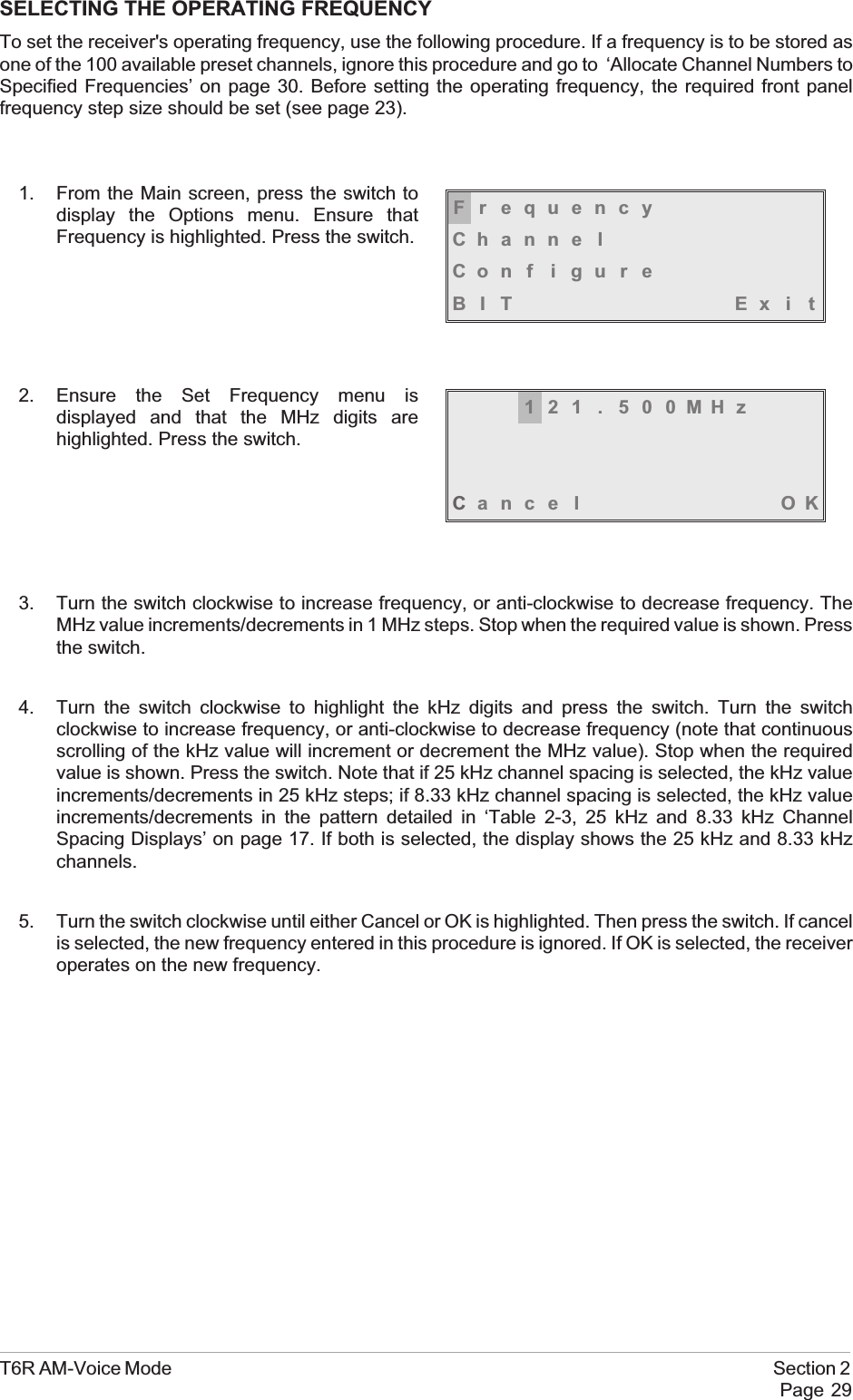
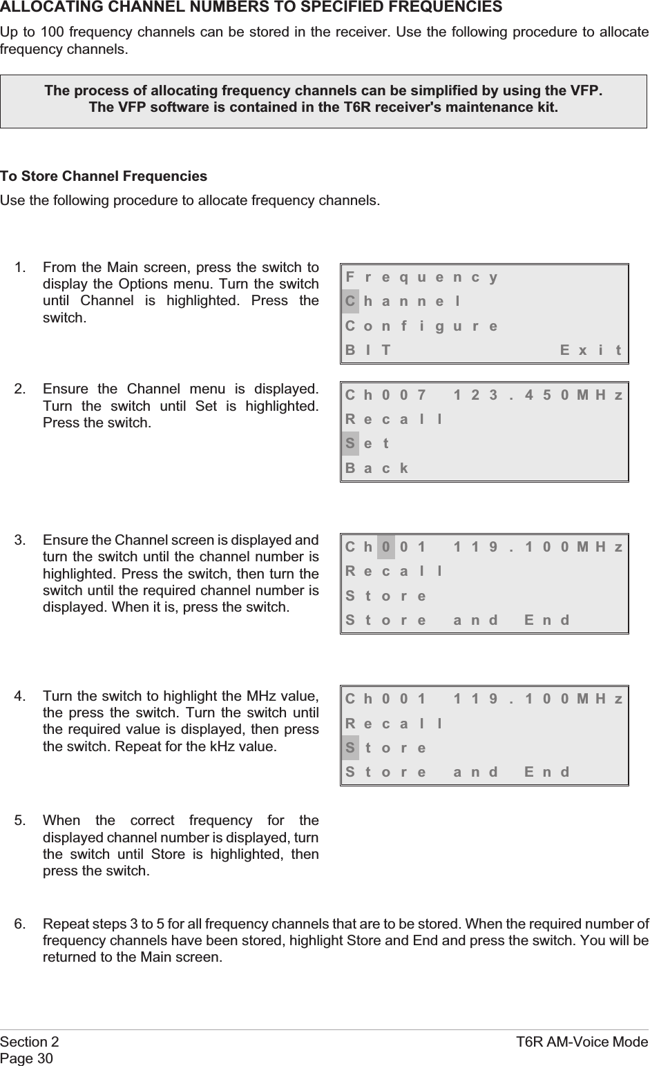
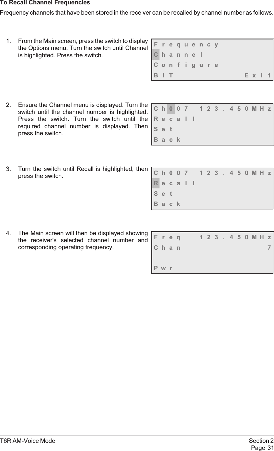
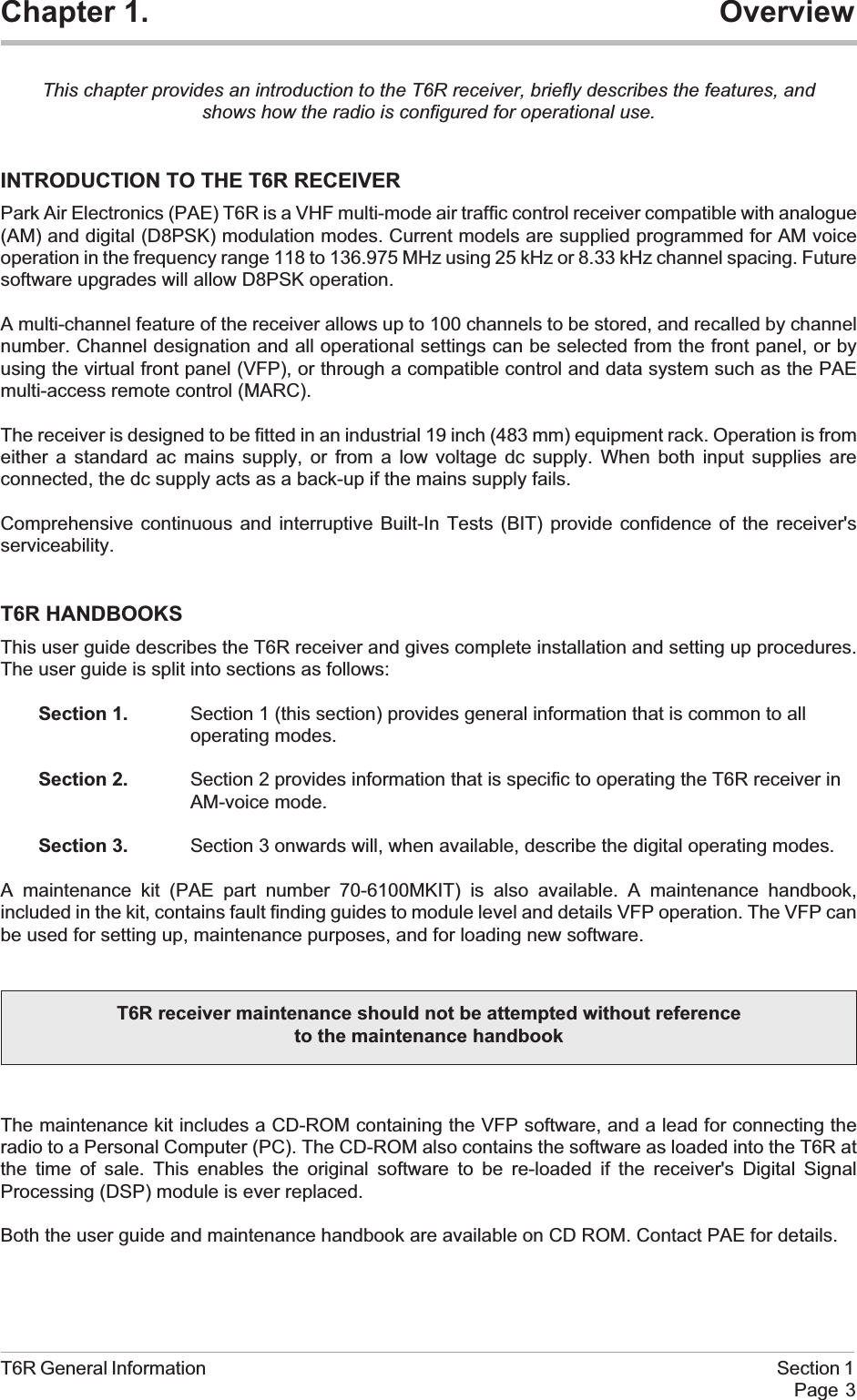
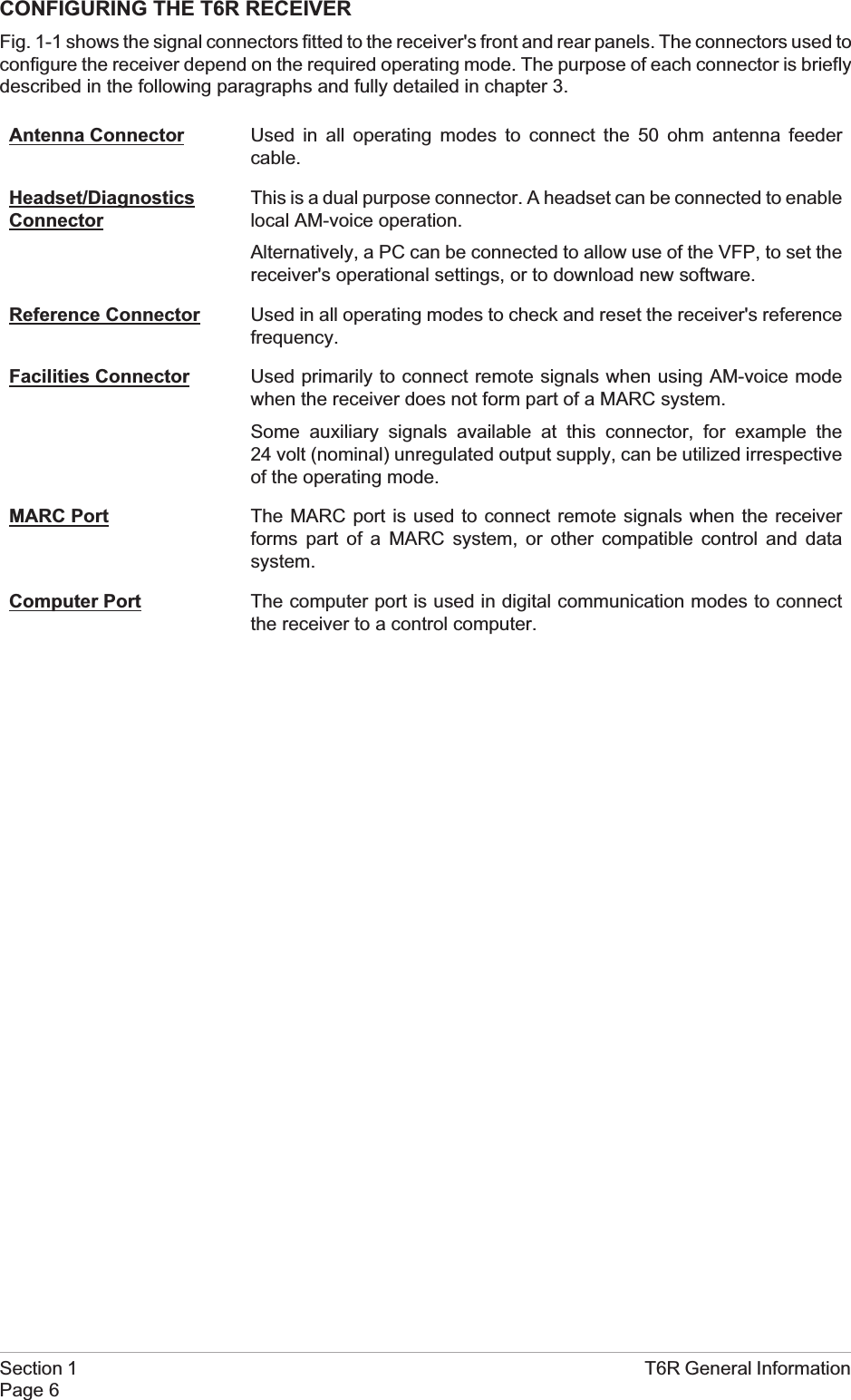
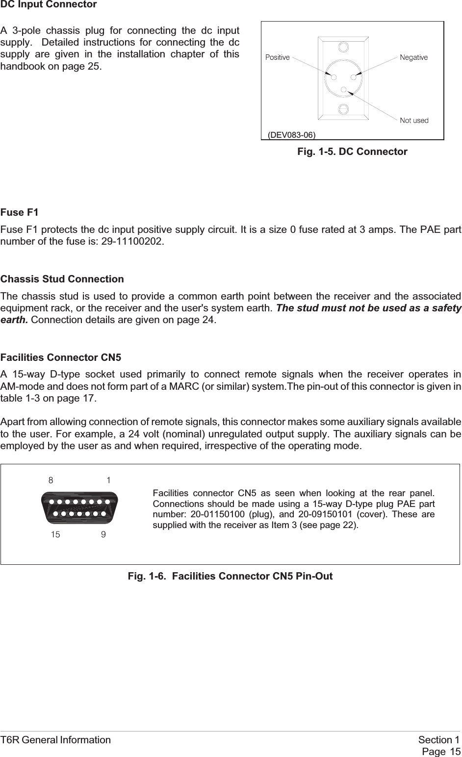
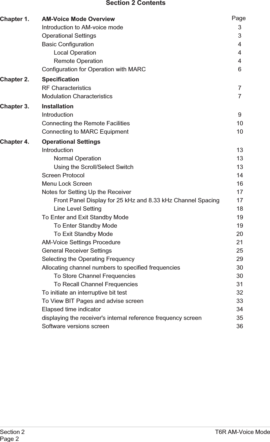
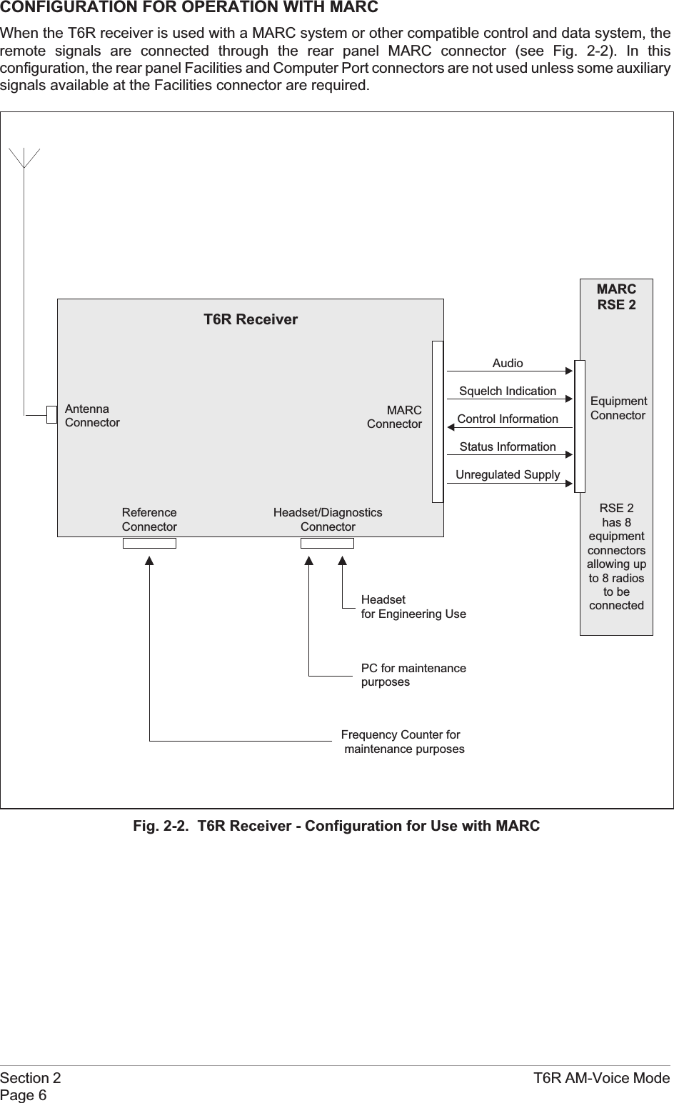
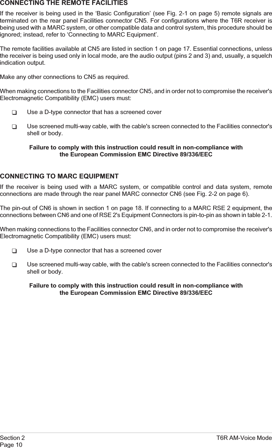
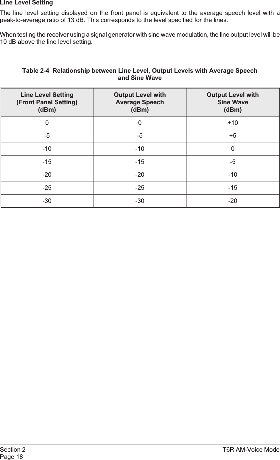
![8. Setting the Front Panel Frequency Step Size.[Factory default setting: 25 kHz]The receiver's channel spacing can be 25 kHz, or 8.33 kHz. The radio automatically sets thecorrect channel spacing for the frequency that is entered at the front panel. This setting, which isonly for the user's convenience, alters front panel frequency step size.qIf all channels to be selected or stored are 25 kHz spaced channels, then 25 should beselected.qIf all channels to be selected or stored are 8.33 kHz spaced channels, then 8.3 should beselected.qIf a mixture of the two are required, both 25 and 8.3 should be selected.To select the required spacing, ensure thatChannel Spacing is highlighted and press theswitch.Check that the Channel Spacing menu isdisplayed and that Spacing is highlighted.Press the switch to change between 25 kHz,8.3 kHz, and both. When the required value isdisplayed, turn the switch to highlight OK, thenpress the switch again. You will be returned tothe Mode Specific Settings menu.T6R AM-Voice Mode Section 2Page 23Channe l Spac i ngLoudspeakerBackEx i t <<Spac ing 25kHz8.3kHzCance l OKChannel Spacing Menu (Both Selected)](https://usermanual.wiki/Park-Air-Systems/B6100.Exhibit-D-User-guide/User-Guide-93779-Page-53.png)
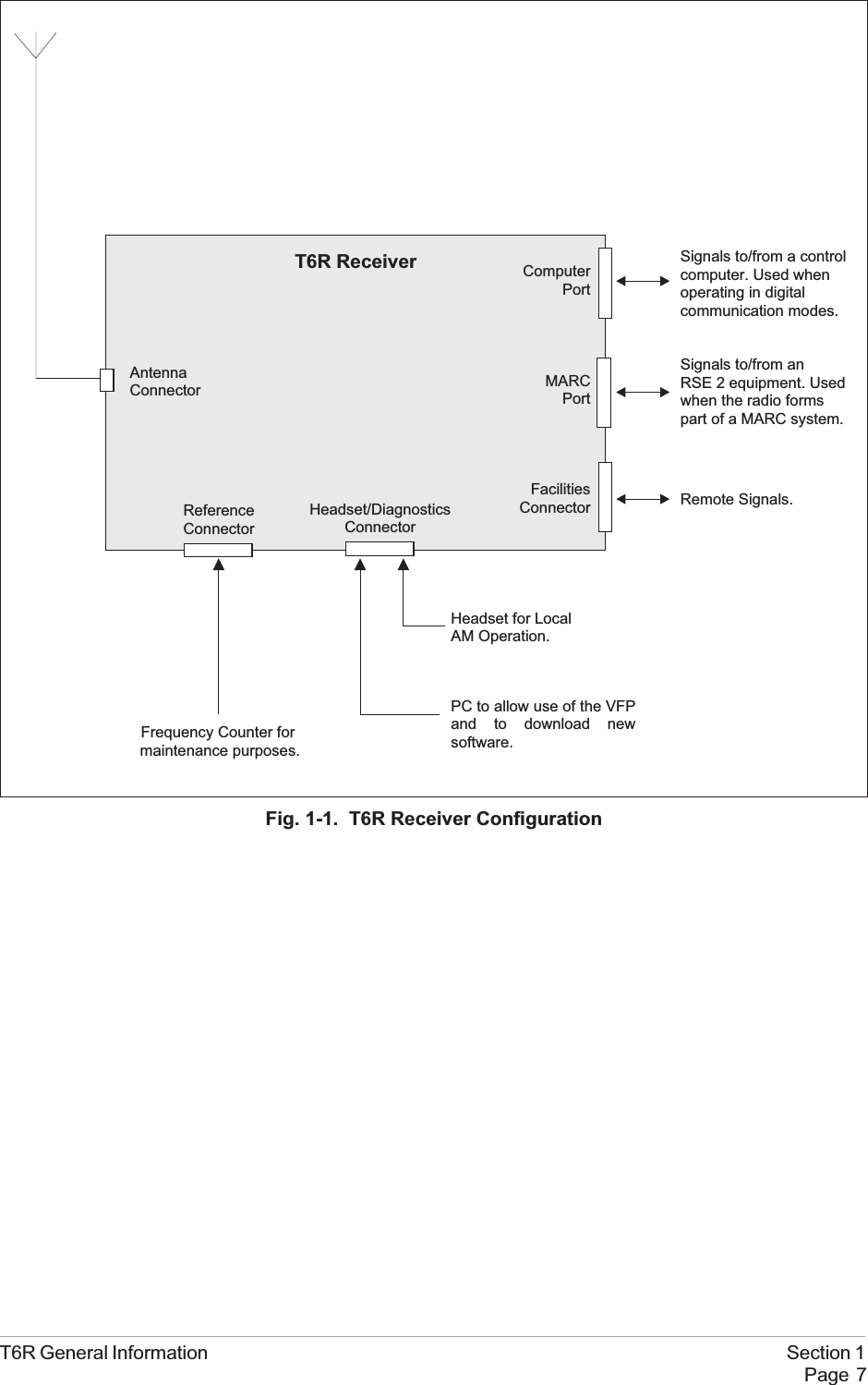
![9. Setting the Loudspeaker/Headset Volume.[Factory default setting: 30% Volume; Loudspeaker On]The receiver's loudspeaker and headset volume can be set, and the speaker can be switched onor off during this procedure.Turn the switch clockwise until Loudspeaker is highlighted, then press the switch.Ensure that the Loudspeaker menu isdisplayed and that Volume is highlighted.Press the switch. Turn the switch clockwise toincrease volume, or anti-clockwise todecrease volume. When the required value(0 to 100%) is displayed, press the switch.Turnthe switch clockwise until OK is highlighted,then press the switch.To turn the loudspeaker on and off, highlightSpeaker and press the switch to togglebetween On and Off. When the requiredsetting is displayed, turn the switch to highlightOK, then press the switch. You are returned tothe Mode Specific Settings menu.10. To exit the AM-Voice Settings Procedure, turn the switch to highlight Exit, then press the switch.You are returned to the Main screen. When this procedure is complete, go to the GeneralReceiver Settings procedure starting on the next page.Section 2 T6R AM-Voice ModePage 24Volume 030%Speaker ONOKChanne l Spac i ngLoudspeakerBackEx i t <<](https://usermanual.wiki/Park-Air-Systems/B6100.Exhibit-D-User-guide/User-Guide-93779-Page-54.png)
![GENERAL RECEIVER SETTINGSDuring this procedure, the following parameters will be set:qLCD backlight qDisable on or offqLine level qMARC baud rateqSquelch output signal polarity qDisable input signal polarityqSquelch defeat polarity qBIT initiate signal polarityqReady output signal polarity1. From the Main screen, press the switch todisplay the Options menu. Turn the switchuntil Configure is highlighted. Press theswitch.2. Ensure the Configure menu is displayed.Turn the switch until Settings is highlighted,then press the switch.3. Setting the LCD Backlight.[Factory default setting: 30 s]Check that the Settings menu is displayedand turn the switch until Display ishighlighted. Press the switch.The LCD's backlight can be set to off,permanently on, or timed to stay on for aperiod between 15 and 120 seconds(adjustable in 15 second steps) after theScroll/Select switch was last operated.Ensure the Backlight menu is displayed andBacklight is highlighted. Press the switch.Turn the switch until the required setting isdisplayed, then press the switch. Turn theswitch clockwise until OK is highlighted, thenpress the switch. You are returned to theSettings menu.T6R AM-Voice Mode Section 2Page 25FrequencyChanne lCon f i gu r eBIT Exi tOptions MenuSe t t i ngsS/W VersionsSt andbyBack Ex i tConfigure MenuMod eReference FreqDisplay>>Settings MenuBack l i ght 030sCance l OK](https://usermanual.wiki/Park-Air-Systems/B6100.Exhibit-D-User-guide/User-Guide-93779-Page-55.png)
![4. Setting Disable On or Off.[Factory default setting: Off]Receiver disable can be set to either On or Off. When set to on, the receiver's audio output isdisabled. When set to off, audio is available through the internal loudspeaker, the headset, orthrough the remote audio lines.From the Settings menu, turn the switchclockwise until Disable is highlighted, thenpress the switch.Check that the Disable menu is displayed andDisable is highlighted. Pressing the switchtoggles between On and Off. When the correctsetting is displayed turn the switch clockwiseto highlight OK, then press the switch. You arereturned to the Settings menu.5. Setting the Line Level.[Factory default setting: -13 dBm]The audio line output level can be set to any value between -30 dBm and 0 dBm. Some notesregarding the optimum line level are given on page 18.From the Settings menu, turn the switchclockwise until Line Level is highlighted, thenpress the switch.Check that the Line Level menu is displayedand that Line Lvl is highlighted, then press theswitch.Turn the switch clockwise or anti-clockwise toincrease or decrease the value. When therequired value is displayed, press the switch.Turn the switch to highlight OK and then pressthe switch. You are returned to the Settings menu.Section 2 T6R AM-Voice ModePage 26DisableLine LevelMARC<< >>Disable ONCance l OKDisableLine LevelMARC<< >>Line Lvl -13dBmCance l OK](https://usermanual.wiki/Park-Air-Systems/B6100.Exhibit-D-User-guide/User-Guide-93779-Page-56.png)
![6. Setting the MARC Baud Rate.[Factory default setting: 9600]The baud rate must be set when the T6R receiver is connected to a MARC system (or othercompatible data and control system). The rate can be set to 300, 600, 1200, 2400, 4800, or 9600baud.From the Settings menu, turn the switchclockwise until MARC is highlighted, thenpress the switch.Ensure that the MARC menu is displayedand that Baud Rate is highlighted.Press the switch. Turn the switch until therequired value is displayed, then press theswitch. Turn the switch clockwise until OK ishighlighted, then press the switch. You arereturned to the Settings menu.7. Polarity Settings.The polarity of the following input and output signals is set using the Polarity menu:qSquelch output signalqDisable input signalqSquelch defeat input signalqBIT initiate input signalqReady output signal.To establish the required polarity for the input and output signals, refer to table 2-5.From the Settings menu, turn the switch untilPolarity is highlighted. Then press the switchto display the Polarity menu.To set the required polarity, turn the switch tohighlight the required parameter, then pressthe switch to toggle between NEG and POS.When all polarities have been set, highlightBack, and press the switch to return to theSettings menu.T6R AM-Voice Mode Section 2Page 27Baud Rate 9600Cance l OKDisableLine LevelMARC<< >>Disable NEGSquelch Out POSSquelch Def NEG>>BIT Ini t NEGReady Out POSBackEx i t <<Polarity MenuPolarityBackEx i t<<](https://usermanual.wiki/Park-Air-Systems/B6100.Exhibit-D-User-guide/User-Guide-93779-Page-57.png)