Park Air Systems B6100-S2 VHF fixed ground based aeronautical receiver User Manual t6r
Park Air Systems Limited VHF fixed ground based aeronautical receiver t6r
UserManual.wiki
>
Park Air Systems
>
B6100-S2 User Manual
>
User guide
Contents
1.
User guide
2.
Brochure
User guide
Navigation menu
Upload a User Manual
Namespaces
Wiki Guide
HTML
PDF
Info
Views
User Manual
Discussion / Help
Navigation
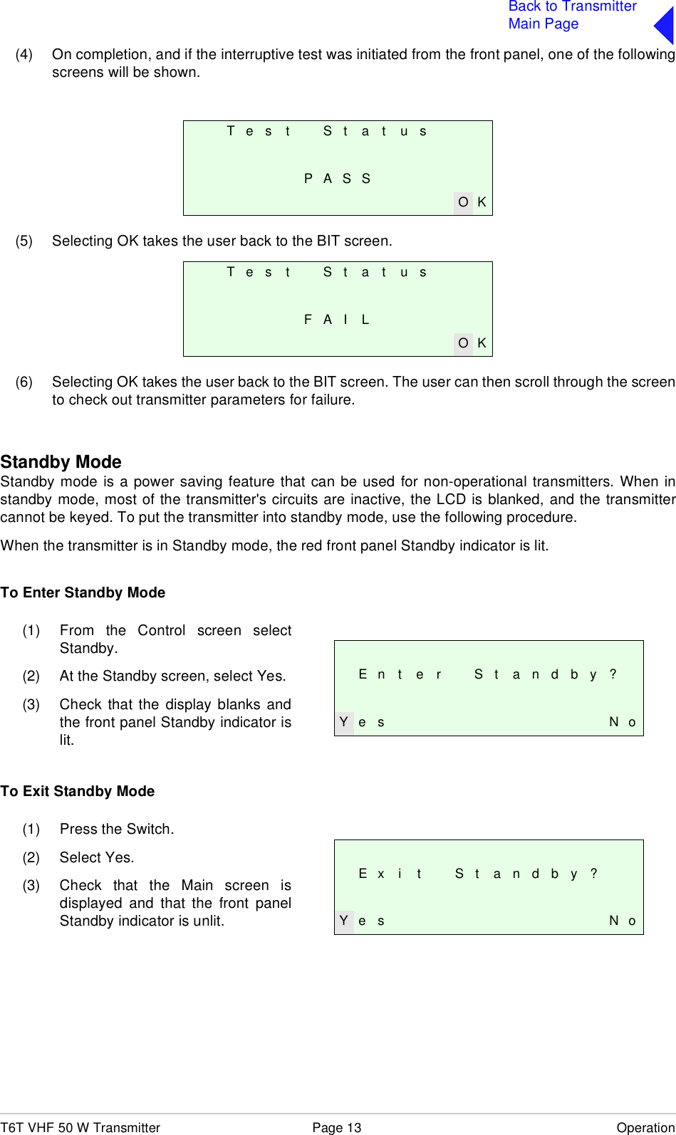
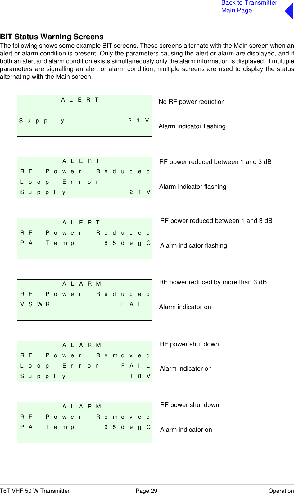
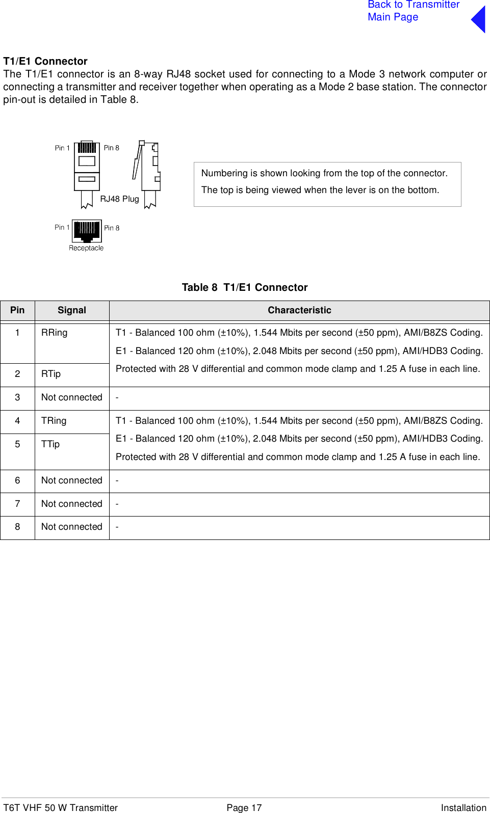
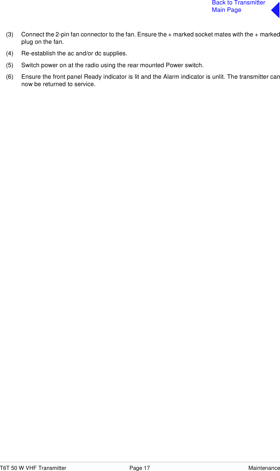
![T6T VHF 50 W Transmitter Page 27 OperationBack to TransmitterMain PageSoftware Configuration ScreensSoftware configuration screens are as follows:T 6 V H F 5 0 W T X1 1 8 - 1 3 6 . 9 7 5 M H zH i g h S t a b i l i t yE x i t > >B o o t S o f t w a r e65- xxxxxxxx/ vvE x i t < < > >B a s e S o f t w a r e65- xxxxxxxx/ vvE x i t < < > >M o d e S o f t w a r e65- xxxxxxxx/ vvE x i t < < > >F i l l 1 S o f t w a r e65- xxxxxxxx/ vv[ D e s c r i p t i o n ]E x i t < < > >F i l l 2 S o f t w a r e65- xxxxxxxx/ vv[ D e s c r i p t i o n ]E x i t < < > >Second line variation for WB radios reads 112-155.975 MHz.Third line variation for WB radios is blank.65-xxxxxxxx represents the software partnumber and /v v represents its version.65-xxxxxxxx represents the software partnumber and /v v represents its version.Current mode running. 65-xxxxxxxxrepresents the software part number and /v vrepresents its version.65-xxxxxxxx represents the software partnumber and /v v represents its version.65-xxxxxxxx represents the software partnumber and /v v represents its version.](https://usermanual.wiki/Park-Air-Systems/B6100-S2.User-guide/User-Guide-587835-Page-37.png)
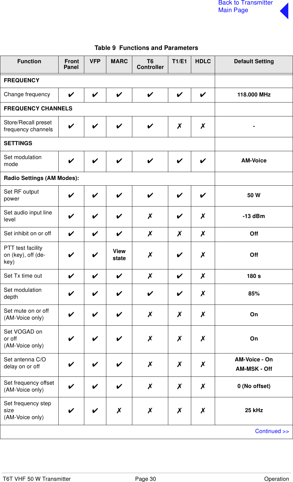
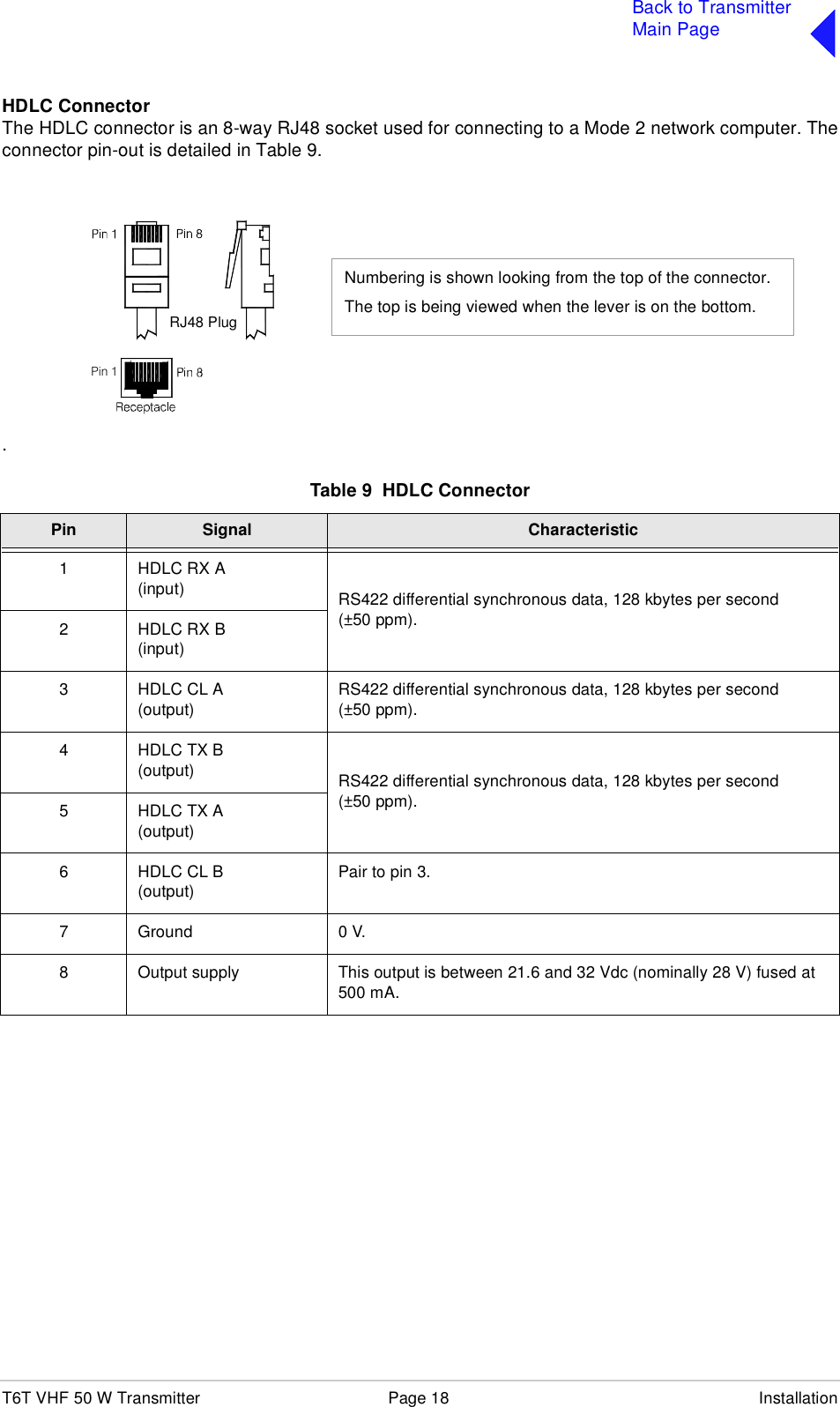
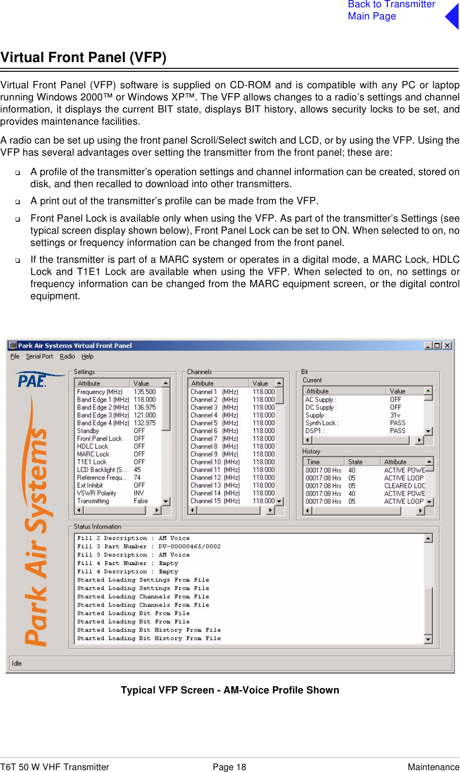
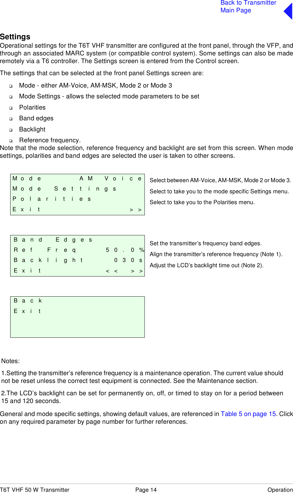
![T6T VHF 50 W Transmitter Page 28 OperationBack to TransmitterMain PageBand EdgesThe frequency range of the transmitter is 118 to 136.975 MHz for the B6350/NB version, or 112 to155.975 MHz for the B6350/WB version.If required, transmission can be limited to either one or two smaller parts of the frequency band by settingthe band edges BE1 to BE4. Transmission is possible between BE1 and BE2 frequencies, andfrequencies between BE3 and BE4. Table 8 Band Edge ValuesBE1 BE2 BE3 BE4B6350/NB set so that operation is over the full frequency range.118.000 136.975 118.000 136.975B6350/WB set so that operation is over the full frequency range.112.000 155.975 112.000 155.975Example: Transmitter set to transmit only those frequencies in the range 120 to 130 MHz.120.000 130.000 120.000 130.000Example: Transmitter set to transmit only those frequencies in the ranges 120 to 125 MHz and 130 to 135 MHz.120.000 125.000 130.000 135.000F i l l 3 S o f t w a r e6 5 - x x x x x x x x / v v[ D e s c r i p t i o n ]F i l l 4 S o f t w a r e6 5 - x x x x x x x x / v v[ D e s c r i p t i o n ]65-xxxxxxxx represents the software part numberand /v v represents its version.65-xxxxxxxx represents the software part numberand /v v represents its version.B E 1 1 1 8 . 0 0 0 M H zB E 2 1 3 6 . 9 7 5 M H zB E 3 1 1 8 . 0 0 0 M H zE x i t > >B E 4 1 3 6 . 9 7 5 M H zE x i t < <The Band Edge screen is accessed from theControl screen.Band edge frequencies can be set only inincrements of 25 kHz.If the transmitter is required to operate over thefull range, the band edge parameters must be setto the lowest and highest values in the range (seeTable 8).](https://usermanual.wiki/Park-Air-Systems/B6100-S2.User-guide/User-Guide-587835-Page-38.png)