Park Air Systems B6100 VHF Fixed Ground Based Aeronautical Receiver User Manual T6R User Guide vp
Park Air Systems Limited VHF Fixed Ground Based Aeronautical Receiver T6R User Guide vp
Contents
- 1. Exhibit D User guide
- 2. Exhibit F sales literature
Exhibit D User guide
T6R Receiver User Guide
Issue 1

Handbook Title: T6R Receiver User Guide
Handbook Part Number: 31-360000RX
Issue Number: 1
Date of Issue: November 1999
Published By: Park Air Electronics
Northfields
Market Deeping
Peterborough
England PE6 8UE
Telephone: From UK, 01778 345434
From outside UK, 44 1778 345434
Fax: From UK, 01778 342877
From outside UK, 44 1778 342877
Page ii
Handbook Amendment Record
Amendments to this handbook, originated by Park Air Electronics, are listed in the following table.
Amendment
Number Date Brief Details PAE Change
Note Number
Equipment Modification Record
Modifications to the T6R receiver are detailed in the following table.
The equipment’s modification label shows all modifications embodied in the equipment.
Modification
Number Date Brief Details PAE Change
Note Number
Page iii

List of Abbreviations
The following abbreviations are used in this user guide:
Page iv
A amp
AM amplitude modulation
BIT built-in test
dB decibel
DSP digital signal processing
ETI elapsed time indicator
ICAO international civil aviation organisation
kg kilogram
kHz kilo Hertz
LCD liquid crystal display
mA milliamp
MARC multi-access remote control system
MHz mega Hertz
mm millimetre
ppm parts per million
PSK phase shift keying
rms root mean square
RSSI receiver signal strength indication
V volt
VFP virtual front panel
VHF very high frequency

T6R Receiver User Guide
Section 1
General Information
T6R General Information Section 1
Page 1

Section 1 T6R General Information
Page 2
Section 1 Contents
Chapter 1. Overview
Introduction to the T6R Receiver 3
T6R Handbooks 3
Operational Settings 4
Virtual Front Panel 5
Built-In Tests 5
Configuring the T6R Receiver 6
Chapter 2. Specification
Dimensions and Weight 9
RF Characteristics 9
Environmental 9
Power Requirements 10
Chapter 3. Controls, Indicators, and Connectors
Front Panel 11
Receive Indicator 11
Alarm Indicator 11
Ready Indicator 11
Standby Indicator 11
Reference Connector 12
Headset/Diagnostics Connector 12
Scroll/Select Switch and LCD 13
Rear Panel 14
Power Switch 14
AC Input Connector 14
DC Input Connector 15
Fuse F1 15
Chassis Stud Connection 15
Facilities Connector CN5 15
MARC Port CN6 16
Computer Port CN7 16
Antenna Connector 16
Chapter 4. Installation Procedures
Introduction 21
Initial Inspection of the Receiver 22
Fitting the Correct AC Input Fuse 22
Fitting a Radio into an Equipment Rack 23
Connecting Remote Facilities 23
Chassis Stud Connection 24
AC Supply Connection 24
DC Supply Connection 25
Connecting an Antenna 25
Switching on 25
Page

Chapter 1. Overview
This chapter provides an introduction to the T6R receiver, briefly describes the features, and
shows how the radio is configured for operational use.
INTRODUCTION TO THE T6R RECEIVER
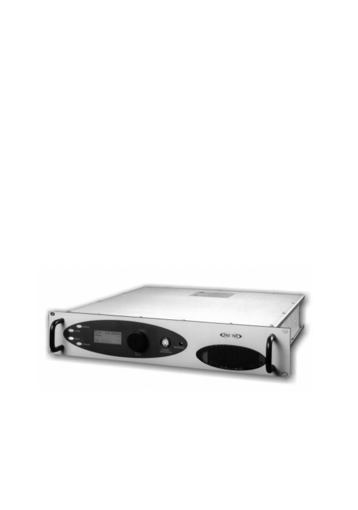
Park Air Electronics (PAE) T6R is a VHF multi-mode air traffic control receiver compatible with analogue
(AM) and digital (D8PSK) modulation modes. Current models are supplied programmed for AM voice
operation in the frequency range 118 to 136.975 MHz using 25 kHz or 8.33 kHz channel spacing. Future
software upgrades will allow D8PSK operation.
A multi-channel feature of the receiver allows up to 100 channels to be stored, and recalled by channel
number. Channel designation and all operational settings can be selected from the front panel, or by
using the virtual front panel (VFP), or through a compatible control and data system such as the PAE
multi-access remote control (MARC).
The receiver is designed to be fitted in an industrial 19 inch (483 mm) equipment rack. Operation is from
either a standard ac mains supply, or from a low voltage dc supply. When both input supplies are
connected, the dc supply acts as a back-up if the mains supply fails.
Comprehensive continuous and interruptive Built-In Tests (BIT) provide confidence of the receiver's
serviceability.
T6R HANDBOOKS
This user guide describes the T6R receiver and gives complete installation and setting up procedures.
The user guide is split into sections as follows:
Section 1. Section 1 (this section) provides general information that is common to all
operating modes.
Section 2. Section 2 provides information that is specific to operating the T6R receiver in
AM-voice mode.
Section 3. Section 3 onwards will, when available, describe the digital operating modes.
A maintenance kit (PAE part number 70-6100MKIT) is also available. A maintenance handbook,
included in the kit, contains fault finding guides to module level and details VFP operation. The VFP can
be used for setting up, maintenance purposes, and for loading new software.
The maintenance kit includes a CD-ROM containing the VFP software, and a lead for connecting the
radio to a Personal Computer (PC). The CD-ROM also contains the software as loaded into the T6R at
the time of sale. This enables the original software to be re-loaded if the receiver's Digital Signal
Processing (DSP) module is ever replaced.
Both the user guide and maintenance handbook are available on CD ROM. Contact PAE for details.
T6R General Information Section 1
Page 3
T6R receiver maintenance should not be attempted without reference
to the maintenance handbook
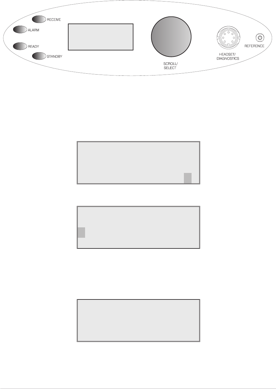
OPERATIONAL SETTINGS
Operational settings for the T6R receiver are configured at the front panel, through the VFP, or through
an associated MARC system (or compatible control and data system). At the receiver, operational
settings are selected and displayed using the front panel Scroll/Select switch and the LCD.
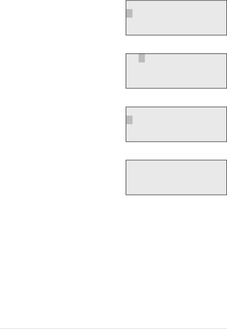
The settings are selected through a series of menus. Full details are given in the section of this user
guide applicable to the operating mode. Two example selection menus, Set Frequency menu and
Channel Storage menu, are shown below.
121 . 500MHz
Cance l OK
Ch100 121 . 500MHz
Cance l
Store
Store and End
During normal receiver operation, the Main screen, shown below, is displayed. The screen shows the
operating frequency, the channel number (if the channel store facility is used), and displays a graphical
representation of volume.
Freq 123 . 000MHz
Chan 1
Vol lllIIIIIIIII
Section 1 T6R General Information
Page 4
Freq 123.000MHz
Chan 1
Vol llllllllllll

Virtual Front Panel
As an alternative to setting up the receiver from the front panel, the T6R's virtual front panel (VFP)
software can be used. To use the VFP, an IBM™ compatible PC must be connected to the receiver (see
Fig. 1-1). Using the VFP offers several advatages over setting up from a receiver's front panel. These
are:
qWhen set up using the VFP, a profile of the receiver's operational settings can be created. The
profile can then be used to automatically set up other radios within a system, or to reset a radio
should the DSP module ever be replaced.
qAfter setting up from the VFP, the receiver's front panel can be locked. This means that a
receiver's settings cannot inadvertently be changed by tampering with the front panel controls.
qA print-out of a receiver's profile (all the operational settings) can be made from the VFP.
Instructions on VFP usage is outside the scope of this user guide. Reference, therefore, should be made
to the T6R maintenance kit that includes a CD-ROM containing the VFP software.
BUILT-IN TESTS
The receiver continuously self monitors key internal parameters without affecting normal operation. If a
BIT fault is detected, the front panel Alarm indicator lights, the Ready indicator becomes unlit, and the
receiver becomes inoperable.
Apart from continuous monitoring, an interruptive BIT test can be initiated locally at the front panel, or
remotely. When initiated, test signals are injected into the receiver's RF circuit allowing parameters to be
monitored in their active state.
The results of continuous monitoring, and of interruptive testing, are available at the front panel LCD.
When the receiver is used with a MARC system (or other compatible data and control system) the results
are also sent, in the form of a data message, to the monitoring facility. A full description of the BIT
facilities is given in the section of this user guide applicable to the operating mode. The following
illustration shows an example front panel BIT display.
Syn t h Lock PASS
Sens i t i v i t y PASS
Sens . - 107dBm
<< >>
T6R General Information Section 1
Page 5

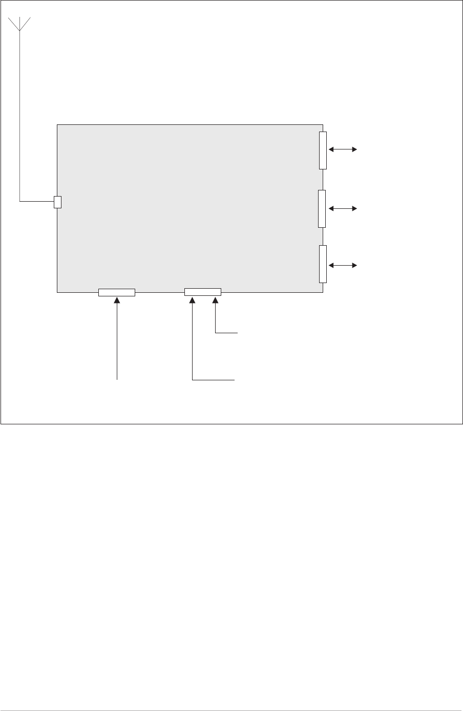
CONFIGURING THE T6R RECEIVER
Fig. 1-1 shows the signal connectors fitted to the receiver's front and rear panels. The connectors used to
configure the receiver depend on the required operating mode. The purpose of each connector is briefly
described in the following paragraphs and fully detailed in chapter 3.
Antenna Connector Used in all operating modes to connect the 50 ohm antenna feeder
cable.
Headset/Diagnostics
Connector
This is a dual purpose connector. A headset can be connected to enable
local AM-voice operation.
Alternatively, a PC can be connected to allow use of the VFP, to set the
receiver's operational settings, or to download new software.
Reference Connector Used in all operating modes to check and reset the receiver's reference
frequency.
Facilities Connector Used primarily to connect remote signals when using AM-voice mode
when the receiver does not form part of a MARC system.
Some auxiliary signals available at this connector, for example the
24 volt (nominal) unregulated output supply, can be utilized irrespective
of the operating mode.
MARC Port The MARC port is used to connect remote signals when the receiver
forms part of a MARC system, or other compatible control and data
system.
Computer Port The computer port is used in digital communication modes to connect
the receiver to a control computer.
Section 1 T6R General Information
Page 6
T6R General Information Section 1
Page 7
Fig. 1-1. T6R Receiver Configuration
Remote Signals.
Signals to/from a control
computer. Used when
operating in digital
communication modes.
Signals to/from an
RSE 2 equipment. Used
when the radio forms
part of a MARC system.
T6R Receiver
Antenna
Connector
Facilities
Connector
Computer
Port
MARC
Port
Headset for Local
AM Operation.
PC to allow use of the VFP
and to download new
software.
Frequency Counter for
maintenance purposes.
Headset/Diagnostics
Connector
Reference
Connector

Intentionally Blank
Section 1 T6R General Information
Page 8

Chapter 2. Specification
This chapter contains the T6R receiver's specification that is common to all operating modes.
Specifications relevant to specific operating modes are contained in the section applicable to the
required operating mode.
DIMENSIONS AND WEIGHT
The dimensions and weight of the T6R receiver are:
Width 483 mm (19 inches).
Height 88.9 mm (3.5 inches). The height occupies 2U of
equipment cabinet space.
Depth (front panel to rear panel) 430 mm (16.9 inches).
Weight 5.8 kg (12.8 pounds).
RF CHARACTERISTICS
Frequency range 118 to 136.975 MHz.
Number of channels The receiver has a multi-channel capability.
100 channels can be stored and recalled.
Frequency accuracy Better than 1 ppm.
Maximum RF input The receiver can withstand an input at the antenna
connector of:
5 V rms continuous.
15 V rms for 20 seconds.
Unwanted signal suppression The first and second IF image rejection is greater than
80 dB. For other frequencies, spurious signals are
suppressed by more than 100 dB.
ENVIRONMENTAL
Temperature range The receiver operates to specification at temperatures
between -20 and +55°C and at a relative humidity
between 5% and 90% (non-condensing).
Warm up time The receiver is fully operational 5 seconds after switch
on.
Storage The receiver can be stored at temperatures between -30
and +70°C without causing damage.
T6R General Information Section 1
Page 9

POWER REQUIREMENTS
The receiver operates from an ac input supply, or a dc input supply. When both supplies are connected,
the dc input acts as an automatic backup supply for the ac mains.
ac input supply The receiver operates from a 48 to 62 Hz single-phase
ac supply, and automatically adjusts to operate from any
supply voltage between 99 V ac and 264 V ac.
ac power consumption Typically 75 VA.
dc input supply Between 21.6 and 32 V.
dc supply current At 28 V current is typically 700 mA. 1 amp maximum.
Section 1 T6R General Information
Page 10
Chapter 3. Controls, Indicators, and Connectors
This chapter details the purpose of all controls, indicators, and connectors
fitted to the receiver's front and rear panels.
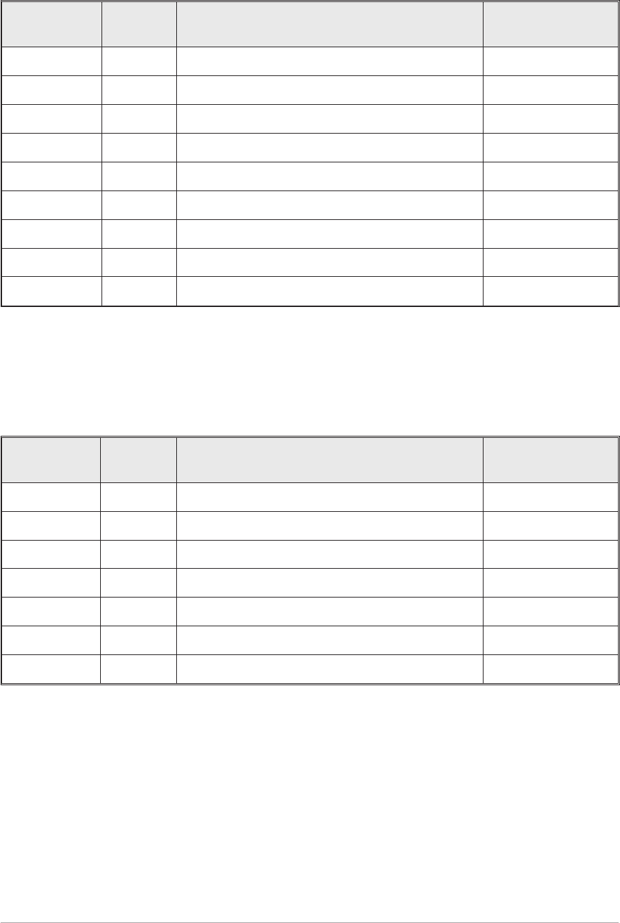
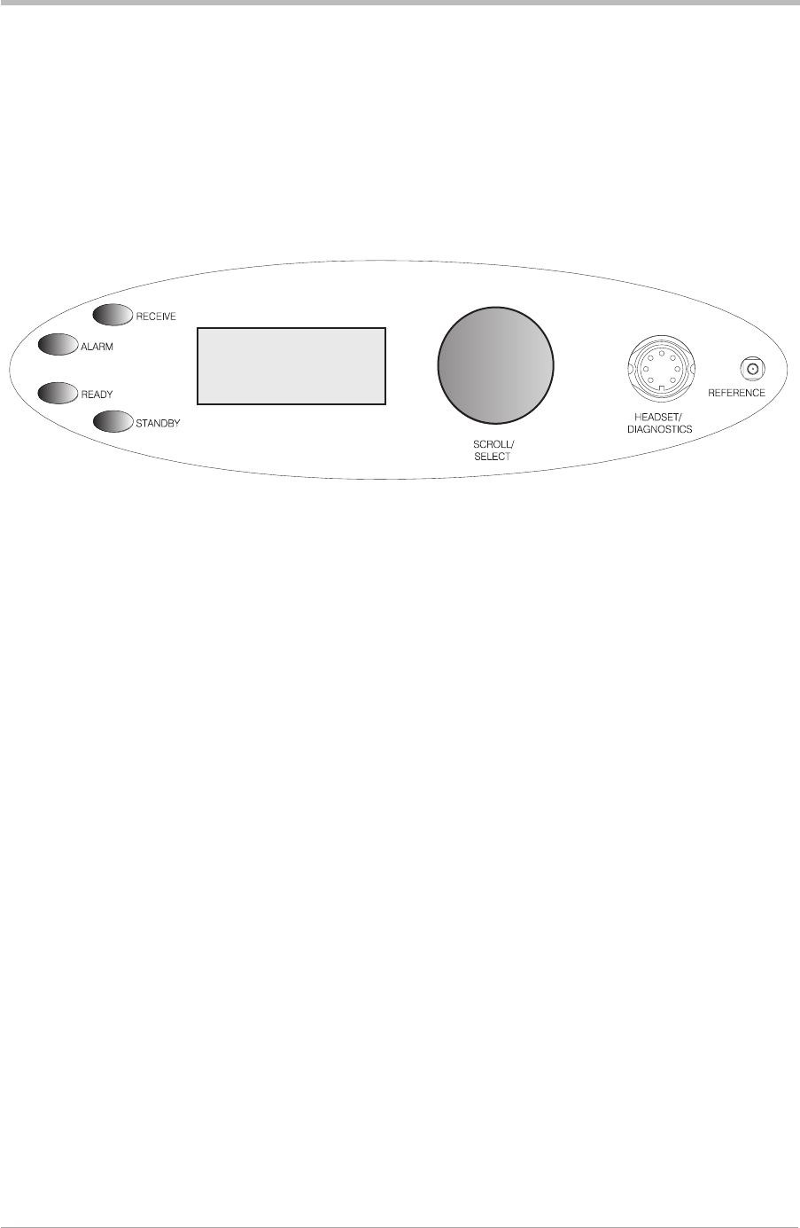
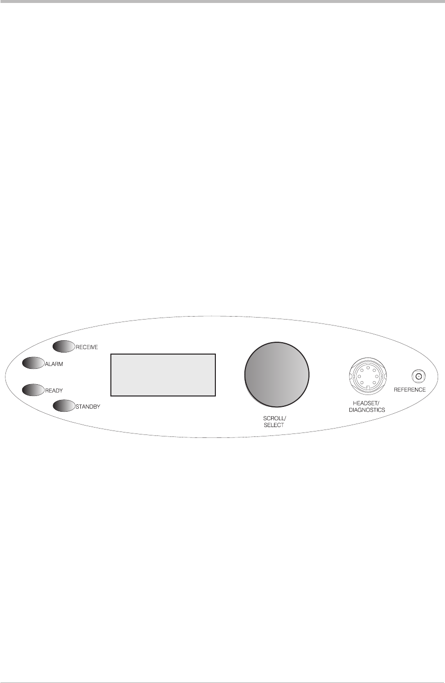
FRONT PANEL
The front panel's controls, indicators, and connectors are shown below and described in the following
paragraphs.
Receive Indicator
An amber indicator that lights when a signal is received that is above the squelch threshold. Additionally,
this indicator is lit when the receiver's squelch facility is switched off (squelch defeated).
Alarm Indicator
A red indicator that either lights, or flashes, when a BIT fault has been detected. BIT indications are
classified as either warnings or faults.
When a fault is detected, the Alarm indicator lights and the Ready indicator becomes unlit; the receiver
cannot be used.
If a warning is detected, the Alarm indicator flashes, the Ready indicator remains lit, and the receiver
remains operational.
Ready Indicator
A green indicator that lights when the receiver is ready for use and no BIT faults have been detected.
Standby Indicator
A red indicator that lights when the receiver is in standby mode. When in standby mode, most of the
receiver's circuits are inactive, and the front panel LCD is blanked; the receiver is inoperable until
standby mode is deselected.
Standby mode is selected and deselected using the front panel Scroll/Select switch and LCD, by
initiating an instruction through a MARC system, or through the VFP. Details of front panel selection and
deselection are given in the section of this user guide applicable to the particular operating mode.
T6R General Information Section 1
Page 11
Freq 123.000MHz
Chan 1
Vol llllllllllll
Reference Connector
An SMB jack socket that allows a high impedance frequency counter to monitor the receiver's reference
frequency. This connector is used only for maintenance purposes. The instructions for checking and
adjusting the reference frequency are given in the T6R maintenance handbook.
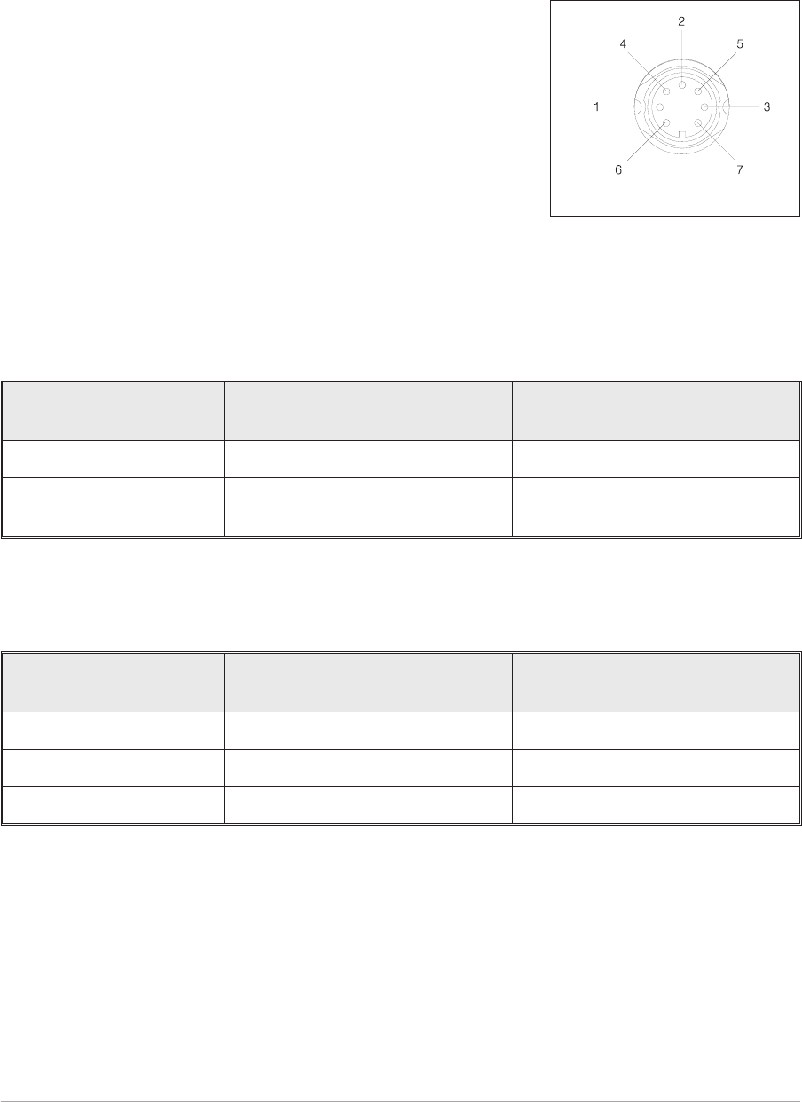
Headset/Diagnostics Connector
A dual purpose connector that allows either a headset or a PC to
be connected to the receiver. The connector is a 7-pin self
locking DIN socket.
A headset can be fitted to this connector to enable the receiver to
be operated in AM local mode. The connections are detailed in
Table 1-1. A PC can also be connected to allow the VFP to be
displayed. Using the VFP is detailed in the T6R maintenance
handbook. The connections at the receiver are shown in
table 1-2.
Table 1-1. Microphone/Headset Connections
Headset/Diagnostics
Connector Pin Number Signal Notes
1 Ground 0 volt.
5 Headset drive Maximum = 3 volt peak-to-peak.
200 ohm output impedance.
Table 1-2. Diagnostics PC Connections
Headset/Diagnostics
Connector Pin Number Signal Notes
2 Transmit data RS232
4 Receive data RS232
7 Ground 0 volt
Section 1 T6R General Information
Page 12
Fig. 1-2.
Headset/Diagnostics
Connector Pin-Out
(DEV083-05)

Scroll/Select Switch and LCD
The Scroll/Select switch is used in conjunction with the LCD to select most of the receiver's operational
settings. Use of the switch and LCD is fully detailed in the section of this user guide relevant to the
particular operating mode. During normal operation, the LCD shows the operating frequency, the
channel number (if the channel store facility is used) and displays a graphical representation of volume.
The example LCD screen below shows the receiver operating on 123.000 MHz; the frequency has been
preset as channel 8.
During normal receiver operation, when the main screen is displayed, the Scroll/Select switch acts as the
volume control.
Freq 123 . 000MHz
Chan 8
Vol llllIIIIIIII
T6R General Information Section 1
Page 13
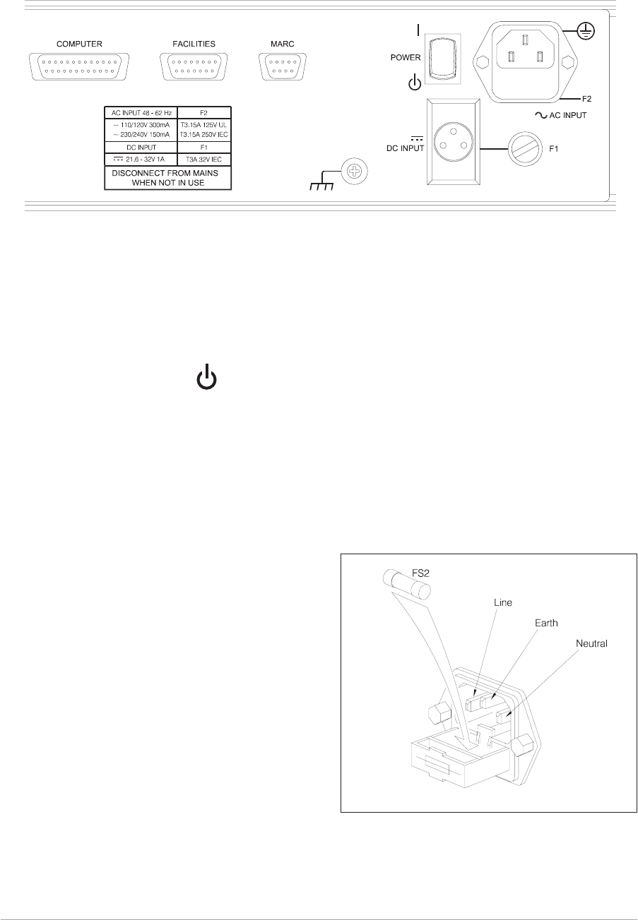
REAR PANEL
The rear panel's controls, indicators, and connectors are shown in Fig. 1-3 and described in the following
paragraphs.
Power Switch
A 2-way rocker switch used to switch on, and switch off, power to the receiver's circuitry.
l=On
WARNING!
When the POWER SWITCH is set to the Off position, lethal voltages are still present in the
receiver's internal power supply circuitry. To ensure safe working, the ac and dc input
supplies must be disconnected from the receiver.
AC Input Connector
A 3-pole IEC chassis plug for connecting the ac input
supply. The plug has an integral 20 mm fuse (F2) that
protects the Line (L) input circuit. The fuse is rated at
3.15 amps (see page 22 for further detail). Detailed
instructions for connecting the ac supply are given in
the installation chapter on page 24.
Section 1 T6R General Information
Page 14
= Off
Fig. 1-4. AC Connector
(SA3536)
Fig. 1-3. Rear Panel
DEV083-11a
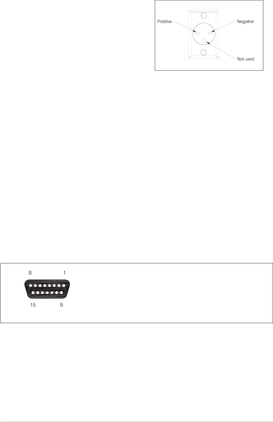
DC Input Connector
Fuse F1
Fuse F1 protects the dc input positive supply circuit. It is a size 0 fuse rated at 3 amps. The PAE part
number of the fuse is: 29-11100202.
Chassis Stud Connection
The chassis stud is used to provide a common earth point between the receiver and the associated
equipment rack, or the receiver and the user's system earth. The stud must not be used as a safety
earth. Connection details are given on page 24.
Facilities Connector CN5
A 15-way D-type socket used primarily to connect remote signals when the receiver operates in
AM-mode and does not form part of a MARC (or similar) system.The pin-out of this connector is given in
table 1-3 on page 17.
Apart from allowing connection of remote signals, this connector makes some auxiliary signals available
to the user. For example, a 24 volt (nominal) unregulated output supply. The auxiliary signals can be
employed by the user as and when required, irrespective of the operating mode.
T6R General Information Section 1
Page 15
Facilities connector CN5 as seen when looking at the rear panel.
Connections should be made using a 15-way D-type plug PAE part
number: 20-01150100 (plug), and 20-09150101 (cover). These are
supplied with the receiver as Item 3 (see page 22).
Fig. 1-6. Facilities Connector CN5 Pin-Out
(DEV083-06)
Fig. 1-5. DC Connector
A 3-pole chassis plug for connecting the dc input
supply. Detailed instructions for connecting the dc
supply are given in the installation chapter of this
handbook on page 25.
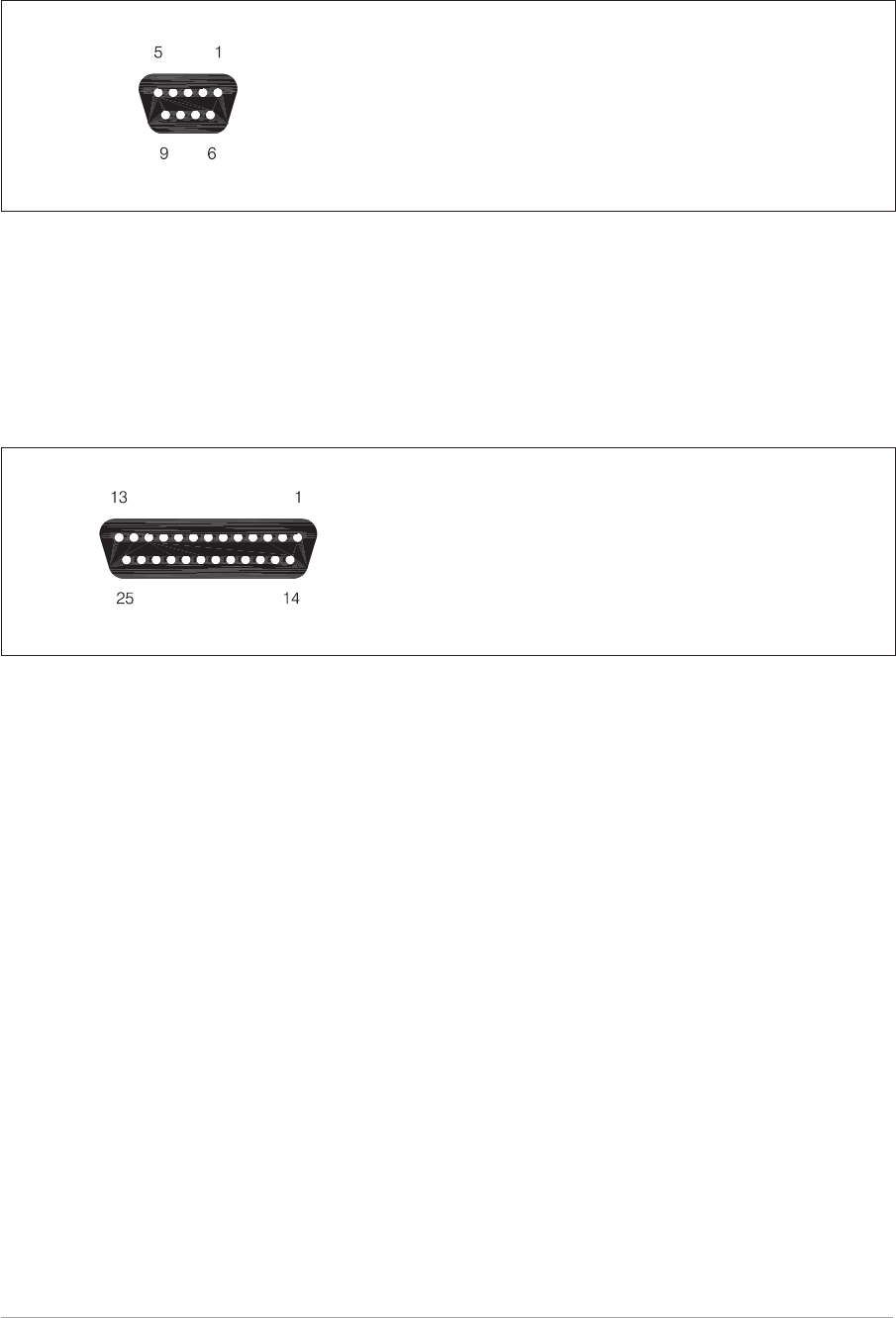
MARC Port CN6
A 9-way D-type socket used to connect remote signals to a MARC system or other compatible control
and data system. The pin-out of this connector is given in table 1-4 on page 18.
Computer Port CN7
A 25-way D-type socket used to connect the receiver to a control computer when the receiver is operated
in digital communication modes. The pin-out of this connector is given in table 1-5 on page 19.
Antenna Connector
An N-type 50 ohm coaxial socket used to connect the antenna's feeder cable.
Section 1 T6R General Information
Page 16
Fig. 1-7 MARC Port CN6 Pin-Out
MARC connector CN6 as seen when looking at the rear panel.
Connections should be made using a 9-way D-type plug PAE part
number: 20-01090100 (plug), and 20-09090101 (cover).
Fig. 1-8 Computer Port CN7 Pin-Out
Computer port CN7 as seen when looking at the rear panel.
Connections should be made using a 25-way D-type plug PAE part
number: 20-01250100 (plug), and 20-09250101 (cover).

Table 1-3. Facilities Connector CN5 Pin-Out
Pin
Number Signal Name Description
1 Ground 0 volt
2
3
Line Out (+)
Line Out (-)
Pins 2 and 3 are a 600 ohm balanced audio output. The output
level is adjustable between -30 and 0 dBm.
4 Squelch Defeat
An input signal to the receiver that, when active, disables the
receiver's squelch circuits. This is a TTL input pulled-up to 5 V.
The active polarity is set from the front panel.
5
6
Squelch Relay Common
Squelch Relay Output
Pins 5 and 6 are a relay circuit that operates when a signal,
above the squelch threshold, is received. This circuit can
switch voltages in the range -50 to +50 V (100 mA maximum)
and can be configured, at the front panel, to be normally open
or normally closed. Note that the configuration follows the
polarity of the squelch indication signal (see table 2-5 on
page 28 of section 2 for more detail).
7 Squelch Indication
This grounding output, when active, indicates a signal above the
squelch threshold is being received. The active polarity is set
from the front panel.
8 Ground 0 volt
9 Unregulated Supply A dc output supply between 21.6 and 32 volt (nominally
24 volt). The supply is fused at 500 mA.
10 Rx Disable
An input signal that, when active, disables the receiver's audio
output. When a receiver is configured with an associated transmitter
to form a base station, this signal can be used to disable the
receiver's audio output when the transmitter is keyed. This is a TTL
input pulled-up to 5 V. The active polarity is set from the front panel.
11 BIT Interruptive Test
An input signal that initiates a BIT interruptive test. This is a TTL
input pulled-up to 5 V. The active polarity of this signal is set
from the front panel. The input signal must be active for a
minimum of 300 ms; the signal cannot then be activated again
for at least 3 seconds.
12 RSSI
An analogue Receiver Signal Strength Indication that varies
between 0 volt and 10 volt. For a received signal of 1 µV the output
is less than 2 volts. For a received signal of 100 µV the output is
greater than 6 volts. The output impedance is 10 ohm. RSSI can be
used to provide relative indications when two receivers are
configured as a main and standby pair, when using receiver voting,
or when associated transmitter field strength monitoring is required.
13 Ready Output
This output is active when the radio is ready to receive and no
faults have been detected by the BIT circuitry. It is a grounding
output. The active polarity is set from the front panel.
14 Tape Output An audio output for connection to a recording system. The
output is nominally -10 dBm into 100 ohm.
15 Not Used -
T6R General Information Section 1
Page 17

Table 1-4. MARC Connector CN6 Pin-Out
Pin
Number Signal Name Description
1 Ground 0 volt.
2 Line Out (+) Pins 2 and 3 are a 600 ohm balanced audio output. The
output level is adjustable between -30 and 0 dBm.
3 Line Out (-)
4 Squelch Indication
This output, when active, indicates a signal above the
squelch threshold is being received. The active polarity is
set from the front panel.
5 Unregulated Supply
A dc output supply between 21.6 and 32 volt. The supply,
which is fused at 500 mA, is used as the power source for
the MARC RSE 2 equipment.
6 Data In (+) RS422 data line.
7 Data In (-) RS422 data line.
8 Data Out (+) RS422 data line.
9 Data Out (-) RS422 data line.
Section 1 T6R General Information
Page 18

Table 1-5. Computer Port CN7 Pin-Out
CN7 Pin Number Signal Name Level Input or Output
1 Ground 0 volt
2 Serial 0 TXA RS422 Output
3 Serial 0 TXB RS422 Output
4 Serial 0 RXA RS422 Input
5 Serial 0 RXB RS422 Input
6 Serial 0 CLA RS422 Output
7 Serial 0 CLB RS422 Output
8 Serial 1 TXA RS422 Output
9 Serial 1 TXB RS422 Output
10 Serial 1 RXA RS422 Input
11 Serial 1 RXB RS422 Input
12 Serial 1 CLA RS422 Output
13 Serial 1 CLB RS422 Output
14 Input A RS 232 Input
15 Input B RS232 Input
16 Input C RS232 Input
17 Input D RS232 Input
18 Output A RS232 Output
19 Output B RS232 Output
20 Output C RS232 Output
21 Output D RS232 Output
22 Ground 0 volt -
23 Not used - -
24 Not used - -
25 Not used - -
T6R General Information Section 1
Page 19

Intentionally Blank
Section 1 T6R General Information
Page 20

Chapter 4. Installation Procedures
This chapter details the installation procedures for a T6R receiver that are necessary irrespective of
which operating mode is to be used.
WARNING. LETHAL VOLTAGES!
The instructions given in this chapter involve connecting lethal voltages to the
receiver. The instructions detailed in this chapter must be carried out only by suitably
qualified personnel.
WARNING. UNAUTHORIZED MODIFICATIONS!
Changes or modifications made to this equipment that are not expressly approved by
Park Air Electronics, or parties authorized by Park Air Electronics, could void the user’s
authority to operate the equipment.
CAUTION. ESSDs!
The T6R receiver's circuitry contains Electrostatic Sensitive Devices (ESSDs).
Personnel must be aware of the precautions necessary to prevent damage to such
devices. During installation all precautions necessary to prevent ESSD damage must be
taken.
INTRODUCTION
The procedures in this chapter describe how to install a T6R receiver. The procedures necessary during
installation are listed in table 1-6 and should be completed in the order shown.
Table 1-6 Installation Procedures
Procedure Reference
1 Perform an initial inspection of the receiver. Page 22
2 Fit the correct ac input fuse. Page 22
3 Fit the receiver into an equipment rack. Page 23
4 Connecting remote facilities. Page 23
5 Connect the chassis stud to the rack or system earth. Page 24
6 Connect the ac input supply (if applicable). Page 24
7 Connect the dc input supply (if applicable). Page 25
8 Connect an antenna. Page 25
T6R General Information Section 1
Page 21

INITIAL INSPECTION OF THE RECEIVER
On receipt of the receiver from PAE, remove all transit packaging and check that there is no transit
damage. If damage is evident, contact PAE immediately and retain the original transit packaging.
The following items should be included with the receiver:
Item 1. One copy of the T6R user guide (this handbook).
Item 2. An unterminated IEC mains connector.
Item 3. An unterminated 15-way D-type plug (for use with the rear panel Facilities
connector CN5).
FITTING THE CORRECT AC INPUT FUSE
The mains input fuse F2 is an integral part of the rear panel ac connector (the connector and fuse are
shown in Fig. 1-4 on page 14). The fuse type must be correct for the local mains supply. Check the fuse
fitted conforms to that detailed in table 1-7.
Table 1-7 Input AC Fuse Rating
Mains Input Supply Fuse PAE Part Number
110/120 V T3.15A UL 29-01470102S
220/230/240 V T3.15A 250 V IEC 127 HBC 29C01100102S
Section 1 T6R General Information
Page 22
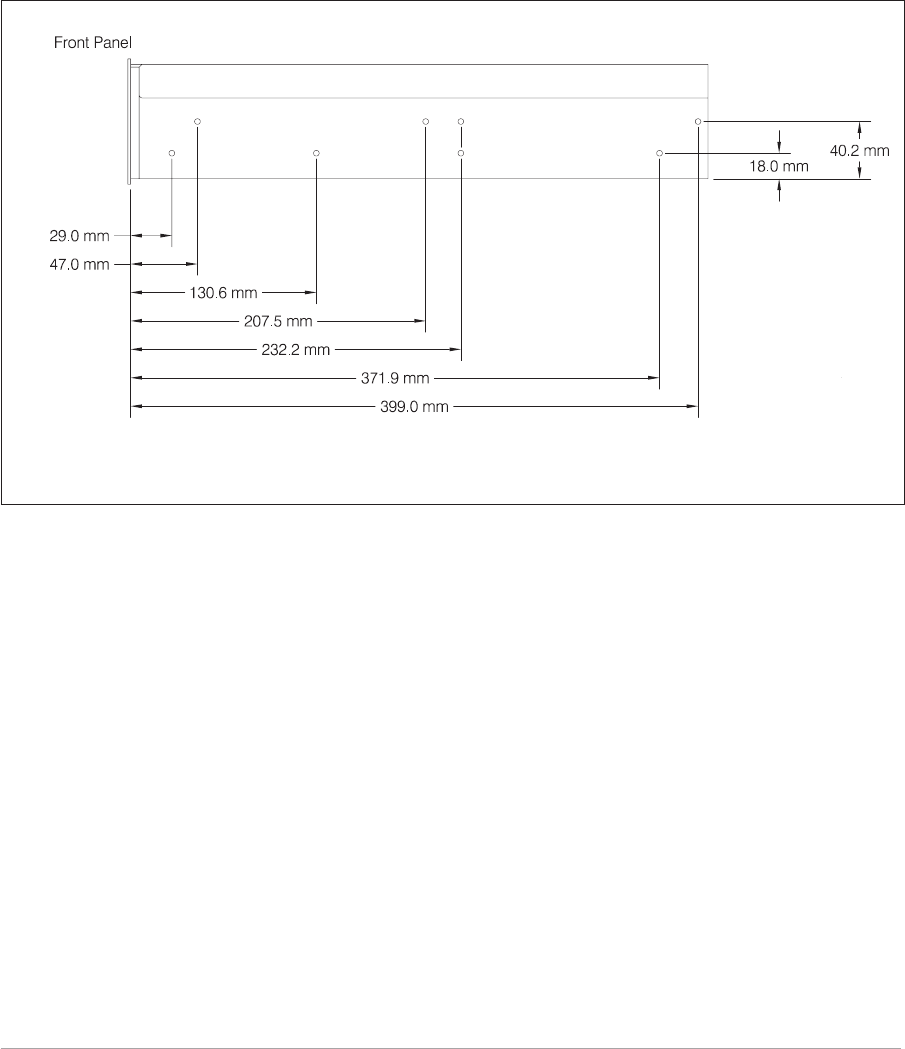
FITTING A RADIO INTO AN EQUIPMENT RACK
CAUTION!
It is essential that the chosen mechanical installation provides adequate support along
the depth (front to rear) of the unit. The receiver must not be supported by the front
panel; doing so can cause damage.
The receiver can be installed on telescopic slides, or on fixed runners, within a standard 483 mm
(19 inch) equipment rack. M4 tapped holes, each 10 mm deep (see Fig. 1-9) are provided on each side of
the equipment to accept the slides. Details of suitable telescopic slides and fixed runners are available
from PAE.
When fitted in the rack, the receiver's front panel must be secured to the racks chassis using four
M6 x 16 mm screws and plastic washers.
CONNECTING REMOTE FACILITIES
Remote facilities connections depend on the receiver's operating mode. To determine the required
remote connections, refer to chapter 3 of the section applicable to the operating mode.
T6R General Information Section 1
Page 23
Fig. 1-9. Telescopic Slide Fixing Points
(DEV083-24)

CHASSIS STUD CONNECTION
WARNING. CHASSIS EARTH!
A chassis stud is fitted to the receiver's rear panel. This stud is used to connect the
equipment to the equipment rack, or to the user's system earth point. The stud must not
be used as the safety earth.
In order not to compromise the receiver’s Electromagnetic Compatibility (EMC) the chassis stud, marked
and fitted to the rear panel (see Fig. 1-3 on page 14) must be connected to the equipment rack (if a
rack is being used) or to the user's system earth point. The connection should be made using a single
tri-rated, green-and-yellow cable having a cross-sectional area of 2.5 mm2. The cable should have CSA
and UL1015 approval, and be connected to the chassis stud through an M6 eyelet (for example, PAE
part number 20-08010103).
Failure to comply with this instruction could result in non-compliance with the European
Commission EMC Directive 89/336/EEC.
AC SUPPLY CONNECTION
WARNING. LETHAL VOLTAGES!
The equipment is permanently connected to the mains supply when the mains
connector is attached. Switching the rear panel Power switch to off does not isolate all
internal circuits from the mains supply. For this reason, a mains isolating switch should
be fitted close to, and easily accessible from, the receiver's position.
WARNING. EARTH CONNECTION!
This equipment must be earthed. The earth terminal of the AC connector should be used
as the safety earth.
An ac input connector (see Fig. 1-4 on page 14) is fitted to the equipment’s rear panel. The cable used to
connect between the equipment and the user’s ac power source should be 3-core (to IEC 227) rated
250 V ac at 8 amps, and have a minimum cross-sectional area of 1.0 mm² per core. PAE recommends
the use of polyvinyl chloride (PVC) insulated cable. The cable must be fitted with the IEC approved
equipment connector (PAE part number 20-02030102) supplied with the receiver, and conform to the
following specification:
qIf PVC insulated, be not lighter than ordinary polyvinyl chloride sheathed flexible cord
according to IEC publication 227 (designation H05 VV-F, or H05 VVH2-F).
qIf rubber insulated, be of synthetic rubber and not lighter than ordinary tough rubber-sheathed
flexible cord according to IEC publication 245 titled ‘Rubber Insulated Cables of Rated
Voltages up to and Including 450/750 V (designation H05 RR-F)’.
The T6R receiver is a Class 1 equipment. The ac supply cable should have a green-and-yellow
protective earthing conductor electrically connected to the protective earthing terminal of the equipment
connector and the mains plug. PAE recommends the ac supply cable is colour coded in accordance with
the electrical appliance (colour code) regulations for the UK. That is:
qThe core that is coloured green-and-yellow must be connected to the terminal in the plug that
is marked with the letter E or by the earth symbol or coloured green-and-yellow.
qThe core that is coloured blue must be connected to the terminal that is marked with the letter
N or coloured black.
qThe core that is coloured brown must be connected to the terminal that is marked with the
letter L or coloured red.
Section 1 T6R General Information
Page 24

DC SUPPLY CONNECTION
The receiver operates from either an ac, or a dc input supply. When both ac and dc are connected,
operation from the ac supply takes priority; automatic change-over to the dc supply occurs if the ac
supply fails. On restoration of the ac supply, the equipment reverts to ac operation.
A dc input supply connector (see Fig. 1-5 on page 15) is fitted to the equipment's rear panel. The
recommended minimum rating of the dc supply cable is: 2-core having a cross-sectional area of 1.5 mm2
per core. The supply cable should be fitted with an XLR3 connector (PAE part number 20-01030106).
CONNECTING AN ANTENNA
The antenna feeder cable connects to the receiver’s rear panel N-type antenna connector (see Fig. 1-3
on page 14).
SWITCHING ON
When the installation is complete, the receiver should be switched on at the rear panel Power switch (see
page 14).
T6R General Information Section 1
Page 25

Intentionally Blank
Section 1 T6R General Information
Page 26

T6R Receiver User Guide
Section 2
AM-Voice Mode
T6R AM-Voice Mode Section 2
Page 1

Section 2 T6R AM-Voice Mode
Page 2
Page
Section 2 Contents
Chapter 1. AM-Voice Mode Overview
Introduction to AM-voice mode 3
Operational Settings 3
Basic Configuration 4
Local Operation 4
Remote Operation 4
Configuration for Operation with MARC 6
Chapter 2. Specification
RF Characteristics 7
Modulation Characteristics 7
Chapter 3. Installation
Introduction 9
Connecting the Remote Facilities 10
Connecting to MARC Equipment 10
Chapter 4. Operational Settings
Introduction 13
Normal Operation 13
Using the Scroll/Select Switch 13
Screen Protocol 14
Menu Lock Screen 16
Notes for Setting Up the Receiver 17
Front Panel Display for 25 kHz and 8.33 kHz Channel Spacing 17
Line Level Setting 18
To Enter and Exit Standby Mode 19
To Enter Standby Mode 19
To Exit Standby Mode 20
AM-Voice Settings Procedure 21
General Receiver Settings 25
Selecting the Operating Frequency 29
Allocating channel numbers to specified frequencies 30
To Store Channel Frequencies 30
To Recall Channel Frequencies 31
To initiate an interruptive bit test 32
To View BIT Pages and advise screen 33
Elapsed time indicator 34
displaying the receiver's internal reference frequency screen 35
Software versions screen 36

Chapter 1. AM-Voice Mode Overview
This chapter provides an introduction to using the T6R receiver in AM-voice mode.
INTRODUCTION TO AM-VOICE MODE
In AM-voice mode the T6R receiver operates in the frequency range 118 to 136.975 MHz using 25 kHz
or 8.33 kHz channel spacing. An internal loudspeaker, or headphones plugged into the front panel,
allows the receiver to be used in local mode. Alternatively, rear panel connectors provide the interfaces
for remote operation.
The majority of operational settings can be selected from the front panel, or through a compatible control
and data system such as the PAE multi-access remote control (MARC). A multi-channel feature of the
receiver allows up to 100 frequency channels to be stored and recalled by channel number.
OPERATIONAL SETTINGS
Operational settings for the T6R receiver are configured at the front panel, through the VFP, or through
an associated MARC system (or compatible control and data system). At the receiver, operational
settings are selected and displayed using the front panel Scroll/Select switch and the LCD. The settings
that can be selected are:
qOperating frequency qSelecting front panel frequency step size
qChannel allocation and recall qSetting the line level
qSetting the squelch level qSetting squelch defeat to on or off
qSetting audio AGC to on or off qSetting the loudspeaker volume
qSetting the LCD backlight qSetting receiver disable on or off
qSetting the MARC baud rate qSetting squelch indication signal polarity
qSetting the disable signal polarity qSetting the squelch defeat polarity
qSetting the BIT initiate signal polarity qSetting the ready out signal polarity
qSetting standby mode to on or off
T6R AM-Voice Mode Section 2
Page 3

BASIC CONFIGURATION
Fig. 2-1 shows the basic T6R receiver connections for AM-voice operation. If the receiver is part of a
MARC system, or other compatible control and data system, refer to ‘Configuration for Operation with
MARC’ on page 6.
Local Operation
In its simplest configuration, the receiver can be operated in local mode. This involves using the built-in
loudspeaker, or connecting a headset to the front panel Headset/Diagnostics connector. All operational
settings are then selected using the Scroll/Select switch.
Remote Operation
For remote operation signals are connected from the receiver's rear panel Facilities connector, through a
suitable communication link, to the control equipment. Essential connections are the receiver's audio
output and a squelch indication (a choice of squelch indication signals are available). Other remote
signals can be connected to suit the particular application. The remote signals are fully described in
section 1 on page 17.
In the basic configuration, the rear panel MARC and Computer Port connectors are not used. The front
panel Reference connector is used to check the receiver's internal reference frequency during
scheduled maintenance. The front panel Headset/Diagnostics connector is used to connect a PC for
maintenance purposes, or to use the VFP.
Maintenance using a PC connected to the Headset/Diagnostics connector is outside the scope of this
user guide. Full information is contained in the T6R maintenance handbook.
Section 2 T6R AM-Voice Mode
Page 4
T6R AM-Voice Mode Section 2
Page 5
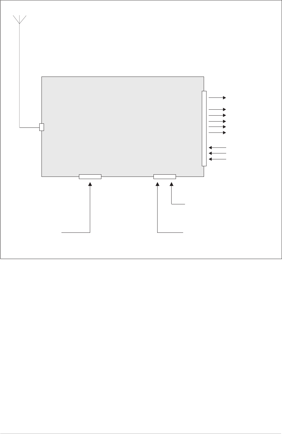
Fig. 2-1. T6R Receiver - Basic Configuration
T6R Receiver
Antenna
Connector Facilities
Connector
Headset for local operation
PC for maintenance
purposes
Frequency Counter for
maintenance purposes
Audio
Squelch Indications
Unregulated Supply
RSSI
Ready Indication
Tape Output
Squelch Defeat Signal
Rx Disable
BIT Interruptive Test
Remote Signals
Headset/Diagnostics
Connector
Reference
Connector
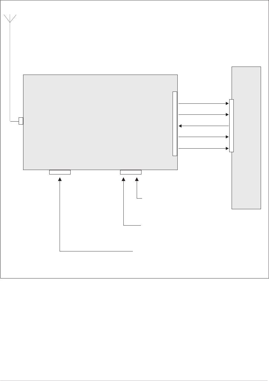
CONFIGURATION FOR OPERATION WITH MARC
When the T6R receiver is used with a MARC system or other compatible control and data system, the
remote signals are connected through the rear panel MARC connector (see Fig. 2-2). In this
configuration, the rear panel Facilities and Computer Port connectors are not used unless some auxiliary
signals available at the Facilities connector are required.
Section 2 T6R AM-Voice Mode
Page 6
T6R Receiver
Fig. 2-2. T6R Receiver - Configuration for Use with MARC
MARC
Connector
Headset/Diagnostics
Connector
Reference
Connector
Antenna
Connector
Audio
Squelch Indication
Control Information
Status Information
Unregulated Supply
MARC
RSE 2
RSE 2
has 8
equipment
connectors
allowing up
to 8 radios
to be
connected
Equipment
Connector
Headset
for Engineering Use
PC for maintenance
purposes
Frequency Counter for
maintenance purposes

Chapter 2. Specification
This chapter gives the receiver's specification applicable to AM-voice operation.
RF CHARACTERISTICS
Channel spacing 25 kHz, or 8.33 kHz across the frequency band 118 to
136.975 MHz.
Sensitivity Better than 1 µV PD (-107 dBm) for 10 dB (S+N)/N, or
12 dB SINAD ratio; both with ITU-T recommendation
P.53 weighting.
IF selectivity For 25 kHz channel spacing:
At ± 11 kHz from the centre frequency, the signal is
not attenuated by more than 6 dB.
At ± 25 kHz from the centre frequency the signal is
attenuated by more than 80 dB.
For 8.33 kHz channel spacing:
At ± 3.5 kHz from the centre frequency, the signal is
not attenuated by more than 6 dB.
At ± 8.33 kHz from the centre frequency, the signal
is attenuated by more than 70 dB.
At ± 25 kHz from the centre frequency, the signal is
attenuated by more than 80 dB.
MODULATION CHARACTERISTICS
Frequency response For 25 kHz channel spacing, the variation in frequency
response with reference to a 1 kHz signal, is within
+2 dB, -3 dB across the frequency range 300 to
3400 Hz. The response is better than -10 dB at 100 Hz,
and better than -30 dB at 5 kHz.
For 8.33 kHz channel spacing, the variation in frequency
response, with reference to a 1 kHz signal, is within
+2 dB, -3 dB across the frequency range 350 to
2500 Hz. The response is better than -10 dB at 100 Hz,
and better than -30 dB at 5 kHz.
Hum and noise With a -47 dBm RF input, the receiver's hum and noise
is more than 45 dB below the signal level for a carrier
modulated by a 1 kHz signal with a modulation index of
0.9.
T6R AM-Voice Mode Section 2
Page 7

Distortion For RF input signals between -47 dBm and +10 dBm,
the total harmonic distortion is less than 5% due to
signals with a modulation index of 0.8 and within the
frequency range 300 Hz to 3400 Hz.
AGC For received signals between -107 dBm and +10 dBm
there is less than 3 dB change in audio output. The AGC
attack time is less than 15 ms and the decay time is less
than 50 ms.
Squelch The receiver has a noise compensated carrier operated
squelch with an adjustment range of -114 to -60 dBm,
and provides greater than 60 dB of quieting.
Attack time is <50 ms for a signal rising 10 dB above the
squelch setting.
Release time is <50 ms for a signal falling 10 dB below
the squelch setting.
Hysteresis 2 to 4 dB.
Level control An audio AGC ensures there is less than 1 dB change in
audio output level when the modulation index is
increased from m = 0.3 to m = 0.9.
The audio AGC can be switched off from the front panel,
through MARC, or the VFP.
Section 2 T6R AM-Voice Mode
Page 8

Chapter 3. Installation
This chapter details the installation procedures that are applicable only to AM-voice operation.
WARNING. LETHAL VOLTAGES!
The instructions given in this chapter involve connecting lethal voltages to the
receiver. The instructions detailed in this chapter must be carried out only by suitably
qualified personnel.
WARNING. UNAUTHORIZED MODIFICATIONS!
Changes or modifications made to this equipment that are not expressly approved by
Park Air Electronics, or parties authorized by Park Air Electronics, could void the user’s
authority to operate the equipment.
CAUTION. ESSDs!
The T6R receiver's circuitry contains Electrostatic Sensitive Devices (ESSDs).
Personnel must be aware of the precautions necessary to prevent damage to such
devices. During installation all precautions necessary to prevent ESSD damage must be
taken.
INTRODUCTION
The procedures in this chapter that allow a T6R receiver to be installed for AM-voice operation are:
qConnecting remote facilities in non-MARC applications
qConnecting remote facilities to a MARC (or a compatible control and data system).
T6R AM-Voice Mode Section 2
Page 9

CONNECTING THE REMOTE FACILITIES
If the receiver is being used in the ‘Basic Configuration’ (see Fig. 2-1 on page 5) remote signals are
terminated on the rear panel Facilities connector CN5. For configurations where the T6R receiver is
being used with a MARC system, or other compatible data and control system, this procedure should be
ignored; instead, refer to ‘Connecting to MARC Equipment’.
The remote facilities available at CN5 are listed in section 1 on page 17. Essential connections, unless
the receiver is being used only in local mode, are the audio output (pins 2 and 3) and, usually, a squelch
indication output.
Make any other connections to CN5 as required.
When making connections to the Facilities connector CN5, and in order not to compromise the receiver's
Electromagnetic Compatibility (EMC) users must:
qUse a D-type connector that has a screened cover
qUse screened multi-way cable, with the cable's screen connected to the Facilities connector's
shell or body.
Failure to comply with this instruction could result in non-compliance with
the European Commission EMC Directive 89/336/EEC
CONNECTING TO MARC EQUIPMENT
If the receiver is being used with a MARC system, or compatible control and data system, remote
connections are made through the rear panel MARC connector CN6 (see Fig. 2-2 on page 6).
The pin-out of CN6 is shown in section 1 on page 18. If connecting to a MARC RSE 2 equipment, the
connections between CN6 and one of RSE 2's Equipment Connectors is pin-to-pin as shown in table 2-1.
When making connections to the Facilities connector CN6, and in order not to compromise the receiver's
Electromagnetic Compatibility (EMC) users must:
qUse a D-type connector that has a screened cover
qUse screened multi-way cable, with the cable's screen connected to the Facilities connector's
shell or body.
Failure to comply with this instruction could result in non-compliance with
the European Commission EMC Directive 89/336/EEC
Section 2 T6R AM-Voice Mode
Page 10

Table 2-1 MARC Connector CN6 to RSE 2 Equipment Connector
T6R Receiver RSE 2 Equipment Connector
Pin
Number Signal Name Pin
Number Signal Name
1 Ground 1 0 Volt
2 Line Out(+) 2 Audio Line L1
3 Line Out (-) 3 Audio Line L2
4 Squelch Indication 4 Mute
5 Unregulated Supply 5 Unregulated Supply Input
6 Data In (+) 6 Data Out (+)
7 Data In (-) 7 Data Out (-)
8 Data Out (+) 8 Data In (+)
9 Data Out (-) 9 Data In (-)
Note ...
The squelch indication signal from the receiver connects to the RSE 2's mute connection.
T6R AM-Voice Mode Section 2
Page 11

Intentionally Blank
Section 2 T6R AM-Voice Mode
Page 12
Chapter 4. Operational Settings
This chapter details how the T6R receiver is set up for AM-Voice operation from the front panel.
It also details how to set the receiver in and out of standby mode.
The receiver can also be set up through a MARC system, or by using the VFP. Both of
these methods are outside the scope of this handbook; users should refer to the MARC
User Guide and the T6R Maintenance Handbook.
INTRODUCTION
Selecting most of the receiver's operational settings is carried out using the front panel Scroll/Select
switch and the LCD (see the illustration below). Table 2-2 on page 15 shows a list of the operational
settings. No attempt to set up the receiver should be made until it has been installed as per the
Installation Procedures given in section 1 of this user guide.
Normal Operation
During normal operation, the LCD displays the Main screen. This screen shows the operating frequency,
the channel number (if the channel store facility is used) and displays a graphical representation of
volume. The receiver's loudspeaker and headset volume can be adjusted by rotating the Scroll/Select
switch. If the receiver has been set to Standby mode, which is shown by the front panel STANDBY
indicator being lit, the LCD is blanked.
Using the Scroll/Select Switch
The SCROLL/SELECT switch (referred to throughout this chapter as the ‘Switch’) is used to exit the
Main screen and display the Options menu. Further use of the Switch displays various selection menus
and allows the required parameters to be set. The switch has three actions: it can be turned clockwise,
anti-clockwise, or momentarily pushed in.
Note that during normal receiver operation, the Scroll/Select switch acts as a volume control.
T6R AM-Voice Mode Section 2
Page 13
Freq 123.000MHz
Chan 1
Vol llllllllllll

SCREEN PROTOCOL
The following protocol is applicable to all screens described in this chapter.
Main Screen During normal receiver operation, the Main screen, an example of which is
shown below, is displayed.
Freq 123 . 000MHz
Chan 1
Vol lllIIIIIIIII
Switch Refers to the front panel Scroll/Select switch. The switch is turned clockwise to
scroll through fields from left to right, and from top to bottom. The switch is
turned anti-clockwise to scroll through fields from right to left, and from bottom
to top. The switch is pressed to make a selection.
Timeout If during any setting up procedure the Scroll/Select switch is not operated for
30 seconds, the display returns to the Main screen. If editing any parameter
has not been completed, the receiver stays on the original setting.
>> Indicates more fields are available other than those currently displayed. To
access those fields, turn the switch clockwise through the last displayed field.
<< Indicates more fields are available other than those currently displayed. To
access those fields, turn the switch anti-clockwise through the first displayed
field.
Back When Back is selected, you are returned to the previous menu.
Exit When Exit is selected, you are returned to the Main screen.
Section 2 T6R AM-Voice Mode
Page 14

Table 2-2 Operational Settings
Parameter Adjustment Range Factory
Default Setting
Further
Reference
Menu lock screen Locked or unlocked Unlocked Page 16
To enter Standby mode On or Off Off Page 19
To exit Standby mode - - Page 20
Set mode of operation AM-voice AM-voice
Part of ‘AM
Voice Settings
Procedure’
starting
on page 21.
Squelch level -60 dBm to -114 dBm -107 dBm
Squelch defeat On or Off Off
Audio AGC On or off On
Front panel frequency step size 8.33, 25 kHz, or both 25 kHz
Loudspeaker volume 0 to 100%, or Off 30%
LCD backlight timeout 15 s to 120 s, Off, or On 30 s
Part of ‘General
Receiver
Settings
Procedure’
starting
on page 25.
Receiver disable On or off Off
Line level -30 dBm and 0 dBm -13 dBm
MARC port baud rate 300 to 9600 baud 9600 baud
Squelch output signal polarity Positive or Negative Pos
Disable input signal polarity Positive or Negative Pos
Squelch defeat input signal polarity Positive or Negative Pos
BIT initiate input signal polarity Positive or Negative Pos
Ready output signal polarity Positive or Negative Pos
Selecting the operating
frequency 118.000 to 136.975 MHz 118.00 MHz Page 29
Store frequency channels 1 to 100 - Page 30
Recall frequency channels 1 to 100 - Page 31
Initiate a BIT test - - Page 32
View BIT pages and advise screens - - Page 33
Elapsed time indication - - Page 34
Display internal reference
frequency screen - - Page 35
Software versions - - Page 36
T6R AM-Voice Mode Section 2
Page 15

MENU LOCK SCREEN
A security facility available only from the VFP allows the receiver's front panel to be ‘locked’. When this
facility is active, no operational settings can be made from the front panel until an ‘unlock’
command is sent from the VFP.
The following screen is displayed when ‘lock’ is active, and the front panel switch is pressed.
S ECUR I TY MESSAG E
SystemLocked
OK
To exit the system lock screen:
qTurn the switch to highlight OK, then press the switch. You are returned to the main screen.
or,
qWait for the 30 second timeout to expire. You are returned to the main screen.
Section 2 T6R AM-Voice Mode
Page 16

NOTES FOR SETTING UP THE RECEIVER
The following notes should be read before setting up the receiver. They advise on the special frequency
display when using 8.33 kHz channel spacing, and give guidance on the optimum line level.
Front Panel Display for 25 kHz and 8.33 kHz Channel Spacing
When setting the operating frequency of the receiver and 8.33 kHz channel spacing is selected, the
displayed frequency differs from the actual channel frequency. Table 2-3 shows the pattern used for
25 kHz and 8.33 kHz spaced channel frequencies from 118.000 MHz to 118.1916 MHz. The pattern is
the same for any frequency within the receiver's frequency range. The display conforms to ICAO
convention for 8.33 kHz operation.
Table 2-3 25 kHz and 8.33 kHz Channel Spacing Displays
Actual Frequency
(to 4 decimal places)
Channel
Spacing
Displayed Frequency
at Receiver's Front Panel
118.0000 MHz
118.0000 MHz
118.0083 MHz
118.0166 MHz
118.0250 MHz
118.0250 MHz
118.0333 MHz
118.0416 MHz
118.0500 MHz
118.0500 MHz
118.0583 MHz
118.0666 MHz
118.0750 MHz
118.0750 MHz
118.0833 MHz
118.0916 MHz
118.1000 MHz
118.1000 MHz
118.1083 MHz
118.1166 MHz
118.1250 MHz
118.1250 MHz
118.1333 MHz
118.1416 MHz
118.1500 MHz
118.1500 MHz
118.1583 MHz
118.1666 MHz
118.1750 MHz
118.1750 MHz
118.1833 MHz
118.1916 MHz
25 kHz
8.33 kHz
8.33 kHz
8.33 kHz
25 kHz
8.33 kHz
8.33 kHz
8.33 kHz
25 kHz
8.33 kHz
8.33 kHz
8.33 kHz
25 kHz
8.33 kHz
8.33 kHz
8.33 kHz
25 kHz
8.33 kHz
8.33 kHz
8.33 kHz
25 kHz
8.33 kHz
8.33 kHz
8.33 kHz
25 kHz
8.33 kHz
8.33 kHz
8.33 kHz
25 kHz
8.33 kHz
8.33 kHz
8.33 kHz
118.000 MHz
118.005 MHz
118.010 MHz
118.015 MHz
118.025 MHz
118.030 MHz
118.035 MHz
118.040 MHz
118.050 MHz
118.055 MHz
118.060 MHz
118.065 MHz
118.075 MHz
118.080 MHz
118.085 MHz
118.090 MHz
118.100 MHz
118.105 MHz
118.110 MHz
118.115 MHz
118.125 MHz
118.130 MHz
118.135 MHz
118.140 MHz
118.150 MHz
118.155 MHz
118.160 MHz
118.165 MHz
118.175 MHz
118.180 MHz
118.185 MHz
118.190 MHz
T6R AM-Voice Mode Section 2
Page 17

Line Level Setting
The line level setting displayed on the front panel is equivalent to the average speech level with a
peak-to-average ratio of 13 dB. This corresponds to the level specified for the lines.
When testing the receiver using a signal generator with sine wave modulation, the line output level will be
10 dB above the line level setting.
Table 2-4 Relationship between Line Level, Output Levels with Average Speech
and Sine Wave
Line Level Setting
(Front Panel Setting)
(dBm)
Output Level with
Average Speech
(dBm)
Output Level with
Sine Wave
(dBm)
0 0 +10
-5 -5 +5
-10 -10 0
-15 -15 -5
-20 -20 -10
-25 -25 -15
-30 -30 -20
Section 2 T6R AM-Voice Mode
Page 18

TO ENTER AND EXIT STANDBY MODE
Standby mode is a power saving feature that can be used for non-operational receivers. When in
standby mode, most of the receiver's circuits are inactive, the LCD is blanked, and there is no audio
output.
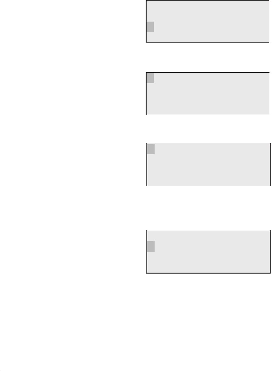
To Enter Standby Mode
To put the receiver into standby mode, use the following procedure.
1. From the Main screen, press the switch to
display the Options menu. Ensure that
Configure is highlighted. Press the switch.
2. Ensure the Configure menu is displayed.
Turn the switch until Standby is highlighted,
then press the switch.
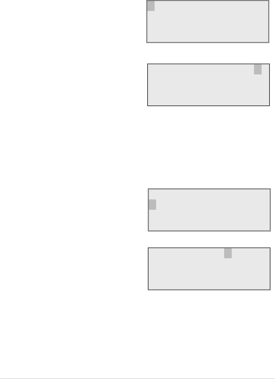
3. Check that the Standby menu is displayed.
Turn the switch until Yes is highlighted, then
press the switch. [To abandon this
procedure, select No instead of Yes and
then press the switch.]
4. Check that the LCD blanks, and the front panel STANDBY indicator lights.
5. The receiver is now in standby mode. To exit standby, see the next procedure.
T6R AM-Voice Mode Section 2
Page 19
Frequency
Channe l
Con f i gu r e
BIT Exi t
Se t t i ngs
S/W Versions
St andby
Back Ex i t
Put radio into
St andby mode ?
YES NO

To Exit Standby Mode
Standby mode is indicated by the front panel STANDBY indicator being lit and the LCD being blanked.
To exit this mode, use the following procedure.
1. Press the switch and check that the Exit
menu is displayed.
2. Turn the switch until YES is highlighted,
then press the switch. [To abandon this
procedure, select No instead of Yes and
then press the switch.]
3. Check that the Main screen is displayed and that the front panel STANDBY indicator is unlit.
4. The receiver is now ready for normal use.
Section 2 T6R AM-Voice Mode
Page 20
Ex i t St andby
Mod e
YES NO
Freq 123 . 000MHz
Vo l llllllllllll
AM-VOICE SETTINGS PROCEDURE
During this procedure, the following parameters, applicable to AM-voice operation, will be set:
qMode of operation qSquelch level
qSquelch defeat on or off qAudio AGC on or off
qFront panel frequency step size qLoudspeaker volume
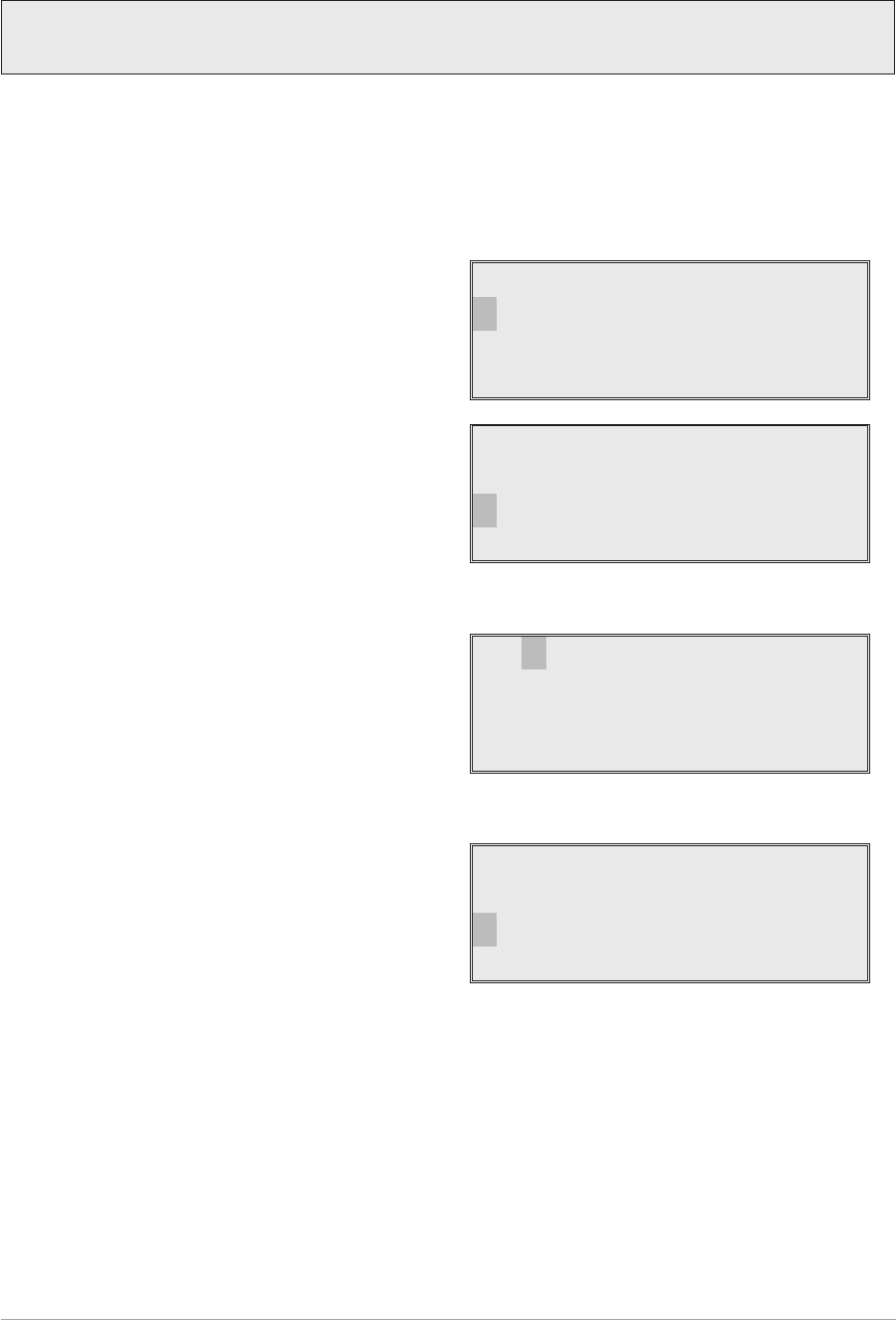
1. From the Main screen, press the switch to
display the Options menu. Turn the switch
until Configure is highlighted. Press the
switch.
2. Ensure the Configure menu is displayed.
Turn the switch until Settings is highlighted,
then press the switch.
3. Check that the Function menu is displayed
and turn the switch until Mode is highlighted.
Press the switch.
4. Selecting AM-Voice Operation.
Check that AM Voice is displayed. If any
other mode is displayed, press the switch
until AM Voice is shown.
Turn the switch clockwise until Settings is
highlighted. Then press the switch to display
the mode specific Settings menu.
T6R AM-Voice Mode Section 2
Page 21
Frequency
Channe l
Con f i gu r e
BIT Exi t
Options Menu
Mod e
Reference Freq
Display
>>
Function Menu
Se t t i ngs
S/W Versions
St andby
Back Ex i t
Configure Menu
Mod e : AM Vo i c e
Se t t i ngs
Cance l OK

5. Setting the Squelch Level.
[Factory default setting: -107 dBm]
The receiver's squelch level can be set
between -60 dBm and -114 dBm.
To set the squelch level, ensure Squelch is
highlighted. Press the switch. Turn the switch
clockwise or anti-clockwise to increase or
decrease the value. When the required value
is displayed, press the switch. Turn the switch
clockwise to highlight Sql Defeat.
6. Setting Squelch Defeat to On or Off.
[Factory default setting: Off]
The receiver's squelch facility can be switched on or off.
Ensure that Sql Defeat is highlighted. Press
the switch to toggle between On and Off.
On = Squelch Defeated. The receiver's
squelch circuit does not operate and the front
panel Receive indicator stays lit.
Off = Squelch facility enabled. An audio output
is heard only when a signal greater than the squelch level is received.
When the required setting is highlighted, turn the switch clockwise to highlight Audio AGC.
7. Setting the Audio AGC.
[Factory default setting: On]
The receiver's Audio AGC facility can be
switched On or Off.
When set to on, the audio output level remains
constant for received signal modulation depths
greater than 30%.
When set to off, the audio output level is
proportional to the received signal modulation
depth.
To make the required setting, ensure Audio AGC is highlighted. Press the switch to toggle
between On and Off.
When the required setting is highlighted, turn the switch clockwise to highlight Channel Spacing.
Section 2 T6R AM-Voice Mode
Page 22
Squelch -107dBm
Sql Defeat OFF
Au d i o AGC ON
>>
Mode Specific Settings Menu
Squelch -107dBm
Sql Defeat OFF
Au d i o AGC ON
>>
Squelch -107dBm
Sql Defeat OFF
Au d i o AGC ON
>>

8. Setting the Front Panel Frequency Step Size.
[Factory default setting: 25 kHz]
The receiver's channel spacing can be 25 kHz, or 8.33 kHz. The radio automatically sets the
correct channel spacing for the frequency that is entered at the front panel. This setting, which is
only for the user's convenience, alters front panel frequency step size.
qIf all channels to be selected or stored are 25 kHz spaced channels, then 25 should be
selected.
qIf all channels to be selected or stored are 8.33 kHz spaced channels, then 8.3 should be
selected.
qIf a mixture of the two are required, both 25 and 8.3 should be selected.
To select the required spacing, ensure that
Channel Spacing is highlighted and press the
switch.
Check that the Channel Spacing menu is
displayed and that Spacing is highlighted.
Press the switch to change between 25 kHz,
8.3 kHz, and both. When the required value is
displayed, turn the switch to highlight OK, then
press the switch again. You will be returned to
the Mode Specific Settings menu.
T6R AM-Voice Mode Section 2
Page 23
Channe l Spac i ng
Loudspeaker
Back
Ex i t <<
Spac ing 25kHz
8.3kHz
Cance l OK
Channel Spacing Menu (Both Selected)

9. Setting the Loudspeaker/Headset Volume.
[Factory default setting: 30% Volume; Loudspeaker On]
The receiver's loudspeaker and headset volume can be set, and the speaker can be switched on
or off during this procedure.
Turn the switch clockwise until Loudspeaker is highlighted, then press the switch.
Ensure that the Loudspeaker menu is
displayed and that Volume is highlighted.
Press the switch. Turn the switch clockwise to
increase volume, or anti-clockwise to
decrease volume. When the required value
(0 to 100%) is displayed, press the switch.Turn
the switch clockwise until OK is highlighted,
then press the switch.
To turn the loudspeaker on and off, highlight
Speaker and press the switch to toggle
between On and Off. When the required
setting is displayed, turn the switch to highlight
OK, then press the switch. You are returned to
the Mode Specific Settings menu.
10. To exit the AM-Voice Settings Procedure, turn the switch to highlight Exit, then press the switch.
You are returned to the Main screen. When this procedure is complete, go to the General
Receiver Settings procedure starting on the next page.
Section 2 T6R AM-Voice Mode
Page 24
Volume 030%
Speaker ON
OK
Channe l Spac i ng
Loudspeaker
Back
Ex i t <<

GENERAL RECEIVER SETTINGS
During this procedure, the following parameters will be set:
qLCD backlight qDisable on or off
qLine level qMARC baud rate
qSquelch output signal polarity qDisable input signal polarity
qSquelch defeat polarity qBIT initiate signal polarity
qReady output signal polarity
1. From the Main screen, press the switch to
display the Options menu. Turn the switch
until Configure is highlighted. Press the
switch.
2. Ensure the Configure menu is displayed.
Turn the switch until Settings is highlighted,
then press the switch.
3. Setting the LCD Backlight.
[Factory default setting: 30 s]
Check that the Settings menu is displayed
and turn the switch until Display is
highlighted. Press the switch.
The LCD's backlight can be set to off,
permanently on, or timed to stay on for a
period between 15 and 120 seconds
(adjustable in 15 second steps) after the
Scroll/Select switch was last operated.
Ensure the Backlight menu is displayed and
Backlight is highlighted. Press the switch.
Turn the switch until the required setting is
displayed, then press the switch. Turn the
switch clockwise until OK is highlighted, then
press the switch. You are returned to the
Settings menu.
T6R AM-Voice Mode Section 2
Page 25
Frequency
Channe l
Con f i gu r e
BIT Exi t
Options Menu
Se t t i ngs
S/W Versions
St andby
Back Ex i t
Configure Menu
Mod e
Reference Freq
Display
>>
Settings Menu
Back l i ght 030s
Cance l OK
4. Setting Disable On or Off.
[Factory default setting: Off]
Receiver disable can be set to either On or Off. When set to on, the receiver's audio output is
disabled. When set to off, audio is available through the internal loudspeaker, the headset, or
through the remote audio lines.
From the Settings menu, turn the switch
clockwise until Disable is highlighted, then
press the switch.
Check that the Disable menu is displayed and
Disable is highlighted. Pressing the switch
toggles between On and Off. When the correct
setting is displayed turn the switch clockwise
to highlight OK, then press the switch. You are
returned to the Settings menu.
5. Setting the Line Level.
[Factory default setting: -13 dBm]
The audio line output level can be set to any value between -30 dBm and 0 dBm. Some notes
regarding the optimum line level are given on page 18.
From the Settings menu, turn the switch
clockwise until Line Level is highlighted, then
press the switch.
Check that the Line Level menu is displayed
and that Line Lvl is highlighted, then press the
switch.
Turn the switch clockwise or anti-clockwise to
increase or decrease the value. When the
required value is displayed, press the switch.
Turn the switch to highlight OK and then press
the switch. You are returned to the Settings menu.
Section 2 T6R AM-Voice Mode
Page 26
Disable
Line Level
MARC
<< >>
Disable ON
Cance l OK
Disable
Line Level
MARC
<< >>
Line Lvl -13dBm
Cance l OK

6. Setting the MARC Baud Rate.
[Factory default setting: 9600]
The baud rate must be set when the T6R receiver is connected to a MARC system (or other
compatible data and control system). The rate can be set to 300, 600, 1200, 2400, 4800, or 9600
baud.
From the Settings menu, turn the switch
clockwise until MARC is highlighted, then
press the switch.
Ensure that the MARC menu is displayed
and that Baud Rate is highlighted.
Press the switch. Turn the switch until the
required value is displayed, then press the
switch. Turn the switch clockwise until OK is
highlighted, then press the switch. You are
returned to the Settings menu.
7. Polarity Settings.
The polarity of the following input and output signals is set using the Polarity menu:
qSquelch output signal
qDisable input signal
qSquelch defeat input signal
qBIT initiate input signal
qReady output signal.
To establish the required polarity for the input and output signals, refer to table 2-5.
From the Settings menu, turn the switch until
Polarity is highlighted. Then press the switch
to display the Polarity menu.
To set the required polarity, turn the switch to
highlight the required parameter, then press
the switch to toggle between NEG and POS.
When all polarities have been set, highlight
Back, and press the switch to return to the
Settings menu.
T6R AM-Voice Mode Section 2
Page 27
Baud Rate 9600
Cance l OK
Disable
Line Level
MARC
<< >>
Disable NEG
Squelch Out POS
Squelch Def NEG
>>
BIT Ini t NEG
Ready Out POS
Back
Ex i t <<
Polarity Menu
Polarity
Back
Ex i t
<<

Table 2-5 Signal Polarities
Signal Description State when Polarity is
set to NEG
State when Polarity is
set to POS
Squelch
This grounding output,
when active, indicates a
signal above the squelch
threshold is being
received.
Output is 0 V during no
signal condition, and high
impedance when a signal
is received.
Output is high impedance
during no signal condition,
and 0 V when a signal is
received.
Disable
An input signal that, when
active, disables the
receiver's audio output.
This is a TTL input
pulled-up to 5 V.
A 5 V input disables the
receiver.
A 0 V input disables the
receiver.
Squelch
defeat
An input signal to the
receiver that, when active,
disables the receiver's
squelch circuits. This is a
TTL input pulled-up to 5 V.
A 5 V input defeats the
squelch function.
A 0 V input defeats the
squelch function.
BIT initiate
An input signal that
initiates a BIT interruptive
test. This is a TTL input
pulled-up to 5 V. The input
signal must be active for a
minimum of 300 ms; the
signal cannot then be
activated again for at least
3 seconds.
A 5 volt input initiates a
BIT test.
A 0 volt input initiates a
BIT test.
Ready output
This output is active when
the radio is ready for use
and no faults have been
detected by the BIT
circuitry. It is a grounding
output.
Output is a high
impedance when the
receiver is ‘ready’, and
0 volt when not ‘ready’.
Output is 0 volt when the
receiver is ‘ready’, and a
high impedance when not
‘ready’.
Squelch
relay
The squelch relay circuit operates when a signal, above the squelch threshold, is
received. This circuit can switch voltages in the range -50 to +50 V (100 mA
maximum) and can be configured to be normally open or normally closed. The
configuration follows the polarity of the squelch indication signal as follows:
When the squelch indication polarity is POS, the squelch relay is configured as
normally open.
When the squelch indication polarity is NEG, the squelch relay is configured as
normally closed.
8. To exit the General Receiver Settings procedure, turn the switch to highlight Exit, then press the
switch. You are returned to the Main screen. When this procedure is complete, go to Setting the
Operating Frequency procedure starting on the next page.
Section 2 T6R AM-Voice Mode
Page 28

SELECTING THE OPERATING FREQUENCY
To set the receiver's operating frequency, use the following procedure. If a frequency is to be stored as
one of the 100 available preset channels, ignore this procedure and go to ‘Allocate Channel Numbers to
Specified Frequencies’ on page 30. Before setting the operating frequency, the required front panel
frequency step size should be set (see page 23).
1. From the Main screen, press the switch to
display the Options menu. Ensure that
Frequency is highlighted. Press the switch.
2. Ensure the Set Frequency menu is
displayed and that the MHz digits are
highlighted. Press the switch.
3. Turn the switch clockwise to increase frequency, or anti-clockwise to decrease frequency. The
MHz value increments/decrements in 1 MHz steps. Stop when the required value is shown. Press
the switch.
4. Turn the switch clockwise to highlight the kHz digits and press the switch. Turn the switch
clockwise to increase frequency, or anti-clockwise to decrease frequency (note that continuous
scrolling of the kHz value will increment or decrement the MHz value). Stop when the required
value is shown. Press the switch. Note that if 25 kHz channel spacing is selected, the kHz value
increments/decrements in 25 kHz steps; if 8.33 kHz channel spacing is selected, the kHz value
increments/decrements in the pattern detailed in ‘Table 2-3, 25 kHz and 8.33 kHz Channel
Spacing Displays’ on page 17. If both is selected, the display shows the 25 kHz and 8.33 kHz
channels.
5. Turn the switch clockwise until either Cancel or OK is highlighted. Then press the switch. If cancel
is selected, the new frequency entered in this procedure is ignored. If OK is selected, the receiver
operates on the new frequency.
T6R AM-Voice Mode Section 2
Page 29
Frequency
Channe l
Con f i gu r e
BIT Exi t
121 . 500MHz
Cance l OK
ALLOCATING CHANNEL NUMBERS TO SPECIFIED FREQUENCIES
Up to 100 frequency channels can be stored in the receiver. Use the following procedure to allocate
frequency channels.
To Store Channel Frequencies
Use the following procedure to allocate frequency channels.
1. From the Main screen, press the switch to
display the Options menu. Turn the switch
until Channel is highlighted. Press the
switch.
2. Ensure the Channel menu is displayed.
Turn the switch until Set is highlighted.
Press the switch.
3. Ensure the Channel screen is displayed and
turn the switch until the channel number is
highlighted. Press the switch, then turn the
switch until the required channel number is
displayed. When it is, press the switch.
4. Turn the switch to highlight the MHz value,
the press the switch. Turn the switch until
the required value is displayed, then press
the switch. Repeat for the kHz value.
5. When the correct frequency for the
displayed channel number is displayed, turn
the switch until Store is highlighted, then
press the switch.
6. Repeat steps 3 to 5 for all frequency channels that are to be stored. When the required number of
frequency channels have been stored, highlight Store and End and press the switch. You will be
returned to the Main screen.
Section 2 T6R AM-Voice Mode
Page 30
The process of allocating frequency channels can be simplified by using the VFP.
The VFP software is contained in the T6R receiver's maintenance kit.
Frequency
Channe l
Con f i gu r e
BIT Exi t
Ch007 123 . 450MHz
Reca l l
Se t
Back
Ch001 119 . 100MHz
Reca l l
Store
Store and End
Ch001 119 . 100MHz
Reca l l
Store
Store and End
To Recall Channel Frequencies
Frequency channels that have been stored in the receiver can be recalled by channel number as follows.
1. From the Main screen, press the switch to display
the Options menu. Turn the switch until Channel
is highlighted. Press the switch.
2. Ensure the Channel menu is displayed. Turn the
switch until the channel number is highlighted.
Press the switch. Turn the switch until the
required channel number is displayed. Then
press the switch.
3. Turn the switch until Recall is highlighted, then
press the switch.
4. The Main screen will then be displayed showing
the receiver's selected channel number and
corresponding operating frequency.
T6R AM-Voice Mode Section 2
Page 31
Frequency
Channe l
Con f i gu r e
BIT Exi t
Ch007 123 . 450MHz
Reca l l
Se t
Back
Ch007 123 . 450MHz
Reca l l
Se t
Back
Freq 123 . 450MHz
Chan 7
Pw r

TO INITIATE AN INTERRUPTIVE BIT TEST
Use the following procedure to initiate an interruptive BIT test from the receiver's front panel.
1. From the Main screen, press the switch to
display the Options menu. Turn the switch
until BIT is highlighted. Press the switch.
2. Ensure the BIT menu is displayed. Turn the
switch until BIT Initiate is highlighted, then
press the switch.
3. During the test, which takes approximately
two seconds, the Testing screen is
displayed.
4. When the test has finished, check that the
receiver's front panel Alarm indicator is not lit. After a BIT test, BIT screens are automatically
displayed. The screens are shown on the next page.
Section 2 T6R AM-Voice Mode
Page 32
Frequency
Channe l
Con f i gu r e
BIT Exi t
BIT Ini t iate
BIT View
ETI 00123:59
Back Ex i t
Test ing
Pl ease Wa i t
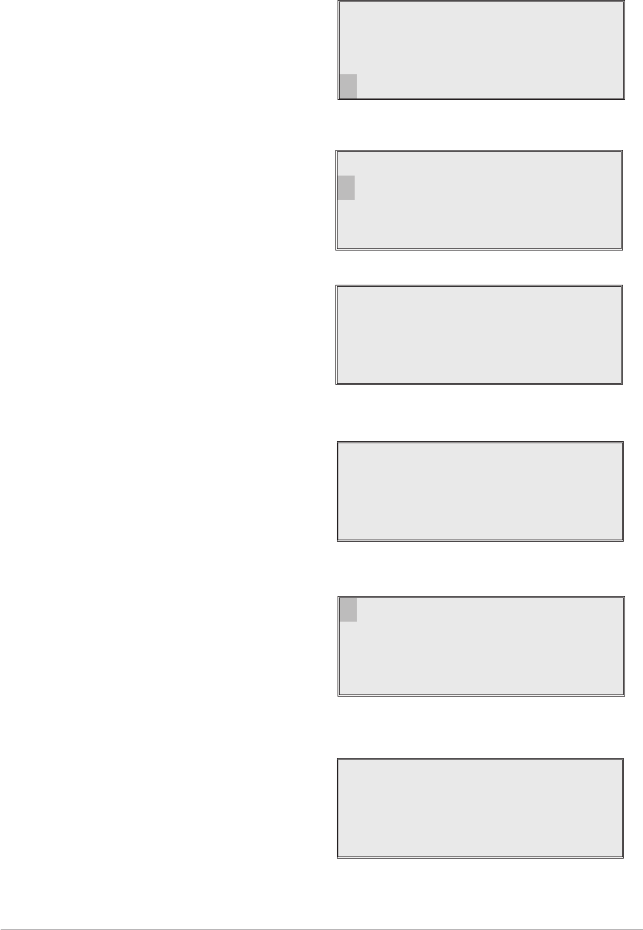
TO VIEW BIT PAGES AND ADVISE SCREEN
Use the following procedure to view the BIT page displays. Note that after a BIT interruptive test, the BIT
screens are automatically displayed.
1. From the Main screen, press the switch to
display the Options menu. Turn the switch
until BIT is highlighted. Press the switch.
2. Ensure the BIT menu is displayed. Turn the
switch until BIT View is highlighted, then
press the switch.
3. A series of pages is shown displaying
certain receiver parameters. Some
examples are shown here.
A full list of BIT screens along with
appropriate explanations is given in the
T6R receiver maintenance handbook.
4. Note that the last BIT screen allows Advise
to be highlighted and selected by pressing
the switch. If any BIT faults have been
detected, the advise screen recommends
the remedial action, in order of priority, to be
taken.
Further detail regarding the Advise screen
is given in the T6R receiver maintenance
handbook.
T6R AM-Voice Mode Section 2
Page 33
Frequency
Channe l
Con f i gu r e
BIT Exi t
BIT Ini t iate
BIT View
Back Ex i t
Syn t h Lock PASS
Sens i t i v i t y PASS
Sens . - 107dBm
<< >>
Example BIT Screen
AC Supp l y ON
DC Supp l y OFF
Supp l y 24V
>>
Example BIT Screen
Advise
Back
<<
Last BIT Screen
Pl ease Check
1 :RxRF
2:DSP
>>
Example Remedial Advise Screen

ELAPSED TIME INDICATOR
An elapsed time indicator (ETI) shows the number of hours the receiver has been powered up since
manufacture. To view the ETI:
1. From the Main screen, press the switch to
display the Options menu. Turn the switch
until BIT is highlighted. Press the switch.
2. ETI can be seen measured in hours and
minutes.
Section 2 T6R AM-Voice Mode
Page 34
Frequency
Channe l
Con f i gu r e
BIT Exi t
BIT Ini t iate
BIT View
ETI 00123:59
Back Ex i t
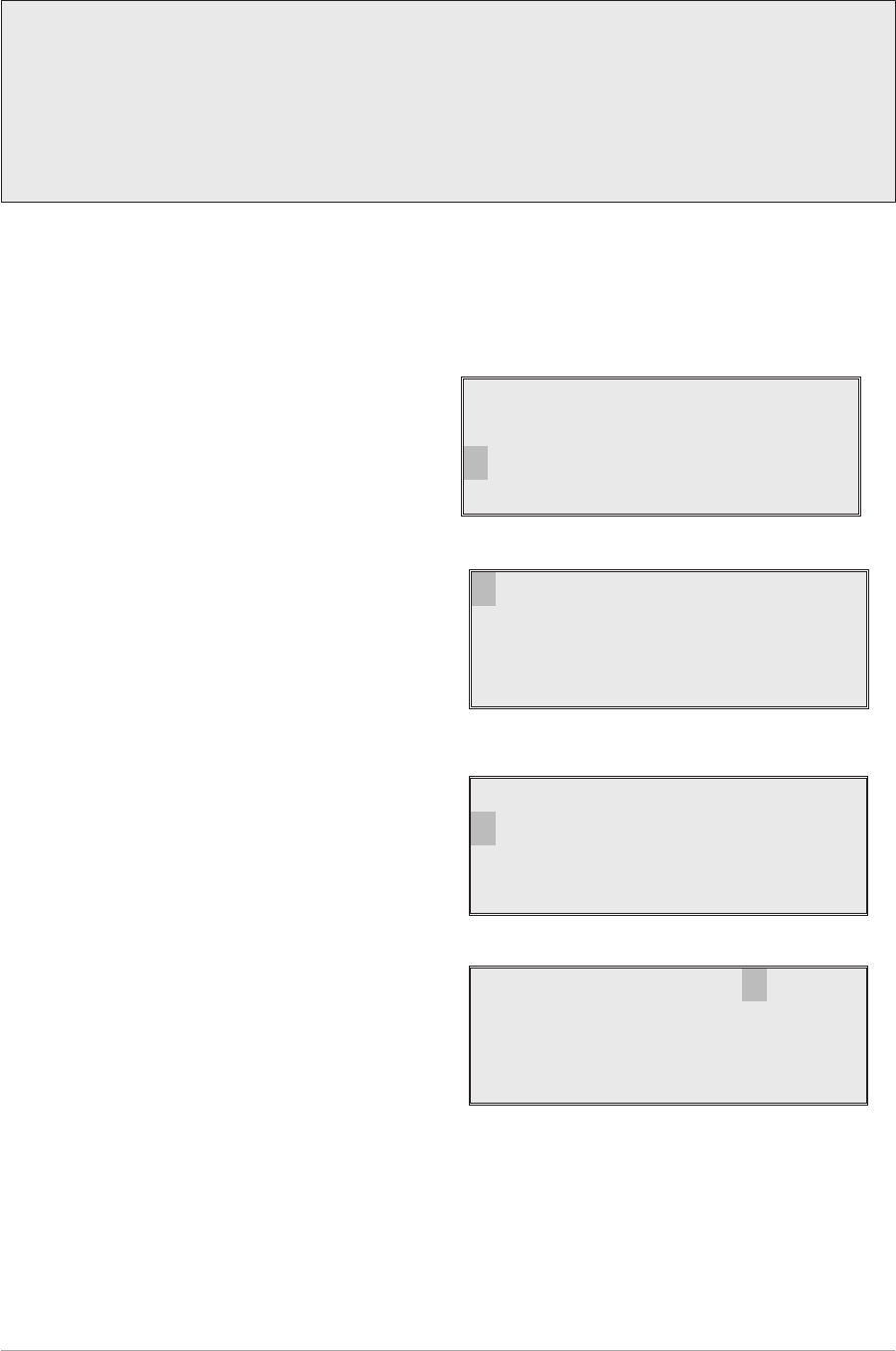
DISPLAYING THE RECEIVER'S INTERNAL REFERENCE FREQUENCY SCREEN
To display the receiver's internal reference frequency screen, use the following procedure.
1. From the Main screen, press the switch to
display the Options menu. Turn the switch
until Configure is highlighted. Press the
switch.
2. Ensure the Configure menu is displayed.
Turn the switch until Settings is highlighted,
then press the switch.
3. Check that the Function menu is displayed
and turn the switch until Reference Freq is
highlighted. Press the switch.
4. Ensure the Reference menu is displayed.
5. To exit the screen, wait for 30 seconds
when the display automatically reverts to
the Main screen, or select Cancel.
T6R AM-Voice Mode Section 2
Page 35
Caution!
This procedure is included only for informational purposes. The reference frequency setting
must not be altered unless following the procedure given in the T6R maintenance handbook.
External test equipment is required to set this parameter.
Failure to comply with this caution may render the receiver inoperable.
Frequency
Channe l
Con f i gu r e
BIT Exi t
Se t t i ngs
S/W Versions
St andby
Back Ex i t
Mod e
Reference Freq
Display
>>
Ref Freq 50.0%
Cance l OK

SOFTWARE VERSIONS SCREEN
The software versions screen allows the user to view the version of various software modules installed in
the receiver. To view the software versions, use the following procedure.
1. From the Main screen, press the switch to
display the Options menu. Ensure that
Configure is highlighted. Press the switch.
2. Ensure the Configure menu is displayed.
Turn the switch until S/W Versions is
highlighted, then press the switch.
3. Check the Software Versions screen is
displayed. Select Boot, Flash, or Fills and
press the switch to display the installed
version. The example shows the Boot
software.
4. Select OK, then press the switch to return to
the Software Versions screen. View the
other software modules as required.
Section 2 T6R AM-Voice Mode
Page 36
Frequency
Channe l
Con f i gu r e
BIT Exi t
Options Menu
Se t t i ngs
S/W Versions
St andby
Back Ex i t
Configure Menu
Boo t
Flash
Fills
Back Ex i t
Software Versions Screen
Boot Version
S0271V0001
OK
Boot Version Screen