Park Air Systems B63300HS VHF Ground to Air Transmitter User Manual 300W VHF Hardcopy
Park Air Systems Limited VHF Ground to Air Transmitter 300W VHF Hardcopy
Contents
- 1. user manual part 1
- 2. user manual part 2
user manual part 2

T6T 300 Watt VHF Transmitter Page 79 Installation
Configuring the Transmitter for Operational Use
The transmitter can be configured for use in several different ways. Typical configurations are illustrated
in the following figures:
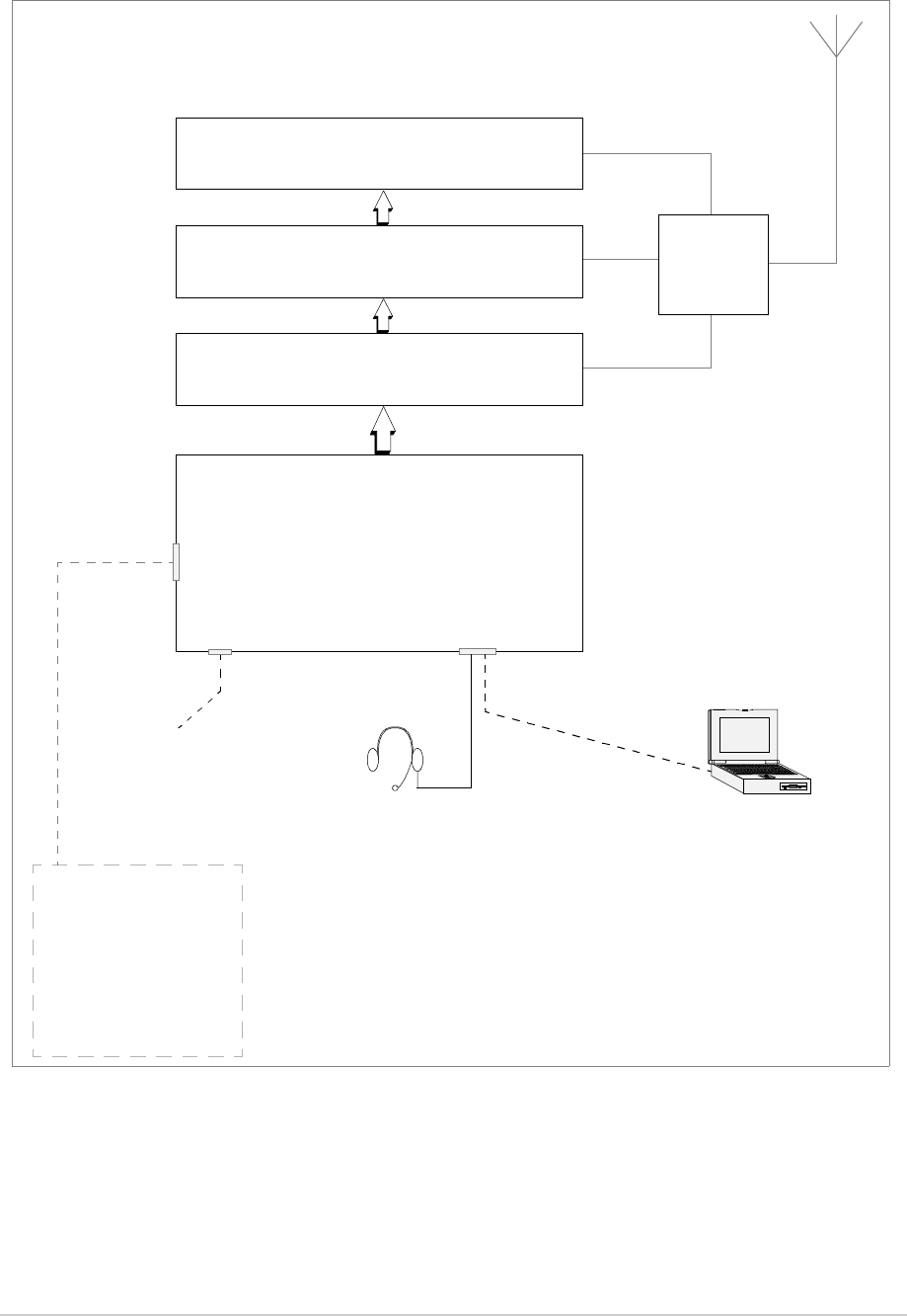
Fig 19 Local operation. Operating the transmitter using a microphone connected to the drive
assembly front panel.
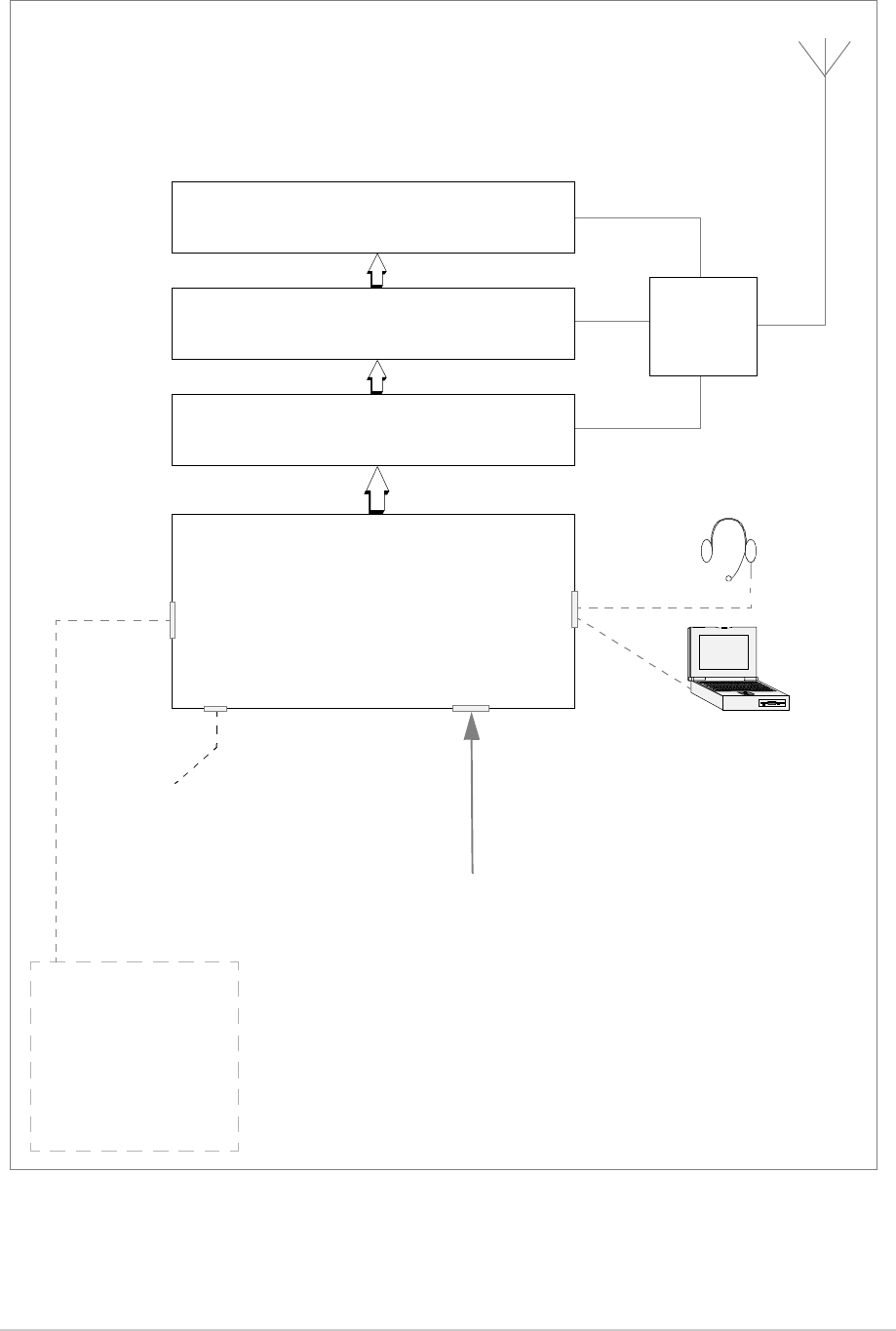
Fig 20 Remote operation. Operating the transmitter from a voice switch or remote controller.
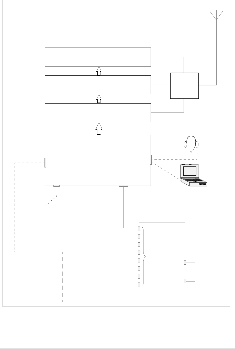
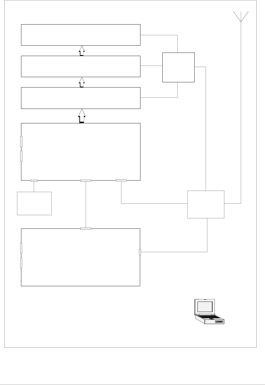
Fig 21 With the transmitter connected through an RSE2 equipment. RSE2 is the remote site
equipment in a Park Air Multi-Access Remote Control (MARC) system. This system
provides automatic and manual main/standby switching and routes BIT information to allow
radio, site and system status to be displayed at the control site.
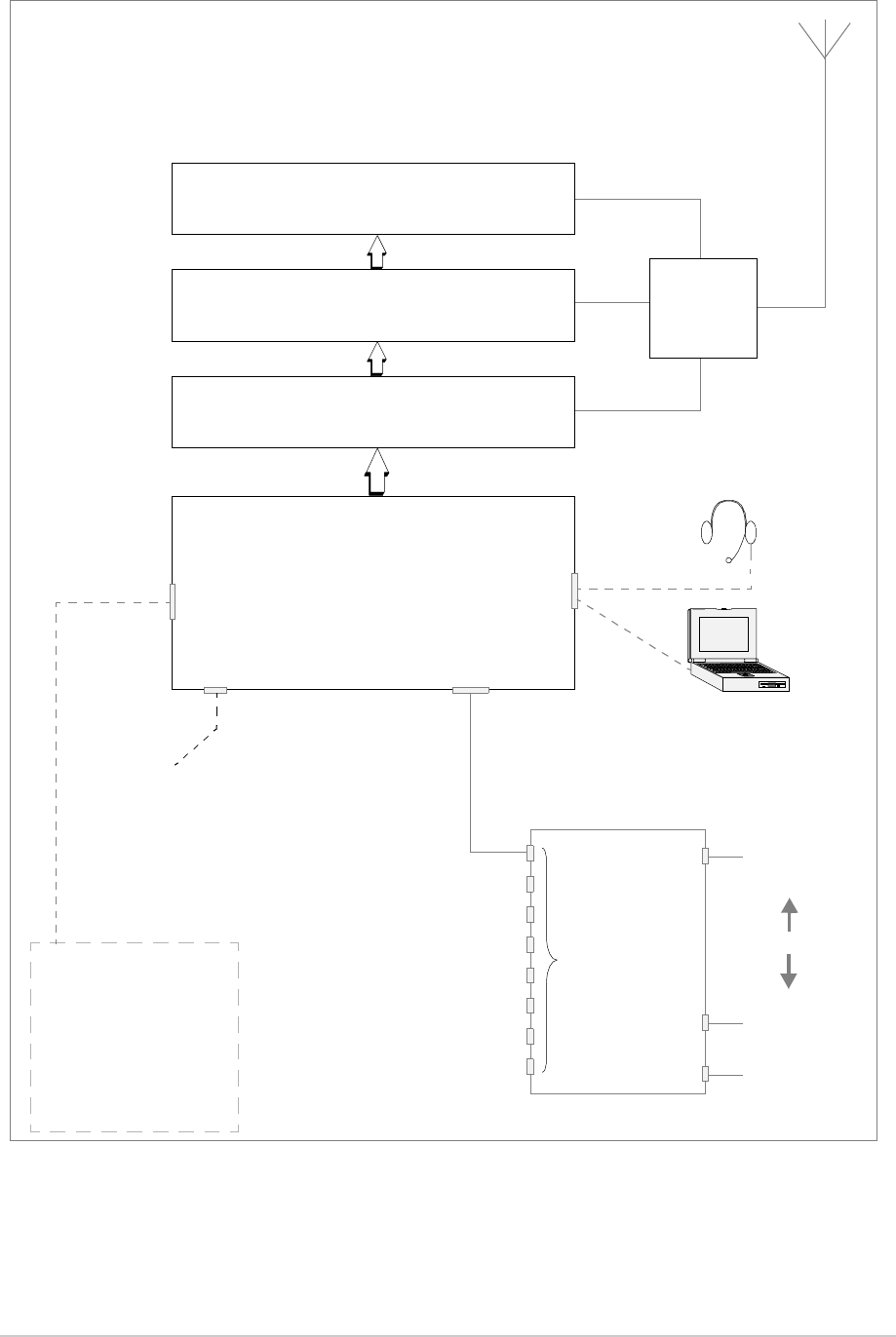
Fig 22 With the transmitter connected through an E1 Radio Interconnect (E1-RIC). By using
E1-RICs, a digital end-to-end system using E1 data streams can be configured.
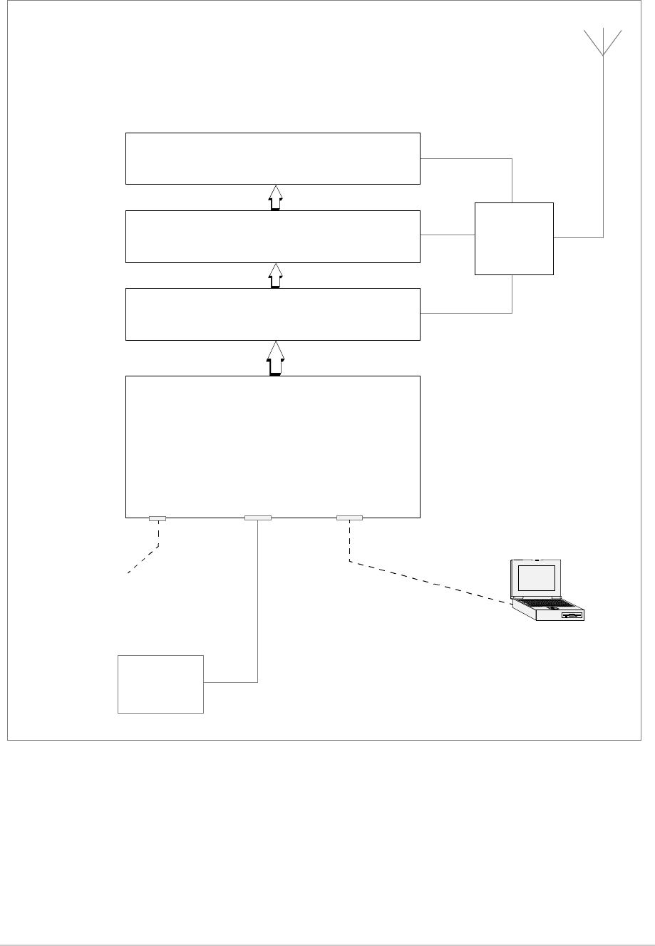
Fig 23 The transmitter is configured with a receiver to provide Mode 2 operation (note that mode
2 software must be loaded to allow this configuration).
Fig 24 The transmitter is configured for Mode 3 operation (note that mode 3 software must be
loaded to allow this configuration).
The following pages show the illustrations listed above and then detail the pin-outs for the drive assembly
connectors used to configure the transmitter for the required operational usage. The Microphone/
Diagnostics and the Reference connectors are fitted to the drive assembly’s front panel; other
connectors, as shown in Fig 25, are fitted to the rear panel.
T6T 300 Watt VHF Transmitter Page 80 Installation
Fig 19 Transmitter Configured for Local Operation
Amplifier 1
Amplifier 2
Amplifier 3
Combiner
Drive Assembly
Reference
Connector Microphone/Diagnostics
Connector
Microphone/Headset
for transmissions and
monitoring sidetone
Laptop (or PC)
required when using VFP
Frequency Counter
for Maintenance
Facilities
Connector
Antenna change-over output
Ready output
Tape output
BIT test input signal
Inhibit input signal
28 Vdc output
VSWR input signal
PTT relay output
E-BIT input
Optional facilities
(use as required)
T6T 300 Watt VHF Transmitter Page 81 Installation
Fig 20 Transmitter Configured for Remote Operation
Amplifier 1
Amplifier 2
Amplifier 3
Combiner
Drive Assembly
Reference
Connector
Microphone/Diagnostics
Connector
Microphone/Headset for
engineering purposes
Laptop (or PC)
required when using VFP
Frequency Counter
for Maintenance
Facilities
Connector
Antenna change-over output
Ready output
Tape output
BIT test input signal
Inhibit input signal
28 Vdc output
VSWR input signal
PTT relay output
E-BIT input
Optional facilities
(use as required)
MARC Connector or
MARC Audio Connector
Audio and PTT
Signals from Control Equipment
T6T 300 Watt VHF Transmitter Page 82 Installation
Fig 21 Transmitter Configured for use with a MARC RSE2
Amplifier 1
Amplifier 2
Amplifier 3
Combiner
Drive Assembly
Reference
Connector
Microphone/Diagnostics
Connector
Microphone/Headset for
engineering purposes
Laptop (or PC)
required when using VFP
Frequency Counter
for Maintenance
Facilities
Connector
Antenna change-over output
Ready output
Tape output
BIT test input signal
Inhibit input signal
28 Vdc output
VSWR input signal
PTT relay output
E-BIT input
Optional facilities
(use as required)
MARC Connector
RSE2
Equipment
Connectors
Audio
PTT
MARC Data
Audio and PTT
from
control equipment
MARC Data
to and from
control centre
T6T 300 Watt VHF Transmitter Page 83 Installation
Fig 22 Transmitter Configured for use with an E1-RIC
Note:
E1-RIC can be used in an E1 digital end-to-end system, or using 4-wire E and M lines.
Amplifier 1
Amplifier 2
Amplifier 3
Combiner
Drive Assembly
Reference
Connector
Microphone/Diagnostics
Connector
Microphone/Headset for
engineering purposes
Laptop (or PC)
required when using VFP
Frequency Counter
for Maintenance
Facilities
Connector
Antenna change-over output
Ready output
Tape output
BIT test input signal
Inhibit input signal
28 Vdc output
VSWR input signal
PTT relay output
E-BIT input
Optional facilities
(use as required)
T1/E1 Connector
E1-RIC
Radio
Connectors
E1 Data Stream
containing Audio,
Signalling and
Audio and PTT
from
control equipment
MARC Data
to and from
control centre
MARC Data
E1 Data Stream
containing Audio,
Signalling and
MARC Data
Or (see Note)
T6T 300 Watt VHF Transmitter Page 84 Installation
Fig 23 Transmitter Configured with Receiver for Mode 2 Operation
Amplifier 1
Amplifier 2
Amplifier 3
Combiner
Drive Assembly
HDLC
Connector
Microphone/Diagnostics
Connector
Laptop (or PC) required
when using VFP. Connects to
Frequency Counter
for Maintenance connects
T1/E1 Connector
T6R Receiver
T1/E1 Connector
Mode 2
Network
Computer
Antenna
Connector
Fast Antenna
Change-Over
Switch
Facilities
Connector
Reference
Connector
Microphone/Diagnostics
Connector
Reference
Connector
to Reference Connector Microphone/Diagnostics Connector
T6T 300 Watt VHF Transmitter Page 85 Installation
Fig 24 Transmitter Configured for Mode 3 Operation
Amplifier 1
Amplifier 2
Amplifier 3
Combiner
Drive Assembly
Reference
Connector Microphone/Diagnostics
Connector
Laptop (or PC)
required when using VFP
Frequency Counter
for Maintenance
T1/E1 Connector
Mode 3
Network
Computer
T6T 300 Watt VHF Transmitter Page 86 Installation
Front Panel Connectors
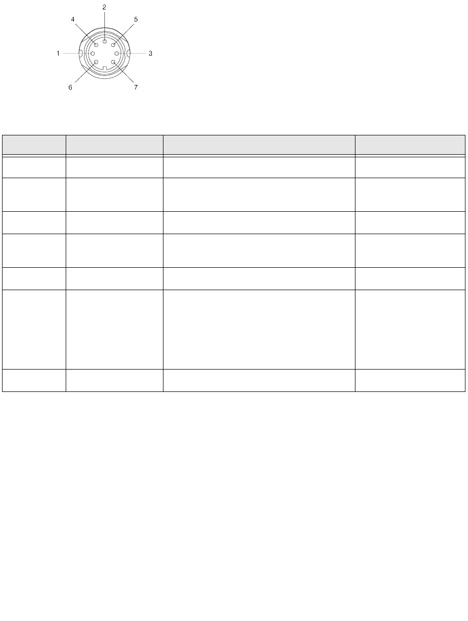
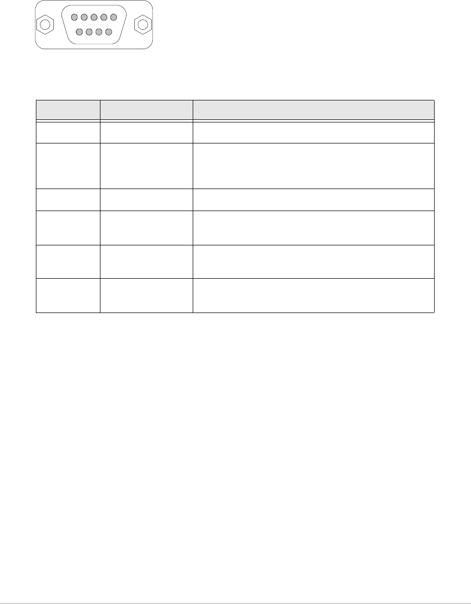
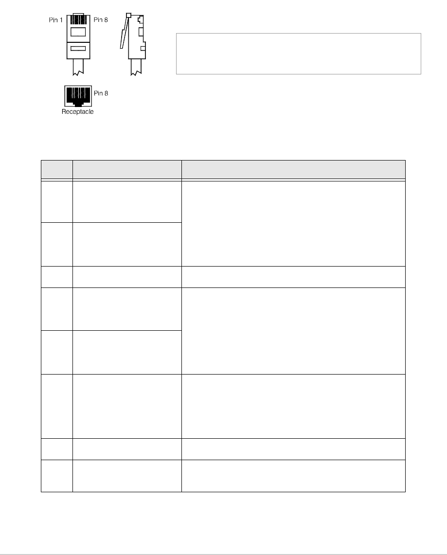
Microphone/Diagnostics Connector
The Microphone/Diagnostics connector is a self-locking 7-way DIN socket used for connecting a
microphone, microphone/headset or PC. The connector pin-out is detailed in Table 16.
Reference Connector
The Reference connector is an SMB plug used to monitor the radio’s reference frequency. It monitors
the frequency at a level of 100 mV (±50 mV) with less than -10 dBc harmonics.
Table 16 Microphone/Diagnostics Connector
Pin Number Signal Characteristic Usage
1 Microphone ground 0 V. Microphone/Headset
2 Transmit data RS232. 115200 baud, 8 data bits, 1 stop bit,
no parity, no handshaking.
PC
3 Microphone PTT 0 V to PTT. Microphone/Headset
4 Receive data RS232. 115200 baud, 8 data bits, 1 stop bit,
no parity, no handshaking.
PC
5 Sidetone – Microphone/Headset
6 Microphone input To ensure correct VOGAD operation, the
following microphone input levels are
required:
Passive setting: between 2 and 35 mV
Active setting: between 8 and 140 mV.
Microphone/Headset
7 Ground 0 V. PC
Pin-out of the Microphone/Diagnostics connector looking into
the mating face of the chassis mounted socket.
A suitable free plug is detailed in Table 14 on page 70.
T6T 300 Watt VHF Transmitter Page 87 Installation
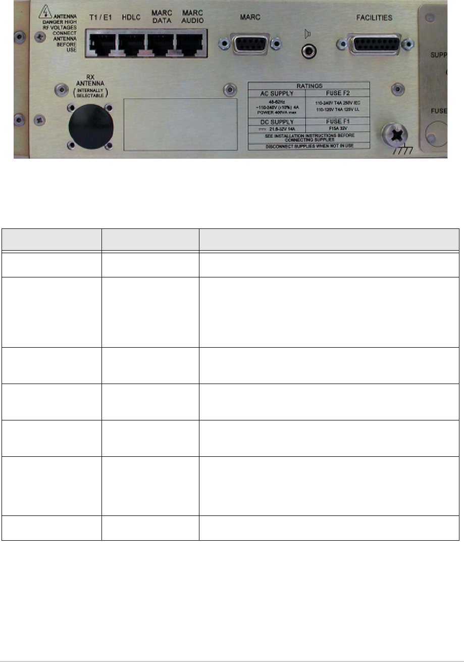
Rear Panel Connectors
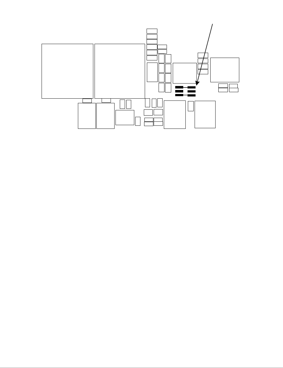
Fig 25 Drive Assembly External Signal Connectors
Table 17 Rear Panel Connector Usage
Connector Type Usage
External speaker 3.5 mm stereo jack Connects an external loudspeaker for monitoring sidetone.
MARC 9-way D-type Used to connect to a MARC remote site equipment RSE2
Used to connect a T6 controller or hub
Used to terminate external audio and PTT signals when a
remote site equipment or T6 controller is not used.
MARC audio RJ48 Used as an alternative to the MARC connector for terminating
external audio and PTT signals.
MARC data RJ48 Used as an alternative to the MARC connector for terminating
data signals to and from a compatible data system.
Facilities 15-way D-type Provides a number of optional facilities that can be used as
required. Table 24 on page 95 lists the facilities.
T1/E1 RJ48 Used for connecting the radio to a Mode 3 network computer,
connecting a transmitter and receiver together as a Mode 2
base station, or for connecting to a digital voice and data
network.
HDLC RJ48 Used to connect to a Mode 2 network computer.
T6T 300 Watt VHF Transmitter Page 88 Installation
MARC Connector
The MARC connector is a 9-way D-type socket used to connect the transmitter to a MARC remote site
equipment, or it can also be used for normal remote operation.
As an alternative to using this connector, the RJ48 style MARC Audio and MARC Data connectors can
be used to provide the same functions.
The MARC connector pin-out is shown below and detailed in Table 18.
Note:
The line level figures shown for the MARC connector are the limits when testing the transmitter
using a sine wave; the line level will be 10 dB above the line level setting. See the information
supplied under the heading ‘Line Level Setting’ in Operation.
Table 18 MARC Connector
Pin Number Signal Characteristic
1 Ground 0 V.
2
3Audio line in (+)
Audio line in (-) Balanced 600 ohm, -30 to +10 dBm.
Phantom keying can be superimposed on the audio
lines. See Fig 27.
4 PTT input Remote PTT signal input. See Fig 26.
5 Output supply This output is between 21.6 and 32 Vdc (nominally
28 V) fused at 500 mA.
6
7
Data in (+)
Data in (-)
RS422 differential asynchronous data at 9600 baud,
8 data bits, 1 stop bit, no parity, no handshaking.
8
9Data out (+)
Data out (-) RS422 differential asynchronous data at 9600 baud,
8 data bits, 1 stop bit, no parity, no handshaking.
Pin-out of MARC connector looking into the mating face of the
chassis mounted socket.
A suitable free plug is detailed in Table 14 on page 70.
15
69
T6T 300 Watt VHF Transmitter Page 89 Installation
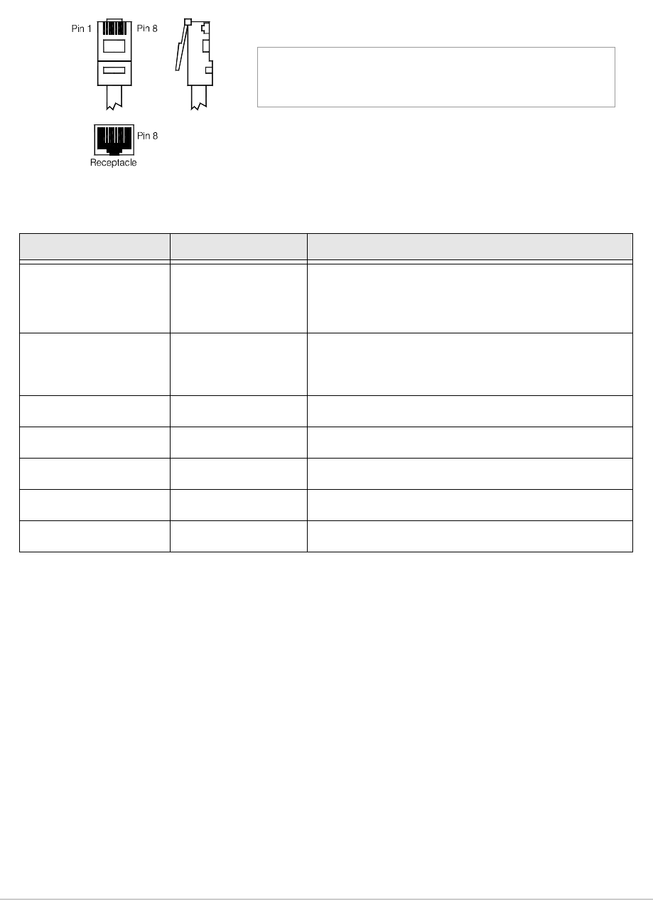
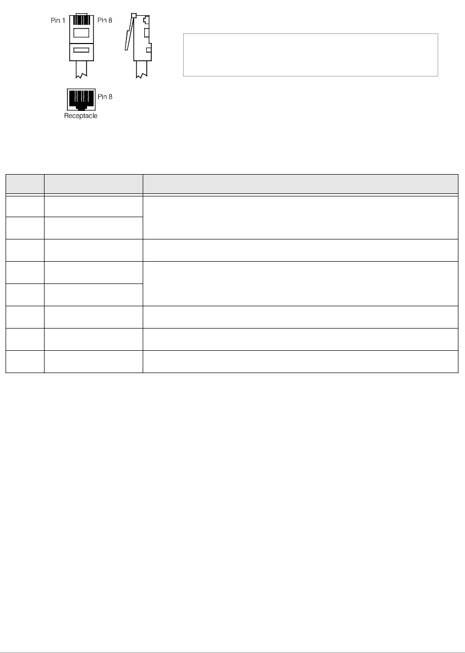
MARC Audio Connector
The MARC Audio connector is an 8-way RJ48 socket. It can be used as an alternative to the MARC
connector for audio and PTT connections. The connector pin-out is shown below and detailed in
Table 19.
Note:
The line level figures shown for the MARC Audio connector are the limits when testing the
transmitter using a sine wave; the line level will be 10 dB above the line level setting. See the
information supplied under the heading ‘Line Level Setting’ in Operation.
Table 19 MARC Audio Connector
Pin Number Signal Characteristic
1
2
Audio line in (-)
Audio line in (+)
Balanced 600 ohm, -30 to +10 dBm.
Phantom keying can be superimposed on the audio
lines. See Fig 27.
3 Fast antenna
change-over/PTT
(output)
Open collector NPN transistor grounding output,
200 mA maximum, configurable normally open or
normally closed.
4 Not used -
5 Not used -
6 PTT (input) Remote PTT signal input. See Fig 26.
7 Ground 0 V.
8 Not used -
Pin 1
RJ48 Plug
Numbering is shown looking from the top of the connector.
The top is being viewed when the lever is on the bottom.
T6T 300 Watt VHF Transmitter Page 90 Installation
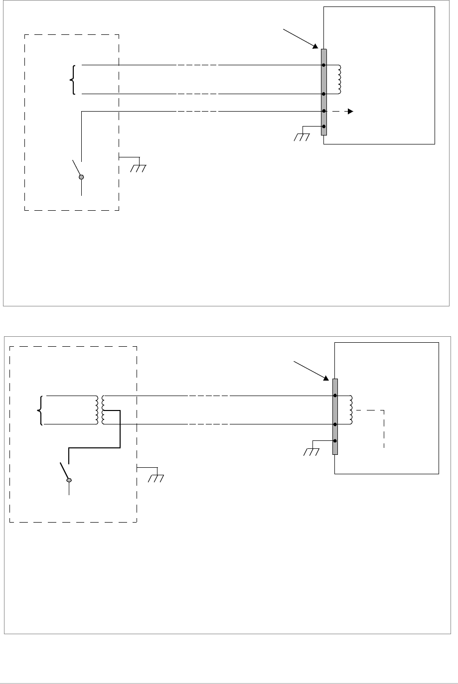
Fig 26 Remote Keying
Fig 27 Phantom Keying
T6T Transmitter
MARC Audio Connector
Audio is pins 1 and 2.
Audio line 1
Audio line 2
PTT Reference Voltage
(0 V, +14 V or -14 V)
Set from front panel
PTT
Switch
VPTT
The transmitter reference voltage (0 V, +14 V or -14 V) is selected from the Polarities screen:
❑PTT is active when VPTT differs from the transmitter reference voltage by more than 10 V.
❑PTT is inactive when VPTT differs from the transmitter reference voltage by less than 1 V.
❑Maximum value of VPTT is ±60 V with respect to transmitter reference voltage.
Example:
To use 0 V as the keying potential, VPTT = 0 V; set transmitter reference voltage to +14 V; set PTT In to STD.
Cross-Site Lines
Audio
Circuit
PTT input requires at least 1 mA to operate.
Input will draw no more than 6 mA.
PTT is pin 6
MARC Connector
Audio is pins 2 and 3.
PTT is pin 4
MARC or
MARC Audio
Connector
Control
Equipment Ground is pin 7.
Ground is pin 1.
T6T Transmitter
PTT
Switch
Reference Voltage
(0 V, +14 V or -14 V)
Set from front panel
V
PTT
To reduce the number of cross-site lines between the control site and the transmitter, phantom keying may be employed.
This method has the keying potential (VPTT) superimposed on the audio lines instead of using a separate line.
The transmitter reference voltage (0 V, +14 V or -14 V) is selected from the Polarities screen:
❑PTT is active when VPTT differs from the transmitter reference voltage by more than 10 V.
❑PTT is inactive when VPTT differs from the transmitter reference voltage by less than 1 V.
❑Maximum value of VPTT is ±60 V with respect to transmitter reference voltage.
Example:
To use 0 V as the keying potential, VPTT = 0 V; set transmitter reference voltage to +14 V; set PTT In to STD.
Audio lines with phantom keying
signal superimposed
PTT input requires at least 1 mA to operate.
Input will draw no more than 6 mA.
MARC Audio Connector
Audio is pins 1 and 2.
MARC Connector
Audio is pins 2 and 3.
MARC or
MARC Audio
Connector
Audio
Circuit
Control
Equipment
T6T 300 Watt VHF Transmitter Page 91 Installation
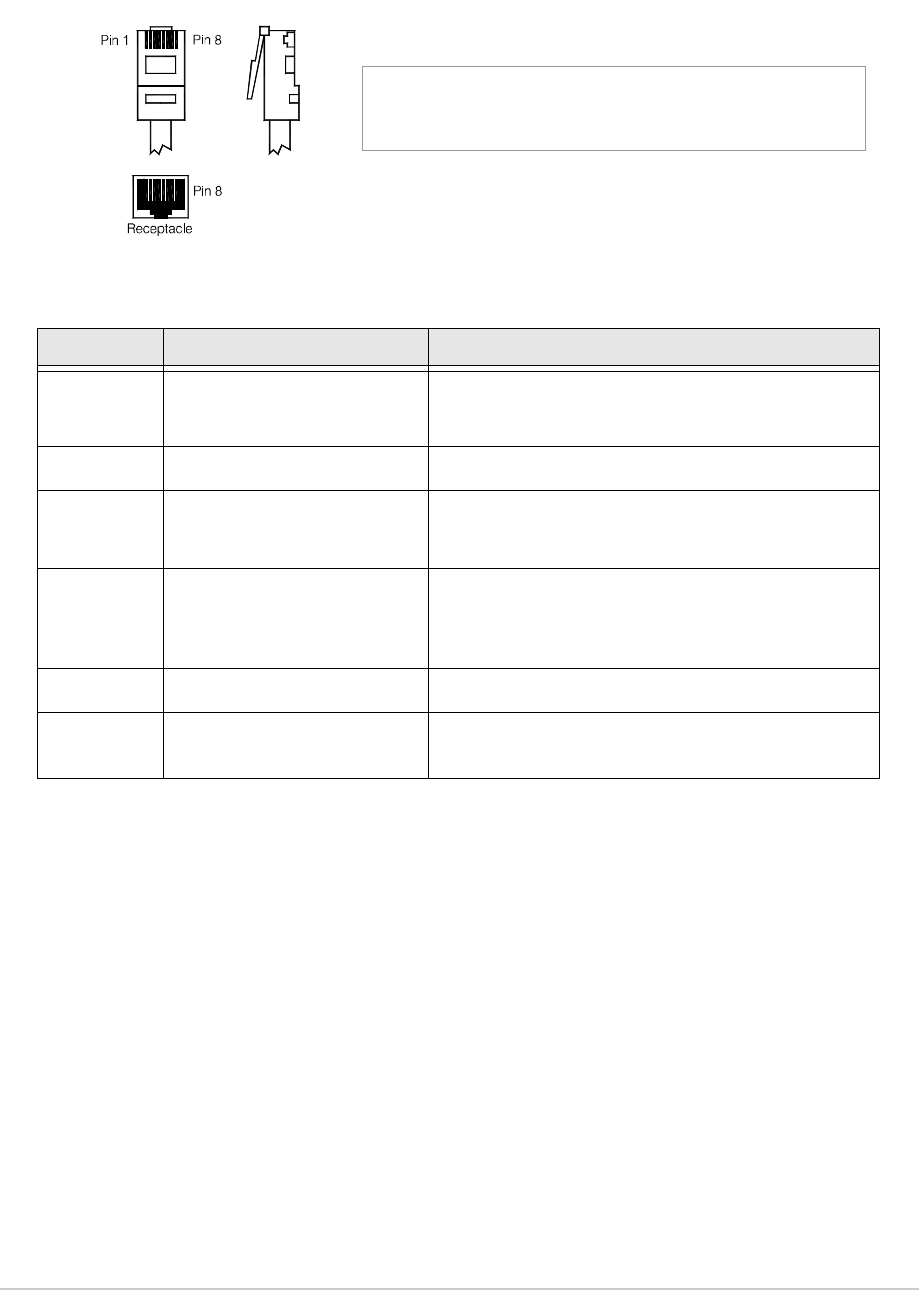
MARC Data Connector
The MARC Data connector is an 8-way RJ48 socket. It can be used as an alternative to the MARC
connector for data connections. The connector pin-out is shown below and detailed in Table 20.
Table 20 MARC Data Connector
Pin Number Signal Characteristic
1
2
Data in (-)
Data in (+)
RS422 differential asynchronous data, 9600 baud,
8 data bits, 1 stop bit, no parity, no handshaking.
3 Not connected -
4
5
Data out (+)
Data out (-)
RS422 differential asynchronous data, 9600 baud,
8 data bits, 1 stop bit, no parity, no handshaking.
6 Remote supply on/off 0 V to switch off.
Note: Rear panel switch must be in the On position for
this function to operate.
7 Ground 0 V.
8 Output supply This output is between 21.6 and 32 Vdc (nominally
28 V) fused at 500 mA.
Pin 1
RJ48 Plug
Numbering is shown looking from the top of the connector.
The top is being viewed when the lever is on the bottom.
T6T 300 Watt VHF Transmitter Page 92 Installation
T1/E1 Connector
The T1/E1 8-way RJ48 socket is used to:
❑Connect voice, signalling and RCMS data to a digital network
❑Connect a Mode 3 network computer
❑Connect a transmitter and receiver together when the receiver is configured as part of a Mode 2
base station.
The connector pin-out is shown belown and detailed in Table 21.
Table 21 T1/E1 Connector
Pin Signal Characteristic
1 RRing T1 - Balanced 100 ohm (±10%), 1.544 Mbits per
second (±50 ppm), AMI/B8ZS Coding.
E1 - Balanced 120 ohm (±10%), 2.048 Mbits per
second (±50 ppm), AMI/HDB3 Coding.
Protected with 28 V differential and common mode
clamp and 1.25 A fuse in each line.
2RTip
3 Not connected -
4 TRing T1 - Balanced 100 ohm (±10%), 1.544 Mbits per
second (±50 ppm), AMI/B8ZS Coding.
E1 - Balanced 120 ohm (±10%), 2.048 Mbits per
second (±50 ppm), AMI/HDB3 Coding.
Protected with 28 V differential and common mode
clamp and 1.25 A fuse in each line.
5TTip
6 Remote on/off An input that is primarily used by a Park Air E1-RIC
equipment to switch the radio on and off (0 V = off,
5 V = on). For this facility to work, the radio’s rear
panel Supply switch must be set to on and the E1-RIC
must be powered from an external source.
7 Ground 0 V.
8 20 to 35 Vdc (nominally
28 V)
Output supply used to power an E1-RIC.
Pin 1
RJ48 Plug
Numbering is shown looking from the top of the connector.
The top is being viewed when the lever is on the bottom.
T6T 300 Watt VHF Transmitter Page 93 Installation
HDLC Connector
The HDLC connector is an 8-way RJ48 socket used for connecting to a Mode 2 network computer. The
connector pin-out is shown below and detailed in Table 22.
.
Table 22 HDLC Connector
Pin Signal Characteristic
1 HDLC RX A (input)
RS422 differential synchronous data, 128 kbytes per second (±50 ppm).
2 HDLC RX B (input)
3 HDLC CL A (output) RS422 differential synchronous data, 128 kbytes per second (±50 ppm).
4 HDLC TX B (output)
RS422 differential synchronous data, 128 kbytes per second (±50 ppm).
5 HDLC TX A (output)
6 HDLC CL B (output) Pair to pin 3.
7 Ground 0 V.
8 Output supply This output is between 21.6 and 32 Vdc (nominally 28 V) fused at 500 mA.
Pin 1
RJ48 Plug
Numbering is shown looking from the top of the connector.
The top is being viewed when the lever is on the bottom.

T6T 300 Watt VHF Transmitter Page 94 Installation
External Speaker
The External Speaker connector is a 3.5 mm stereo jack used for connecting an external speaker to the
transmitter to provide sidetone. This speaker should be a high impedance active type.
Table 23 External Speaker
Pin Signal Characteristic
Tip Speaker drive (output) 0 to 3 V pk-pk. Connected directly to Ring.
Ring Speaker drive (output) 0 to 3 V pk-pk. Connected directly to Tip.
Sleeve Ground 0 V.

T6T 300 Watt VHF Transmitter Page 95 Installation
Facilities Connector
The Facilities connector is a 15-way D-type filtered socket used for connecting to associated parts of a
system. The connector pin-out is shown below and detailed in Table 24.
Table 24 Facilities Connector
Pin Number Signal Characteristic
1 Ground 0 V.
2 E-BIT (input) An external BIT input that connects from any ancillary equipment having
a compatible BIT alarm output.
When this input is active, the transmitter’s front panel Alarm indicator
flashes and an E-BIT message is displayed on the LCD. The input is
TTL having a 4.7 kohm pull-up resistor to 5 V. The input is configurable
from the front panel to be active high or low.
3 PTT output Grounding solid state relay. +60 to -60 V, ac or dc, 100 mA maximum,
configurable normally open or normally closed. Activated 35 ms (±1 ms)
before the start of the power ramp up to allow for the antenna relay pull-
in time.
4 External VSWR input Used to indicate an external VSWR fault. TTL input with 4.7 kohm pull-
up to 5 V. Configurable active high or low.
5
6
Antenna change-over
(output)
Antenna change-over
common (output)
Solid state relay linked to pin 6. See Fig 28 for further detail.
Solid state relay linked to pin 5.
7 Not used -
8 Ground 0 V.
9 Output supply This output is between 21.6 and 32 Vdc (nominally 28 V) fused at
500 mA.
10 Inhibit (input) Active signal prevents the transmitter keying. TTL with 4.7 kohm pull-up
to 5 V. Configurable active high or low.
11 BIT interruptive test
(input) Active signal initiates a BIT test. TTL with 4.7 kohm pull-up to 5 V.
Configurable active high or low. Must be asserted for >300 ms.
12 Not used -
13 Ready (output) An output that is active when the radio is ready to transmit and no faults
are detected. Open collector NPN transistor grounding output, 200 mA
maximum, configurable normally open or normally closed.
14 Tape (output) An audio output for connection to a recording system. 0 dBm fixed
output into 600 ohm for 90% modulation depth.
15 Reserved (output) Do not connect to pin 15 unless advised to do so by Park Air.
18
915
Pin-out of Facilities connector looking into the mating face of
the chassis mounted socket.
A suitable free plug is detailed in Table 14 on page 70.
T6T 300 Watt VHF Transmitter Page 96 Installation
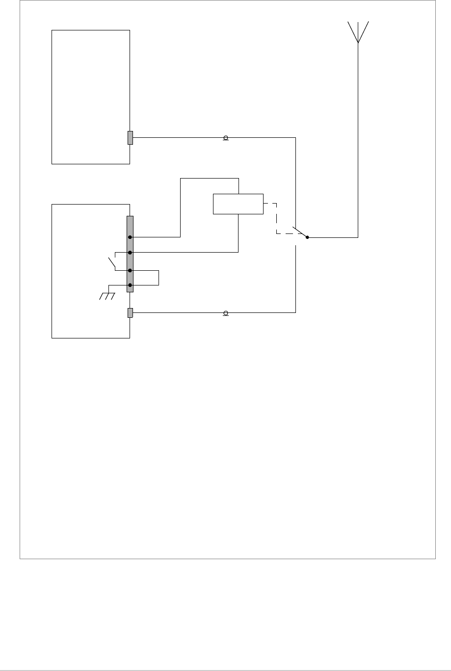
Fig 28 Example: Using the Antenna Change-over Output
T6T Transmitter
6
5
Facilities
Connector
Antenna
T6T Transmitter
Facilities
Connector
Antenna
9
28 Vdc (nominal)
Control
(Main)
(Standby)
Antenna
Main/Standby
Transmit Relay
Example
This example shows the Antenna Change-over Output configured to control the antenna switching between main
and standby transmitters. The potential on Facilities connector pin 6 is switched through to pin 5 when the standby
transmitter is keyed; in this example, pin 6 is linked to ground. This energizes the Main/Standby Transmit Relay to
route the standby transmitter to the antenna.
Other Configurations
The antenna change-over output can be configured in other ways to suit the user’s requirement subject to:
❑Pin 6 can be any potential between -60 and +60 V, ac or dc
❑The maximum current drawn must not exceed 100 mA
❑The output at pin 5 is configurable normally open or normally closed from the Polarities screen
❑The internal solid state switch activates 35 ms before the start of the power ramp to allow for the antenna
relay pull-in time.
8
Solid State
Relay
Link
Maintenance
T6T 300 Watt VHF Transmitter Page 98 Maintenance
Introduction
This topic gives the scheduled and unscheduled maintenance procedures for the T6T 300 watt VHF
transmitter and shows how to use the Virtual Front Panel (VFP).
Configuration
T6 radios are configured in respect of hardware and software.
Hardware Configuration
The transmitter consists of a drive assembly, three amplifiers and a combiner. Each has an identification
label showing the model, part number, serial number and the modification state. The modification state
identifies the hardware configuration.
Scheduled Maintenance A scheduled maintenance procedure is given on page 100.
Park Air recommends that this task be completed every twelve
months.
Unscheduled Maintenance Normally, the T6T transmitter is considered a Line Replaceable
Unit (LRU) and should be replaced with a serviceable spare if a
fault occurs. The faulty transmitter should then be returned to Park
Air for repair.
In certain circumstances, Park Air Customer Support may suggest
that the user change one of the transmitter modules. Dismantling
and assembly instructions are therefore given under the heading
Unscheduled Maintenance starting on page 104.
Using the VFP Operating parameters can be set from the drive assembly’s front
panel, or by using the VFP. Some additional functions are available
from the VFP. See page 126.
Model:
Part No:
S / No:
Mod Record:
T6T VHF Drive Assembly
24-06633001/3
2L0001
X 6 7 8 9 10 11 12 13
Park Air Systems Ltd England
PAE Model:
Part No:
S / No:
Mod Record:
T6T VHF Amplifier
24-31633001/2
2L0001
X 6 7 8 9 10 11 12 13
Park Air Systems Ltd England
PAE Model:
Part No:
S / No:
Mod Record:
T6T VHF Combiner
24-33633001/2
2L0001
1 2 3 4 5 6 7 8 9 10
Park Air Systems Ltd England
PAE
Drive Assembly Label Amplifier Label Combiner Label

T6T 300 Watt VHF Transmitter Page 99 Maintenance
Software Configuration
A white label fitted to the top
cover lists the radio’s software
configuration.
In this example there are three
fills: AM-Voice, Mode 2 and
Mode 3.
Software Configuration Label
Replacement Modules
To ensure compatibility when replacing a radio or a module, the configuration should be the same (see
the previous headings: Hardware Configuration and Software Configuration).
Spare modules received from Park Air are supplied with a Spares Instruction that details the
configuration of the module and any special instructions. If in any doubt regarding the suitability of spare
modules contact Park Air Customer Support.
Software Configuration
Part Order No. B63300HS
Software Mode Part No.
Fill 1 AM_VOICE 65-00000465
Fill 2 2 65-00000466
Fill 3 3 65-00000467
Fill 4
2K1234

T6T 300 Watt VHF Transmitter Page 100 Maintenance
Scheduled Maintenance
Park Air recommends that scheduled maintenance is carried out at twelve-monthly intervals. Scheduled
maintenance comprises the following checks:
Cleaning and Checking Security of Connectors
Remove all dust and dirt from the equipment exterior using a lint-free cloth and camel hair brush. Check
all external connections are secure and free from damage.
Setting the Transmitter Internal Reference Frequency
To set the transmitter internal reference frequency, use the following procedure. Note that references to
the switch in the procedure mean the Scroll/Select switch.
(6) Turn the switch clockwise until Exit is highlighted, then press the switch. You are returned to the
Main screen.
(7) Disconnect the frequency counter.
(8) If 5-offset carrier operation is required, complete the procedure Setting a 5-Offset Carrier
Frequency on page 101.
Number Check Tools/Test Equipment Required
1 Ensure the equipment is clean and that external
connectors are securely fitted.
Camel hair brush/clean lint-free
cloths.
2 Check and reset (if required) the transmitter’s
internal frequency reference.
VHF frequency counter.
3 Perform a BIT interruptive test.
4 Perform an ac and dc change-over check (if both
supplies are connected).
Control Screen
Settings Screen
Fr equency
Channel
S e t t i n g s
E x i t
B a n d E d g e s
R e f F r e q 5 0 . 0 %
B a c k l i g h t 0 3 0 s
E x i t < < > >
(1) If the transmitter operates with 5-offset
carrier (that is, set with a 4 kHz or 8 kHz
offset) reset the offset to zero.
(2) Connect a frequency counter to the front
panel Reference connector.
(3) From the Main screen, press the switch to
display the Control screen. Turn the
switch until Settings is highlighted. Press
the switch.
(4) Ensure the Settings screen is displayed.
Turn the switch until Ref Freq is
highlighted, then press the switch.
(5) With Ref Freq selected turn the switch
clockwise or anti-clockwise until the
frequency counter reads 20.950000 MHz
±10 Hz, then press the switch.

T6T 300 Watt VHF Transmitter Page 101 Maintenance
Setting a 5-Offset Carrier Frequency
If a 5-offset carrier frequency is required, set the offset using the following procedure:
(1) Connect a 50 ohm frequency counter, through a 60 dB attenuator, to the combiner’s Antenna
connector.
(2) Set the required 25 kHz channel frequency; for example, 124.500 MHz.
(3) From the AM-Voice Mode Settings Screen set the required offset (+4 kHz, -4 kHz, +8 kHz or
-8 kHz); for example, a +4 kHz offset to give an operating frequency of 124.504 MHz.
(4) From the Settings screen select Ref Freq and press the Scroll/Select switch.
(5) Key the transmitter and adjust the reference frequency using the Scroll/Select switch until the
frequency counter displays the required operating frequency; for example, 124.504 MHz.
(6) When the frequency counter displays the exact operating frequency, press the Scroll/Select
switch and stop keying the transmitter.
Disconnect the test equipment and reconnect the antenna.

T6T 300 Watt VHF Transmitter Page 102 Maintenance
To Initiate a BIT Test
An interruptive BIT test cannot be initiated in Mode 2 or Mode 3.
(1) From the Main screen, press the switch to
display the Control screen. Turn the switch
until BIT is highlighted. Press the switch.
(2) Ensure the BIT menu is displayed. Turn
the switch until BIT Initiate is highlighted.
Press the switch.
(3) During the test, which takes approximately
two seconds, the Testing screen is
displayed.
(4) After the test, either a Pass or Fail screen
is displayed. Selecting OK takes the user
back to the BIT screen.
(5) If fail is displayed, scroll through the screen
to check the cause of the failure.
During an interruptive BIT test, the transmitter radiates modulated carrier waves at the set power.
Users should therefore obtain the necessary authority before initiating a test.
If the test is to be carried out with the antenna disconnected, ensure a load is fitted to the
transmitter’s Antenna connector.
In order to test the line input stages, an internally generated 1 kHz tone is injected into the line input
circuit. Any other audio present on the line input will cause the test to be inaccurate. Therefore the
transmitter MUST NOT be keyed during the test.
B I T
S / W C o n f i g
St andby
E x i t < <
B I T I n i t i a t e
E T I 0 0 0 0 0 : 0 0 h r s
A C S u p p l y O N
E x i t > >
T e s t i n g
P l e a s e W a i t
T e s t S t a t u s
P A S S
O K
T e s t S t a t u s
F A I L
O K

T6T 300 Watt VHF Transmitter Page 103 Maintenance
AC and DC Change-over Check
If both ac and dc input supplies are connected to the transmitter, carry out the following check:
(1) Confirm that both ac and dc supplies are connected to the transmitter. Ensure that the rear panel
Supply switches are set to the I (on) position.
(2) Confirm that the front panel Ready indicators are lit, the LCD is illuminated, and the transmitter
is operational.
(3) Switch off the ac supply from its source.
(4) Check that the transmitter continues to operate correctly from the dc supply. If accessed, the
front panel BIT screen will show AC Supply as off, and DC Supply as on. The value of the dc
supply is also shown.
T6T 300 Watt VHF Transmitter Page 104 Maintenance
Unscheduled Maintenance
The instructions given in this topic involve connecting dangerous voltage to the transmitter.
Maintenance should be carried out only by suitably qualified personnel.
When an ac supply is connected, dangerous voltage is present within the transmitter. Care
must be taken by personnel to avoid accidental contact with exposed circuitry during
maintenance or alignment procedures.
When the Supply switch is set to the Standby position, dangerous voltage is still present in
the transmitter's internal power supply circuitry. To ensure safe working, both ac and both
dc input supplies must be disconnected from the transmitter.
The output transistors used in the power amplifier (PA) contain the toxic material beryllium.
Although no procedures in this documentation instruct component removal, users should be
aware that there could be a hazard should the output transistors become damaged.
The T6T transmitter circuitry contains Electrostatic Sensitive Devices (ESDs). Personnel
must be aware of the precautions necessary to prevent damage to such devices.
Changes or modifications made to this equipment that are not expressly approved by
Park Air, or parties authorized by Park Air, could void the user’s authority to operate the
equipment.
When carrying out repairs to the PA module, care must be taken not to damage the gasket.
If the strips become damaged, they must be replaced. Failure to comply with this instruction
may compromise the transmitter’s Electromagnetic Compatibility (EMC) and breach
European Commission regulations.
When screws are inserted into the PA casting care must be taken not to exceed a torque of
6 Ibs/inch when tightening. This applies when replacing the top and bottom covers and
during the refitting of the PA modules.
WARNING Dangerous Voltage
WARNING Beryllium Hazard
Caution ESDs
Caution Unauthorized Modifications
Caution Repairs
T6T 300 Watt VHF Transmitter Page 105 Maintenance
Introduction
This topic provides the user with detailed instructions on the removal and replacement of modules within
the drive assembly and amplifiers. A faulty combiner must be replaced. When removing or refitting
modules, observe antistatic handling precautions. Do not change any potentiometer (or link) settings
unless detailed in these instructions. Potentiometers have been set using specialist equipment.
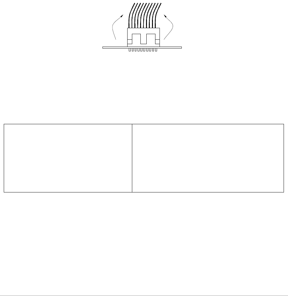
Molex KK Connectors
To remove Molex KK type connectors:
❑Free the locking mechanism on the connector by moving one side of the connector up, then move
the other side up (see Fig 29). The upward motion should only be as far as needed to free the
locking mechanism
❑DO NOT pull the cable to free the connector
❑Note that KK type connectors are designed to be removed in this manner to free the locking
mechanism. Do not use this procedure with non-KK type connectors as damage to the connector
may occur.
Fig 29 Molex KK Type Connector
Tools, Materials and Test Equipment Required
The following tools, materials and test equipment should be made available to complete the maintenance
tasks described in this topic.
❑Personal Computer (PC)
❑General Purpose Tool Kit (including
a 1.5 mm Allen key)
❑5 mm Nut Spinner
❑Camel Hair Brush
❑Clean Lint-free Cloths
❑Frequency Counter
❑Power Meter
❑Dummy Load
❑PC to Radio Interconnection Lead
(Park Air part number 17E12600001)
❑SMB to BNC Lead for Reference Frequency
(Park Air part number 17K11000004)
Lift 2Lift 1
PCB

T6T 300 Watt VHF Transmitter Page 106 Maintenance
T6T VHF Amplifier Procedures
Top and Bottom Covers
One of the top cover screws is covered with a warranty label that should not be tampered with unless
Park Air Customer Support has advised otherwise. When authorisation has been made the following
procedures should be followed.
To remove the top cover, locate and unscrew the 19 countersunk screws securing the top cover to the
mainframe. Access can then be gained to the Interface module and PSU Regulation module.
To remove the bottom cover, locate and unscrew the 15 countersunk screws securing the bottom cover
to the mainframe. Access can then be gained to the Combiner BIT module.
Removal and refitting of the following modules requires both top and bottom covers to be removed:
❑Power Supply modules
❑Combiner BIT module
❑PA modules
❑Front Panel assembly PCB.
Removing and Refitting the Interface Module
The Interface module is located as shown in Fig 34. A module removal diagram is shown in Fig 37.
Dangerous voltage is present within the T6T VHF amplifier. Care must be taken by personnel
to avoid accidental contact with exposed circuitry when the covers are removed and power
is applied to the radio.
Removal
Ensure that the amplifier is isolated from the ac and dc input supplies. Disconnect the drive assembly
cables at CN5 and CN8. Disconnect the antenna cable to the Combiner. Then proceed as follows:
(1) Unscrew the 19 countersunk screws and remove the amplifier top cover.
(2) Locate the Interface module and disconnect the following connectors:
❑CN2 10-way connector (10-way loom from Combiner BIT module CN15)
❑CN3 SMB connector (coaxial cable from Combiner BIT module CN27)
❑CN4 SMB connector (coaxial cable from Combiner BIT module CN16)
❑CN6 15-way connector (15-way ribbon cable from PSU Regulation module CN1)
❑CN7 10-way connector (10-way ribbon cable from Front Panel PCB).
(3) Gain access to the rear of the amplifier. Using a 5 mm nut spinner tool, remove the four screwloc
8 mm-4-40 UNC stud spacers and wavy washers that secure the Interface module connectors
CN5 and CN8 to the rear panel.
(4) Also at the rear of the amplifier, remove the two M3 x 8 mm screws that secure the blanking plate
and the Interface module.
(5) Remove the five M3 x 8 mm screws that secure the module to the amplifier mainframe.
(6) Remove the module from the chassis.
WARNING Dangerous Voltage

T6T 300 Watt VHF Transmitter Page 107 Maintenance
Refitting
To refit the Interface module, proceed as follows:
(1) Place the module in position. Ensure no wires are trapped by the module.
(2) Ensure the module interface connectors CN5 and CN8 are located correctly and are aligned with
the screw holes in the rear panel. Fit the four screwloc 8 mm-4-40 UNC screws and wavy
washers, previously removed, but leave them loose.
(3) Fit the two M3 x 8 mm screws, previously removed, that secure the blanking plate and Interface
module, but leave them loose.
(4) Fit the five M3 x 8 mm screws, previously removed, that secure the module to the transmitter
mainframe, but leave them loose.
(5) Using a 5 mm nut spinner tool, tighten the four screwloc 8 mm-4-40 UNC screws and wavy
washers that secure the connectors; then tighten all seven M3 x 8 mm screws that secure the
module to the amplifier mainframe.
(6) Refit the following connectors to the module:
❑CN2 10-way connector (10-way loom from Combiner BIT module CN15)
❑CN3 SMB connector (coaxial cable from Combiner BIT module CN27)
❑CN4 SMB connector (coaxial cable from Combiner BIT module CN16)
❑CN6 15-way connector (15-way ribbon cable from PSU Regulation module CN1)
❑CN7 10-way connector (10-way ribbon cable from Front Panel PCB).
(7) Connect the drive assembly cables at CN5 and CN8. Connect the antenna cable to the
Combiner.
(8) Re-establish the ac and/or dc supplies.
(9) Switch power on at the radio using the rear mounted Supply switch.
(10) Ensure the front panel Ready indicator is lit and the Alarm indicator is unlit.
(11) Carry out the Calibrate routine using the Virtual Front Panel (VFP), as detailed in the procedure
To Calibrate the Transmitter on page 130.
(12) Carry out a BIT interruptive test as detailed in the procedure To Initiate a BIT Test on page 102.
(13) Set the rear panel Supply switch to Standby and remove the VFP connector. Isolate the amplifier
from the ac and/or dc supplies.
(14) Refit the amplifier top cover. The transmitter can now be returned to service.

T6T 300 Watt VHF Transmitter Page 108 Maintenance
Removing and Refitting the PSU Regulation Module
The PSU Regulation module is located as shown in Fig 34. A module removal diagram is shown in
Fig 38.
Dangerous voltage is present within the T6T VHF amplifier. Care must be taken by personnel
to avoid accidental contact with exposed circuitry when the covers are removed and power
is applied to the radio.
Removal
Before attempting to remove the PSU Regulation module, ensure that the amplifier is isolated from the
ac and dc input supplies. Disconnect the drive assembly cables at CN5 and CN8. Disconnect the
antenna cable to the Combiner. Then proceed as follows:
(1) Unscrew the 19 countersunk screws and remove the transmitter top cover.
(2) Locate the PSU Regulation module and remove the three M3 x 8 mm captive washer screws that
secure the module to the amplifier mainframe.
(3) Carefully raise the module to gain access to the module connectors.
(4) Disconnect the following connectors:
❑CN6 6-way connector (6-way to 10-way loom to Combiner BIT module CN12)
❑CN4 14-way connector (14-way ribbon cable to Interface module CN6)
❑CN3 3-way connector (part of loom to Combiner BIT module CN7)
❑CN7 3-way connector (3-wire loom to rear panel On/Off switch)
❑CN2 2-way connector (part of loom to Combiner BIT module CN7)
❑CN1 4-way connector (part of loom to Combiner BIT module CN7).
(5) Remove the module from the chassis.
Refitting
To refit the PSU Regulation module, proceed as follows:
(1) While holding the module in position, connect the following connectors:
❑CN1 4-way connector (part of loom to Combiner BIT module CN7)
❑CN2 2-way connector (part of loom to Combiner BIT module CN7)
❑CN7 3-way connector (3-wire loom to rear panel On/Off switch)
❑CN3 3-way connector (part of loom to Combiner BIT module CN7)
❑CN4 14-way connector (14-way ribbon cable to Interface module CN6)
❑CN6 6-way connector (6-way to 10-way loom to Combiner BIT module CN12).
(2) Locate the module in position. Ensure no wires are trapped by the module.
(3) Secure the module to the amplifier mainframe using the three M3 x 8 mm captive washer screws
removed during disassembly.
(4) Connect the drive assembly cables at CN5 and CN8. Connect the antenna cable to the
Combiner.
WARNING Dangerous Voltage

T6T 300 Watt VHF Transmitter Page 109 Maintenance
(5) Re-establish the ac and/or dc supplies.
(6) Switch power on at the radio using the rear mounted Supply switch.
(7) Ensure the front panel Ready indicator is lit and the Alarm indicator is unlit.
(8) Carry out a BIT interruptive test as detailed in the procedure To Initiate a BIT Test on page 102.
(9) Set the rear panel Supply switch to Standby. Isolate the amplifier from the ac and/or dc supplies.
(10) Refit the amplifier top cover. The amplifier can now be returned to service.
Removing and Refitting the Power Supply Modules
The Power Supply modules are located as shown in Fig 34. The removal diagram is shown in Fig 39.
Dangerous voltage is present within the T6T VHF amplifier. Care must be taken by personnel
to avoid accidental contact with exposed circuitry when the covers are removed and power
is applied to the radio.
Removal
Before attempting to remove the Power Supply modules, ensure that the amplifier is isolated from the ac
and dc input supplies. Disconnect the drive assembly cables at CN5 and CN8. Disconnect the antenna
cable to the Combiner. Then proceed as follows:
(1) Remove the amplifier top and bottom covers as described on page 106.
(2) Support the amplifier on its side.
(3) Locate the power supplies. From the bottom half of the unit remove the two M4 x 8 mm
countersunk screws that secure each power supply to the amplifier mainframe. These screws
are accessed through clearance holes in the Combiner BIT module. During this operation
support the power supply from the top half of the unit.
(4) Withdraw each power supply from the chassis sufficient to allow access to the power terminal
blocks taking care not to damage the ac terminal plastic supply guard.
(5) Remove the CN4 connectors (PSU-1 and PSU-2 to the Combiner BIT module, CN10 and CN11
respectively).
(6) Disconnect the dc wires from the power supply terminal block (PSU-1 and PSU-2 to the
Combiner BIT module, CN1 and CN3 respectively).
(7) Slide back the terminal block cover and disconnect the ac wires from the three connector terminal
block (marked L N E).
(8) Carefully remove each power supply from the transmitter.
Refitting
To refit the Power Supply modules:
(1) With the amplifier on its side hold each power supply near to its securing position in the top half
of the radio.
(2) Slide back the terminal block cover and connect the ac wires to the three connector terminal
block (marked L N E); brown to terminal L, blue to terminal N and yellow/green to terminal E.
WARNING Dangerous Voltage

T6T 300 Watt VHF Transmitter Page 110 Maintenance
(3) Connect the dc wires to the eight connector terminal block, red to terminal 1 and terminal 2 and
black to terminal 5 and terminal 6.
(4) Connect CN4.
(5) Taking care not to damage the plastic supply guard, lower the power supply into position and
secure from the bottom half of the unit using two countersunk screws, previously removed, for
each power supply.
(6) Connect the drive assembly cables at CN5 and CN8. Connect the antenna cable to the
Combiner.
(7) Re-establish the ac and/or dc supplies.
(8) Switch power on at the amplifier using the rear mounted Supply switch.
(9) Ensure the front panel Ready indicator is lit and the Alarm indicator is unlit.
(10) Carry out a BIT interruptive test as detailed in the procedure To Initiate a BIT Test on page 102.
(11) Set the rear panel Supply switch to Standby. Isolate the amplifier from the ac and/or dc supplies.
(12) Refit the amplifier top and bottom covers. The amplifier can now be returned to service.
Removing and Refitting the Combiner BIT Module
The Combiner BIT module is located as shown in Fig 34. The removal diagram is shown in Fig 40.
Dangerous voltage is present within the T6T VHF amplifier. Care must be taken by personnel
to avoid accidental contact with exposed circuitry when the covers are removed and power
is applied to the radio.
Removal
Before attempting to remove the Combiner BIT module, ensure that the amplifier is isolated from the ac
and dc input supplies. Disconnect the drive assembly cables at CN5 and CN8. Disconnect the antenna
cable to the Combiner. Then proceed as follows:
(1) Remove the amplifier top and bottom covers as described on page 106.
(2) Locate the Combiner BIT module and disconnect the following connectors:
❑CN1 4-way connector
❑CN2 3-way connector
❑CN3 4-way connector
❑CN4 3-way connector
❑CN5 3-way connector
❑CN6 3-way connector
❑CN7 8-way connector
❑CN10 3-way connector
❑CN11 3-way connector
❑CN12 6-way connector
❑CN13 6-way connector
WARNING Dangerous Voltage

T6T 300 Watt VHF Transmitter Page 111 Maintenance
❑CN14 6-way connector
❑CN15 10-way connector
❑CN16 SMB connector
❑CN17 SMB connector
❑CN18 SMB connector
❑CN22 QMA connector
❑CN23 QMA connector
❑CN24 QMA connector
❑CN25 SMB connector
❑CN26 SMB connector
❑CN27 SMB connector.
(3) The Combiner BIT module is secured from both sides of the chassis thus requiring removal of
the Power Supply modules. Refer to page 109 and remove both Power Supply modules.
(4) Removal of the Power Supply modules will expose the six M3 x 6 mm countersunk screws that
secure the Combiner BIT module heatsink to the chassis. Remove these six screws.
(5) Remove the six M3 nuts that secure the Combiner BIT module PCB to the stud spacers. Also
remove the two M3 x 8 mm panhead screws that secure the Combiner BIT module heatsink to
the lower PA heatsink. The Combiner BIT module can now be removed.
Refitting
To refit the Combinere BIT module, proceed as follows:
(1) Place the Combiner BIT module in place on the stud spacers and replace the six washers and
nuts, previously removed, but do not tighten. Take care that cables are dressed properly and that
none are trapped. Replace the two screws previously removed that secure the Combiner BIT
module to the PA heatsink, but do not tighten.
(2) Turn the unit over and replace the six countersunk M3 x 6 mm screws previously removed.
Tighten these and return to the other side to tighten the six nuts and two screws.
(3) All 22 connectors removed earlier can now be reconnected.
(4) Connect the drive assembly cables at CN5 and CN8. Connect the antenna cable to the
Combiner.
(5) Re-establish the ac and/or dc supplies.
(6) Switch power on at the radio using the rear mounted Supply switch.
(7) Ensure the front panel Ready indicator is lit and the Alarm indicator is unlit.
(8) Carry out the Calibrate routine using the Virtual Front Panel (VFP), as detailed in the procedure
To Calibrate the Transmitter on page 130.
(9) Carry out a BIT interruptive test as detailed in the procedure To Initiate a BIT Test on page 102.
(10) Set the rear panel Supply switch to Standby and remove the VFP connector. Isolate the
transmitter from the ac and/or dc supplies.
(11) Refit the amplifier top and bottom covers. The amplifier can now be returned to service.
T6T 300 Watt VHF Transmitter Page 112 Maintenance
Removing and Refitting the PA Modules
When carrying out repairs to the PA module, care must be taken not to damage the gasket.
If the strips become damaged, they must be replaced. Failure to comply with this instruction
may compromise the transmitter’s Electromagnetic Compatibility (EMC) and breach
European Commission regulations.
When screws are inserted into the PA casting care must be taken not to exceed a torque of
6 Ibs/inch when tightening. This applies when replacing the top and bottom covers and
during the refitting of the PA modules.
The PA modules are located one above the other on the right side of the amplifier as shown in Fig 34.
The module removal diagram is shown in Fig 41. At the amplifier rear panel, each PA module is fastened
to the chassis with two M3 x 8 mm panhead screws. At the front, the modules are fastened with one
countersunk screw each, one at the top (PA-1) and one at the bottom (PA-2). They are also secured to
the front panel with two M5 x 20 mm panhead screws that also fix the right-hand equipment handle.
Dangerous voltage is present within the T6T VHF amplifier. Care must be taken by personnel
to avoid accidental contact with exposed circuitry when the covers are removed and power
is applied to the radio.
Removal
Before attempting to remove one or both PA modules, ensure that the amplifier is isolated from the ac
and dc input supplies. Disconnect the drive assembly cables at CN5 and CN8. Disconnect the antenna
cable to the Combiner. Then proceed as follows:
(1) Remove the amplifier top and bottom covers as described on page 106.
(2) Disconnect CN3, a flying 3-way connector from the Combiner BIT module, CN5 (PA-1) and/or
CN6 (PA-2).
(3) At the Combiner BIT module disconnect the 6-way CN13 (PA-1) and/or CN14 (PA-2). Also
remove the two M3 x 8 mm panhead screws that secure the Combiner BIT module heatsink to
the lower PA module heatsink.
(4) Disconnect the SMB connectors CN8 from PA-1 (upper) and PA-2 (lower). Disconnect SMB
connector CN10 from the lower PA using long nosed pliers; do not pull on the cable. On the lower
PA remove the screw securing the p-clip that holds the coaxial cable coming from the N-type
connector at the rear.
(5) Disconnect the N-type connectors at the rear of the PA modules.
(6) Remove the four countersunk M3 x 6 mm screws that hold the front panel to the chassis.
(7) Remove the equipment handle from the right-hand side of the amplifier by unscrewing and
removing the two M5 x 20 mm panhead screws that secure it. Loosen (but do not remove) the
two screws securing the left-hand equipment handle so that the front panel can be pulled slightly
away from the PA heatsinks.
Caution Repairs
WARNING Dangerous Voltage

T6T 300 Watt VHF Transmitter Page 113 Maintenance
(8) Remove the two screws holding the upper heatsink to the rear panel and the countersunk screw
securing it to the front of the chassis. Slowly withdraw the upper PA module from the mainframe
taking care not to snag the wiring looms. Note that SMB connector CN10 is located within the
bottom of the heatsink fins and should be disconnected using long nosed pliers. Do not attempt
to remove the connector by pulling on the cable.
(9) Remove the two screws holding the lower heatsink to the rear panel and the countersunk screw,
at the front, securing it to the bottom of the chassis. Slowly withdraw the lower PA module from
the mainframe taking care not to snag the wiring looms.
Refitting
To refit the PA modules, proceed as follows:
(1) Place the lower PA module in position and secure it in place with the previously removede single
countersunk screw at the front and the two panhead screws at the rear. Replace the two screws,
previously removed, that secure the Combiner BIT module to the PA heatsink. Connect the SMB
connector CN10.
(2) Route the coaxial cable with the N-type connector out the rear of the module and connect to CN1.
Replace the p-clip that was removed earlier. Ensure no wires are trapped by the module.
(3) Next, while placing the upper PA module in position, first connect SMB connector CN10 before
replacing the two rear screws and the front countersunk screw previously removed. Route the
coaxial cable from Combiner BIT module out between the PAs via the heatsink groove. Connect
the N-type to CN1.
(4) Fit the four countersunk screws, previously removed, that secure the front panel to the chassis,
two at the top and two at the bottom. Replace the right-hand handle and tighten the screws
securing the left-hand handle.
(5) Connect the SMB connectors CN8 on both modules and CN13 (PA-1) and CN14 (PA-2) at the
Combiner BIT module.
(6) Connect the two flying 3-way connectors CN3 that come from CN5 (PA-1) and CN6 (PA-2) on
the Combiner BIT module.
(7) Connect the drive assembly cables at CN5 and CN8. Connect the antenna cable to the
Combiner.
(8) Re-establish the ac and/or dc supplies and switch power on at the radio using the rear mounted
Supply switch.
(9) Ensure the front panel Ready indicator is lit and the Alarm indicator is unlit.
(10) Carry out the Calibrate routine using the Virtual Front Panel (VFP), as detailed in the procedure
To Calibrate the Transmitter on page 130.
(11) Carry out a BIT interruptive test as detailed in the procedure To Initiate a BIT Test on page 102.
(12) Set the rear panel Supply switch to Standby and remove the VFP connector. Isolate the amplifier
from the ac and/or dc supplies.
(13) Refit the amplifier top and bottom covers. The amplifier can now be returned to service.

T6T 300 Watt VHF Transmitter Page 114 Maintenance
Removing and Refitting the Front Panel PCB
The Front Panel PCB is located as shown in Fig 42. Removing this assembly necessitates the removal
of both Power Supply modules and partial removal of the Combiner BIT module.
Dangerous voltage is present within the T6T VHF amplifier. Care must be taken by personnel
to avoid accidental contact with exposed circuitry when the covers are removed and power
is applied to the radio.
Removal
Before attempting to remove the Front Panel PCB, ensure that the amplifier is isolated from the ac and
dc input supplies. Disconnect the drive assembly cables at CN5 and CN8. Disconnect the antenna cable
to the Combiner. Then proceed as follows:
(1) Remove the amplifier top and bottom covers as described on page 106.
(2) Disconnect CN7 (10-way ribbon cable) at the Interface module. Carefully push the cable through
the aperture to the other side of the chassis.
(3) Refer to the instructions for removal of the Combiner BIT module, but do not remove any
connectors. The Power Supply modules must be removed and the Combiner BIT module’s
securing screws must be removed so that it can be lifted slightly away from the chassis. This
permits the ribbon cable to pass under the Combiner BIT module.
(4) Remove the two handles from the front panel by removing the four M5 x 20 mm panhead screws.
(5) Remove the four countersunk M3 x 6 mm screws that hold the front panel to the chassis. The
front panel can now be moved away from the mainframe while guiding the ribbon cable from
within.
(6) Remove the Front Panel PCB from the Front Panel assembly by removing the four M3 x 6 mm
panhead screws and wavy washers.
Refitting
To refit the Front Panel PCB, proceed as follows:
(1) Place the PCB in position on the front panel. Secure the PCB to the Front Panel assembly using
the four M3 x 6 mm panhead screws and wavy washers previously removed.
(2) Feed the ribbon cable through its respective hole at the front of the chassis.
(3) Secure the Front Panel assembly to the top and bottom of the chassis using the four M3 x 6 mm
countersunk screws. Fit the two equipment handles using the four M5 x 20 mm panhead screws
previously removed.
(4) Route the ribbon cable under the Combiner BIT module, through the aperture to the Interface
module and connect it to CN7.
(5) Connect the drive assembly cables at CN5 and CN8. Connect the antenna cable to the
Combiner.
(6) Re-establish the ac and/or dc supplies.
(7) Switch power on at the radio using the rear mounted Supply switch.
(8) Ensure the front panel Ready indicator is lit and the Alarm indicator is unlit.
(9) Carry out a BIT interruptive test as detailed in the procedure To Initiate a BIT Test on page 102.
WARNING Dangerous Voltage

T6T 300 Watt VHF Transmitter Page 115 Maintenance
(10) Set the rear panel Supply switch to Standby. Isolate the amplifier from the ac and/or dc supplies.
(11) Refit the amplifier top and bottom covers. The amplifier can now be returned to service.
Removing and Refitting the Cooling Fans
The cooling fans are mounted at the rear of the PA modules as shown in Fig 34. The removal diagram
is shown in Fig 43.
Removal
Before attempting to remove the fan, ensure that the T6T VHF amplifier is isolated from the ac and dc
input supplies. Disconnect the drive assembly cables at CN5 and CN8. Disconnect the antenna cable to
the Combiner. Then proceed as follows:
(1) Disconnect the two-pin connector.
(2) Remove the fan finger guard.
(3) Using an Allen key inserted through the holes exposed when the finger guard is removed,
remove the three M4 x 12 mm caphead Allen screws that secure the fan to the PA module
heatsink.
(4) Remove the fan from the PA module.
Refitting
To refit a cooling fan, proceed as follows:
(1) Locate the fan in position and using a suitable Allen key inserted through the holes for the fan
finger guard, secure using the three M4 x 12 mm caphead Allen screws previously removed.
(2) Secure the finger guard to the fan.
(3) Connect the two-pin fan connector to the fan. Ensure the + marked socket mates with the +
marked plug on the fan.
(4) Connect the drive assembly cables at CN5 and CN8. Connect the antenna cable to the
Combiner.
(5) Re-establish the ac and/or dc supplies.
(6) Switch power on at the radio using the rear mounted Supply switch.
(7) Ensure the front panel Ready indicator is lit and the Alarm indicator is unlit. The amplifier can now
be returned to service.
T6T 300 Watt VHF Transmitter Page 116 Maintenance
T6T VHF Drive Assembly Procedures
Removing the Top Cover
Dangerous voltage is present within the T6T VHF drive assembly. Care must be taken by
personnel to avoid accidental contact with exposed circuitry when the covers are removed
and power is applied to the radio.
To remove the top cover, ensure that the drive assembly is isolated from the ac and dc input supplies.
Then locate and unscrew the 13 screws securing the top cover to the mainframe. Access can then be
gained to the following modules:
❑Processor module
❑PSU Regulation module
❑Drive module
❑Power Supply (requires top and bottom covers to be removed)
❑Front Panel assembly PCB (requires top and bottom covers to be removed).
Removing and Refitting the Processor Module
The Processor module is located as shown in Fig 44. A module removal diagram is shown in Fig 46.
Dangerous voltage is present within the T6T VHF drive assembly. Care must be taken by
personnel to avoid accidental contact with exposed circuitry when the covers are removed
and power is applied to the radio.
Removal
Before attempting to remove the Processor module, and if possible, save the drive assembly settings.
To achieve this connect a PC with the VFP software loaded to the radio using the PC to Radio
Interconnection Lead (Park Air part number 17E12600001). With the VFP software active, upload the
radio settings to a specified file.
Ensure that the drive assembly is isolated from the ac and dc input supplies. Disconnect the six Amplifier
Out connectors, CN1 to CN6. Then proceed as follows:
(1) Unscrew the 13 countersunk screws and remove the drive assembly top cover.
(2) Locate the Processor module (Fig 44) and disconnect the following connectors:
❑CN1 50-way connector (50-way ribbon cable from PA Control module)
❑CN12 2-way connector (2 wire loom from Drive module CN11)
❑CN3 14-way connector (14-way ribbon cable from PSU Regulation module)
❑CN4 34-way connector (34-way ribbon cable from Front Panel module).
(3) Gain access to the rear of the drive assembly. Using a 5 mm nut spinner tool, remove the four
screwloc 8 mm-4-40 UNC screws that secure the Processor module interface connectors CN5
and CN6 to the rear panel.
(4) Remove the seven M3 x 8 mm screws that secure the module to the drive assembly mainframe.
WARNING Dangerous Voltage
WARNING Dangerous Voltage
T6T 300 Watt VHF Transmitter Page 117 Maintenance
(5) Remove the module from the chassis.
Refitting
To refit the Processor module, proceed as follows:
(1) Place the module in position. Ensure no wires are trapped by the module. Ensure jumper J2 on
the module is set to ‘T’ for drive assembly (see Fig 30).
Fig 30 Processor Module JP2 location
(2) Ensure the module’s interface connectors CN5 and CN6 are located correctly and are aligned
with the screw holes in the rear panel. Fit the four screwloc 8 mm-4-40 UNC screws and wavy
washers, previously removed, but leave them loose.
(3) Fit the seven M3 x 8 mm screws, previously removed, that secure the module to the drive
assembly mainframe, but leave them loose.
(4) Using a 5 mm nut spinner, tighten the four screwloc 8 mm-4-40 UNC screws and wavy washers
that secure the connectors; then tighten the seven M3 x 8 mm screws that secure the module to
the drive assembly mainframe.
(5) Refit the following connectors to the module:
❑CN1 50-way connector (50-way ribbon cable from PA Control module)
❑CN12 2-way connector (2 wire loom from Drive module CN11)
❑CN3 14-way connector (14-way ribbon cable from PSU Regulation module)
❑CN4 34-way connector (34-way ribbon cable from Front Panel module).
(6) Re-connect the six Amplifier Out connectors, CN1 to CN6.
(7) Re-establish the ac and/or dc supplies.
(8) Switch power on at the drive assembly using the rear mounted Supply switch.
(9) Ensure the front panel Ready indicator is lit and the Alarm indicator is unlit.
(10) If a new module has been fitted, connect the VFP PC to the drive assembly using the PC to Radio
Interconnection Lead, Park Air part number 17E12600001 (if not already connected). Note that
any module sent from Park Air as a spare for a particular radio will be programmed with
IC25
T2 C84
TS7
T3
IC27
JP2
Shown set for
transmitter
T
T
R/TR
R/TR
IC21
IC20IC19
IC38

T6T 300 Watt VHF Transmitter Page 118 Maintenance
compatible operating and Fill software. Park Air keeps records of module software in all radios
supplied. Care must be taken when using a module removed from another radio as this module
may not have compatible software.
(11) Download the saved radio settings from file using the VFP. Alternatively, the settings can be
edited by hand as described in the Operation topic. Once entered, ensure the required settings
appear in the VFP screen.
(12) Carry out the Calibrate routine using the VFP, as detailed in the procedure To Calibrate the
Transmitter on page 130.
(13) Carry out a BIT interruptive test as detailed in the procedure To Initiate a BIT Test on page 102.
(14) Set the drive assembly internal reference frequency by carrying out the procedure detailed on
page 100.
(15) Set the rear panel Supply switch to Standby and remove the VFP connector. Isolate the drive
assembly from the ac and/or dc supplies.
(16) Refit the drive assembly top cover. The drive assembly can now be returned to service.
Removing and Refitting the PSU Regulation Module
The PSU Regulation module is located as shown in Fig 44. A module removal diagram is shown in
Fig 47.
Dangerous voltage is present within the drive assembly. Care must be taken by personnel to
avoid accidental contact with exposed circuitry when the covers are removed and power is
applied to the radio.
Removal
Before attempting to remove the PSU Regulation module, ensure that the drive assembly is isolated from
the ac and dc input supplies. Disconnect the six Amplifier Out connectors, CN1 to CN6. Then proceed
as follows:
(1) Remove the drive assembly top cover as described on page 116.
(2) Locate the PSU Regulation module and remove the three M3 x 8 mm captive washer screws that
secure the module to the drive assembly mainframe.
(3) Carefully raise the module to gain access to the module connectors.
(4) Disconnect the following connectors:
❑CN5 10-way connector (10-way ribbon cable to PA Control module)
❑CN6 6-way connector (2-way loom to power supply)
❑CN4 14-way connector (14-way ribbon cable to Processor module)
❑CN7 3-way connector (3-wire loom to rear panel On/Off switch)
❑CN2 2-way connector (2-wire loom from dc input connector on rear panel)
❑CN1 4-way connector (4-wire cable from power supply)
❑CN3 3-way connector (3-wire loom from Drive module)
❑CN9 2-way connector (2-wire cable ac input to power supply)
❑CN8 3-way connector (2-wire loom to rear panel ac input connector plus chassis connection).
WARNING Dangerous Voltage

T6T 300 Watt VHF Transmitter Page 119 Maintenance
(5) Remove the module from the chassis.
Refitting
To refit the PSU Regulation module, proceed as follows:
(1) While holding the module in position, connect the following connectors:
❑CN8 3-way connector (2-wire loom to rear panel ac input connector plus chassis connection)
❑CN9 2-way connector (2-wire cable ac input to power supply)
❑CN3 3-way connector (3-wire loom from Drive module)
❑CN1 4-way connector (4-wire cable from power supply)
❑CN2 2-way connector (2-wire loom from dc input connector on rear panel)
❑CN7 3-way connector (3-wire loom to rear panel On/Off switch)
❑CN4 14-way connector (14-way ribbon cable to Processor module)
❑CN6 6-way connector (2-way loom to power supply)
❑CN5 10-way connector (10-way ribbon cable to PA Control module).
(2) Locate the module in position. Ensure no wires are trapped by the module.
(3) Secure the module to the drive assembly mainframe using the three M3 x 8 mm captive washer
screws removed during the removal procedure.
(4) Re-connect the six Amplifier Out connectors, CN1 to CN6.
(5) Re-establish the ac and/or dc supplies.
(6) Switch power on at the rear mounted Supply switch.
(7) Ensure the front panel Ready indicator is lit and the Alarm indicator is unlit.
(8) Carry out a BIT interruptive test as detailed in the procedure To Initiate a BIT Test on page 102.
(9) Set the rear panel Supply switch to Standby. Isolate the drive assembly from the ac and/or dc
supplies.
(10) Refit the drive assembly top cover. The drive assembly can now be returned to service.

T6T 300 Watt VHF Transmitter Page 120 Maintenance
Removing and Refitting the Drive Module
The Drive module is located as shown in Fig 44. A module removal diagram is shown in Fig 48.
Dangerous voltage is present within the T6T VHF drive assembly. Care must be taken by
personnel to avoid accidental contact with exposed circuitry when the covers are removed
and power is applied to the radio.
Removal
Before attempting to remove the Drive module, ensure that the drive assembly is isolated from the ac
and dc input supplies. Disconnect the six Amplifier Out connectors, CN1 to CN6. Then proceed as
follows:
(1) Remove the drive assembly top cover as described on page 116.
(2) Locate the Drive module and disconnect the following connectors:
❑CN7 SMB connector (RF drive from PA control module CN3)
❑CN9 SMB connector (forward power sense from PA control module CN4)
❑CN5 3-way connector (3-wire loom from PSU regulation module CN3)
❑CN10 6-way connector (6-wire loom from PA control module)
❑CN11 2-way connector (2-wire loom from Processor module).
(3) Gain access to the rear of the drive assembly. Using a 5 mm nut spinner tool, remove the six
screwloc 8 mm-4-40 UNC screws that secure the Drive module ribbon cable connectors to the
rear panel. Use the same procedure to remove the three coaxial connectors from the rear panel.
(4) Remove the five M3 x 8 mm captive washer panhead screws that secure the Drive module to the
drive assembly mainframe.
(5) Remove the module from the chassis.
Refitting
To refit the Drive module, proceed as follows:
(1) Locate the module in position. Ensure no wires are trapped by the module.
(2) Secure the module to the drive assembly mainframe using the five M3 x 8 mm captive washer
panhead screws removed during the removal procedure.
(3) Using a 5 mm nut spinner, fit the 12 screwloc 8 mm-4-40 UNC screws and wavy washers that
secure the ribbon cable connectors and three coaxial connectors to the rear panel.
(4) Refit the following connectors to the module:
❑CN11 2-way connector (2-wire loom from Processor module)
❑CN10 6-way connector (6-wire loom from PA control module)
❑CN5 3-way connector (3-wire loom from PSU regulation module CN3)
❑CN9 SMB connector (forward power sense from PA control module CN4)
❑CN7 SMB connector (RF drive from PA control module CN3).
(5) Re-connect the six Amplifier Out connectors, CN1 to CN6.
(6) Re-establish the ac and/or dc supplies.
WARNING Dangerous Voltage
T6T 300 Watt VHF Transmitter Page 121 Maintenance
(7) Switch power on at the radio using the rear mounted Supply switch.
(8) Ensure the front panel Ready indicator is lit and the Alarm indicator is unlit.
(9) Carry out a BIT interruptive test as detailed in the procedure To Initiate a BIT Test on page 102.
(10) Set the rear panel Supply switch to Standby. Isolate the drive assembly from the ac and/or dc
supplies.
(11) Refit the drive assembly top cover. The drive assembly can now be returned to service.
Removing the Bottom Cover
Dangerous voltage is present within the T6T VHF drive assembly. Care must be taken by
personnel to avoid accidental contact with exposed circuitry when the covers are removed
and power is applied to the radio.
To remove the bottom cover, ensure that the drive assembly is isolated from the ac and dc input supplies.
Then locate and unscrew the 13 countersunk screws securing the bottom cover to the mainframe.
Access can then be gained to the following modules:
❑PA Control module
❑Power Supply (requires top and bottom covers to be removed)
❑Front Panel assembly (requires top and bottom covers to be removed).
Removing and Refitting the PA Control Module
The PA Control module is located as shown in Fig 44. A module removal diagram is shown in Fig 49.
Dangerous voltage is present within the T6T VHF drive assembly. Care must be taken by
personnel to avoid accidental contact with exposed circuitry when the covers are removed
and power is applied to the radio.
Removal
Before attempting to remove the PA Control module, ensure that the drive assembly is isolated from the
ac and dc input supplies. Disconnect the six Amplifier Out connectors, CN1 to CN6. Then proceed as
follows:
(1) Unscrew the 13 countersunk screws and remove the drive assembly bottom cover.
(2) Locate the PA Control module and disconnect the following connectors:
❑CN1 50-way connector (50-way ribbon cable to Processor module)
❑CN6 10-way connector (10-way ribbon cable to PSU Regulation module)
❑CN5 SMB connector (reference frequency at front panel)
❑CN3 SMB connector (RF drive to Drive module CN7)
❑CN4 SMB connector (forward power sense to Drive module CN9)
❑CN2 6-way connector (6-wire loom to Drive module CN10).
WARNING Dangerous Voltage
WARNING Dangerous Voltage

T6T 300 Watt VHF Transmitter Page 122 Maintenance
(3) Remove the eight M3 x 8 mm captive washer screws that secure the module to the drive
assembly mainframe.
(4) Remove the module from the chassis.
Refitting
To refit the PA Control module, proceed as follows:
(1) Place the module in position. Ensure no wires are trapped by the module.
(2) Fit the eight M3 x 8 mm captive washer screws, previously removed, that secure the module to
the drive assembly mainframe.
(3) Refit the following connectors to the module:
❑CN2 6-way connector (6-wire loom to Drive module CN10)
❑CN4 SMB connector (forward power sense to Drive module CN9)
❑CN3 SMB connector (RF drive to Drive module CN7)
❑CN5 SMB connector (reference frequency at front panel)
❑CN6 10-way connector (10-way ribbon cable to PSU Regulation module)
❑CN1 50-way connector (50-way ribbon cable to Processor module).
(4) Re-connect the six Amplifier Out connectors, CN1 to CN6.
(5) Re-establish the ac and/or dc supplies.
(6) Switch power on at the radio using the rear mounted Supply switch.
(7) Ensure the front panel Ready indicator is lit and the Alarm indicator is unlit.
(8) Carry out the Calibrate routine using the Virtual Front Panel (VFP), as detailed in the procedure
To Calibrate the Transmitter on page 130.
(9) Carry out a BIT interruptive test as detailed in the procedure To Initiate a BIT Test on page 102.
(10) Set the drive assembly internal reference frequency by carrying out the procedure detailed on
page 100.
(11) Remove the VFP connector and switch power to Standby using the rear mounted Supply switch.
Isolate the drive assembly from the ac and/or dc supplies.
(12) Refit the drive assembly bottom cover. The drive assembly can now be returned to service.

T6T 300 Watt VHF Transmitter Page 123 Maintenance
Removing and Refitting the Power Supply
The Power Supply is located as shown in Fig 44. A module removal diagram is shown in Fig 50.
Dangerous voltage is present within the drive assembly. Care must be taken by personnel to
avoid accidental contact with exposed circuitry when the covers are removed and power is
applied to the radio.
Removal
Before attempting to remove the Power Supply, ensure that the drive assembly is isolated from the ac
and dc input supplies. Disconnect the six Amplifier Out connectors, CN1 to CN6. Then proceed as
follows:
(1) Remove the drive assembly top and bottom covers as described on page 116 and page 121.
(2) Support the drive assembly on its side.
(3) Locate the power supply. From the bottom half of the unit remove the four No. 6 x 32 UNC
countersunk screws that secure the power supply to the drive assembly mainframe. During this
operation support the power supply from the top half of the unit.
(4) Withdraw the power supply from the chassis sufficient to allow access to the power terminal
blocks taking care not to damage the ac terminal plastic supply guard.
(5) Remove the connector CN4 (power supply to the PSU regulation module CN6).
(6) Disconnect the dc wires from the eight connector terminal block.
(7) Slide back the terminal block cover and disconnect the ac wires from the three connector terminal
block (marked L N E).
(8) Carefully remove the power supply from the drive assembly.
Refitting
To refit the Power Supply:
(1) With the drive assembly on its side hold the power supply near to its securing position in the top
half of the radio.
(2) Slide back the terminal block cover and connect the ac wires to the three connector terminal
block (marked L N E); brown to terminal L, blue to terminal N and yellow/green to terminal E.
(3) Connect the dc wires to the eight connector terminal block; red to terminal 2 and terminal 3 and
black to terminal 6 and terminal 7.
(4) Connect CN4.
(5) Taking care not to damage the plastic supply guard, lower the power supply into position and
secure from the bottom half of the unit using the four countersunk screws previously removed.
(6) Re-connect the six Amplifier Out connectors, CN1 to CN6.
(7) Re-establish the ac and/or dc supplies.
(8) Switch power on using the rear mounted Supply switch.
(9) Ensure the front panel Ready indicator is lit and the Alarm indicator is unlit.
(10) Carry out a BIT interruptive test as detailed in the procedure To Initiate a BIT Test on page 102.
WARNING Dangerous Voltage

T6T 300 Watt VHF Transmitter Page 124 Maintenance
(11) Switch power to Standby using the rear mounted Supply switch. Isolate the drive assembly from
the ac and/or dc supplies.
(12) Refit the drive assembly top and bottom covers. The drive assembly can now be returned to
service.
Removing and Refitting the Front Panel PCB
The Front Panel assembly is located as shown in Fig 44. An assembly and PCB removal diagram is
shown in Fig 51.
Dangerous voltage is present within the T6T VHF drive assembly. Care must be taken by
personnel to avoid accidental contact with exposed circuitry when the covers are removed
and power is applied to the radio.
Removal
Before attempting to remove the Front Panel PCB, ensure that the drive assembly is isolated from the
ac and dc input supplies. Disconnect the six Amplifier Out connectors, CN1 to CN6. Then proceed as
follows:
(1) Remove the drive assembly top and bottom covers as described on page 116 and page 121.
(2) Disconnect CN4 at the Processor module. Carefully pull the cable through the aperture in the
mainframe to free it.
(3) Disconnect SMB connector CN5 at the PA Control module.
(4) Remove the four M3 x 8 mm countersunk screws from the bottom and top of the mainframe box
section (see Fig 51, Diagram A).
(5) Remove the two black equipment handles by unscrewing and removing the four M5 x 20 mm
panhead screws and wavy washers that secure them to the drive assembly. The front panel can
now be moved forward and away from the mainframe.
(6) At the front panel, release the control knob by unscrewing the Allen head grub screw using a
1.5 mm Allen key. Withdraw the control knob from the spindle.
(7) Remove the Front Panel PCB from the Front Panel assembly by removing the six M3 x 6 mm
panhead screws and wavy washers (see Fig 51 Diagram B).
Refitting
To refit the Front Panel PCB, proceed as follows:
(1) Place the PCB in position at the Front Panel assembly. Ensure the spindle of the control knob
and microphone/diagnostics connector are correctly located. Secure the PCB to the Front Panel
assembly using the six M3 x 6 mm panhead screws and wavy washers previously removed (see
Fig 51, Diagram B).
(2) At the front panel, place the control knob onto the spindle and using a 1.5 mm Allen key, secure
the Allen head grub screw.
(3) Secure the Front Panel assembly to the top and bottom of the mainframe box section using the
four M3 x 8 mm countersunk screws, previously removed. Fit the two black equipment handles
using the four M5 x 20 mm panhead screws and wavy washers previously removed (see Fig 51,
Diagram A).
(4) Route the ribbon cable to the Processor module connector CN4 and connect it.
WARNING Dangerous Voltage

T6T 300 Watt VHF Transmitter Page 125 Maintenance
(5) Route the SMB connector to CN5 on the PA Control module and connect it.
(6) Re-connect the six Amplifier Out connectors, CN1 to CN6.
(7) Re-establish the ac and/or dc supplies.
(8) Switch power on at the radio using the rear mounted Power switch.
(9) Ensure the front panel Ready indicator is lit and the Alarm indicator is unlit.
(10) Carry out a BIT interruptive test as detailed in the procedure To Initiate a BIT Test on page 102.
(11) Switch power to Standby using the rear mounted Power switch. Isolate the drive assembly from
the ac and/or dc supplies.
(12) Refit the drive assembly top and bottom covers. The drive assembly can now be returned to
service.
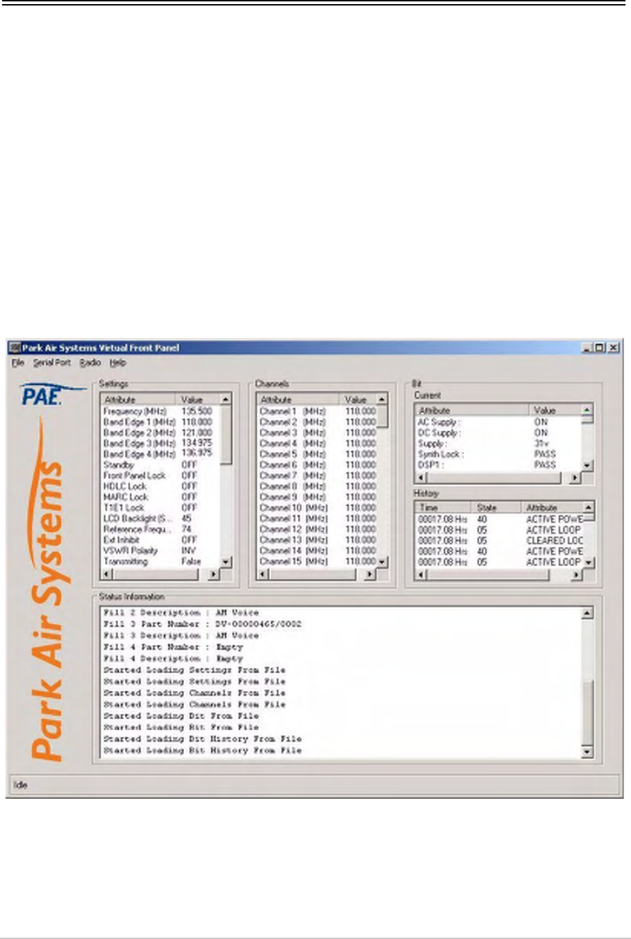
T6T 300 Watt VHF Transmitter Page 126 Maintenance
Virtual Front Panel (VFP)
Virtual Front Panel (VFP) software is supplied on CD and is compatible with any PC or laptop running
Windows 2000™ or Windows XP™. The VFP allows changes to a radio’s settings and channel
information, it displays the current BIT state, displays BIT history, allows security locks to be set, and
provides maintenance facilities.
A radio can be set up using the front panel Scroll/Select switch and LCD, or by using the VFP. Using the
VFP has several advantages over setting the drive assembly from the front panel; these are:
❑A profile of the drive assembly operation settings and channel information can be created, stored
on disk, and then recalled to download into other drive assemblies
❑A printout of the drive assembly profile can be made from the VFP
❑Front Panel Lock is available only when using the VFP. As part of the drive assembly Settings
(see Fig 31), Front Panel Lock can be set to ON. When selected to on, no settings or frequency
information can be changed from the front panel
❑If the drive assembly is part of a MARC system or operates in a digital mode, a MARC Lock, HDLC
Lock and T1E1 Lock are available when using the VFP. When selected to on, no settings or
frequency information can be changed from the MARC equipment screen, or the digital control
equipment.
Fig 31 Typical VFP Screen - AM-Voice Profile Shown

T6T 300 Watt VHF Transmitter Page 127 Maintenance
Installing the VFP Software
The VFP software is supplied by Park Air on CD. The software can be run from the Main page or installed
on your PC via Explorer.
To install the software onto your PC:
(1) Using explorer, display the contents of the CD supplied by Park Air. Identify the file named
S0473Vxx.EXE (where xx is the version number).
(2) Using the mouse, right click on the file and then select Copy.
(3) Display the Windows desktop. Right click anywhere on the desktop and select Paste.
(4) Check that the VFP icon is shown on the desktop. Reposition the icon as required. The VFP
application is now installed on the PC’s desktop.
VFP Icon
VFP Features
The VFP screen is divided into four main windows: Settings, Channels, BIT and Status Information. Four
colours are used to display text. The colours have the following meanings:
❑Black indicates a valid parameter that has been accepted by the radio
❑Red indicates an invalid parameter that has been rejected by the radio, or a BIT failure
❑Green indicates text that has not yet been downloaded to the radio. Text loaded into the VFP from
a previously stored file, or any text that is manually amended is green until it is downloaded into
the radio; after being downloaded into the radio the text changes to black, or if it is invalid, to red
❑Blue indicates Help text and is shown in the Status Information window.
The Menu Bar
The menu bar has four categories: File, Serial Port, Radio and Help.
File Has the sub-categories: Open, Save and Print. These sub-categories allow the user to
open previously saved profiles, save a new profile, or print a profile.
A special sub-category: File > Save > Diagnostics should only be used when advised by
Park Air.
Serial Port Has the sub-categories: Com 1 and Com 2. Before the VFP can be used, the appropriate
Com 1 or Com 2 must be selected to correspond with the PC’s Com Port used for the
radio connection.
Radio Has the sub-categories: Retrieve, Send, Calibrate and Test. These sub-categories allow
a radio’s profile to be loaded into the VFP, allow a profile to be downloaded from the VFP
to a radio, calibrates a radio and initiates a BIT test.
Help Provides detail about the VFP software.

T6T 300 Watt VHF Transmitter Page 128 Maintenance
Settings Window
This window lists all attributes that can be adjusted by the user. If any individual attribute is clicked on
using the mouse, help information is displayed in the Status Information window showing the range of
adjustment for that attribute. Click on the value and use the keyboard to amend it; press Enter to confirm
the new value noting that the amended text is green until it is downloaded into the radio. Any invalid
parameters are not indicated until the Settings are downloaded to the radio. It is the radio that rejects
invalid parameters, not the VFP.
The drive assembly reference frequency setting is displayed in the window. Adjusting the reference
frequency is a maintenance operation that requires external test equipment to be connected. The value
shown in the Settings window should not be changed; instead, adjustment of the reference frequency
should be performed using the radio front panel controls as detailed on page 100.
Channels Window
Up to 100 preset channels can be stored in the radio. These are listed in the Channels window. Any
channel frequency can be amended by clicking on the value to amend it and pressing Enter to confirm
the new value. Note that the amended channel is green until it is downloaded into the radio. Any invalid
frequencies are not indicated until the Channels are downloaded to the radio. It is the radio that rejects
invalid frequencies, not the VFP.
BIT Window
Two lists of information are presented: The current BIT status and the BIT history. The BIT history shows
the last 100 entries.
Status Information Window
The Status Information window gives information regarding the type of radio, the software fills, recent
VFP actions and Help information.
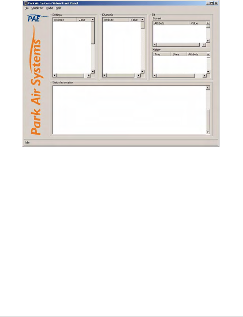
T6T 300 Watt VHF Transmitter Page 129 Maintenance
To Change the Drive Assembly Profile or Save a Profile
(1) Using a PC to Radio Interconnection Lead, Park Air part number 17E12600001, connect the
drive assembly’s front panel Microphone/Diagnostics connector to the PC’s Com Port 1 or Com
Port 2 (note which Com Port is used).
(2) Run up the VFP software and check that a blank VFP screen (see Fig 32) is displayed.
Fig 32 Blank VFP Screen
(3) At the Menu Bar, click on Serial Port and select either Com 1 or Com 2. The selection must
correspond to the port used to connect to the radio.
(4) Load the required information from the radio, or from a stored file. The required information can
be radio settings, frequency channels, BIT information, or all of these.
To load a previously stored file, select File > Open > All
or, File > Open >Settings
or, File > Open > Channel
or, File > Open > BIT
To load information from the radio, select Radio > Retrieve > All
or, Radio > Retrieve > Settings
or, Radio > Retrieve > Channel
or, Radio > Retrieve > BIT
(5) If required, amend any radio Settings or Channel information.

T6T 300 Watt VHF Transmitter Page 130 Maintenance
(6) Download the radio’s profile as shown on the VFP screen to either the radio, or to a file.
To download into the radio, select Radio > Send > All
or, Radio > Send > Settings
or, Radio > Send > Channel
To download to a file, select File > Send > All
or, File > Send > Settings
or, File > Send > Channel
or, File > Send > BIT
(7) Check that after downloading to a radio, no invalid parameters are returned (such parameters
are displayed as red text). If there are invalid parameters, amend them and then repeat the
download.
(8) When there is no further requirement for using the VFP, exit the VFP software and disconnect
the radio from the PC.
To Initiate a BIT Test
(1) Using a PC to Radio Interconnection Lead, Park Air part number 17E12600001, connect the
radio’s front panel Microphone/Diagnostics connector to the PC’s Com Port 1 or Com Port 2
(note which Com Port is used).
(2) Run up the VFP software and check that a blank VFP screen is displayed.
(3) At the Menu Bar, click on Serial Port and select either Com 1 or Com 2. The selection must
correspond to the port used to connect to the radio.
(4) At the Menu Bar select Radio > Test.
(5) An interruptive BIT test now takes place. The results are displayed in the BIT window.
(6) If there is no further requirement for using the VFP, exit the VFP software and disconnect the
radio from the PC.
To Calibrate the Transmitter
(1) Connect a suitable dummy load via a power meter to the combiner’s Antenna connector.
(2) Remove the drive assembly’s bottom cover.
(3) Using a PC to Radio Interconnection Lead, Park Air part number 17E12600001, connect the front
panel Microphone/Diagnostics connector to the PC’s Com Port 1 or Com Port 2 (note which
Com Port is used).
(4) Run up the VFP software and check that a blank VFP screen is displayed.
During an interruptive BIT test, the transmitter radiates modulated carrier waves at the set power.
Users should therefore obtain the necessary authority before initiating a test.
If the test is to be carried out with the antenna disconnected, ensure a load is fitted to the
transmitter's Antenna connector.
In order to test the line input stages, an internally generated 1 kHz tone is injected into the line input
circuit. Any other audio present on the line input will cause the test to be inaccurate. Therefore the
transmitter MUST NOT be keyed during the test.
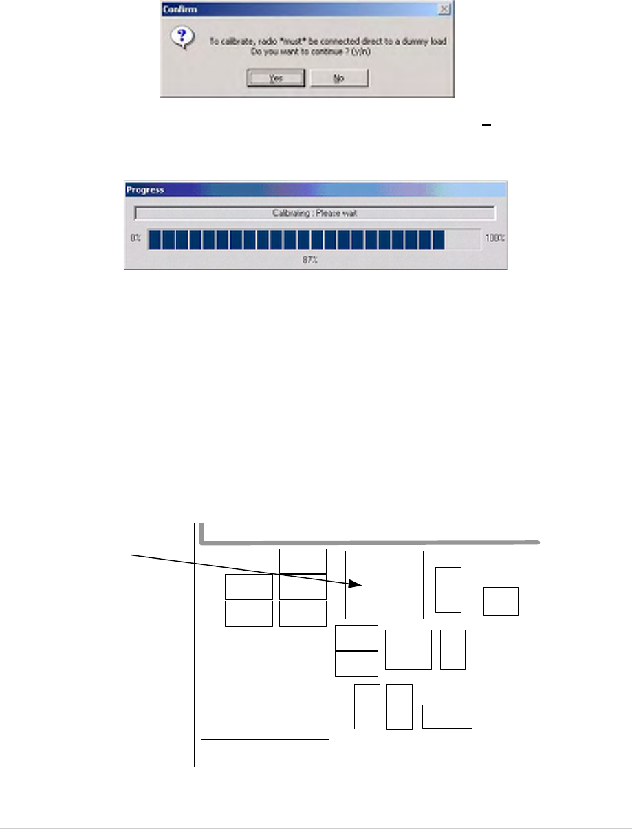
T6T 300 Watt VHF Transmitter Page 131 Maintenance
(5) At the Menu Bar, click on Serial Port and select either Com 1 or Com 2. The selection must
correspond to the port used to connect to the radio.
(6) At the Menu Bar select Radio > Retrieve > All.
(7) At the Menu Bar select Radio > Calibrate. The Confirm screen will then be displayed to remind
you that a dummy load must be connected before proceeding.
(8) With the Confirm screen displayed and dummy load connected, select Yes to continue with the
calibrate routine. The Progress screen will then be displayed.
(9) When the PA Control/PA loop has been calibrated the Progress screen disappears and the VFP
screen reappears showing a calibration complete message in the Status Information window.
(10) Gain access to the PA Control module and identify RV8 (see Fig 33). From the drive assembly’s
front panel AM-Voice or AM-MSK Settings screen, select PTT On.
(11) From the Settings window of the VFP screen, note the RF power setting. Adjust RV8 until the
power meter reads this value.
(12) From the drive assembly’s front panel AM-Voice or AM-MSK Settings screen select PTT Off,
then remove the power meter and dummy load. This completes the calibration routine.
(13) When there is no further requirement for using the VFP, exit the VFP software and disconnect
the radio from the PC and refit the bottom cover.
Location of RV8
Fig 33 Location of PA Control Module RV8
R130
R131
R125
C421
R135
RV8
CN4
R455
R456
C424
R348
D24
R231
R382 R243
TP10
RV8
Intentionally Blank
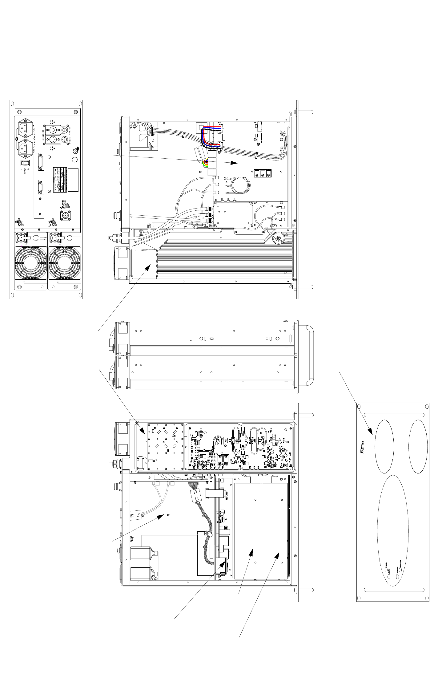
Fig 34 T6T VHF Amplifier Module Location Diagram
Top View Bottom View
Combiner BIT Module
Interface Module
PSU Regulation Module
Power Supply Modules
PA Modules
Front Panel Assembly
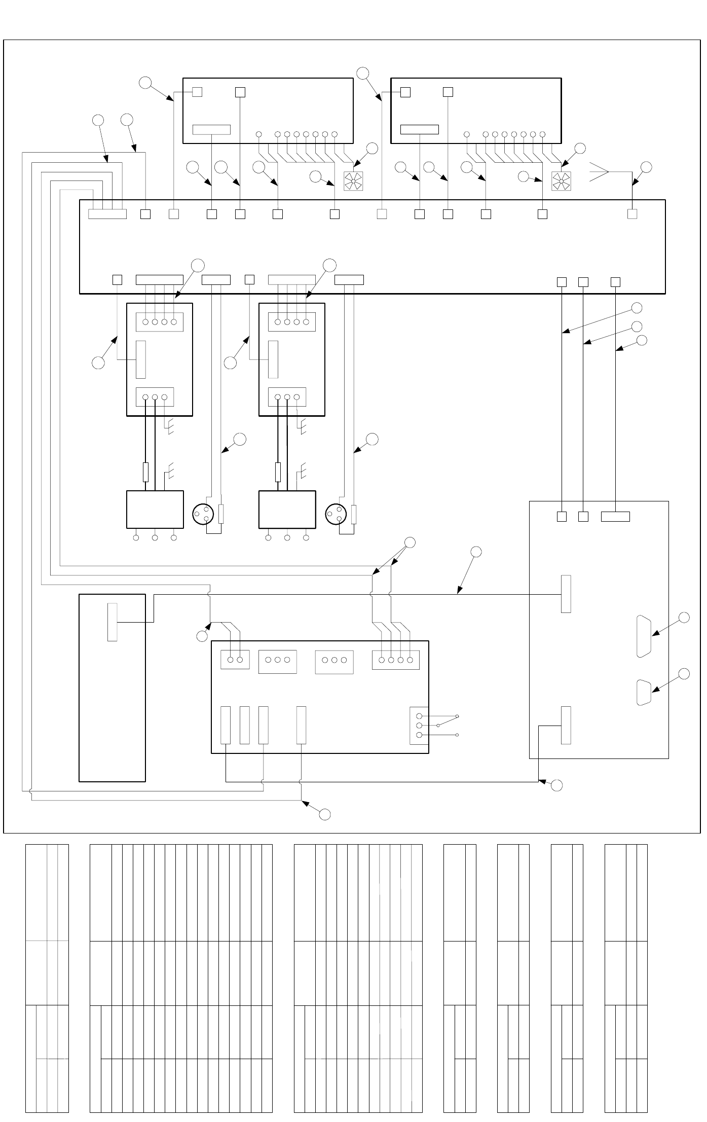
CN6 CN7
FacilitiesMARC
Front Panel assembly
CN1
CN5CN6
Interface module
CN24
(Rear Panel)
CN3
CN4
CN2
PSU-2
CN1
L
N
E
CN4
ac Input
(Rear Panel)
L
N
E
Mains IEC
connector
filtered/
fused
PSU-1
CN1
L
N
E
CN4
ac Input
(Rear Panel)
L
N
E
Mains IEC
connector
filtered/
fused
CN12
CN7
CN15
CN27
CN16
CN4
CN3
CN1
CN10
CN11
CN2
CN4
CN5
Power Supply
Regulation
CN3
(Rear Panel)
CN7
CN6
Supply shown in
off position
132
CN2 1
2
1
3
2
CN1
4
CN8
1L
2N
3E
CN9
21
dc Input - 1
dc Input - 1dc Input - 1
dc Input - 1
(Rear Panel)
3
21
dc Input - 2
dc Input - 2dc Input - 2
dc Input - 2
(Rear Panel)
3
Combiner BIT
module
Fan
CN13
CN5
CN26
CN17
CN22
CN10
CN1
CN8
CN2
CN4
CN5
CN7
CN9
CN6
CN12
PA-1
CN3
CN14
CN6
CN25
CN18
CN23
Fan
CN10
CN1
CN8
CN3
CN2
CN4
CN5
CN7
CN9
CN6
CN12
PA-2
1L
2N
3E
7 8
24
17
17 19
20
20
11
12
13
14
15
11
12
13
14
15
16
31
9
10
10
6
19
26
18
17
17
(Rear Panel)
18
Interface MARC Port
Name Characteristic
Connections 1
FacilitiesInterface
Connections 3Name Characteristi c
7
5
6
4
2
3
1
9
8
14
15
13
12
11
10
CN5-4
CN5-6
CN5-7
CN5-5
CN5-3
CN5-2
CN5-1
CN5-8
CN5-9
CN5-14
CN5-15
CN5-13
CN5-12
CN5-11
CN5-10
PA Bias Enable
Reflected Power
Fan Enable
PA Temperature
Drive Detect
PA Count
Connections 6Name Characteristi c
50 W = 670 mV
TTL - High for fan on
TTL - High for bias on
10 mV / °C +0.5 V
0.5 V for +10 dBm
TTL, Pulse width = 10 ms/50 W PA
Forward Power Sense CN27-1 17 dBmCN4-1
Interface
Connections 7Name Characteristic
Interface
1 dBm carrierRF DriveCN3-1CN16-1
Connections 8Name Characteristic
RF Output
PA
CN24-1 10 to 100 WAntenna Port
Connections 9Name Characteristic
Combiner BIT module
CN15-1
CN15-5
CN15-4
CN15-3
CN15-2
CN15-6
CN2-3
CN2-5
CN2-4
CN2-6
CN2-2
CN2-1
Interface
PA Heatsink
CN6 Fan Control
Ground 0 V
10 V approx or 26.5 VFan
Fan
PA-1 PA-2
Connections 10 Name Characteristic
PTT
Reflected Power
Fan Enable
PA Temperature
Drive Detect
50 W = 670 mV
TTL - High for fan on
TTL - High for bias on
10 mV / °C +0.5 V
0.5 V for +10 dBm
TX Key TTL - High for PA Keyed
Present +5 V
Fail 3 TTL Low to indicate failure
Ground 0 V
Remote on/off
DC Detect
AC Detect
Open collector
15 Von,0 Voff
0V=off,opencollector=on
n/c n/c
n/c n/c
n/c n/c
Forward Power Sense 17 dBm
1 dBm carrierRF Drive
Combiner BIT module
Combiner BIT module
Ground 0 VCN15-7 CN2-7
Combiner Supply Unreg current limited at 250mACN15-8 CN2-8
PA-1 Fail Indication TTL, 0 V = fail
CN15-9 CN2-9
CN15-10 CN2-10 PA-2 Fail Indication TTL, 0 V = fail
(Rear Panel)
1
2
CN8-1
CN8-2
Fig 35 T6T VHF Amplifier Wiring and Interconnection Diagram

Fig 36 T6T VHF Amplifier Wiring List
Connections 18 Name Characteristic
PSU-1 PSU-2
dc OK
Ground
PSU off
CN4-2
CN4-1
CN4-3
0 V = off
TTL, high = PSU on
0 V
Connections 17 Name Characteristic
CN7-6
CN7-7
CN7-8
CN7-2
CN7-4
CN7-3
CN7-5
CN7-1
Regulation
Pin Diode - ve
V Unregulated
n/c
AC Derived Supply
DC Derived Supply
Ground
Ground
Ground 0 V
29 V
21.6 V to 32 V
0 V
-30 V to -35 V
CN3-2
CN3-1
n/c
CN1-3 & 4
CN2-2
CN2-1
CN3-3
CN1-1 & 2
21.6 V to 32 V
0 V
n/c
Connections 19 Name Characteristic
PSU-1 PSU-2
CN1-1
CN1-6
CN1-5
CN1-2
Ground Supply
V Unreg
Ground Supply
V Unreg
0 V
0 V
29 V
29 V
0 V
0 V=on
o/c okPSU ok
0 V
PSU off
Regulation
0 V
PSU ok
0 V
0 V ok
PSU off 0 V=off
Name Characteristic
Connections 16
CN6-3
CN6-5
CN6-4
CN6-6
CN6-2
CN6-1
CN12-3
CN12-1
PA-1 PA-2
1 dBm carrierRF DriveCN10CN17-1 CN18-1
Connections 14 Name Characteristic
RF Output
PA-1 PA-2
CN1-1 5 to 50 WCN22-1 CN23-1
Connections 15 Name Characteristic
Input-1 CN2-2 Fused 21.6 V to 32 VDc Input
Input-2 CN2-1 Ground Supply 0 V
DC Input-1, DC Input-2 Regulation
Input-3 n/c n/c
Name Characteristic
Connections 20
CN3-14
CN3-13
CN3-12
CN3-11
CN3-10
n/c
Remote on/off
V Unreg
DC Detect
CN3-9
CN3-8
CN3-7
CN3-6
CN3-5
CN3-4
CN3-3
CN3-2
CN3-1
AC Detect
-15 V Supply
Ground
+5 V Supply
+15 V Supply
+15 V Supply
-15 V Supply
+5 V Supply
Ground
-15 V
21.6 to 32 V
21.6 to 32 V
Open collector
15 V on, 0 V off
+15 V
+5 V
+15 V
-15 V
+5 V
0 V
0 V
0 V=off, open collector=on
n/c
ProcessorRegulation
Connections 26 Name Characteristic
CN4-1
CN4-2
CN4-3
CN4-4
CN4-5
CN4-6
CN4-7
CN4-8
CN4-9
CN4-10
CN4-11
CN4-12
CN4-13
CN4-14
V Unreg
PA Bias EnableCN13-3 CN14-3
CN13-5 CN14-5
CN13-4 CN14-4
Reflected Power
Fan Enable
PA-1 PA-2
CN13-6 CN14-6
CN13-2 CN14-2
CN13-1 CN14-1 PA Temperature
Drive Detect
CN4
CN9
CN5
CN7
CN2
CN12 PA Count
Connections 11 Name Characteristic
50 W = 670 mV
TTL - High for fan on
TTL - High for bias on
10 mV / °C +0.5 V
0.5 V for +10 dBm
TTL, PW = 10 ms/50 W PA
CN3-1CN5-1 CN6-1 V Unreg 21.6 V to 32 V
Connections 12 Name Characteristic
CN3-2CN5-2 CN6-2
PA-1 PA-2
-33 V -30 V to -35 V
Forward Power Sense 17 dBm ±1 dB (-30.5 dBc ± 0.9 dB)
Connections 13 Name Characteristic
CN25-1 CN26-1 CN8
PA-1 PA-2
CN10-2 CN11-2
CN10-1 CN11-1
CN10-3 CN11-3
CN1-3 CN3-3
CN1-2 CN3-2
CN1-1 CN3-1
CN1-4 CN3-4
CN3-3CN5-3 CN6-3 Ground Supply 0 V
CN12-3
CN12-6
CN12-4
CN12-5
0 V
Ready LED
0 V
TX LED
Interface Front Panel
0 V
Alarm LED
0 V
Open Collector, 21 mA maximum
+15 V +15 V
Name Characteristic
Connections 24
CN7-3
CN7-1
CN7-2
CN7-6
CN7-4
CN7-5
CN7-7
CN7-8
CN7-9
CN7-10
CN1-3
CN1-1
CN1-2
CN1-6
CN1-4
CN1-5
CN1-7
CN1-8
CN1-9
CN1-10
n/c n/c
n/c n/c
n/c n/c
n/c n/c
Open Collector, 21 mA maximum
Open Collector, 21 mA maximum
Combiner BIT module
Combiner BIT module
Combiner BIT module
Combiner BIT module
Combiner BIT module
Combiner BIT module
Combiner BIT module
Combiner BIT module
Combiner BIT module
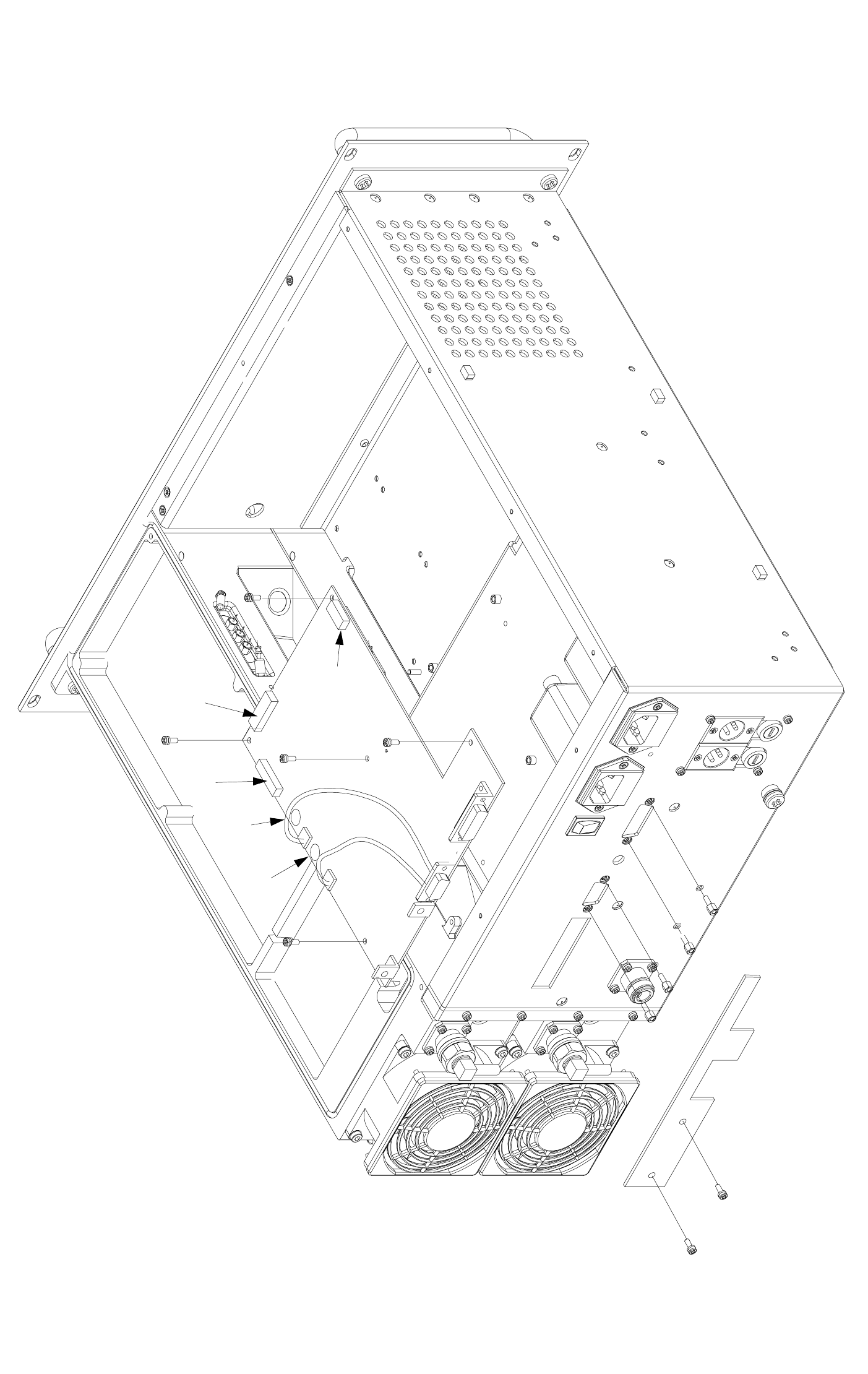
Fig 37 T6T VHF Amplifier Interface Module - Removal and Refitting Detail
CN6
CN7
CN3
CN4
CN2
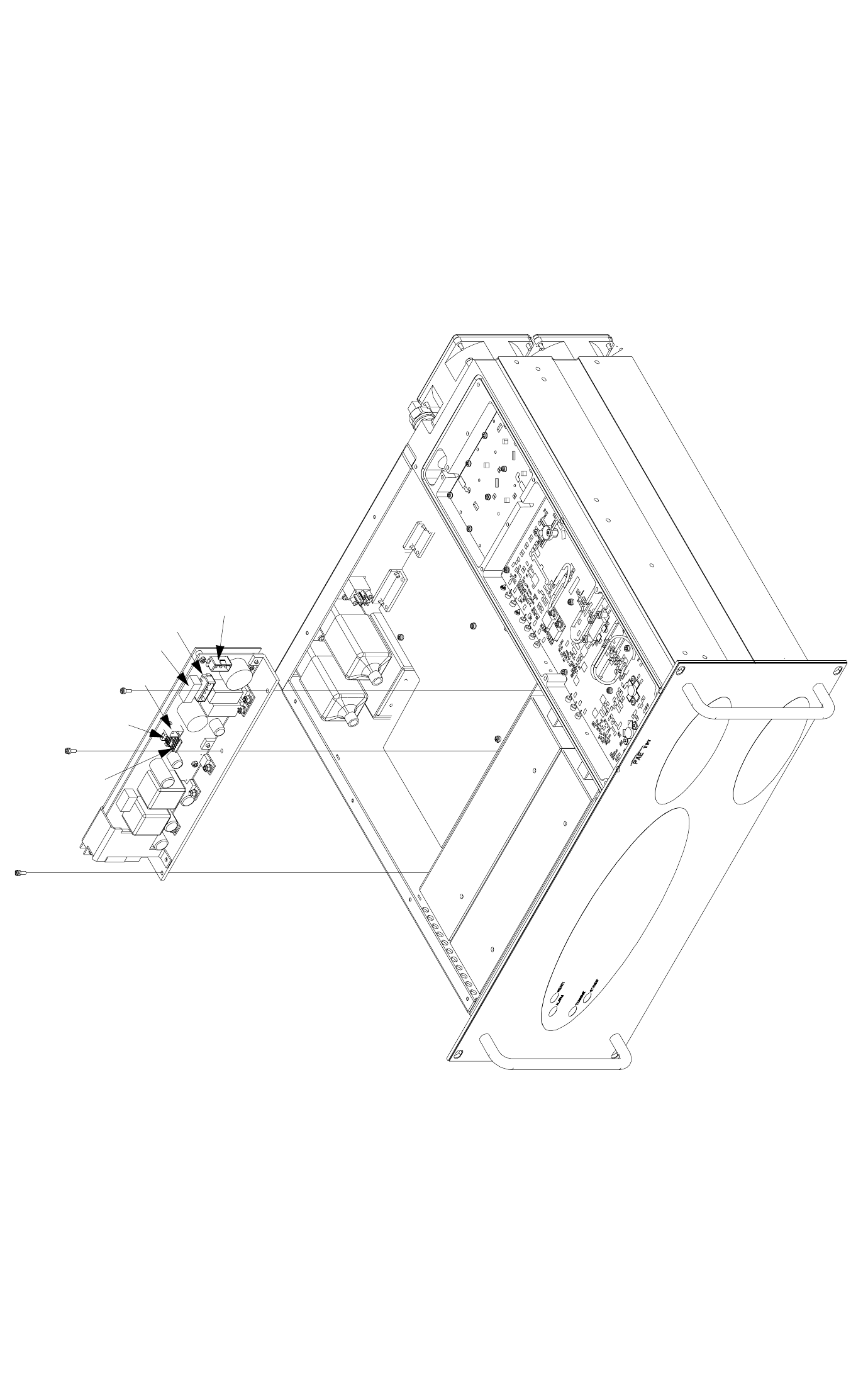
Fig 38 T6T VHF Amplifier PSU Regulation Module - Removal and Refitting Detail
CN3
CN1
CN4
CN2
CN7
CN6
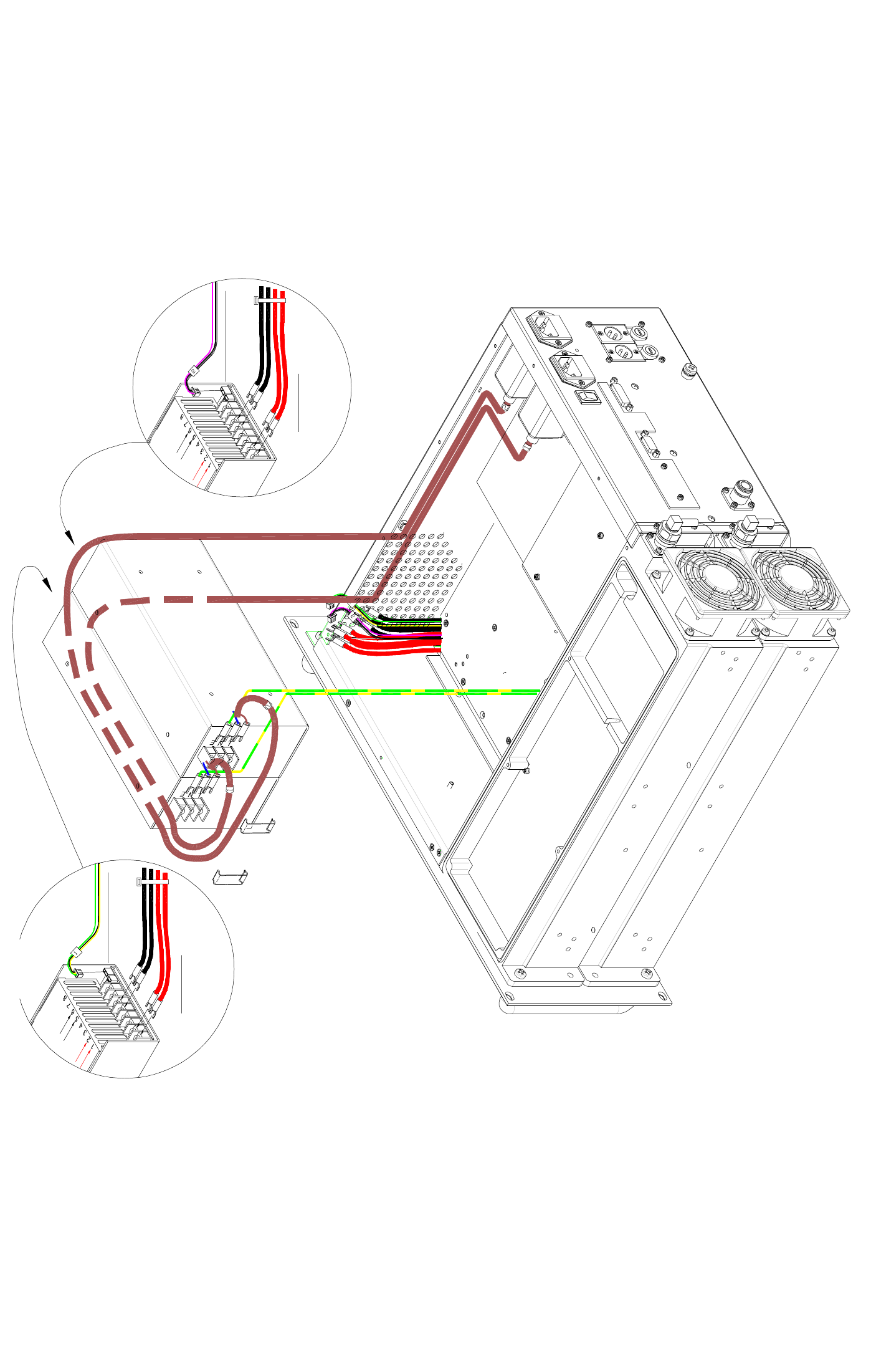
Fig 39 T6T VHF Amplifier Power Supplies - Removal and Refitting Detail
PSU to Bit Combiner (dc Connections)
Bit Combiner to PSU (fan control)
PSU to Bit Combiner (dc Connections)
Bit Combiner to PSU (fan control)
PSU-2 PSU-1
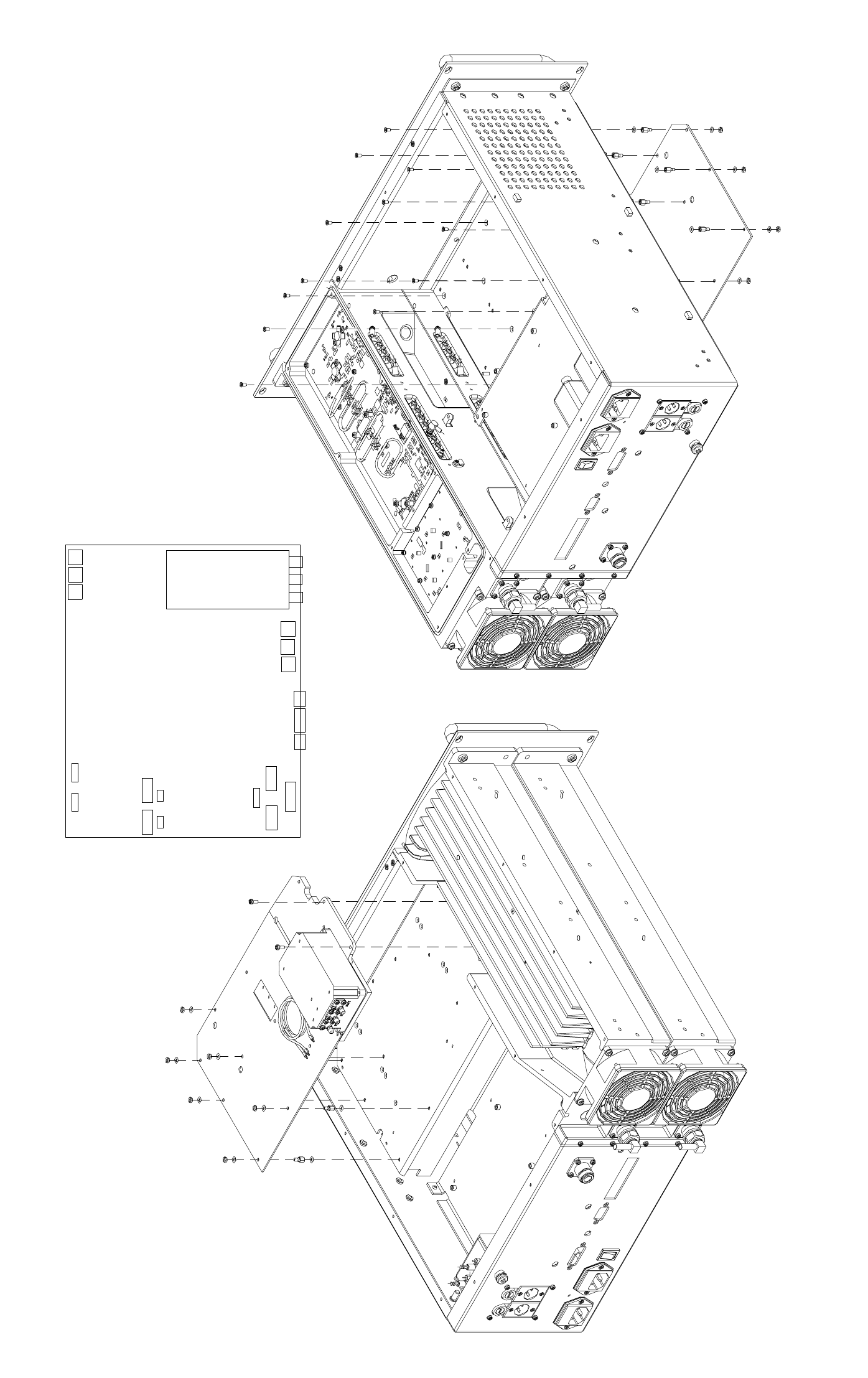
Fig 40 T6T VHF Amplifier Combiner BIT Module - Removal and Refitting Detail
CN5 CN6
CN7
CN12
CN15
CN14 CN13
CN26
CN25CN27
CN1 CN3
CN11CN10
CN2 CN4
CN22
CN23
CN24
CN18
CN17 CN16
Connector
Locations
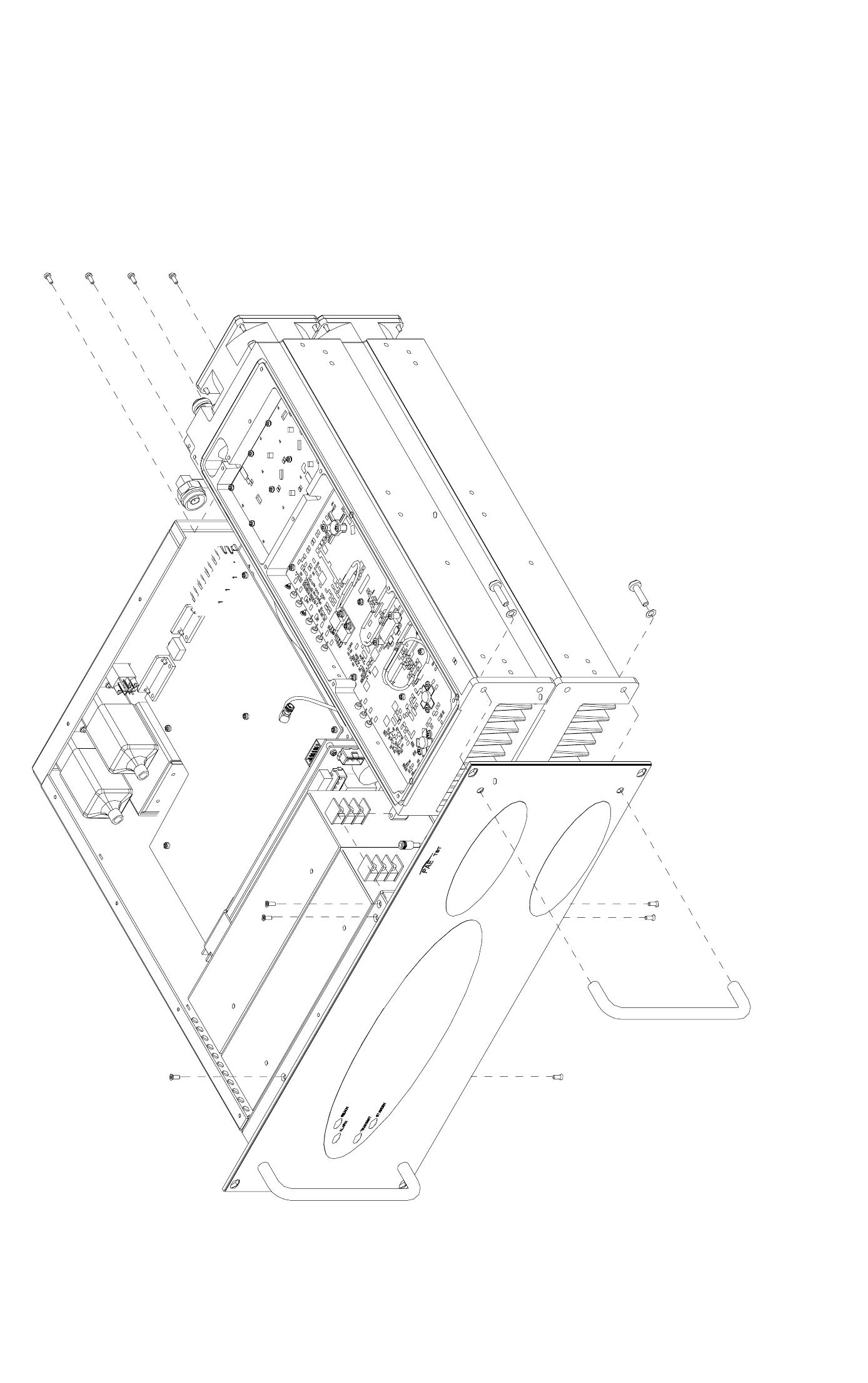
Fig 41 T6T VHF Amplifier PA Modules - Removal and Refitting Detail
PA-1
PA-2
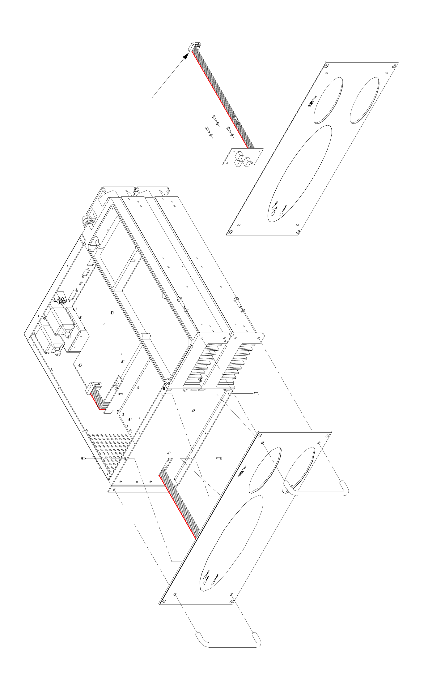
Fig 42 T6T VHF Amplifier Front Panel PCB - Removal and Refitting Detail
To Interface module CN7
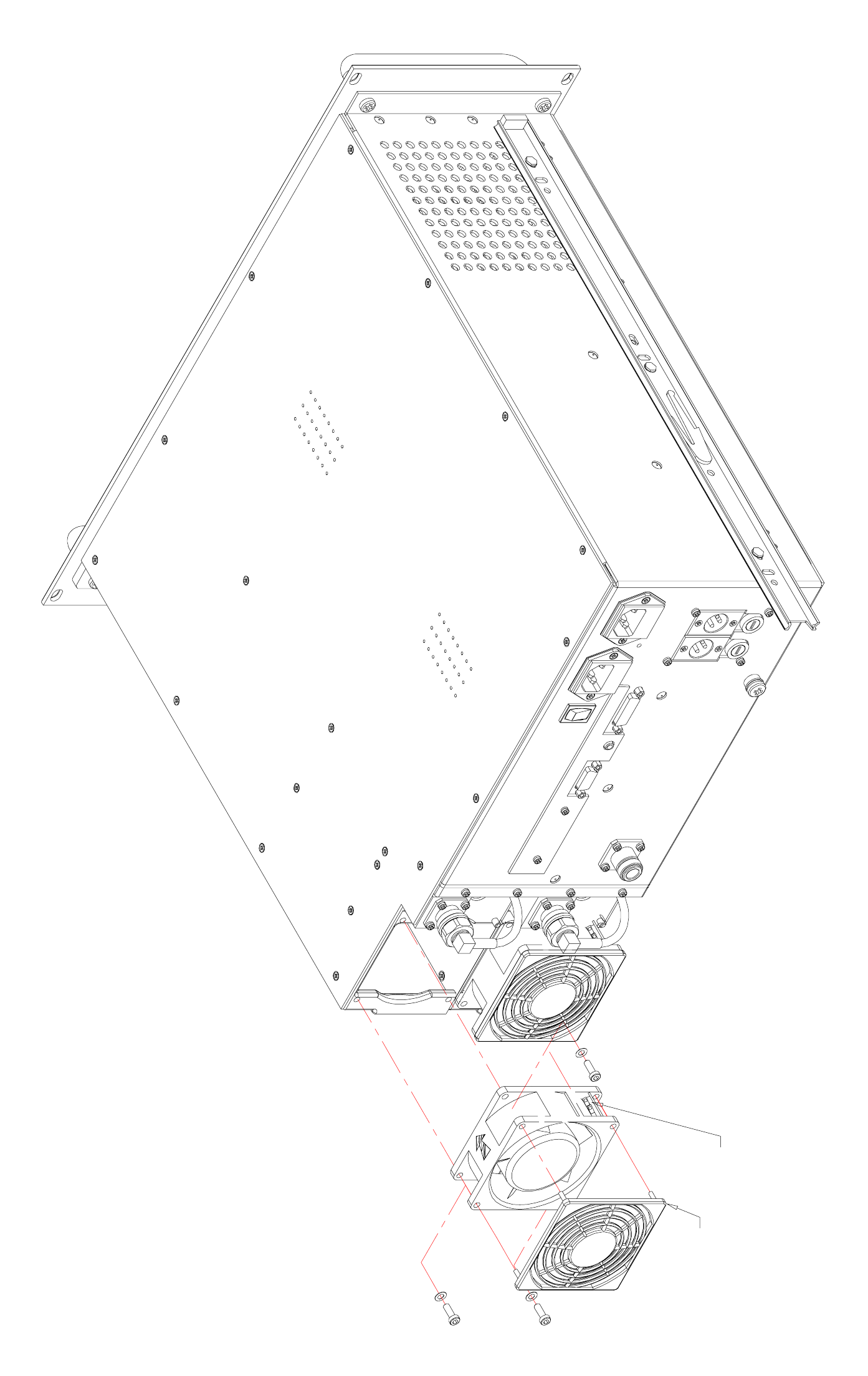
Fig 43 T6T VHF Amplifier Cooling Fans - Removal and Refitting Detail
power connections here
Finger guard
AIRFLOW
Finger guard
Power connections here
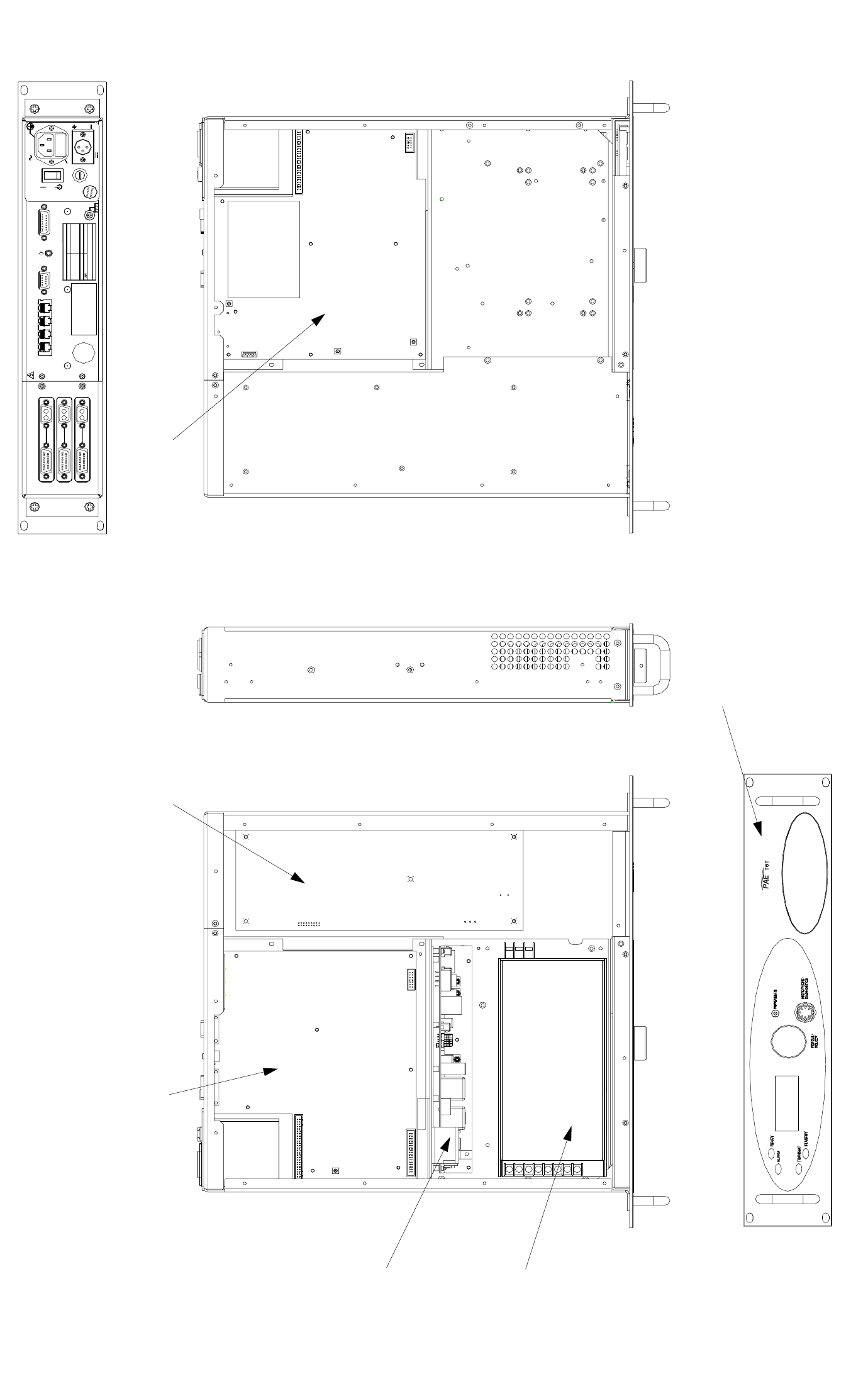
Fig 44 T6T VHF Drive Assembly Module Location Diagram
MAR C
HDLCT1/E1
ANTENNA
DANGER HIGH
RF VOLTA GES
CONNECT
ANTENNA
BEFORE
USE
AMPLI FIER OUT
AC SUPPLY
SUPPLY
FUSE F1
FUSE F2
DC SU PPLY
FUSE F2
RATINGS
110- 240 V T4A 250 V IEC
110 V - 12 0V T 4A 125V U L
F15A 32V
FUSE F1
48 - 62 Hz
AC SUP PLY
DC SUPPLY
DISCONNECT SUPPLIES WHEN NOT IN U SE
C ONNEC TING SUPP LI ES
SEE IN ST ALL AT ION I NSTRUC TIONS B EF ORE
~ 110 - 240V ( +10%) 4A
POWER 400VA max
21.6 - 32V 10A
FACILITIESMARC
AUDIO
MARC
DATA
Front Panel Assembly
Processor Module Drive Module
Top View Bottom View
PA Control Module
Power Supply
PSU Regulation Module
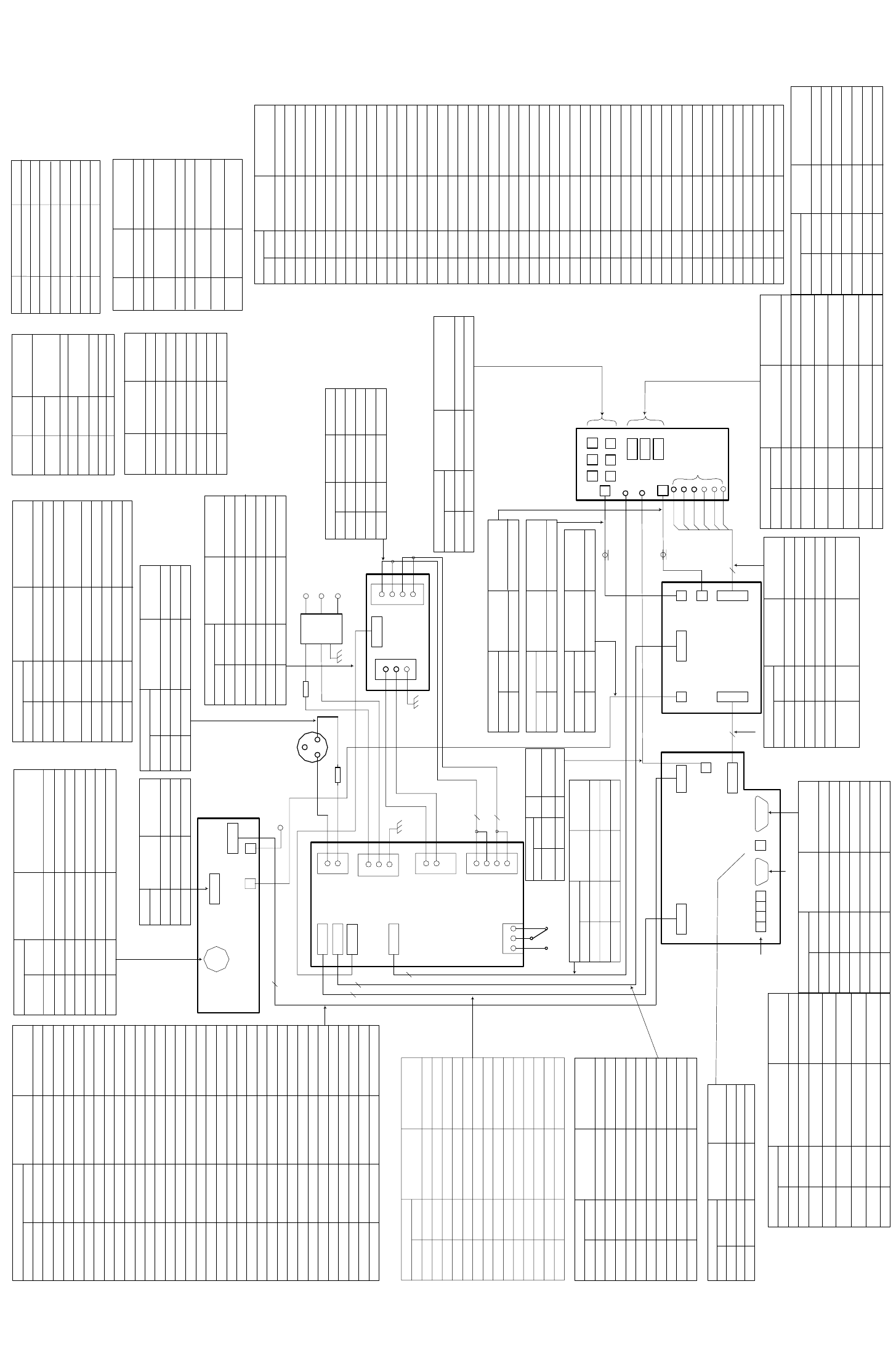
Fig 45 T6T VHF Drive Assembly Wiring and Interconnection Diagram
Microphone/Diagnostics
Front Panel assembly
CN3 CN1
Microph
one/
Front Panel
Connections Name Characteristic
CN2-1 1 Ground - Microphone 0 V
CN2-6
2 Transmit Data RS232
CN2-3 3 MIC PTT
CN2-4 4 Receive Data RS232
CN2-5 5 Sidetone (Headset Drive) 3 Vac pk-pk, 200R
CN2-2
6Microphone Input
CN2-7 7 Ground 0 V
CN4
CN5
Power
Supply
Regulation
CN2
1
2
2
3
1
CN3
1
3
2
CN1
4
dc Input
CN2-2 Fused 21.6 to 32 V
dc Input
Input-2 CN2-1 Ground Supply 0 V
Connections
DC Input Regulation Name Char acteristic
Input-3 n/c
Micr ophone/
Diagnostics
L
N
E
ac Input
CN1-1
CN1-6
CN1-5
Regulation
CN1-3
CN1-2
CN1-1
PSU
Connections
Ground Supply
Name Characteristic
CN1-4
0 V
CN3 CN4
CN7
Facilities
CN5
MARC
CN6
50
CN6
CN5
CN1
Processor module
PA Control
module
Connections
CN12-1
Processor
Characteristic
Name
Front Panel
Processor
Connections Name Characteristic
CN4-1
CN4-2
CN4-3
CN4-4
CN1-1
CN1-2
CN1-3
CN1-4
LED Alarm
LED Ready
LED Standby
LED Tx
LCD RS
Open collector (5 mA)
CN4-5
CN4-6
CN4-7
CN4-8
CN4-9
CN4-10
CN4-11
CN4-12
CN4-13
CN4-14
CN4-16
CN4-17
CN4-18
CN1-20
CN1-19
CN4-15
CN1-25
CN4-24
CN4-23
CN1-22
CN1-21
CN1-5
CN1-24
CN1-23
CN1-16
CN4-19
CN4-22
CN4-21
CN4-20
CN1-18
CN1-17
CN1-6
CN1-7
CN4-25
LCD R/W
LCD Backlight
Transmit Data
+5 V Supply
-5 V Supply
Ground
+15 V Supply
Ground
Mic PTT
LED RX (not used)
5 V pull-up
TTL
TTL
TTL
TTL
0 V
-5 V
TTL
TTL
+15 V
LCD Enable
Data 3
Data 2
Data 7
Data 6
Data 5
Data 4
RS232
+5 V
0 V
34
CN3-14
CN3-13
CN3-12
CN3-11
CN3-10
CN4-14
CN4-13
CN4-12
CN4-11
CN4-10
n/c
Remote on/off
V Unreg
V Unreg
dc Detect
CN3-9
CN3-8
CN3-7
CN3-6
CN3-5
CN3-4
CN3-3
CN3-2
CN3-1
Connecti ons
CN4-6
CN4-9
CN4-8
CN4-7
CN4-5
CN4-4
CN4-3
CN4-2
CN4-1
Regulation
ac Detect
-15 V Supply
Ground
+5 V Supply
+15 V Supply
Proce
ssor
Name Characteristic
+15 V Supply
-15 V Supply
+5 V Supply
Ground
-15 V
21.6 to 32 V
21.6 to 32 V
Open collector
15 V on, 0 V off
+15 V
+5 V
+15 V
-15 V
+5 V
0 V
0 V
CN6-7
CN6-6
CN6-10
CN6-9
CN6-8
CN5-10
CN5-9
CN5-6
CN5-7
CN5-8
-15 V Supply
ac Detect
dc Detect
-15 V Supply
Ground
-15 V
-15 V
0 V
Connections
CN6-5
CN6-4
CN6-3
CN6-2
CN6-1
CN5-2
CN5-4
CN5-3
CN5-5
Regulation
CN5-1
Name
+5 V Supply
+15 V Supply
+5 V Supply
+15 V Supply
Ground
PA Control
Characteristic
+15 V
+5 V
+5 V
0 V
+15 V
*
*
CN6-7 7
CN6-8
CN6-9 9
8
Processor
CN6-1
CN6-2
CN6-3
CN6-5
CN6-6
CN6-4
**
4
6
5
3
1
2
MARC Port
Connections
Data RX A - Data In - RS422
RS422
RS422
Data TX B - Data Out +
Data TX A - Data Out -
RS422
0 V or +10 V to +60 V or
Fused 500mA, 21.6 to 32 V
+20 dBm to -20 dBm 600R
Characteristic
PTT Input
Data RX B - Data In +
Unregulated Supply
Line In +
Ground 0 V
Name
+20 dBm to -20 dBm 600R
**
CN5-4
CN5-6
CN5-7
CN5-5
7
5
6
4
Grounding output +/- 60V,
100 mA maximum
TTL pull-up active low
Grounding output +/- 60V,
100 mA maximum
Squelch Defeat (not used)
Antenna Change-over
External VSWR
CN5-3
CN5-2
CN5-1
Processor
Connections
Facilities
2
3
1
TTL pull-up active low
Characteristic
Name
E Bit
PTT
Ground 0 V
Ground
Unregulated Supply
CN5-8
CN5-9 9
80 V
Fused 300 mA 21.6 to 32 V
Groundi ng output +/- 60 V,
100 mA maximum
Reserved
Tape OutputCN5-14
CN5-15
CN5-13
CN5-12
CN5-11
14
15
13
12
11 BIT Interruptive Test
RSSI (not used)
Ready Output
Facilities
Connections
CN5-10
Processor
10 Inhibit
Open collector, 0 V=Ready
-10 dBm. 100R
TTL pull-up active low
Characteristic
***
V Unreg
Receive Data
0 V=PTT, 5 V pull-up=PTT
Turn +
TTL
TTL
TTL
RS232
Turn -
Sidetone (Headset Drive) 3 Vac pk-pk
Loudspeaker Amp Drive
Ground
Mic Input
Ground 0 V
1.6 V pk-pk maximum
0 V
2 V pk-pk maximum
Push
Ground 0 V
CN1-26CN4-26
CN1-27CN4-27
CN1-31
CN1-29
CN4-28
CN1-30
CN4-31
CN4-29
CN1-28
CN4-30
CN4-33
CN1-34
CN1-33
CN4-34
CN1-32CN4-32
Open colle ctor (200 mA)
0V=off, open collector=on
n/c
n/c
n/c
n/c
n/c
CN2
CN1
CN3
CN4
CN2
CN3-2
Front Panel Characteristic
Ground
Connecti ons
Loudspeaker Output
Name
0 V = PTT, 5 V pull-up = not PTT
6k8 input impedance, 5 mV sensitivity
CN7
6
Drive
module
Reference Frequency
Connections
Front Panel
-20 dBm to 0 dBm
Characteristic
Name
CN5-1
Forward Power Sense
CN9
Connections
17 dBm ± 1 dB
Name Characteristic
Drive Name Characteristic
CN4-1
(Rear Panel)
CN9
Open collector (5 mA)
Open collector (5 mA)
Open collector (5 mA)
Data 1
Data 0
TTL
TTL
CN1-12
CN1-13
CN1-14
CN1-15
CN1-8
CN1-9
CN1-10
CN1-11
5 V pull-up
5 V pull-up
Drive
1 dBm carrierRF DriveCN7CN3-1
Connections Name Characteristic
-10 V to -60 V at 6 mA
TTL pull-up active low
Name Characteristic
CN3-1
CN3-2
CN3-3 Heatsink
CN8 V Unreg
-33 V
Ground Supply
21.6 to 32 V
0 V
n/c
10
14
3
CN3-3 n/c n/c
CN5
CN4
Reference Frequency
(Front Panel)
CN4-1
CN8
CN10
(-30.5 dBc ± 0.9 dB)
Mains IEC
Connector
Filtered/
Fused
Frequency Trim
CN1-14 CN1-14
CN1-50
CN1-48
CN1-49
CN1-47
CN1-45
CN1-46
CN1-44
CN1-43
CN1-42
CN1-41
CN1-15
CN1-16
CN1-21
CN1-22
CN1-23
CN1-17
CN1-19
CN1-18
CN1-20
CN1-24
CN1-25
CN1-30
CN1-26
CN1-29
CN1-28
CN1-27
CN1-31
CN1-32
CN1-33
CN1-34
CN1-36
CN1-35
CN1-37
CN1-40
CN1-39
CN1-38
CN1-50
CN1-45
CN1-43
CN1-44
CN1-47
CN1-46
CN1-49
CN1-48
CN1-28
CN1-42
CN1-41
CN1-38
CN1-39
CN1-36
CN1-37
CN1-40
CN1-32
CN1-31
CN1-29
CN1-30
CN1-34
CN1-33
CN1-35
CN1-21
CN1-24
CN1-23
CN1-22
CN1-26
CN1-27
CN1-25
CN1-17
CN1-16
CN1-15
CN1-20
CN1-19
CN1-18
TTL
TTL
TTL
TTL
TTL - Low OCXO fitted
TTL - Hi gh fan on
TTL
BITControl3(not used)
BITControl2(not used)
Step Size (not used)
V/U Detect
TR Detect
Reserved
OCXO Fitted
Fan Enable
TTL
TTL
TTL
TTL
TTL
TTL
0 to 2.5 V
10 mV / °C
10 mV / °C
0 to 5 V (5 V, 3 dB back off)
TTL
TTL
TTL
TTL
TTL
BIT Loop Correct
BIT Synth Lock
BIT Open Loop
BIT VSWR OK
BIT Control 1
BIT Control 0
Reflected Power
PA Temperature
Auto Level Control
External VSWR
PAC Temperature
NB/WB (not used)
Tx Key
TTL
TTL
TTL
TTL
0 V
TTL
0 V
TTL pull up active low
TTL
TTL
TTL
TTL
Filter 3
Data
Phase Load
Clock
Synth Load
Ground
Filter 4
Filter 0
Filter 2
Filter 1
Ground
Power Down
Tx/Rx Detect
CN1-10
CN1-13
CN1-12
CN1-11
PA ControlProcessor
CN1-7
CN1-7
CN1-9
CN1-10
CN1-8
CN1-12
CN1-13
CN1-11
CN1-9
CN1-8
CN1-2
CN1-3
CN1-1
CN1-5
CN1-6
CN1-4
CN1-6
CN1-5
CN1-4
CN1-2
CN1-3
CN1-1
Connections
0 to 2.5 V
0 V
±2.5 V
±2.5 V
0 to 2.5 V
0 to 2.5 V
0 to 2.5 V
0 V
0 V
0 V
0 V
0 V
0 V
Ground
Ground
Q
Ground
Ground
BIT Q Monitor
BIT I Moni tor
RF AGC (Not used)
I
Ground
IF AGC (Not used)
Ground
Ground
Name Characteristic
***
A B C D
CN8
Processor
CN8 Ring
CN8 Tip External Speaker Drive
External Speaker Drive 3 Vac pk-pk maximum
Charact eristic
Connections Name
External Speaker
1
2
CN8 Sleeve Ground 0 V3
3 Vac pk-pk maximum
Antenna Change-over
TTL pull-up active low
Potential range 0 V to 10 V
6
7
8
2
4
3
5
Pin Number
1
Name
CN7A
n/c
n/c
n/c
RTIP
TRING
n/c
TTIP
RRING
*
6
7
8
2
4
3
5
Pin Number
1
Name
CN7B
HDLC CL B
HDLC CL A
Unregulated Supply
HDLC Rx B
HDLC Tx B
HDLC Rx A
HDLC Tx A
Ground
6
7
8
2
4
3
5
Pin Number
1
Name
CN7C
n/c
Unregulated Supply
Data Rx B (Data In +)
Data Tx B (Data Out +)
Data Rx A (Data In -)
Data Tx A (Data Out -)
Ground
*
6
7
8
2
4
3
5
Pin Number
1
Name
CN7D
Not used
Fast antenna
change-over/PTT
Not used
Line In +
PTT Input
Line In -
Not used
Ground
*
Characteristic
Characteristic
Characteristic
Characteristic
+20 dBm to -20 dBm 600R
+20 dBm to -20 dBm 600R
0 V
0 V or +10 V to +60 V or
-10 V to -60 V at 6 mA
+20 dBm to -20 dBm 600R
+20 dBm to -20 dBm 600R
ANSI T1.403-1995 (T1)
ITU-T: G.703 (E1)
ANSI T1.403-1995 (T1)
ITU-T: G.703 (E1)
NPN open collector
grounding transistor
0 V or +10 V to +60 V or
-10 V to -60 V at 6 mA
0 V
RS 422
RS 422
RS 422
RS 422
RS 422
RS 422
21.6 V to 32 V
Reserved
RF PA Bias Disable
TTL
0 V
7.5 V pk-pk maximum
Open collector (5 mA)
EXT SPKR
T1/E1
MARC AUDIO
MARC DATA
HDLC
TTL
Drive PA Control
PA Control
PA Control
0 V
21.6 V to 32 V
RS 422
RS 422
RS 422
RS 422
13
(Rear Panel)
CN7
2
Supply
(shown in
off position)
CN8
1 L
2 N
3 E
Power
Supply
CN1
L
N
E
CN6
CN1-2
CN4
CN9
L
N
PSU OK
CN6-3
CN6-5
CN6-4
0 V
PSU off
PSU
Regulation
Connections Name
CN6-6
CN6-2
CN6-1 0 V
PSU OK
0 V
0 V OK
CN4-3
CN4-1 PSU off PSU off 0V = 0ff
2
2
(Rear Panel)
Ground Supply 0 V
29 V
V Unreg 29 V
Remote Supply On/Off
Line In -
50 W = 670 mV
Characteristic
TTL - High for fan on
TTL - High for bias on
PA Bias EnableCN2-3
CN2-5
CN2-4
Reflected Power
Fan Enable
Drive
Connections Name
CN2-6
CN2-2
CN2-1 PA Temperature
Drive Detect
10 mV/°C + 0.5 V
0.5 V for +10 dBm
CN10-1
PA Count 25 Hz 1 Amplifier
12.5 Hz 2 Amplifiers
6.25 Hz 3 Amplifiers
PA Control
CN10-2
CN10-3
CN10-4
CN10-5
CN10-6
CN1-1
CN1-2
CN2-1
CN2-2
CN3-1
CN3-2
CN1/2/3 - 1
CN1/2/3 - 2
Amplifier 1/2/3
-1
-2
Forward Power Sense
RF Drive
17 dBm ± 1 dB
1 dBm carrier
(-30.5 dBc ± 0.9 dB)
CN4
CN5
CN6
7
5
6
4
Drive CN4/5/6
Connections
Amplifier 1/2/3
2
3
1
Characteristic
Name
Fail 3
9
8
Name
Ground
14
15
13
12
11
Facilities
Connections
Processor
10
Characteristic
0 V
7
5
6
4
2
3
1
8
9
14
15
13
12
11
10
PA Temperature 10 mV/°C + 0.5 V
50 W = 670 mV
TTL - High for fan on
TTL - High for PTT
PTT
Reflected Power
Fan Enable
Drive Detect 0.5 V for +10 dBm
N/A
TTL - High for present
TTL - High for keyedAmplifier keyed
Not used
Present
TTL pull-up active low
N/ANot used
dc Detect
ac Detect
Open collector
15 V on, 0 V off
Remote on/off 0 V=off, open collector=on
N/ANot used
CN11
Drive
CN11-1
CN12-2
CN11-2 0 VGround
Remote
on/off
0 V=off,
open collector=on
Input-1 CN2-2
CN3-1
Characteristic
Open circuit OK
0 V = on
0 V
Connections
0 to 4 V / 0 to 6 V
Connections
Regulator Drive
Name
CN2
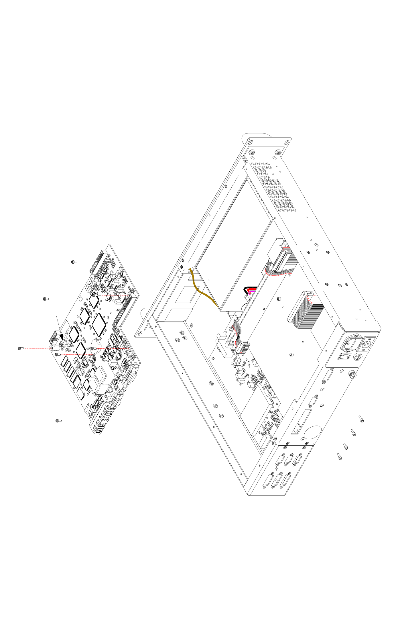
Fig 46 T6T VHF Drive Assembly Processor Module - Removal and Refitting Detail
CN6
CN5 CN1
CN4
CN3
CN12
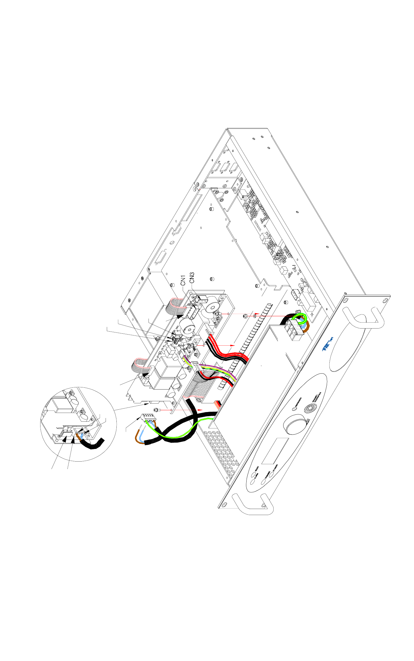
Fig 47 T6T VHF Drive Assembly PSU Regulation Module - Removal and Refitting Detail
Brown (L)
Blue (N)
CN2
CN7
CN6
CN8
CN9
CN8
CN5
CN4
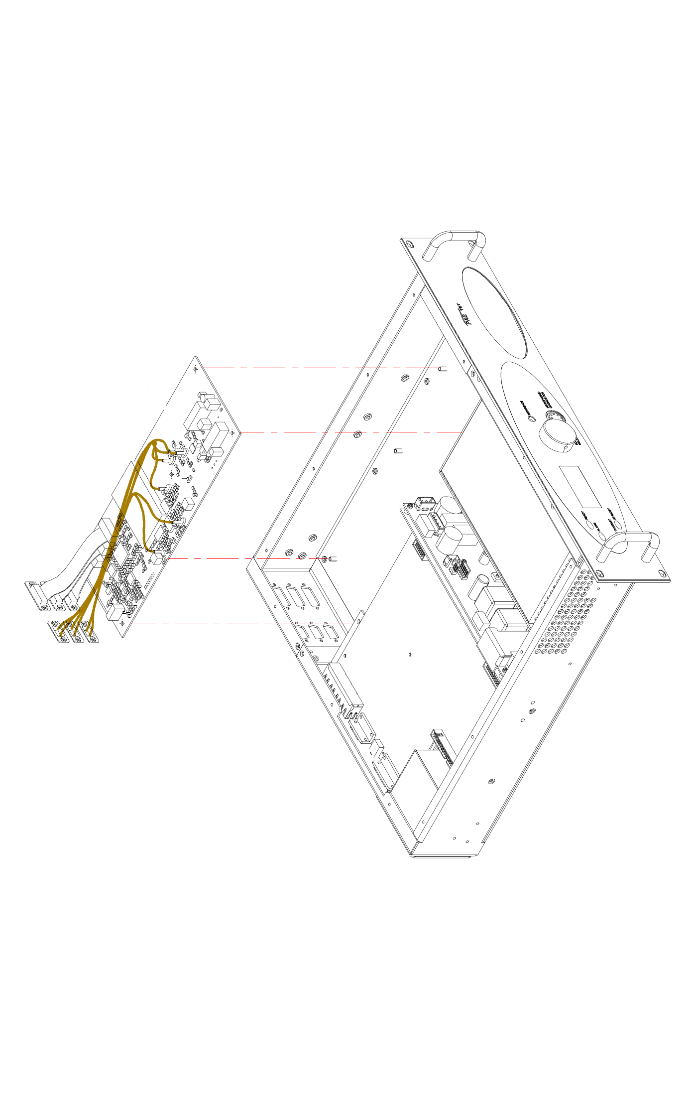
Fig 48 T6T VHF Drive Assembly Drive Module - Removal and Refitting Detail
Driver Module
CN10
CN9
CN7
CN8
CN11
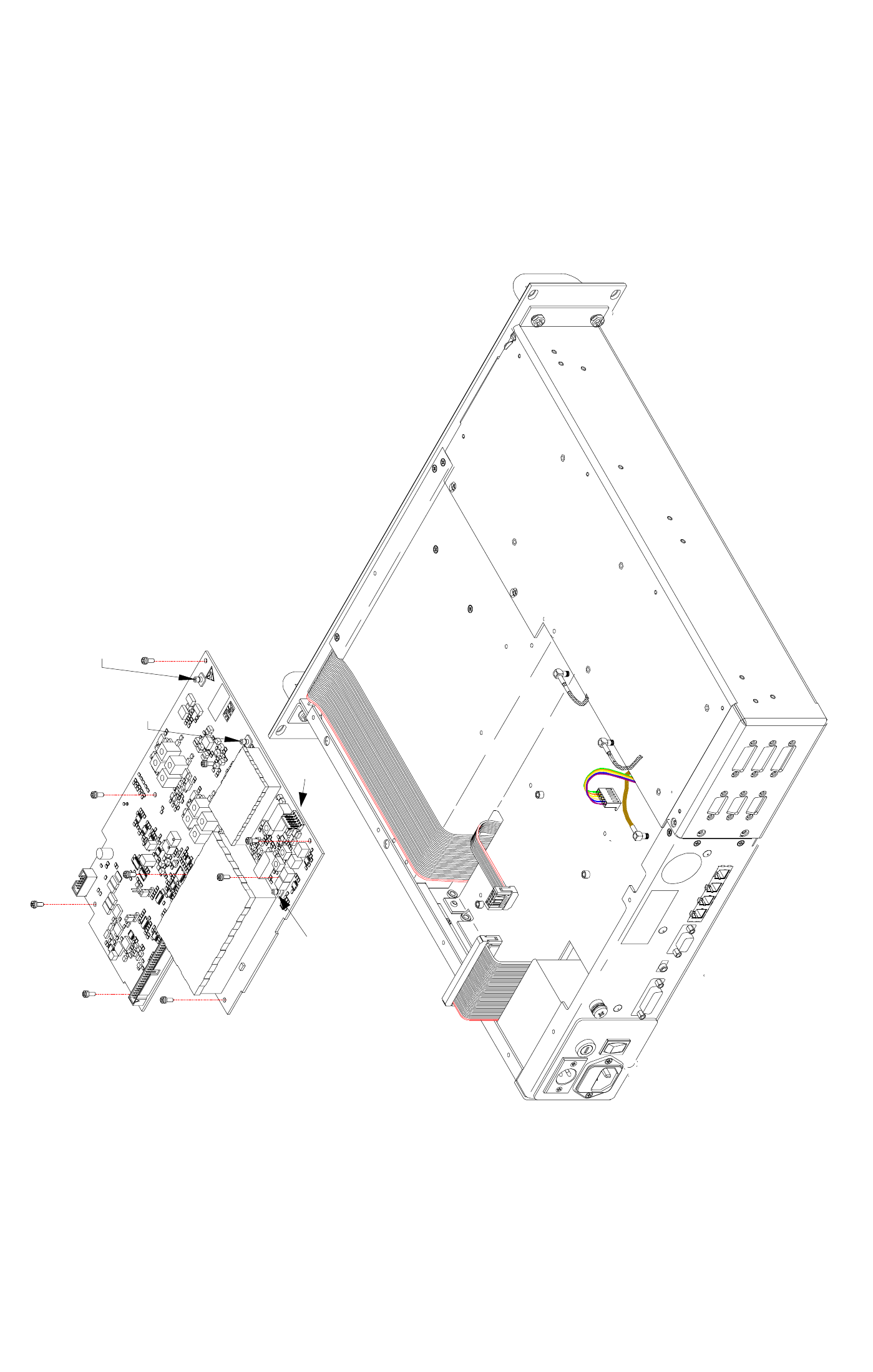
Fig 49 T6T VHF Drive Assembly PA Control Module - Removal and Refitting Detail
CN4
CN3
PC3
CN3
CN4
CN2
CN5
CN1
CN6
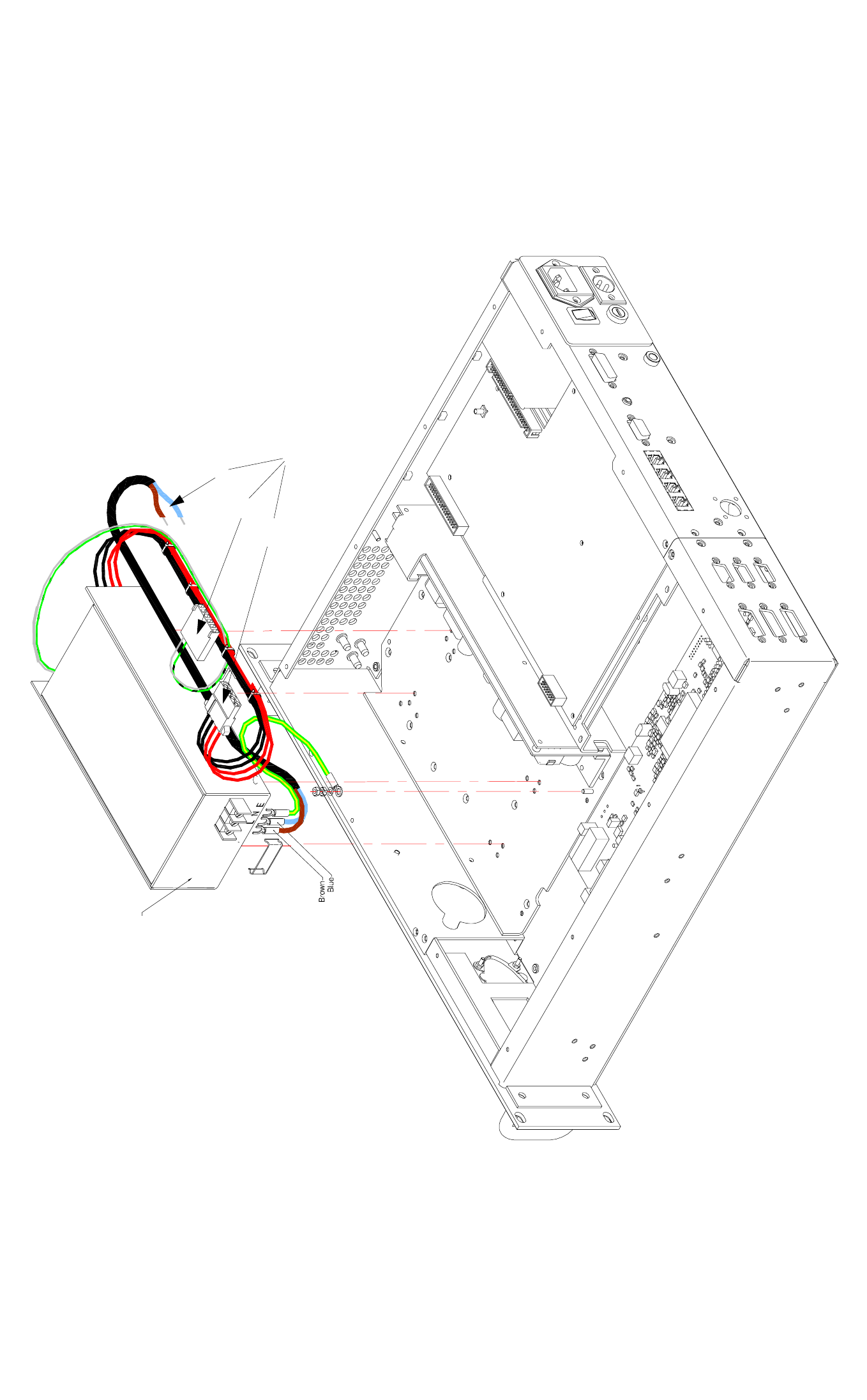
Fig 50 T6T VHF Drive Assembly Power Supply - Removal and Refitting Detail
Power Supply
CN1
CN6
CN9
To PSU Regulation
Module
Power Supply
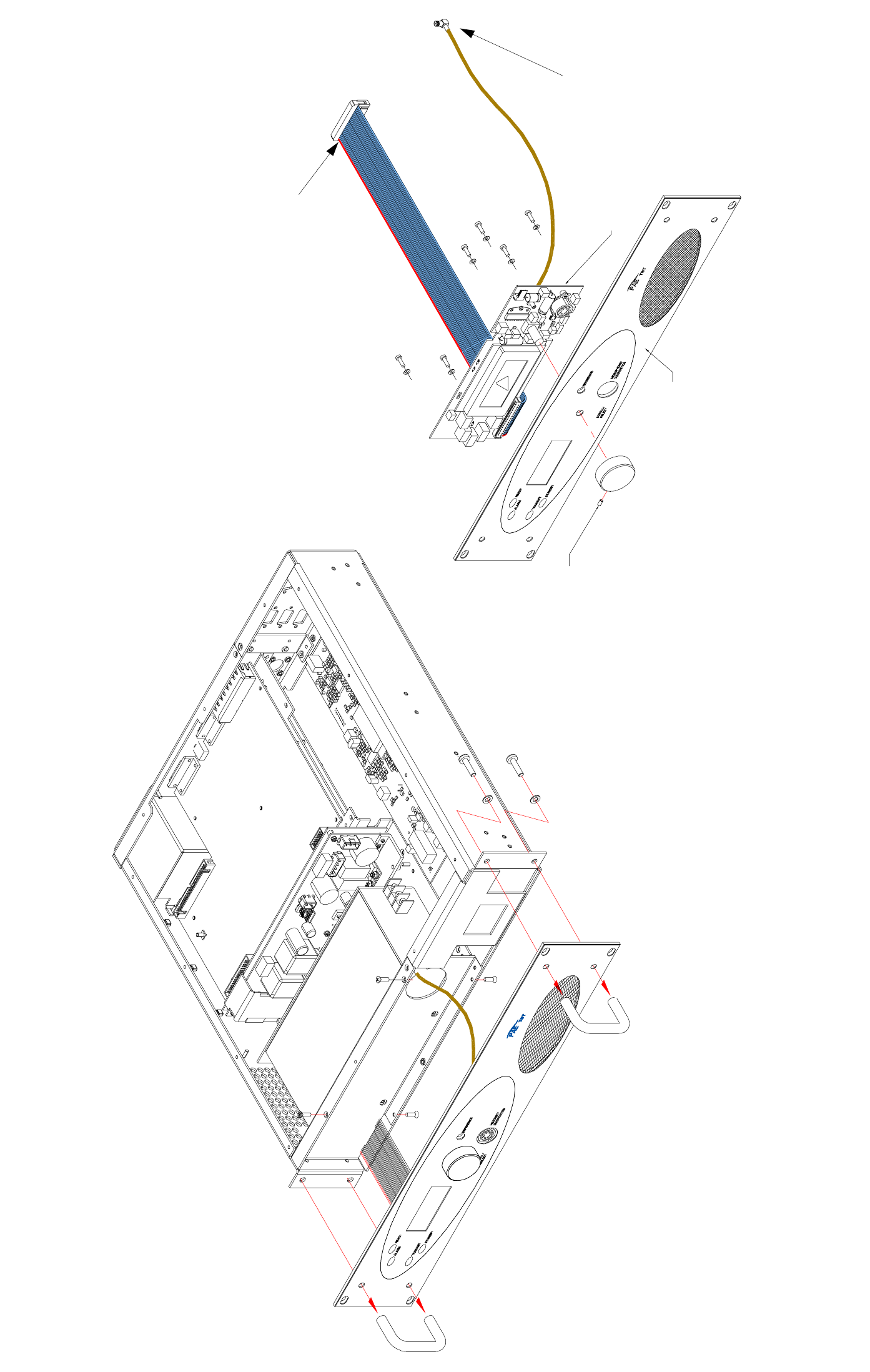
Fig 51 T6T VHF Drive Assembly Front Panel PCB - Removal and Refitting Detail
Front panel PCB
1
Allen head grub screw
To Processor module CN4
To PA Control module CN5
Front panel PCB
Front panel
Allen head grub screw
Diagram B
Diagram A