Park Air Systems B6350 50W VHF Ground to air transmitter User Manual T6T User Guide vp
Park Air Systems Limited 50W VHF Ground to air transmitter T6T User Guide vp
UserManual.wiki
>
Park Air Systems
>
B6350 User Manual
Exhibit D User guide
Navigation menu
Upload a User Manual
Namespaces
Wiki Guide
HTML
PDF
Info
Views
User Manual
Discussion / Help
Navigation
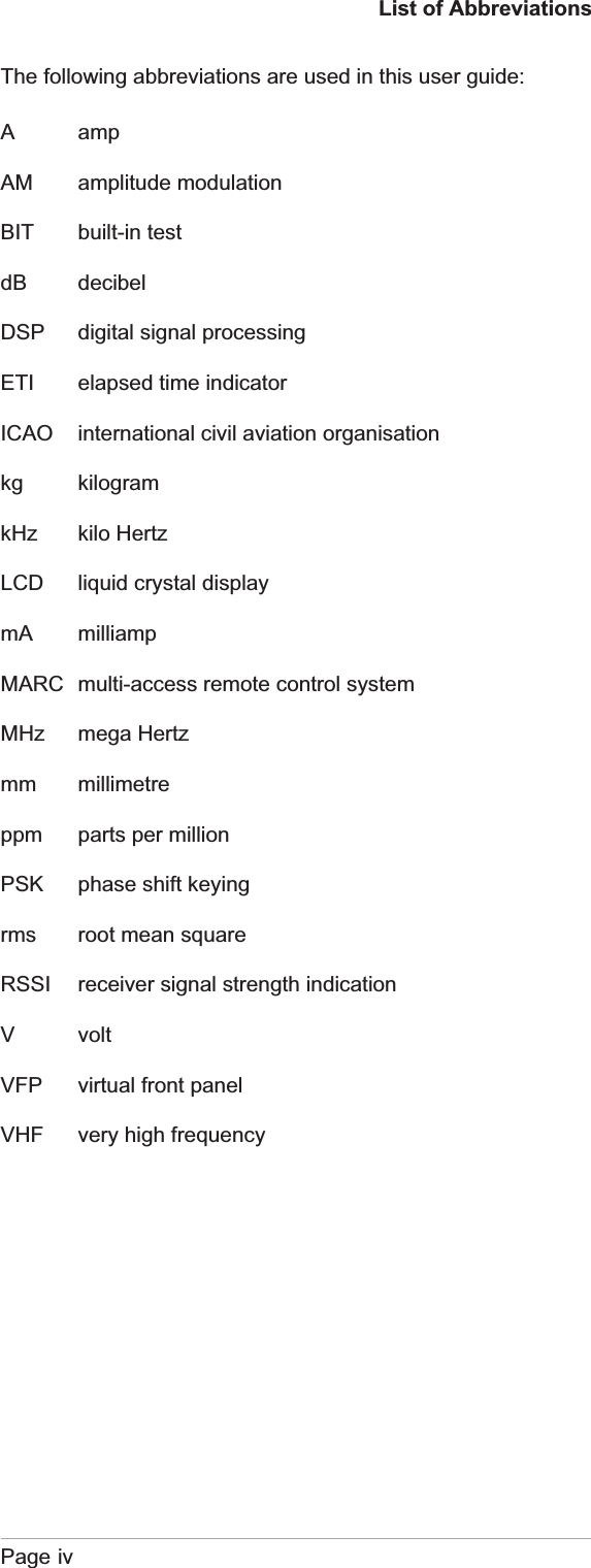

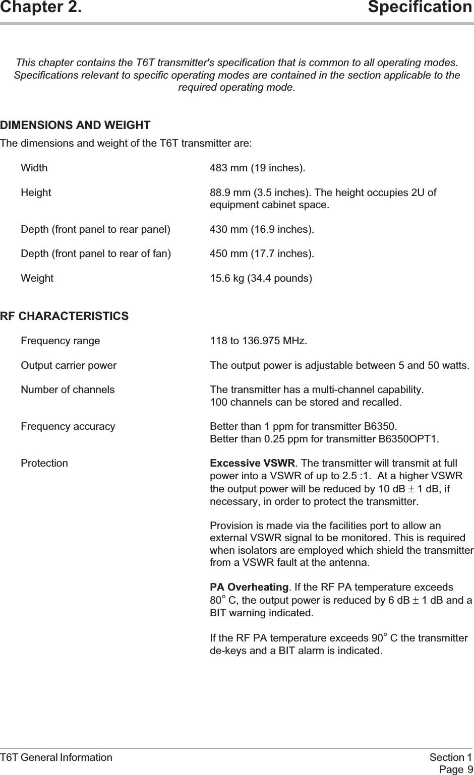
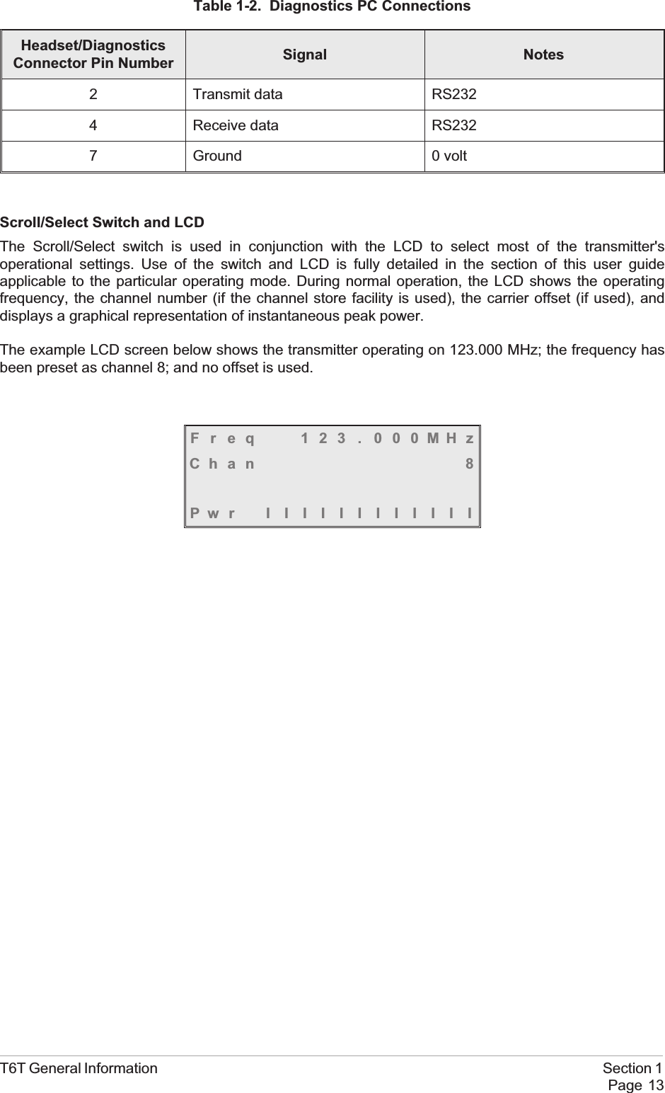
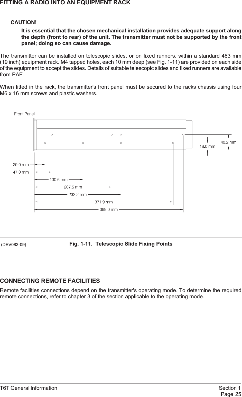

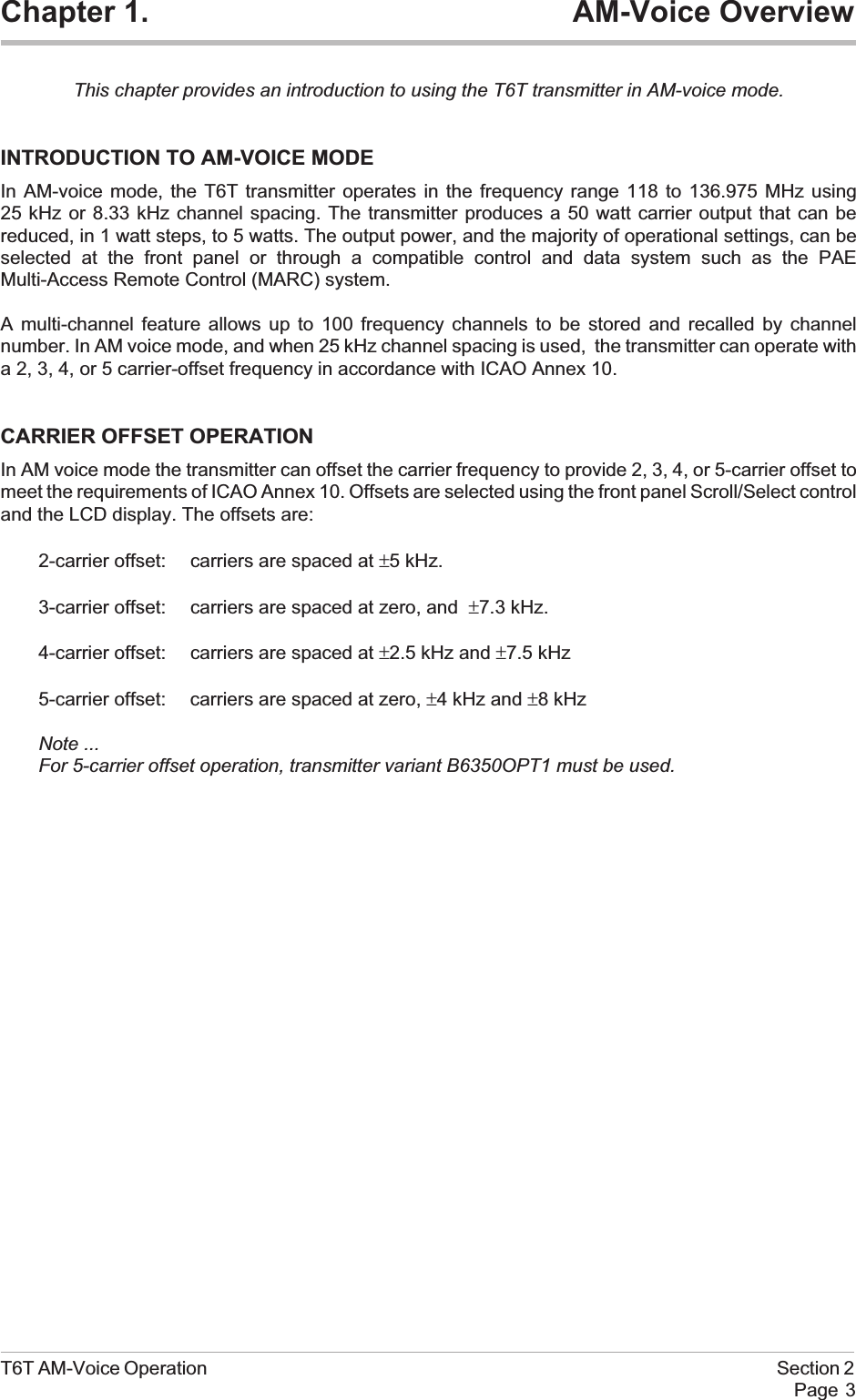
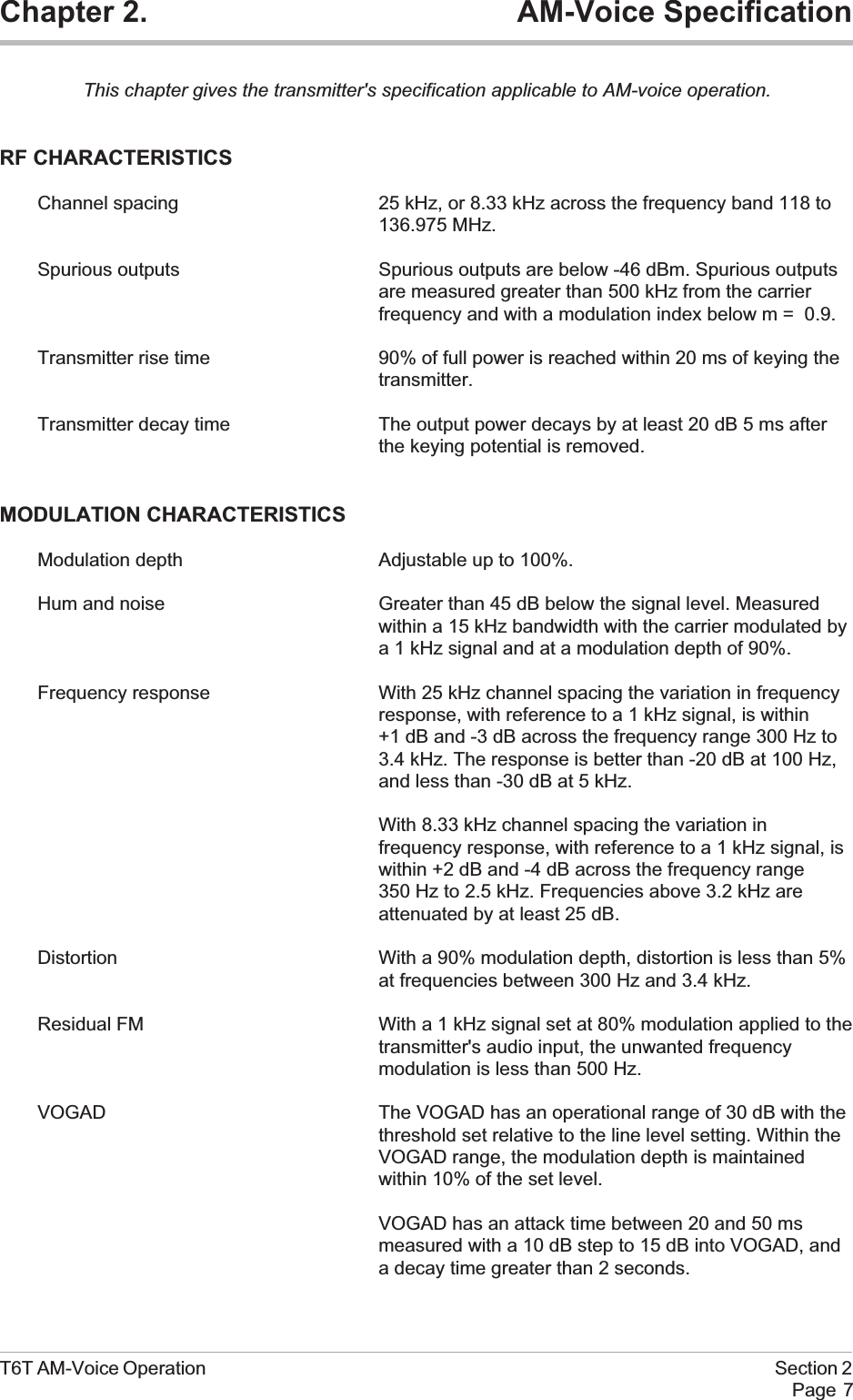

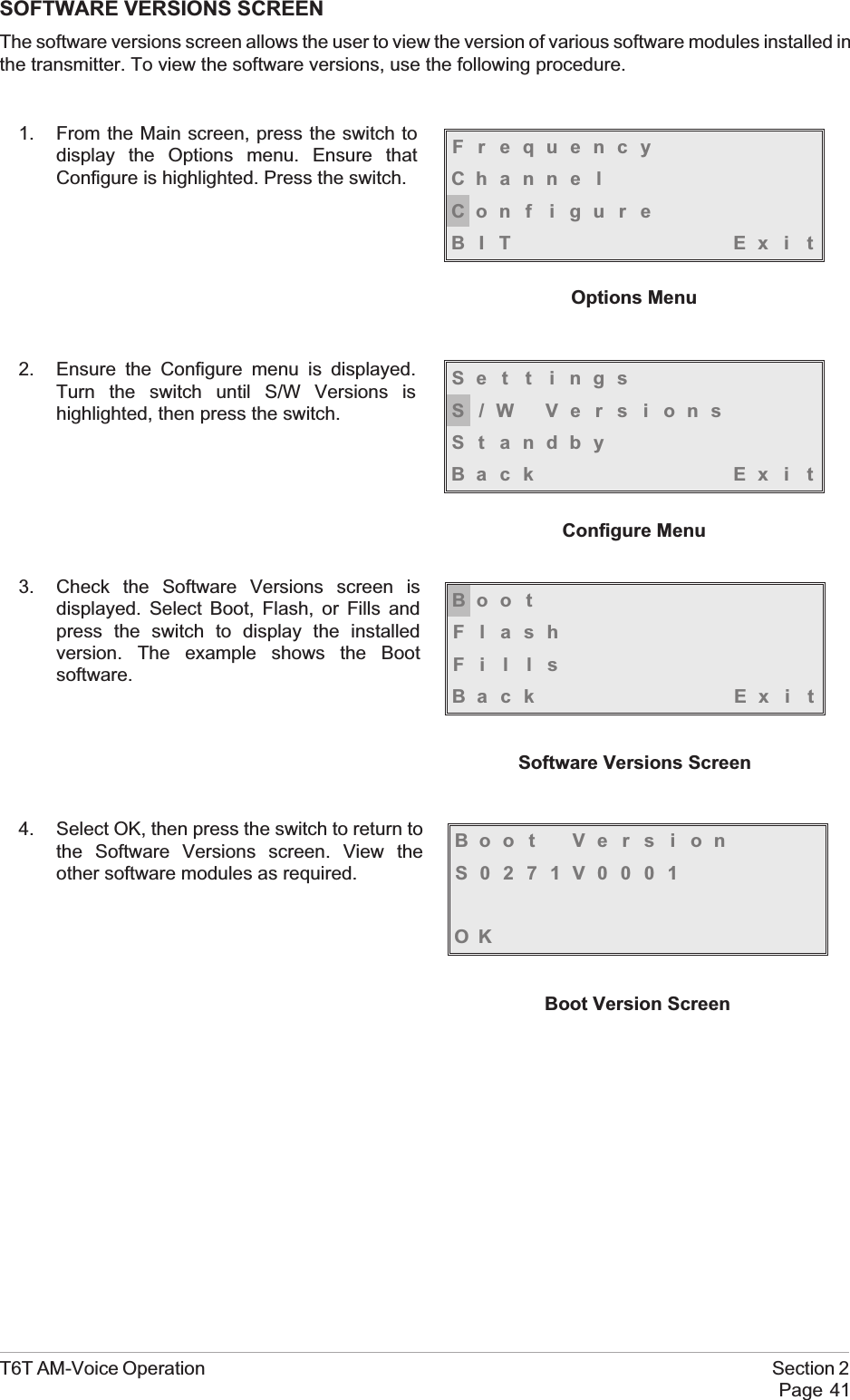
![REMOTE KEYING CONFIGURATIONSDuring installation jumpers JP8 and JP9 must be set to suit the remote keying potential. The keyingpotentials are 0 volt, a dc voltage between +10 and +50 V, or a dc voltage between -10 and -50 V.The following illustrations show the PTT signal, the settings of jumpers JP8 and JP9, and the ‘PTT inpolarity’ that must be set at the front panel when completing the ‘Operational Settings’ procedures.T6T AM-Voice Operation Section 2Page 11Phantom KeyingRemote Keying28V0VJP8 JP9T6T Transmitter[Front panel PTT Polarity = POS]PTT Switch0 voltRemote PTT0 Volt Keying[Factory default setting]+10 to +50 Volt Keying with Positive Going Active SignalPhantom KeyingRemote Keying28V0VJP8 JP9T6T Transmitter[Front panel PTT Polarity = POS]+10 to +50 V0VPTTPhantom KeyingRemote Keying28V0VJP8 JP9T6T Transmitter[Front panel PTT Polarity = NEG]PTT+10 to +50 V0V+10 to +50 Volt Keying with Negative Going Active Signal](https://usermanual.wiki/Park-Air-Systems/B6350/User-Guide-92368-Page-43.png)
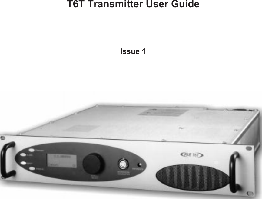
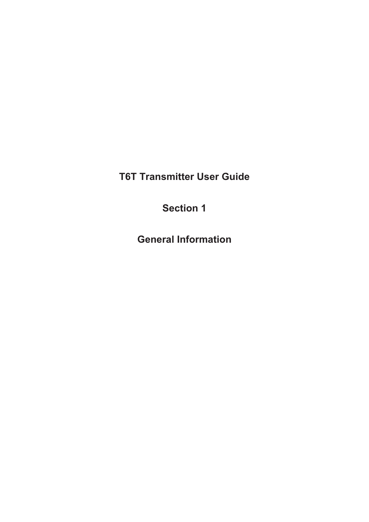
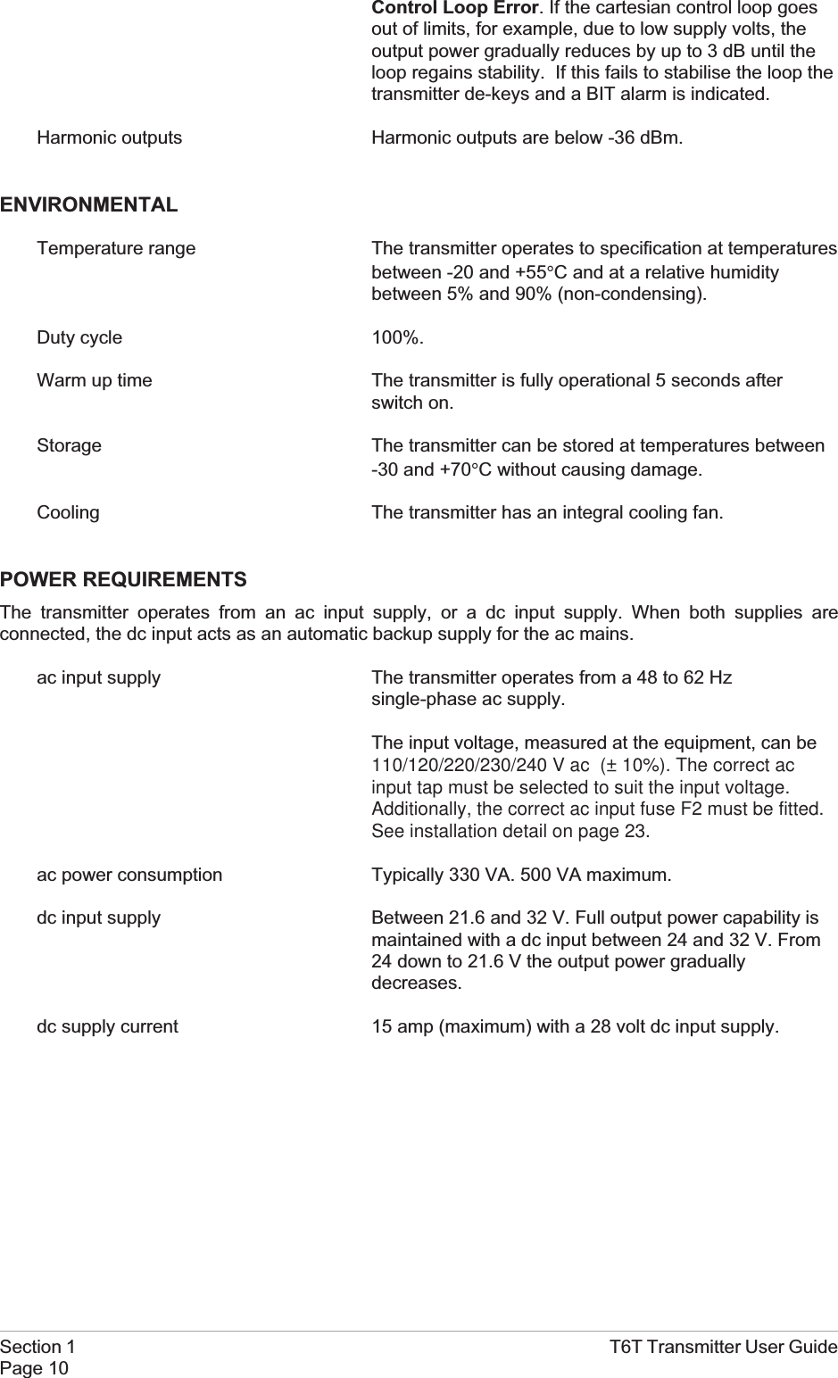
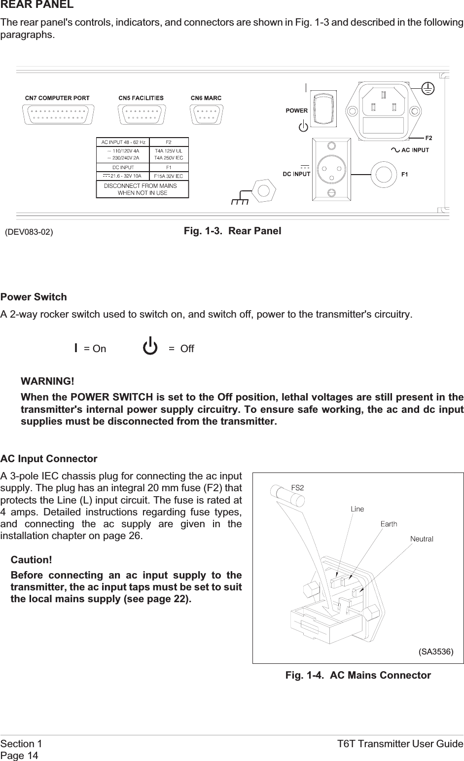
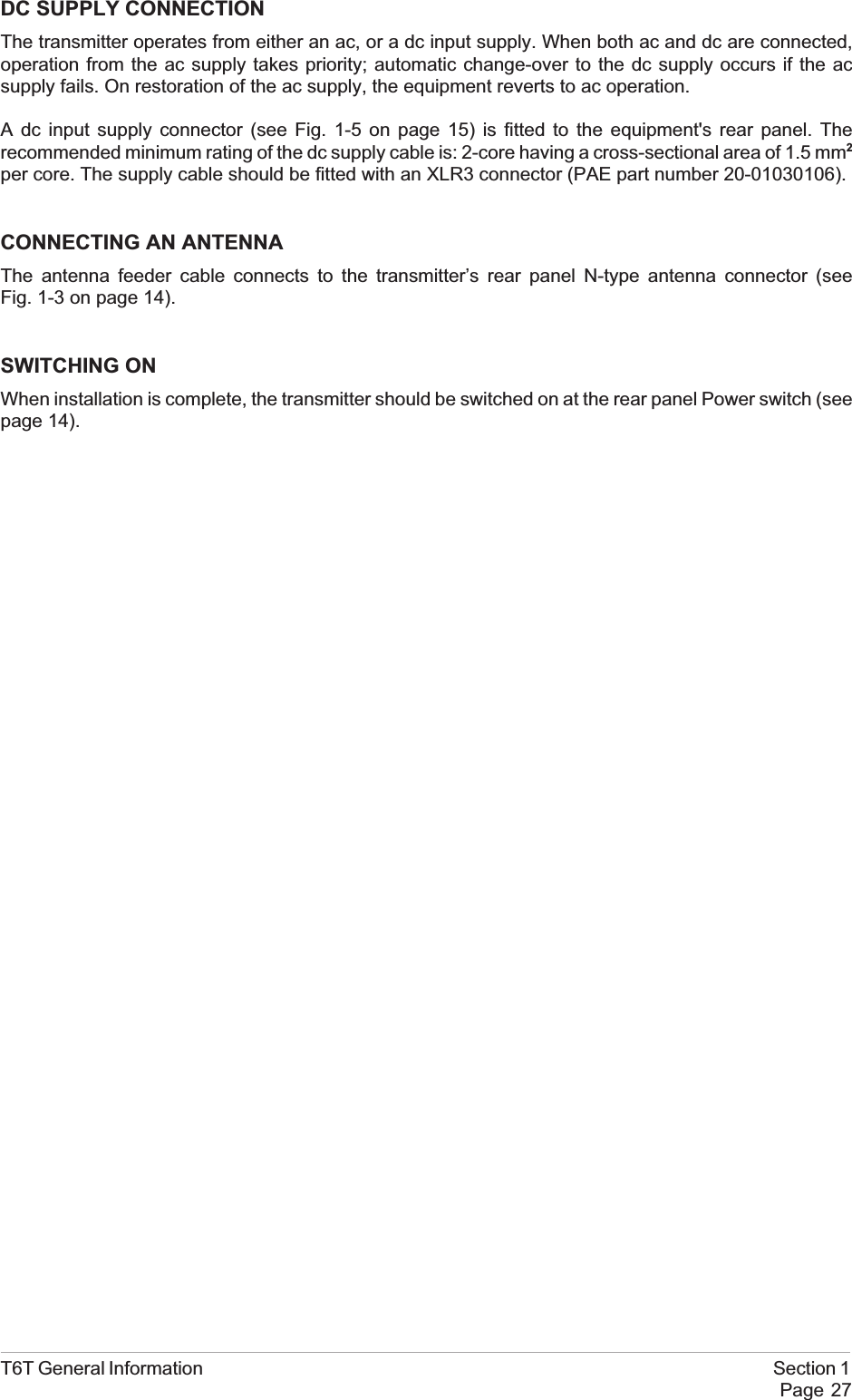
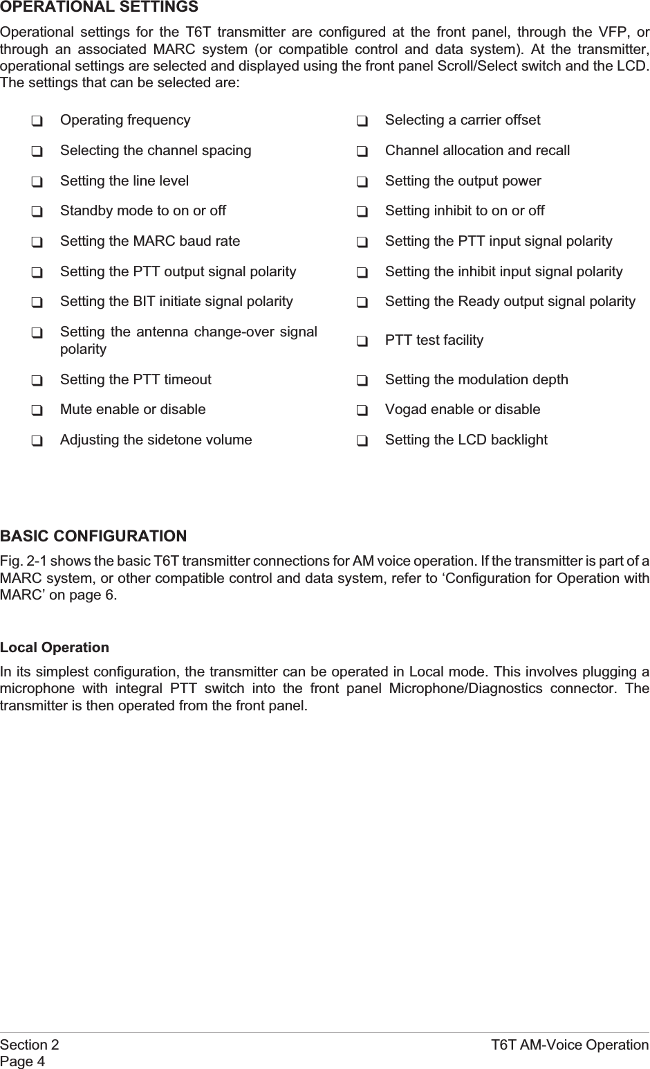
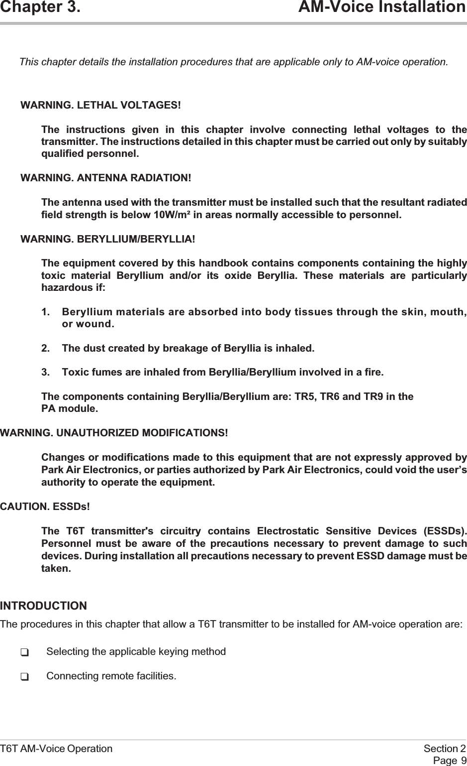
![PHANTOM KEYING CONFIGURATIONSPhantom keying can be used with the transmitter. This involves superimposing a dc potential on theaudio lines at the control equipment. The potential can be 0 volt, or between 10 and 50 volts as shown inthe illustrations on the opposite page.To use phantom keying, the PTT switch at the control equipment must connect to a centre-tap on the600 ohm audio transformer. The keying potential is connected to the centre-tap.At the transmitter, jumpers JP8 and JP9, fitted to the DSP module, must be correctly set for phantomkeying.Note that the audio lines in the illustrations connect to the transmitter's Facilities connector CN5. Ifphantom keying is required when using a MARC, or compatible control and data system, the linesconnect to the MARC connector CN6 pins 2 and 3.Section 2 T6T AM-Voice OperationPage 12Phantom KeyingRemote Keying28V0VJP8 JP9T6T Transmitter[Front panel PTT Polarity = POS]0V-10 to -50 VPTTPhantom KeyingRemote Keying28V0VJP8 JP9T6T Transmitter[Front panel PTT Polarity = NEG]PTT0V-10 to -50 V-10 to -50 Volt Keying with Negative Going Active Signal-10 to -50 Volt Keying with Positive Going Active Signal](https://usermanual.wiki/Park-Air-Systems/B6350/User-Guide-92368-Page-44.png)
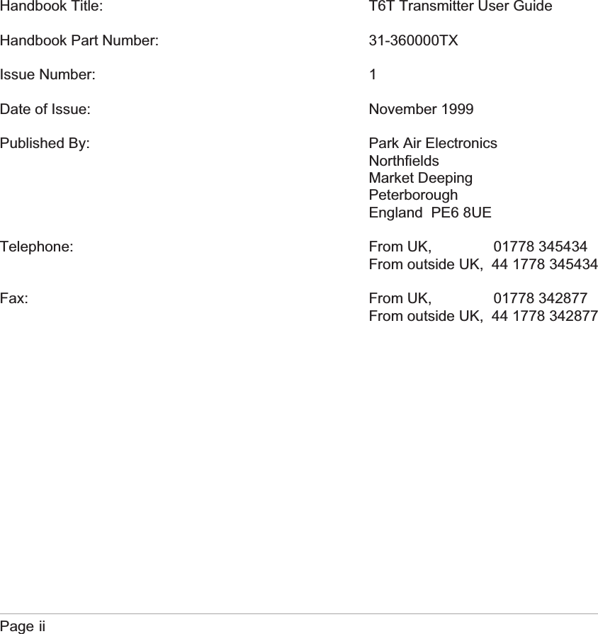
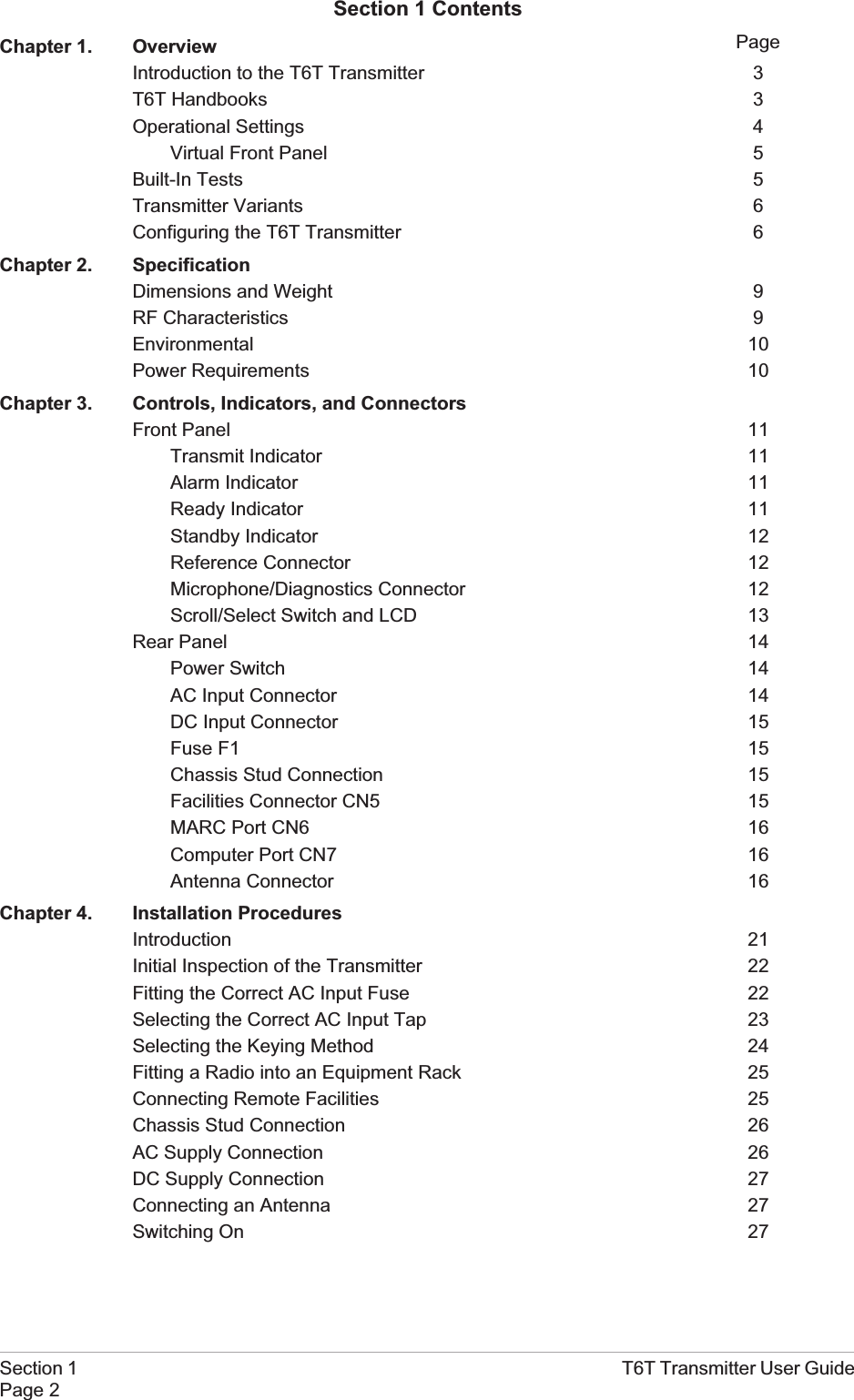
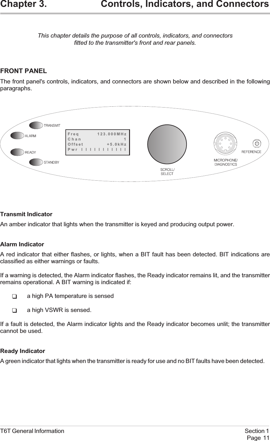
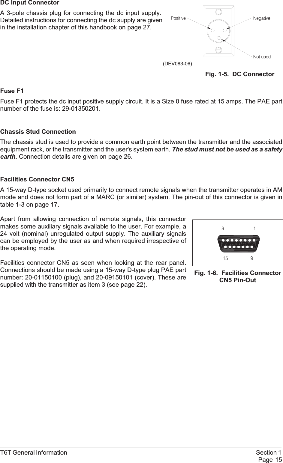
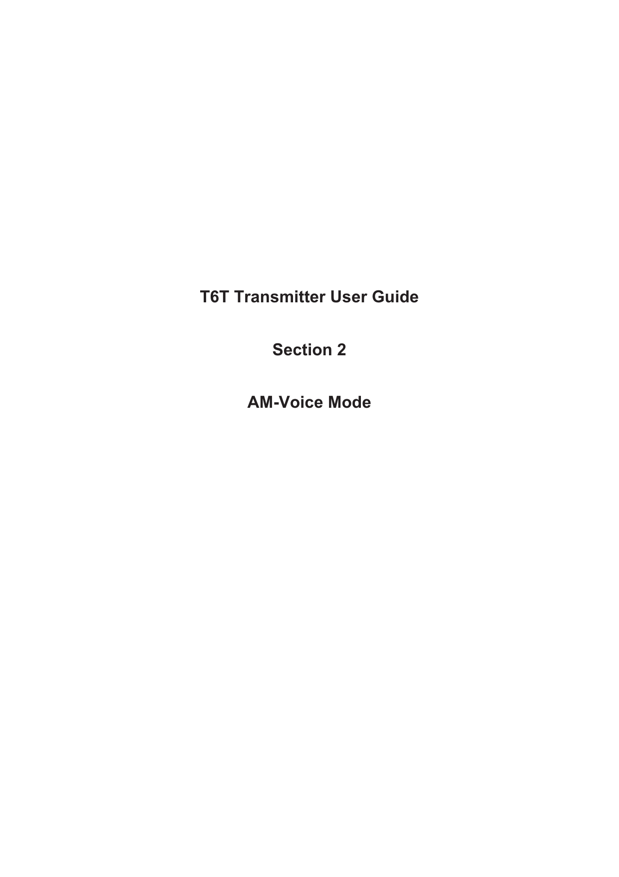
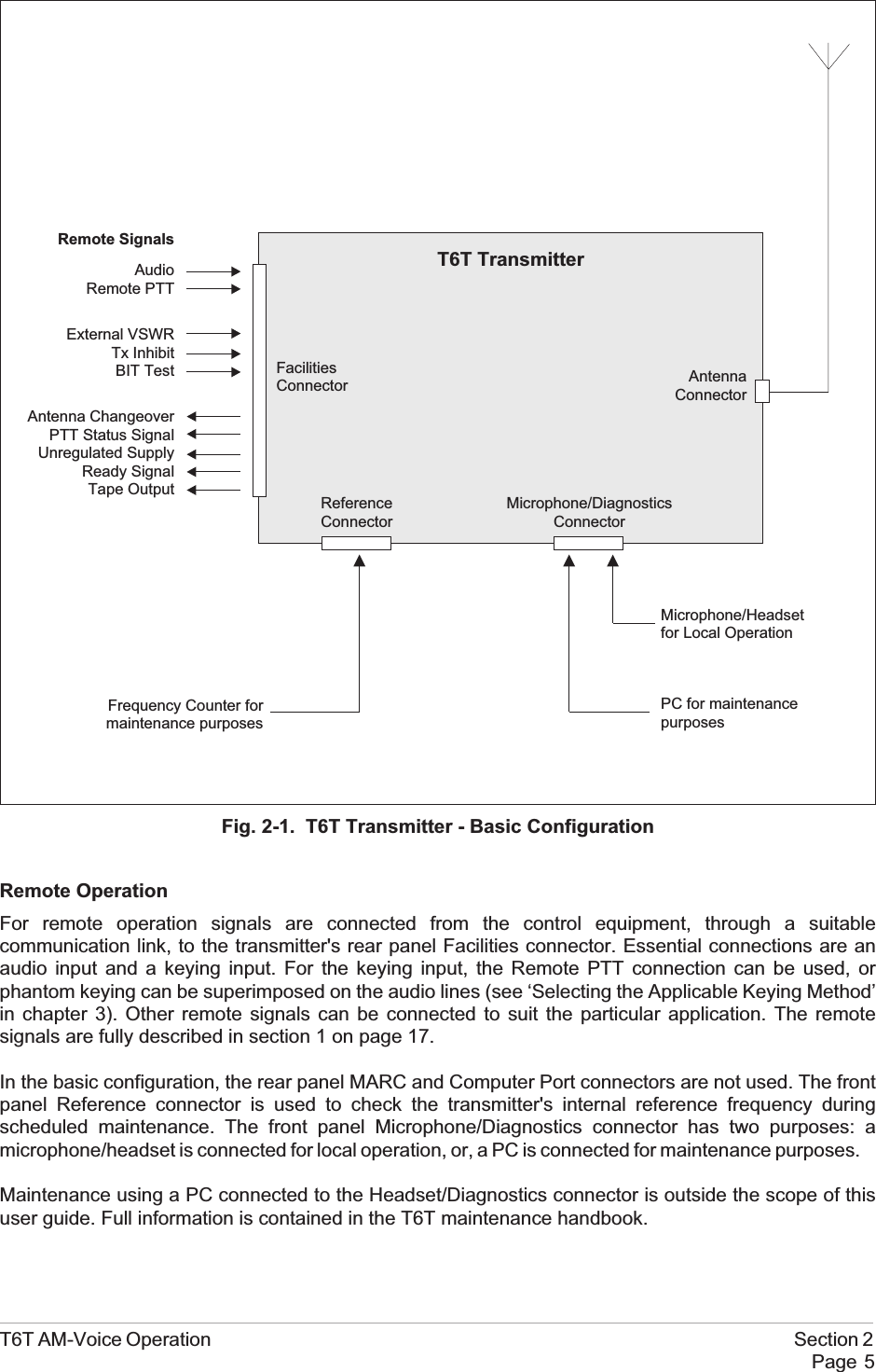
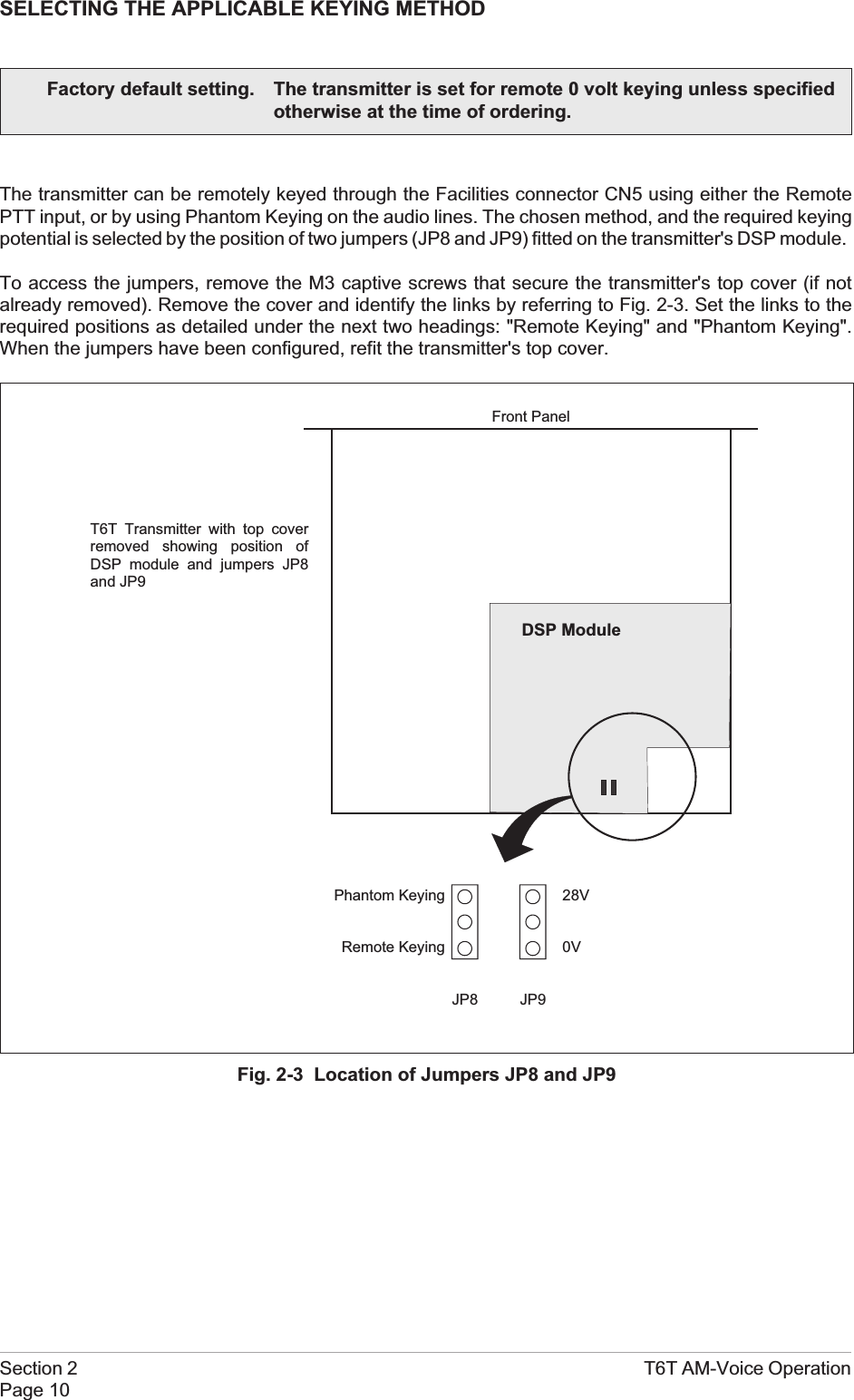
![T6T AM-Voice Operation Section 2Page 13Fig. 2-4. Phantom Keying ArrangementsPhantom KeyingRemote Keying28V0VJP8 JP9Phantom KeyingRemote Keying28V0VJP8 JP9[Front panel PTT Polarity = POS][Front panel PTT Polarity = POS]](https://usermanual.wiki/Park-Air-Systems/B6350/User-Guide-92368-Page-45.png)
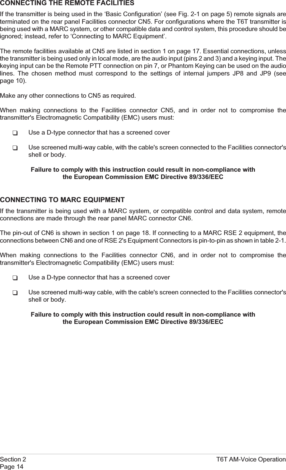
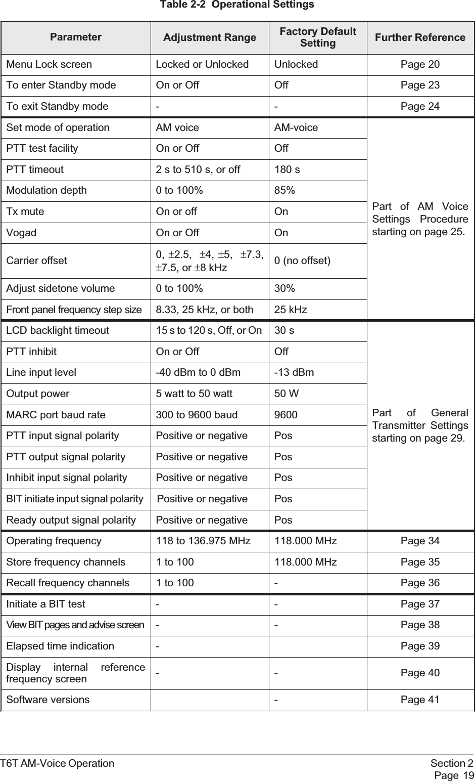
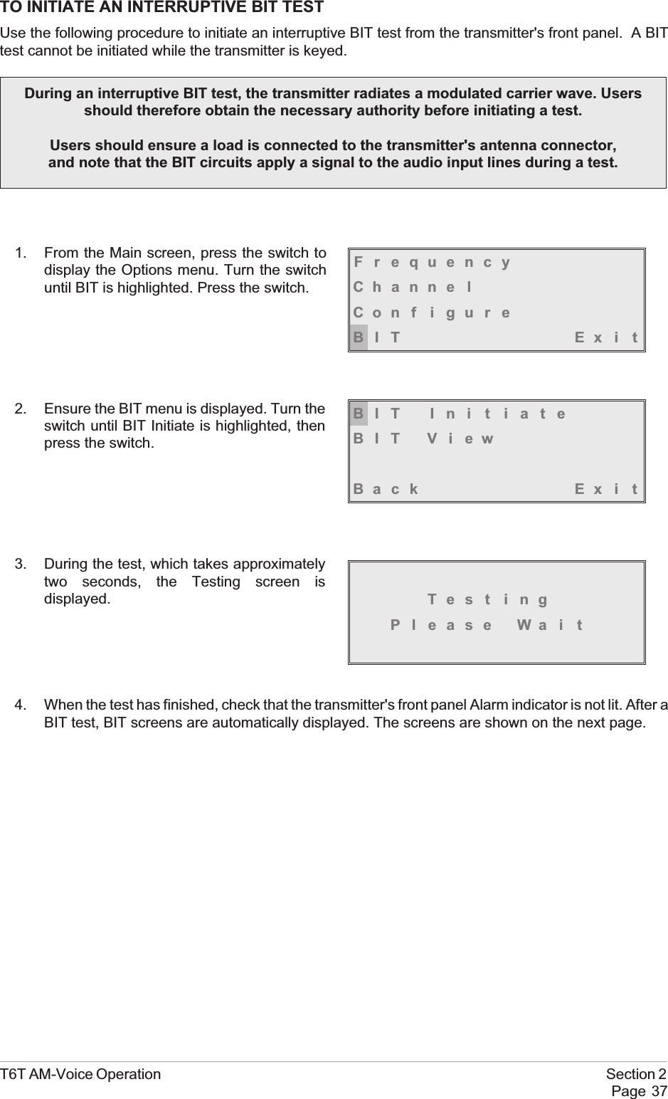
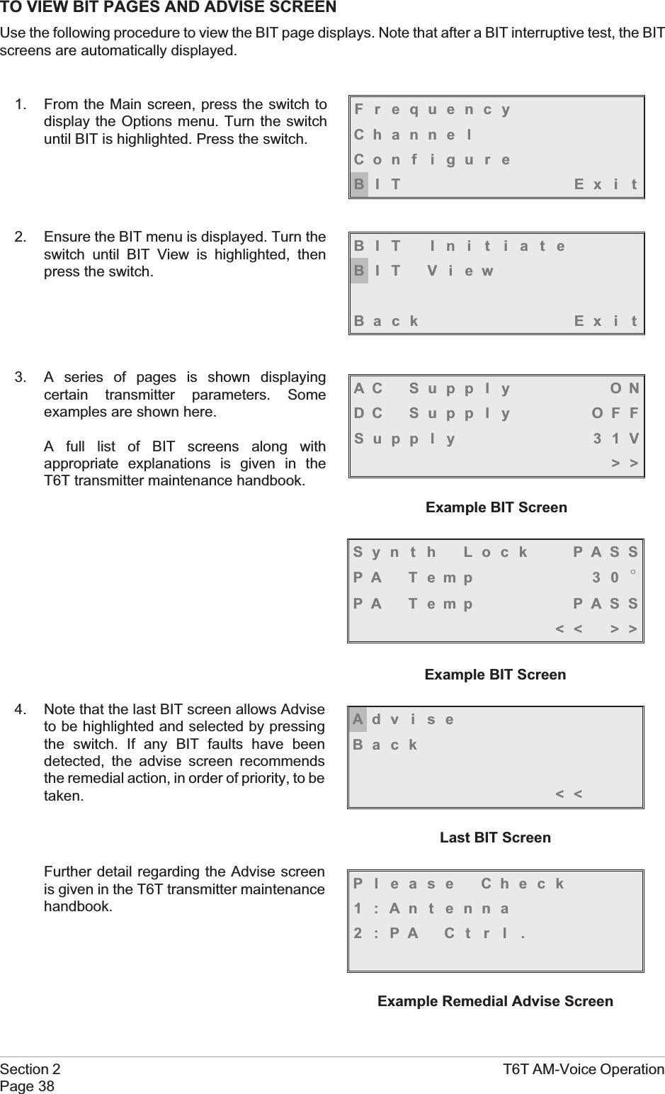
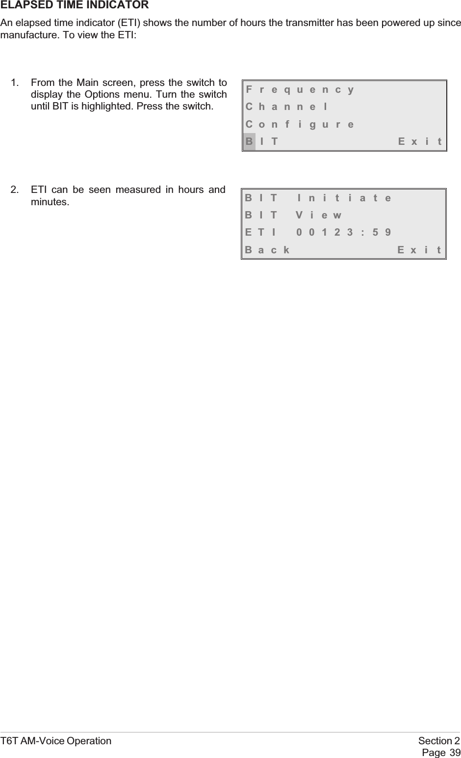
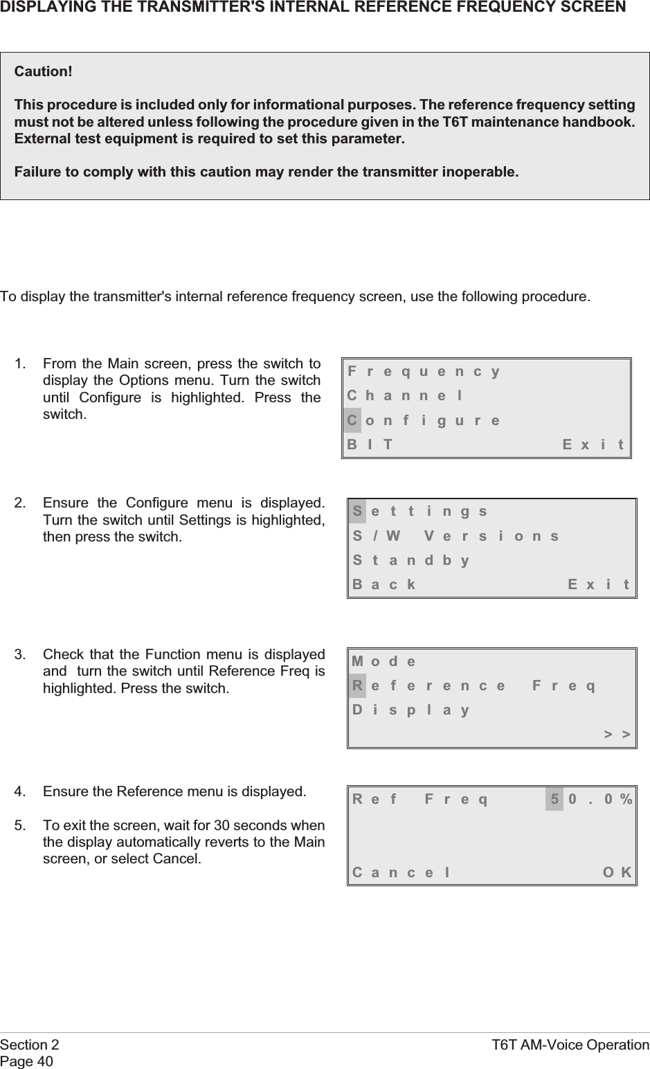
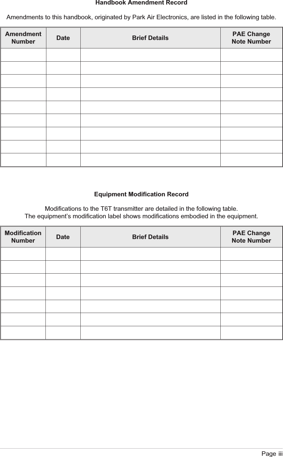
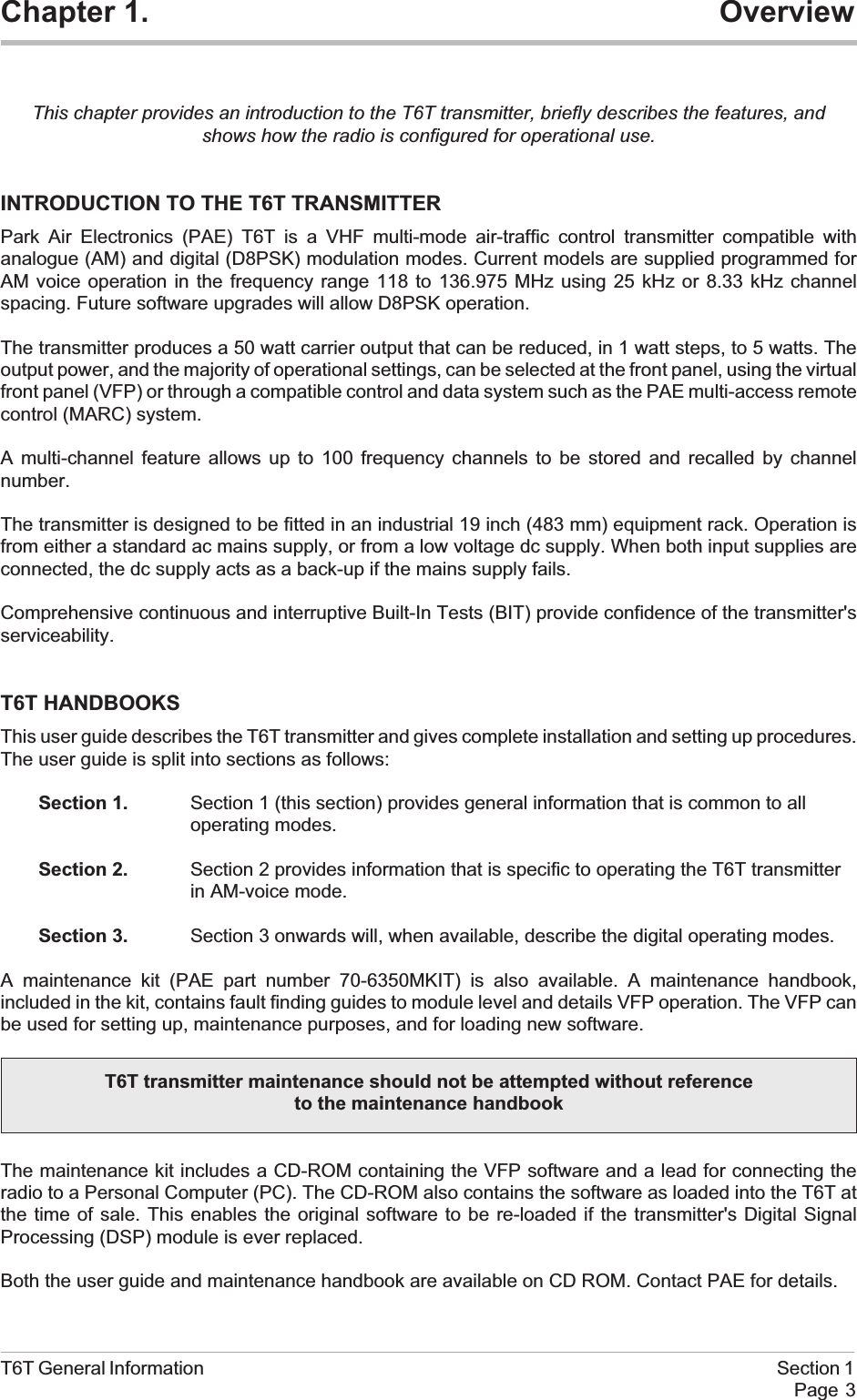
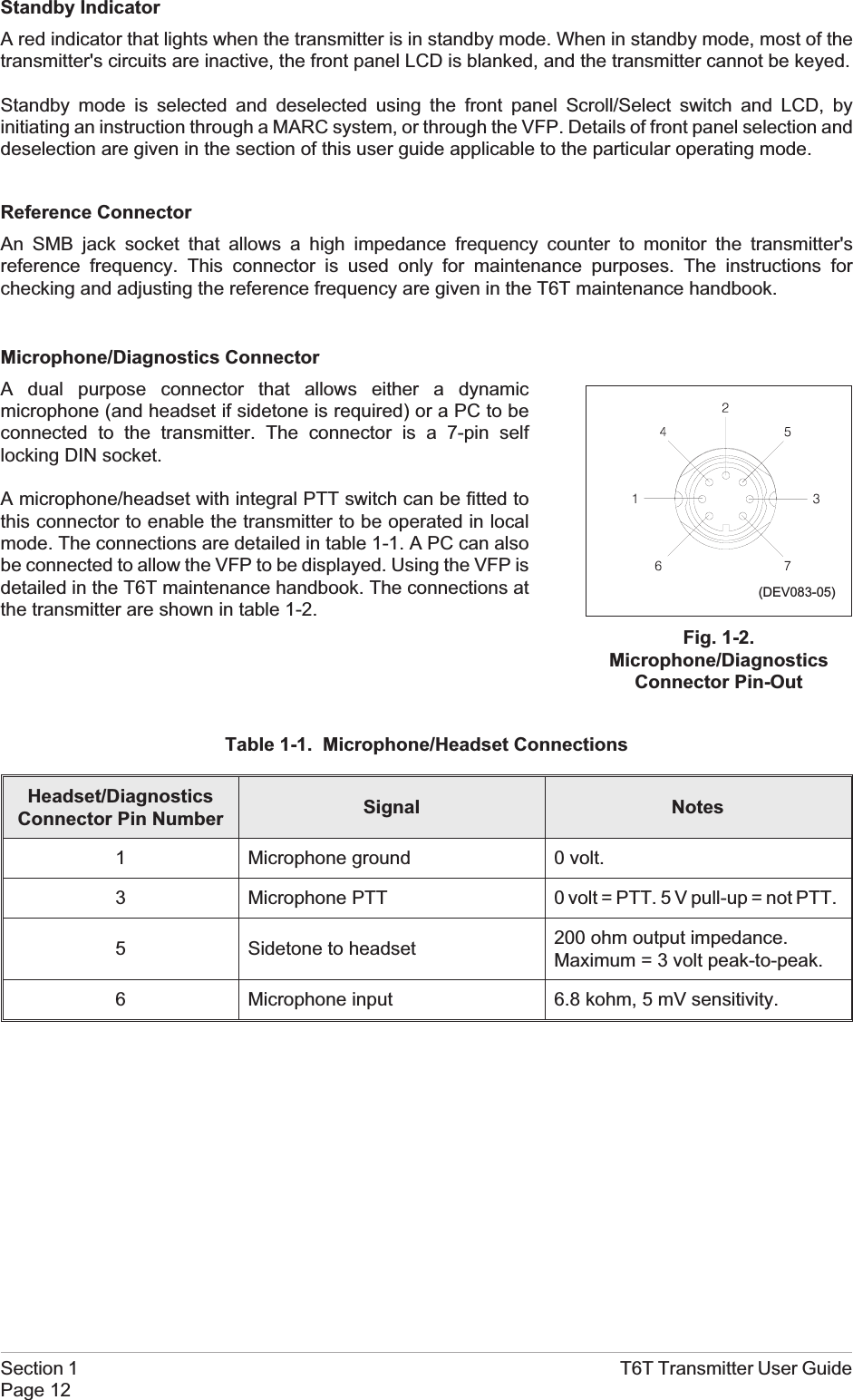
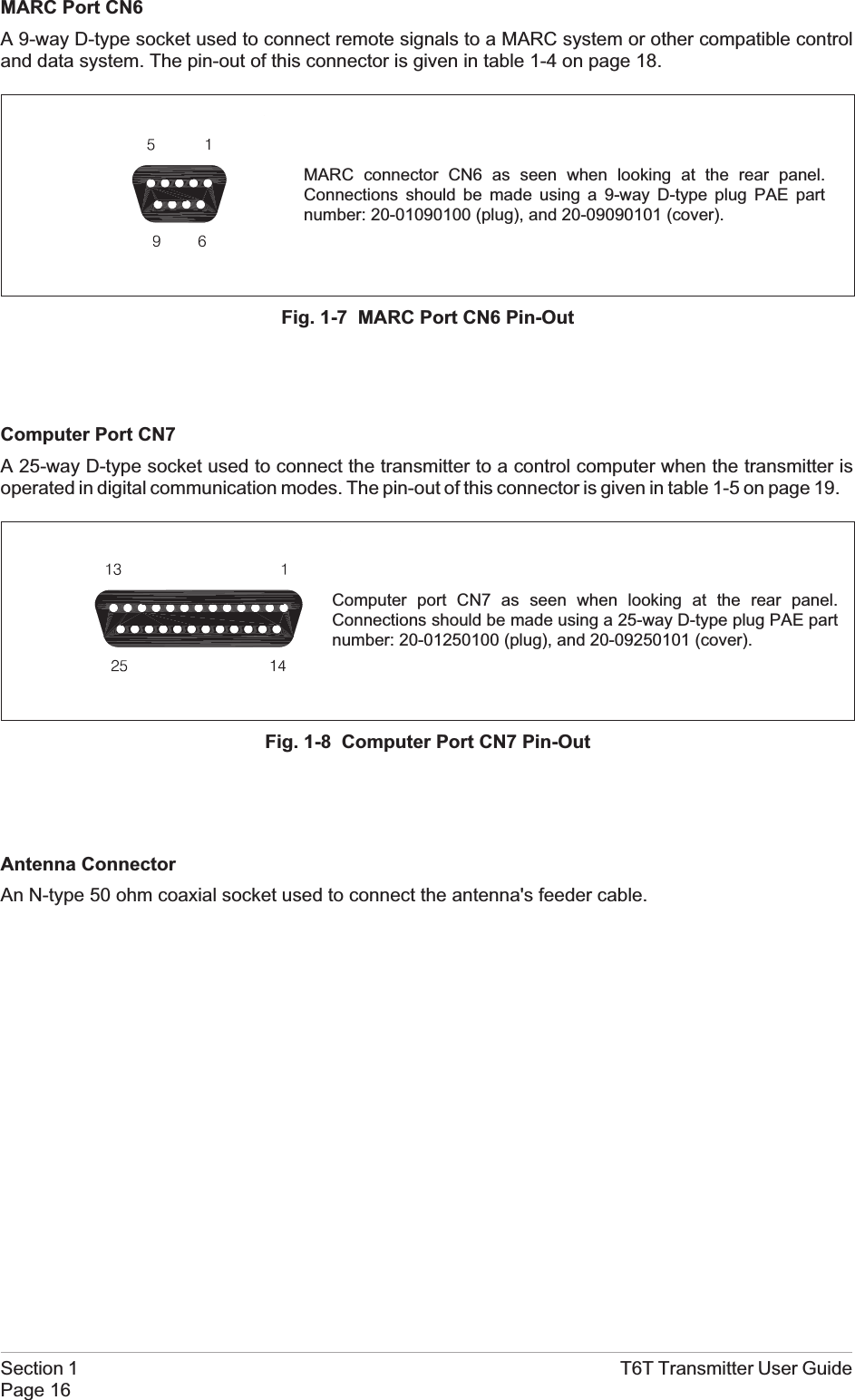
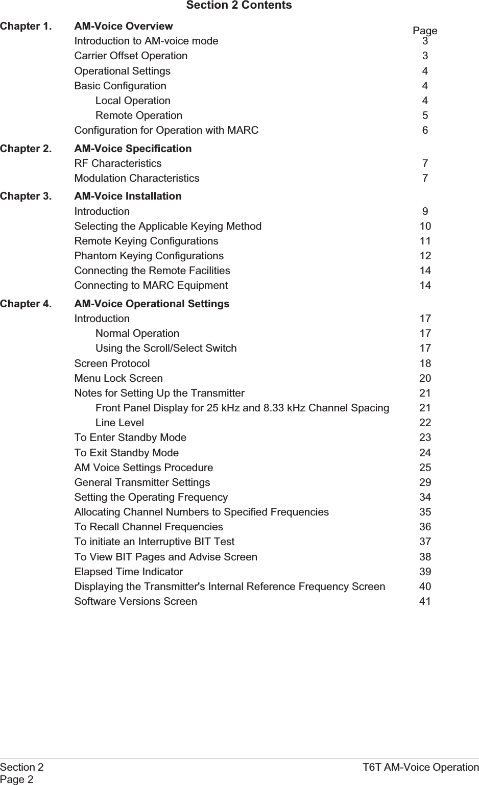
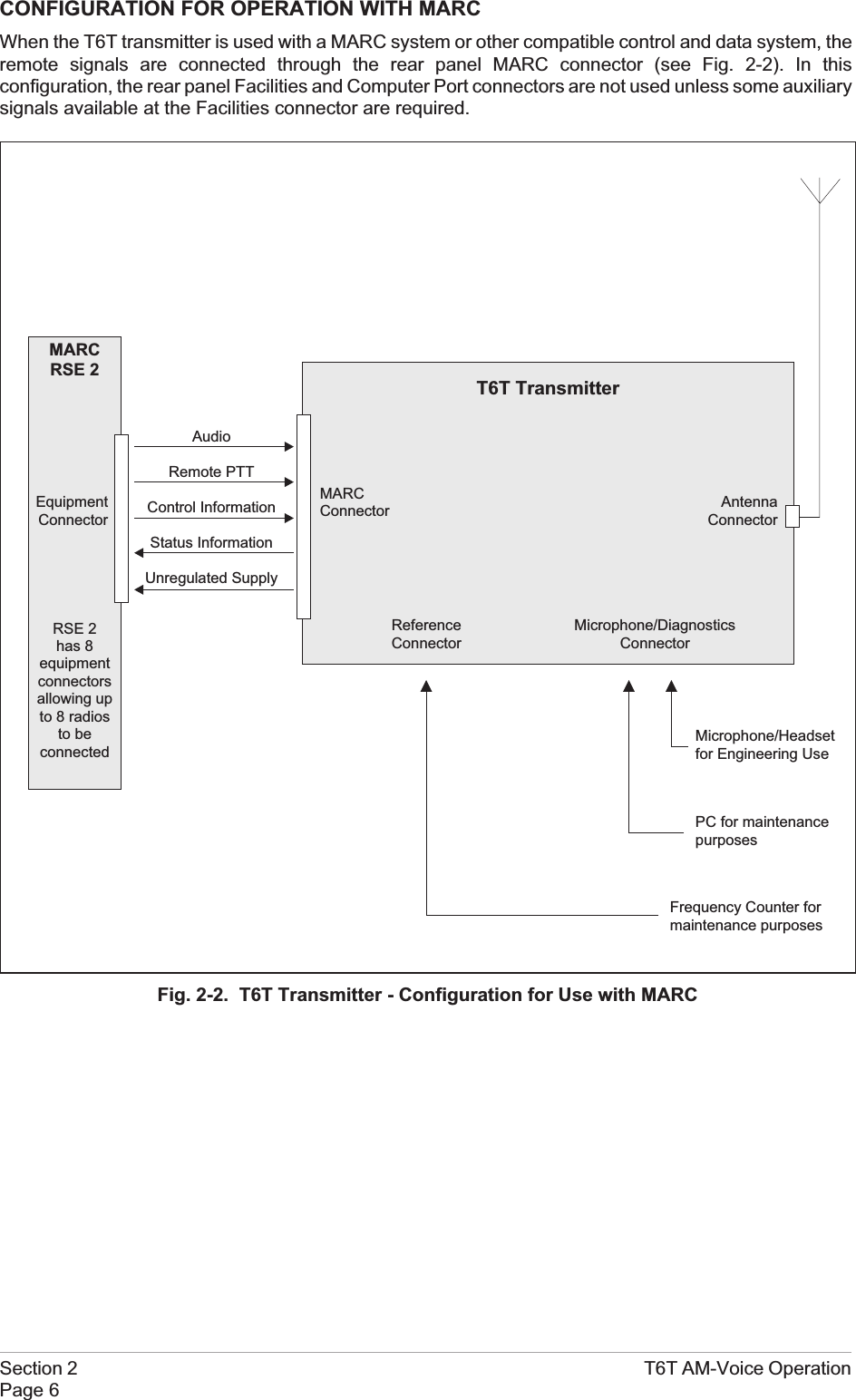
![TO ENTER STANDBY MODEStandby mode is a power saving feature that can be used for non-operational transmitters. When instandby mode, most of the transmitter's circuits are inactive, the LCD is blanked, and the transmittercannot be keyed. To put the transmitter into standby mode, use the following procedure.1. From the Main screen, press the switch todisplay the Options menu. Ensure thatConfigure is highlighted. Press the switch.2. Ensure the Configure menu is displayed.Turn the switch until Standby is highlighted,then press the switch.3. Check that the Standby menu is displayed.Turn the switch until Yes is highlighted, thenpress the switch. [To abandon thisprocedure, select No instead of Yes andthen press the switch.]4. Check that the LCD blanks, and the front panel STANDBY indicator lights.5. The transmitter is now in standby mode. To exit standby, see the next procedure.T6T AM-Voice Operation Section 2Page 23FrequencyChanne lCon f i gu r eBIT Exi tSe t t i ngsS/W VersionsSt andbyBack Ex i tPut radio intoSt andby mode ?YES NO](https://usermanual.wiki/Park-Air-Systems/B6350/User-Guide-92368-Page-55.png)
![TO EXIT STANDBY MODEStandby mode is indicated by the front panel STANDBY indicator being lit and the LCD being blanked.To exit this mode, use the following procedure.1. Press the switch and check that the Exitmenu is displayed.2. Turn the switch until YES is highlighted, then press the switch. [To abandon this procedure,select No instead of Yes and then press the switch.]3. Check that the transmitter's Main screen isdisplayed and that the front panelSTANDBY indicator is unlit.4. The transmitter is now ready for normal use.Section 2 T6T AM-Voice OperationPage 24Ex i t S t andbyMod eYES NOFreq 123 . 000 MHzPw r](https://usermanual.wiki/Park-Air-Systems/B6350/User-Guide-92368-Page-56.png)
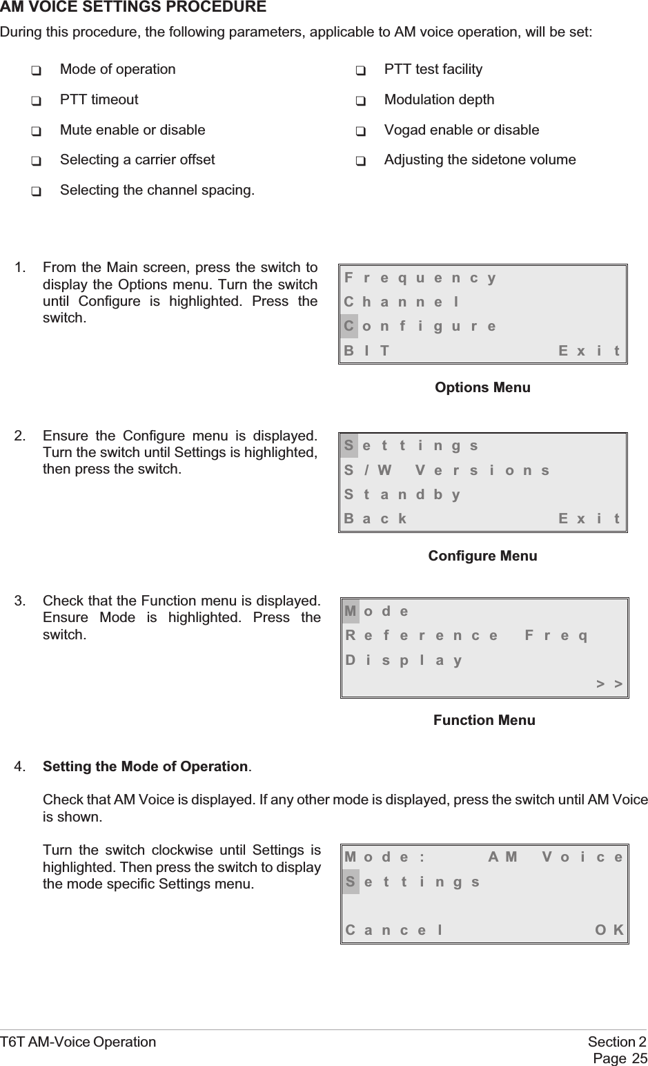
![5. Setting the PTT Test Facility.[Factory default setting: Off]The PTT test facility can be set to Off or On.When Off is selected, the transmitter is keyed only when the PTT signal is active.When On is selected, the transmitter keys, and remains keyed until the display times out.To set the PTT facility, ensure PTT ishighlighted. Press the switch to togglebetween Off and On. When the requiredsetting is displayed, turn the switch clockwiseto highlight PTT Timeout.6. Setting the PTT Timeout.[Factory default setting: 180 s]The PTT timeout can be set to a value between 2 and 510 seconds (in two second steps), or it canbe set to Off. This setting affects the transmitter when keyed by a front panel microphone, orthrough the remote lines.To set the timeout ensure that PTT Timeout ishighlighted and press the switch. Turn theswitch clockwise to increment the time inseconds, or anti-clockwise to decrement thetime in seconds. Note that the fullyanti-clockwise position switches the PTTtimeout to Off. When the required time, or Off,is displayed press the switch. Turn the switchclockwise to highlight Mod Depth.7. Setting the Modulation Depth.[Factory default setting: 85%]The transmitter's modulation depth can be setbetween 0 and 100% in increments of 1%.To set the required value, ensure that ModDepth is highlighted and press the switch.Turn the switch clockwise or anti-clockwise toincrement or decrement the value. When therequired value is displayed, press the switch.Turn the switch clockwise until the next screenis displayed and Mute is highlighted.Section 2 T6T AM-Voice OperationPage 26PTT OFFPTT T imeout 30sMod Depth 90%>>Mode Specific Settings MenuPTT OFFPTT T imeout 30sMod Depth 90%>>PTT OFFPTT T imeout 30sMod Depth 90%>>](https://usermanual.wiki/Park-Air-Systems/B6350/User-Guide-92368-Page-58.png)
![8. Setting Mute On or Off.[Factory default setting: On]The transmitter's mute facility can be enabled or disabled.To enable or disable the mute, ensure thatMute Disable is highlighted. Press the switchto toggle between On and Off. On = MuteDisabled; Off = Mute enabled. When therequired setting is highlighted, turn the switchclockwise to highlight Vogad.9. Switching Vogad On or Off.[Factory default setting: On]The transmitter's Vogad facility can be set to On or Off.To enable or disable the Vogad, ensure thatVogad is highlighted. Press the switch totoggle between On and Off. When the requiredsetting is highlighted, turn the switch clockwiseto highlight Offset.10. Setting the Carrier Offset.[Factory default setting: 0]A carrier offset can be used with the transmitter. The available offsets are ±2.5 kHz, ±4.0 kHz,±5 kHz, ±7.3 kHz, ±7.5 kHz, and ±8 kHz.Note that transmitter type B6350OPT1 must be used if selecting an 8 kHz carrier offset, and aseparate setting up procedure must be completed. This procedure, which involves the use ofexternal test equipment, is detailed in the T6T transmitter maintenance handbook.To select the required offset (0.0 kHz must beselected if no offset is used) ensure that Offsetis highlighted and press the switch. Turn theswitch to display the required value, then pressthe switch. Turn the switch clockwise, through>> to highlight Headset.T6T AM-Voice Operation Section 2Page 27Mu t e OFFVogad OFFOffset 0.0kHz<< >>Mu t e OFFVogad OFFOffset 0.0kHz<< >>Mu t e OFFVogad OFFOffset 0.0kHz<< >>](https://usermanual.wiki/Park-Air-Systems/B6350/User-Guide-92368-Page-59.png)
![11. Adjusting the Sidetone Volume.[Factory default setting: 30%]The transmitter's sidetone volume through theheadset is adjusted from this screen. To dothis, ensure Headset is highlighted and pressthe switch.Check that the Volume setting is highlighted.Turn the switch clockwise to increase volume,or anti-clockwise to decrease volume. Thevolume increments or decrements in 5%steps. When the required setting is displayed,press the switch. Highlight OK, and press theswitch to teurn to the mode specific settingsmenu.Turn the switch clockwise, through >> to highlight Channel Spacing.12. Setting the Front Panel Frequency Step Size.[Factory default setting: 25 kHz]The transmitter's channel spacing can be 25 kHz, or 8.33 kHz. The radio automatically sets thecorrect channel spacing for the frequency that is entered at the front panel. This setting, which isonly for the user's convenience, alters front panel frequency step size.qIf all channels to be selected or stored are 25 kHz spaced channels, then 25 should beselected.qIf all channels to be selected or stored are 8.33 kHz spaced channels, then 8.3 should beselected.qIf a mixture of the two are required, both 25 and 8.3 should be selected.To select the required spacing, ensure thatChannel Spacing is highlighted and press theswitch.Check that the Channel Spacing menu isdisplayed and that Spacing is highlighted.Press the switch to change between 25 kHz,8.3 kHz, and both. When the required value isdisplayed, turn the switch to highlight OK, thenpress the switch again. You will be returned tothe Mode Specific Settings menu.13. To exit the AM Voice Settings Procedure, turn the switch to highlight OK, then press the switch.You are returned to the Main screen. When this procedure is complete, go to the GeneralTransmitter Settings procedure starting on the next page.Section 2 T6T AM-Voice OperationPage 28Spac ing 25kHzCance l OKHeadse tChanne l Spac i ngBackEx i tHeadse tChanne l Spac i ngBackEx i tVolume 030%OK](https://usermanual.wiki/Park-Air-Systems/B6350/User-Guide-92368-Page-60.png)
![4. Setting the LCD Backlight.[Factory default setting: 30 s]The LCD's backlight can be set to off,permanently on, or timed to stay on for aperiod between 15 and 120 seconds(adjustable in 15 second steps) after theScroll/Select switch was last operated.Check that the Function menu is displayedand ensure Display is highlighted. Press theswitch.Ensure the Backlight menu is displayed andthe Backlight setting is highlighted. Rotationof the switch displays the full range ofsettings. When the required setting ishighlighted, press the switch. Turn the switchuntil OK is highlighted, then press the switch.You are returned to the Function menu.5. Setting Inhibit.[Factory default setting: Off]Inhibit can be set to either On or Off. When set to on, the transmitter cannot be keyed; when set tooff the transmitter operates normally. Note that a separate Inhibit function is available on theFacilities connector CN5 (see pin-out in section 1 on page 17).From the Function menu, turn the switchclockwise until Inhibit is highlighted, thenpress the switch.Check that the Inhibit menu is displayed andInhibit is highlighted. Pressing the switchtoggles between On and Off. When the correctsetting is displayed turn the switch clockwiseto highlight OK, then press the switch. You arereturned to the Function menu.Section 2 T6T AM-Voice OperationPage 30Mod eReference FreqDisplay>>Back l i gh t OFFCance l OKInhibi tLine LevelPowe r<< >>Inhibi t ONCance l OK](https://usermanual.wiki/Park-Air-Systems/B6350/User-Guide-92368-Page-62.png)
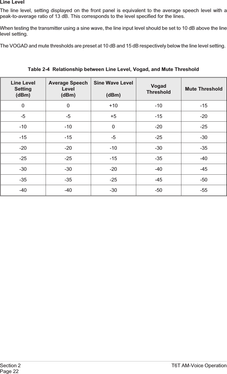
![6. Setting the Line Level.[Factory default setting: -13 dBm]The audio line level can be set to any value between -40 dBm and 0 dBm. Some notes regardingthe optimum line level are given on page 22.From the Function menu, turn the switchclockwise until Line Level is highlighted, thenpress the switch.Check that the Line Level menu is displayedand that Line Lvl is highlighted, then press theswitch.Turn the switch clockwise or anti-clockwise toincrease or decrease the value. When therequired value is displayed, press the switch.Turn the switch to highlight OK and then pressthe switch. You are returned to the Functionmenu.7. Setting the Output Power.[Factory default setting: 50 W]The transmitter's output power can be set to any value between 5 watts and 50 watts (in one wattsteps).From the Function menu, turn the switchclockwise until Power is highlighted, thenpress the switch.Ensure that the Power menu is displayed andthat Power is highlighted.Press the switch. Turn the switch clockwise toincrease the power, or anti-clockwise todecrease the power. When the required valueis displayed, press the switch. Turn the switchclockwise until OK is highlighted, then pressthe switch. You are returned to the Functionmenu.T6T AM-Voice Operation Section 2Page 31Inhibi tLine LevelPowe r<< >>Line Lvl -13dBmCance l OKInhibi tLine LevelPowe r<< >>Powe r 50WCance l OK](https://usermanual.wiki/Park-Air-Systems/B6350/User-Guide-92368-Page-63.png)
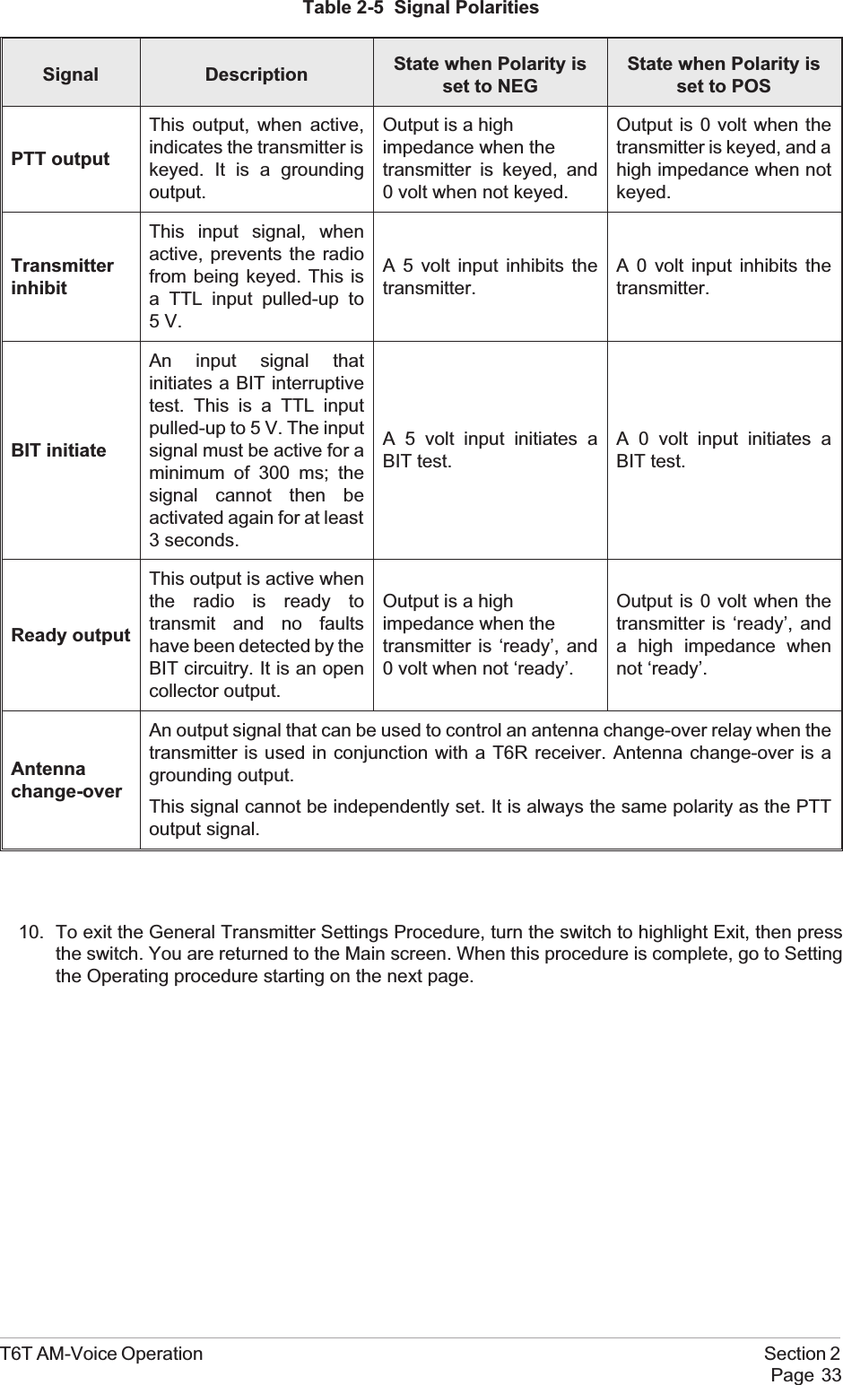
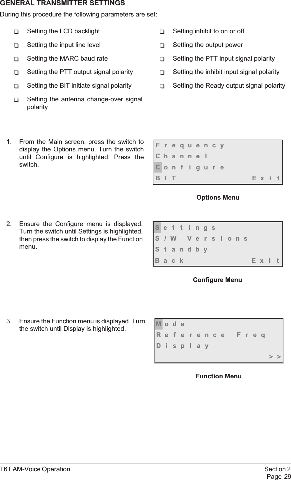
![8. Setting the MARC Baud Rate.[Factory default setting: 9600]The baud rate must be set when the T6T transmitter is connected to a MARC system (or othercompatible data and control system). The rate can be set to 300, 600, 1200, 2400, 4800, or 9600baud. The standard setting for MARC systems is 9600 baud.From the Function menu, turn the switchclockwise until MARC is highlighted, thenpress the switch.Ensure that the MARC menu is displayed andthat the Baud Rate is highlighted. Press theswitch.Turn the switch until the required value isdisplayed, then press the switch. Turn theswitch clockwise until OK is highlighted, thenpress the switch. You are returned to theFunction menu.9. Polarity Settings.The polarity of the following input and output and output signals is set using the Polarity menu:qPTT input signalqPTT output signalqInhibit input signalqBIT initiate input signalqReady output signal.In addition to the signals listed, the polarity ofthe Antenna Change-Over signal isdetermined from this menu. It is always thesame polarity as the PTT output signal.To establish the required polarity for the PTTinput signal, refer to the illustrations starting onpage 11 under the heading ‘Remote Keying Configurations’. Note that internal links must also becorrectly configured to obtain the required input PTT configuration.To establish the required polarity for the other input and output signals, refer to table 2-5.To set the required polarity, turn the switch to highlight the required parameter, then press theswitch to toggle between NEG and POS.Section 2 T6T AM-Voice OperationPage 32MARCPo l a r i t yBackEx i t <<Baud Rate 9600Cance l OKPTT I n NEGPTT Ou t POSInhibi t NEG>>BIT Ini t NEGReady Out POSBackEx i t <<Polarity Menu](https://usermanual.wiki/Park-Air-Systems/B6350/User-Guide-92368-Page-64.png)