Park Air Systems B6350 50W VHF Ground to air transmitter User Manual T6T User Guide vp
Park Air Systems Limited 50W VHF Ground to air transmitter T6T User Guide vp
Exhibit D User guide
T6T Transmitter User Guide
Issue 1

Handbook Title: T6T Transmitter User Guide
Handbook Part Number: 31-360000TX
Issue Number: 1
Date of Issue: November 1999
Published By: Park Air Electronics
Northfields
Market Deeping
Peterborough
England PE6 8UE
Telephone: From UK, 01778 345434
From outside UK, 44 1778 345434
Fax: From UK, 01778 342877
From outside UK, 44 1778 342877
Page ii

Handbook Amendment Record
Amendments to this handbook, originated by Park Air Electronics, are listed in the following table.
Amendment
Number Date Brief Details PAE Change
Note Number
Equipment Modification Record
Modifications to the T6T transmitter are detailed in the following table.
The equipment’s modification label shows modifications embodied in the equipment.
Modification
Number Date Brief Details PAE Change
Note Number
Page iii

List of Abbreviations
The following abbreviations are used in this user guide:
Page iv
A amp
AM amplitude modulation
BIT built-in test
dB decibel
DSP digital signal processing
ETI elapsed time indicator
ICAO international civil aviation organisation
kg kilogram
kHz kilo Hertz
LCD liquid crystal display
mA milliamp
MARC multi-access remote control system
MHz mega Hertz
mm millimetre
ppm parts per million
PSK phase shift keying
rms root mean square
RSSI receiver signal strength indication
V volt
VFP virtual front panel
VHF very high frequency
T6T Transmitter User Guide
Section 1
General Information

Section 1 T6T Transmitter User Guide
Page 2
Section 1 Contents
Chapter 1. Overview
Introduction to the T6T Transmitter 3
T6T Handbooks 3
Operational Settings 4
Virtual Front Panel 5
Built-In Tests 5
Transmitter Variants 6
Configuring the T6T Transmitter 6
Chapter 2. Specification
Dimensions and Weight 9
RF Characteristics 9
Environmental 10
Power Requirements 10
Chapter 3. Controls, Indicators, and Connectors
Front Panel 11
Transmit Indicator 11
Alarm Indicator 11
Ready Indicator 11
Standby Indicator 12
Reference Connector 12
Microphone/Diagnostics Connector 12
Scroll/Select Switch and LCD 13
Rear Panel 14
Power Switch 14
AC Input Connector 14
DC Input Connector 15
Fuse F1 15
Chassis Stud Connection 15
Facilities Connector CN5 15
MARC Port CN6 16
Computer Port CN7 16
Antenna Connector 16
Chapter 4. Installation Procedures
Introduction 21
Initial Inspection of the Transmitter 22
Fitting the Correct AC Input Fuse 22
Selecting the Correct AC Input Tap 23
Selecting the Keying Method 24
Fitting a Radio into an Equipment Rack 25
Connecting Remote Facilities 25
Chassis Stud Connection 26
AC Supply Connection 26
DC Supply Connection 27
Connecting an Antenna 27
Switching On 27
Page

Chapter 1. Overview
This chapter provides an introduction to the T6T transmitter, briefly describes the features, and
shows how the radio is configured for operational use.
INTRODUCTION TO THE T6T TRANSMITTER
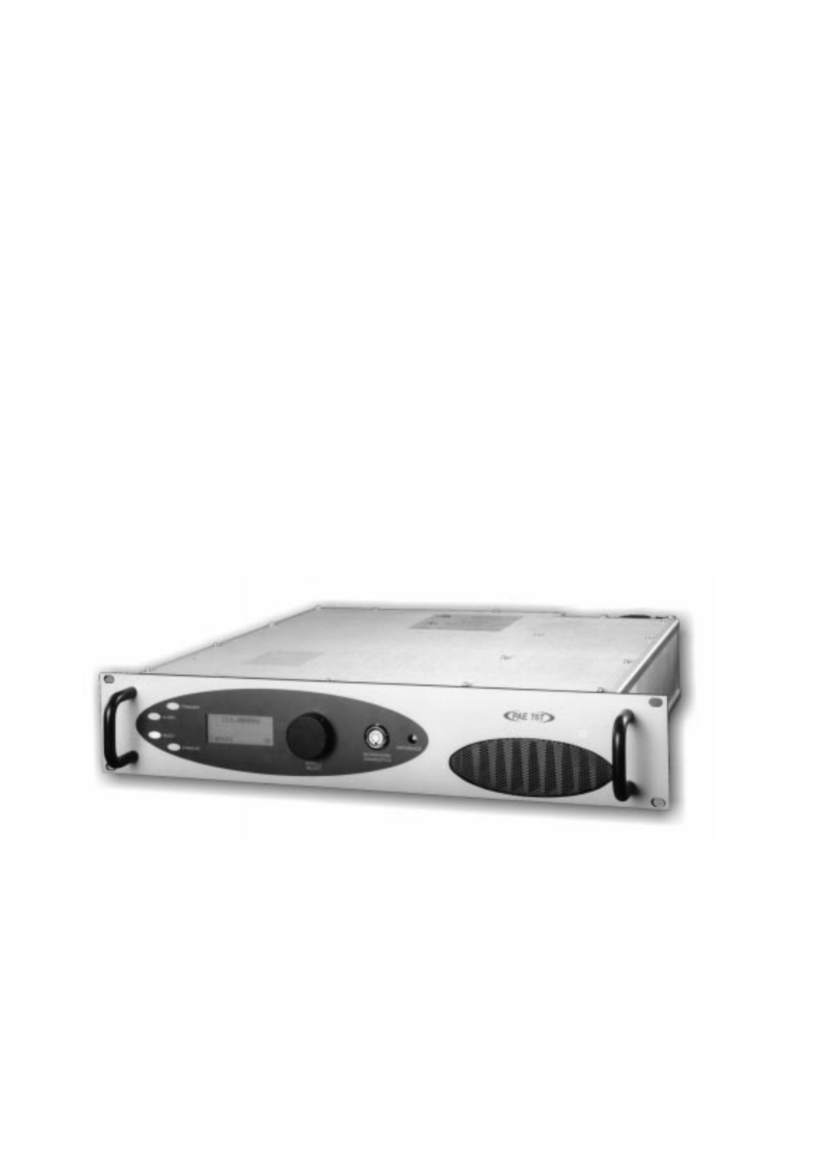
Park Air Electronics (PAE) T6T is a VHF multi-mode air-traffic control transmitter compatible with
analogue (AM) and digital (D8PSK) modulation modes. Current models are supplied programmed for
AM voice operation in the frequency range 118 to 136.975 MHz using 25 kHz or 8.33 kHz channel
spacing. Future software upgrades will allow D8PSK operation.
The transmitter produces a 50 watt carrier output that can be reduced, in 1 watt steps, to 5 watts. The
output power, and the majority of operational settings, can be selected at the front panel, using the virtual
front panel (VFP) or through a compatible control and data system such as the PAE multi-access remote
control (MARC) system.
A multi-channel feature allows up to 100 frequency channels to be stored and recalled by channel
number.
The transmitter is designed to be fitted in an industrial 19 inch (483 mm) equipment rack. Operation is
from either a standard ac mains supply, or from a low voltage dc supply. When both input supplies are
connected, the dc supply acts as a back-up if the mains supply fails.
Comprehensive continuous and interruptive Built-In Tests (BIT) provide confidence of the transmitter's
serviceability.
T6T HANDBOOKS
This user guide describes the T6T transmitter and gives complete installation and setting up procedures.
The user guide is split into sections as follows:
Section 1. Section 1 (this section) provides general information that is common to all
operating modes.
Section 2. Section 2 provides information that is specific to operating the T6T transmitter
in AM-voice mode.
Section 3. Section 3 onwards will, when available, describe the digital operating modes.
A maintenance kit (PAE part number 70-6350MKIT) is also available. A maintenance handbook,
included in the kit, contains fault finding guides to module level and details VFP operation. The VFP can
be used for setting up, maintenance purposes, and for loading new software.
The maintenance kit includes a CD-ROM containing the VFP software and a lead for connecting the
radio to a Personal Computer (PC). The CD-ROM also contains the software as loaded into the T6T at
the time of sale. This enables the original software to be re-loaded if the transmitter's Digital Signal
Processing (DSP) module is ever replaced.
Both the user guide and maintenance handbook are available on CD ROM. Contact PAE for details.
T6T General Information Section 1
Page 3
T6T transmitter maintenance should not be attempted without reference
to the maintenance handbook

OPERATIONAL SETTINGS
Operational settings for the T6T transmitter are configured at the front panel, through the VFP, or
through an associated MARC system (or compatible control and data system). At the transmitter,
operational settings are selected and displayed using the front panel Scroll/Select switch and the LCD.
The settings are selected through a series of menus. Full details are given in the section of this user
guide applicable to the operating mode. Two example selection menus, Set Frequency menu and
Channel Storage menu, are shown below.
121 . 500MHz
Cance l OK
Ch100 121 . 500MHz
Cance l
Store
Store and End
During normal transmitter operation, the Main screen, shown below, is displayed. The screen shows the
operating frequency, the channel number (if the channel store facility is used), the carrier offset (if used in
AM-voice mode), and displays a graphical representation of instantaneous peak power.
Freq 123 . 000MHz
Chan 1
Offset +5.0kHz
Pwr IIIIIIIIIIII
Section 1 T6T Transmitter User Guide
Page 4
Freq 123.000MHz
Chan 1
Offset +5.0kHz
Pwr lllllllllll
Example Main
Screen
Example Set
Frequency Menu
Example Channel
Storage Menu

Virtual Front Panel
As an alternative to setting up the transmitter from the front panel, the T6T's virtual front panel (VFP)
software can be used. To use the VFP, an IBM™ compatible PC must be connected to the transmitter
(see Fig. 1-1). Using the VFP offers several advantages over setting up from a transmitter's front panel.
These are:
qWhen set up using the VFP, a profile of the transmitter's operational settings can be created.
The profile can then be used to automatically set up other radios within a system, or to reset a
radio should its DSP module ever be replaced.
qWhen using the VFP, the transmitter's front panel can be locked. This means that a
transmitter's settings cannot inadvertently be changed by tampering with the front panel
controls.
qA print-out of a transmitter's profile (all the operational settings) can be made from the VFP.
Instructions on VFP usage is outside the scope of this user guide. Reference, therefore, should be made
to the T6T maintenance handbook that is supplied with a CD-ROM containing the VFP software.
BUILT-IN TESTS
The transmitter continuously self monitors key internal parameters without affecting normal operation. If
a BIT fault is detected, the front panel Alarm indicator lights, the Ready indicator becomes unlit, and the
transmitter becomes inoperable.
Additionally, a BIT warning, as opposed to a BIT fault may be indicated. A BIT warning is shown by the
front panel Alarm indicator flashing; the Ready indicator remains lit and the transmitter remains
operational, but at reduced power.
Apart from continuous monitoring, an interruptive BIT test can be initiated locally at the front panel, or
remotely. When initiated, test signals are injected that key the transmitter allowing parameters to be
monitored in their active state.
The results of continuous monitoring, and of interruptive testing, are available at the front panel LCD.
When the transmitter is used with a MARC system (or other compatible data and control system) the
results are also sent, in the form of a data message, to the monitoring facility. A full description of the BIT
facilities is given in the section applicable to the required operating mode. The following two illustrations
show example front panel BIT displays.
T6T General Information Section 1
Page 5
VSWR PASS
PA T emp 8 0 °C
Syn t h Lock Pass
<< >>
RF D r i v e PASS
Fwd Powe r 2 5W
Rf l Power 2W
<< >>

TRANSMITTER VARIANTS
Two variants of the T6T transmitter are available:
qB6350. This model operates in all modes except in AM-voice when using a 5-carrier offset.
The frequency stability of this model is 1 ppm.
qB6350OPT1. This model operates in all modes including AM-voice when using a 5-carrier
offset. The frequency stability of this model is 0.25 ppm.
CONFIGURING THE T6T TRANSMITTER
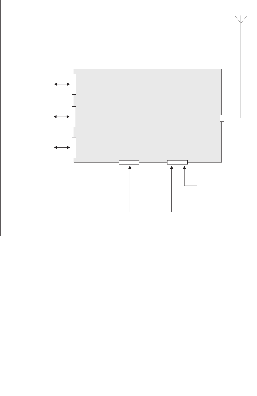
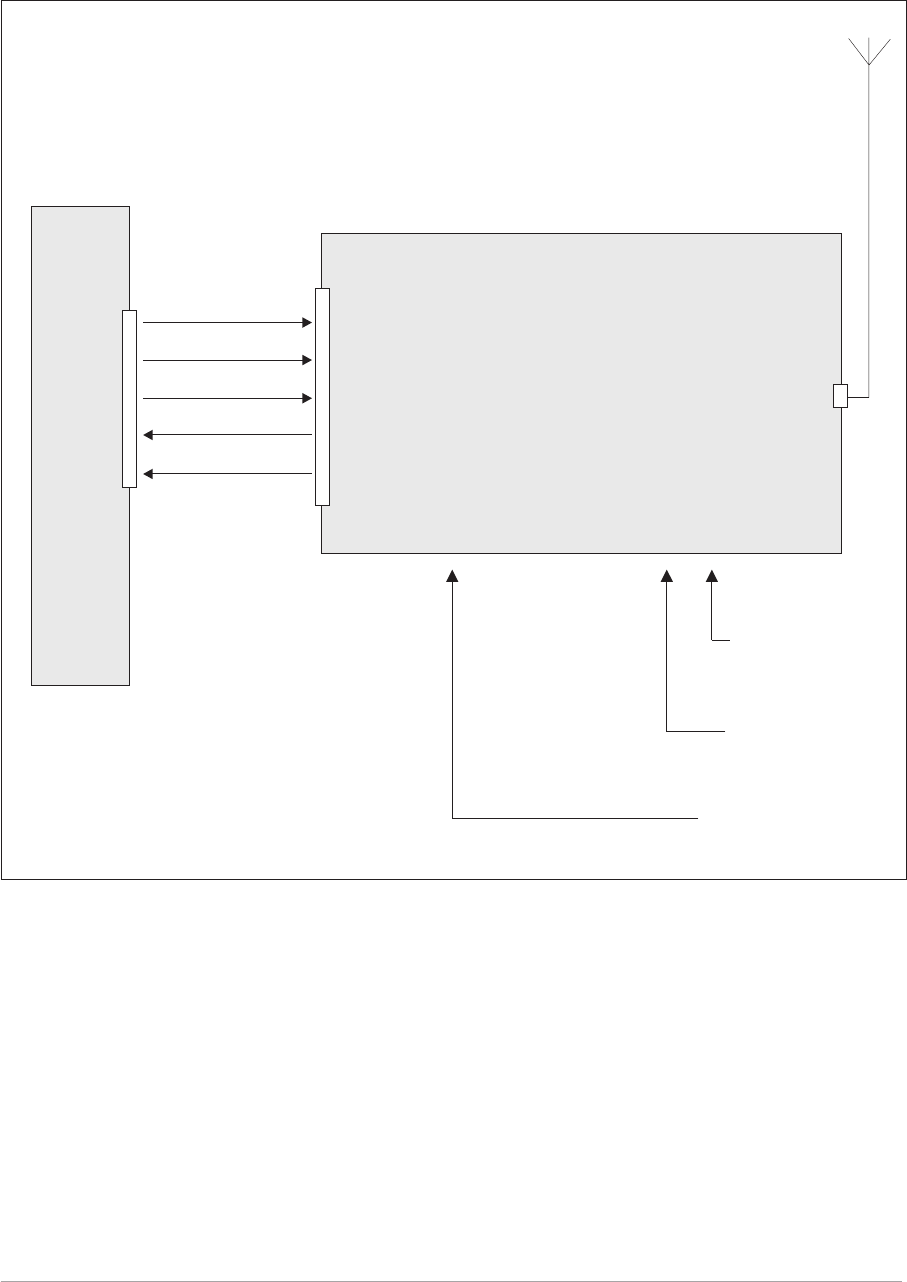
Fig. 1-1 shows the signal connectors fitted to the transmitter's front and rear panels. The connectors
used to configure the transmitter depend on the required operating mode. The purpose of each
connector is briefly described in the following paragraphs and fully detailed in chapter 3 starting on
page 11.
Antenna Connector Used in all operating modes to connect the 50 ohm antenna feeder
cable.
Microphone/Diagnostics
Connector
This is a dual purpose connector. A microphone/headset (complete with
integral PTT switch) can be connected to enable local AM-voice
operation.
Alternatively, a PC can be connected to allow use of the VFP. The VFP
can be used to set the transmitter's operational settings, or to download
new software.
Reference Connector Used in all operating modes to check and reset the transmitter's
reference frequency.
Facilities Connector Used primarily to connect remote signals when using AM-voice mode
when the transmitter does not form part of a MARC system.
Some auxiliary signals available at this connector, for example the
24 volt (nominal) unregulated output supply, can be utilized irrespective
of the operating mode.
MARC Port The MARC port is used to connect remote signals when the transmitter
forms part of a MARC system, or other compatible control and data
system.
Computer Port The computer port is used in digital communication modes to connect
the transmitter to a control computer.
Section 1 T6T Transmitter User Guide
Page 6
T6T General Information Section 1
Page 7
Fig. 1-1. T6T Transmitter Configuration
T6T Transmitter
Antenna
Connector
Microphone/Diagnostics
Connector
Microphone/headset
for local AM operation.
PC to allow use of the VFP
and to download new
software.
Reference
Connector
Frequency counter for
maintenance purposes.
Facilities
Connector
Remote Signals.
Computer
Port
Signals to/from a control
computer. Used when
operating in digital
communication modes.
MARC
Port
Signals to/from an
RSE 2 equipment. Used
when the radio forms
part of a MARC system.

Intentionally Blank
Section 1 T6T Transmitter User Guide
Page 8

Chapter 2. Specification
This chapter contains the T6T transmitter's specification that is common to all operating modes.
Specifications relevant to specific operating modes are contained in the section applicable to the
required operating mode.
DIMENSIONS AND WEIGHT
The dimensions and weight of the T6T transmitter are:
Width 483 mm (19 inches).
Height 88.9 mm (3.5 inches). The height occupies 2U of
equipment cabinet space.
Depth (front panel to rear panel) 430 mm (16.9 inches).
Depth (front panel to rear of fan) 450 mm (17.7 inches).
Weight 15.6 kg (34.4 pounds)
RF CHARACTERISTICS
Frequency range 118 to 136.975 MHz.
Output carrier power The output power is adjustable between 5 and 50 watts.
Number of channels The transmitter has a multi-channel capability.
100 channels can be stored and recalled.
Frequency accuracy Better than 1 ppm for transmitter B6350.
Better than 0.25 ppm for transmitter B6350OPT1.
Protection Excessive VSWR. The transmitter will transmit at full
power into a VSWR of up to 2.5 :1. At a higher VSWR
the output power will be reduced by 10 dB ±1 dB, if
necessary, in order to protect the transmitter.
Provision is made via the facilities port to allow an
external VSWR signal to be monitored. This is required
when isolators are employed which shield the transmitter
from a VSWR fault at the antenna.
PA Overheating. If the RF PA temperature exceeds
80°C, the output power is reduced by 6 dB ±1 dB and a
BIT warning indicated.
If the RF PA temperature exceeds 90°C the transmitter
de-keys and a BIT alarm is indicated.
T6T General Information Section 1
Page 9

Control Loop Error. If the cartesian control loop goes
out of limits, for example, due to low supply volts, the
output power gradually reduces by up to 3 dB until the
loop regains stability. If this fails to stabilise the loop the
transmitter de-keys and a BIT alarm is indicated.
Harmonic outputs Harmonic outputs are below -36 dBm.
ENVIRONMENTAL
Temperature range The transmitter operates to specification at temperatures
between -20 and +55°C and at a relative humidity
between 5% and 90% (non-condensing).
Duty cycle 100%.
Warm up time The transmitter is fully operational 5 seconds after
switch on.
Storage The transmitter can be stored at temperatures between
-30 and +70°C without causing damage.
Cooling The transmitter has an integral cooling fan.
POWER REQUIREMENTS
The transmitter operates from an ac input supply, or a dc input supply. When both supplies are
connected, the dc input acts as an automatic backup supply for the ac mains.
ac input supply The transmitter operates from a 48 to 62 Hz
single-phase ac supply.
The input voltage, measured at the equipment, can be
110/120/220/230/240 V ac (± 10%). The correct ac
input tap must be selected to suit the input voltage.
Additionally, the correct ac input fuse F2 must be fitted.
See installation detail on page 23.
ac power consumption Typically 330 VA. 500 VA maximum.
dc input supply Between 21.6 and 32 V. Full output power capability is
maintained with a dc input between 24 and 32 V. From
24 down to 21.6 V the output power gradually
decreases.
dc supply current 15 amp (maximum) with a 28 volt dc input supply.
Section 1 T6T Transmitter User Guide
Page 10

Chapter 3. Controls, Indicators, and Connectors
This chapter details the purpose of all controls, indicators, and connectors
fitted to the transmitter's front and rear panels.
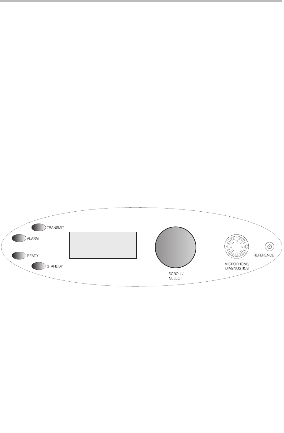
FRONT PANEL
The front panel's controls, indicators, and connectors are shown below and described in the following
paragraphs.
Transmit Indicator
An amber indicator that lights when the transmitter is keyed and producing output power.
Alarm Indicator
A red indicator that either flashes, or lights, when a BIT fault has been detected. BIT indications are
classified as either warnings or faults.
If a warning is detected, the Alarm indicator flashes, the Ready indicator remains lit, and the transmitter
remains operational. A BIT warning is indicated if:
qa high PA temperature is sensed
qa high VSWR is sensed.
If a fault is detected, the Alarm indicator lights and the Ready indicator becomes unlit; the transmitter
cannot be used.
Ready Indicator
A green indicator that lights when the transmitter is ready for use and no BIT faults have been detected.
T6T General Information Section 1
Page 11
Freq 123.000MHz
Chan 1
Offset +5.0kHz
Pwr lllllllllll

Standby Indicator
A red indicator that lights when the transmitter is in standby mode. When in standby mode, most of the
transmitter's circuits are inactive, the front panel LCD is blanked, and the transmitter cannot be keyed.
Standby mode is selected and deselected using the front panel Scroll/Select switch and LCD, by
initiating an instruction through a MARC system, or through the VFP. Details of front panel selection and
deselection are given in the section of this user guide applicable to the particular operating mode.
Reference Connector
An SMB jack socket that allows a high impedance frequency counter to monitor the transmitter's
reference frequency. This connector is used only for maintenance purposes. The instructions for
checking and adjusting the reference frequency are given in the T6T maintenance handbook.
Microphone/Diagnostics Connector
A dual purpose connector that allows either a dynamic
microphone (and headset if sidetone is required) or a PC to be
connected to the transmitter. The connector is a 7-pin self
locking DIN socket.
A microphone/headset with integral PTT switch can be fitted to
this connector to enable the transmitter to be operated in local
mode. The connections are detailed in table 1-1. A PC can also
be connected to allow the VFP to be displayed. Using the VFP is
detailed in the T6T maintenance handbook. The connections at
the transmitter are shown in table 1-2.
Table 1-1. Microphone/Headset Connections
Headset/Diagnostics
Connector Pin Number Signal Notes
1 Microphone ground 0 volt.
3 Microphone PTT 0 volt = PTT. 5 V pull-up = not PTT.
5 Sidetone to headset 200 ohm output impedance.
Maximum = 3 volt peak-to-peak.
6 Microphone input 6.8 kohm, 5 mV sensitivity.
Section 1 T6T Transmitter User Guide
Page 12
Fig. 1-2.
Microphone/Diagnostics
Connector Pin-Out
(DEV083-05)

Table 1-2. Diagnostics PC Connections
Headset/Diagnostics
Connector Pin Number Signal Notes
2 Transmit data RS232
4 Receive data RS232
7 Ground 0 volt
Scroll/Select Switch and LCD
The Scroll/Select switch is used in conjunction with the LCD to select most of the transmitter's
operational settings. Use of the switch and LCD is fully detailed in the section of this user guide
applicable to the particular operating mode. During normal operation, the LCD shows the operating
frequency, the channel number (if the channel store facility is used), the carrier offset (if used), and
displays a graphical representation of instantaneous peak power.
The example LCD screen below shows the transmitter operating on 123.000 MHz; the frequency has
been preset as channel 8; and no offset is used.
Freq 123 . 000MHz
Chan 8
Pwr IIIIIIIIIIII
T6T General Information Section 1
Page 13
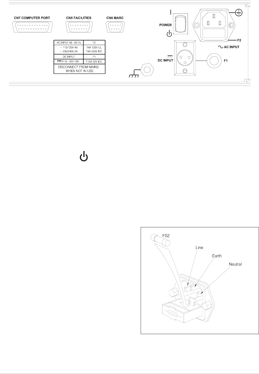
REAR PANEL
The rear panel's controls, indicators, and connectors are shown in Fig. 1-3 and described in the following
paragraphs.
Power Switch
A 2-way rocker switch used to switch on, and switch off, power to the transmitter's circuitry.
l=On
WARNING!
When the POWER SWITCH is set to the Off position, lethal voltages are still present in the
transmitter's internal power supply circuitry. To ensure safe working, the ac and dc input
supplies must be disconnected from the transmitter.
AC Input Connector
A 3-pole IEC chassis plug for connecting the ac input
supply. The plug has an integral 20 mm fuse (F2) that
protects the Line (L) input circuit. The fuse is rated at
4 amps. Detailed instructions regarding fuse types,
and connecting the ac supply are given in the
installation chapter on page 26.
Caution!
Before connecting an ac input supply to the
transmitter, the ac input taps must be set to suit
the local mains supply (see page 22).
Section 1 T6T Transmitter User Guide
Page 14
(DEV083-02) Fig. 1-3. Rear Panel
= Off
Fig. 1-4. AC Mains Connector
(SA3536)
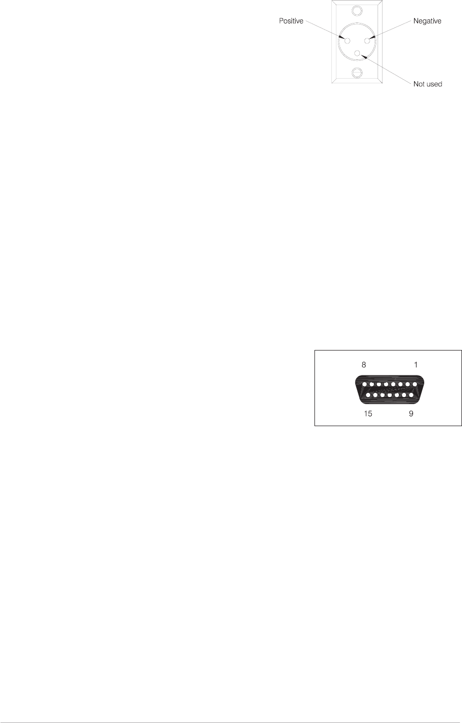
DC Input Connector
A 3-pole chassis plug for connecting the dc input supply.
Detailed instructions for connecting the dc supply are given
in the installation chapter of this handbook on page 27.
Fuse F1
Fuse F1 protects the dc input positive supply circuit. It is a Size 0 fuse rated at 15 amps. The PAE part
number of the fuse is: 29-01350201.
Chassis Stud Connection
The chassis stud is used to provide a common earth point between the transmitter and the associated
equipment rack, or the transmitter and the user's system earth. The stud must not be used as a safety
earth. Connection details are given on page 26.
Facilities Connector CN5
A 15-way D-type socket used primarily to connect remote signals when the transmitter operates in AM
mode and does not form part of a MARC (or similar) system. The pin-out of this connector is given in
table 1-3 on page 17.
Apart from allowing connection of remote signals, this connector
makes some auxiliary signals available to the user. For example, a
24 volt (nominal) unregulated output supply. The auxiliary signals
can be employed by the user as and when required irrespective of
the operating mode.
Facilities connector CN5 as seen when looking at the rear panel.
Connections should be made using a 15-way D-type plug PAE part
number: 20-01150100 (plug), and 20-09150101 (cover). These are
supplied with the transmitter as item 3 (see page 22).
T6T General Information Section 1
Page 15
Fig. 1-5. DC Connector
(DEV083-06)
Fig. 1-6. Facilities Connector
CN5 Pin-Out

MARC Port CN6
A 9-way D-type socket used to connect remote signals to a MARC system or other compatible control
and data system. The pin-out of this connector is given in table 1-4 on page 18.
Computer Port CN7
A 25-way D-type socket used to connect the transmitter to a control computer when the transmitter is
operated in digital communication modes. The pin-out of this connector is given in table 1-5 on page 19.
Antenna Connector
An N-type 50 ohm coaxial socket used to connect the antenna's feeder cable.
Section 1 T6T Transmitter User Guide
Page 16
Fig. 1-7 MARC Port CN6 Pin-Out
MARC connector CN6 as seen when looking at the rear panel.
Connections should be made using a 9-way D-type plug PAE part
number: 20-01090100 (plug), and 20-09090101 (cover).
Fig. 1-8 Computer Port CN7 Pin-Out
Computer port CN7 as seen when looking at the rear panel.
Connections should be made using a 25-way D-type plug PAE part
number: 20-01250100 (plug), and 20-09250101 (cover).

Table 1-3. Facilities Connector CN5 Pin-Out
Pin
Number Signal Name Description
1 Ground 0 volt.
2 Line In (+) Pins 2 and 3 present a 600 ohm balanced audio input to the
transmitter for use in AM modes. The input level is adjustable
between -40 dBm and 0 dBm. Phantom keying can be
superimposed on the audio lines. See ‘Selecting the Applicable
Keying Method’ in section 2 on page 10.
3 Line In (-)
4 External VSWR
An input signal to the transmitter to indicate a VSWR fault in the
antenna circuit. When this signal is active, the transmitter's output
power is reduced by 10 dB and a VSWR warning is indicated. This
is a TTL input pulled-up to 5 V; the active signal is 0 volt.
5Antenna
Change-Over
An output signal that can be used to control an antenna
change-over relay when the transmitter is used in conjunction with a
T6R receiver. Antenna change-over is a grounding output; the
active (transmitter keyed) polarity is always the same as the PTT
output signal on pin 6. Maximum current sink is 100 mA.
6 PTT Output
This output, when active, indicates the transmitter is keyed. It is a
grounding output. The active polarity is set from the front panel.
Maximum current sink is 100 mA.
7 Remote PTT
An input signal used to key the transmitter. The active signal can be
0 volt, or a dc level between +10 and +50 volt, or a dc level between
-10 and -50 volt. Internal jumpers JP8 and JP9 must be correctly set to
suit the required keying potential (see ‘Remote Keying Configurations’
in section 2 on page 11). The active polarity is set from the front panel.
8 Ground 0 volt.
9 Unregulated Supply A dc output supply between 21.6 and 32 volt. The supply is fused
at 500 mA.
10 Tx Inhibit
This input signal, when active, prevents the radio from being
keyed. This is a TTL input pulled-up to 5 V; the active polarity is set
from the front panel.
11 BIT Interruptive Test
An input signal that initiates a BIT interruptive test. This is a TTL
input pulled-up to 5 V. The active polarity of this signal is set from
the front panel. The input signal must be active for a minimum of
300 ms; the signal cannot then be activated again for at least
3 seconds.
12 Not Used Pin 12 is internally connected. Do not make any connections to
this pin.
13 Ready Output
This output is active when the radio is ready to transmit and no
faults have been detected by the BIT circuitry. It is an open
collector output. The active polarity is set from the front panel.
14 Tape Output An audio output for connection to a recording system. The output
is nominally -10 dBm into 100 ohm.
15 Not Used -
T6T General Information Section 1
Page 17

Table 1-4. MARC Connector CN6 Pin-Out
Pin
Number Signal Name Description
1 Ground 0 volt.
2 Line In (+) Pins 2 and 3 present a 600 ohm balanced audio input to the
transmitter for use in AM modes. The input level is
adjustable between -40 dBm and 0 dBm. Phantom keying
can be superimposed on the audio lines. See ‘Selecting the
Applicable Keying Method’ in section 2 on page 10.
3 Line In (-)
4 PTT
An input signal used to key the transmitter. The active
signal can be 0 volt, or a dc level between +10 and +50 volt,
or a dc level between -10 and -50 volt. Internal jumpers JP8
and JP9 must be correctly set to suit the required keying
potential (see ‘Remote Keying Configurations’ in section 2
on page 11). The active polarity is set from the front panel.
5 Unregulated Supply
A dc output supply between 21.6 and 32 volt. The supply,
which is fused at 500 mA, is used as the power source for
the MARC RSE 2 equipment.
6 Data In (+) RS422 data line.
7 Data In (-) RS422 data line.
8 Data Out (+) RS422 data line.
9 Data Out (-) RS422 data line.
Section 1 T6T Transmitter User Guide
Page 18

Table 1-5. Computer Port CN7 Pin-Out
CN7 Pin Number Signal Name Level Input or Output
1 Ground 0 volt -
2 Serial 0 TXA RS422 Output
3 Serial 0 TXB RS422 Output
4 Serial 0 RXA RS422 Input
5 Serial 0 RXB RS422 Input
6 Serial 0 CLA RS422 Output
7 Serial 0 CLB RS422 Output
8 Serial 1 TXA RS422 Output
9 Serial 1 TXB RS422 Output
10 Serial 1 RXA RS422 Input
11 Serial 1 RXB RS422 Input
12 Serial 1 CLA RS422 Output
13 Serial 1 CLB RS422 Output
14 Input A RS 232 Input
15 Input B RS232 Input
16 Input C RS232 Input
17 Input D RS232 Input
18 Output A RS232 Output
19 Output B RS232 Output
20 Output C RS232 Output
21 Output D RS232 Output
22 Ground 0 volt -
23 Not used - -
24 Not used - -
25 Not used - -
T6T General Information Section 1
Page 19

Intentionally Blank
Section 1 T6T Transmitter User Guide
Page 20

Chapter 4. Installation Procedures
This chapter details the installation procedures for a T6T transmitter that are necessary irrespective of
which operating mode is to be used.
WARNING. LETHAL VOLTAGES!
The instructions given in this chapter involve connecting lethal voltages to the
transmitter. The instructions detailed in this chapter must be carried out only by suitably
qualified personnel.
WARNING. ANTENNA RADIATION!
The antenna used with the transmitter must be installed such that the resultant radiated
field strength is below 10 W/m² in areas normally accessible to personnel.
WARNING. BERYLLIUM/BERYLLIA!
The equipment covered by this handbook contains components containing the highly
toxic material Beryllium and/or its oxide Beryllia. These materials are particularly
hazardous if:
1. Beryllium materials are absorbed into body tissues through the skin, mouth,
or wound.
2. The dust created by breakage of Beryllia is inhaled.
3. Toxic fumes are inhaled from Beryllia/Beryllium involved in a fire.
The components containing Beryllia/Beryllium are: TR5, TR6 and TR9 in the
PA module.
WARNING. UNAUTHORIZED MODIFICATIONS!
Changes or modifications made to this equipment that are not expressly approved by
Park Air Electronics, or parties authorized by Park Air Electronics, could void the user’s
authority to operate the equipment.
CAUTION. ESSDs!
The T6T transmitter's circuitry contains Electrostatic Sensitive Devices (ESSDs).
Personnel must be aware of the precautions necessary to prevent damage to such
devices. During installation all precautions necessary to prevent ESSD damage must be
taken.
INTRODUCTION
The procedures in this chapter describe how to install a T6T transmitter. The procedures necessary
during installation are listed in table 1-5 and should be completed in the order shown.
T6T General Information Section 1
Page 21

Table 1-5 Installation Procedures
Procedure Reference
1 Perform an initial inspection of the transmitter. Page 22
2 Fit the correct ac input fuse. Page 22
3 Select the correct ac input tap. Page 23
4 Selecting the keying method (AM-voice only) Page 24
5 Fit the transmitter into an equipment rack. Page 25
6 Connecting remote facilities Page 25
7 Connect the chassis stud to the rack or system earth. Page 26
8 Connect the ac input supply (if applicable). Page 26
9 Connect the dc input supply (if applicable). Page 27
10 Connect an antenna. Page 27
INITIAL INSPECTION OF THE TRANSMITTER
On receipt of the transmitter from PAE, remove all transit packaging and check that there is no transit
damage. If damage is evident, contact PAE immediately and retain the original transit packaging.
The following items should be included with the transmitter:
Item 1. One copy of the T6T User Guide (this handbook).
Item 2. An unterminated IEC mains connector.
Item 3. An unterminated 15-way D-type plug (for use with the rear panel Facilities
connector CN5).
FITTING THE CORRECT AC INPUT FUSE
The mains input fuse F2 is an integral part of the rear panel ac connector (the connector and fuse are
shown in Fig. 1-4 on page 14). The fuse type must be correct for the local mains supply. Check the fuse
fitted conforms to that detailed in Table 1-6.
Table 1-6 Input AC Fuse Rating
Mains Input Supply Fuse PAE Part Number
110/120 V T4A 125 V UL 29C11120102S
220/230/240 V T4A 250 V IEC 127 HBC 29E01120108S
Section 1 T6T Transmitter User Guide
Page 22
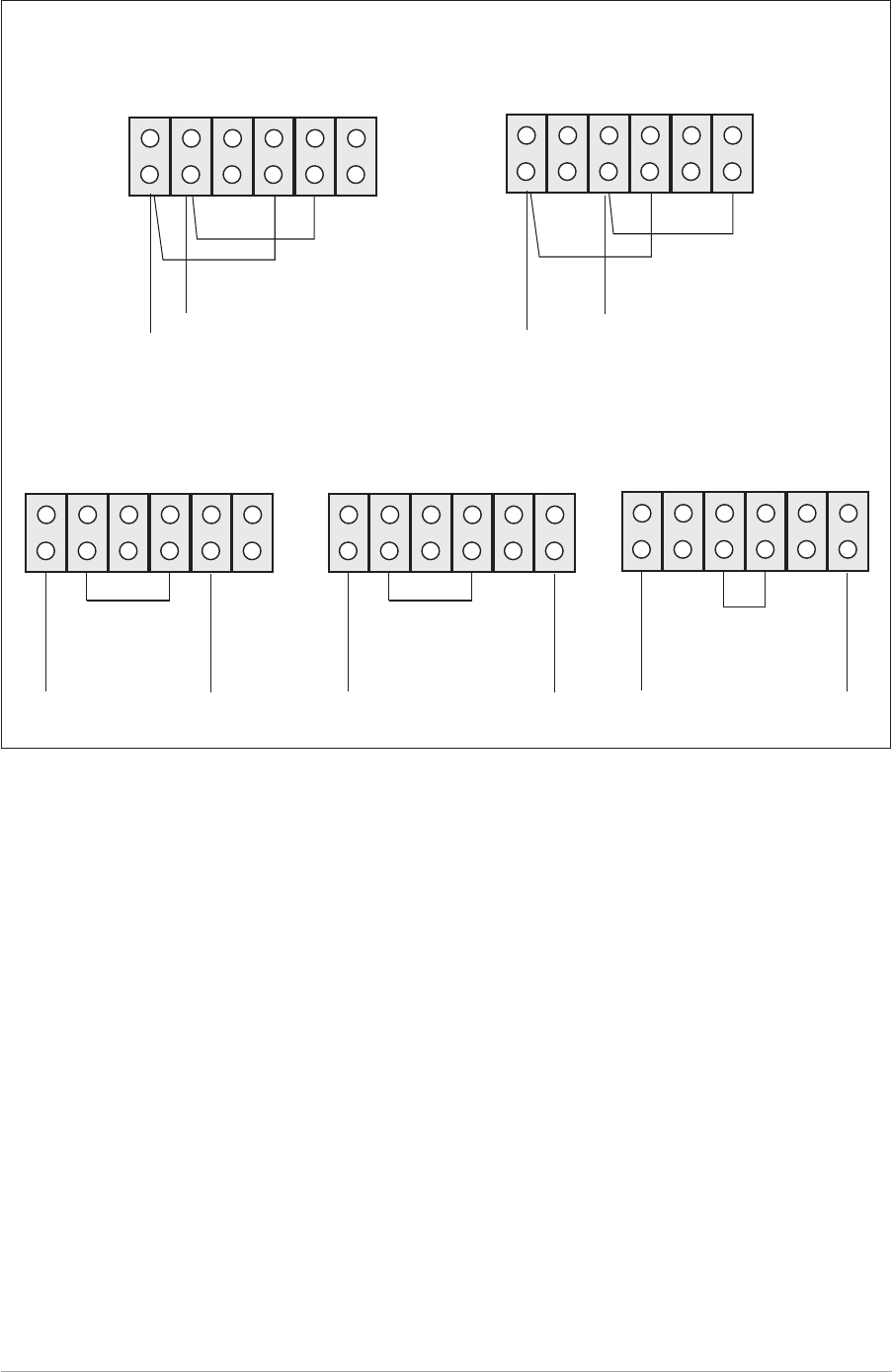
SELECTING THE CORRECT AC INPUT TAP
The correct tap on the input ac transformer must be selected to suit the local mains supply. The taps are
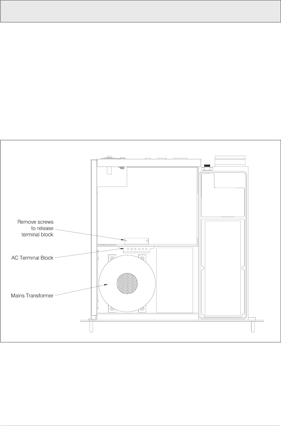
selected by configuring connections on the AC Terminal Block. To set the correct tap:
a. Release the M3 captive screws that secure the transmitter's top cover. Remove the cover. Refer
to Fig. 1-9 and identify the AC Terminal Block. Refer to Fig. 1-10 and identify the configuration that
is required for the local ac mains supply.
b. Remove the two screws that secure the terminal block bracket as shown in Fig. 1-9.
c. Connect the ac wires (brown = Line, and blue = Neutral) to the correct terminals. Connect link(s)
as shown in Fig. 1-10.
d. If the transmitter is to be operated in AM-voice mode, go to the next procedure. If operating in
other modes, refit the top cover.
T6T General Information Section 1
Page 23
Factory default setting. The transmitter is set for a 230 V ac input unless specified
otherwise at the time of ordering.
DEV083-08 Fig. 1-9. Location of Input Tap Terminal Block
SELECTING THE KEYING METHOD
This procedure is applicable only to AM-voice mode.
A number of different ‘remote’ or ‘phantom’ keying configurations are possible with the T6T transmitter.
Internal jumpers must be correctly set to suit the required configuration. To do this, refer to section 2,
chapter 3, of this user guide and follow the procedure ‘Selecting the Applicable Keying Method’.
Section 1 T6T Transmitter User Guide
Page 24
0 110 120 0 110 120
Blue Brown
Link
240 V ac Input220 V ac Input
0 110 120 0 110 120
Link
Blue Brown
230 V ac Input
0 110 120 0 110 120
Link
Blue Brown
Blue
Brown
0 110 120 0 110 120
Blue Link
Brown
Link
110 V ac Input
0 110 120 0 110 120
Blue
Link
Brown
Link
Blue
Brown
120 V ac Input
Fig. 10. Input Tap Selection
FITTING A RADIO INTO AN EQUIPMENT RACK
CAUTION!
It is essential that the chosen mechanical installation provides adequate support along
the depth (front to rear) of the unit. The transmitter must not be supported by the front
panel; doing so can cause damage.
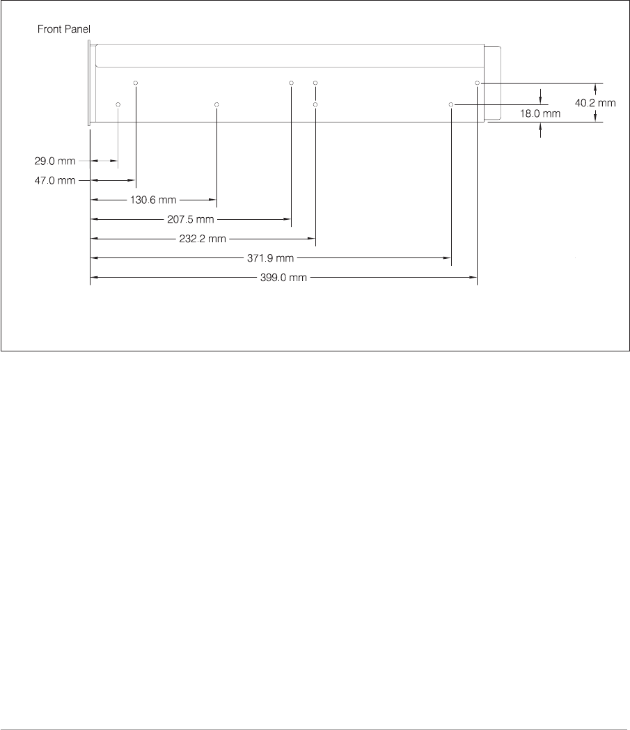
The transmitter can be installed on telescopic slides, or on fixed runners, within a standard 483 mm
(19 inch) equipment rack. M4 tapped holes, each 10 mm deep (see Fig. 1-11) are provided on each side
of the equipment to accept the slides. Details of suitable telescopic slides and fixed runners are available
from PAE.
When fitted in the rack, the transmitter's front panel must be secured to the racks chassis using four
M6 x 16 mm screws and plastic washers.
CONNECTING REMOTE FACILITIES
Remote facilities connections depend on the transmitter's operating mode. To determine the required
remote connections, refer to chapter 3 of the section applicable to the operating mode.
T6T General Information Section 1
Page 25
Fig. 1-11. Telescopic Slide Fixing Points
(DEV083-09)

CHASSIS STUD CONNECTION
WARNING. CHASSIS EARTH!
A chassis stud is fitted to the transmitter's rear panel. This stud is used to connect the
equipment to the equipment rack, or to the user's system earth point. The stud must not
be used as the safety earth.
In order not to compromise the transmitter’s Electromagnetic Compatibility (EMC) the chassis stud,
marked and fitted to the rear panel (see Fig. 1-3 on page 14) must be connected to the equipment
rack (if a rack is being used) or to the user's system earth point. The connection should be made using a
single tri-rated, green-and-yellow cable having a cross-sectional area of 2.5 mm2. The cable should have
CSA and UL1015 approval, and be connected to the chassis stud through an M6 eyelet (for example,
PAE part number 20-08010103).
Failure to comply with this instruction could result in non-compliance with the European
Commission EMC Directive 89/336/EEC.
AC SUPPLY CONNECTION
WARNING. LETHAL VOLTAGES!
The equipment is permanently connected to the mains supply when the mains
connector is attached. Switching the rear panel Power switch to off does not isolate all
internal circuits from the mains supply. For this reason, a mains isolating switch should
be fitted close to, and easily accessible from, the transmitter's position.
WARNING. EARTH CONNECTION!
This equipment must be earthed. The earth terminal of the AC connector should be used
as the safety earth.
An ac input connector (see Fig. 1-4 on page 14) is fitted to the equipment’s rear panel. The cable used to
connect between the equipment and the user’s ac power source should be 3-core (to IEC 227) rated
250 V ac at 8 amps, and have a minimum cross-sectional area of 1.0 mm² per core. PAE recommends
the use of polyvinyl chloride (PVC) insulated cable. The cable must be fitted with the IEC approved
equipment connector (PAE part number 20-02030102) supplied with the transmitter, and conform to the
following specification:
qIf PVC insulated, be not lighter than ordinary polyvinyl chloride sheathed flexible cord
according to IEC publication 227 (designation H05 VV-F, or H05 VVH2-F).
qIf rubber insulated, be of synthetic rubber and not lighter than ordinary tough rubber-sheathed
flexible cord according to IEC publication 245 titled ‘Rubber Insulated Cables of Rated
Voltages up to and Including 450/750 V (designation H05 RR-F)’.
The T6T transmitter is a Class 1 equipment. The ac supply cable should have a green-and-yellow
protective earthing conductor electrically connected to the protective earthing terminal of the equipment
connector and the mains plug. PAE recommends the ac supply cable is colour coded in accordance with
the electrical appliance (colour code) regulations for the UK. That is:
qThe core that is coloured green-and-yellow must be connected to the terminal in the plug that
is marked with the letter E or by the earth symbol or coloured green-and-yellow.
qThe core that is coloured blue must be connected to the terminal that is marked with the letter
N or coloured black.
qThe core that is coloured brown must be connected to the terminal that is marked with the
letter L or coloured red.
Section 1 T6T Transmitter User Guide
Page 26

DC SUPPLY CONNECTION
The transmitter operates from either an ac, or a dc input supply. When both ac and dc are connected,
operation from the ac supply takes priority; automatic change-over to the dc supply occurs if the ac
supply fails. On restoration of the ac supply, the equipment reverts to ac operation.
A dc input supply connector (see Fig. 1-5 on page 15) is fitted to the equipment's rear panel. The
recommended minimum rating of the dc supply cable is: 2-core having a cross-sectional area of 1.5 mm2
per core. The supply cable should be fitted with an XLR3 connector (PAE part number 20-01030106).
CONNECTING AN ANTENNA
The antenna feeder cable connects to the transmitter’s rear panel N-type antenna connector (see
Fig. 1-3 on page 14).
SWITCHING ON
When installation is complete, the transmitter should be switched on at the rear panel Power switch (see
page 14).
T6T General Information Section 1
Page 27
T6T Transmitter User Guide
Section 2
AM-Voice Mode

Section 2 T6T AM-Voice Operation
Page 2
Section 2 Contents
Chapter 1. AM-Voice Overview
Introduction to AM-voice mode 3
Carrier Offset Operation 3
Operational Settings 4
Basic Configuration 4
Local Operation 4
Remote Operation 5
Configuration for Operation with MARC 6
Chapter 2. AM-Voice Specification
RF Characteristics 7
Modulation Characteristics 7
Chapter 3. AM-Voice Installation
Introduction 9
Selecting the Applicable Keying Method 10
Remote Keying Configurations 11
Phantom Keying Configurations 12
Connecting the Remote Facilities 14
Connecting to MARC Equipment 14
Chapter 4. AM-Voice Operational Settings
Introduction 17
Normal Operation 17
Using the Scroll/Select Switch 17
Screen Protocol 18
Menu Lock Screen 20
Notes for Setting Up the Transmitter 21
Front Panel Display for 25 kHz and 8.33 kHz Channel Spacing 21
Line Level 22
To Enter Standby Mode 23
To Exit Standby Mode 24
AM Voice Settings Procedure 25
General Transmitter Settings 29
Setting the Operating Frequency 34
Allocating Channel Numbers to Specified Frequencies 35
To Recall Channel Frequencies 36
To initiate an Interruptive BIT Test 37
To View BIT Pages and Advise Screen 38
Elapsed Time Indicator 39
Displaying the Transmitter's Internal Reference Frequency Screen 40
Software Versions Screen 41
Page

Chapter 1. AM-Voice Overview
This chapter provides an introduction to using the T6T transmitter in AM-voice mode.
INTRODUCTION TO AM-VOICE MODE
In AM-voice mode, the T6T transmitter operates in the frequency range 118 to 136.975 MHz using
25 kHz or 8.33 kHz channel spacing. The transmitter produces a 50 watt carrier output that can be
reduced, in 1 watt steps, to 5 watts. The output power, and the majority of operational settings, can be
selected at the front panel or through a compatible control and data system such as the PAE
Multi-Access Remote Control (MARC) system.
A multi-channel feature allows up to 100 frequency channels to be stored and recalled by channel
number. In AM voice mode, and when 25 kHz channel spacing is used, the transmitter can operate with
a 2, 3, 4, or 5 carrier-offset frequency in accordance with ICAO Annex 10.
CARRIER OFFSET OPERATION
In AM voice mode the transmitter can offset the carrier frequency to provide 2, 3, 4, or 5-carrier offset to
meet the requirements of ICAO Annex 10. Offsets are selected using the front panel Scroll/Select control
and the LCD display. The offsets are:
2-carrier offset: carriers are spaced at ±5 kHz.
3-carrier offset: carriers are spaced at zero, and ±7.3 kHz.
4-carrier offset: carriers are spaced at ±2.5 kHz and ±7.5 kHz
5-carrier offset: carriers are spaced at zero, ±4 kHz and ±8 kHz
Note ...
For 5-carrier offset operation, transmitter variant B6350OPT1 must be used.
T6T AM-Voice Operation Section 2
Page 3

OPERATIONAL SETTINGS
Operational settings for the T6T transmitter are configured at the front panel, through the VFP, or
through an associated MARC system (or compatible control and data system). At the transmitter,
operational settings are selected and displayed using the front panel Scroll/Select switch and the LCD.
The settings that can be selected are:
qOperating frequency qSelecting a carrier offset
qSelecting the channel spacing qChannel allocation and recall
qSetting the line level qSetting the output power
qStandby mode to on or off qSetting inhibit to on or off
qSetting the MARC baud rate qSetting the PTT input signal polarity
qSetting the PTT output signal polarity qSetting the inhibit input signal polarity
qSetting the BIT initiate signal polarity qSetting the Ready output signal polarity
qSetting the antenna change-over signal
polarity qPTT test facility
qSetting the PTT timeout qSetting the modulation depth
qMute enable or disable qVogad enable or disable
qAdjusting the sidetone volume qSetting the LCD backlight
BASIC CONFIGURATION
Fig. 2-1 shows the basic T6T transmitter connections for AM voice operation. If the transmitter is part of a
MARC system, or other compatible control and data system, refer to ‘Configuration for Operation with
MARC’ on page 6.
Local Operation
In its simplest configuration, the transmitter can be operated in Local mode. This involves plugging a
microphone with integral PTT switch into the front panel Microphone/Diagnostics connector. The
transmitter is then operated from the front panel.
Section 2 T6T AM-Voice Operation
Page 4
Remote Operation
For remote operation signals are connected from the control equipment, through a suitable
communication link, to the transmitter's rear panel Facilities connector. Essential connections are an
audio input and a keying input. For the keying input, the Remote PTT connection can be used, or
phantom keying can be superimposed on the audio lines (see ‘Selecting the Applicable Keying Method’
in chapter 3). Other remote signals can be connected to suit the particular application. The remote
signals are fully described in section 1 on page 17.
In the basic configuration, the rear panel MARC and Computer Port connectors are not used. The front
panel Reference connector is used to check the transmitter's internal reference frequency during
scheduled maintenance. The front panel Microphone/Diagnostics connector has two purposes: a
microphone/headset is connected for local operation, or, a PC is connected for maintenance purposes.
Maintenance using a PC connected to the Headset/Diagnostics connector is outside the scope of this
user guide. Full information is contained in the T6T maintenance handbook.
T6T AM-Voice Operation Section 2
Page 5
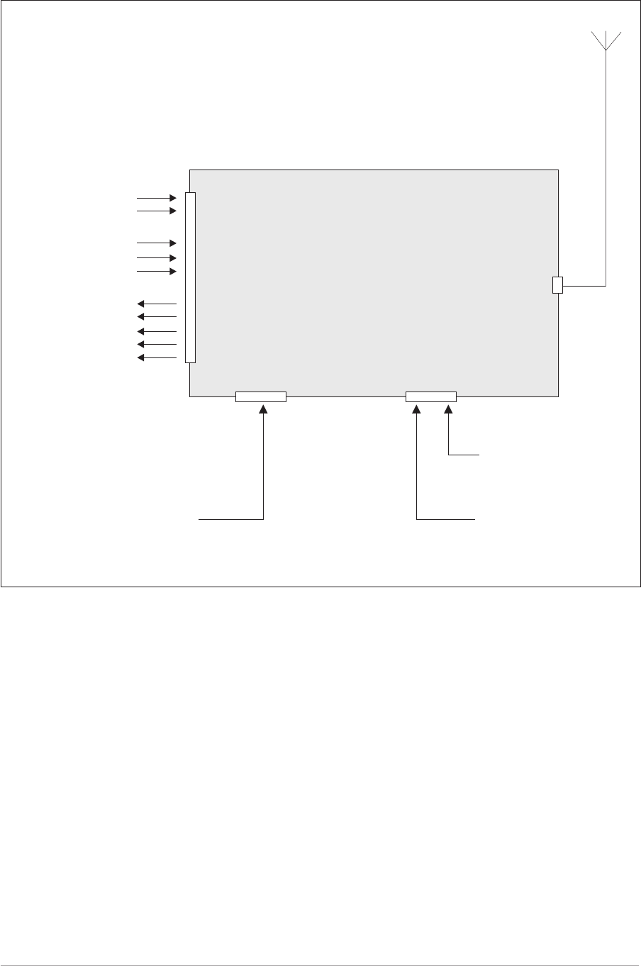
Fig. 2-1. T6T Transmitter - Basic Configuration
Audio
Remote PTT
External VSWR
Tx Inhibit
BIT Test
Antenna Changeover
PTT Status Signal
Unregulated Supply
Ready Signal
Tape Output
T6T Transmitter
Facilities
Connector Antenna
Connector
Microphone/Diagnostics
Connector
Reference
Connector
Remote Signals
Microphone/Headset
for Local Operation
PC for maintenance
purposes
Frequency Counter for
maintenance purposes
CONFIGURATION FOR OPERATION WITH MARC
When the T6T transmitter is used with a MARC system or other compatible control and data system, the
remote signals are connected through the rear panel MARC connector (see Fig. 2-2). In this
configuration, the rear panel Facilities and Computer Port connectors are not used unless some auxiliary
signals available at the Facilities connector are required.
Section 2 T6T AM-Voice Operation
Page 6
Fig. 2-2. T6T Transmitter - Configuration for Use with MARC
Microphone/Headset
for Engineering Use
PC for maintenance
purposes
Frequency Counter for
maintenance purposes
Audio
Remote PTT
Control Information
Status Information
Unregulated Supply
MARC
RSE 2
RSE 2
has 8
equipment
connectors
allowing up
to 8 radios
to be
connected
Equipment
Connector
T6T Transmitter
Antenna
Connector
Microphone/Diagnostics
Connector
Reference
Connector
MARC
Connector

Chapter 2. AM-Voice Specification
This chapter gives the transmitter's specification applicable to AM-voice operation.
RF CHARACTERISTICS
Channel spacing 25 kHz, or 8.33 kHz across the frequency band 118 to
136.975 MHz.
Spurious outputs Spurious outputs are below -46 dBm. Spurious outputs
are measured greater than 500 kHz from the carrier
frequency and with a modulation index below m = 0.9.
Transmitter rise time 90% of full power is reached within 20 ms of keying the
transmitter.
Transmitter decay time The output power decays by at least 20 dB 5 ms after
the keying potential is removed.
MODULATION CHARACTERISTICS
Modulation depth Adjustable up to 100%.
Hum and noise Greater than 45 dB below the signal level. Measured
within a 15 kHz bandwidth with the carrier modulated by
a 1 kHz signal and at a modulation depth of 90%.
Frequency response With 25 kHz channel spacing the variation in frequency
response, with reference to a 1 kHz signal, is within
+1 dB and -3 dB across the frequency range 300 Hz to
3.4 kHz. The response is better than -20 dB at 100 Hz,
and less than -30 dB at 5 kHz.
With 8.33 kHz channel spacing the variation in
frequency response, with reference to a 1 kHz signal, is
within +2 dB and -4 dB across the frequency range
350 Hz to 2.5 kHz. Frequencies above 3.2 kHz are
attenuated by at least 25 dB.
Distortion With a 90% modulation depth, distortion is less than 5%
at frequencies between 300 Hz and 3.4 kHz.
Residual FM With a 1 kHz signal set at 80% modulation applied to the
transmitter's audio input, the unwanted frequency
modulation is less than 500 Hz.
VOGAD The VOGAD has an operational range of 30 dB with the
threshold set relative to the line level setting. Within the
VOGAD range, the modulation depth is maintained
within 10% of the set level.
VOGAD has an attack time between 20 and 50 ms
measured with a 10 dB step to 15 dB into VOGAD, and
a decay time greater than 2 seconds.
T6T AM-Voice Operation Section 2
Page 7

Intentionally Blank
Section 2 T6T AM-Voice Operation
Page 8

Chapter 3. AM-Voice Installation
This chapter details the installation procedures that are applicable only to AM-voice operation.
WARNING. LETHAL VOLTAGES!
The instructions given in this chapter involve connecting lethal voltages to the
transmitter. The instructions detailed in this chapter must be carried out only by suitably
qualified personnel.
WARNING. ANTENNA RADIATION!
The antenna used with the transmitter must be installed such that the resultant radiated
field strength is below 10W/m² in areas normally accessible to personnel.
WARNING. BERYLLIUM/BERYLLIA!
The equipment covered by this handbook contains components containing the highly
toxic material Beryllium and/or its oxide Beryllia. These materials are particularly
hazardous if:
1. Beryllium materials are absorbed into body tissues through the skin, mouth,
or wound.
2. The dust created by breakage of Beryllia is inhaled.
3. Toxic fumes are inhaled from Beryllia/Beryllium involved in a fire.
The components containing Beryllia/Beryllium are: TR5, TR6 and TR9 in the
PA module.
WARNING. UNAUTHORIZED MODIFICATIONS!
Changes or modifications made to this equipment that are not expressly approved by
Park Air Electronics, or parties authorized by Park Air Electronics, could void the user’s
authority to operate the equipment.
CAUTION. ESSDs!
The T6T transmitter's circuitry contains Electrostatic Sensitive Devices (ESSDs).
Personnel must be aware of the precautions necessary to prevent damage to such
devices. During installation all precautions necessary to prevent ESSD damage must be
taken.
INTRODUCTION
The procedures in this chapter that allow a T6T transmitter to be installed for AM-voice operation are:
qSelecting the applicable keying method
qConnecting remote facilities.
T6T AM-Voice Operation Section 2
Page 9
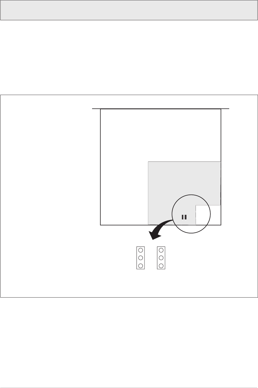
SELECTING THE APPLICABLE KEYING METHOD
The transmitter can be remotely keyed through the Facilities connector CN5 using either the Remote
PTT input, or by using Phantom Keying on the audio lines. The chosen method, and the required keying
potential is selected by the position of two jumpers (JP8 and JP9) fitted on the transmitter's DSP module.
To access the jumpers, remove the M3 captive screws that secure the transmitter's top cover (if not
already removed). Remove the cover and identify the links by referring to Fig. 2-3. Set the links to the
required positions as detailed under the next two headings: "Remote Keying" and "Phantom Keying".
When the jumpers have been configured, refit the transmitter's top cover.
Section 2 T6T AM-Voice Operation
Page 10
Fig. 2-3 Location of Jumpers JP8 and JP9
T6T Transmitter with top cover
removed showing position of
DSP module and jumpers JP8
and JP9
Front Panel
DSP Module
Phantom Keying
Remote Keying
28V
0V
JP8 JP9
Factory default setting. The transmitter is set for remote 0 volt keying unless specified
otherwise at the time of ordering.
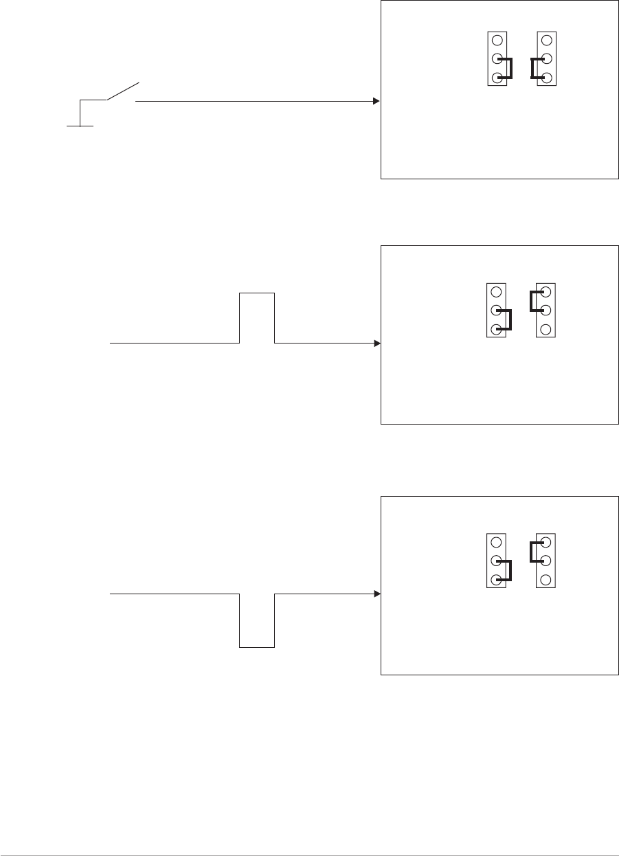
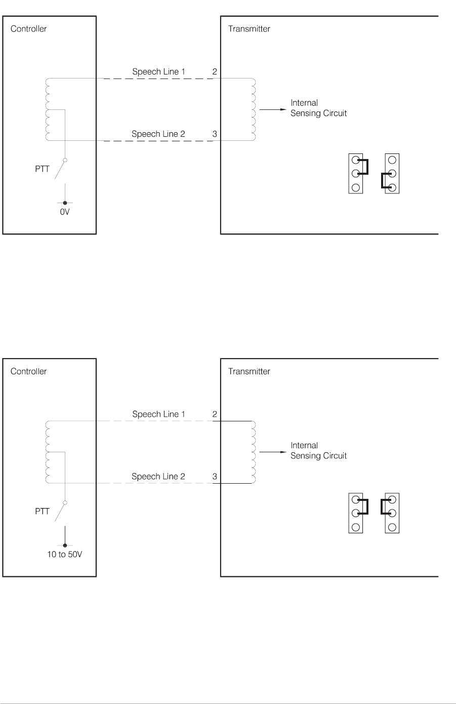
REMOTE KEYING CONFIGURATIONS
During installation jumpers JP8 and JP9 must be set to suit the remote keying potential. The keying
potentials are 0 volt, a dc voltage between +10 and +50 V, or a dc voltage between -10 and -50 V.
The following illustrations show the PTT signal, the settings of jumpers JP8 and JP9, and the ‘PTT in
polarity’ that must be set at the front panel when completing the ‘Operational Settings’ procedures.
T6T AM-Voice Operation Section 2
Page 11
Phantom Keying
Remote Keying
28V
0V
JP8 JP9
T6T Transmitter
[Front panel PTT Polarity = POS]
PTT Switch
0 volt
Remote PTT
0 Volt Keying
[Factory default setting]
+10 to +50 Volt Keying with Positive Going Active Signal
Phantom Keying
Remote Keying
28V
0V
JP8 JP9
T6T Transmitter
[Front panel PTT Polarity = POS]
+10 to +50 V
0V
PTT
Phantom Keying
Remote Keying
28V
0V
JP8 JP9
T6T Transmitter
[Front panel PTT Polarity = NEG]
PTT
+10 to +50 V
0V
+10 to +50 Volt Keying with Negative Going Active Signal
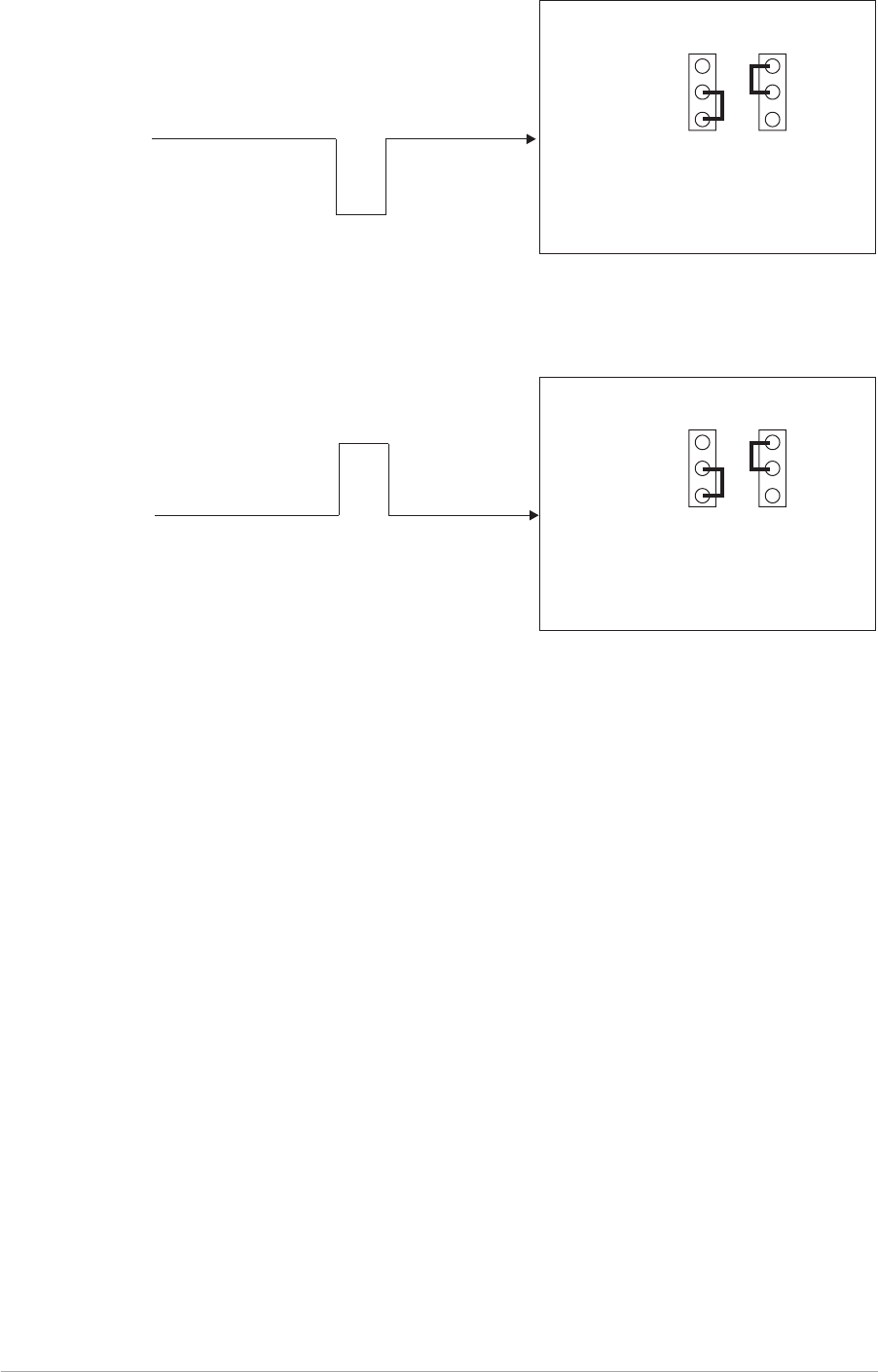
PHANTOM KEYING CONFIGURATIONS
Phantom keying can be used with the transmitter. This involves superimposing a dc potential on the
audio lines at the control equipment. The potential can be 0 volt, or between 10 and 50 volts as shown in
the illustrations on the opposite page.
To use phantom keying, the PTT switch at the control equipment must connect to a centre-tap on the
600 ohm audio transformer. The keying potential is connected to the centre-tap.
At the transmitter, jumpers JP8 and JP9, fitted to the DSP module, must be correctly set for phantom
keying.
Note that the audio lines in the illustrations connect to the transmitter's Facilities connector CN5. If
phantom keying is required when using a MARC, or compatible control and data system, the lines
connect to the MARC connector CN6 pins 2 and 3.
Section 2 T6T AM-Voice Operation
Page 12
Phantom Keying
Remote Keying
28V
0V
JP8 JP9
T6T Transmitter
[Front panel PTT Polarity = POS]
0V
-10 to -50 V
PTT
Phantom Keying
Remote Keying
28V
0V
JP8 JP9
T6T Transmitter
[Front panel PTT Polarity = NEG]
PTT
0V
-10 to -50 V
-10 to -50 Volt Keying with Negative Going Active Signal
-10 to -50 Volt Keying with Positive Going Active Signal
T6T AM-Voice Operation Section 2
Page 13
Fig. 2-4. Phantom Keying Arrangements
Phantom Keying
Remote Keying
28V
0V
JP8 JP9
Phantom Keying
Remote Keying
28V
0V
JP8 JP9
[Front panel PTT Polarity = POS]
[Front panel PTT Polarity = POS]

CONNECTING THE REMOTE FACILITIES
If the transmitter is being used in the ‘Basic Configuration’ (see Fig. 2-1 on page 5) remote signals are
terminated on the rear panel Facilities connector CN5. For configurations where the T6T transmitter is
being used with a MARC system, or other compatible data and control system, this procedure should be
ignored; instead, refer to ‘Connecting to MARC Equipment’.
The remote facilities available at CN5 are listed in section 1 on page 17. Essential connections, unless
the transmitter is being used only in local mode, are the audio input (pins 2 and 3) and a keying input. The
keying input can be the Remote PTT connection on pin 7, or Phantom Keying can be used on the audio
lines. The chosen method must correspond to the settings of internal jumpers JP8 and JP9 (see
page 10).
Make any other connections to CN5 as required.
When making connections to the Facilities connector CN5, and in order not to compromise the
transmitter's Electromagnetic Compatibility (EMC) users must:
qUse a D-type connector that has a screened cover
qUse screened multi-way cable, with the cable's screen connected to the Facilities connector's
shell or body.
Failure to comply with this instruction could result in non-compliance with
the European Commission EMC Directive 89/336/EEC
CONNECTING TO MARC EQUIPMENT
If the transmitter is being used with a MARC system, or compatible control and data system, remote
connections are made through the rear panel MARC connector CN6.
The pin-out of CN6 is shown in section 1 on page 18. If connecting to a MARC RSE 2 equipment, the
connections between CN6 and one of RSE 2's Equipment Connectors is pin-to-pin as shown in table 2-1.
When making connections to the Facilities connector CN6, and in order not to compromise the
transmitter's Electromagnetic Compatibility (EMC) users must:
qUse a D-type connector that has a screened cover
qUse screened multi-way cable, with the cable's screen connected to the Facilities connector's
shell or body.
Failure to comply with this instruction could result in non-compliance with
the European Commission EMC Directive 89/336/EEC
Section 2 T6T AM-Voice Operation
Page 14

Table 2-1 MARC Connector CN6 to RSE 2 Equipment Connector
T6T Transmitter RSE 2 Equipment Connector
Pin
Number Signal Name Pin
Number Signal Name
1 Ground 1 0 Volt
2 Line In (+) 2 Audio Line L1
3 Line In (-) 3 Audio Line L2
4 PTT 4 PTT
5 Unregulated Supply 5 Unregulated Supply Input
6 Data In (+) 6 Data Out (+)
7 Data In (-) 7 Data Out (-)
8 Data Out (+) 8 Data In (+)
9 Data Out (-) 9 Data In (-)
T6T AM-Voice Operation Section 2
Page 15

Intentionally Blank
Section 2 T6T AM-Voice Operation
Page 16
Chapter 4. AM-Voice Operational Settings
This chapter details how the T6T transmitter is set up for AM voice operation from the front panel.
It also details how to set the transmitter in and out of standby mode.
The transmitter can also be set up through a MARC system, or by using the VFP. Both of
these methods are outside the scope of this handbook; users should refer to the MARC
User Guide and the T6T Maintenance Handbook.
INTRODUCTION
Selecting most of the transmitter's operational settings is carried out using the front panel Scroll/Select
switch and the LCD (see the illustration below). Table 2-2 on page 19 shows a list of the operational
settings. No attempt to set up the transmitter should be made until the transmitter has been installed as
per the Installation Procedures given in section 1 of this user guide.
Normal Operation
During normal operation, the LCD displays the Main screen. This screen shows the operating frequency,
the channel number (if the channel store facility is used), the carrier offset (if used), and displays a
graphical representation of output power when the transmitter is keyed. If the transmitter has been set to
Standby mode, which is shown by the front panel STANDBY indicator being lit, the LCD is blanked.
Using the Scroll/Select Switch
The SCROLL/SELECT switch (referred to throughout this chapter as the ‘Switch’) is used to leave the
Main screen and display the Options menu. Further use of the Switch displays various selection menus
and allows the required parameters to be set. The switch has three actions: it can be turned clockwise,
anti-clockwise, or momentarily pushed in.
T6T AM-Voice Operation Section 2
Page 17
Freq 123.000MHz
Chan 1
Offset +5.0kHz
Pwr lllllllllll

SCREEN PROTOCOL
The following protocol is applicable to all screens described in this chapter.
Main Screen During normal transmitter operation, the Main screen, an example of which is
shown below, is displayed.
Freq 123 . 000MHz
Chan 1
Offset +5.0kHz
Pwr IIIIIIIIIIII
Switch Refers to the front panel Scroll/Select switch. The switch is turned clockwise to
scroll through fields from left to right, and from top to bottom. The switch is
turned anti-clockwise to scroll through fields from right to left, and from bottom
to top. The switch is pressed to make a selection.
Timeout If during any setting up procedure the Scroll/Select switch is not operated for
30 seconds, the display returns to the Main screen. If editing any parameter
has not been completed, the transmitter stays on the original setting.
>> Indicates more fields are available other than those currently displayed. To
access those fields, turn the switch clockwise through the last displayed field.
<< Indicates more fields are available other than those currently displayed. To
access those fields, turn the switch anti-clockwise through the first displayed
field.
Back When Back is selected, you are returned to the previous menu.
Exit When Exit is selected, you are returned to the Main screen.
Section 2 T6T AM-Voice Operation
Page 18

Table 2-2 Operational Settings
Parameter Adjustment Range Factory Default
Setting Further Reference
Menu Lock screen Locked or Unlocked Unlocked Page 20
To enter Standby mode On or Off Off Page 23
To exit Standby mode - - Page 24
Set mode of operation AM voice AM-voice
Part of AM Voice
Settings Procedure
starting on page 25.
PTT test facility On or Off Off
PTT timeout 2 s to 510 s, or off 180 s
Modulation depth 0 to 100% 85%
Tx mute On or off On
Vogad On or Off On
Carrier offset 0, ±2.5, ±4, ±5, ±7.3,
±7.5, or ±8 kHz 0 (no offset)
Adjust sidetone volume 0 to 100% 30%
Front panel frequency step size 8.33, 25 kHz, or both 25 kHz
LCD backlight timeout 15 s to 120 s, Off, or On 30 s
Part of General
Transmitter Settings
starting on page 29.
PTT inhibit On or Off Off
Line input level -40 dBm to 0 dBm -13 dBm
Output power 5 watt to 50 watt 50 W
MARC port baud rate 300 to 9600 baud 9600
PTT input signal polarity Positive or negative Pos
PTT output signal polarity Positive or negative Pos
Inhibit input signal polarity Positive or negative Pos
BIT initiate input signal polarity Positive or negative Pos
Ready output signal polarity Positive or negative Pos
Operating frequency 118 to 136.975 MHz 118.000 MHz Page 34
Store frequency channels 1 to 100 118.000 MHz Page 35
Recall frequency channels 1 to 100 - Page 36
Initiate a BIT test - - Page 37
View BIT pages and advise screen - - Page 38
Elapsed time indication - Page 39
Display internal reference
frequency screen - - Page 40
Software versions - Page 41
T6T AM-Voice Operation Section 2
Page 19

MENU LOCK SCREEN
A security facility available only from the VFP allows the transmitter's front panel to be ‘locked’. When this
facility is active, no operational settings can be made from the front panel until an ‘unlock’
command is sent from the VFP.
The following screen is displayed when ‘lock’ is active, and the front panel switch is pressed.
S ECUR I TY MESSAG E
SystemLocked
OK
To exit the system lock screen:
qTurn the switch to highlight OK, then press the switch. You are returned to the main screen.
or,
qWait for the 30 second timeout to expire. You are returned to the main screen.
Section 2 T6T AM-Voice Operation
Page 20

NOTES FOR SETTING UP THE TRANSMITTER
The following notes should be read before setting up the transmitter. They advise on the special
frequency display when using 8.33 kHz channel spacing, and give guidance on the optimum line level
setting.
Front Panel Display for 25 kHz and 8.33 kHz Channel Spacing
When setting the operating frequency of the transmitter and 8.33 kHz channel spacing is selected, the
displayed frequency differs from the actual channel frequency. Table 2-3 shows the pattern used for
25 kHz and 8.33 kHz spaced channel frequencies from 118.000 MHz to 118.1916 MHz. The pattern is
the same for any frequency within the transmitter's frequency range. The display conforms to ICAO
convention for 8.33 kHz operation.
Table 2-3 25 kHz and 8.33 kHz Channel Spacing Displays
Actual Frequency
(to 4 decimal places)
Channel
Spacing
Displayed Frequency
at Transmitter's Front Panel
118.0000 MHz
118.0000 MHz
118.0083 MHz
118.0166 MHz
118.0250 MHz
118.0250 MHz
118.0333 MHz
118.0416 MHz
118.0500 MHz
118.0500 MHz
118.0583 MHz
118.0666 MHz
118.0750 MHz
118.0750 MHz
118.0833 MHz
118.0916 MHz
118.1000 MHz
118.1000 MHz
118.1083 MHz
118.1166 MHz
118.1250 MHz
118.1250 MHz
118.1333 MHz
118.1416 MHz
118.1500 MHz
118.1500 MHz
118.1583 MHz
118.1666 MHz
118.1750 MHz
118.1750 MHz
118.1833 MHz
118.1916 MHz
25 kHz
8.33 kHz
8.33 kHz
8.33 kHz
25 kHz
8.33 kHz
8.33 kHz
8.33 kHz
25 kHz
8.33 kHz
8.33 kHz
8.33 kHz
25 kHz
8.33 kHz
8.33 kHz
8.33 kHz
25 kHz
8.33 kHz
8.33 kHz
8.33 kHz
25 kHz
8.33 kHz
8.33 kHz
8.33 kHz
25 kHz
8.33 kHz
8.33 kHz
8.33 kHz
25 kHz
8.33 kHz
8.33 kHz
8.33 kHz
118.000 MHz
118.005 MHz
118.010 MHz
118.015 MHz
118.025 MHz
118.030 MHz
118.035 MHz
118.040 MHz
118.050 MHz
118.055 MHz
118.060 MHz
118.065 MHz
118.075 MHz
118.080 MHz
118.085 MHz
118.090 MHz
118.100 MHz
118.105 MHz
118.110 MHz
118.115 MHz
118.125 MHz
118.130 MHz
118.135 MHz
118.140 MHz
118.150 MHz
118.155 MHz
118.160 MHz
118.165 MHz
118.175 MHz
118.180 MHz
118.185 MHz
118.190 MHz
T6T AM-Voice Operation Section 2
Page 21

Line Level
The line level, setting displayed on the front panel is equivalent to the average speech level with a
peak-to-average ratio of 13 dB. This corresponds to the level specified for the lines.
When testing the transmitter using a sine wave, the line input level should be set to 10 dB above the line
level setting.
The VOGAD and mute thresholds are preset at 10 dB and 15 dB respectively below the line level setting.
Table 2-4 Relationship between Line Level, Vogad, and Mute Threshold
Line Level
Setting
(dBm)
Average Speech
Level
(dBm)
Sine Wave Level
(dBm)
Vogad
Threshold Mute Threshold
0 0 +10 -10 -15
-5 -5 +5 -15 -20
-10 -10 0 -20 -25
-15 -15 -5 -25 -30
-20 -20 -10 -30 -35
-25 -25 -15 -35 -40
-30 -30 -20 -40 -45
-35 -35 -25 -45 -50
-40 -40 -30 -50 -55
Section 2 T6T AM-Voice Operation
Page 22

TO ENTER STANDBY MODE
Standby mode is a power saving feature that can be used for non-operational transmitters. When in
standby mode, most of the transmitter's circuits are inactive, the LCD is blanked, and the transmitter
cannot be keyed. To put the transmitter into standby mode, use the following procedure.
1. From the Main screen, press the switch to
display the Options menu. Ensure that
Configure is highlighted. Press the switch.
2. Ensure the Configure menu is displayed.
Turn the switch until Standby is highlighted,
then press the switch.
3. Check that the Standby menu is displayed.
Turn the switch until Yes is highlighted, then
press the switch. [To abandon this
procedure, select No instead of Yes and
then press the switch.]
4. Check that the LCD blanks, and the front panel STANDBY indicator lights.
5. The transmitter is now in standby mode. To exit standby, see the next procedure.
T6T AM-Voice Operation Section 2
Page 23
Frequency
Channe l
Con f i gu r e
BIT Exi t
Se t t i ngs
S/W Versions
St andby
Back Ex i t
Put radio into
St andby mode ?
YES NO

TO EXIT STANDBY MODE
Standby mode is indicated by the front panel STANDBY indicator being lit and the LCD being blanked.
To exit this mode, use the following procedure.
1. Press the switch and check that the Exit
menu is displayed.
2. Turn the switch until YES is highlighted, then press the switch. [To abandon this procedure,
select No instead of Yes and then press the switch.]
3. Check that the transmitter's Main screen is
displayed and that the front panel
STANDBY indicator is unlit.
4. The transmitter is now ready for normal use.
Section 2 T6T AM-Voice Operation
Page 24
Ex i t S t andby
Mod e
YES NO
Freq 123 . 000 MHz
Pw r

AM VOICE SETTINGS PROCEDURE
During this procedure, the following parameters, applicable to AM voice operation, will be set:
qMode of operation qPTT test facility
qPTT timeout qModulation depth
qMute enable or disable qVogad enable or disable
qSelecting a carrier offset qAdjusting the sidetone volume
qSelecting the channel spacing.
1. From the Main screen, press the switch to
display the Options menu. Turn the switch
until Configure is highlighted. Press the
switch.
2. Ensure the Configure menu is displayed.
Turn the switch until Settings is highlighted,
then press the switch.
3. Check that the Function menu is displayed.
Ensure Mode is highlighted. Press the
switch.
4. Setting the Mode of Operation.
Check that AM Voice is displayed. If any other mode is displayed, press the switch until AM Voice
is shown.
Turn the switch clockwise until Settings is
highlighted. Then press the switch to display
the mode specific Settings menu.
T6T AM-Voice Operation Section 2
Page 25
Frequency
Channe l
Con f i gu r e
BIT Exi t
Options Menu
Mod e
Reference Freq
Display
>>
Function Menu
Mod e : AM Vo i c e
Se t t i ngs
Cance l OK
Se t t i ngs
S/W Versions
St andby
Back Ex i t
Configure Menu

5. Setting the PTT Test Facility.
[Factory default setting: Off]
The PTT test facility can be set to Off or On.
When Off is selected, the transmitter is keyed only when the PTT signal is active.
When On is selected, the transmitter keys, and remains keyed until the display times out.
To set the PTT facility, ensure PTT is
highlighted. Press the switch to toggle
between Off and On. When the required
setting is displayed, turn the switch clockwise
to highlight PTT Timeout.
6. Setting the PTT Timeout.
[Factory default setting: 180 s]
The PTT timeout can be set to a value between 2 and 510 seconds (in two second steps), or it can
be set to Off. This setting affects the transmitter when keyed by a front panel microphone, or
through the remote lines.
To set the timeout ensure that PTT Timeout is
highlighted and press the switch. Turn the
switch clockwise to increment the time in
seconds, or anti-clockwise to decrement the
time in seconds. Note that the fully
anti-clockwise position switches the PTT
timeout to Off. When the required time, or Off,
is displayed press the switch. Turn the switch
clockwise to highlight Mod Depth.
7. Setting the Modulation Depth.
[Factory default setting: 85%]
The transmitter's modulation depth can be set
between 0 and 100% in increments of 1%.
To set the required value, ensure that Mod
Depth is highlighted and press the switch.
Turn the switch clockwise or anti-clockwise to
increment or decrement the value. When the
required value is displayed, press the switch.
Turn the switch clockwise until the next screen
is displayed and Mute is highlighted.
Section 2 T6T AM-Voice Operation
Page 26
PTT OFF
PTT T imeout 30s
Mod Depth 90%
>>
Mode Specific Settings Menu
PTT OFF
PTT T imeout 30s
Mod Depth 90%
>>
PTT OFF
PTT T imeout 30s
Mod Depth 90%
>>

8. Setting Mute On or Off.
[Factory default setting: On]
The transmitter's mute facility can be enabled or disabled.
To enable or disable the mute, ensure that
Mute Disable is highlighted. Press the switch
to toggle between On and Off. On = Mute
Disabled; Off = Mute enabled. When the
required setting is highlighted, turn the switch
clockwise to highlight Vogad.
9. Switching Vogad On or Off.
[Factory default setting: On]
The transmitter's Vogad facility can be set to On or Off.
To enable or disable the Vogad, ensure that
Vogad is highlighted. Press the switch to
toggle between On and Off. When the required
setting is highlighted, turn the switch clockwise
to highlight Offset.
10. Setting the Carrier Offset.
[Factory default setting: 0]
A carrier offset can be used with the transmitter. The available offsets are ±2.5 kHz, ±4.0 kHz,
±5 kHz, ±7.3 kHz, ±7.5 kHz, and ±8 kHz.
Note that transmitter type B6350OPT1 must be used if selecting an 8 kHz carrier offset, and a
separate setting up procedure must be completed. This procedure, which involves the use of
external test equipment, is detailed in the T6T transmitter maintenance handbook.
To select the required offset (0.0 kHz must be
selected if no offset is used) ensure that Offset
is highlighted and press the switch. Turn the
switch to display the required value, then press
the switch. Turn the switch clockwise, through
>> to highlight Headset.
T6T AM-Voice Operation Section 2
Page 27
Mu t e OFF
Vogad OFF
Offset 0.0kHz
<< >>
Mu t e OFF
Vogad OFF
Offset 0.0kHz
<< >>
Mu t e OFF
Vogad OFF
Offset 0.0kHz
<< >>

11. Adjusting the Sidetone Volume.
[Factory default setting: 30%]
The transmitter's sidetone volume through the
headset is adjusted from this screen. To do
this, ensure Headset is highlighted and press
the switch.
Check that the Volume setting is highlighted.
Turn the switch clockwise to increase volume,
or anti-clockwise to decrease volume. The
volume increments or decrements in 5%
steps. When the required setting is displayed,
press the switch. Highlight OK, and press the
switch to teurn to the mode specific settings
menu.
Turn the switch clockwise, through >> to highlight Channel Spacing.
12. Setting the Front Panel Frequency Step Size.
[Factory default setting: 25 kHz]
The transmitter's channel spacing can be 25 kHz, or 8.33 kHz. The radio automatically sets the
correct channel spacing for the frequency that is entered at the front panel. This setting, which is
only for the user's convenience, alters front panel frequency step size.
qIf all channels to be selected or stored are 25 kHz spaced channels, then 25 should be
selected.
qIf all channels to be selected or stored are 8.33 kHz spaced channels, then 8.3 should be
selected.
qIf a mixture of the two are required, both 25 and 8.3 should be selected.
To select the required spacing, ensure that
Channel Spacing is highlighted and press the
switch.
Check that the Channel Spacing menu is
displayed and that Spacing is highlighted.
Press the switch to change between 25 kHz,
8.3 kHz, and both. When the required value is
displayed, turn the switch to highlight OK, then
press the switch again. You will be returned to
the Mode Specific Settings menu.
13. To exit the AM Voice Settings Procedure, turn the switch to highlight OK, then press the switch.
You are returned to the Main screen. When this procedure is complete, go to the General
Transmitter Settings procedure starting on the next page.
Section 2 T6T AM-Voice Operation
Page 28
Spac ing 25kHz
Cance l OK
Headse t
Channe l Spac i ng
Back
Ex i t
Headse t
Channe l Spac i ng
Back
Ex i t
Volume 030%
OK

GENERAL TRANSMITTER SETTINGS
During this procedure the following parameters are set:
qSetting the LCD backlight qSetting inhibit to on or off
qSetting the input line level qSetting the output power
qSetting the MARC baud rate qSetting the PTT input signal polarity
qSetting the PTT output signal polarity qSetting the inhibit input signal polarity
qSetting the BIT initiate signal polarity qSetting the Ready output signal polarity
qSetting the antenna change-over signal
polarity
1. From the Main screen, press the switch to
display the Options menu. Turn the switch
until Configure is highlighted. Press the
switch.
2. Ensure the Configure menu is displayed.
Turn the switch until Settings is highlighted,
then press the switch to display the Function
menu.
3. Ensure the Function menu is displayed. Turn
the switch until Display is highlighted.
T6T AM-Voice Operation Section 2
Page 29
Frequency
Channe l
Con f i gu r e
BIT Exi t
Options Menu
Se t t i ngs
S/W Versions
St andby
Back Ex i t
Configure Menu
Mod e
Reference Freq
Display
>>
Function Menu

4. Setting the LCD Backlight.
[Factory default setting: 30 s]
The LCD's backlight can be set to off,
permanently on, or timed to stay on for a
period between 15 and 120 seconds
(adjustable in 15 second steps) after the
Scroll/Select switch was last operated.
Check that the Function menu is displayed
and ensure Display is highlighted. Press the
switch.
Ensure the Backlight menu is displayed and
the Backlight setting is highlighted. Rotation
of the switch displays the full range of
settings. When the required setting is
highlighted, press the switch. Turn the switch
until OK is highlighted, then press the switch.
You are returned to the Function menu.
5. Setting Inhibit.
[Factory default setting: Off]
Inhibit can be set to either On or Off. When set to on, the transmitter cannot be keyed; when set to
off the transmitter operates normally. Note that a separate Inhibit function is available on the
Facilities connector CN5 (see pin-out in section 1 on page 17).
From the Function menu, turn the switch
clockwise until Inhibit is highlighted, then
press the switch.
Check that the Inhibit menu is displayed and
Inhibit is highlighted. Pressing the switch
toggles between On and Off. When the correct
setting is displayed turn the switch clockwise
to highlight OK, then press the switch. You are
returned to the Function menu.
Section 2 T6T AM-Voice Operation
Page 30
Mod e
Reference Freq
Display
>>
Back l i gh t OFF
Cance l OK
Inhibi t
Line Level
Powe r
<< >>
Inhibi t ON
Cance l OK

6. Setting the Line Level.
[Factory default setting: -13 dBm]
The audio line level can be set to any value between -40 dBm and 0 dBm. Some notes regarding
the optimum line level are given on page 22.
From the Function menu, turn the switch
clockwise until Line Level is highlighted, then
press the switch.
Check that the Line Level menu is displayed
and that Line Lvl is highlighted, then press the
switch.
Turn the switch clockwise or anti-clockwise to
increase or decrease the value. When the
required value is displayed, press the switch.
Turn the switch to highlight OK and then press
the switch. You are returned to the Function
menu.
7. Setting the Output Power.
[Factory default setting: 50 W]
The transmitter's output power can be set to any value between 5 watts and 50 watts (in one watt
steps).
From the Function menu, turn the switch
clockwise until Power is highlighted, then
press the switch.
Ensure that the Power menu is displayed and
that Power is highlighted.
Press the switch. Turn the switch clockwise to
increase the power, or anti-clockwise to
decrease the power. When the required value
is displayed, press the switch. Turn the switch
clockwise until OK is highlighted, then press
the switch. You are returned to the Function
menu.
T6T AM-Voice Operation Section 2
Page 31
Inhibi t
Line Level
Powe r
<< >>
Line Lvl -13dBm
Cance l OK
Inhibi t
Line Level
Powe r
<< >>
Powe r 50W
Cance l OK

8. Setting the MARC Baud Rate.
[Factory default setting: 9600]
The baud rate must be set when the T6T transmitter is connected to a MARC system (or other
compatible data and control system). The rate can be set to 300, 600, 1200, 2400, 4800, or 9600
baud. The standard setting for MARC systems is 9600 baud.
From the Function menu, turn the switch
clockwise until MARC is highlighted, then
press the switch.
Ensure that the MARC menu is displayed and
that the Baud Rate is highlighted. Press the
switch.
Turn the switch until the required value is
displayed, then press the switch. Turn the
switch clockwise until OK is highlighted, then
press the switch. You are returned to the
Function menu.
9. Polarity Settings.
The polarity of the following input and output and output signals is set using the Polarity menu:
qPTT input signal
qPTT output signal
qInhibit input signal
qBIT initiate input signal
qReady output signal.
In addition to the signals listed, the polarity of
the Antenna Change-Over signal is
determined from this menu. It is always the
same polarity as the PTT output signal.
To establish the required polarity for the PTT
input signal, refer to the illustrations starting on
page 11 under the heading ‘Remote Keying Configurations’. Note that internal links must also be
correctly configured to obtain the required input PTT configuration.
To establish the required polarity for the other input and output signals, refer to table 2-5.
To set the required polarity, turn the switch to highlight the required parameter, then press the
switch to toggle between NEG and POS.
Section 2 T6T AM-Voice Operation
Page 32
MARC
Po l a r i t y
Back
Ex i t <<
Baud Rate 9600
Cance l OK
PTT I n NEG
PTT Ou t POS
Inhibi t NEG
>>
BIT Ini t NEG
Ready Out POS
Back
Ex i t <<
Polarity Menu

Table 2-5 Signal Polarities
Signal Description State when Polarity is
set to NEG
State when Polarity is
set to POS
PTT output
This output, when active,
indicates the transmitter is
keyed. It is a grounding
output.
Output is a high
impedance when the
transmitter is keyed, and
0 volt when not keyed.
Output is 0 volt when the
transmitter is keyed, and a
high impedance when not
keyed.
Transmitter
inhibit
This input signal, when
active, prevents the radio
from being keyed. This is
a TTL input pulled-up to
5V.
A 5 volt input inhibits the
transmitter.
A 0 volt input inhibits the
transmitter.
BIT initiate
An input signal that
initiates a BIT interruptive
test. This is a TTL input
pulled-up to 5 V. The input
signal must be active for a
minimum of 300 ms; the
signal cannot then be
activated again for at least
3 seconds.
A 5 volt input initiates a
BIT test.
A 0 volt input initiates a
BIT test.
Ready output
This output is active when
the radio is ready to
transmit and no faults
have been detected by the
BIT circuitry. It is an open
collector output.
Output is a high
impedance when the
transmitter is ‘ready’, and
0 volt when not ‘ready’.
Output is 0 volt when the
transmitter is ‘ready’, and
a high impedance when
not ‘ready’.
Antenna
change-over
An output signal that can be used to control an antenna change-over relay when the
transmitter is used in conjunction with a T6R receiver. Antenna change-over is a
grounding output.
This signal cannot be independently set. It is always the same polarity as the PTT
output signal.
10. To exit the General Transmitter Settings Procedure, turn the switch to highlight Exit, then press
the switch. You are returned to the Main screen. When this procedure is complete, go to Setting
the Operating procedure starting on the next page.
T6T AM-Voice Operation Section 2
Page 33

SETTING THE OPERATING FREQUENCY
To set the transmitter's operating frequency, use the following procedure. If a frequency is to be stored
as one of the 100 available preset channels, ignore this procedure and go to ‘Allocating Channel
Numbers to Specified Frequencies’ on page 35. Before setting the operating frequency, the required
channel spacing should be set (see page 28).
1. From the Main screen, press the switch to
display the Options menu. Ensure that
Frequency is highlighted. Press the switch.
2. Ensure the Set Frequency menu is
displayed and that the MHz digits are
highlighted. Press the switch.
3. Turn the switch clockwise to increase frequency, or anti-clockwise to decrease frequency. The
MHz value increments/decrements in 1 MHz steps. Stop when the required value is shown. Press
the switch.
4. Turn the switch clockwise to highlight the kHz digits and press the switch. Turn the switch
clockwise to increase frequency, or anti-clockwise to decrease frequency (note that continuous
scrolling of the kHz value will increment or decrement the MHz value). Stop when the required
value is shown. Press the switch. Note that if 25 kHz channel spacing is selected, the kHz value
increments/decrements in 25 kHz steps; if 8.33 kHz channel spacing is selected, the kHz value
increments/decrements in the pattern detailed in ‘table 2-3, Front Panel Display for 25 kHz and
8.33 kHz Channel Spacings’ on page 21. If both is selected, the display shows the 25 kHz and
8.33 kHz channels.
5. Turn the switch clockwise until either Cancel or OK is highlighted. Then press the switch. If cancel
is selected, the new frequency entered in this procedure is ignored. If OK is selected, the
transmitter operates on the new frequency.
Section 2 T6T AM-Voice Operation
Page 34
Frequency
Channe l
Con f i gu r e
BIT Exi t
121 . 500MHz
Cance l OK

ALLOCATING CHANNEL NUMBERS TO SPECIFIED FREQUENCIES
Up to 100 frequency channels can be stored in the transmitter. Use the following procedure to allocate
frequency channels.
1. From the Main screen, press the switch to
display the Options menu. Turn the switch
until Channel is highlighted. Press the
switch.
2. Ensure the Channel menu is displayed. Turn
the switch until Set is highlighted. Press the
switch.
3. Ensure the Channel screen is displayed and
turn the switch until the channel number is
highlighted. Press the switch, then turn the
switch until the required channel number is
displayed. When it is, press the switch.
4. Turn the switch to highlight the MHz value, then press the switch. Turn the switch until the
required value is displayed, then press the switch. Repeat for the kHz value.
5. When the correct frequency for the
displayed channel number is displayed, turn
the switch until Store is highlighted, then
press the switch.
6. Repeat steps 3 to 5 for all frequency channels that are to be stored. When the required number of
frequency channels have been stored, highlight Store and End and press the switch. You will be
returned to the Main screen.
T6T AM-Voice Operation Section 2
Page 35
Ch001 119 . 100MHz
Reca l l
Store
Store and End
Ch001 119 . 100MHz
Reca l l
Store
Store and End
Ch007 123 . 450MHz
Reca l l
Se t
Back
Frequency
Channe l
Con f i gu r e
BIT Exi t
The process of allocating frequency channels can be simplified by using the VFP.
The VFP software is contained in the T6T transmitter's maintenance kit.

TO RECALL CHANNEL FREQUENCIES
Frequency channels that have been stored in the transmitter can be recalled by channel number as
follows.
1. From the Main screen, press the switch to
display the Options menu. Turn the switch
until Channel is highlighted. Press the
switch.
2. Ensure the Channel menu is displayed. Turn
the switch until the channel number is
highlighted. Press the switch. Turn the
switch until the required channel number is
displayed. Then press the switch.
3. Turn the switch until Recall is highlighted,
then press the switch.
4. The Main screen will then be displayed
showing the transmitter's selected channel
number and corresponding operating
frequency.
Section 2 T6T AM-Voice Operation
Page 36
Frequency
Channe l
Con f i gu r e
BIT Exi t
Ch007 123 . 450MHz
Reca l l
Se t
Back
Ch007 123 . 450MHz
Reca l l
Se t
Back
Freq 123 . 450MHz
Chan 7
Pw r

TO INITIATE AN INTERRUPTIVE BIT TEST
Use the following procedure to initiate an interruptive BIT test from the transmitter's front panel. A BIT
test cannot be initiated while the transmitter is keyed.
1. From the Main screen, press the switch to
display the Options menu. Turn the switch
until BIT is highlighted. Press the switch.
2. Ensure the BIT menu is displayed. Turn the
switch until BIT Initiate is highlighted, then
press the switch.
3. During the test, which takes approximately
two seconds, the Testing screen is
displayed.
4. When the test has finished, check that the transmitter's front panel Alarm indicator is not lit. After a
BIT test, BIT screens are automatically displayed. The screens are shown on the next page.
T6T AM-Voice Operation Section 2
Page 37
Frequency
Channe l
Con f i gu r e
BIT Exi t
BIT Ini t iate
BIT View
Back Ex i t
Test ing
Pl ease Wa i t
During an interruptive BIT test, the transmitter radiates a modulated carrier wave. Users
should therefore obtain the necessary authority before initiating a test.
Users should ensure a load is connected to the transmitter's antenna connector,
and note that the BIT circuits apply a signal to the audio input lines during a test.

TO VIEW BIT PAGES AND ADVISE SCREEN
Use the following procedure to view the BIT page displays. Note that after a BIT interruptive test, the BIT
screens are automatically displayed.
1. From the Main screen, press the switch to
display the Options menu. Turn the switch
until BIT is highlighted. Press the switch.
2. Ensure the BIT menu is displayed. Turn the
switch until BIT View is highlighted, then
press the switch.
3. A series of pages is shown displaying
certain transmitter parameters. Some
examples are shown here.
A full list of BIT screens along with
appropriate explanations is given in the
T6T transmitter maintenance handbook.
4. Note that the last BIT screen allows Advise
to be highlighted and selected by pressing
the switch. If any BIT faults have been
detected, the advise screen recommends
the remedial action, in order of priority, to be
taken.
Further detail regarding the Advise screen
is given in the T6T transmitter maintenance
handbook.
Section 2 T6T AM-Voice Operation
Page 38
Frequency
Channe l
Con f i gu r e
BIT Exi t
BIT Ini t iate
BIT View
Back Ex i t
AC Supp l y ON
DC Supp l y OFF
Supp l y 31V
>>
Example BIT Screen
Syn t h Lock PASS
PA T emp 3 0 °
PA Temp PASS
<< >>
Example BIT Screen
Advise
Back
<<
Last BIT Screen
Pl ease Check
1:Antenna
2:PA Ctrl .
Example Remedial Advise Screen

ELAPSED TIME INDICATOR
An elapsed time indicator (ETI) shows the number of hours the transmitter has been powered up since
manufacture. To view the ETI:
1. From the Main screen, press the switch to
display the Options menu. Turn the switch
until BIT is highlighted. Press the switch.
2. ETI can be seen measured in hours and
minutes.
T6T AM-Voice Operation Section 2
Page 39
Frequency
Channe l
Con f i gu r e
BIT Exi t
BIT Ini t iate
BIT View
ETI 00123:59
Back Ex i t

DISPLAYING THE TRANSMITTER'S INTERNAL REFERENCE FREQUENCY SCREEN
To display the transmitter's internal reference frequency screen, use the following procedure.
1. From the Main screen, press the switch to
display the Options menu. Turn the switch
until Configure is highlighted. Press the
switch.
2. Ensure the Configure menu is displayed.
Turn the switch until Settings is highlighted,
then press the switch.
3. Check that the Function menu is displayed
and turn the switch until Reference Freq is
highlighted. Press the switch.
4. Ensure the Reference menu is displayed.
5. To exit the screen, wait for 30 seconds when
the display automatically reverts to the Main
screen, or select Cancel.
Section 2 T6T AM-Voice Operation
Page 40
Frequency
Channe l
Con f i gu r e
BIT Exi t
Se t t i ngs
S/W Versions
St andby
Back Ex i t
Mod e
Reference Freq
Display
>>
Ref Freq 50.0%
Cance l OK
Caution!
This procedure is included only for informational purposes. The reference frequency setting
must not be altered unless following the procedure given in the T6T maintenance handbook.
External test equipment is required to set this parameter.
Failure to comply with this caution may render the transmitter inoperable.

SOFTWARE VERSIONS SCREEN
The software versions screen allows the user to view the version of various software modules installed in
the transmitter. To view the software versions, use the following procedure.
1. From the Main screen, press the switch to
display the Options menu. Ensure that
Configure is highlighted. Press the switch.
2. Ensure the Configure menu is displayed.
Turn the switch until S/W Versions is
highlighted, then press the switch.
3. Check the Software Versions screen is
displayed. Select Boot, Flash, or Fills and
press the switch to display the installed
version. The example shows the Boot
software.
4. Select OK, then press the switch to return to
the Software Versions screen. View the
other software modules as required.
T6T AM-Voice Operation Section 2
Page 41
Frequency
Channe l
Con f i gu r e
BIT Exi t
Options Menu
Se t t i ngs
S/W Versions
St andby
Back Ex i t
Configure Menu
Boo t
Flash
Fills
Back Ex i t
Software Versions Screen
Boot Version
S0271V0001
OK
Boot Version Screen