Park Air Systems B6350-S2 VHF ground to air transmitter User Manual v6 T6T T6R 4pp datasheet
Park Air Systems Limited VHF ground to air transmitter v6 T6T T6R 4pp datasheet
Contents
- 1. User guide
- 2. Brochure
Brochure

PAE
T6 Series
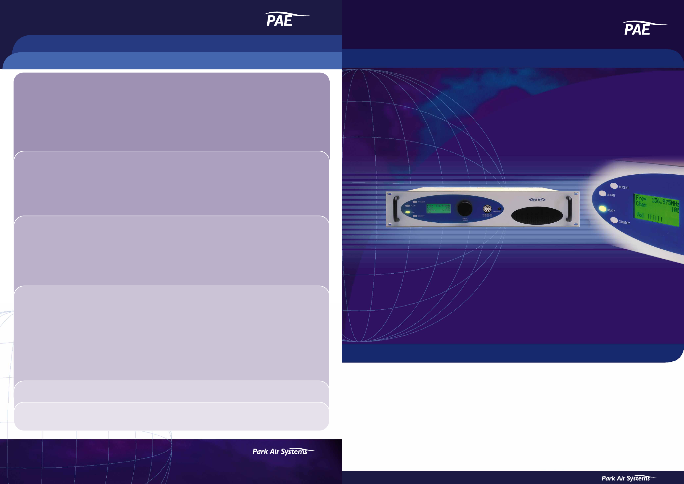
PAE T6T TRANSMITTER and T6R RECEIVER, VHF Multimode Digital Radio (MDR)
•VHF 118 to 137 MHz Multimode Digital Radio (MDR)
•8.33 kHz and 25 kHz channel spacing
•50 W RF transmit output power
•Digital Coherent Mute (DCM) technology
•Five-offset carrier capability
•Analogue and digital operation
•Extensive remote control facilities
TECHNICAL INFORMATION
PAE T6T TRANSMITTER and T6R RECEIVER, VHF Multimode Digital Radio (MDR)
A subsidiary of Northrop Grumman Corporation
Park Air Systems Ltd, Northfields, Market Deeping, Peterborough, England, PE6 8UE
Tel: +44 1778 345434 Fax: +44 1778 342877 Email: sales@parkairsystems.com
www.parkairsystems.com
The PAE T6T Transmitter and T6R Receiver
for advanced airspace communications
GENERAL - T6T and T6R
Frequency range 118 to 136.975 MHz
Channel spacing:
AM-voice 8.33 kHz and 25 kHz
AM data 25 kHz
Modes: A3E AM-voice
Options AM-MSK
VDL-2
VDL-3
Mode memory slots 4
Supported standards ICAO Annex 10
EN 301 841-1
EN 300 676
Frequency stability: <1 ppm
Option 1 <0.3 ppm (T6T only)
Ref oscillator adjust From front panel rotary encoder
Duty cycle 100% continuous transmit
Operating temperature -20 to +55˚C
Storage temperature -30 to +70˚C
Power consumption: ac dc
T6T - transmit 330 VA 10 A
T6T - standby 20 VA 0.4 A
T6R - receive 35 VA 1 A
T6R - standby 20 VA 0.4 A
Supplies:
ac T6T: 110/120/220/230/240 V (±10%)
48 to 62 Hz
T6R: 99 to 264 V 48 to 62 Hz
dc 21.6 to 32 V
CONTROL - T6T and T6R
Full control and monitoring of the T6T and T6R can be carried out
locally using the front panel controls and display, from a computer
connected to the front panel, or remotely via a RS422 serial port
from PAE MARC or similar.
Pre-set channels 100
Channel settings Frequency, channel spacing, memory
assignment, frequency offset
Front panel lock out Prevents unauthorised adjustment
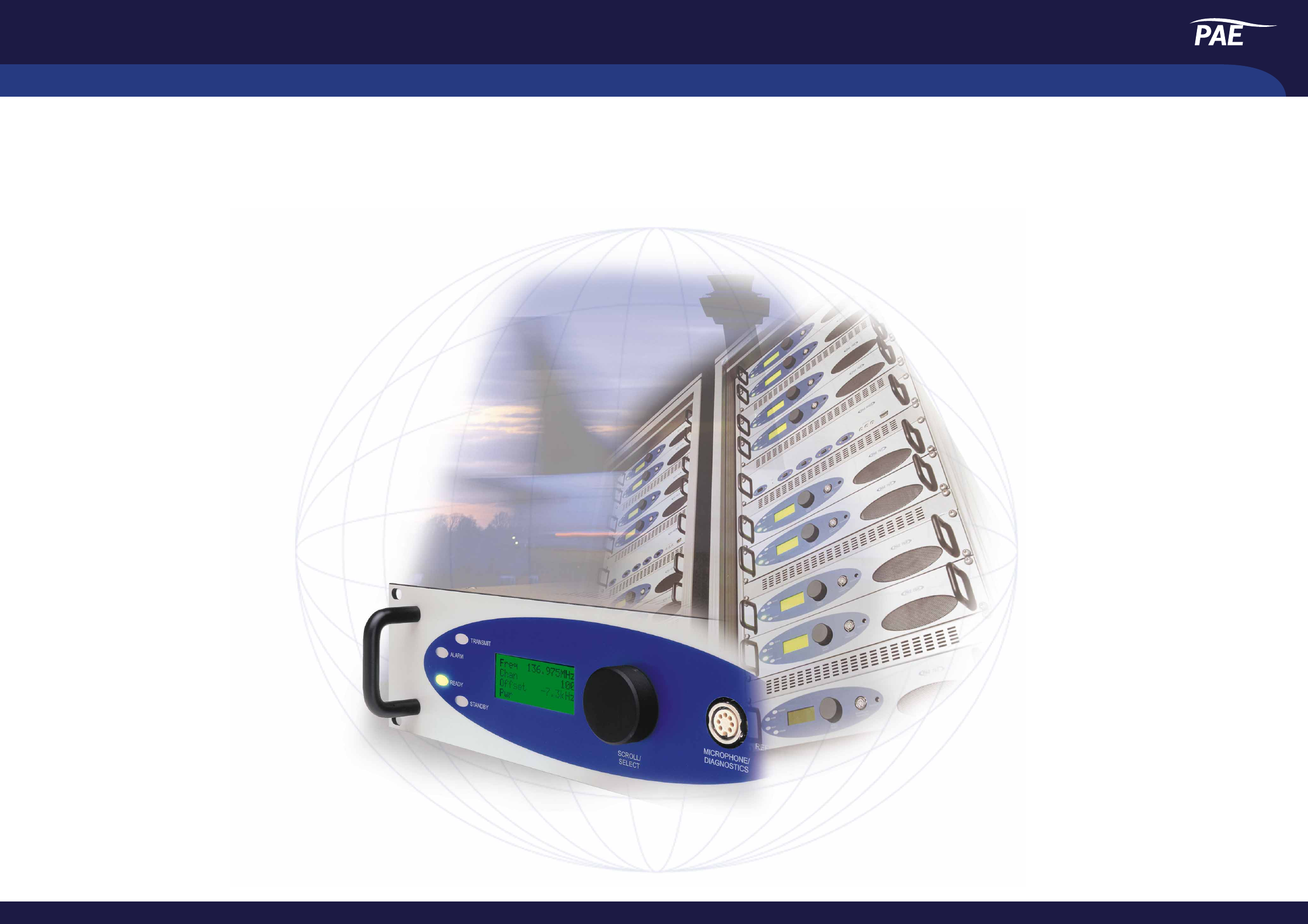
Local control facilities Rotary encoder and backlit multifunction
display provide menu driven control of all
radio operating parameters and BIT functions
LED indicators for standby, ready,
alarm, receive (on T6R) and transmit (on T6T)
Mic/headset/diagnostic port for local
operation and programming from
computer via RS232 serial link
Coaxial connector for monitoring
reference oscillator frequency
Remote control ports:
Facilities Audio and control for AM operation
MARC RS422 serial port for control of radio
from MARC or other compatible system
HDLC Serial interface for VDL operation
TRANSMIT - T6T
Carrier power 5 to 50 W in 1 W steps
Modulation 0 to 100% in 1% steps
VSWR mismatch Full power into VSWR of 2.5:1
Infinite VSWR without damage
Offset carrier:
2-offset carrier ±5 kHz
3-offset carrier fc and ±7.3 kHz
4-offset carrier ±2.5 kHz and ±7.5 kHz
5-offset carrier fc, ±4 kHz and ±8 kHz (Option 1 only)
Oscillator detect Monitors installed oscillator. Inhibits offset
programming if invalid oscillator fitted
Harmonic outputs <-36 dBm
Spurious outputs <-46 dBm
VOGAD <10% change in modulation depth for
30 dB change in input level
Tx mute 5 dB below VOGAD threshold
Time out Off, or 2 s to 510 s in 2 s steps
Audio distortion <5% THD
Audio bandwidth:
8.33 kHz 350 Hz to 2500 Hz
25 kHz 300 Hz to 3400 Hz
Audio interface:
Line input -40 dBm to 0 dBm in 1 dB steps
Tape output -10 dBm
RECEIVE - T6R
Sensitivity -107 dBm for 10 dB (S+N)/N
Selectivity:
8.33 kHz <6 dB at ±3.5 kHz
>70 dB at ±8.33 kHz
>80 dB at ±25 kHz
25 kHz <6 dB at ±11 kHz
>80 dB at ±25 kHz
Squelch Threshold adjustable in 1 dB steps for
RF input levels from -114 dBm to
-60 dBm [equivalent to <6 to >30 dB
(S+N)/N]. Incorporates Digital Coherent
Mute (DCM) technology to dynamically
filter on-channel interference. DCM
automatically mitigates co-location
interference to ensure the squelch opens
whenever an input signal exceeds the set
threshold and has a positive (S+N)/N ratio
AGC RF <3 dB change in audio output for RF
signals between -107 dBm and +10 dBm
AGC audio <1 dB change in audio output for
modulation depth change between
90% and 30%. Automatically maintains
audio at the 90% modulation equivalent
level for maximum fidelity
Antenna radiation <-73 dBm
Audio distortion <5% THD
Audio bandwidth:
8.33 kHz 350 Hz to 2500 Hz
25 kHz 300 Hz to 3400 Hz
Audio interface:
Line output -30 dBm to +10 dBm in 1 dB steps
Loudspeaker 1 W
Tape output -10 dBm
MECHANICAL - T6T and T6R
Dimensions T6T: 89(H) x 483(W) x 450(D) mm
T6R: 89(H) x 483(W) x 430(D) mm
Weight T6T: 17 kg
T6R: 6 kg
RF connectors N-type socket
ORDERING INFORMATION - T6T and T6R
T6T transmitter: Part No. B6350
Option 1 (high stab oscillator) Part No. B6350OPT1
T6R receiver Part No. B6100
T6T transmitter user guide Part No. 31-360000TX
T6R receiver user guide Part No. 31-360000RX
Microphone Part No. 24-11030301
Headset Part No. 24-12002801
End-fed dipole antenna Part No. B2080
Park Air Systems reserves the right to amend specifications in the light of continuing development - 012-1

PAE T6T TRANSMITTER and T6R RECEIVER, VHF Multimode Digital Radio (MDR)
PAE T6 Series
The PAE T6T Transmitter and T6R Receiver
for advanced airspace communications
The PAE T6T and T6R multimode digital
radios are designed to provide ground-to-air
communications for professional applications
in airport and en route centres. The radios
will support both voice and ICAO defined
data modes.
The T6 series incorporates 8.33 kHz and
25 kHz channel spacing. The radios recognize
frequencies entered in ICAO format and
automatically adjust to the correct channel
spacing. For multichannel operation, any
combination of 8.33 kHz and 25 kHz channel
spacing can be programmed. A 100 channel
memory allows immediate recall of stored
frequencies. Front panel operation can be
‘locked’ to prevent unauthorised adjustment
of radio parameters.
The T6T supports ICAO defined offset carrier
operation. The standard master oscillator
supports two, three and four-offset carrier
operation, the optional high stability oscillator
also allows five-offset carrier operation. The
radio detects the oscillator fitted and will inhibit
five-offset carrier operation if the high stability
option is not detected.
Careful implementation of DSP techniques
significantly reduces the component count within
the radios. This leads to increased reliability and
reduced logistic costs. All modulation and
demodulation processes are carried out using
DSP algorithms that provide consistent long-term
performance to further enhance equipment
reliability. All adjustable parameters within the
radios can be modified using the front panel
controls, or from a computer connected to the
headset/diagnostics port, eliminating the need to
remove equipment covers during the operational
life of the radio.
The radios can be operated locally using the front
panel controls, or remotely via flexible control
interfaces. STANDBY mode allows the radios to be
powered on and off remotely to ensure minimal
current drain on local power supplies.
The use of innovative RF engineering allied
to sophisticated DSP technology provides
class leading performance. The advanced
design of the T6 series transmitter and receiver
allows operation in demanding co-site conditions,
reducing the need for external filters. The T6T
transmitter employs a sophisticated feedback
technique that minimizes spectral noise and
enhances signal purity. The power amplifier is
designed for optimum performance and maximum
reliability and will support continuous operation
applications.
The T6R receiver circuitry benefits from
unique DSP implemented Digital Coherent
Mute (DCM) technology. DCM uses specially
developed algorithms that monitor on-channel
activity and dynamically filter unwanted interfering
signals. The receiver front-end has exceptional
signal handling properties that ensure rejection
of unwanted off-channel signals while maintaining
excellent low level wanted signal performance.
Comprehensive Built-In Test (BIT) monitors
both static and dynamic parameters. Results
can be viewed on the front panel LCD and
summarized via READY and ALARM indicators. All
BIT data is available for remote monitoring via serial
ports, and transmitters and receivers can be readily
networked for remote monitoring using the PAE
Multi-Access Remote Control (MARC) or similar
systems.