Park Air Systems B6550-S2 VHF ground to air transceiver User Manual t6tr
Park Air Systems Limited VHF ground to air transceiver t6tr
UserManual.wiki
>
Park Air Systems
>
B6550-S2 User Manual
>
User guide
Contents
1.
User guide
2.
Brochure
User guide
Navigation menu
Upload a User Manual
Namespaces
Wiki Guide
HTML
PDF
Info
Views
User Manual
Discussion / Help
Navigation
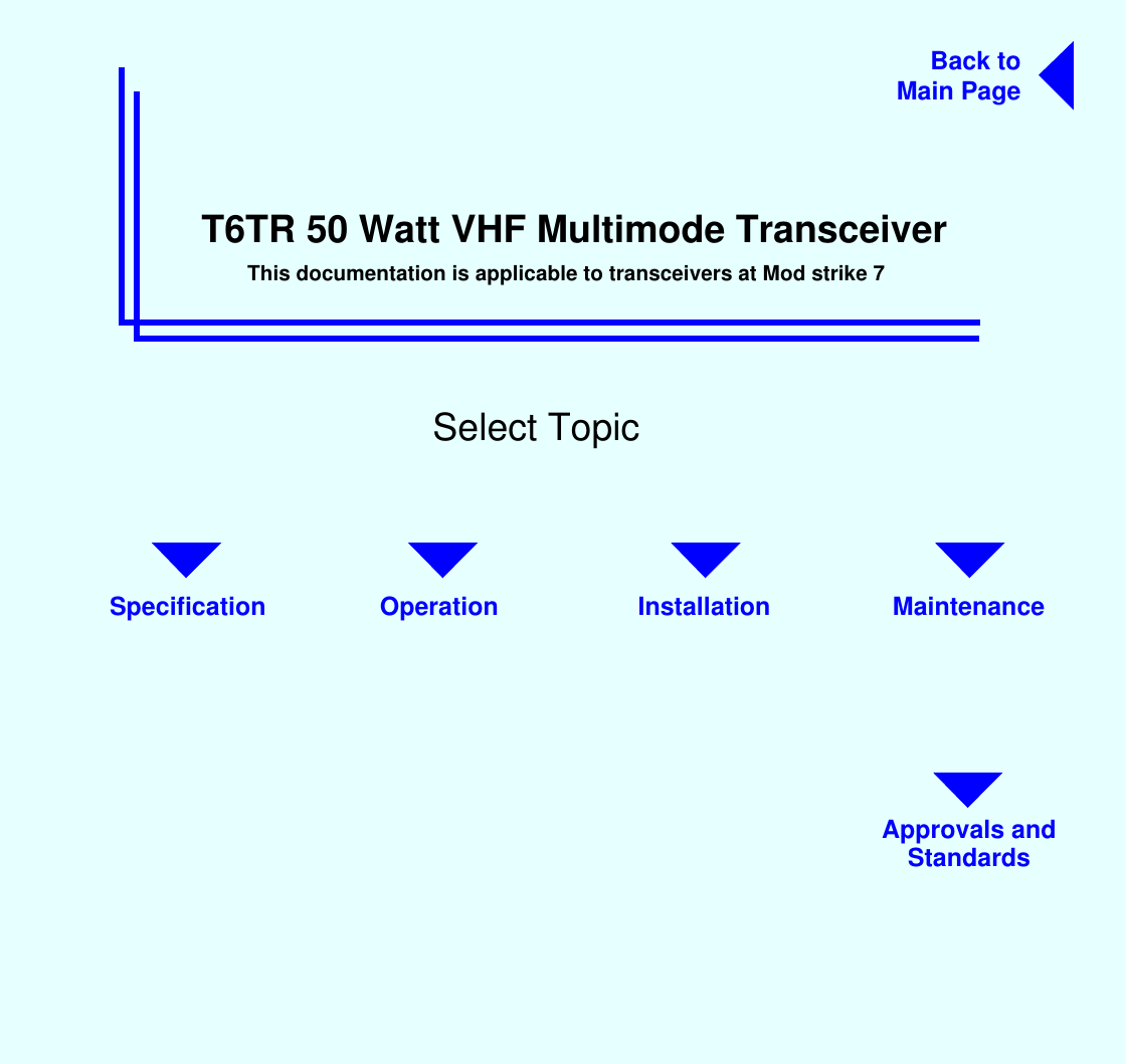
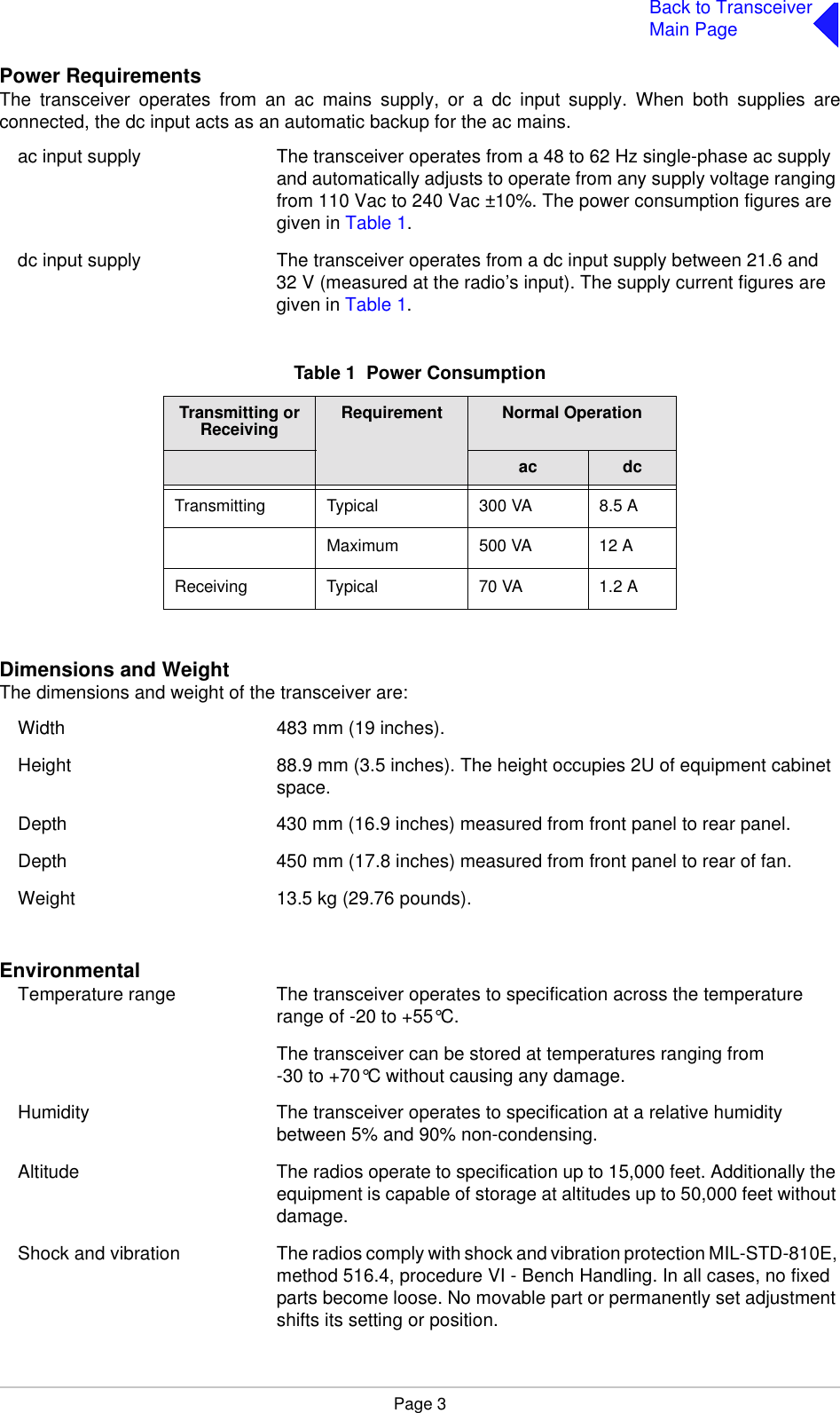
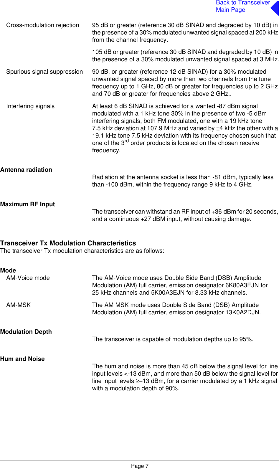
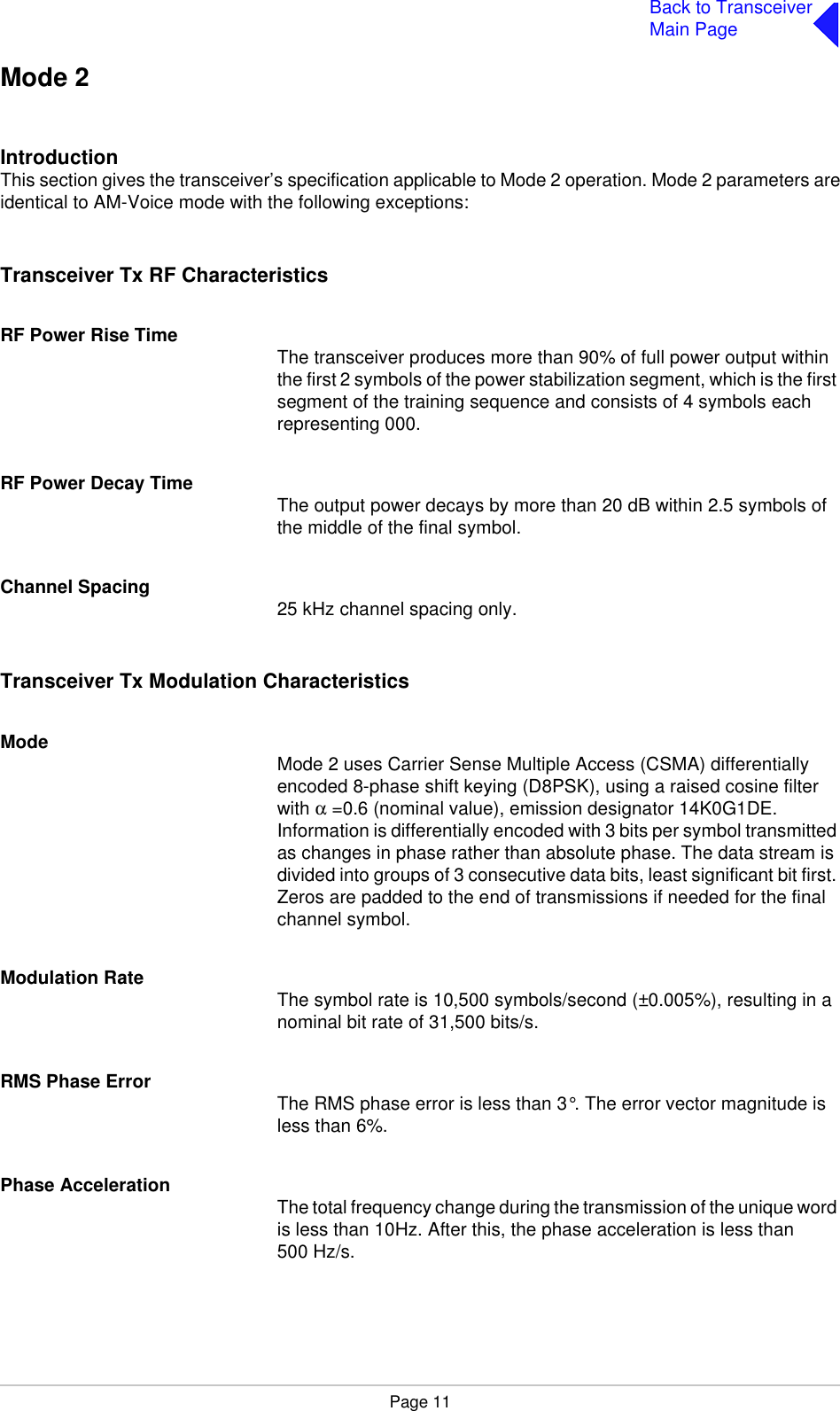

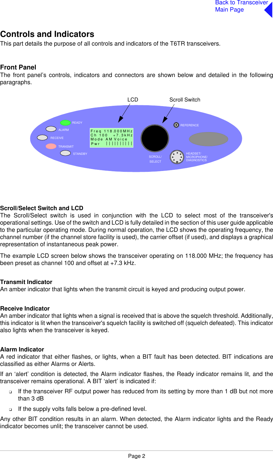
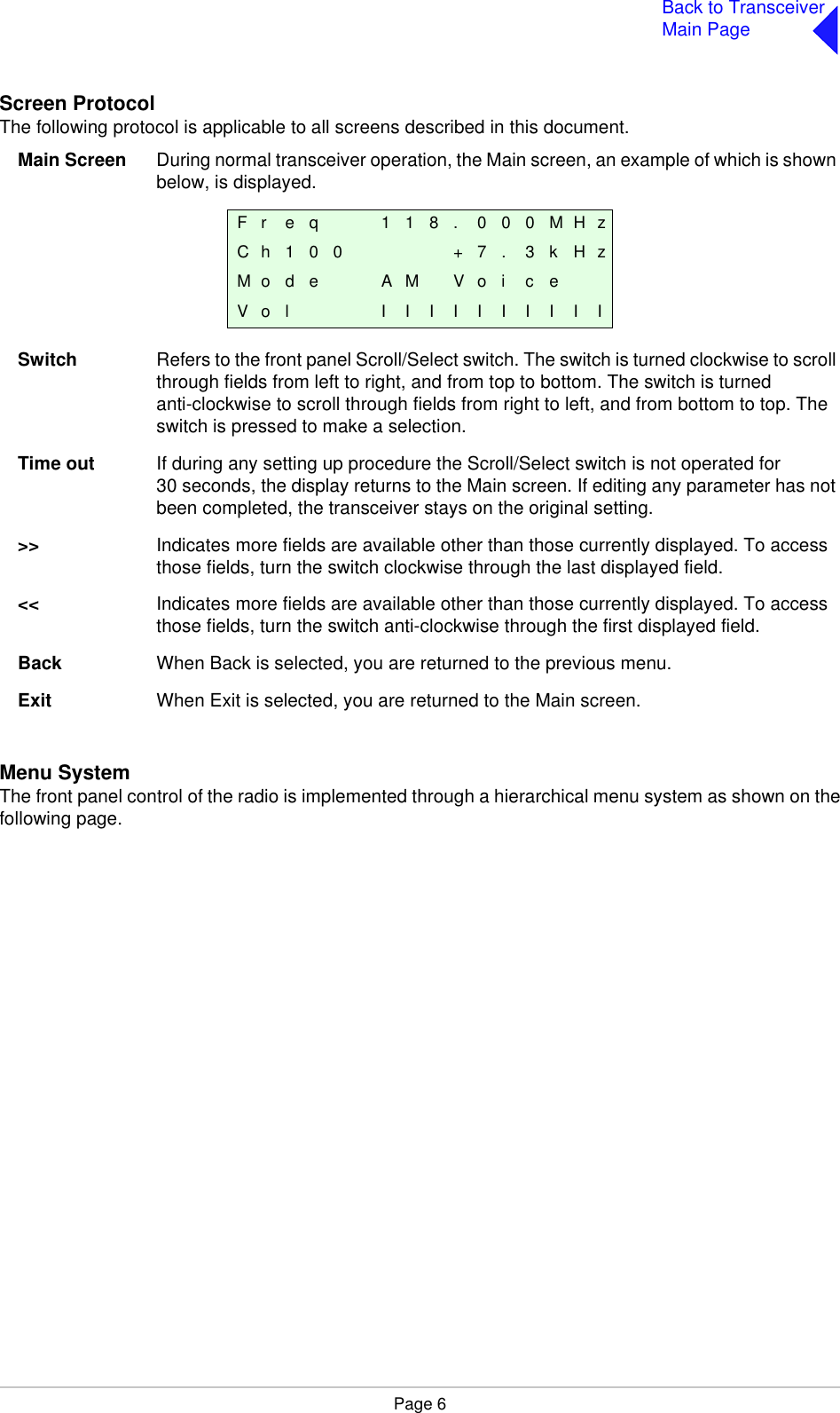
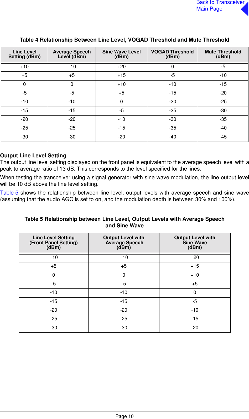
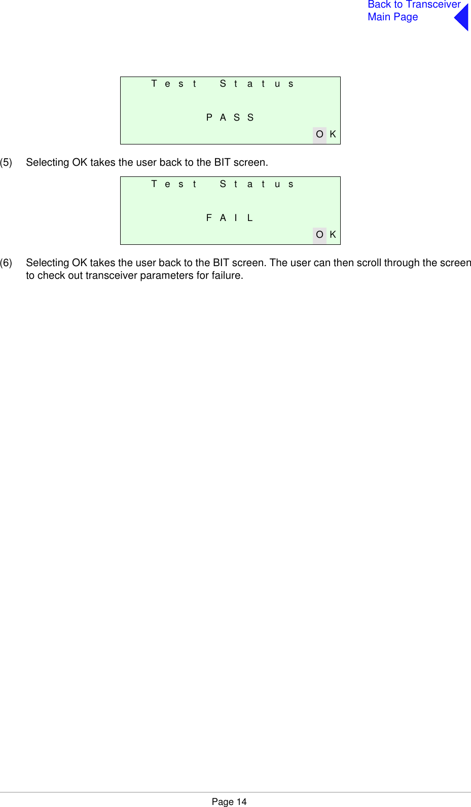
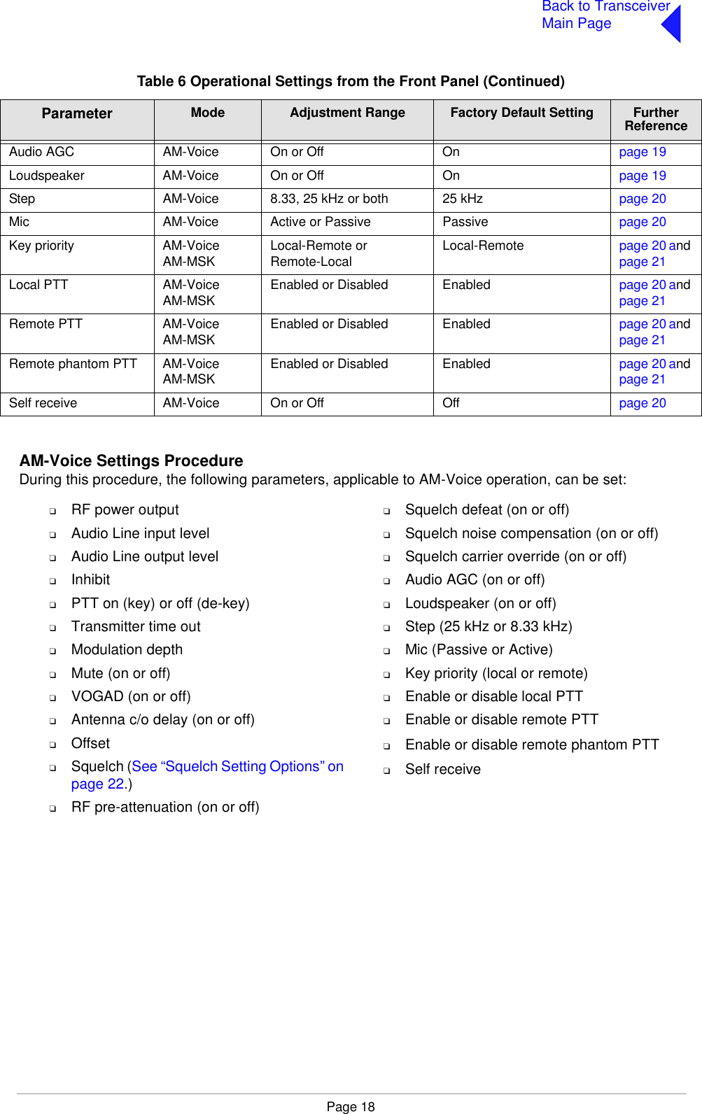
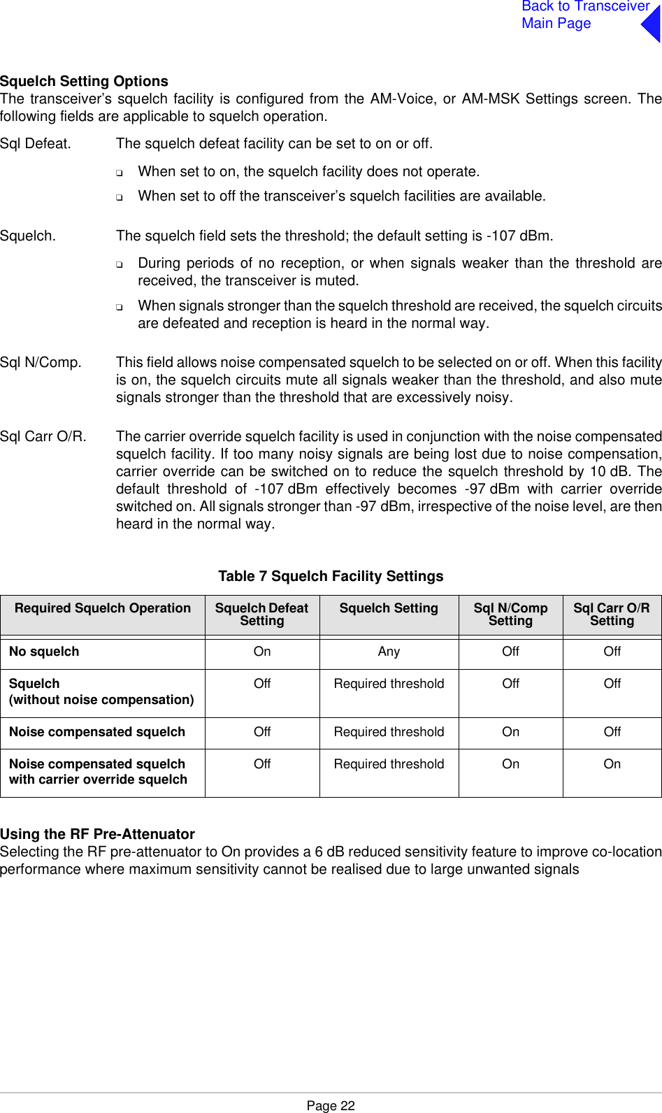
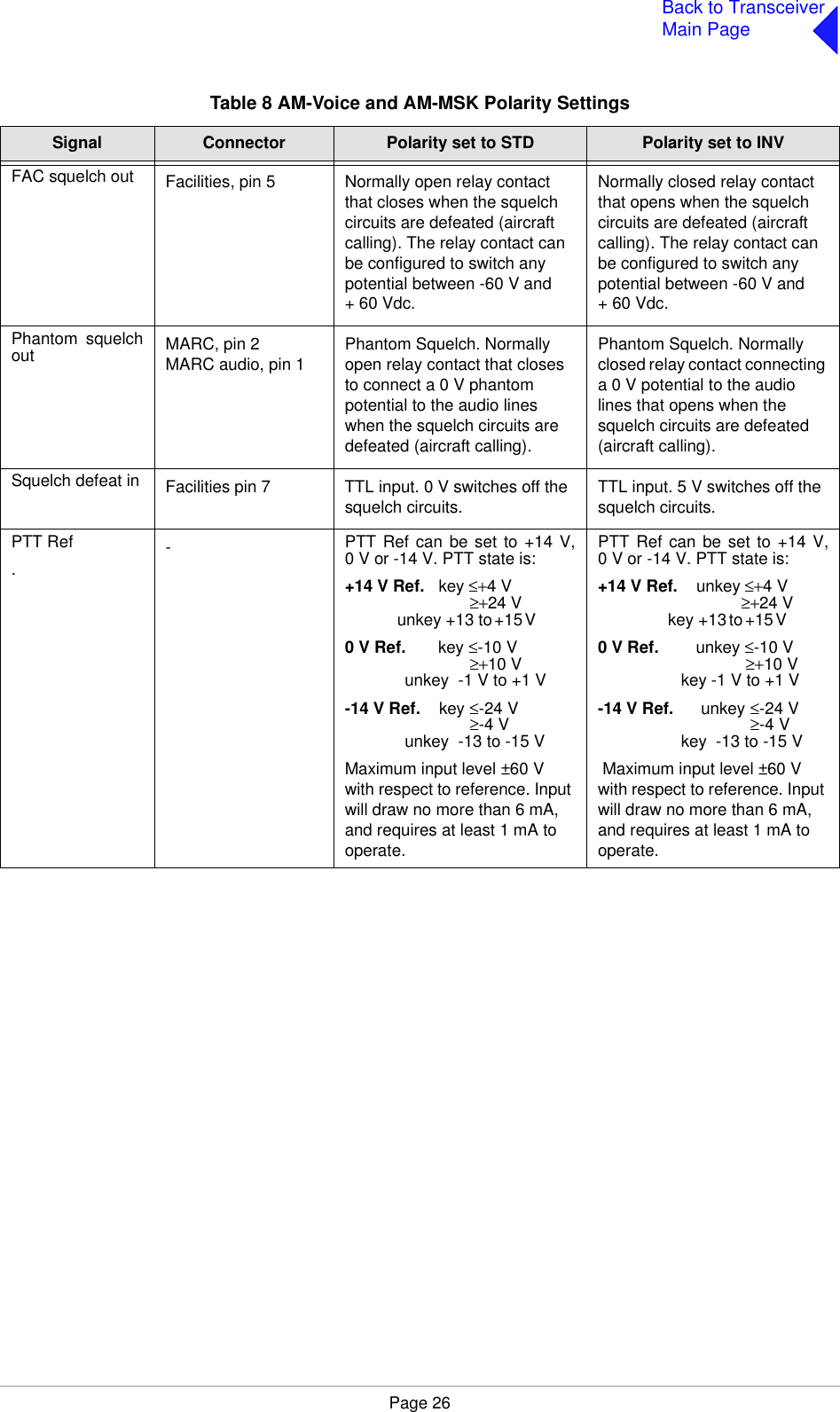

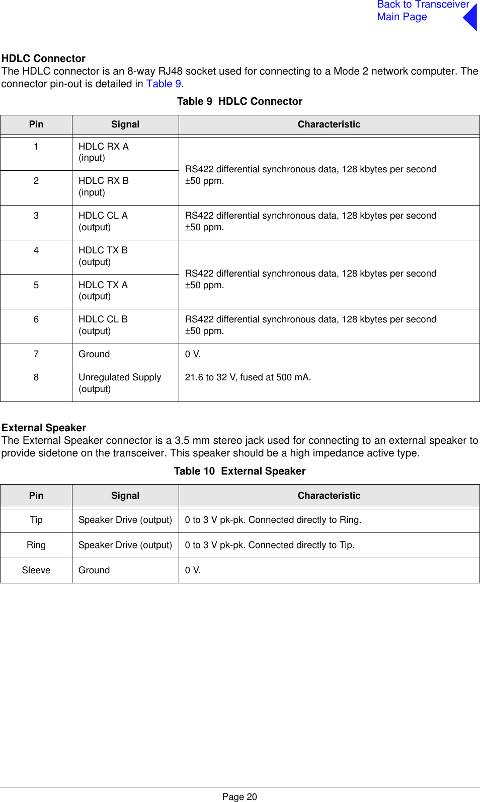
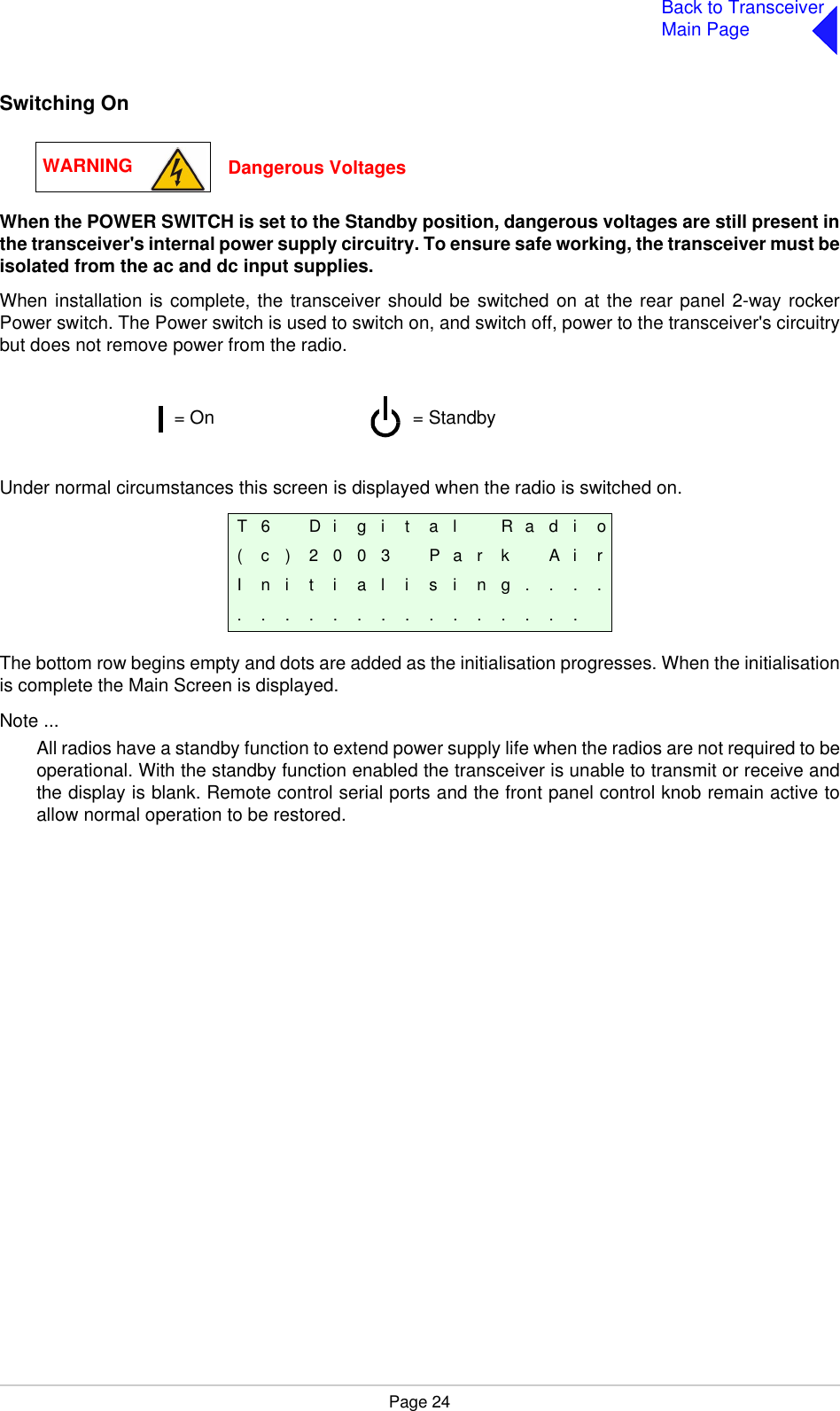
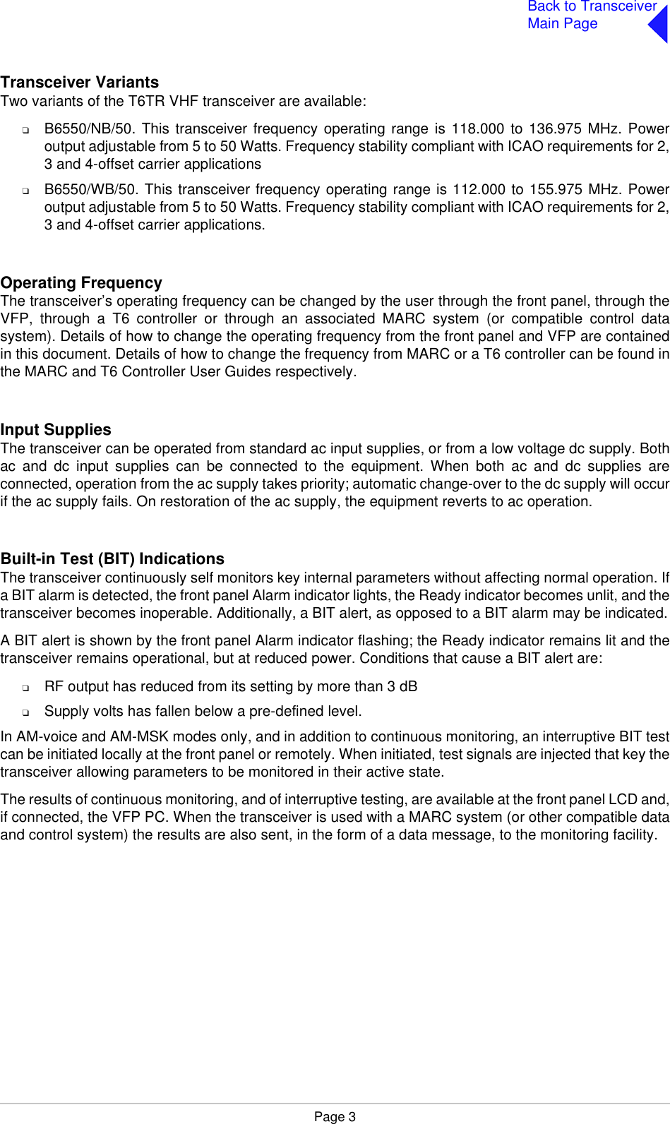
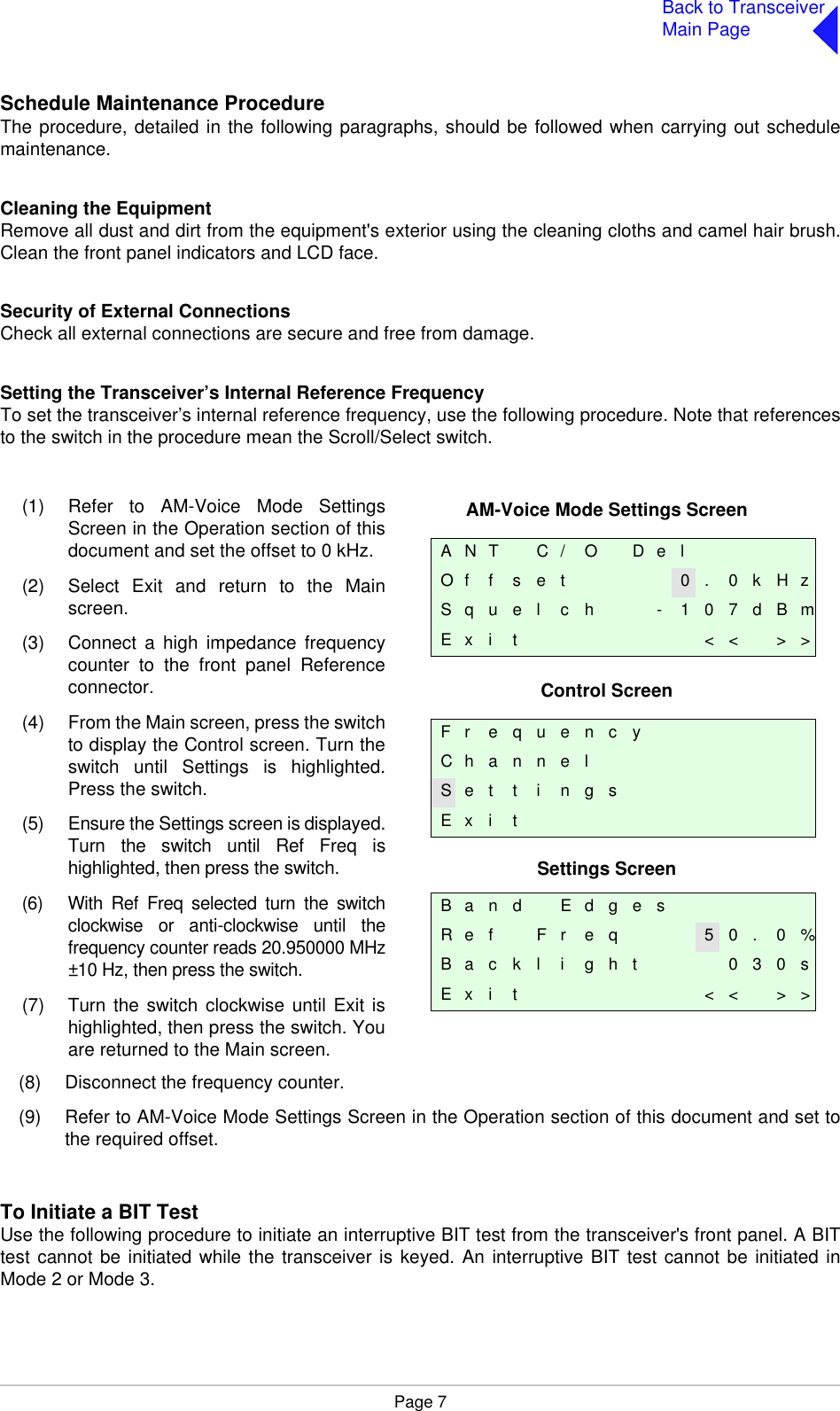
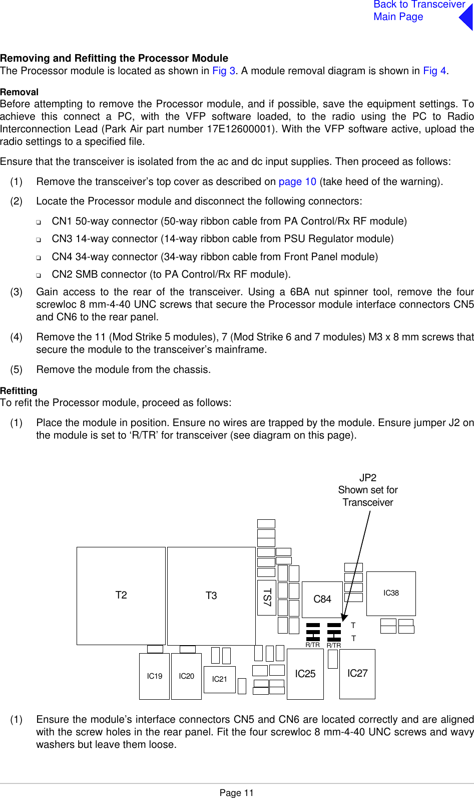
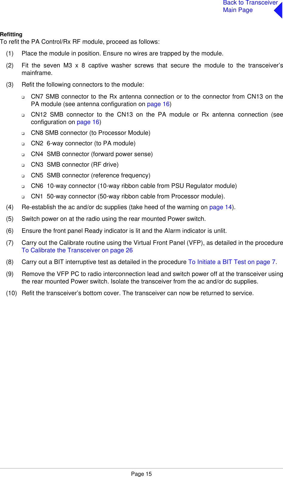
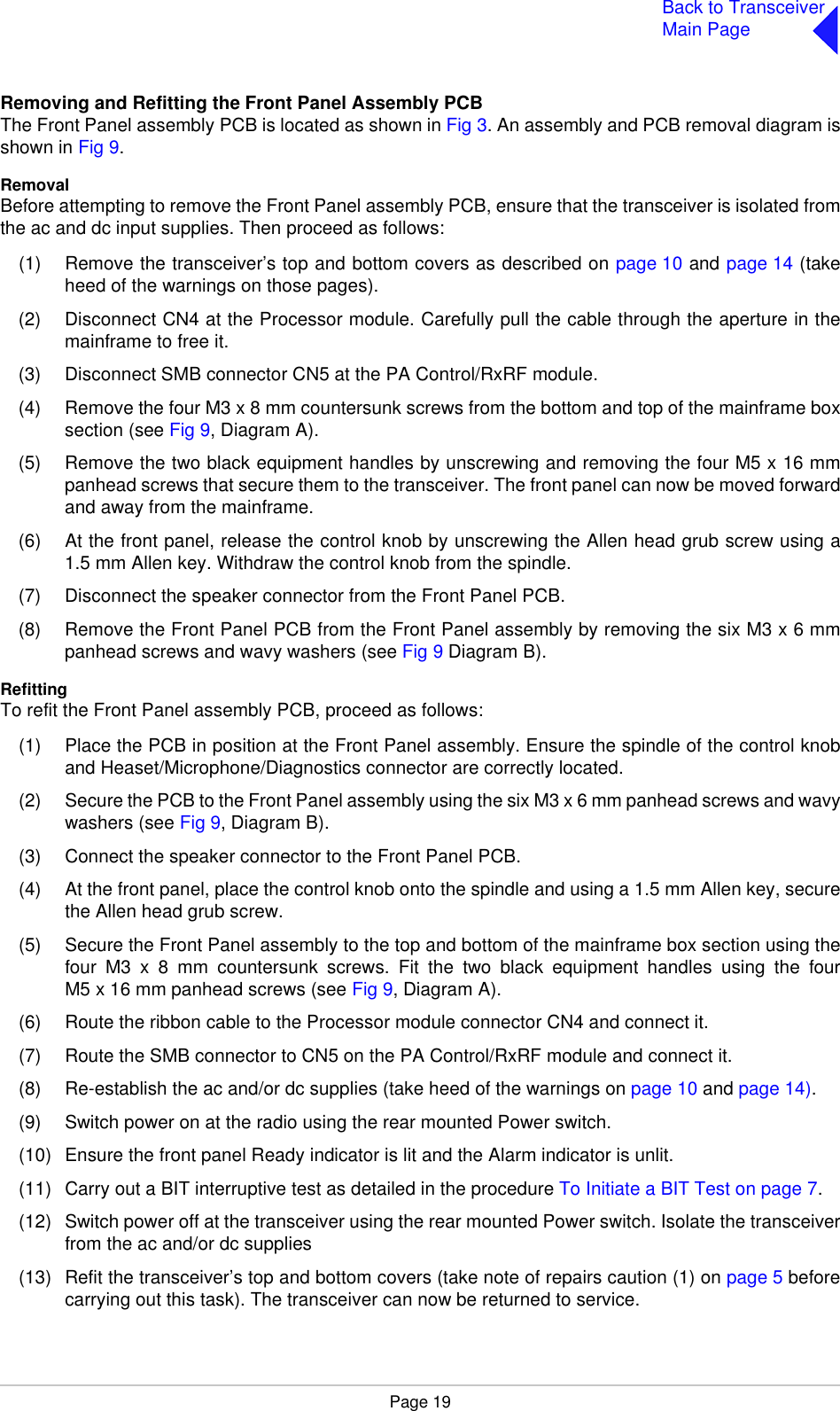
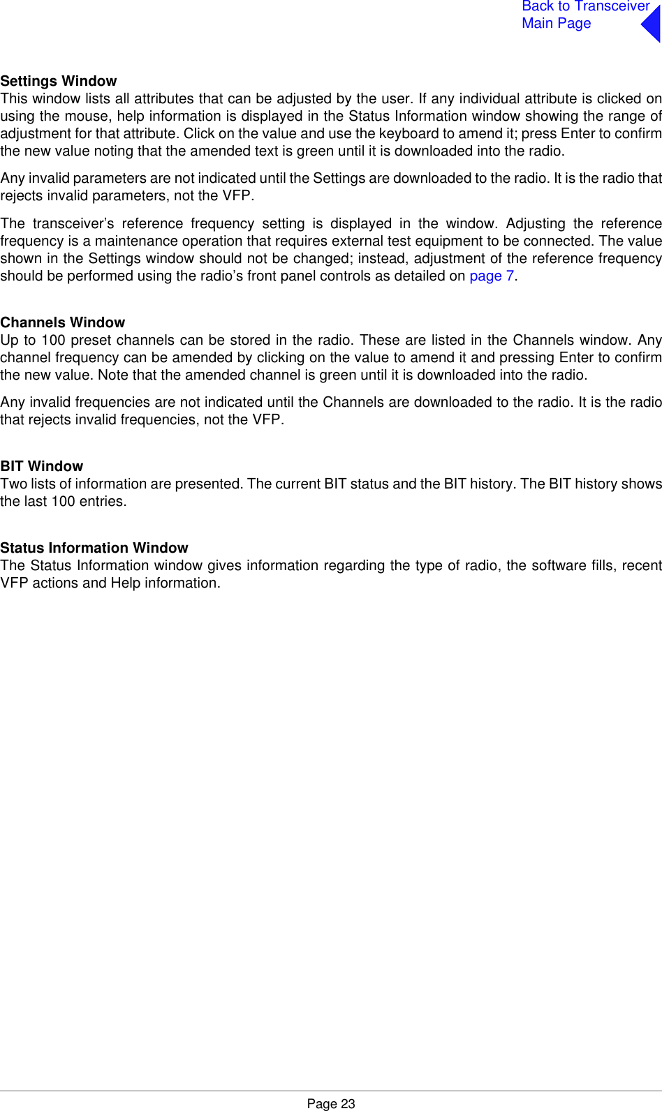
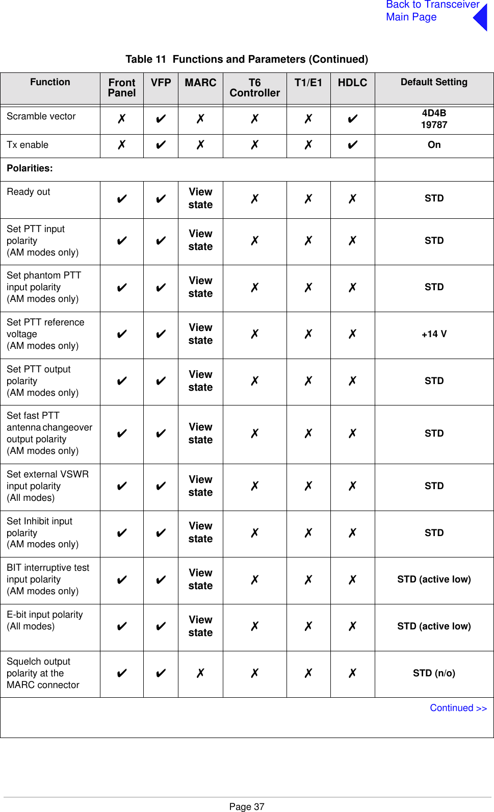
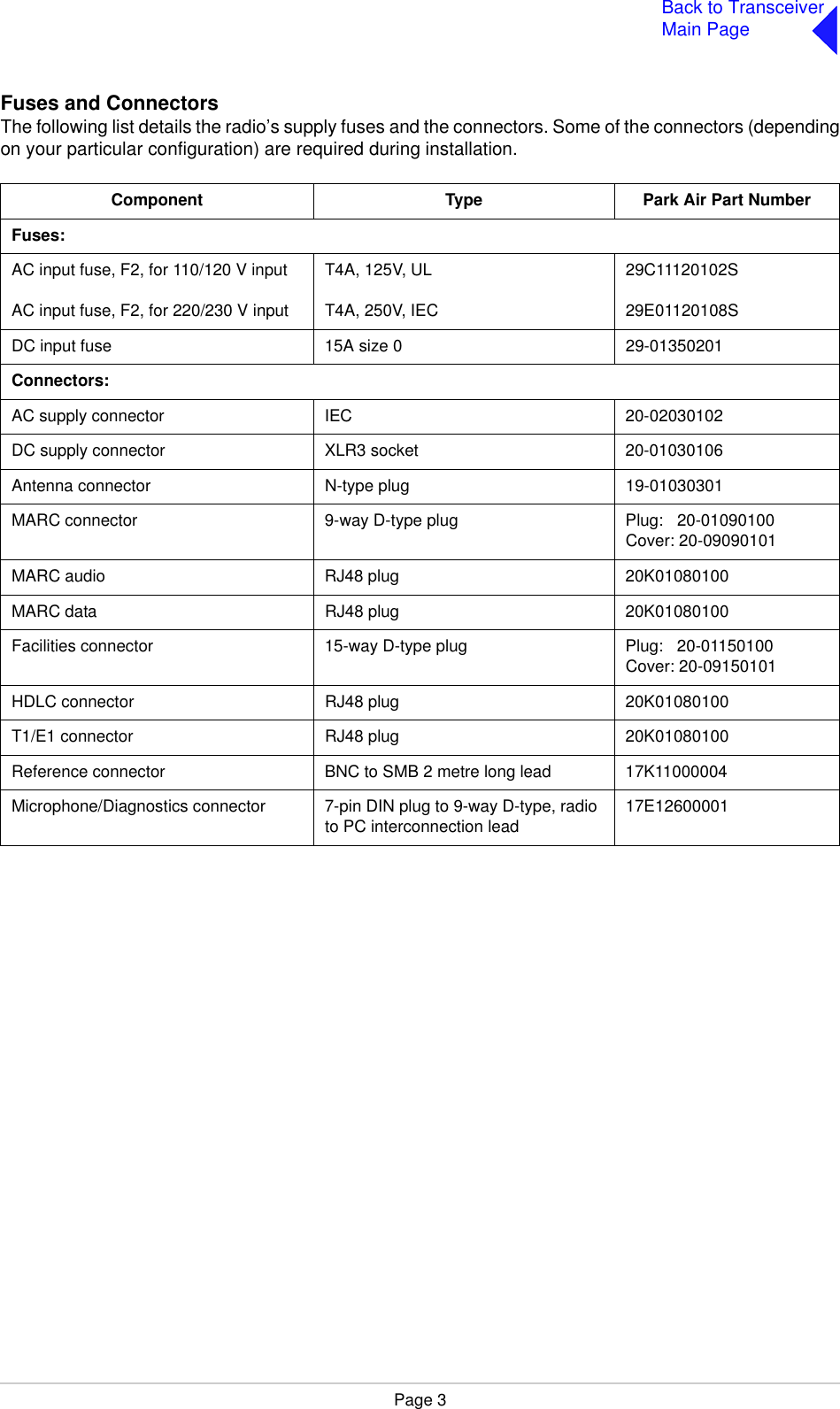
![Page 32Back to TransceiverMain PageSoftware Configuration ScreensSoftware configuration screens are as follows:T 6 V H F 5 0 W T X1 1 8 - 1 3 6 . 9 7 5 M H zE x i t > >B o o t S o f t w a r e6 5 - x x x x x x x x / v vE x i t < < > >B a s e S o f t w a r e6 5 - x x x x x x x x / v vE x i t < < > >M o d e S o f t w a r e6 5 - x x x x x x x x / v v[ D e s c r i p t i o n ]E x i t < < > >F i l l 1 S o f t w a r e6 5 - x x x x x x x x / v v[ D e s c r i p t i o n ]E x i t < < > >F i l l 2 S o f t w a r e6 5 - x x x x x x x x / v v[ D e s c r i p t i o n ]E x i t < < > >Second line variation for WB radios reads 112-155.975 MHz.65-xxxxxxxx represents the software part number and /v v represents its version.65-xxxxxxxx represents the software part number and /v v represents its version.Current mode running. 65-xxxxxxxx represents the software part number and /v v represents its version.65-xxxxxxxx represents the software partnumber and /v v represents its version.65-xxxxxxxx represents the software partnumber and /v v represents its version.](https://usermanual.wiki/Park-Air-Systems/B6550-S2.User-guide/User-Guide-587255-Page-48.png)
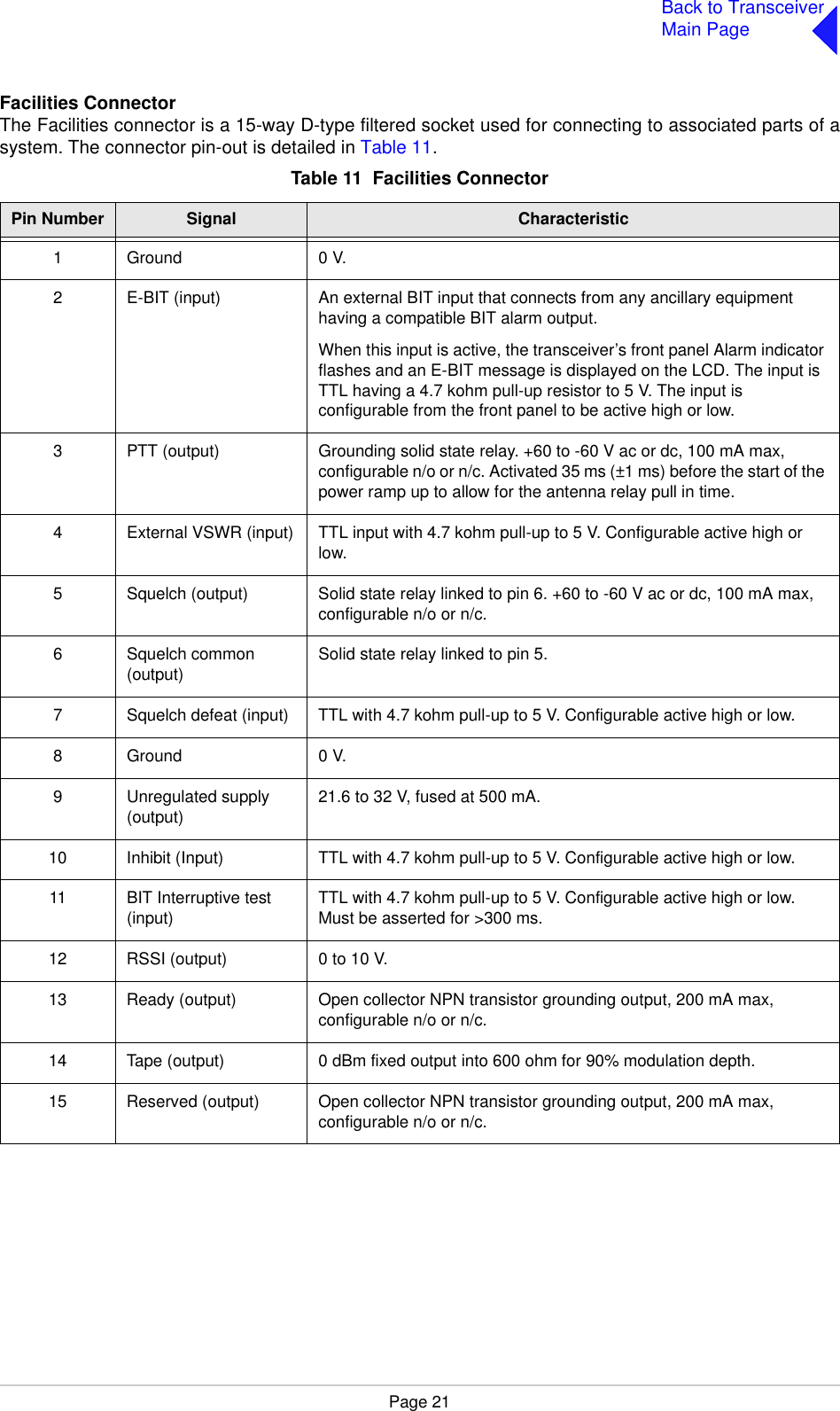
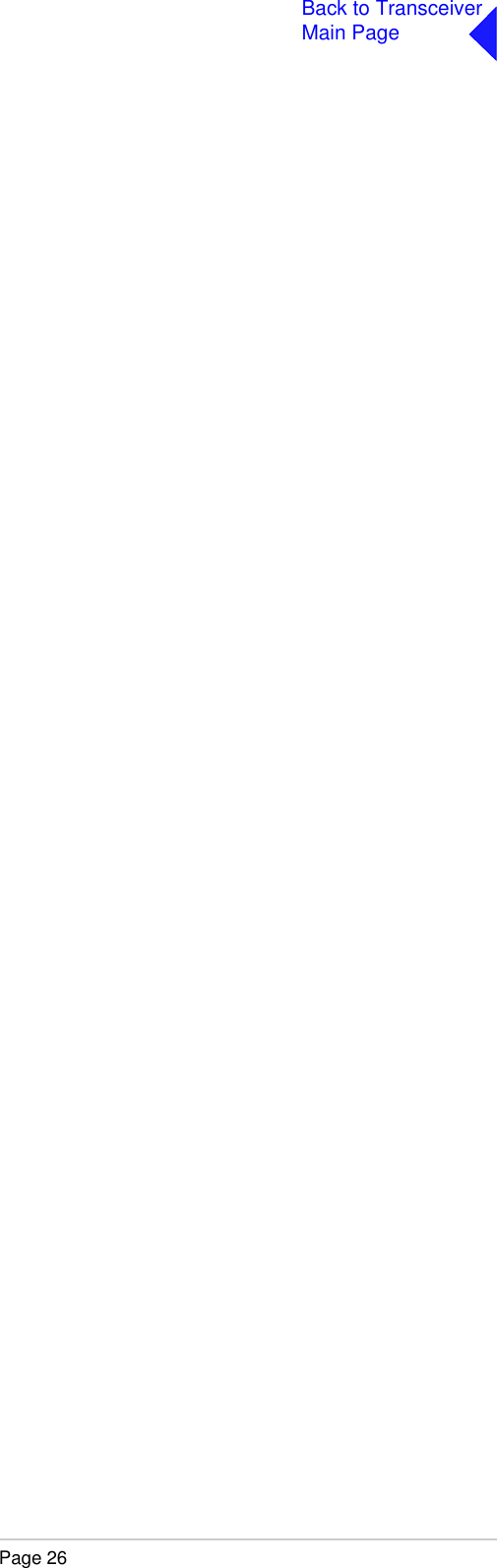
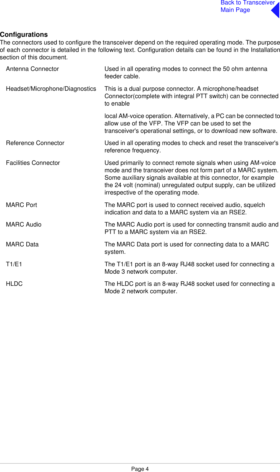
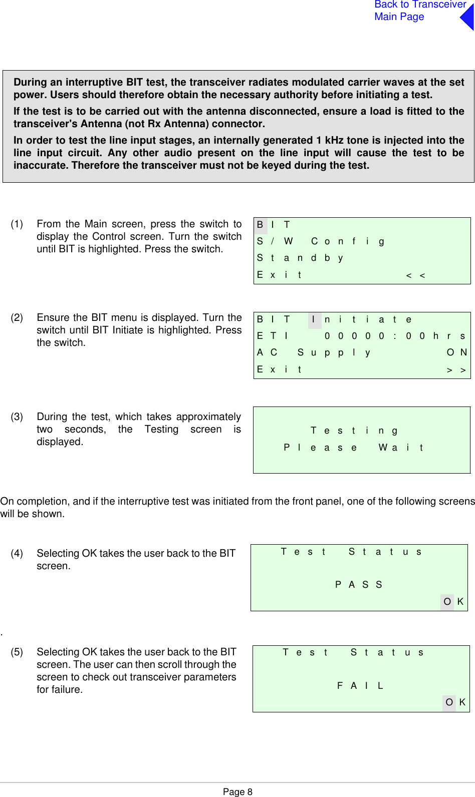
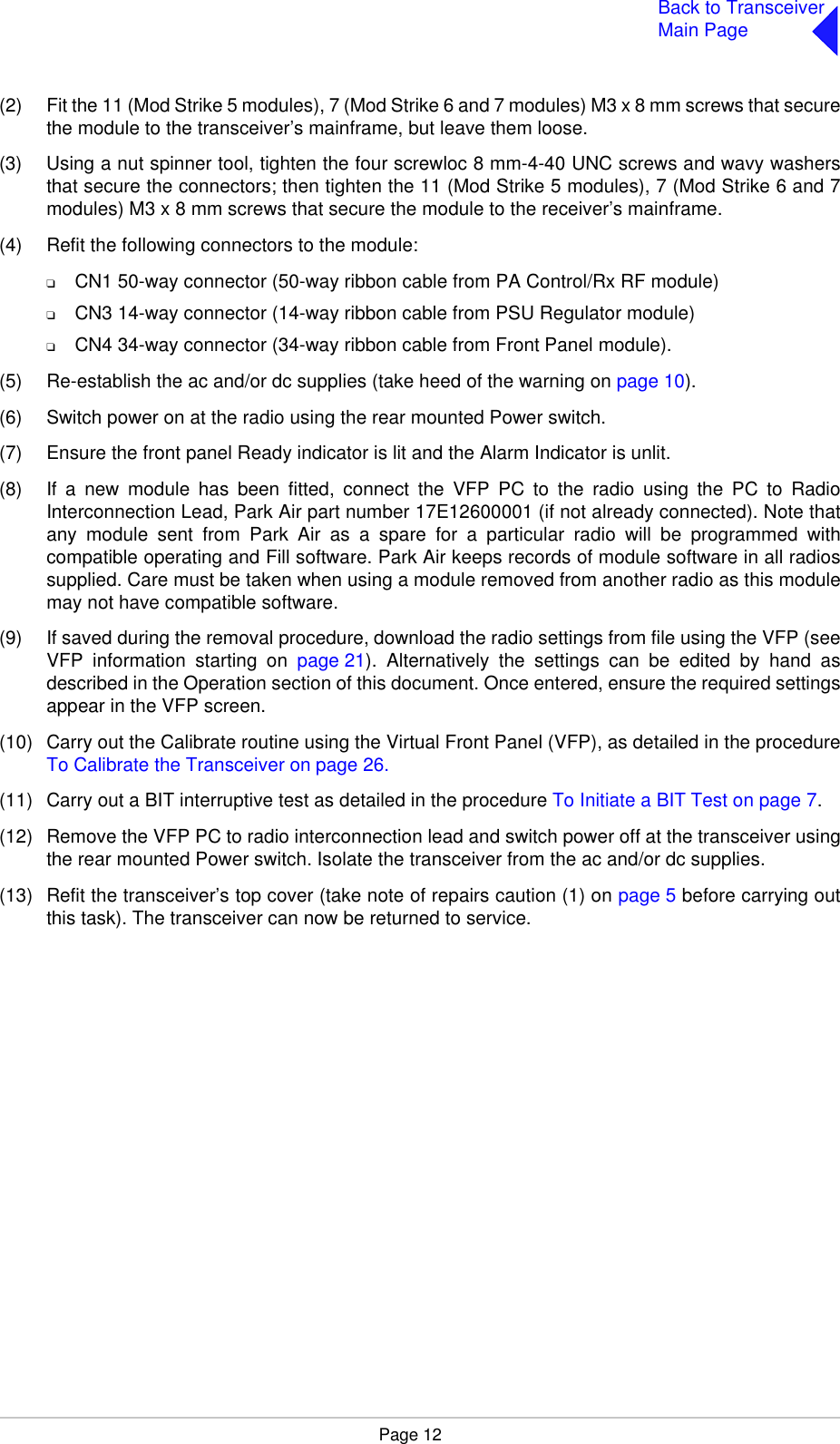
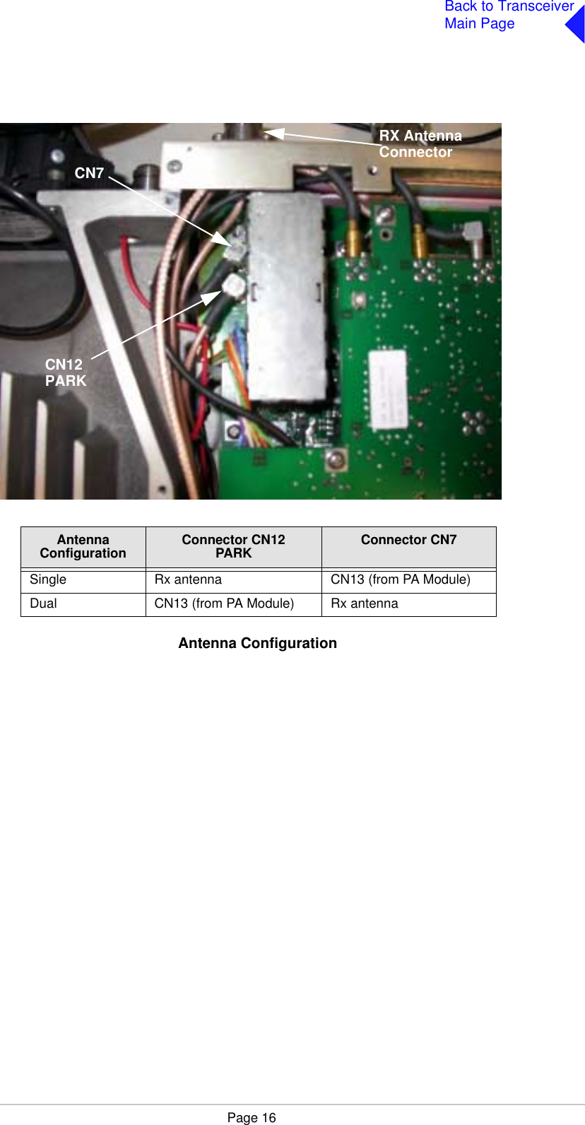
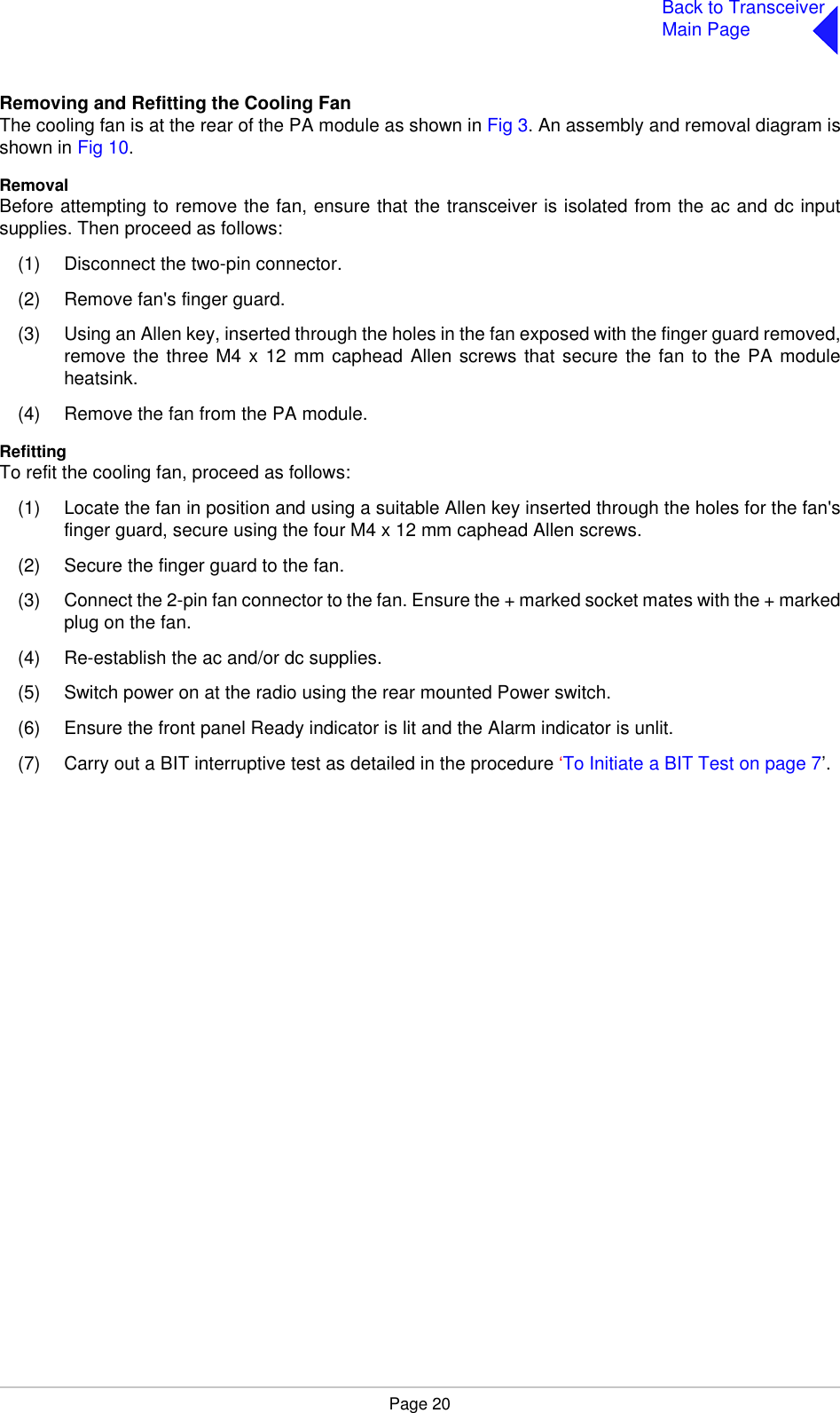
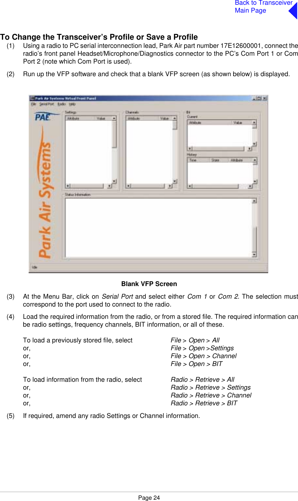
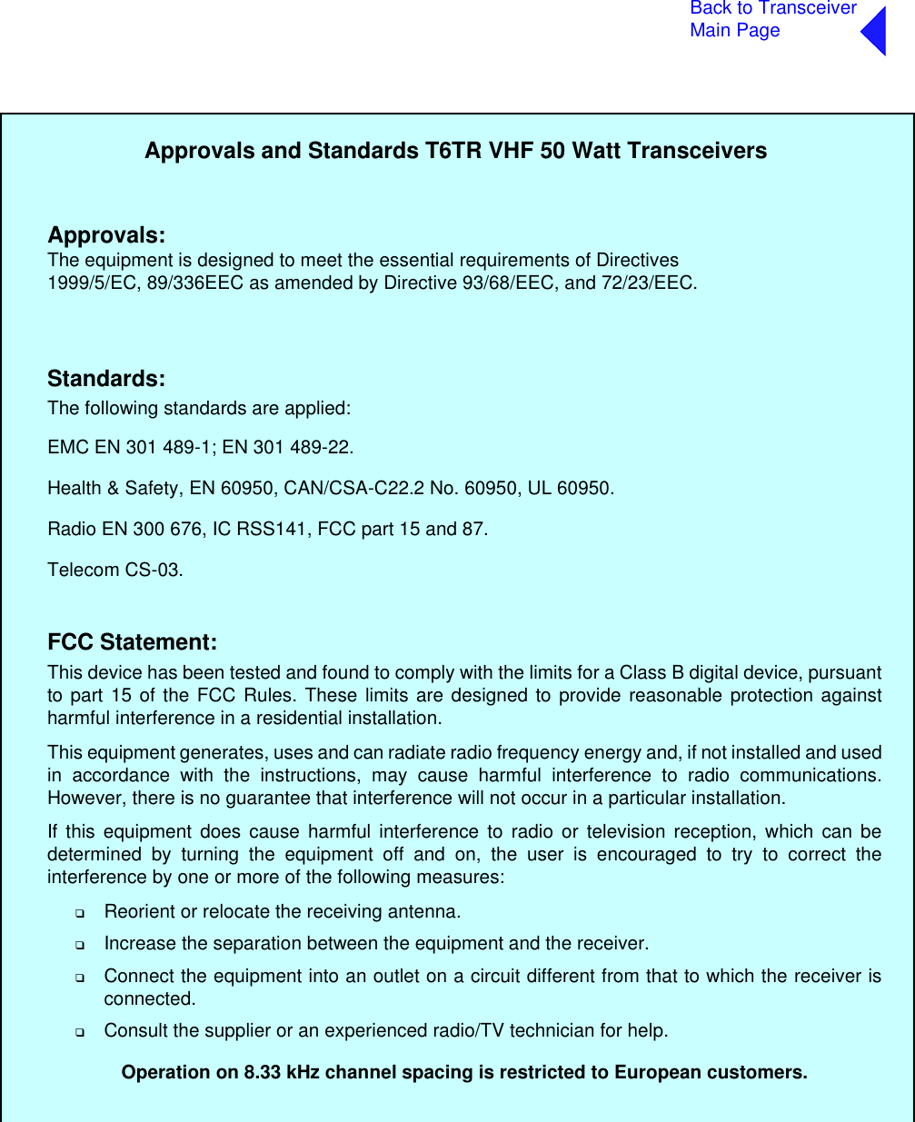
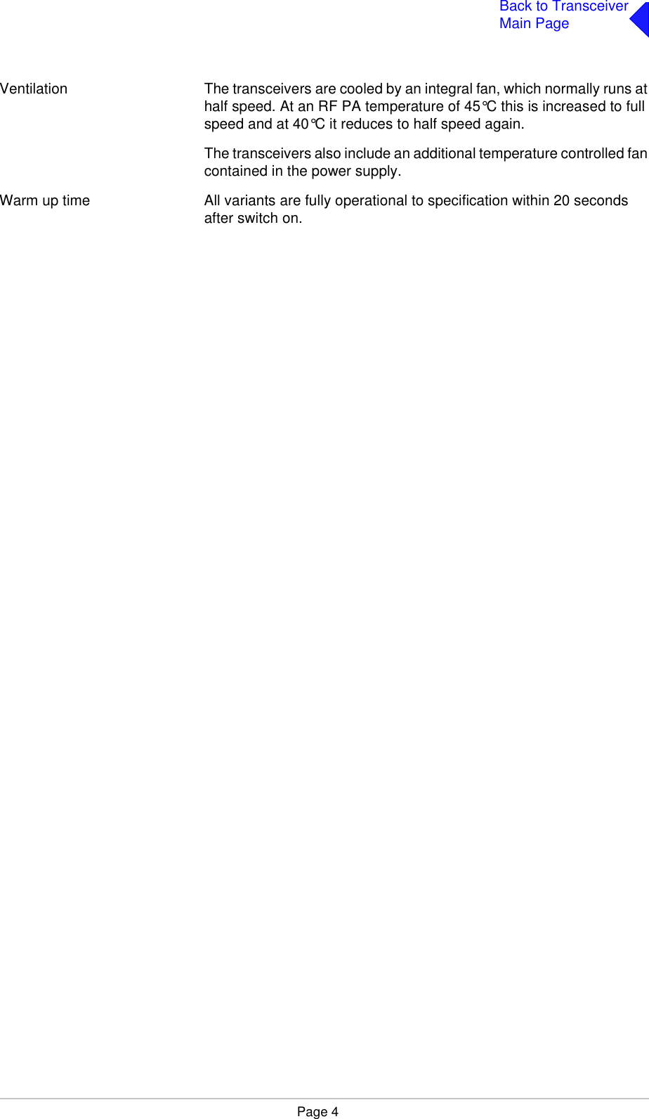
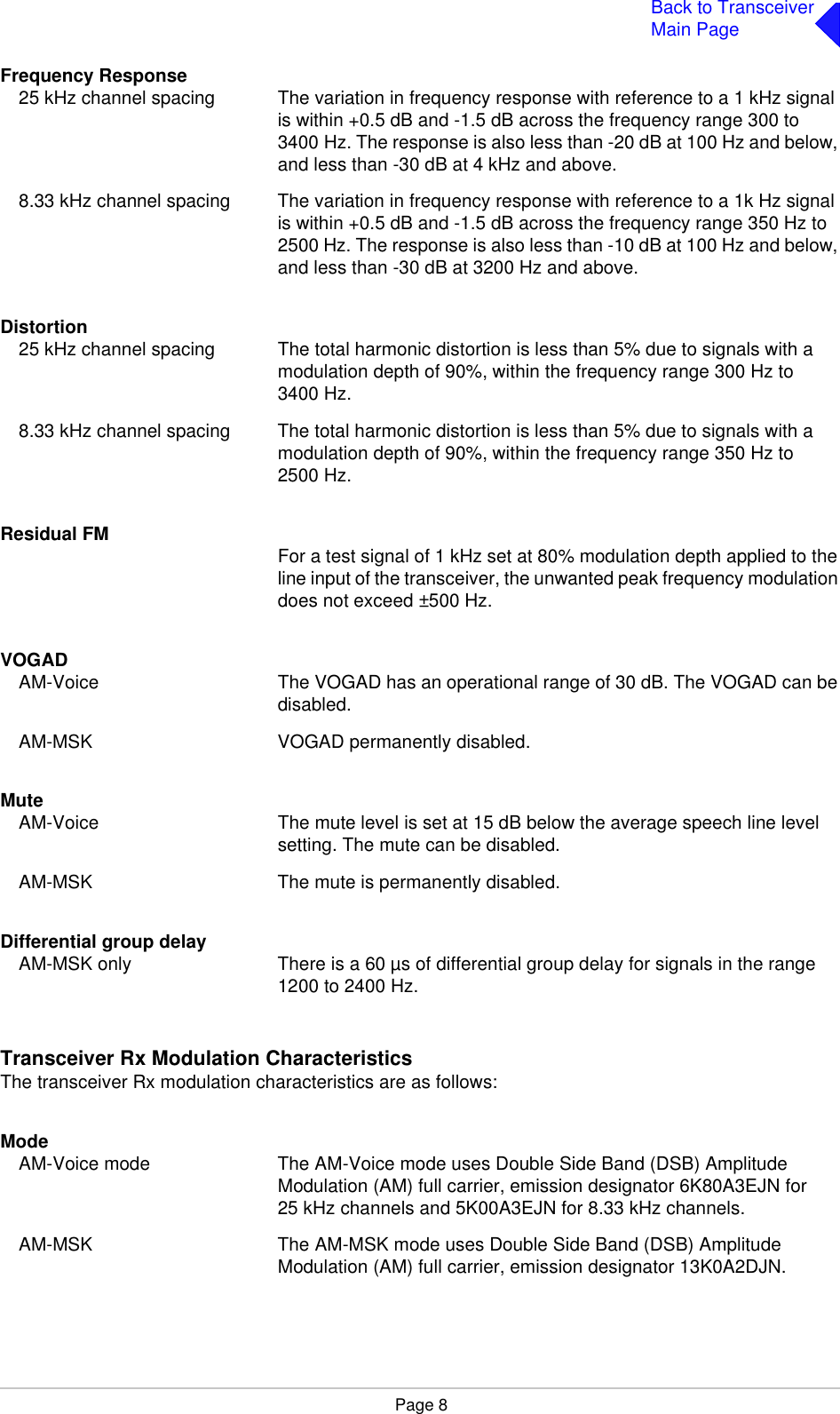
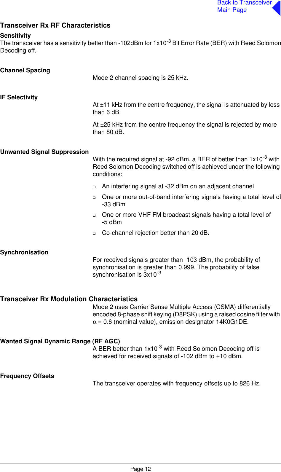
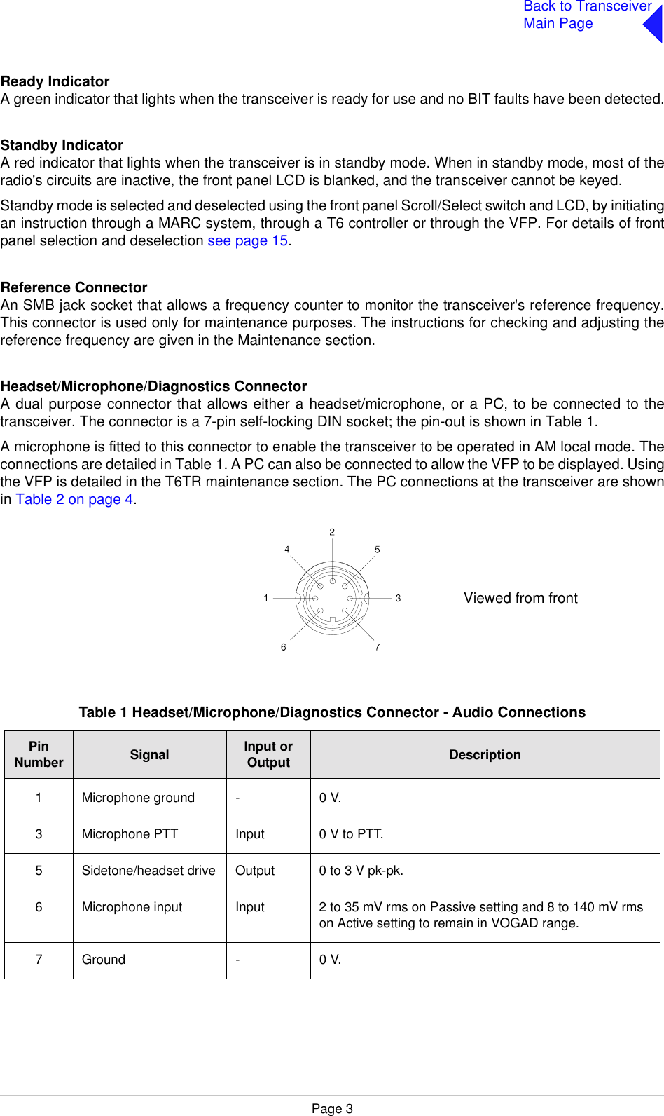
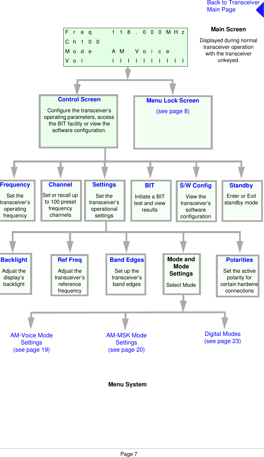
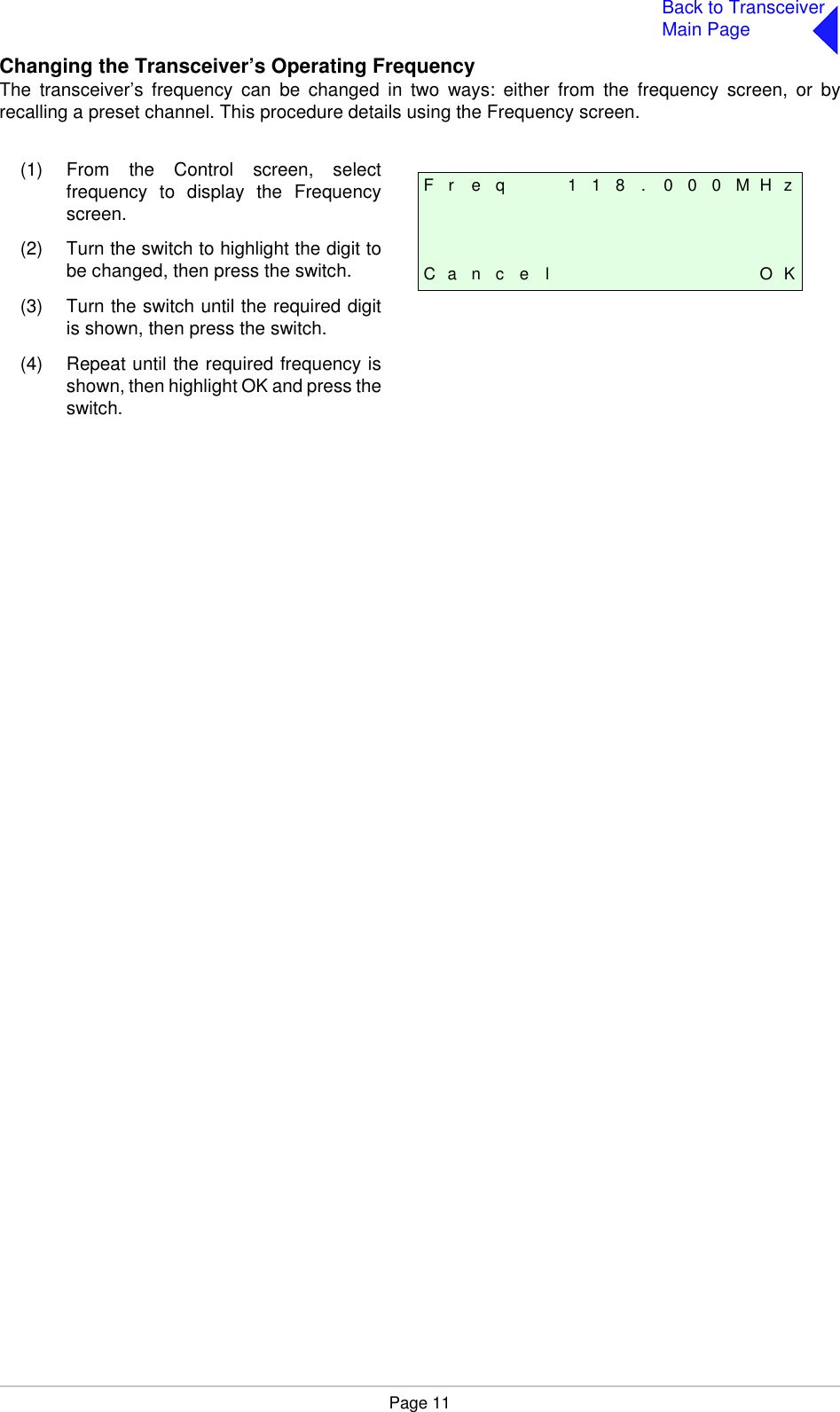
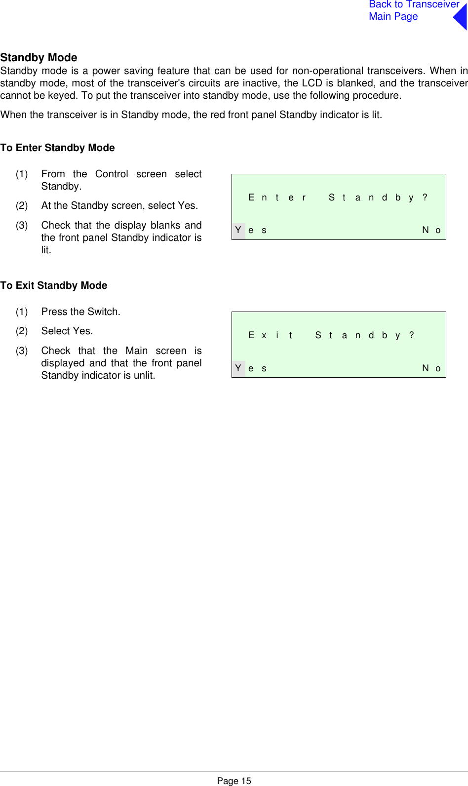
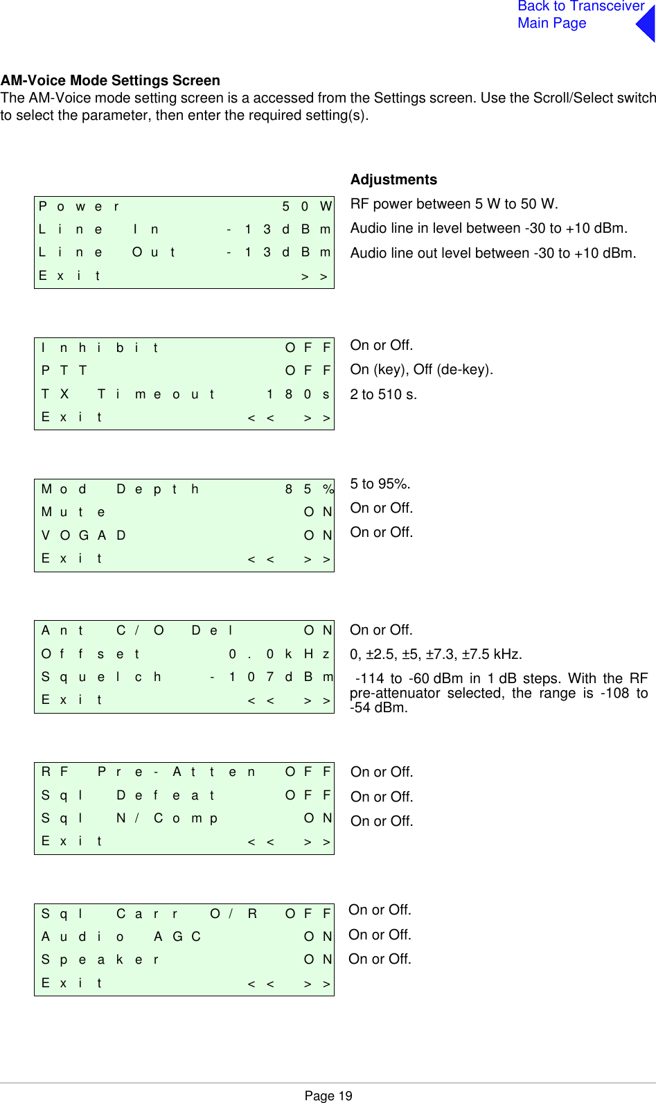
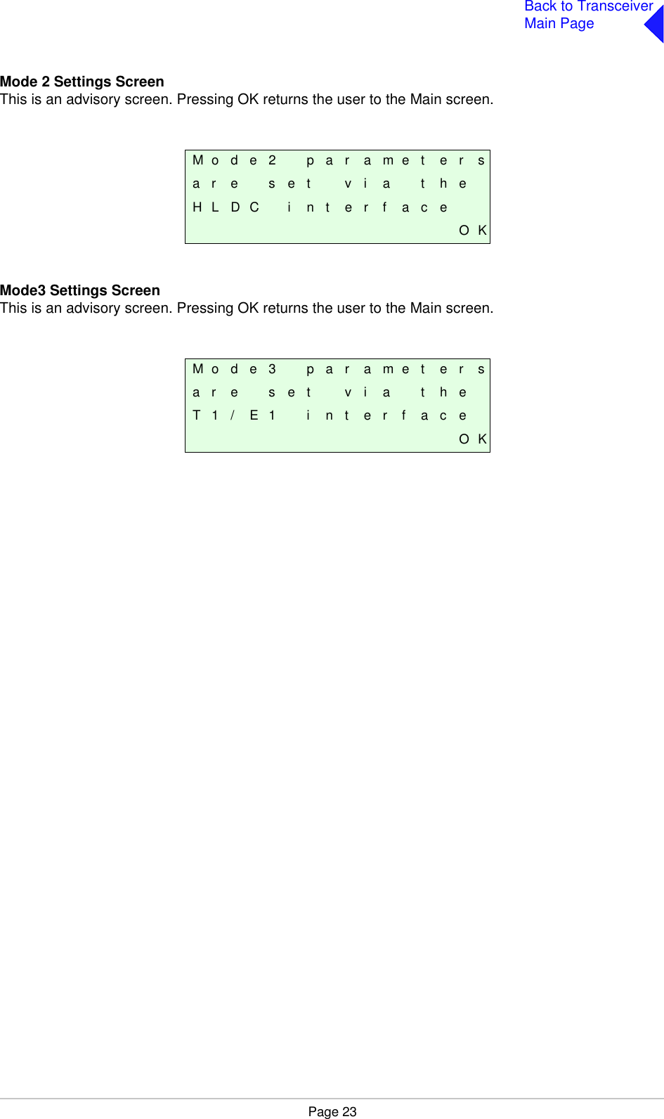
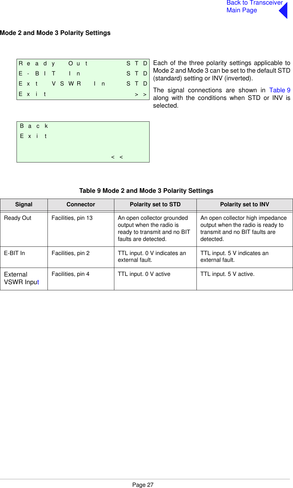
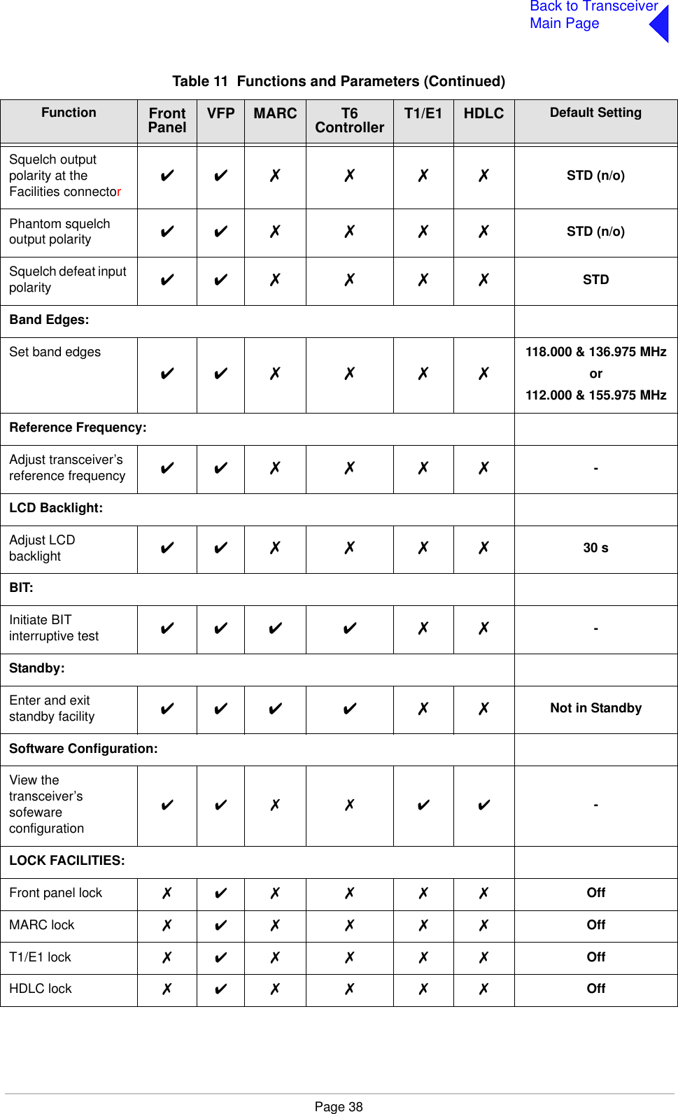
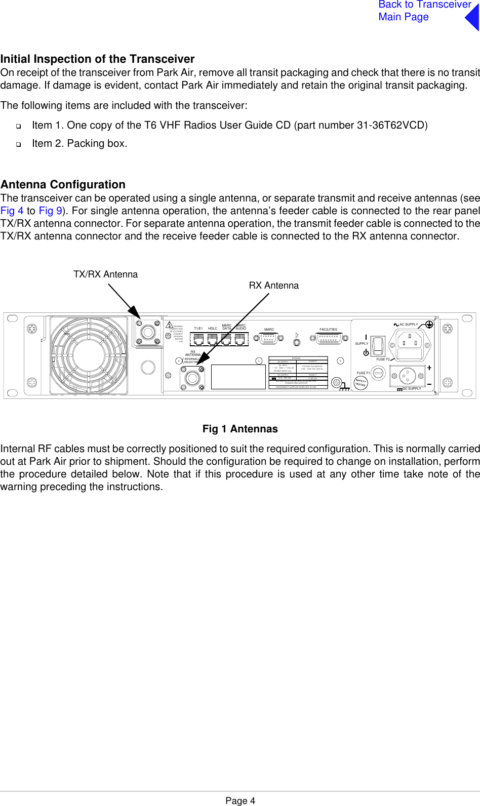
![Page 33Back to TransceiverMain PageBand EdgesThe frequency range of the transceiver is 118 to 136.975 MHz for the B6550/NB version, or 112 to155.975 MHz for the B6550/WB version.If required, reception can be limited to either one or two smaller parts of the frequency band by settingthe band edges BE1 to BE4. Reception is possible between BE1 and BE2 frequencies, and frequenciesbetween BE3 and BE4. Table 10 Band Edge ValuesBE1 BE2 BE3 BE4B6550/NB set so that the full frequency range can be received. 118.000 136.975 118.000 136.975B6550/WB set so that the full frequency range can be received. 112.000 155.975 112.000 155.975Example: Transceiver set to transmit and receive only those frequencies in the range 120 to 130 MHz. 120.000 130.000 120.000 130.000Example: Transceiver set to transmit and receive only those frequencies in the ranges 120 to 125 MHz and 130 to 135 MHz. 120.000 125.000 130.000 135.000F i l l 3 S o f t w a r e6 5 - x x x x x x x x / v v[ D e s c r i p t i o n ]F i l l 4 S o f t w a r e6 5 - x x x x x x x x / v v[ D e s c r i p t i o n ]65-xxxxxxxx represents the software partnumber and /v v represents its version.65-xxxxxxxx represents the software partnumber and /v v represents its version.B E 1 1 1 8 . 0 0 0 M H zB E 2 1 3 6 . 9 7 5 M H zB E 3 1 1 8 . 0 0 0 M H zE x i t > >B E 4 1 3 6 . 9 7 5 M H zE x i t < <The Band Edge screen is accessed from theControl screen.Band edge frequencies can be set only inincrements of 25 kHz.If the transceiver is required to operate over thefull range, the band edge parameters must be setto the lowest and highest values in the range (seeTable 10).](https://usermanual.wiki/Park-Air-Systems/B6550-S2.User-guide/User-Guide-587255-Page-49.png)
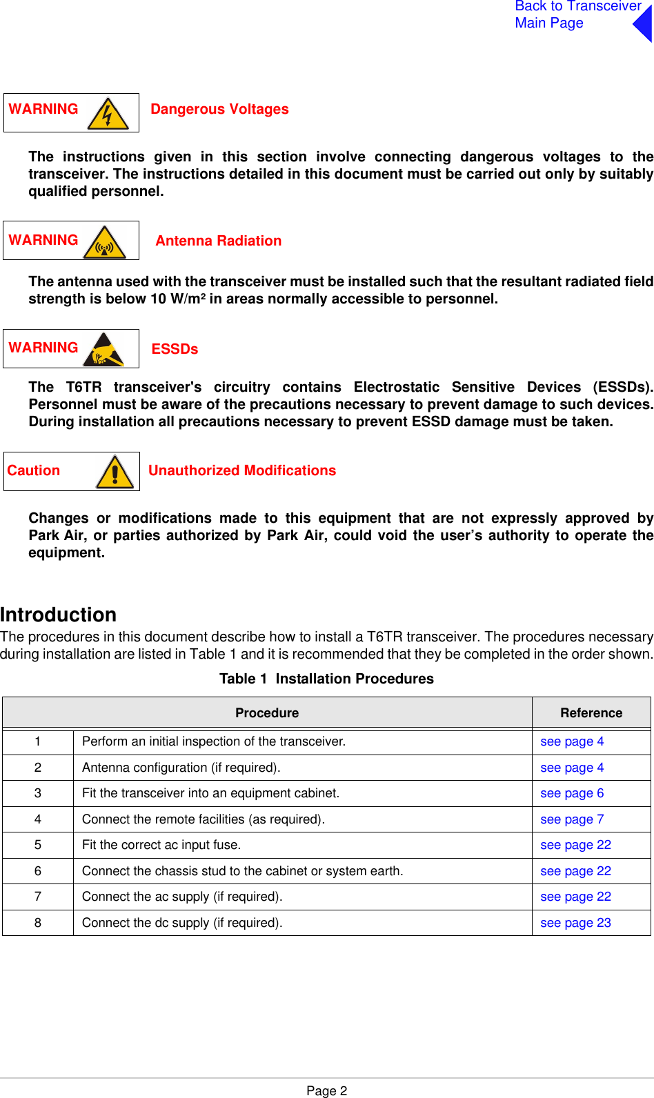
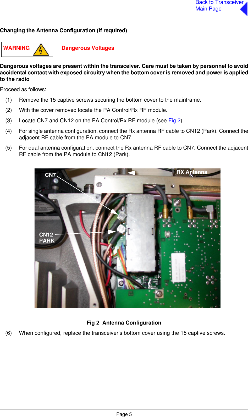
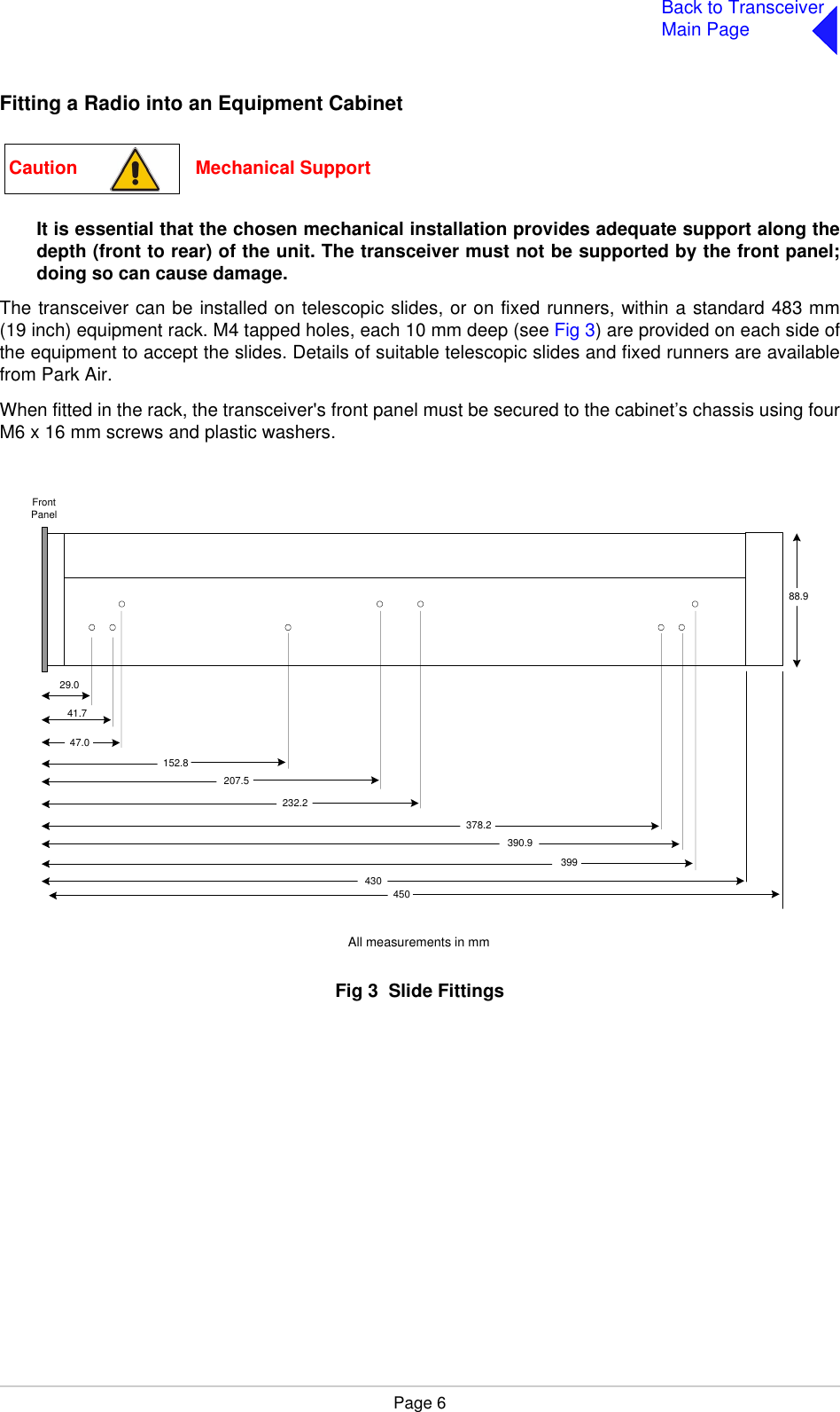
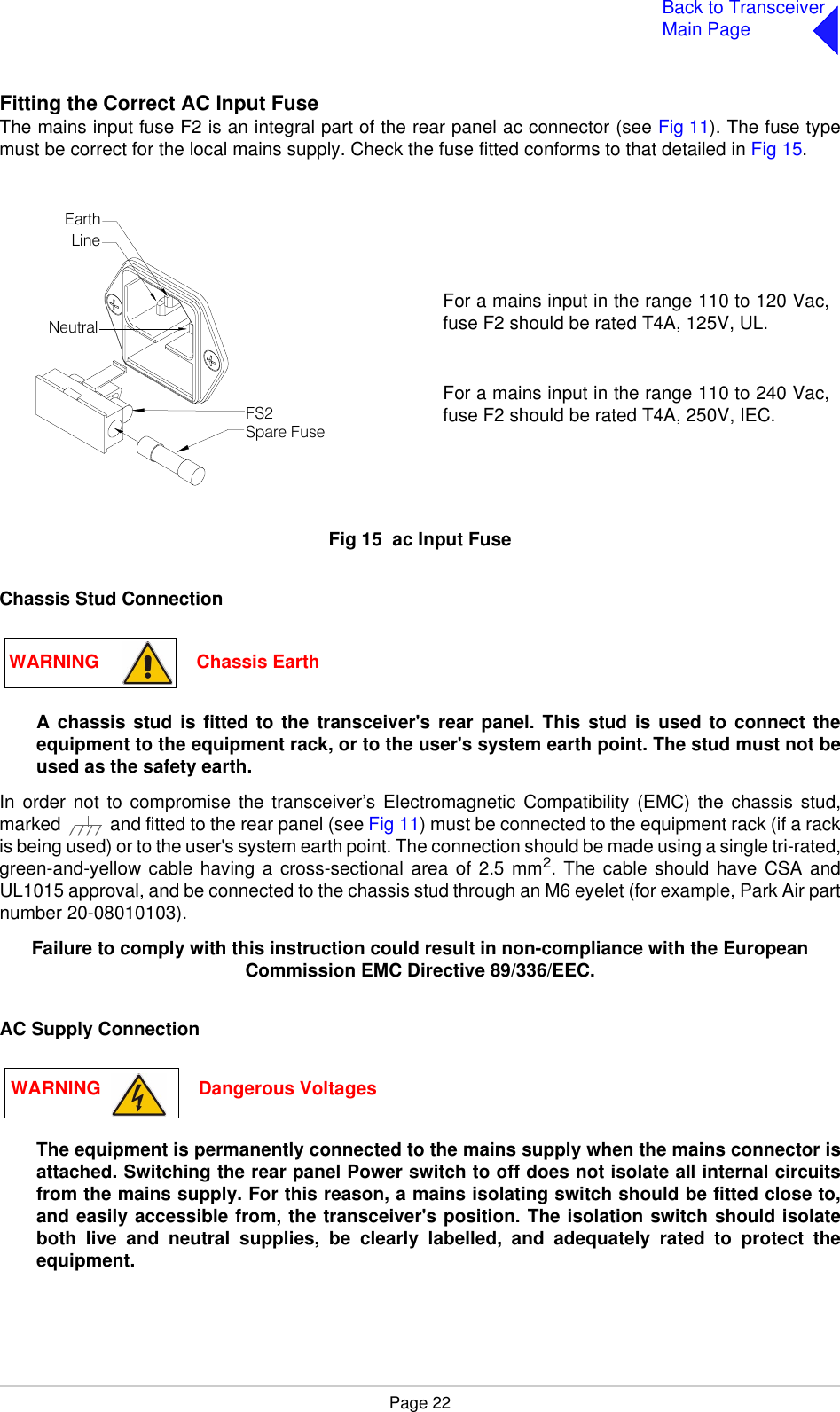
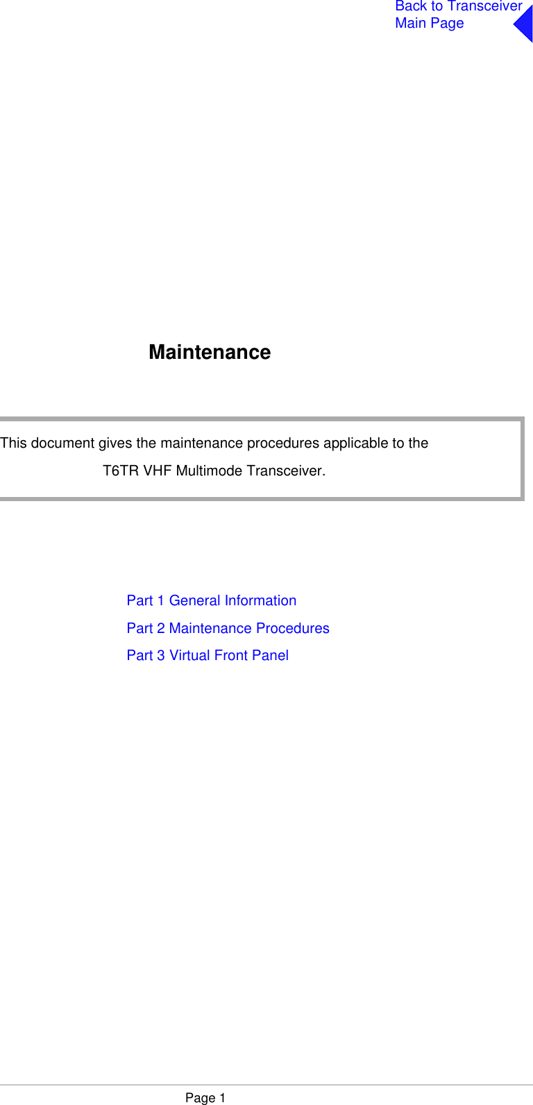
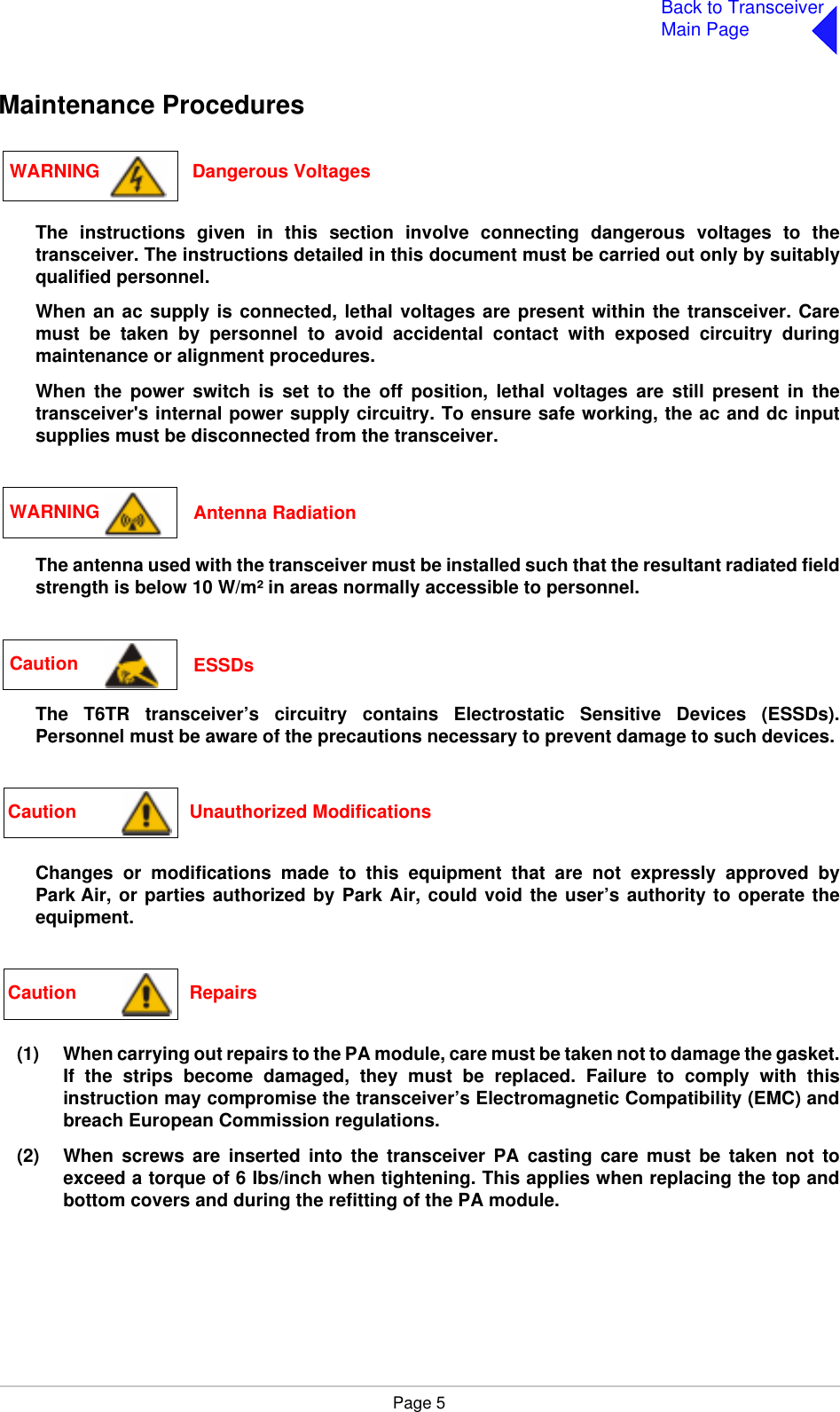
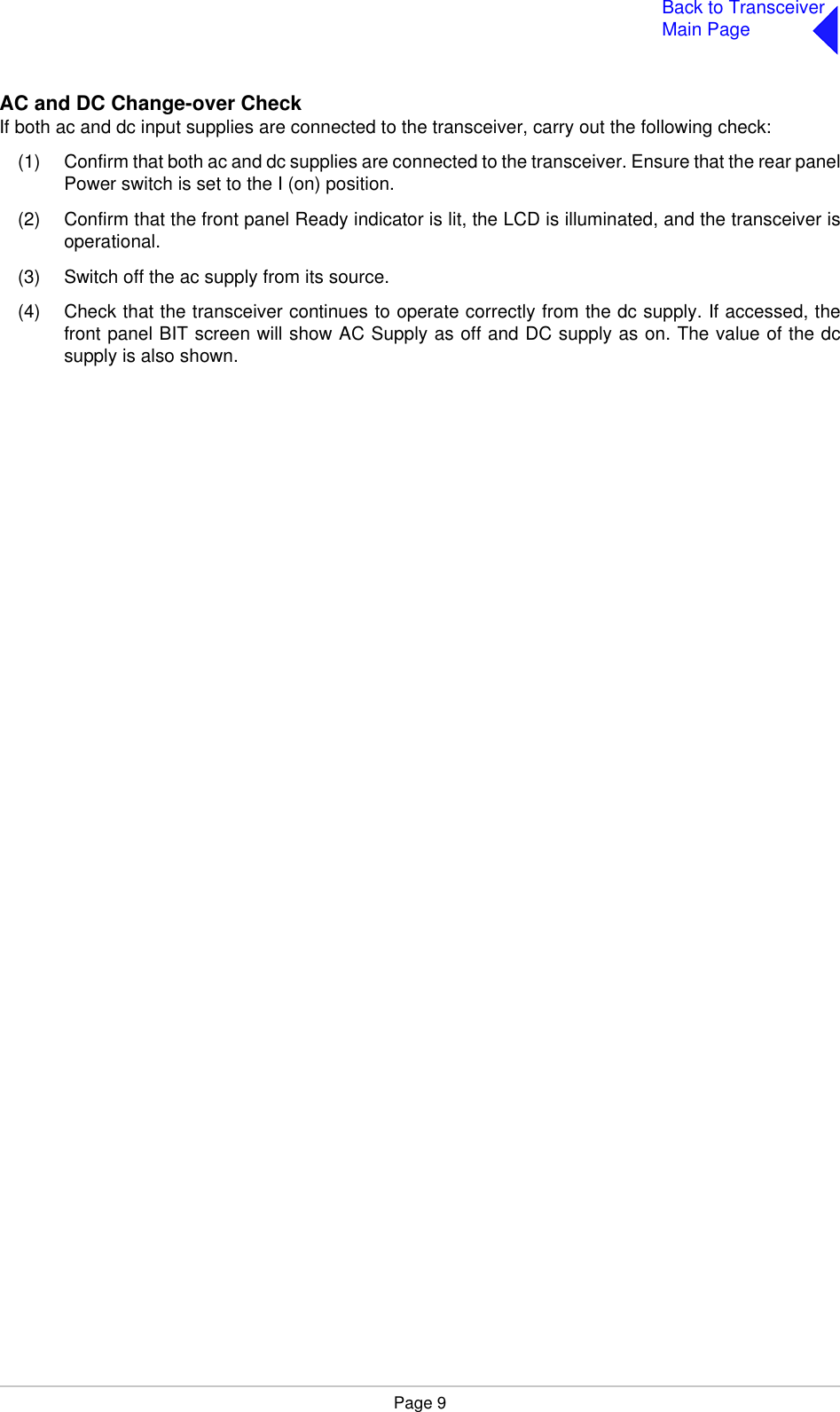
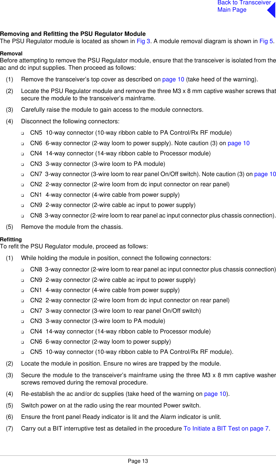
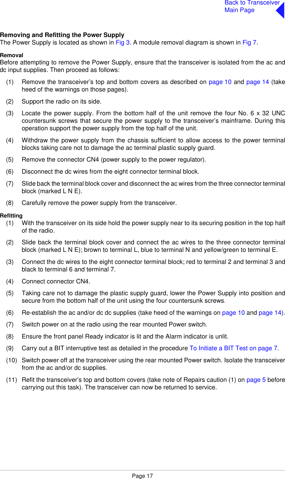
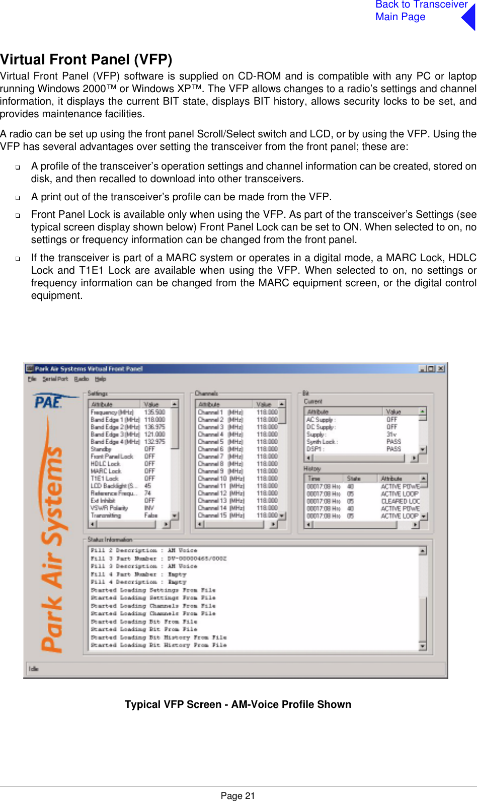
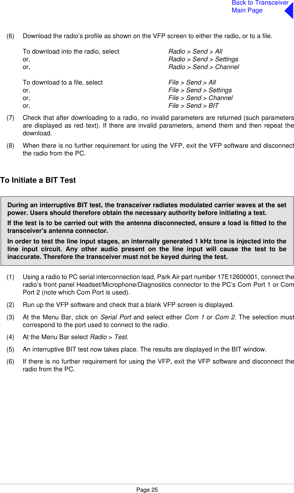
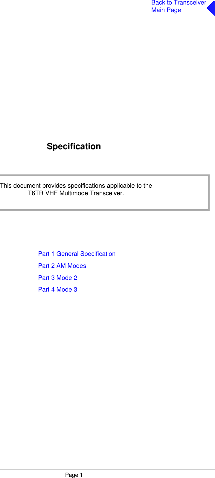
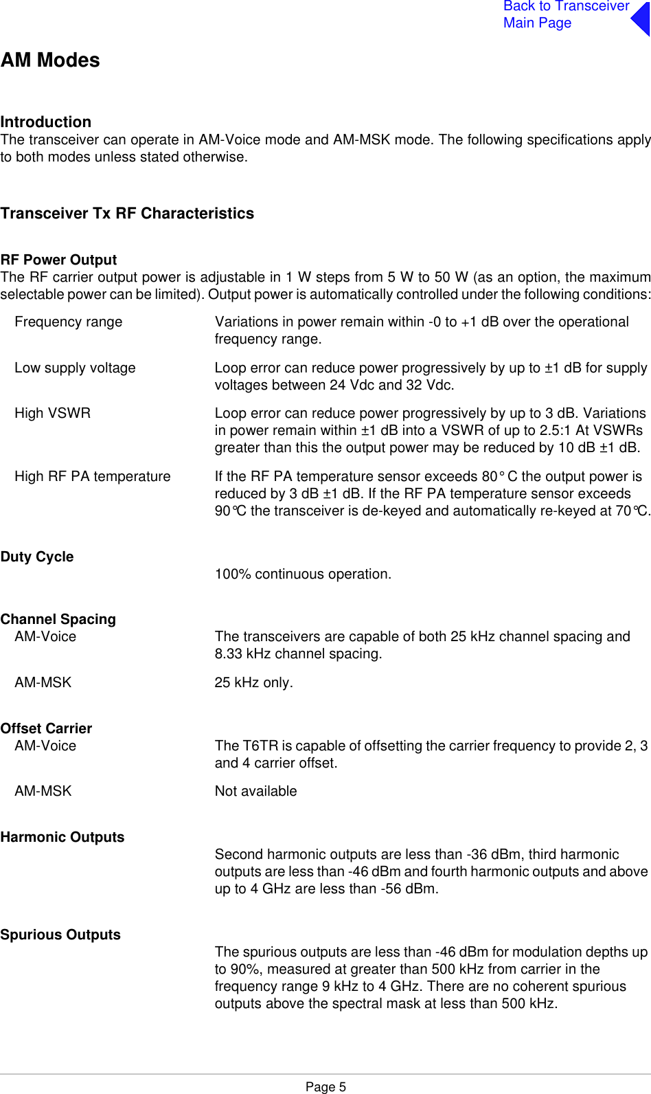
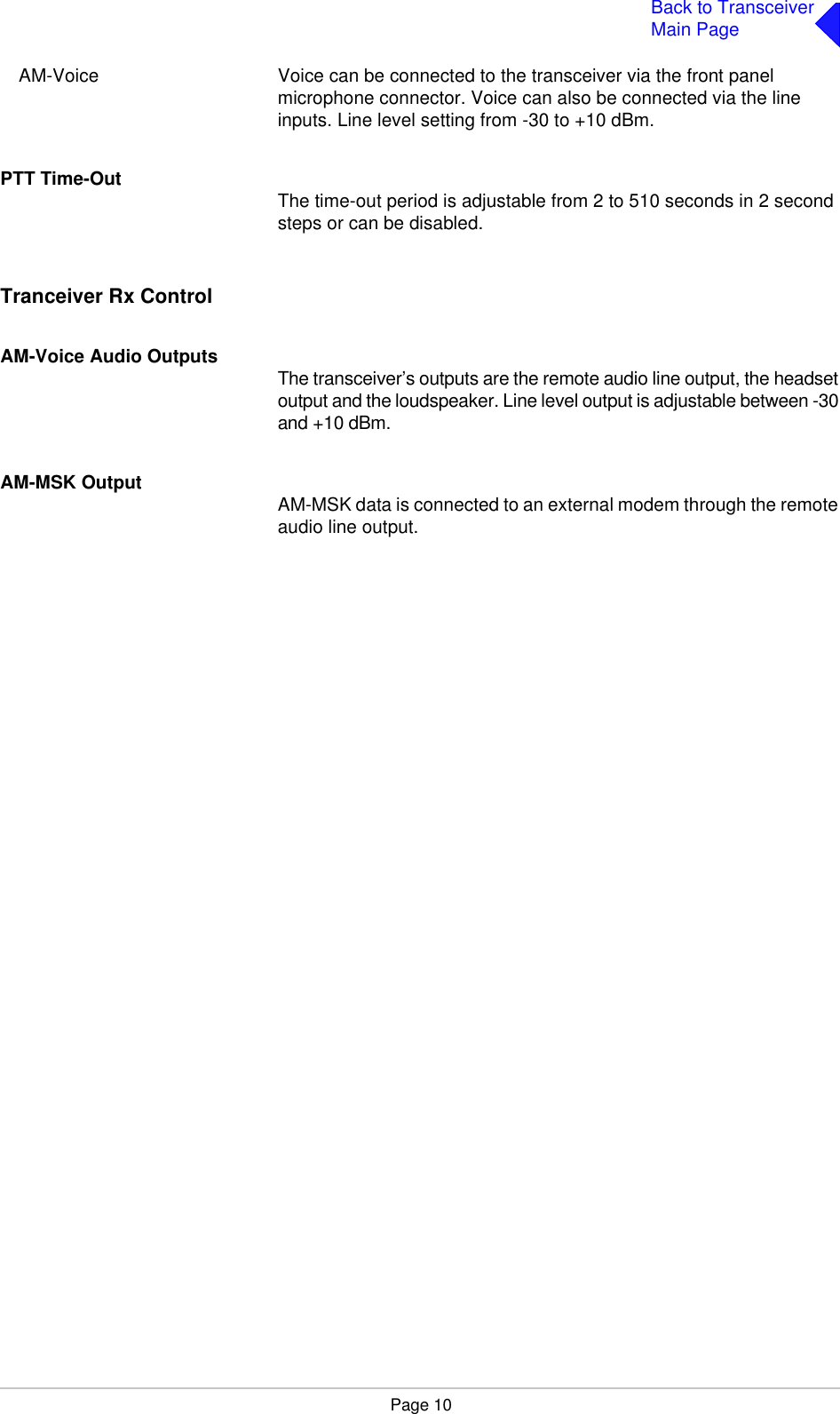
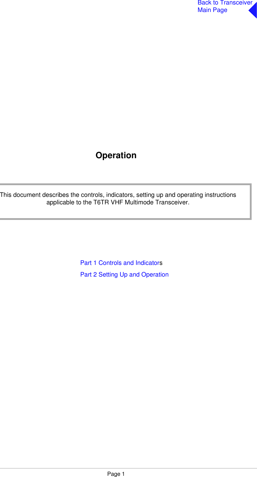
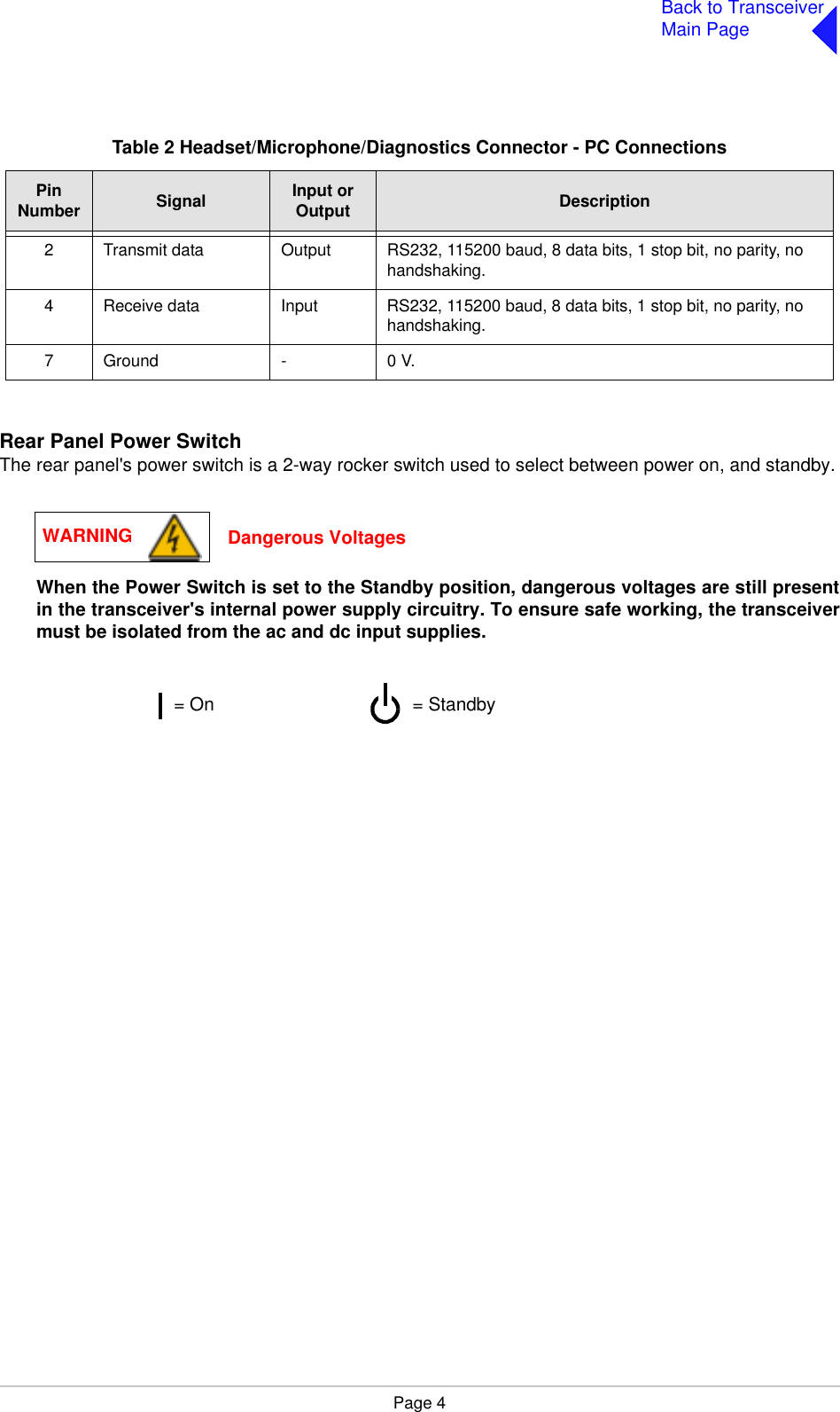
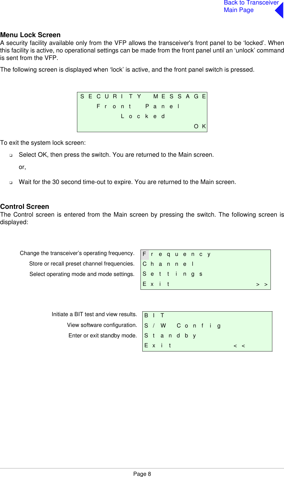
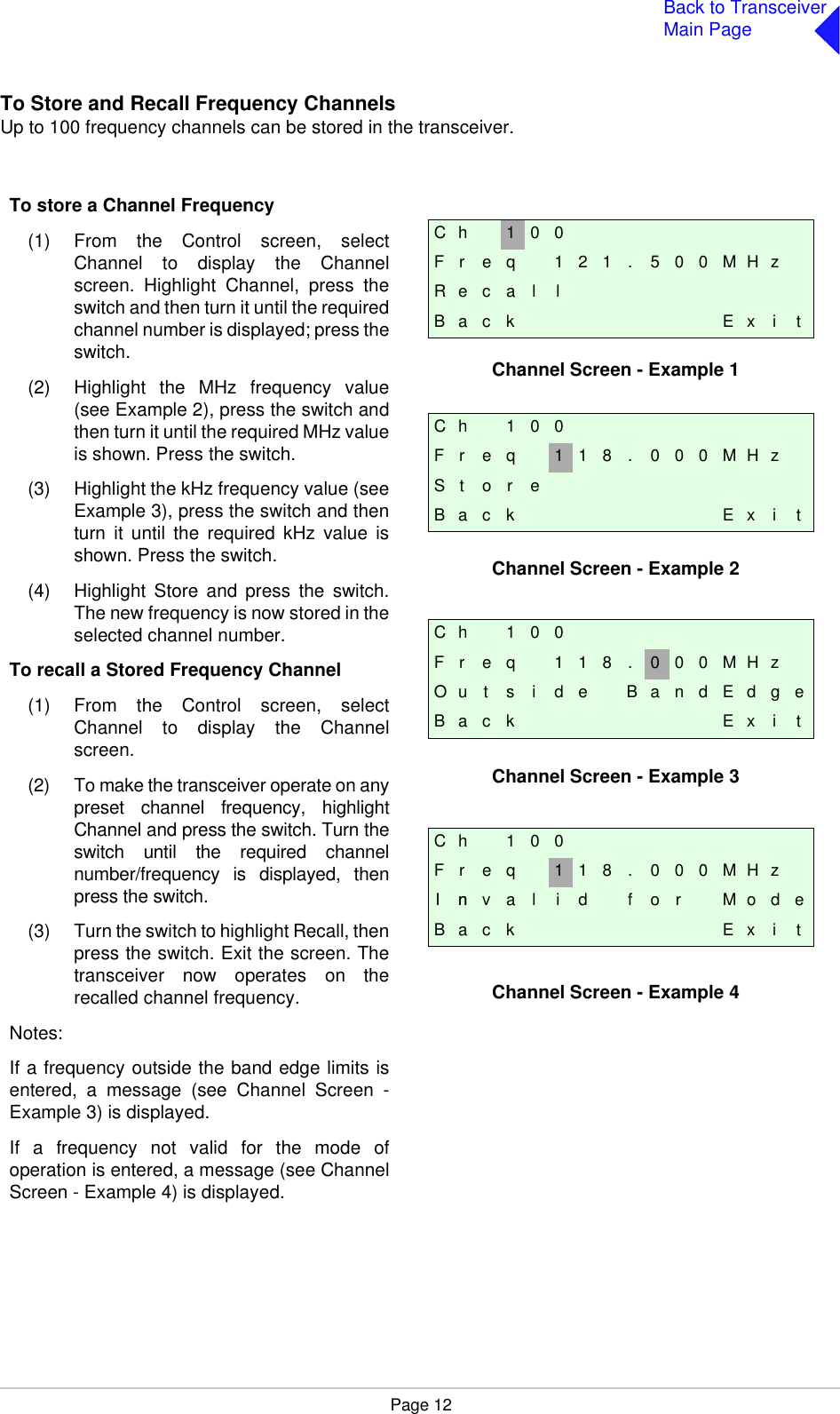
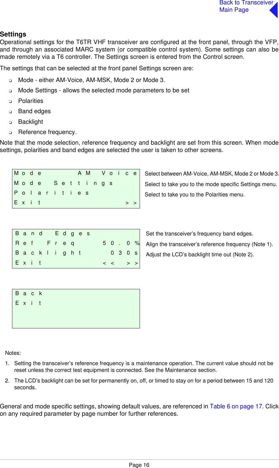
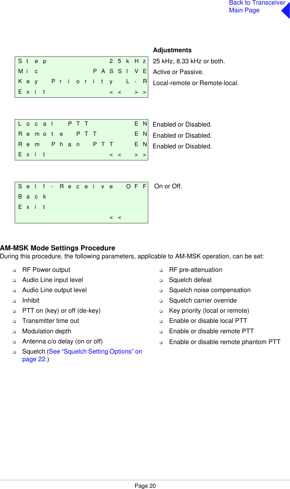
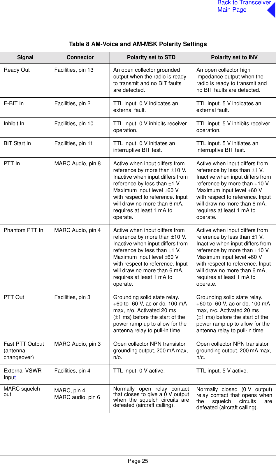
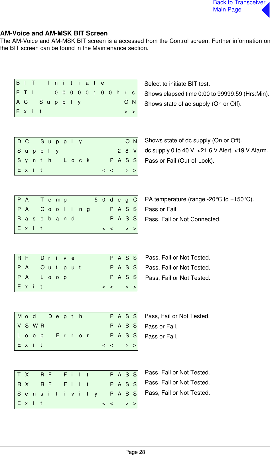
![Page 15Back to TransceiverMain PageRear Panel ConnectorsThe rear panel connectors are shown in Fig 11. These connectors are:Fig 11 Fig 11 Rear Panel (Connectors)The MARC Audio, MARC Data, T1/E1 and HLDC connectors are all RJ48 types. Fig 12 illustrates anRJ48 plug used with these connectors.Fig 12 Fig 12 RJ48 Modular Plug❑Antenna❑RX Antenna❑MARC❑MARC Audio❑MARC Data❑T1/E1❑HLDC❑External Speaker❑Facilities❑ac Supply❑dc Supply( )INTERNALLYSELECTABLERXANTENNAANTENNADANGER HIGHRF VOLTAGESCONNECTANTENNABEFOREUSET1/E1 HDLC MARCDATA MARCAUDIO MARC FACILITIES21.6 - 32V 10APOWER 400VA max~ 110 - 240V ( +10%) 4ASEE INSTALLATION INSTRUCTIONS BEFORECONNECTING SUPPLIESDISCONNECT SUPPLIES WHEN NOT IN USEDC SUPPLYAC SUPPLY48 - 62HzFUSE F1F15A 32V110V - 120V T4A 125V UL110-240V T4A 250V IECRATINGSFUSE F2DC SUPPLYFUSE F2FUSE F1SUPPLYAC SUPPLYRJ48 PlugNumbering is shown as looking from the top of the connector.[The top is being viewed when the lever is on the bottom.]Pin 1](https://usermanual.wiki/Park-Air-Systems/B6550-S2.User-guide/User-Guide-587255-Page-69.png)