Park Air Systems B6550-S2 VHF ground to air transceiver User Manual t6tr
Park Air Systems Limited VHF ground to air transceiver t6tr
Contents
- 1. User guide
- 2. Brochure
User guide
T6TR 50 Watt VHF Multimode Transceiver
Select Topic
Back to
Main Page
MaintenanceInstallationOperationSpecification
This documentation is applicable to transceivers at Mod strike 7
Approvals and
Standards

Back to Transceiver
Main Page
Approvals and Standards T6TR VHF 50 Watt Transceivers
The following standards are applied:
EMC EN 301 489-1; EN 301 489-22.
Health & Safety, EN 60950, CAN/CSA-C22.2 No. 60950, UL 60950.
Radio EN 300 676, IC RSS141, FCC part 15 and 87.
Telecom CS-03.
Approvals:
Standards:
The equipment is designed to meet the essential requirements of Directives
1999/5/EC, 89/336EEC as amended by Directive 93/68/EEC, and 72/23/EEC.
FCC Statement:
This device has been tested and found to comply with the limits for a Class B digital device, pursuant
to part 15 of the FCC Rules. These limits are designed to provide reasonable protection against
harmful interference in a residential installation.
This equipment generates, uses and can radiate radio frequency energy and, if not installed and used
in accordance with the instructions, may cause harmful interference to radio communications.
However, there is no guarantee that interference will not occur in a particular installation.
If this equipment does cause harmful interference to radio or television reception, which can be
determined by turning the equipment off and on, the user is encouraged to try to correct the
interference by one or more of the following measures:
❑Reorient or relocate the receiving antenna.
❑Increase the separation between the equipment and the receiver.
❑Connect the equipment into an outlet on a circuit different from that to which the receiver is
connected.
❑Consult the supplier or an experienced radio/TV technician for help.
Operation on 8.33 kHz channel spacing is restricted to European customers.


Page 2
Back to Transceiver
Main Page
General Specification
The general specification applies to a transceiver irrespective of the selected operating mode. Separate
listings are given for AM modes, Mode 2 and Mode 3.
Frequency Range
The T6TR VHF Multimode Transceiver is available in two variants as listed below:
❑The B6550/NB/50 that operates within the frequency band 118 to 136.975 MHz.
❑The B65500/WB/50 that operates within the frequency band 112 to 155.975 MHz.
Frequency Selectable Band Edges
Four selectable frequency band edges are available on each model:
BE1, BE2, BE3 and BE4. Frequencies can only be selected that lie
between BE1 and BE2 inclusive or between BE3 and BE4 inclusive.
The band edge frequencies can only be set in 25 kHz increments. BE1
and BE3 both default to the lowest selectable frequency for the model
and BE2 and BE4 both default to the highest selectable frequency for
the model.
Frequency Accuracy Better than 1ppm.
Reference Frequency Adjustment
Provision is made on the front panel to allow the 20.95 MHz reference
oscillator frequency to be adjusted. An output is provided suitable for
driving an external frequency counter.
Adjustment allows the frequency to be set to within 0.15 ppm.
Frequency Change Time Less than 250 ms from receipt of a remote frequency change
command message.
Number of Channels The transceiver has a multi-channel capability. 100 channels can be
stored and recalled.
Modulation Modes AM-Voice (standard).
AM-MSK (optional).
Mode 2 (optional).
Mode 3 (optional).

Page 3
Back to Transceiver
Main Page
Power Requirements
The transceiver operates from an ac mains supply, or a dc input supply. When both supplies are
connected, the dc input acts as an automatic backup for the ac mains.
ac input supply The transceiver operates from a 48 to 62 Hz single-phase ac supply
and automatically adjusts to operate from any supply voltage ranging
from 110 Vac to 240 Vac ±10%. The power consumption figures are
given in Table 1.
dc input supply The transceiver operates from a dc input supply between 21.6 and
32 V (measured at the radio’s input). The supply current figures are
given in Table 1.
Dimensions and Weight
The dimensions and weight of the transceiver are:
Width 483 mm (19 inches).
Height 88.9 mm (3.5 inches). The height occupies 2U of equipment cabinet
space.
Depth 430 mm (16.9 inches) measured from front panel to rear panel.
Depth 450 mm (17.8 inches) measured from front panel to rear of fan.
Weight 13.5 kg (29.76 pounds).
Environmental
Temperature range The transceiver operates to specification across the temperature
range of -20 to +55°C.
The transceiver can be stored at temperatures ranging from
-30 to +70°C without causing any damage.
Humidity The transceiver operates to specification at a relative humidity
between 5% and 90% non-condensing.
Altitude The radios operate to specification up to 15,000 feet. Additionally the
equipment is capable of storage at altitudes up to 50,000 feet without
damage.
Shock and vibration The radios comply with shock and vibration protection MIL-STD-810E,
method 516.4, procedure VI - Bench Handling. In all cases, no fixed
parts become loose. No movable part or permanently set adjustment
shifts its setting or position.
Table 1 Power Consumption
Transmitting or
Receiving Requirement Normal Operation
ac dc
Transmitting Typical 300 VA 8.5 A
Maximum 500 VA 12 A
Receiving Typical 70 VA 1.2 A

Page 4
Back to Transceiver
Main Page
Ventilation The transceivers are cooled by an integral fan, which normally runs at
half speed. At an RF PA temperature of 45°C this is increased to full
speed and at 40°C it reduces to half speed again.
The transceivers also include an additional temperature controlled fan
contained in the power supply.
Warm up time All variants are fully operational to specification within 20 seconds
after switch on.

Page 5
Back to Transceiver
Main Page
AM Modes
Introduction
The transceiver can operate in AM-Voice mode and AM-MSK mode. The following specifications apply
to both modes unless stated otherwise.
Transceiver Tx RF Characteristics
RF Power Output
The RF carrier output power is adjustable in 1 W steps from 5 W to 50 W (as an option, the maximum
selectable power can be limited). Output power is automatically controlled under the following conditions:
Frequency range Variations in power remain within -0 to +1 dB over the operational
frequency range.
Low supply voltage Loop error can reduce power progressively by up to ±1 dB for supply
voltages between 24 Vdc and 32 Vdc.
High VSWR Loop error can reduce power progressively by up to 3 dB. Variations
in power remain within ±1 dB into a VSWR of up to 2.5:1 At VSWRs
greater than this the output power may be reduced by 10 dB ±1 dB.
High RF PA temperature If the RF PA temperature sensor exceeds 80° C the output power is
reduced by 3 dB ±1 dB. If the RF PA temperature sensor exceeds
90°C the transceiver is de-keyed and automatically re-keyed at 70°C.
Duty Cycle 100% continuous operation.
Channel Spacing
AM-Voice The transceivers are capable of both 25 kHz channel spacing and
8.33 kHz channel spacing.
AM-MSK 25 kHz only.
Offset Carrier
AM-Voice The T6TR is capable of offsetting the carrier frequency to provide 2, 3
and 4 carrier offset.
AM-MSK Not available
Harmonic Outputs Second harmonic outputs are less than -36 dBm, third harmonic
outputs are less than -46 dBm and fourth harmonic outputs and above
up to 4 GHz are less than -56 dBm.
Spurious Outputs The spurious outputs are less than -46 dBm for modulation depths up
to 90%, measured at greater than 500 kHz from carrier in the
frequency range 9 kHz to 4 GHz. There are no coherent spurious
outputs above the spectral mask at less than 500 kHz.

Page 6
Back to Transceiver
Main Page
Intermodulation Intermodulation products, caused by an interfering signal with the
same power as the transmitter isolated by 30 dB, are at least -40 dBc
at ≥±150 kHz and -50 dBc at ≥±500 kHz.
Transceiver Rx RF Characteristics
Sensitivity
118 to 136.975 MHz 12 dB SINAD for -107 dBm 30% modulated.
112 to 117.975 MHz 12 dB SINAD for -105 dBm 30% modulated
and
137 to 155.975 MHz
Notes ...
(1) All references to SINAD in this document include ITU-T recommendation P.53 weighting.
(2) When operating the transceiver in combined T/R antenna configuration, the sensitivity figures
are degraded by 1 dB.
Channel spacing
AM-Voice mode 25 kHz, or 8.33 kHz.
AM-MSK mode 25 kHz.
IF selectivity
For 25 kHz channel spacing At ±11 kHz from the centre frequency, the signal is attenuated by less
than 6 dB.
At ±25 kHz from the centre frequency, the signal is attenuated by more
than 80 dB.
For 8.33 kHz channel spacing At ±3.5 kHz from the centre frequency, the signal is attenuated by less
than 6 dB.
At ±8.33 kHz from the centre frequency, the signal is attenuated by
more than 70 dB (60 dB using the ETSI test method).
At ±25 kHz from the centre frequency, the signal is attenuated by more
than 80 dB.
Unwanted Signal Suppression
Intermod signal suppression The intermodulation signal suppression is 80 dB or greater (reference
12 dB SINAD) for two unwanted signals spaced 100 kHz
(unmodulated) and 200 kHz (30% modulation) from the channel
frequency.
Blocking ratio 95 dB or greater (reference 12 dB SINAD and degraded by 6 dB) in
the presence of an unmodulated unwanted signal spaced at 200 kHz
from the channel frequency.
105 dB or greater (reference 12 dB SINAD and degraded by 6 dB) in
the presence of an unmodulated unwanted signal spaced at 3 MHz
from the channel frequency.

Page 7
Back to Transceiver
Main Page
Cross-modulation rejection 95 dB or greater (reference 30 dB SINAD and degraded by 10 dB) in
the presence of a 30% modulated unwanted signal spaced at 200 kHz
from the channel frequency.
105 dB or greater (reference 30 dB SINAD and degraded by 10 dB) in
the presence of a 30% modulated unwanted signal spaced at 3 MHz.
Spurious signal suppression 90 dB, or greater (reference 12 dB SINAD) for a 30% modulated
unwanted signal spaced by more than two channels from the tune
frequency up to 1 GHz, 80 dB or greater for frequencies up to 2 GHz
and 70 dB or greater for frequencies above 2 GHz..
Interfering signals At least 6 dB SINAD is achieved for a wanted -87 dBm signal
modulated with a 1 kHz tone 30% in the presence of two -5 dBm
interfering signals, both FM modulated, one with a 19 kHz tone
7.5 kHz deviation at 107.9 MHz and varied by ±4 kHz the other with a
19.1 kHz tone 7.5 kHz deviation with its frequency chosen such that
one of the 3rd order products is located on the chosen receive
frequency.
Antenna radiation Radiation at the antenna socket is less than -81 dBm, typically less
than -100 dBm, within the frequency range 9 kHz to 4 GHz.
Maximum RF Input The transceiver can withstand an RF input of +36 dBm for 20 seconds,
and a continuous +27 dBM input, without causing damage.
Transceiver Tx Modulation Characteristics
The transceiver Tx modulation characteristics are as follows:
Mode
AM-Voice mode The AM-Voice mode uses Double Side Band (DSB) Amplitude
Modulation (AM) full carrier, emission designator 6K80A3EJN for
25 kHz channels and 5K00A3EJN for 8.33 kHz channels.
AM-MSK The AM MSK mode uses Double Side Band (DSB) Amplitude
Modulation (AM) full carrier, emission designator 13K0A2DJN.
Modulation Depth The transceiver is capable of modulation depths up to 95%.
Hum and Noise The hum and noise is more than 45 dB below the signal level for line
input levels <-13 dBm, and more than 50 dB below the signal level for
line input levels ≥−13 dBm, for a carrier modulated by a 1 kHz signal
with a modulation depth of 90%.

Page 8
Back to Transceiver
Main Page
Frequency Response
25 kHz channel spacing The variation in frequency response with reference to a 1 kHz signal
is within +0.5 dB and -1.5 dB across the frequency range 300 to
3400 Hz. The response is also less than -20 dB at 100 Hz and below,
and less than -30 dB at 4 kHz and above.
8.33 kHz channel spacing The variation in frequency response with reference to a 1k Hz signal
is within +0.5 dB and -1.5 dB across the frequency range 350 Hz to
2500 Hz. The response is also less than -10 dB at 100 Hz and below,
and less than -30 dB at 3200 Hz and above.
Distortion
25 kHz channel spacing The total harmonic distortion is less than 5% due to signals with a
modulation depth of 90%, within the frequency range 300 Hz to
3400 Hz.
8.33 kHz channel spacing The total harmonic distortion is less than 5% due to signals with a
modulation depth of 90%, within the frequency range 350 Hz to
2500 Hz.
Residual FM For a test signal of 1 kHz set at 80% modulation depth applied to the
line input of the transceiver, the unwanted peak frequency modulation
does not exceed ±500 Hz.
VOGAD
AM-Voice The VOGAD has an operational range of 30 dB. The VOGAD can be
disabled.
AM-MSK VOGAD permanently disabled.
Mute
AM-Voice The mute level is set at 15 dB below the average speech line level
setting. The mute can be disabled.
AM-MSK The mute is permanently disabled.
Differential group delay
AM-MSK only There is a 60 µs of differential group delay for signals in the range
1200 to 2400 Hz.
Transceiver Rx Modulation Characteristics
The transceiver Rx modulation characteristics are as follows:
Mode
AM-Voice mode The AM-Voice mode uses Double Side Band (DSB) Amplitude
Modulation (AM) full carrier, emission designator 6K80A3EJN for
25 kHz channels and 5K00A3EJN for 8.33 kHz channels.
AM-MSK The AM-MSK mode uses Double Side Band (DSB) Amplitude
Modulation (AM) full carrier, emission designator 13K0A2DJN.

Page 9
Back to Transceiver
Main Page
Frequency response
25 kHz channel spacing The variation in frequency response with reference to a 1 kHz signal,
is within +1 dB and -2 dB across the frequency range 300 to 3400 Hz.
The response is less than -20 dB for frequencies at or below 100 Hz,
and less than -30 dB at 4 kHz and above.
8.33 kHz channel spacing The variation in frequency response with reference to a 1 kHz signal,
is within +1 dB and -2 dB across the frequency range 350 to 2500 Hz.
The response is less than -10 dB for frequencies at or below 100 Hz,
and less than -30 dB at 4 kHz and above.
Distortion
25 kHz channel spacing For RF input signals between -53 dBm and +10 dBm, the total
harmonic distortion is less than 5% within the frequency range 300 Hz
to 3.4 kHz when the modulation depth is between 30 and 90%.
8.33 kHz channel spacing For RF input signals between -53 dBm and +10 dBm, the total
harmonic distortion is less than 5% within the frequency range 350 Hz
to 2.5 kHz when the modulation depth is between 30 and 90%.
Wanted Signal Dynamic Range (RF AGC)
For a 90% modulated on-channel signal, a change in signal level from
-107 dBm to +10 dBm results in less than a 3 dB change in audio
output. On-channel signals modulated at 90% up to a level of
+17 dBm achieve at least 10 dB SINAD.
Audio AGC
AM-Voice Mode The audio AGC compresses a 30% to 90% variation in input
modulation depth to an audio output power change of 1 dB or less.
The audio output level is maintained at the equivalent of 90%
modulation. Audio AGC can be disabled.
AM-MSK Mode The audio AGC is permanently disabled.
Squelch The transceiver has a noise compensated carrier operated squelch
with an adjustment range of -114 to -60 dBm, and providing greater
than 60 dB of quieting. Note that when the RF pre-attenuator is
switched in, the adjustment levels are increased by 6 dB.
The squelch has a noise compensation disable facility to provide
carrier only operation.
Transceiver Tx Control
Transceiver Tx control characteristics are as follows:
Audio Inputs
AM-MSK AM-MSK data is connected to the transceiver via an external modem
connected to the line inputs.

Page 10
Back to Transceiver
Main Page
AM-Voice Voice can be connected to the transceiver via the front panel
microphone connector. Voice can also be connected via the line
inputs. Line level setting from -30 to +10 dBm.
PTT Time-Out The time-out period is adjustable from 2 to 510 seconds in 2 second
steps or can be disabled.
Tranceiver Rx Control
AM-Voice Audio Outputs
The transceiver’s outputs are the remote audio line output, the headset
output and the loudspeaker. Line level output is adjustable between -30
and +10 dBm.
AM-MSK Output AM-MSK data is connected to an external modem through the remote
audio line output.

Page 11
Back to Transceiver
Main Page
Mode 2
Introduction
This section gives the transceiver’s specification applicable to Mode 2 operation. Mode 2 parameters are
identical to AM-Voice mode with the following exceptions:
Transceiver Tx RF Characteristics
RF Power Rise Time The transceiver produces more than 90% of full power output within
the first 2 symbols of the power stabilization segment, which is the first
segment of the training sequence and consists of 4 symbols each
representing 000.
RF Power Decay Time The output power decays by more than 20 dB within 2.5 symbols of
the middle of the final symbol.
Channel Spacing 25 kHz channel spacing only.
Transceiver Tx Modulation Characteristics
Mode Mode 2 uses Carrier Sense Multiple Access (CSMA) differentially
encoded 8-phase shift keying (D8PSK), using a raised cosine filter
with α =0.6 (nominal value), emission designator 14K0G1DE.
Information is differentially encoded with 3 bits per symbol transmitted
as changes in phase rather than absolute phase. The data stream is
divided into groups of 3 consecutive data bits, least significant bit first.
Zeros are padded to the end of transmissions if needed for the final
channel symbol.
Modulation Rate The symbol rate is 10,500 symbols/second (±0.005%), resulting in a
nominal bit rate of 31,500 bits/s.
RMS Phase Error The RMS phase error is less than 3°. The error vector magnitude is
less than 6%.
Phase Acceleration The total frequency change during the transmission of the unique word
is less than 10Hz. After this, the phase acceleration is less than
500 Hz/s.

Page 12
Back to Transceiver
Main Page
Transceiver Rx RF Characteristics
Sensitivity
The transceiver has a sensitivity better than -102dBm for 1x10⁻³ Bit Error Rate (BER) with Reed Solomon
Decoding off.
Channel Spacing Mode 2 channel spacing is 25 kHz.
IF Selectivity At ±11 kHz from the centre frequency, the signal is attenuated by less
than 6 dB.
At ±25 kHz from the centre frequency the signal is rejected by more
than 80 dB.
Unwanted Signal Suppression With the required signal at -92 dBm, a BER of better than 1x10⁻³ with
Reed Solomon Decoding switched off is achieved under the following
conditions:
❑An interfering signal at -32 dBm on an adjacent channel
❑One or more out-of-band interfering signals having a total level of
-33 dBm
❑One or more VHF FM broadcast signals having a total level of
-5 dBm
❑Co-channel rejection better than 20 dB.
Synchronisation For received signals greater than -103 dBm, the probability of
synchronisation is greater than 0.999. The probability of false
synchronisation is 3x10⁻³
Transceiver Rx Modulation Characteristics
Mode 2 uses Carrier Sense Multiple Access (CSMA) differentially
encoded 8-phase shift keying (D8PSK) using a raised cosine filter with
α= 0.6 (nominal value), emission designator 14K0G1DE.
Wanted Signal Dynamic Range (RF AGC)
A BER better than 1x10⁻³ with Reed Solomon Decoding off is
achieved for received signals of -102 dBm to +10 dBm.
Frequency Offsets The transceiver operates with frequency offsets up to 826 Hz.

Page 13
Back to Transceiver
Main Page
Mode 3
Introduction
This section gives the transceiver’s specification applicable to Mode 3 operation. Mode 3 parameters are
identical to AM-Voice mode with the following exceptions:
Transceiver Tx RF Characteristics
RF Power Rise Time The transceiver produces more than 90% of full power output within
the first 2 symbols of the power stabilization segment, which is the first
segment of the training sequence and consists of 4 symbols each
representing 000.
RF Power Decay Time The output power decays by more than 20 dB within 2.5 symbols of
the middle of the final symbol.
Channel Spacing 25 kHz channel spacing only.
Transceiver Tx Modulation Characteristics
Mode Mode 3 uses Time Division Multiple Access (TDMA) differentially
encoded 8-phase shift keying (D8PSK), using a raised cosine filter
with α=0.6 (nominal value), emission designator 14K0G7WET.
Information is differentially encoded with 3 bits per symbol transmitted
as changes in phase rather than absolute phase. The data stream is
divided into groups of 3 consecutive data bits, least significant bit first.
Zeros are padded to the end of transmissions if needed for the final
channel symbol.
Modulation Rate The symbol rate is 10,500 symbols/second (±0.005%), resulting in a
nominal bit rate of 31,500 bits/s.
RMS Phase Error The RMS phase error is less than 3°. The error vector magnitude is
less than 6%.
Phase Acceleration The total frequency change during the transmission of the unique word
is less than 10Hz. After this, the phase acceleration is less than
500 Hz/s.

Page 14
Back to Transceiver
Main Page
Transceiver Rx RF Characteristics
Sensitivity The transceiver has a sensitivity better than -102dBm for 1x10⁻³ Bit
Error Rate (BER) with Reed Solomon Decoding off.
In order to improve co-location performance where maximum
sensitivity cannot be realized due to large unwanted signals, the
transceiver’s sensitivity can be reduced by 6 dB. This is achieved by
switching on the 6 dB RF pre-attenuator from the front panel menu
system.
Channel Spacing Mode 3 channel spacing is 25 kHz.
IF Selectivity At ±11 kHz from the centre frequency, the signal is attenuated by less
than 6 dB.
At ±25 kHz from the centre frequency the signal is rejected by more
than 80 dB.
Unwanted Signal Suppression With the required signal at -92 dBm, a BER of better than 1x10⁻³ with
Reed Solomon Decoding switched off is achieved under the following
conditions:
❑An interfering signal at -32 dBm on an adjacent channel
❑One or more out-of-band interfering signals having a total level of
-33 dBm
❑One or more VHF FM broadcast signals having a total level of
-5 dBm
❑Co-channel rejection better than 20 dB.
Synchronisation For received signals greater than -103 dBm, the probability of
synchronisation is greater than 0.999. The probability of false
synchronisation is 3x10⁻³.
Transceiver Rx Modulation Characteristics
Mode 3 uses Time Division Multiple Access (TDMA) differentially
encoded 8-phase shift keying (D8PSK) using a raised cosine filter with
α= 0.6 (nominal value), emission designator 14K0G7WET.
Wanted Signal Dynamic Range (RF AGC)
A BER better than 1x10⁻³ with Reed Solomon decoding off is achieved
for received signals of -102 dBm to +10 dBm. The AGC attack time is
less than 0.5 ms and the decay time is less than 1 ms for a 40 dB step
input.
Frequency Offsets The transceiver operates with frequency offsets up to 826 Hz.


Page 2
Back to Transceiver
Main Page
Controls and Indicators
This part details the purpose of all controls and indicators of the T6TR transceivers.
Front Panel
The front panel’s controls, indicators and connectors are shown below and detailed in the following
paragraphs.
Scroll/Select Switch and LCD
The Scroll/Select switch is used in conjunction with the LCD to select most of the transceiver's
operational settings. Use of the switch and LCD is fully detailed in the section of this user guide applicable
to the particular operating mode. During normal operation, the LCD shows the operating frequency, the
channel number (if the channel store facility is used), the carrier offset (if used), and displays a graphical
representation of instantaneous peak power.
The example LCD screen below shows the transceiver operating on 118.000 MHz; the frequency has
been preset as channel 100 and offset at +7.3 kHz.
Transmit Indicator
An amber indicator that lights when the transmit circuit is keyed and producing output power.
Receive Indicator
An amber indicator that lights when a signal is received that is above the squelch threshold. Additionally,
this indicator is lit when the transceiver's squelch facility is switched off (squelch defeated). This indicator
also lights when the transceiver is keyed.
Alarm Indicator
A red indicator that either flashes, or lights, when a BIT fault has been detected. BIT indications are
classified as either Alarms or Alerts.
If an ‘alert’ condition is detected, the Alarm indicator flashes, the Ready indicator remains lit, and the
transceiver remains operational. A BIT ‘alert’ is indicated if:
❑If the transceiver RF output power has reduced from its setting by more than 1 dB but not more
than 3 dB
❑If the supply volts falls below a pre-defined level.
Any other BIT condition results in an alarm. When detected, the Alarm indicator lights and the Ready
indicator becomes unlit; the transceiver cannot be used.
READY
ALARM
TRANSMIT
STANDBY SCROLL/
SELECT
REFERENCE
F r e q 1 1 8 .0 0 0 M H z
C h 1 0 0 + 7 . 3 k H z
P w r
Scroll SwitchLCD
M o d e A M V o i c e 1
RECEIVE
HEADSET/
MICROPHONE/
DIAGNOSTICS

Page 3
Back to Transceiver
Main Page
Ready Indicator
A green indicator that lights when the transceiver is ready for use and no BIT faults have been detected.
Standby Indicator
A red indicator that lights when the transceiver is in standby mode. When in standby mode, most of the
radio's circuits are inactive, the front panel LCD is blanked, and the transceiver cannot be keyed.
Standby mode is selected and deselected using the front panel Scroll/Select switch and LCD, by initiating
an instruction through a MARC system, through a T6 controller or through the VFP. For details of front
panel selection and deselection see page 15.
Reference Connector
An SMB jack socket that allows a frequency counter to monitor the transceiver's reference frequency.
This connector is used only for maintenance purposes. The instructions for checking and adjusting the
reference frequency are given in the Maintenance section.
Headset/Microphone/Diagnostics Connector
A dual purpose connector that allows either a headset/microphone, or a PC, to be connected to the
transceiver. The connector is a 7-pin self-locking DIN socket; the pin-out is shown in Table 1.
A microphone is fitted to this connector to enable the transceiver to be operated in AM local mode. The
connections are detailed in Table 1. A PC can also be connected to allow the VFP to be displayed. Using
the VFP is detailed in the T6TR maintenance section. The PC connections at the transceiver are shown
in Table 2 on page 4.
Table 1 Headset/Microphone/Diagnostics Connector - Audio Connections
Pin
Number Signal Input or
Output Description
1 Microphone ground - 0 V.
3 Microphone PTT Input 0 V to PTT.
5 Sidetone/headset drive Output 0 to 3 V pk-pk.
6 Microphone input Input 2 to 35 mV rms on Passive setting and 8 to 140 mV rms
on Active setting to remain in VOGAD range.
7Ground - 0V.
Viewed from front
Page 4
Back to Transceiver
Main Page
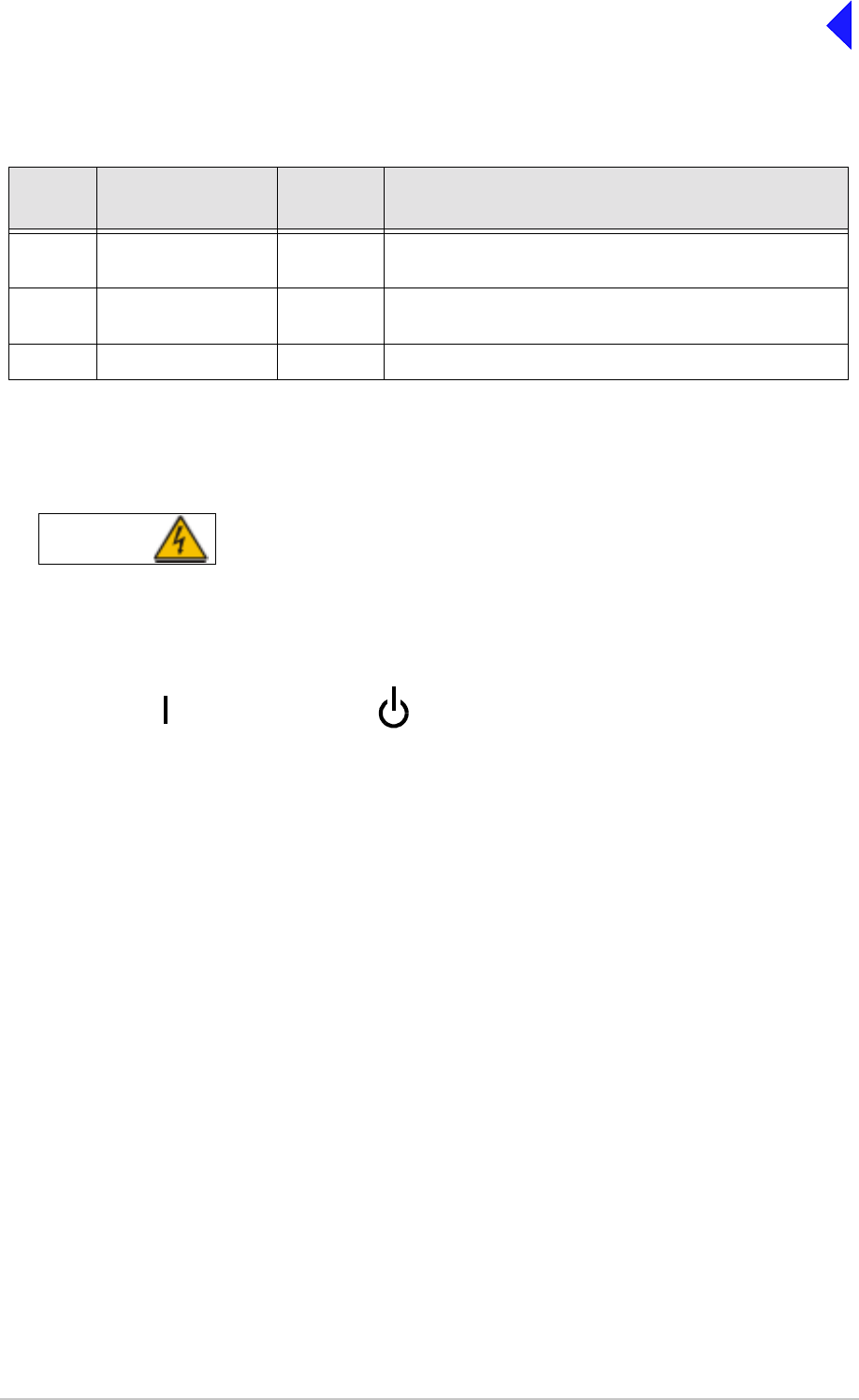
Rear Panel Power Switch
The rear panel's power switch is a 2-way rocker switch used to select between power on, and standby.
When the Power Switch is set to the Standby position, dangerous voltages are still present
in the transceiver's internal power supply circuitry. To ensure safe working, the transceiver
must be isolated from the ac and dc input supplies.
Table 2 Headset/Microphone/Diagnostics Connector - PC Connections
Pin
Number Signal Input or
Output Description
2 Transmit data Output RS232, 115200 baud, 8 data bits, 1 stop bit, no parity, no
handshaking.
4 Receive data Input RS232, 115200 baud, 8 data bits, 1 stop bit, no parity, no
handshaking.
7 Ground - 0 V.
WARNING Dangerous Voltages
= Standby= On

Page 5
Back to Transceiver
Main Page
Setting Up and Operation
Introduction
Setting up the transceiver involves selecting various parameters using the Virtual Front Panel (VFP),
through a Multi-Access Remote Control (MARC) system, from a T6 controller, or from the transceiver’s
front panel. The transceiver can be configured for remote or local use.
Table 11 on page 35 details the functions and parameters that can be set from all these sources.
The rest of this document details how to configure the transceiver from the front panel, and how to
operate the radio in local mode.
Selecting most of the transceiver's operational settings is carried out using the front panel Scroll/Select
switch and the LCD (see the illustration below). No attempt to set up the transceiver should be made until
the transceiver has been installed as per the installation procedures given in the Installation section.
Normal Operation
During normal operation, the LCD displays the Main screen. This screen shows the operating frequency,
the channel number (if the channel store facility is used), the carrier offset (if used), and displays a
graphical representation of output power when the transceiver is keyed. If the transceiver has been set
to Standby mode, which is shown by the front panel Standby Indicator being lit, the LCD is blanked.
Using the Scroll/Select Switch
The Scroll/Select switch (referred to throughout this section as the ‘Switch’) is used to leave the Main
screen and display the Control screen (see page 8). Further use of the Switch displays various selection
menus and allows the required parameters to be set. The switch has three actions: it can be turned
clockwise, anti-clockwise, or momentarily pushed in.
READY
ALARM
TRANSMIT
STANDBY SCROLL/
SELECT
HEADSET/
MICROPHONE/
DIAGNOSTICS
REFERENCE
F r e q 1 1 8 .0 0 0 M H z
C h 1 0 0 + 7 . 3 k H z
P w r
Scroll SwitchLCD
M o d e A M V o i c e 1
RECEIVE

Page 6
Back to Transceiver
Main Page
Screen Protocol
The following protocol is applicable to all screens described in this document.
Main Screen During normal transceiver operation, the Main screen, an example of which is shown
below, is displayed.
Switch Refers to the front panel Scroll/Select switch. The switch is turned clockwise to scroll
through fields from left to right, and from top to bottom. The switch is turned
anti-clockwise to scroll through fields from right to left, and from bottom to top. The
switch is pressed to make a selection.
Time out If during any setting up procedure the Scroll/Select switch is not operated for
30 seconds, the display returns to the Main screen. If editing any parameter has not
been completed, the transceiver stays on the original setting.
>> Indicates more fields are available other than those currently displayed. To access
those fields, turn the switch clockwise through the last displayed field.
<< Indicates more fields are available other than those currently displayed. To access
those fields, turn the switch anti-clockwise through the first displayed field.
Back When Back is selected, you are returned to the previous menu.
Exit When Exit is selected, you are returned to the Main screen.
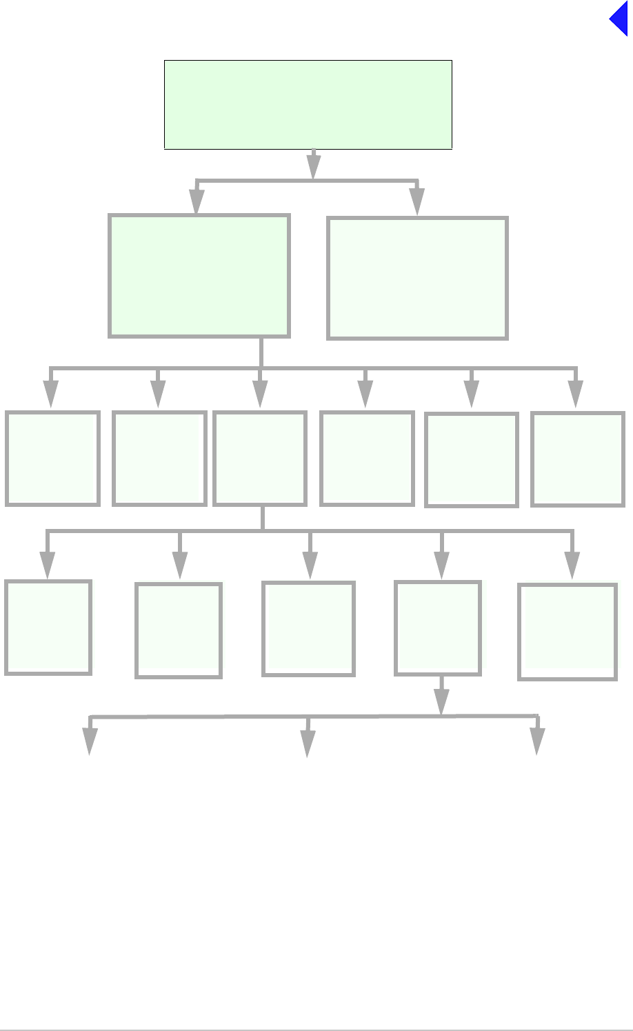
Menu System
The front panel control of the radio is implemented through a hierarchical menu system as shown on the
following page.
F r e q 1 1 8 . 0 0 0 M H z
C h 1 0 0 + 7 . 3 k H z
M o d e A M V o i c e
V o l I I I I I I I I I I
Page 7
Back to Transceiver
Main Page
Menu System
F r e q 1 1 8 . 0 0 0 M H z
C h 1 0 0
M o d e A M V o i c e
V o l I I I I I I I I I I
Settings
Set the
transceiver’s
operational
settings
BIT
Initiate a BIT
test and view
results
Standby
Enter or Exit
standby mode
Ref Freq
Adjust the
transceiver’s
reference
frequency
Band Edges
Set up the
transceiver’s
band edges
Polarities
Set the active
polarity for
certain hardwire
connections
Backlight
Adjust the
display’s
backlight
AM-Voice Mode
Settings
(see page 19)
AM-MSK Mode
Settings
(see page 20)
Digital Modes
(see page 23)
Mode and
Mode
Settings
Select Mode
Menu Lock Screen
(see page 8)
Main Screen
Displayed during normal
transceiver operation
with the transceiver
unkeyed.
Frequency
Set the
transceiver’s
operating
frequency
Channel
Set or recall up
to 100 preset
frequency
channels
Control Screen
Configure the transceiver’s
operating parameters, access
the BIT facility or view the
software configuration.
S/W Config
View the
transceiver’s
software
configuration

Page 8
Back to Transceiver
Main Page
Menu Lock Screen
A security facility available only from the VFP allows the transceiver's front panel to be ‘locked’. When
this facility is active, no operational settings can be made from the front panel until an ‘unlock’ command
is sent from the VFP.
The following screen is displayed when ‘lock’ is active, and the front panel switch is pressed.
To exit the system lock screen:
❑Select OK, then press the switch. You are returned to the Main screen.
or,
❑Wait for the 30 second time-out to expire. You are returned to the Main screen.
Control Screen
The Control screen is entered from the Main screen by pressing the switch. The following screen is
displayed:
S E C U R I T Y M E S S A G E
F r o n t P a n e l
L o c k e d
O K
F r e q u e n c y
C h a n n e l
S e t t i n g s
E x i t > >
B I T
S / W C o n f i g
S t a n d b y
E x i t < <
Change the transceiver’s operating frequency.
Store or recall preset channel frequencies.
Select operating mode and mode settings.
Initiate a BIT test and view results.
View software configuration.
Enter or exit standby mode.

Page 9
Back to Transceiver
Main Page
Notes for Setting Up the Transceiver
The following notes should be read before setting up the transceiver. They advise on the special
frequency display when using 8.33 kHz channel spacing, and give guidance on the optimum line level
settings. Note that for operation in the United States of America, this equipment is certified only for
operation using 25 kHz channel spacing.
Front Panel Display for 25 kHz and 8.33 kHz Channel Spacing
When setting the operating frequency of the transceiver and 8.33 kHz channel spacing is selected, the
displayed frequency differs from the actual channel frequency. Table 3 shows the pattern used for
25 kHz and 8.33 kHz spaced channel frequencies from 118.000 MHz to 118.141 MHz. The pattern is the
same for any frequency within the transceiver's frequency range. The display conforms to ICAO
convention for 8.33 kHz operation.
Input Line Level Settings
The input line level setting displayed on the front panel is equivalent to the average speech level with a
peak-to-average ratio of 13 dB. This corresponds to the level specified for the lines.
When testing the transceiver using a sine wave, the line input level should be set to 10 dB above the line
level setting. The VOGAD and mute thresholds are pre-set at 10 dB and 15 dB respectively below the
line level setting.
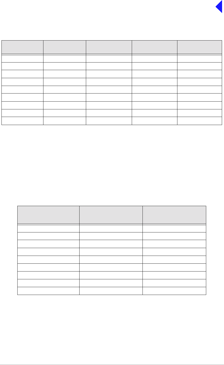
Table 4 shows the relationship between the input line level, VOGAD threshold and mute threshold.
Table 3 25 kHz and 8.33 kHz Channel Spacing Displays
Actual Frequency
(to 4 decimal places) Channel
Spacing Displayed Frequency
at Transceiver's Front Panel
118.0000 MHz
118.0000 MHz
118.0083 MHz
118.0166 MHz
118.0250 MHz
118.0250 MHz
118.0333 MHz
118.0416 MHz
118.0500 MHz
118.0500 MHz
118.0583 MHz
118.0666 MHz
118.0750 MHz
118.0750 MHz
118.0833 MHz
118.0916 MHz
118.1000 MHz
118.1000 MHz
118.1083 MHz
118.1166 MHz
118.1250 MHz
118.1250 MHz
118.1333 MHz
118.1416 MHz
25 kHz
8.33 kHz
8.33 kHz
8.33 kHz
25 kHz
8.33 kHz
8.33 kHz
8.33 kHz
25 kHz
8.33 kHz
8.33 kHz
8.33 kHz
25 kHz
8.33 kHz
8.33 kHz
8.33 kHz
25 kHz
8.33 kHz
8.33 kHz
8.33 kHz
25 kHz
8.33 kHz
8.33 kHz
8.33 kHz
118.000 MHz
118.005 MHz
118.010 MHz
118.015 MHz
118.025 MHz
118.030 MHz
118.035 MHz
118.040 MHz
118.050 MHz
118.055 MHz
118.060 MHz
118.065 MHz
118.075 MHz
118.080 MHz
118.085 MHz
118.090 MHz
118.100 MHz
118.105 MHz
118.110 MHz
118.115 MHz
118.125 MHz
118.130 MHz
118.135 MHz
118.140 MHz
Page 10
Back to Transceiver
Main Page
Output Line Level Setting
The output line level setting displayed on the front panel is equivalent to the average speech level with a
peak-to-average ratio of 13 dB. This corresponds to the level specified for the lines.
When testing the transceiver using a signal generator with sine wave modulation, the line output level
will be 10 dB above the line level setting.
Table 5 shows the relationship between line level, output levels with average speech and sine wave
(assuming that the audio AGC is set to on, and the modulation depth is between 30% and 100%).
Table 4 Relationship Between Line Level, VOGAD Threshold and Mute Threshold
Line Level
Setting (dBm) Average Speech
Level (dBm) Sine Wave Level
(dBm) VOGAD Threshold
(dBm) Mute Threshold
(dBm)
+10 +10 +20 0 -5
+5 +5 +15 -5 -10
00+10-10-15
-5 -5 +5 -15 -20
-10 -10 0 -20 -25
-15 -15 -5 -25 -30
-20 -20 -10 -30 -35
-25 -25 -15 -35 -40
-30 -30 -20 -40 -45
Table 5 Relationship between Line Level, Output Levels with Average Speech
and Sine Wave
Line Level Setting
(Front Panel Setting)
(dBm)
Output Level with
Average Speech
(dBm)
Output Level with
Sine Wave
(dBm)
+10 +10 +20
+5 +5 +15
00+10
-5 -5 +5
-10 -10 0
-15 -15 -5
-20 -20 -10
-25 -25 -15
-30 -30 -20

Page 11
Back to Transceiver
Main Page
Changing the Transceiver’s Operating Frequency
The transceiver’s frequency can be changed in two ways: either from the frequency screen, or by
recalling a preset channel. This procedure details using the Frequency screen.
F r e q 1 1 8 . 0 0 0 M H z
C a n c e l O K
(1) From the Control screen, select
frequency to display the Frequency
screen.
(2) Turn the switch to highlight the digit to
be changed, then press the switch.
(3) Turn the switch until the required digit
is shown, then press the switch.
(4) Repeat until the required frequency is
shown, then highlight OK and press the
switch.

Page 12
Back to Transceiver
Main Page
To Store and Recall Frequency Channels
Up to 100 frequency channels can be stored in the transceiver.
C h 1 0 0
F r e q 1 2 1 . 5 0 0 M H z
R e c a l l
B a c k E x i t
C h 1 0 0
F r e q 1 1 8 . 0 0 0 M H z
S t o r e
B a c k E x i t
C h 1 0 0
F r e q 1 1 8 . 0 0 0 M H z
I nn v a l i d f o r M o d e
B a c k E x i t
C h 1 0 0
F r e q 1 1 8 . 0 0 0 M H z
O u t s i d e B a n d E d g e
B a c k E x i t
To store a Channel Frequency
(1) From the Control screen, select
Channel to display the Channel
screen. Highlight Channel, press the
switch and then turn it until the required
channel number is displayed; press the
switch.
(2) Highlight the MHz frequency value
(see Example 2), press the switch and
then turn it until the required MHz value
is shown. Press the switch.
(3) Highlight the kHz frequency value (see
Example 3), press the switch and then
turn it until the required kHz value is
shown. Press the switch.
(4) Highlight Store and press the switch.
The new frequency is now stored in the
selected channel number.
To recall a Stored Frequency Channel
(1) From the Control screen, select
Channel to display the Channel
screen.
(2) To make the transceiver operate on any
preset channel frequency, highlight
Channel and press the switch. Turn the
switch until the required channel
number/frequency is displayed, then
press the switch.
(3) Turn the switch to highlight Recall, then
press the switch. Exit the screen. The
transceiver now operates on the
recalled channel frequency.
Notes:
If a frequency outside the band edge limits is
entered, a message (see Channel Screen -
Example 3) is displayed.
If a frequency not valid for the mode of
operation is entered, a message (see Channel
Screen - Example 4) is displayed.
Channel Screen - Example 1
Channel Screen - Example 2
Channel Screen - Example 3
Channel Screen - Example 4

Page 13
Back to Transceiver
Main Page
To Initiate a BIT Test
Use the following procedure to initiate an interruptive BIT test from the transceiver's front panel. A BIT
test cannot be initiated while the transceiver is keyed. After a BIT test has been run, the BIT screen is
displayed (see AM-Voice and AM-MSK BIT Screen on page 28). An interruptive BIT test cannot be
initiated in Mode 2 or Mode 3.
(1) From the Main screen, press the switch to display the Control screen. Turn the switch until BIT
is highlighted. Press the switch.
(2) Ensure the BIT menu is displayed. Turn the switch until BIT Initiate is highlighted. Press the
switch.
(3) During the test, which takes approximately two seconds, the Testing screen is displayed.
(4) On completion, and if the interruptive test was initiated from the front panel, one of the following
screens will be shown.
B I T I n i t i a t e
E T I 0 0 0 0 0 : 0 0 h r s
A C S u p p l y O N
E x i t > >
T e s t i n g
P l e a s e W a i t
During an interruptive BIT test, the transceiver radiates modulated carrier waves at the set
power. Users should therefore obtain the necessary authority before initiating a test.
If the test is to be carried out with the antenna disconnected, ensure a load is fitted to the
transceiver's antenna connector.
In order to test the line input stages, an internally generated 1 kHz tone is injected into the
line input circuit. Any other audio present on the line input will cause the test to be
inaccurate. Therefore the transceiver must not be keyed during the test.
B I T
S / W C o n f i g
S t a n d b y
E x i t < <

Page 14
Back to Transceiver
Main Page
(5) Selecting OK takes the user back to the BIT screen.
(6) Selecting OK takes the user back to the BIT screen. The user can then scroll through the screen
to check out transceiver parameters for failure.
T e s t S t a t u s
P A S S
O K
T e s t S t a t u s
F A I L
O K

Page 15
Back to Transceiver
Main Page
Standby Mode
Standby mode is a power saving feature that can be used for non-operational transceivers. When in
standby mode, most of the transceiver's circuits are inactive, the LCD is blanked, and the transceiver
cannot be keyed. To put the transceiver into standby mode, use the following procedure.
When the transceiver is in Standby mode, the red front panel Standby indicator is lit.
To Enter Standby Mode
To Exit Standby Mode
E n t e r S t a n d b y ?
Y e s N o
(1) From the Control screen select
Standby.
(2) At the Standby screen, select Yes.
(3) Check that the display blanks and
the front panel Standby indicator is
lit.
E x i t S t a n d b y ?
Y e s N o
(1) Press the Switch.
(2) Select Yes.
(3) Check that the Main screen is
displayed and that the front panel
Standby indicator is unlit.

Page 16
Back to Transceiver
Main Page
Settings
Operational settings for the T6TR VHF transceiver are configured at the front panel, through the VFP,
and through an associated MARC system (or compatible control system). Some settings can also be
made remotely via a T6 controller. The Settings screen is entered from the Control screen.
The settings that can be selected at the front panel Settings screen are:
❑Mode - either AM-Voice, AM-MSK, Mode 2 or Mode 3.
❑Mode Settings - allows the selected mode parameters to be set
❑Polarities
❑Band edges
❑Backlight
❑Reference frequency.
Note that the mode selection, reference frequency and backlight are set from this screen. When mode
settings, polarities and band edges are selected the user is taken to other screens.
General and mode specific settings, showing default values, are referenced in Table 6 on page 17. Click
on any required parameter by page number for further references.
M o d e A M V o i c e
M o d e S e t t i n g s
P o l a r i t i e s
E x i t > >
B a n d E d g e s
R e f F r e q 5 0 . 0 %
B a c k l i g h t 0 3 0 s
E x i t < < > >
B a c k
E x i t
Select between AM-Voice, AM-MSK, Mode 2 or Mode 3.
Select to take you to the mode specific Settings menu.
Select to take you to the Polarities menu.
Set the transceiver’s frequency band edges.
Align the transceiver’s reference frequency (Note 1).
Adjust the LCD’s backlight time out (Note 2).
Notes:
1. Setting the transceiver’s reference frequency is a maintenance operation. The current value should not be
reset unless the correct test equipment is connected. See the Maintenance section.
2. The LCD’s backlight can be set for permanently on, off, or timed to stay on for a period between 15 and 120
seconds.

Page 17
Back to Transceiver
Main Page
Table 6 Operational Settings from the Front Panel
Parameter Mode Adjustment Range Factory Default Setting Further
Reference
Menu lock screen All Locked or unlocked Unlocked page 8
Enter standby mode All Yes or No - page 15
Exit standby mode All Yes or No - page 15
Set mode of
operation All AM-voice, AM-MSK,
Mode 2 or Mode 3 AM-voice page 16
Set polarities AM-Voice
AM-MSK STD or INV STD page 24
Band edges All
AM modes only
NB model
118.000 to 136.975 MHz
or
WB model
112.000 to 155.975 MHz
NB model
118.000 and 136.975 MHz
WB model
112.000 and 155.975 MHz
page 33
LCD backlight All 15 to 120 s, On or Off 30 s page 16
RF Power All 5 to 50 W 50 W page 19
Audio line in level AM-Voice
AM-MSK -30 to +10 dBm -13 dBm page 19 and
page 21
Audio line out level AM-Voice
AM-MSK -30 to +10 dBm -13 dBm page 19 and
page 21
Inhibit AM-Voice
AM-MSK On or Off Off page 19 and
page 21
PTT (key) AM-Voice
AM-MSK On (key), Off (de-key) Off page 19 and
page 21
Tx time out AM-Voice
AM-MSK 2 to 510 s or Off 180 s page 19 and
page 21
Modulation depth AM-Voice
AM-MSK 5 to 95% 85% page 19 and
page 21
Mute AM-Voice On or Off On page 19
VOGAD AM-Voice On or Off On page 19
Antenna C/O delay AM-Voice
AM-MSK
On or Off On
Off
page 19
page 21
Offset AM-Voice 0, ±2.5, ±5, ±7.3, or
±7.5 kHz 0 (No offset) page 19
Squelch AM-Voice
AM-MSK -114 to -60 dBm in 1 dB
steps. With the RF
pre-attenuator selected,
the range is -108 to
-54 dBm
-107 dBm page 19 and
page 21
RF Pre-attenuation AM-Voice
AM-MSK On or Off Off page 19 and
page 21
Squelch Defeat AM-Voice
AM-MSK On or Off Off page 19 and
page 21
Squelch noise
compensation AM-Voice
AM-MSK On or Off On page 19 and
page 21
Squelch carrier
override AM-Voice
AM-MSK On or Off Off page 19 and
page 21

Page 18
Back to Transceiver
Main Page
AM-Voice Settings Procedure
During this procedure, the following parameters, applicable to AM-Voice operation, can be set:
Audio AGC AM-Voice On or Off On page 19
Loudspeaker AM-Voice On or Off On page 19
Step AM-Voice 8.33, 25 kHz or both 25 kHz page 20
Mic AM-Voice Active or Passive Passive page 20
Key priority AM-Voice
AM-MSK Local-Remote or
Remote-Local Local-Remote page 20 and
page 21
Local PTT AM-Voice
AM-MSK Enabled or Disabled Enabled page 20 and
page 21
Remote PTT AM-Voice
AM-MSK Enabled or Disabled Enabled page 20 and
page 21
Remote phantom PTT AM-Voice
AM-MSK Enabled or Disabled Enabled page 20 and
page 21
Self receive AM-Voice On or Off Off page 20
❑RF power output
❑Audio Line input level
❑Audio Line output level
❑Inhibit
❑PTT on (key) or off (de-key)
❑Transmitter time out
❑Modulation depth
❑Mute (on or off)
❑VOGAD (on or off)
❑Antenna c/o delay (on or off)
❑Offset
❑Squelch (See “Squelch Setting Options” on
page 22.)
❑RF pre-attenuation (on or off)
❑Squelch defeat (on or off)
❑Squelch noise compensation (on or off)
❑Squelch carrier override (on or off)
❑Audio AGC (on or off)
❑Loudspeaker (on or off)
❑Step (25 kHz or 8.33 kHz)
❑Mic (Passive or Active)
❑Key priority (local or remote)
❑Enable or disable local PTT
❑Enable or disable remote PTT
❑Enable or disable remote phantom PTT
❑Self receive
Table 6 Operational Settings from the Front Panel (Continued)
Parameter Mode Adjustment Range Factory Default Setting Further
Reference

Page 19
Back to Transceiver
Main Page
AM-Voice Mode Settings Screen
The AM-Voice mode setting screen is a accessed from the Settings screen. Use the Scroll/Select switch
to select the parameter, then enter the required setting(s).
P o w e r 5 0 W
L i n e I n - 1 3 d B m
L i n e O u t - 1 3 d B m
E x i t > >
I n h i b i t O F F
P T T O F F
T X T i m e o u t 1 8 0 s
E x i t < < > >
M o d D e p t h 8 5 %
M u t e O N
V O G A D O N
E x i t < < > >
A n t C / O D e l O N
O f f s e t 0 . 0 k H z
S q u e l c h - 1 0 7 d B m
E x i t < < > >
R F P r e - A t t e n O F F
S q l D e f e a t O F F
S q l N / C o m p O N
E x i t < < > >
S q l C a r r O / R O F F
A u d i o A G C O N
S p e a k e r O N
E x i t < < > >
Adjustments
RF power between 5 W to 50 W.
Audio line in level between -30 to +10 dBm.
Audio line out level between -30 to +10 dBm.
On or Off.
On (key), Off (de-key).
2 to 510 s.
5 to 95%.
On or Off.
On or Off.
On or Off.
0, ±2.5, ±5, ±7.3, ±7.5 kHz.
-114 to -60 dBm in 1 dB steps. With the RF
pre-attenuator selected, the range is -108 to
-54 dBm.
On or Off.
On or Off.
On or Off.
On or Off.
On or Off.
On or Off.

Page 20
Back to Transceiver
Main Page
AM-MSK Mode Settings Procedure
During this procedure, the following parameters, applicable to AM-MSK operation, can be set:
❑RF Power output
❑Audio Line input level
❑Audio Line output level
❑Inhibit
❑PTT on (key) or off (de-key)
❑Transmitter time out
❑Modulation depth
❑Antenna c/o delay (on or off)
❑Squelch (See “Squelch Setting Options” on
page 22.)
❑RF pre-attenuation
❑Squelch defeat
❑Squelch noise compensation
❑Squelch carrier override
❑Key priority (local or remote)
❑Enable or disable local PTT
❑Enable or disable remote PTT
❑Enable or disable remote phantom PTT
Adjustments
25 kHz, 8.33 kHz or both.
Active or Passive.
Local-remote or Remote-local.
Enabled or Disabled.
Enabled or Disabled.
Enabled or Disabled.
On or Off.
S t e p 2 5 k H z
M i c P A S S I V E
K e y P r i o r i t y L - R
E x i t < < > >
L o c a l P T T E N
R e m o t e P T T E N
R e m P h a n P T T E N
E x i t < < > >
S e l f - R e c e i v e O F F
B a c k
E x i t
< <

Page 21
Back to Transceiver
Main Page
AM-MSK Mode Settings Screens
The AM-Voice mode setting screen is a accessed from the Settings screen. Use the Scroll/Select switch
to select the parameter, then enter the required setting(s).
P o w e r 5 0 W
L i n e I n - 1 3 d B m
L i n e O u t - 1 3 d B m
E x i t > >
I n h i b i t O F F
P T T O F F
T X T i m e o u t 1 8 0 s
E x i t < < > >
M o d D e p t h 8 5 %
A n t C / O D e l O N
S q u e l c h - 1 0 7 d B m
E x i t < < > >
R F P r e - A t t e n O F F
S q l D e f e a t O F F
S q l N / C o m p O N
E x i t < < > >
S q l C a r r O / R O F F
K e y P r i o r i t y L - R
L o c a l P T T E N
E x i t < < > >
R e m o t e P T T E N
R e m P h a n P T T E N
B a c k
E x i t < <
Adjustments
RF power between 5 W to 50 W.
Audio line in level between -30 to +10 dBm.
Audio line in level between -30 to +10 dBm.
On or Off.
On (key), off (de-key).
2 to 510 s.
5 to 95%.
On or Off.
-114 to -60dBm in 1dB steps. With the RF
pre-attenuator selected, the range is -108 to
-54 dBm.
Off or On.
Off or On.
Off or On.
Off or On.
Local-remote or Remote-local.
Enabled or Disabled.
Enabled or Disabled.
Enabled or Disabled.

Page 22
Back to Transceiver
Main Page
Squelch Setting Options
The transceiver’s squelch facility is configured from the AM-Voice, or AM-MSK Settings screen. The
following fields are applicable to squelch operation.
Sql Defeat. The squelch defeat facility can be set to on or off.
❑When set to on, the squelch facility does not operate.
❑When set to off the transceiver’s squelch facilities are available.
Squelch. The squelch field sets the threshold; the default setting is -107 dBm.
❑During periods of no reception, or when signals weaker than the threshold are
received, the transceiver is muted.
❑When signals stronger than the squelch threshold are received, the squelch circuits
are defeated and reception is heard in the normal way.
Sql N/Comp. This field allows noise compensated squelch to be selected on or off. When this facility
is on, the squelch circuits mute all signals weaker than the threshold, and also mute
signals stronger than the threshold that are excessively noisy.
Sql Carr O/R. The carrier override squelch facility is used in conjunction with the noise compensated
squelch facility. If too many noisy signals are being lost due to noise compensation,
carrier override can be switched on to reduce the squelch threshold by 10 dB. The
default threshold of -107 dBm effectively becomes -97 dBm with carrier override
switched on. All signals stronger than -97 dBm, irrespective of the noise level, are then
heard in the normal way.
Using the RF Pre-Attenuator
Selecting the RF pre-attenuator to On provides a 6 dB reduced sensitivity feature to improve co-location
performance where maximum sensitivity cannot be realised due to large unwanted signals
Table 7 Squelch Facility Settings
Required Squelch Operation Squelch Defeat
Setting Squelch Setting Sql N/Comp
Setting Sql Carr O/R
Setting
No squelch On Any Off Off
Squelch
(without noise compensation) Off Required threshold Off Off
Noise compensated squelch Off Required threshold On Off
Noise compensated squelch
with carrier override squelch Off Required threshold On On

Page 23
Back to Transceiver
Main Page
Mode 2 Settings Screen
This is an advisory screen. Pressing OK returns the user to the Main screen.
Mode3 Settings Screen
This is an advisory screen. Pressing OK returns the user to the Main screen.
M o d e 2 p a r a m e t e r s
a r e s e t v i a t h e
H L D C i n t e r f a c e
O K
M o d e 3 p a r a m e t e r s
a r e s e t v i a t h e
T 1 / E 1 i n t e r f a c e
O K

Page 24
Back to Transceiver
Main Page
Polarities Screens AM-Voice and AM-MSK
A number of remote indication and control signals can be hard-wire connected to the transceiver. The
following paragraphs detail the signals applicable to each operational mode of the transceiver.
The Polarities screen is accessed from the Settings screen.
AM-Voice and AM-MSK Polarity Settings
R e a d y O u t S T D
E - B I T I n S T D
I n h i b i t I n S T D
E x i t > >
B I T S t a r t I n S T D
P T T R e f + 1 4 V
P T T I n S T D
E x i t > >
P h a n P T T I n S T D
P T T O u t S T D
F a s t P T T O u t S T D
E x i t < < > >
E x t V S W R I n S T D
M A R C S q l O u t S T D
F A C S q l O u t S T D
E x i t < < > >
P h a n S q l O u t S T D
S q l D e f I n S T D
B a c k
E x i t < <
Each of thirteen polarity settings applicable to
AM-Voice and AM-MSK can be set to the default
STD (standard) setting or INV (inverted).
The signal connections are shown in Table 8 on
page 25 along with the conditions when STD or
INV is selected.
The settings for the PTT Reference voltage are
also shown in Table 8 on page 25.

Page 25
Back to Transceiver
Main Page
Table 8 AM-Voice and AM-MSK Polarity Settings
Signal Connector Polarity set to STD Polarity set to INV
Ready Out Facilities, pin 13 An open collector grounded
output when the radio is ready
to transmit and no BIT faults
are detected.
An open collector high
impedance output when the
radio is ready to transmit and
no BIT faults are detected.
E-BIT In Facilities, pin 2 TTL input. 0 V indicates an
external fault. TTL input. 5 V indicates an
external fault.
Inhibit In Facilities, pin 10 TTL input. 0 V inhibits receiver
operation. TTL input. 5 V inhibits receiver
operation.
BIT Start In Facilities, pin 11 TTL input. 0 V initiates an
interruptive BIT test. TTL input. 5 V initiates an
interruptive BIT test.
PTT In MARC Audio, pin 8 Active when input differs from
reference by more than ±10 V.
Inactive when input differs from
reference by less than ±1 V.
Maximum input level ±60 V
with respect to reference. Input
will draw no more than 6 mA,
requires at least 1 mA to
operate.
Active when input differs from
reference by less than ±1 V.
Inactive when input differs from
reference by more than +10 V.
Maximum input level +60 V
with respect to reference. Input
will draw no more than 6 mA,
requires at least 1 mA to
operate.
Phantom PTT In MARC Audio, pin 4 Active when input differs from
reference by more than ±10 V.
Inactive when input differs from
reference by less than ±1 V.
Maximum input level ±60 V
with respect to reference. Input
will draw no more than 6 mA,
requires at least 1 mA to
operate.
Active when input differs from
reference by less than ±1 V.
Inactive when input differs from
reference by more than +10 V.
Maximum input level +60 V
with respect to reference. Input
will draw no more than 6 mA,
requires at least 1 mA to
operate.
PTT Out Facilities, pin 3 Grounding solid state relay.
+60 to -60 V, ac or dc, 100 mA
max, n/o. Activated 20 ms
(±1 ms) before the start of the
power ramp up to allow for the
antenna relay to pull-in time.
Grounding solid state relay.
+60 to -60 V, ac or dc, 100 mA
max, n/c. Activated 20 ms
(±1 ms) before the start of the
power ramp up to allow for the
antenna relay to pull-in time.
Fast PTT Output
(antenna
changeover)
MARC Audio, pin 3 Open collector NPN transistor
grounding output, 200 mA max,
n/o.
Open collector NPN transistor
grounding output, 200 mA max,
n/c.
External VSWR
InputFacilities, pin 4 TTL input. 0 V active. TTL input. 5 V active.
MARC squelch
out MARC, pin 4
MARC audio, pin 6
Normally open relay contact
that closes to give a 0 V output
when the squelch circuits are
defeated (aircraft calling).
Normally closed (0 V output)
relay contact that opens when
the squelch circuits are
defeated (aircraft calling).

Page 26
Back to Transceiver
Main Page
FAC squelch out Facilities, pin 5 Normally open relay contact
that closes when the squelch
circuits are defeated (aircraft
calling). The relay contact can
be configured to switch any
potential between -60 V and
+60Vdc.
Normally closed relay contact
that opens when the squelch
circuits are defeated (aircraft
calling). The relay contact can
be configured to switch any
potential between -60 V and
+60Vdc.
Phantom squelch
out MARC, pin 2
MARC audio, pin 1 Phantom Squelch. Normally
open relay contact that closes
to connect a 0 V phantom
potential to the audio lines
when the squelch circuits are
defeated (aircraft calling).
Phantom Squelch. Normally
closed relay contact connecting
a 0 V potential to the audio
lines that opens when the
squelch circuits are defeated
(aircraft calling).
Squelch defeat in Facilities pin 7 TTL input. 0 V switches off the
squelch circuits. TTL input. 5 V switches off the
squelch circuits.
PTT Ref
.
-PTT Ref can be set to +14 V,
0 V or -14 V. PTT state is:
+14 V Ref. key ≤+4 V
≥+24 V
u n k e y + 1 3 t o + 1 5 V
0 V Ref. key ≤-10 V
≥+10 V
unkey -1 V to +1 V
-14 V Ref. key ≤-24 V
≥-4 V
unkey -13 to -15 V
Maximum input level ±60 V
with respect to reference. Input
will draw no more than 6 mA,
and requires at least 1 mA to
operate.
PTT Ref can be set to +14 V,
0 V or -14 V. PTT state is:
+14 V Ref. unkey ≤+4 V
≥+24 V
k ey +1 3 t o + 15 V
0 V Ref. unkey ≤-10 V
≥+10 V
key -1 V to +1 V
-14 V Ref. unkey ≤-24 V
≥-4 V
key -13 to -15 V
Maximum input level ±60 V
with respect to reference. Input
will draw no more than 6 mA,
and requires at least 1 mA to
operate.
Table 8 AM-Voice and AM-MSK Polarity Settings
Signal Connector Polarity set to STD Polarity set to INV

Page 27
Back to Transceiver
Main Page
Mode 2 and Mode 3 Polarity Settings
Table 9 Mode 2 and Mode 3 Polarity Settings
Signal Connector Polarity set to STD Polarity set to INV
Ready Out Facilities, pin 13 An open collector grounded
output when the radio is
ready to transmit and no BIT
faults are detected.
An open collector high impedance
output when the radio is ready to
transmit and no BIT faults are
detected.
E-BIT In Facilities, pin 2 TTL input. 0 V indicates an
external fault. TTL input. 5 V indicates an
external fault.
External
VSWR Input
Facilities, pin 4 TTL input. 0 V active TTL input. 5 V active.
R e a d y O u t S T D
E - B I T I n S T D
E x t V S W R I n S T D
E x i t > >
B a c k
E x i t
< <
Each of the three polarity settings applicable to
Mode 2 and Mode 3 can be set to the default STD
(standard) setting or INV (inverted).
The signal connections are shown in Table 9
along with the conditions when STD or INV is
selected.

Page 28
Back to Transceiver
Main Page
AM-Voice and AM-MSK BIT Screen
The AM-Voice and AM-MSK BIT screen is a accessed from the Control screen. Further information on
the BIT screen can be found in the Maintenance section.
B I T I n i t i a t e
E T I 0 0 0 0 0 : 0 0 h r s
A C S u p p l y O N
E x i t > >
D C S u p p l y O N
S u p p l y 2 8 V
S y n t h L o c k P A S S
E x i t < < > >
P A T e m p 5 0 d e g C
P A C o o l i n g P A S S
B a s e b a n d P A S S
E x i t < < > >
R F D r i v e P A S S
P A O u t p u t P A S S
P A L o o p P A S S
E x i t < < > >
M o d D e p t h P A S S
V S W R P A S S
L o o p E r r o r P A S S
E x i t < < > >
T X R F F i l t P A S S
R X R F F i l t P A S S
S e n s i t i v i t y P A S S
E x i t < < > >
Select to initiate BIT test.
Shows elapsed time 0:00 to 99999:59 (Hrs:Min).
Shows state of ac supply (On or Off).
PA temperature (range -20°C to +150°C).
Pass or Fail.
Pass, Fail or Not Connected.
Pass, Fail or Not Tested.
Pass, Fail or Not Tested.
Pass, Fail or Not Tested.
Shows state of dc supply (On or Off).
dc supply 0 to 40 V, <21.6 V Alert, <19 V Alarm.
Pass or Fail (Out-of-Lock).
Pass, Fail or Not Tested.
Pass or Fail.
Pass or Fail.
Pass, Fail or Not Tested.
Pass, Fail or Not Tested.
Pass, Fail or Not Tested.

Page 29
Back to Transceiver
Main Page
I F F i l t e r s P A S S
A u d i o P A S S
D S P 1 P A S S
E x i t < < > >
D S P 2 P A S S
X i l i n x 1 P A S S
X i l i n x 2 P A S S
E x i t < < > >
E E P R O M P A S S
S t a r t U p P A S S
C a l i b r a t i o n P A S S
E x i t < < > >
U n k e y e d P w r P A S S
E - B I T P A S S
M A R C A C T I V E
E x i t < < > >
H D L C I N A C T I V E
T 1 / E 1 I N A C T I V E
B a c k
E x i t < <
Pass, Fail or Not Tested.
Pass, Fail or Not Tested.
Pass or Fail.
Pass or Fail.
Pass or Fail.
Pass or Fail.
Pass or Fail.
Pass or Fail.
Pass or Fail.
Pass or Fail.
Pass or Fail.
Active or Inactive.
Active or Inactive.
Active or Inactive.

Page 30
Back to Transceiver
Main Page
Mode 2 and Mode 3 BIT Screen
The Mode 2 and Mode 3 BIT screen is accessed from the Control screen.
E T I 0 0 0 0 0 : 0 0 h r s
A C S u p p l y O N
D C S u p p l y O N
E x i t > >
S u p p l y 2 8 V
S y n t h L o c k P A S S
P A T e m p 5 0 d e g C
E x i t < < > >
P A C o o l i n g P A S S
V S W R P A S S
L o o p E r r o r P A S S
E x i t < < > >
D S P 1 P A S S
D S P 2 P A S S
X i l i n x 1 P A S S
E x i t < < > >
X i l i n x 2 P A S S
E E P R O M P A S S
S t a r t U p P A S S
E x i t < < > >
C a l i b r a t i o n P A S S
E - B I T P A S S
M A R C A C T I V E
E x i t < < > >
Shows elapsed time 0:00 to 99999:59 (Hrs:Min).
Shows state of ac supply (On or Off).
On or Off.
Shows value of dc supply.
Pass or Fail.
Indicates the PA temperature.
Pass or Fail.
Pass or Fail.
Pass or Fail.
Pass or Fail.
Pass or Fail.
Pass or Fail.
Pass or Fail.
Pass, Fail or Not Tested.
Pass or Fail.
Pass or Fail.
Pass or Fail.
Active or Inactive.

Page 31
Back to Transceiver
Main Page
H D L C A C T I V E
T 1 / E 1 A C T I V E
B a c k
E x i t < <
Active or Inactive.
Active or Inactive.
Active or Inactive.

Page 32
Back to Transceiver
Main Page
Software Configuration Screens
Software configuration screens are as follows:
T 6 V H F 5 0 W T X
1 1 8 - 1 3 6 . 9 7 5 M H z
E x i t > >
B o o t S o f t w a r e
6 5 - x x x x x x x x / v v
E x i t < < > >
B a s e S o f t w a r e
6 5 - x x x x x x x x / v v
E x i t < < > >
M o d e S o f t w a r e
6 5 - x x x x x x x x / v v
[ D e s c r i p t i o n ]
E x i t < < > >
F i l l 1 S o f t w a r e
6 5 - x x x x x x x x / v v
[ D e s c r i p t i o n ]
E x i t < < > >
F i l l 2 S o f t w a r e
6 5 - x x x x x x x x / v v
[ D e s c r i p t i o n ]
E x i t < < > >
Second line variation for WB radios reads
112-155.975 MHz.
65-xxxxxxxx represents the software part
number and /v v represents its version.
65-xxxxxxxx represents the software part
number and /v v represents its version.
Current mode running. 65-xxxxxxxx
represents the software part number and /v v
represents its version.
65-xxxxxxxx represents the software part
number and /v v represents its version.
65-xxxxxxxx represents the software part
number and /v v represents its version.

Page 33
Back to Transceiver
Main Page
Band Edges
The frequency range of the transceiver is 118 to 136.975 MHz for the B6550/NB version, or 112 to
155.975 MHz for the B6550/WB version.
If required, reception can be limited to either one or two smaller parts of the frequency band by setting
the band edges BE1 to BE4. Reception is possible between BE1 and BE2 frequencies, and frequencies
between BE3 and BE4.
Table 10 Band Edge Values
BE1 BE2 BE3 BE4
B6550/NB set so that the full frequency range can be received. 118.000 136.975 118.000 136.975
B6550/WB set so that the full frequency range can be received. 112.000 155.975 112.000 155.975
Example: Transceiver set to transmit and receive only those
frequencies in the range 120 to 130 MHz. 120.000 130.000 120.000 130.000
Example: Transceiver set to transmit and receive only those
frequencies in the ranges 120 to 125 MHz and 130 to
135 MHz. 120.000 125.000 130.000 135.000
F i l l 3 S o f t w a r e
6 5 - x x x x x x x x / v v
[ D e s c r i p t i o n ]
F i l l 4 S o f t w a r e
6 5 - x x x x x x x x / v v
[ D e s c r i p t i o n ]
65-xxxxxxxx represents the software part
number and /v v represents its version.
65-xxxxxxxx represents the software part
number and /v v represents its version.
B E 1 1 1 8 . 0 0 0 M H z
B E 2 1 3 6 . 9 7 5 M H z
B E 3 1 1 8 . 0 0 0 M H z
E x i t > >
B E 4 1 3 6 . 9 7 5 M H z
E x i t < <
The Band Edge screen is accessed from the
Control screen.
Band edge frequencies can be set only in
increments of 25 kHz.
If the transceiver is required to operate over the
full range, the band edge parameters must be set
to the lowest and highest values in the range (see
Table 10).

Page 34
Back to Transceiver
Main Page
BIT Status Warning Screens
The following shows some example BIT screens. These screens alternate with the Main Screen when
an alert or alarm condition is present. Only the parameters causing the alert or alarm are displayed, and
if both an alert and alarm condition exists simultaneously only the alarm information is displayed. If
multiple parameters are signalling an alert or alarm condition, multiple screens are used to display the
status alternating with the Main Screen.
A L E R T
S u p p l y 2 1 V
A L E R T
R F P o w e r R e d u c e d
L o o p E r r o r
S u p p l y 2 1 V
A L E R T
R F P o w e r R e d u c e d
P A T e m p 8 5 d e g C
A L A R M
S y n t h L o c k F a i l
A L A R M
R F P o w e r R e m o v e d
L o o p E r r o r F A I L
S u p p l y 1 8 V
Alarm indicator flashing
No RF power reduction.
Alarm indicator flashing
RF power reduced between 1 and 3 dB.
Alarm indicator flashing
RF power reduced between 1 and 3 dB.
Alarm indicator on
Synth Lock failure (showing a single cause of
alarm).
Alarm indicator on
RF power shut down (showing multiple causes
of alarm).

Page 35
Back to Transceiver
Main Page
Table 11 Functions and Parameters
Function Front
Panel VFP MARC T6
Controller T1/E1 HDLC Default Setting
FREQUENCY
Change frequency ✔✔✔ ✔ ✔ ✔ 118.000 MHz
FREQUENCY CHANNELS
Store/Recall preset
frequency channels ✔✔✔ ✔ ✗ ✗ -
SETTINGS
Set modulation
mode ✔✔✔ ✔ ✔ ✔ AM-Voice
Radio Settings (AM Modes):
Set RF output power ✔✔✔ ✔ ✔ ✔ 50 W
Set audio input line
level ✔✔✔ ✗ ✔ ✗ -13 dBm
Set audio output line
level ✔✔✔ ✗ ✔ ✗ -13 dBm
Set inhibit on or off ✔✔✔ ✗ ✗ ✗ Off
PTT test facility
on (key) off (de-key) ✔✔
View
only ✗✔✗ Off
Set Tx time out ✔✔✔ ✗ ✔ ✗ 180 s
Set modulation
depth ✔✔✔ ✔ ✔ ✗ 85%
Set mute on or off
(AM-Voice only) ✔✔✔ ✗ ✗ ✗ On
Set VOGAD on
or off
(AM-Voice only)
✔✔✔ ✗ ✗ ✗ On
Set antenna C/O
delay on or off ✔✔✔ ✗ ✗ ✗ AM-Voice - On
AM-MSK - Off
Set frequency offset
(AM-Voice only) ✔✔✔ ✗ ✗ ✗ 0 (No offset)
Squelch Level ✔✔✔ ✔ ✗ ✗ -107 dBm
RF pre-attenuator
On or Off ✔✔✔ ✗ ✗ ✗ Off
Continued >>

Page 36
Back to Transceiver
Main Page
Set squelch defeat
on or off ✔✔✔ ✔ ✗ ✗ Off
Set squelch noise
compensation
on or off
✔✔✔ ✗ ✗ ✗ On
Set squelch carrier
override on or off ✔✔✔ ✗ ✗ ✗ Off
Audio AGC on or off ✔✔✔ ✗ ✗ ✗ On
Loudspeaker
on or off ✔✔
View
state ✗✗✗ On
Set frequency step
size
(AM-Voice only)
✔✔ ✗ ✗ ✗ ✗ 25 kHz
Set microphone type
(active or passive)
(AM-Voice only)
✔✔ ✗ ✗ ✗ ✗ Passive
Set keying priority
(local or remote) ✔✔ ✗ ✗ ✗ ✗ Local-Remote
Enable or disable
local PTT ✔✔ ✗ ✗ ✗ ✗ Enabled
Enable or disable
remote PTT ✔✔ ✗ ✗ ✗ ✗ Enabled
Enable or disable
remote phantom
PTT
✔✔ ✗ ✗ ✗ ✗ Enabled
Self Receive
(transmit audio on
line output)
✔✔ ✗ ✗ ✗ ✗ Off
Radio Settings (Digital Modes):
MAC TM1
(inter access delay) ✗✔✗ ✗ ✗ ✔ 2.5 ms
MAC TM2
(channel busy) ✗✔✗ ✗ ✗ ✔ 60 s
MAC p (persistance) ✗✔✗ ✗ ✗ ✔ 13/256
MAC M1 (maximum
number of access
attempts)
✗✔✗ ✗ ✗ ✔ 135
Continued >>
Table 11 Functions and Parameters (Continued)
Function Front
Panel VFP MARC T6
Controller T1/E1 HDLC Default Setting

Page 37
Back to Transceiver
Main Page
Scramble vector ✗✔✗ ✗ ✗ ✔ 4D4B
19787
Tx enable ✗✔✗ ✗ ✗ ✔ On
Polarities:
Ready out ✔✔
View
state ✗✗✗ STD
Set PTT input
polarity
(AM modes only)
✔✔
View
state ✗✗✗ STD
Set phantom PTT
input polarity
(AM modes only)
✔✔
View
state ✗✗✗ STD
Set PTT reference
voltage
(AM modes only)
✔✔
View
state ✗✗✗ +14 V
Set PTT output
polarity
(AM modes only)
✔✔
View
state ✗✗✗ STD
Set fast PTT
antenna changeover
output polarity
(AM modes only)
✔✔
View
state ✗✗✗ STD
Set external VSWR
input polarity
(All modes)
✔✔
View
state ✗✗✗ STD
Set Inhibit input
polarity
(AM modes only)
✔✔
View
state ✗✗✗ STD
BIT interruptive test
input polarity
(AM modes only)
✔✔
View
state ✗✗✗
STD (active low)
E-bit input polarity
(All modes) ✔✔
View
state ✗✗✗
STD (active low)
Squelch output
polarity at the
MARC connector
✔✔ ✗ ✗ ✗ ✗ STD (n/o)
Continued >>
Table 11 Functions and Parameters (Continued)
Function Front
Panel VFP MARC T6
Controller T1/E1 HDLC Default Setting
Page 38
Back to Transceiver
Main Page
Squelch output
polarity at the
Facilities connector
✔✔ ✗ ✗ ✗ ✗ STD (n/o)
Phantom squelch
output polarity ✔✔ ✗ ✗ ✗ ✗ STD (n/o)
Squelch defeat input
polarity ✔✔ ✗ ✗ ✗ ✗ STD
Band Edges:
Set band edges
✔✔ ✗ ✗ ✗ ✗
118.000 & 136.975 MHz
or
112.000 & 155.975 MHz
Reference Frequency:
Adjust transceiver’s
reference frequency ✔✔ ✗ ✗ ✗ ✗ -
LCD Backlight:
Adjust LCD
backlight ✔✔ ✗ ✗ ✗ ✗ 30 s
BIT:
Initiate BIT
interruptive test ✔✔✔ ✔ ✗ ✗ -
Standby:
Enter and exit
standby facility ✔✔✔ ✔ ✗ ✗ Not in Standby
Software Configuration:
View the
transceiver’s
sofeware
configuration
✔✔ ✗ ✗ ✔ ✔ -
LOCK FACILITIES:
Front panel lock ✗✔✗ ✗ ✗ ✗ Off
MARC lock ✗✔✗ ✗ ✗ ✗ Off
T1/E1 lock ✗✔✗ ✗ ✗ ✗ Off
HDLC lock ✗✔✗ ✗ ✗ ✗ Off
Table 11 Functions and Parameters (Continued)
Function Front
Panel VFP MARC T6
Controller T1/E1 HDLC Default Setting

Page 1
Back to Transceiver
Main Page
Installation Procedures
This document gives the installation procedures applicable to the
T6TR VHF Multimode Transceiver.
Page 2
Back to Transceiver
Main Page
The instructions given in this section involve connecting dangerous voltages to the
transceiver. The instructions detailed in this document must be carried out only by suitably
qualified personnel.
The antenna used with the transceiver must be installed such that the resultant radiated field
strength is below 10 W/m² in areas normally accessible to personnel.
The T6TR transceiver's circuitry contains Electrostatic Sensitive Devices (ESSDs).
Personnel must be aware of the precautions necessary to prevent damage to such devices.
During installation all precautions necessary to prevent ESSD damage must be taken.
Changes or modifications made to this equipment that are not expressly approved by
Park Air, or parties authorized by Park Air, could void the user’s authority to operate the
equipment.
Introduction
The procedures in this document describe how to install a T6TR transceiver. The procedures necessary
during installation are listed in Table 1 and it is recommended that they be completed in the order shown.
Table 1 Installation Procedures
Procedure Reference
1 Perform an initial inspection of the transceiver. see page 4
2 Antenna configuration (if required). see page 4
3 Fit the transceiver into an equipment cabinet. see page 6
4 Connect the remote facilities (as required). see page 7
5 Fit the correct ac input fuse. see page 22
6 Connect the chassis stud to the cabinet or system earth. see page 22
7 Connect the ac supply (if required). see page 22
8 Connect the dc supply (if required). see page 23
WARNING Dangerous Voltages
WARNING Antenna Radiation
WARNING ESSDs
Caution Unauthorized Modifications

Page 3
Back to Transceiver
Main Page
Fuses and Connectors
The following list details the radio’s supply fuses and the connectors. Some of the connectors (depending
on your particular configuration) are required during installation.
Component Type Park Air Part Number
Fuses:
AC input fuse, F2, for 110/120 V input
AC input fuse, F2, for 220/230 V input
T4A, 125V, UL
T4A, 250V, IEC
29C11120102S
29E01120108S
DC input fuse 15A size 0 29-01350201
Connectors:
AC supply connector IEC 20-02030102
DC supply connector XLR3 socket 20-01030106
Antenna connector N-type plug 19-01030301
MARC connector 9-way D-type plug Plug: 20-01090100
Cover: 20-09090101
MARC audio RJ48 plug 20K01080100
MARC data RJ48 plug 20K01080100
Facilities connector 15-way D-type plug Plug: 20-01150100
Cover: 20-09150101
HDLC connector RJ48 plug 20K01080100
T1/E1 connector RJ48 plug 20K01080100
Reference connector BNC to SMB 2 metre long lead 17K11000004
Microphone/Diagnostics connector 7-pin DIN plug to 9-way D-type, radio
to PC interconnection lead 17E12600001
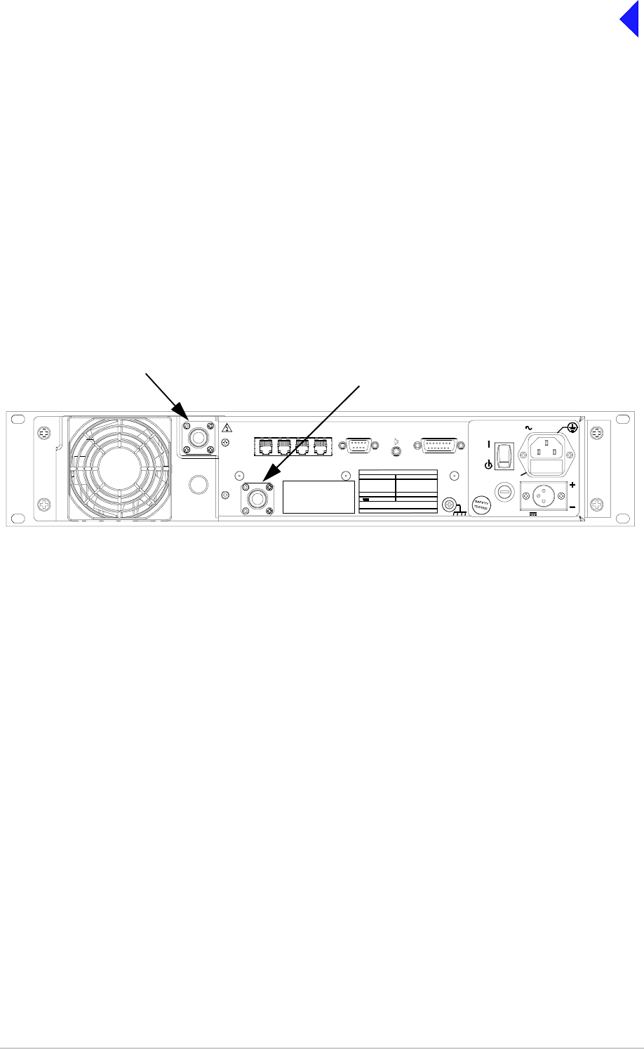
Page 4
Back to Transceiver
Main Page
Initial Inspection of the Transceiver
On receipt of the transceiver from Park Air, remove all transit packaging and check that there is no transit
damage. If damage is evident, contact Park Air immediately and retain the original transit packaging.
The following items are included with the transceiver:
❑Item 1. One copy of the T6 VHF Radios User Guide CD (part number 31-36T62VCD)
❑Item 2. Packing box.
Antenna Configuration
The transceiver can be operated using a single antenna, or separate transmit and receive antennas (see
Fig 4 to Fig 9). For single antenna operation, the antenna’s feeder cable is connected to the rear panel
TX/RX antenna connector. For separate antenna operation, the transmit feeder cable is connected to the
TX/RX antenna connector and the receive feeder cable is connected to the RX antenna connector.
Fig 1 Antennas
Fig 1 Antennas
Internal RF cables must be correctly positioned to suit the required configuration. This is normally carried
out at Park Air prior to shipment. Should the configuration be required to change on installation, perform
the procedure detailed below. Note that if this procedure is used at any other time take note of the
warning preceding the instructions.
( )
INTERNALLY
SELECTABLE
RX
ANTENNA
ANTENNA
DANGER HIGH
RF VOLTAGES
CONNECT
ANTENNA
BEFORE
USE
T1/E1 HDLC MARC
DATA MARC
AUDIO MARC FACILITIES
21.6 - 32 V 10A
POWER 40 0VA max
~ 110 - 240V ( +10%) 4A
SEE INSTALLATION INSTRUCTIONS BEFORE
CONNECTI NG SUPPLIES
DISCON NECT SUPPLI ES WHEN NOT IN USE
DC SUPPLY
AC SUPPLY
48 - 62Hz
FUSE F1
F15A 32V
110V - 120V T4A 125V UL
110- 240V T4A 250V IEC
RATINGS
FUSE F2
DC SUPPLY
FUSE F2
FUSE F1
SUPPLY
AC SUPPLY
RX Antenna
TX/RX Antenna
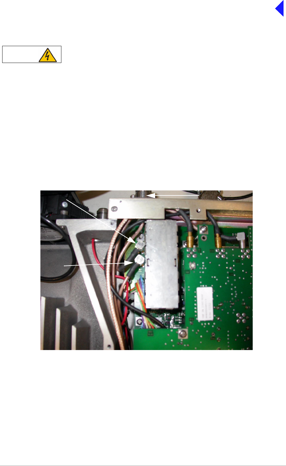
Page 5
Back to Transceiver
Main Page
Changing the Antenna Configuration (if required)
Dangerous voltages are present within the transceiver. Care must be taken by personnel to avoid
accidental contact with exposed circuitry when the bottom cover is removed and power is applied
to the radio
Proceed as follows:
(1) Remove the 15 captive screws securing the bottom cover to the mainframe.
(2) With the cover removed locate the PA Control/Rx RF module.
(3) Locate CN7 and CN12 on the PA Control/Rx RF module (see Fig 2).
(4) For single antenna configuration, connect the Rx antenna RF cable to CN12 (Park). Connect the
adjacent RF cable from the PA module to CN7.
(5) For dual antenna configuration, connect the Rx antenna RF cable to CN7. Connect the adjacent
RF cable from the PA module to CN12 (Park).
Fig 2 Antenna Configuration
Fig 2 Antenna Configuration
(6) When configured, replace the transceiver’s bottom cover using the 15 captive screws.
WARNING Dangerous Voltages
CN7
CN12
RX Antenna
PARK
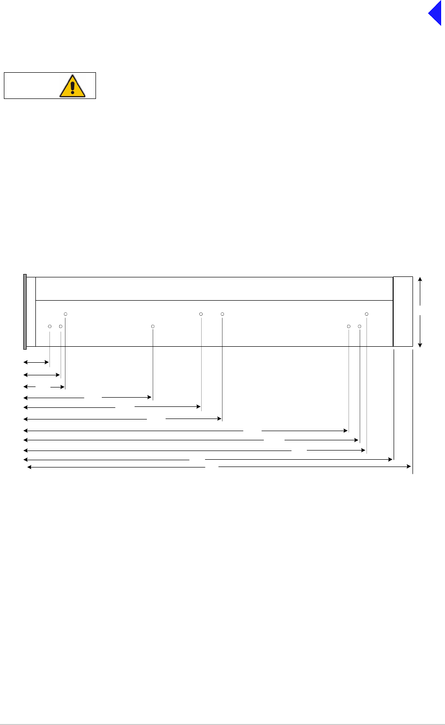
Page 6
Back to Transceiver
Main Page
Fitting a Radio into an Equipment Cabinet
It is essential that the chosen mechanical installation provides adequate support along the
depth (front to rear) of the unit. The transceiver must not be supported by the front panel;
doing so can cause damage.
The transceiver can be installed on telescopic slides, or on fixed runners, within a standard 483 mm
(19 inch) equipment rack. M4 tapped holes, each 10 mm deep (see Fig 3) are provided on each side of
the equipment to accept the slides. Details of suitable telescopic slides and fixed runners are available
from Park Air.
When fitted in the rack, the transceiver's front panel must be secured to the cabinet’s chassis using four
M6 x 16 mm screws and plastic washers.
Fig 3 Slide Fittings
Fig 3 Slide Fittings
Caution Mechanical Support
Front
Panel
399
390.9
378.2
232.2
207.5
152.8
47.0
29.0
41.7
430
88.9
450
All measurements in mm
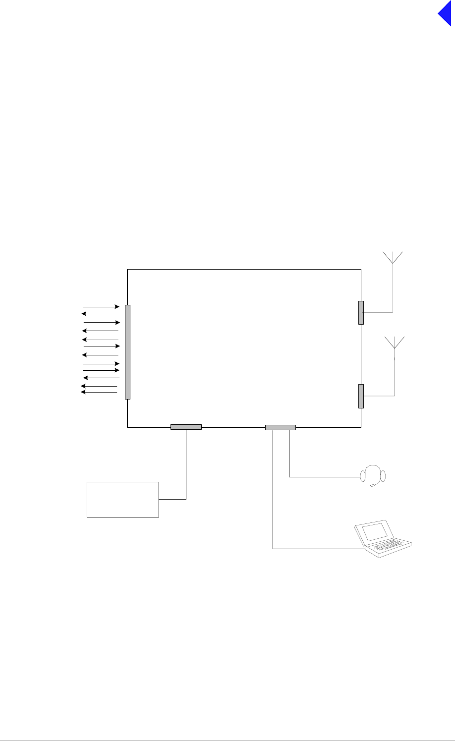
Page 7
Back to Transceiver
Main Page
Connecting the Remote Equipment
Connection of external equipment depends on the configuration required. These configurations are as
follows:
❑T6TR transceiver configured for local operation
❑T6TR transceiver configured for remote operation
❑T6TR transceiver configured for use with MARC
❑T6TR Mode 2 configuration
❑T6TR Mode 3 configuration.
Fig 4 to Fig 9 illustrate the various configurations.
Fig 4
Fig 4 Transceiver Configured for Local Operation
TX/RX Antenna
Connector
Reference
Connector Headset/Microphone/Diagnostics
Connector
Frequency Counter
required only for
maintenance
Facilities
Connector
Mic/Headset for local operation
Laptop (or PC) required
o
nly for maintenance
E-BIT
PTT relay
External VSWR
Squelch
Squelch common
Squelch defeat
Unregulated supply
Inhibit
BIT interruptive test
RSSI
Ready
Tape
T6T Transceiver
RX Antenna
Connector
Either a common Tx/Rx
antenna or separate Tx
and Rx antennas can be
used
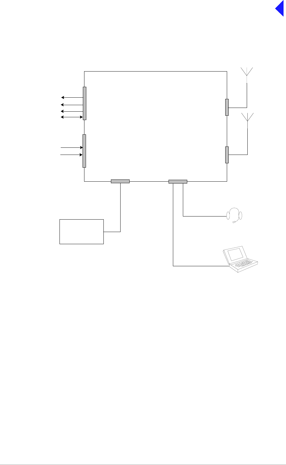
Page 8
Back to Transceiver
Main Page
Fig 5
Fig 5 T6TR Transceiver Configured for Remote Operation
TX/RX Antenna
Connector
Reference
Connector Mic/Headset/Diagnostics
Connector
Frequency Counter
required only for
maintenance
MARC
Connector
Mic/Headset for engineering use
Laptop (or PC) required
only for maintenance
T6T Transceiver
Rx Audio
RS 422 Data
Squelch
Unregulated supply
Note:
The unregulated supply and RS422
data connections may be used when
connecting to remote controllers
such as the Park Air T6 controller
MARC Audio
Connector
Tx Audio
PTT RX Antenna
Connector
Either a common Tx/Rx
antenna or separate Tx and
Rx antennas can be used
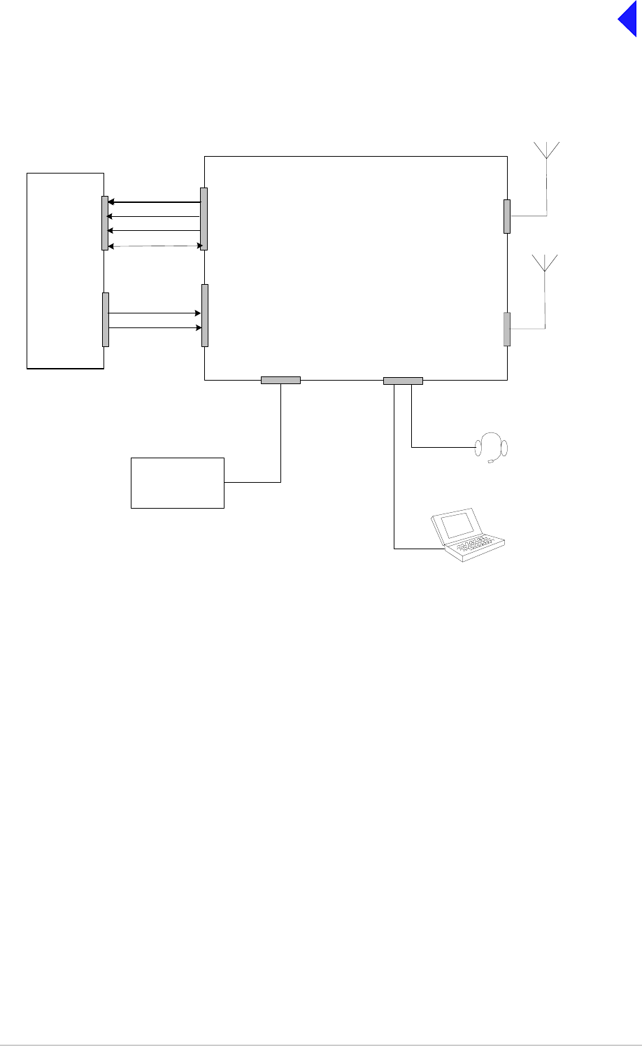
Page 9
Back to Transceiver
Main Page
Fig 6
Fig 6 T6TR Transceiver Configured for use with MARC
TX/RX Antenna
Connector
Reference
Connector Headset/Microphone/Diagnostics
Connector
Frequency Counter
required only for
maintenance
MARC
Connector
Mic/Headset for engineering use
Laptop (or PC) required
only for maintenance
T6TR Transceiver
Equipment
Connector 1
Rx Audio
Squelch
RS422 data
Unregulated supply
RSE2
MARC Audio
Connector
Equipment
Connector 3
Tx Audio
PTT RX Antenna
Connector
Shows single channel connections at RSE2
Either a common Tx/Rx antenna or
separate Tx and Rx antennas can be
used
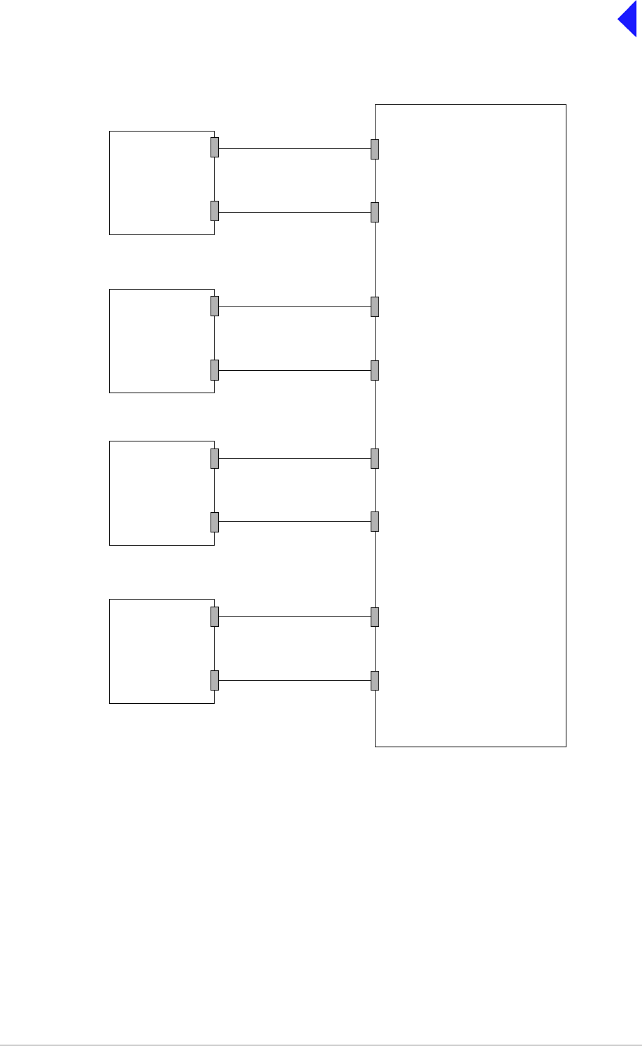
Page 10
Back to Transceiver
Main Page
Fig 7
Fig 7 Transceiver to MARC RSE2 Connections
Fig 7 shows the connection convention when connecting transceivers to a single RSE2. Table 2 and
Table 3 detail the pin to pin connections.
T6TR
Transceiver
MARC
Connector
MARC Audio
Connector
T6TR
Transceiver
MARC
Connector
MARC Audio
Connector
T6TR
Transceiver
MARC
Connector
MARC Audio
Connector
T6TR
Transceiver
MARC
Connector
MARC Audio
Connector
RSE2
Equipment Connector 1
Equipment Connector 3
Equipment Connector 2
Equipment Connector 4
Equipment Connector 5
Equipment Connector 7
Equipment Connector 6
Equipment Connector 8
Receive lines + data
Transmit lines
Receive lines + data
Receive lines + data
Receive lines + data
Transmit lines
Transmit lines
Transmit lines
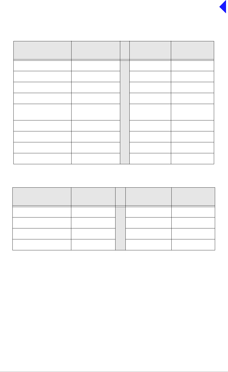
Page 11
Back to Transceiver
Main Page
Table 2 Transceiver to RSE2 Equipment Connector 1, 2, 5 or 6
Transceiver MARC
9-Way D-type Connector
Pin Number
Signal at
Transceiver Signal at RSE2 RSE2 Equipment
Connector Pin
Number
1Ground Ground 1
2 Audio line out (+) Audio line L1 2
3 Audio line out (-) Audio line L2 3
4 Squelch indication Mute indication 4
5 Unregulated supply
output Unregulated
supply input 5
6Data in (+) Data out (+) 6
7 Data in (-) Data out (-) 7
8 Data out (+) Data in (+) 8
9 Data out (-) Data in (-) 9
Table 3 Transceiver to RSE2 Equipment Connector 3, 4, 7 or 8
Transceiver MARC RJ48
Audio Connector Pin
Number
Signal at
Transceiver Signal at RSE2 RSE2 Equipment
Connector Pin
Number
7 Ground Ground 1
4 Audio line in (+) Audio line L1 2
5 Audio line in (-) Audio line L2 3
8PTT PTT 4
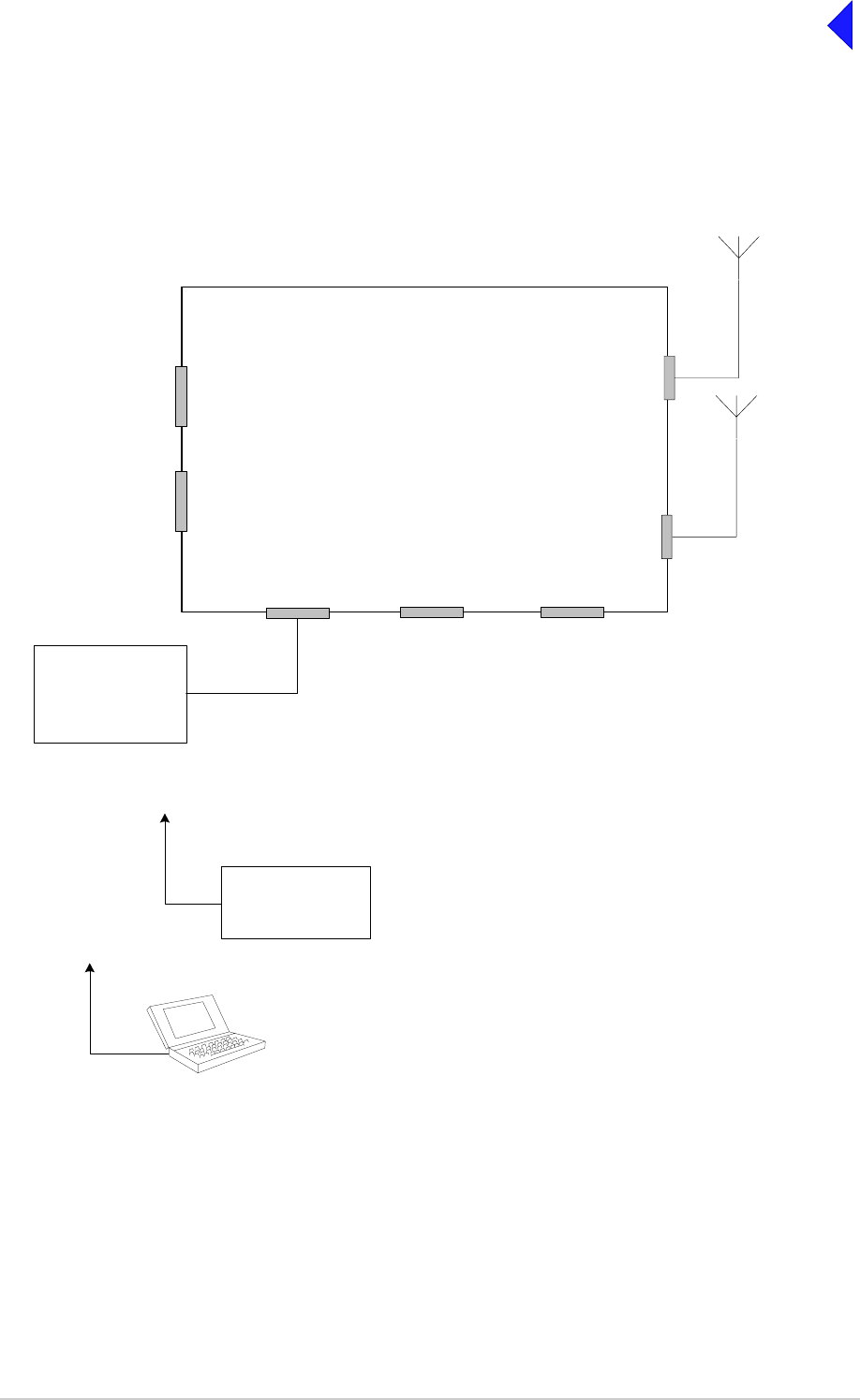
Page 12
Back to Transceiver
Main Page
Fig 8
Fig 8 T6TR Mode 2 Configuration
TX/RX Antenna
Connector
T6TR Transceiver
HDLC
Connector T1/E1
Connector Facilities
Connector
Reference
Connector
Headset/Microphone/Diagnostics
Connector
Mode 2
Network Computer
Connects to the
eadset/Diagnostics
connector
Frequency Counter
required only for
maintenance
Connects to the
Reference connector
Control and data
RX Antenna
Connector
Either a common Tx/Rx
antenna or separate Tx
and Rx antennas can
be used
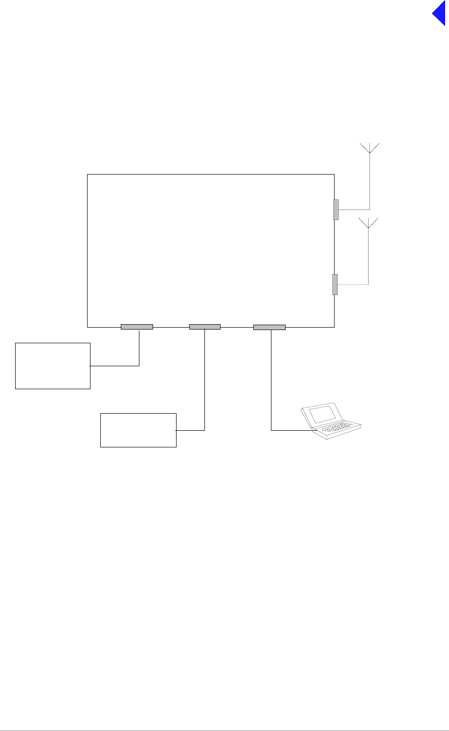
Page 13
Back to Transceiver
Main Page
Fig 9
Fig 9 T6TR Mode 3 Configuration
T6TR Transceiver
T1/E1
Connector Reference
Connector
Mic/Headset/Diagnostics
Connector
Mode 3
Network Computer Control and data
Frequency Counter
required only for
maintenance
Laptop (or PC) required only
for maintenance
TX/RX Antenna
Connector
RX Antenna
Connector
Either a common Tx/Rx antenna or
separate Tx and Rx antennas can be
used
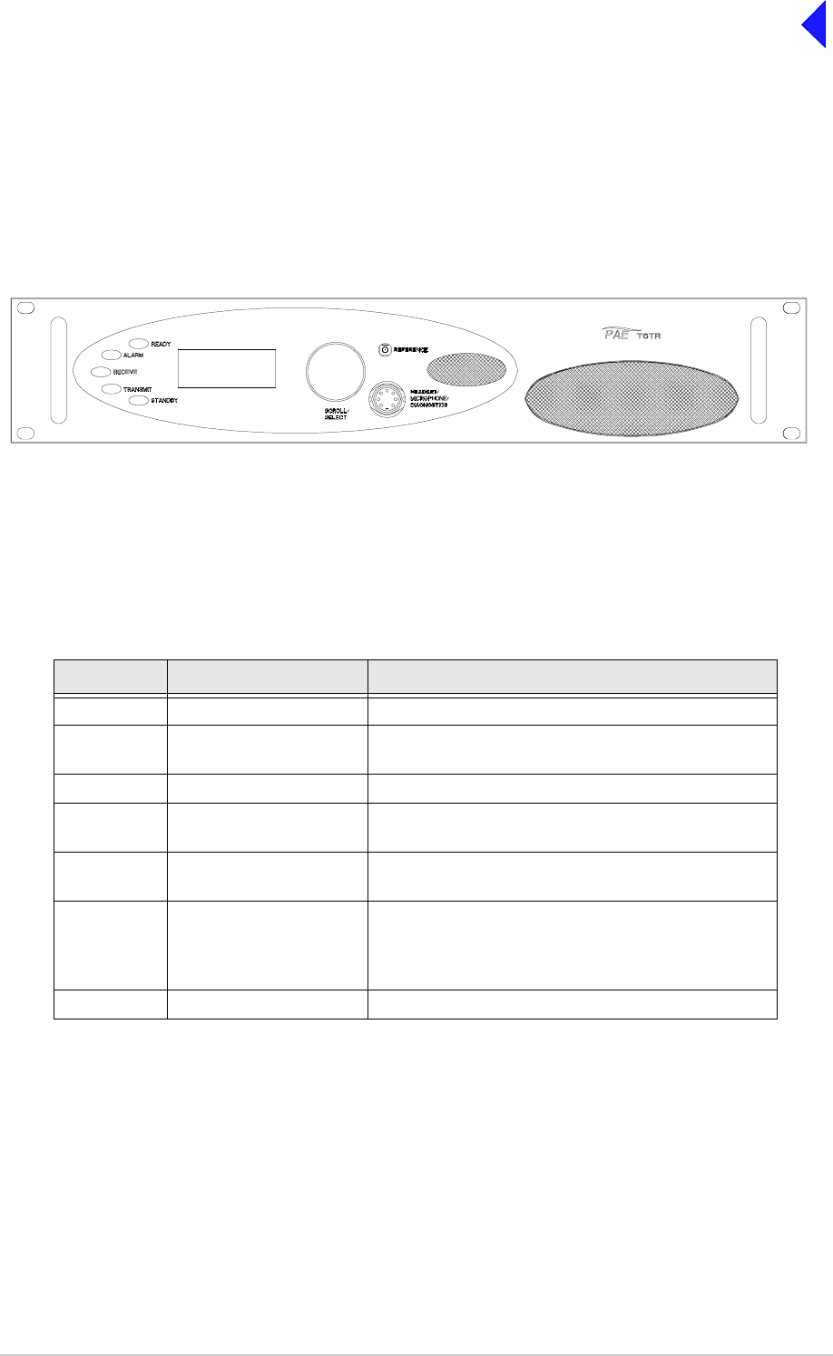
Page 14
Back to Transceiver
Main Page
Connectors
Front and rear panel connector pin-outs are detailed in Table 4 to Table 11. The Reference connector is
described in text.
Front Panel Connectors
The front panel has two connectors; Headset/Microphone/Diagnostics connector and Reference
connector. These are illustrated in Fig 10.
Fig 10
Fig 10 Front Panel
Headset/Microphone/Diagnostics Connector
The Headset/Microphone/Diagnostic connector is shown in Table 4. This connector is a self-locking
7-way DIN socket used for connecting a microphone, microphone/headset or computer.
Reference Connector
The Reference connector is an SMB plug used to monitor the radio’s reference frequency. It monitors
the frequency at a level of 100 mV (±50 mV) with less than -10 dBc harmonics.
Table 4 Headset/Microphone/Diagnostics Connector
Pin Number Signal Characteristic
1 Microphone ground 0 V
2 Transmit data (output) RS232. 115200 baud, 8 data bits, 1 stop bit, no parity,
no handshaking.
3 Microphone PTT (input) 0 V to PTT.
4 Receive data (input) RS232. 115200 baud, 8 data bits, 1 stop bit, no parity,
no handshaking.
5 Sidetone/headset drive
(output) The level is adjustable between 0 and 3 V
peak-to-peak by using the volume control.
6 Microphone input (input) To ensure correct VOGAD operation, the following
microphone input levels are required:
Passive setting: between 2 and 35 mV
Active setting: between 8 and 140 mV
7 Ground 0 V
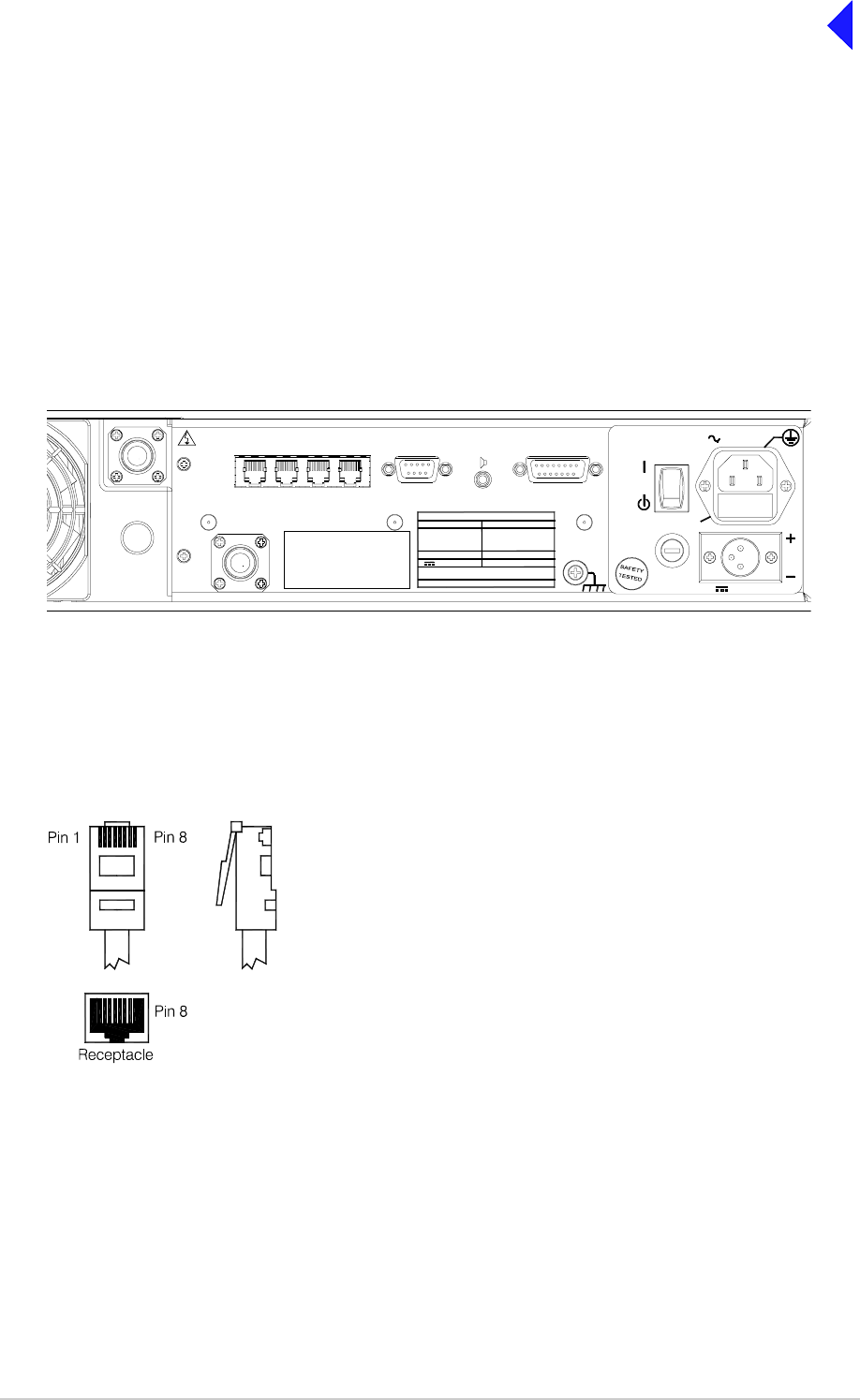
Page 15
Back to Transceiver
Main Page
Rear Panel Connectors
The rear panel connectors are shown in Fig 11. These connectors are:
Fig 11
Fig 11 Rear Panel (Connectors)
The MARC Audio, MARC Data, T1/E1 and HLDC connectors are all RJ48 types. Fig 12 illustrates an
RJ48 plug used with these connectors.
Fig 12
Fig 12 RJ48 Modular Plug
❑Antenna
❑RX Antenna
❑MARC
❑MARC Audio
❑MARC Data
❑T1/E1
❑HLDC
❑External Speaker
❑Facilities
❑ac Supply
❑dc Supply
( )
INTERNALLY
SELECTABLE
RX
ANTENNA
ANTENNA
DANGER HIGH
RF VOLTAGES
CONNECT
ANTENNA
BEFORE
USE
T1/E1 HDLC MARC
DATA MARC
AUDIO MARC FACILITIES
21.6 - 32V 10A
POWER 400VA max
~ 110 - 240V ( +10%) 4A
SEE INSTALLATION INSTRUCTIONS BEFORE
CONNECTING SUPPLIES
DISCONNECT SUPPLIES WHEN NOT IN USE
DC SUPPLY
AC SUPPLY
48 - 62Hz
FUSE F1
F15A 32V
110V - 120V T4A 125V UL
110-240V T4A 250V IEC
RATINGS
FUSE F2
DC SUPPLY
FUSE F2
FUSE F1
SUPPLY
AC SUPPLY
RJ48 Plug
Numbering is shown as looking from the top of the connector.
[The top is being viewed when the lever is on the bottom.]
Pin 1

Page 16
Back to Transceiver
Main Page
Antenna Connectors
The antenna connectors are N-type sockets suitable for connecting 50 ohm antennas.
MARC Connector
The MARC connector is a 9-way D-type socket used for connecting to a MARC system via an RSE2. The
connector pin-out is detailed in Table 5.
Note ...
The line level figures shown for the MARC and MARC Audio connectors are the limits when testing
the transceiver with sine wave modulation; the line level will be 10 dB above the line level setting.
See the information supplied under the heading ‘Line Level Settings’ in the Operation section.
Table 5 MARC Connector
Pin Number Signal Characteristic
1 Ground 0 V
2
3
Audio line out (+)
Audio line out (-)
Balanced 600 ohm, -20 to +20 dBm.
Phantom squelch (see Fig 14) - solid-state relay,
+60 to -60 V ac or dc, 100 mA max, configurable n/o or n/c.
Pair to pin 2.
4 Squelch (output) Solid state relay, +60 to -60 V, ac or dc, 100 mA max,
configurable n/o or n/c.
5 Unregulated supply
(output) This output is between 21.6 and 32 Vdc (nominally 24 V)
fused at 500 mA.
6
7
Data in (+)
Data in (-) RS422 differential asynchronous data at 9600 baud. 8 data
bits, 1 stop bit, no parity, no handshaking.
8
9
Data out (+)
Data out (-) RS422 differential asynchronous data at 9600 baud. 8 data
bits, 1 stop bit, no parity, no handshaking.

Page 17
Back to Transceiver
Main Page
MARC Audio Connector
The MARC Audio connector is an 8-way RJ48 socket. The connector pin-out is detailed in Table 6.
Table 6 MARC Audio Connector
Pin Number Signal Characteristic
1
2
Audio line out (-)
Audio line out (+)
Balanced 600 ohm -20 and +20 dBm. Phantom
squelch (see Fig 14) - solid-state relay, +60 to -60 V,
ac or dc, 100 mA max, configurable n/o or n/c.
3 Fast antenna
changeover/PTT Open collector NPN transistor grounding output,
200 mA max, configurable n/o or n/c.
4
5
Audio line in (+)
Audio line in (-)
Balanced 600 ohm input, -20 to +20 dBm.
Phantom PTT (see Fig 13) - active when input differs
from reference by more than ±10 V. Inactive when
input differs from reference by less than ±1 V.
Maximum input level ±60 V with respect to reference.
Input will draw no more than 6 mA, requires at least
1 mA to operate. Configurable active high or low.
Common reference to all inputs programmable to
+14, 0 or -14 V (±1 V).
6 Squelch
(output) Solid state relay, +60 to -60 V, ac or dc, 100 mA max,
configurable n/o or n/c.
7Ground 0 V.
8 PTT (input) Active when input differs from reference by more than
±10 V. Inactive when input differs from reference by
less than ±1 V. Maximum input level ±60 V with
respect to reference. Input will draw no more than
6 mA, requires at least 1 mA to operate. Configurable
active high or low. Common reference to all inputs
programmable to +14, 0 or -14 V (±1 V).
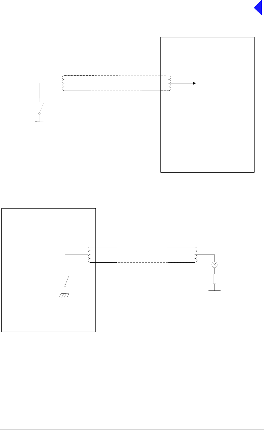
Page 18
Back to Transceiver
Main Page
Fig 13
Fig 13 Example Phantom PTT Keying Diagram
Fig 14
Fig 14 Example Phantom Squelch Indication Diagram
T6TR Transceiver
Audio lines with phantom PTT
signal superimposed
Solid state
relay
Reference can be configured as +14 V, 0 V
or -14 V from the Polarities screen.
With STD selected, PTT active when input
differs from reference by more than ±10 V.
PTT inactive when input differs from
reference by less than ±1 V.
With INV selected, PTT active when input
differs from reference by less than ±1 V. PTT
inactive when input differs from reference by
more than ±10 V.
For example, to use 0 volt as the keying
potential with STD polarity, set the reference
to +14 V or -14 V.
PTT
Maximum signal level ±60 V
with respect to transmitter
reference.
Internal Sensing Circuit
T6TR Transceiver
The pull-up voltage should be in the
range -60 to +60 V ac or dc.
R
Squelch Indicator
Audio lines with phantom
squelch signal superimposed
V
Solid state
relay
Relay = 100 mA maximum.
Can be configured as normally open, or
normally closed from the Polarities screen.
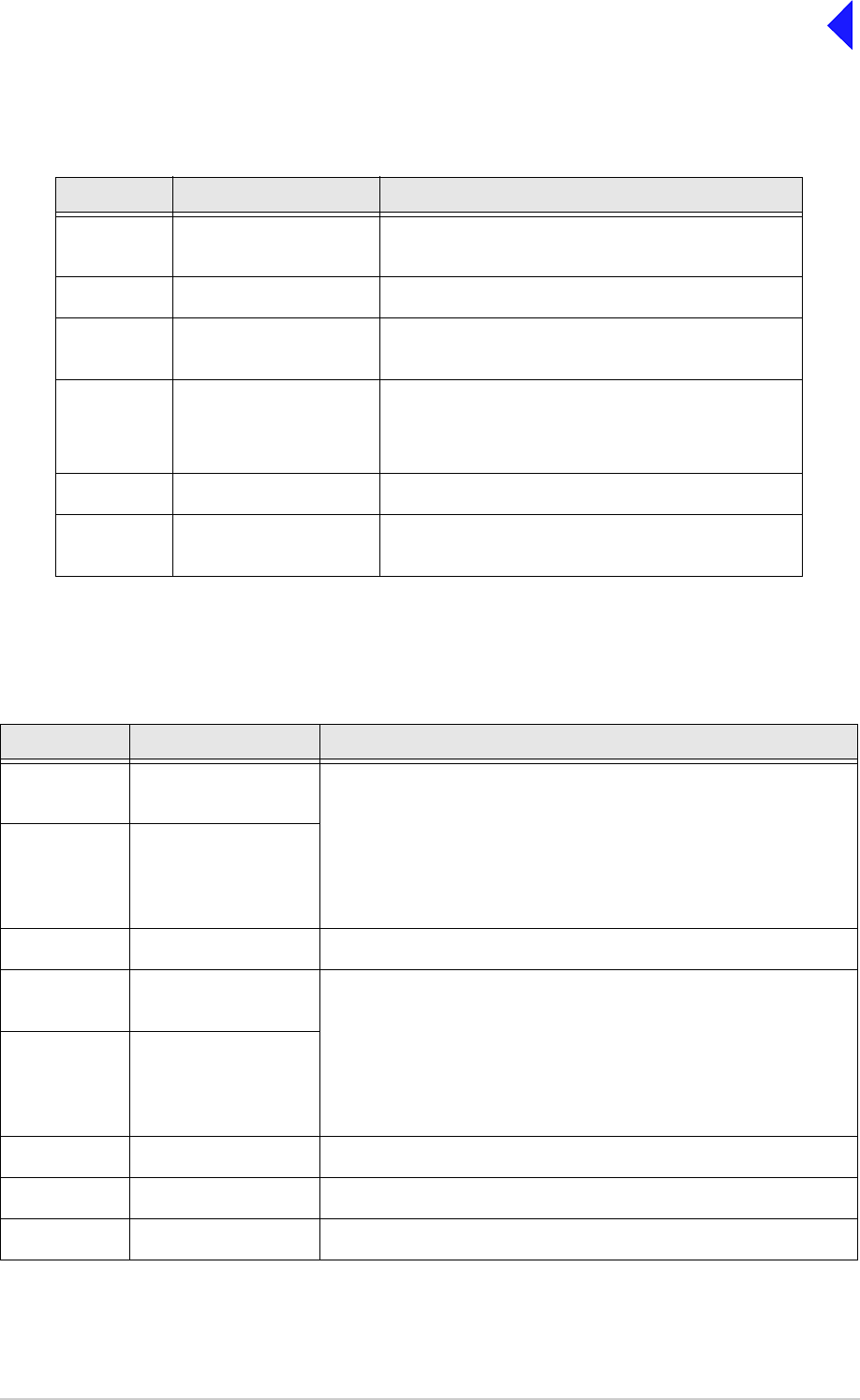
Page 19
Back to Transceiver
Main Page
MARC Data Connector
The MARC Data connector is an 8-way RJ48 socket. The connector pin-out is detailed in Table 7.
T1/E1 Connector
The T1/E1 connector is an 8-way RJ48 socket used for connecting to a Mode 3 network computer. The
connector pin-out is detailed in Table 8.
Table 7 MARC RJ48 Data Connector
Pin Number Signal Characteristic
1
2Data in -
Data in + RS422 differential asynchronous data, 9600 baud,
8 data bits, 1 stop bit, no parity, no handshaking.
3 Not connected -
4
5Data out +
Data out - RS422 differential asynchronous data, 9600 baud,
8 data bits, 1 stop bit, no parity, no handshaking.
6 Remote Supply ON/OFF
(input) 0 V to switch off.
Note: Rear panel switch must be in ON position for
this function to operate.
7 Ground 0 V.
8 Unregulated supply
(output) This output is between 21.6 and 32 Vdc (nominally
24 V) fused at 500 mA.
Table 8 T1/E1 Connector
Pin Signal Characteristic
1 RRing
(input) T1 - Balanced 100 ohm (±10%), 1.544 Mbits per second (±50 ppm),
AMI/B8ZS Coding.
E1 - Balanced 120 ohm (±10%), 2.048 Mbits per second (±50 ppm),
AMI/HDB3 Coding.
Protected with 28 V differential and common mode clamp and 1.25 A
fuse in each line.
2RTip
(input)
3 Not connected -
4TRing
(output} T1 - Balanced 100 ohm (±10%), 1.544 Mbits per second (±50 ppm),
AMI/B8ZS Coding.
E1 - Balanced 120 ohm (±10%), 2.048 Mbits per second (±50 ppm),
AMI/HDB3 Coding.
Protected with 28 V differential and common mode clamp and 1.25 A
fuse in each line.
5TTip
(output)
6 Not connected -
7 Not connected -
8 Not connected -

Page 20
Back to Transceiver
Main Page
HDLC Connector
The HDLC connector is an 8-way RJ48 socket used for connecting to a Mode 2 network computer. The
connector pin-out is detailed in Table 9.
External Speaker
The External Speaker connector is a 3.5 mm stereo jack used for connecting to an external speaker to
provide sidetone on the transceiver. This speaker should be a high impedance active type.
Table 9 HDLC Connector
Pin Signal Characteristic
1 HDLC RX A
(input) RS422 differential synchronous data, 128 kbytes per second
±50 ppm.2 HDLC RX B
(input)
3 HDLC CL A
(output) RS422 differential synchronous data, 128 kbytes per second
±50 ppm.
4 HDLC TX B
(output) RS422 differential synchronous data, 128 kbytes per second
±50 ppm.5 HDLC TX A
(output)
6 HDLC CL B
(output) RS422 differential synchronous data, 128 kbytes per second
±50 ppm.
7Ground 0 V.
8 Unregulated Supply
(output) 21.6 to 32 V, fused at 500 mA.
Table 10 External Speaker
Pin Signal Characteristic
Tip Speaker Drive (output) 0 to 3 V pk-pk. Connected directly to Ring.
Ring Speaker Drive (output) 0 to 3 V pk-pk. Connected directly to Tip.
Sleeve Ground 0 V.

Page 21
Back to Transceiver
Main Page
Facilities Connector
The Facilities connector is a 15-way D-type filtered socket used for connecting to associated parts of a
system. The connector pin-out is detailed in Table 11.
Table 11 Facilities Connector
Pin Number Signal Characteristic
1Ground 0V.
2 E-BIT (input) An external BIT input that connects from any ancillary equipment
having a compatible BIT alarm output.
When this input is active, the transceiver’s front panel Alarm indicator
flashes and an E-BIT message is displayed on the LCD. The input is
TTL having a 4.7 kohm pull-up resistor to 5 V. The input is
configurable from the front panel to be active high or low.
3 PTT (output) Grounding solid state relay. +60 to -60 V ac or dc, 100 mA max,
configurable n/o or n/c. Activated 35 ms (±1 ms) before the start of the
power ramp up to allow for the antenna relay pull in time.
4 External VSWR (input) TTL input with 4.7 kohm pull-up to 5 V. Configurable active high or
low.
5 Squelch (output) Solid state relay linked to pin 6. +60 to -60 V ac or dc, 100 mA max,
configurable n/o or n/c.
6 Squelch common
(output) Solid state relay linked to pin 5.
7 Squelch defeat (input) TTL with 4.7 kohm pull-up to 5 V. Configurable active high or low.
8Ground 0 V.
9 Unregulated supply
(output) 21.6 to 32 V, fused at 500 mA.
10 Inhibit (Input) TTL with 4.7 kohm pull-up to 5 V. Configurable active high or low.
11 BIT Interruptive test
(input) TTL with 4.7 kohm pull-up to 5 V. Configurable active high or low.
Must be asserted for >300 ms.
12 RSSI (output) 0 to 10 V.
13 Ready (output) Open collector NPN transistor grounding output, 200 mA max,
configurable n/o or n/c.
14 Tape (output) 0 dBm fixed output into 600 ohm for 90% modulation depth.
15 Reserved (output) Open collector NPN transistor grounding output, 200 mA max,
configurable n/o or n/c.
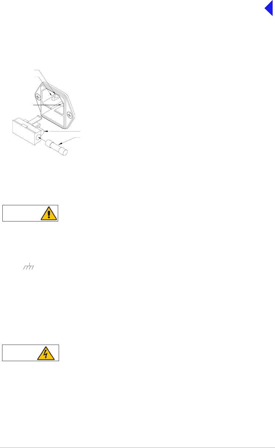
Page 22
Back to Transceiver
Main Page
Fitting the Correct AC Input Fuse
The mains input fuse F2 is an integral part of the rear panel ac connector (see Fig 11). The fuse type
must be correct for the local mains supply. Check the fuse fitted conforms to that detailed in Fig 15.
Fig 15
Fig 15 ac Input Fuse
Chassis Stud Connection
A chassis stud is fitted to the transceiver's rear panel. This stud is used to connect the
equipment to the equipment rack, or to the user's system earth point. The stud must not be
used as the safety earth.
In order not to compromise the transceiver’s Electromagnetic Compatibility (EMC) the chassis stud,
marked and fitted to the rear panel (see Fig 11) must be connected to the equipment rack (if a rack
is being used) or to the user's system earth point. The connection should be made using a single tri-rated,
green-and-yellow cable having a cross-sectional area of 2.5 mm2. The cable should have CSA and
UL1015 approval, and be connected to the chassis stud through an M6 eyelet (for example, Park Air part
number 20-08010103).
Failure to comply with this instruction could result in non-compliance with the European
Commission EMC Directive 89/336/EEC.
AC Supply Connection
The equipment is permanently connected to the mains supply when the mains connector is
attached. Switching the rear panel Power switch to off does not isolate all internal circuits
from the mains supply. For this reason, a mains isolating switch should be fitted close to,
and easily accessible from, the transceiver's position. The isolation switch should isolate
both live and neutral supplies, be clearly labelled, and adequately rated to protect the
equipment.
For a mains input in the range 110 to 120 Vac,
fuse F2 should be rated T4A, 125V, UL.
For a mains input in the range 110 to 240 Vac,
fuse F2 should be rated T4A, 250V, IEC.
FS2
Spare Fuse
Line
Neutral
Earth
WARNING Chassis Earth
WARNING Dangerous Voltages

Page 23
Back to Transceiver
Main Page
This equipment must be earthed. The earth terminal of the ac connector should be used as
the safety earth.
An ac input connector (see Fig 11 and Fig 15) is fitted to the equipment’s rear panel. The cable used to
connect between the equipment and the user’s ac power source should be 3-core (to IEC 227) rated
250 Vac at 8 amps, and have a minimum cross-sectional area of 1.0 mm2 per core. Park Air recommends
the use of polyvinyl chloride (PVC) insulated cable. The cable must be fitted with the IEC approved
equipment connector (Park Air part number 20-02030102) supplied with the transceiver, and conform to
the following specification:
❑If PVC insulated, be not lighter than ordinary polyvinyl chloride sheathed flexible cord according
to IEC publication 227 (designation H05 VV-F, or H05 VVH2-F).
❑If rubber insulated, be of synthetic rubber and not lighter than ordinary tough rubber-sheathed
flexible cord according to IEC publication 245 titled ‘Rubber Insulated Cables of Rated Voltages
up to and Including 450/750 V (designation H05 RR-F)’.
The T6TR transceiver is a Class 1 equipment. The ac supply cable should have a green-and-yellow
protective earthing conductor electrically connected to the protective earthing terminal of the equipment
connector and the mains plug. Park Air recommends the ac supply cable is colour coded in accordance
with the electrical appliance (colour code) regulations for the UK. That is:
❑The core coloured green-and-yellow must be connected to the terminal in the plug that is marked
with the letter E or by the earth symbol or coloured green-and-yellow.
❑The core coloured blue must be connected to the terminal that is marked with the letter N or
coloured black.
❑The core coloured brown must be connected to the terminal that is marked with the letter L or
coloured red.
DC Supply Connection
The transceiver operates from either an ac, or a dc input supply. When both ac and dc are connected,
operation from the ac supply takes priority; automatic change-over to the dc supply occurs if the ac
supply fails. On restoration of the ac supply, the equipment reverts to ac operation.
A dc input supply connector (see Fig 11) is fitted to the equipment's rear panel. The recommended
minimum rating of the dc supply cable is: 2-core having a cross-sectional area of 1.5 mm2 per core. The
supply cable should be fitted with an XLR3 connector (Park Air part number 20-01030106).
WARNING Earth Connection

Page 24
Back to Transceiver
Main Page
Switching On
When the POWER SWITCH is set to the Standby position, dangerous voltages are still present in
the transceiver's internal power supply circuitry. To ensure safe working, the transceiver must be
isolated from the ac and dc input supplies.
When installation is complete, the transceiver should be switched on at the rear panel 2-way rocker
Power switch. The Power switch is used to switch on, and switch off, power to the transceiver's circuitry
but does not remove power from the radio.
Under normal circumstances this screen is displayed when the radio is switched on.
The bottom row begins empty and dots are added as the initialisation progresses. When the initialisation
is complete the Main Screen is displayed.
Note ...
All radios have a standby function to extend power supply life when the radios are not required to be
operational. With the standby function enabled the transceiver is unable to transmit or receive and
the display is blank. Remote control serial ports and the front panel control knob remain active to
allow normal operation to be restored.
T 6 D i g i t a l R a d i o
( c ) 2 0 0 3 P a r k A i r
I n i t i a l i s i n g . . . .
...............
WARNING Dangerous Voltages
= Standby= On

Page 25
Back to Transceiver
Main Page
End of Document

Page 26
Back to Transceiver
Main Page


Page 2
Back to Transceiver
Main Page
General Information
This section provides the maintenance personnel with sufficient information to maintain and repair the
T6TR VHF transceiver. The standard maintenance policy regards the transceiver as a Line Replacement
Unit (LRU) which should be changed for a serviceable unit should a failure occur. Note that modules may
be changed on the advice of Park Air Customer Support (see following contact details).
Email address: Support@uk.parkairsystems.com.
Telephone during normal hours: From UK 01778 381557 or from outside UK 44 1778 381557.
Telephone out of normal hours: From UK 07733 124457 or from outside UK 44 7733 124457.
Caution ...
When replacing a Processor module ensure the correct module is fitted.
❑For radios at Mod Strike Level 5 the Processor Module part number is 68-60000671/F
(board issue 5).
❑For radios at Mod Strike Level 7 the Processor Module part number is 68-60000671/H
(board issue 7).
❑Note that Mod strike 6 was a special to type modification.
The following provides information that enables the user to:
❑Conduct scheduled maintenance tasks including checking/setting the reference frequency
oscillator to compensate for long term ageing effects
❑Identify any tools or test equipment required to maintain the transceiver
❑Use the built-in test facilities to check transceiver functionality
❑Remove a transceiver from service to dismantle and replace a faulty module, and where
applicable, realign the module
❑Install the Virtual Front Panel (VFP) software into a PC
❑Use the VFP to:
❑Download all radio settings to a file that can be stored/printed for reference
❑Change radio settings
❑Copy settings from one radio to another
❑Check a radio after repair and return it to service.
Refer to the Installation and Operating sections, available from the Main page of this document, for
complete installation and setting up procedures.
Included on the CD-ROM delivered with the radio is the VFP software. The software enables the original
settings to be re-loaded and alignment to be made if the transceiver's Processor, PA Control and
PA modules are ever replaced. The VFP software can be run from this document by clicking on ‘Back
to Transceiver Main Page’ (at top right of page) and from there, clicking on ‘Back to Main Page’ (at top
right of page). When the Main page is displayed select ‘Run the VFP Software’.
Note ...
A hard copy of the User Documentation is available. Contact Park Air for details.

Page 3
Back to Transceiver
Main Page
Transceiver Variants
Two variants of the T6TR VHF transceiver are available:
❑B6550/NB/50. This transceiver frequency operating range is 118.000 to 136.975 MHz. Power
output adjustable from 5 to 50 Watts. Frequency stability compliant with ICAO requirements for 2,
3 and 4-offset carrier applications
❑B6550/WB/50. This transceiver frequency operating range is 112.000 to 155.975 MHz. Power
output adjustable from 5 to 50 Watts. Frequency stability compliant with ICAO requirements for 2,
3 and 4-offset carrier applications.
Operating Frequency
The transceiver’s operating frequency can be changed by the user through the front panel, through the
VFP, through a T6 controller or through an associated MARC system (or compatible control data
system). Details of how to change the operating frequency from the front panel and VFP are contained
in this document. Details of how to change the frequency from MARC or a T6 controller can be found in
the MARC and T6 Controller User Guides respectively.
Input Supplies
The transceiver can be operated from standard ac input supplies, or from a low voltage dc supply. Both
ac and dc input supplies can be connected to the equipment. When both ac and dc supplies are
connected, operation from the ac supply takes priority; automatic change-over to the dc supply will occur
if the ac supply fails. On restoration of the ac supply, the equipment reverts to ac operation.
Built-in Test (BIT) Indications
The transceiver continuously self monitors key internal parameters without affecting normal operation. If
a BIT alarm is detected, the front panel Alarm indicator lights, the Ready indicator becomes unlit, and the
transceiver becomes inoperable. Additionally, a BIT alert, as opposed to a BIT alarm may be indicated.
A BIT alert is shown by the front panel Alarm indicator flashing; the Ready indicator remains lit and the
transceiver remains operational, but at reduced power. Conditions that cause a BIT alert are:
❑RF output has reduced from its setting by more than 3 dB
❑Supply volts has fallen below a pre-defined level.
In AM-voice and AM-MSK modes only, and in addition to continuous monitoring, an interruptive BIT test
can be initiated locally at the front panel or remotely. When initiated, test signals are injected that key the
transceiver allowing parameters to be monitored in their active state.
The results of continuous monitoring, and of interruptive testing, are available at the front panel LCD and,
if connected, the VFP PC. When the transceiver is used with a MARC system (or other compatible data
and control system) the results are also sent, in the form of a data message, to the monitoring facility.

Page 4
Back to Transceiver
Main Page
Configurations
The connectors used to configure the transceiver depend on the required operating mode. The purpose
of each connector is detailed in the following text. Configuration details can be found in the Installation
section of this document.
Antenna Connector Used in all operating modes to connect the 50 ohm antenna
feeder cable.
Headset/Microphone/Diagnostics This is a dual purpose connector. A microphone/headset
Connector(complete with integral PTT switch) can be connected
to enable
local AM-voice operation. Alternatively, a PC can be connected to
allow use of the VFP. The VFP can be used to set the
transceiver's operational settings, or to download new software.
Reference Connector Used in all operating modes to check and reset the transceiver's
reference frequency.
Facilities Connector Used primarily to connect remote signals when using AM-voice
mode and the transceiver does not form part of a MARC system.
Some auxiliary signals available at this connector, for example
the 24 volt (nominal) unregulated output supply, can be utilized
irrespective of the operating mode.
MARC Port The MARC port is used to connect received audio, squelch
indication and data to a MARC system via an RSE2.
MARC Audio The MARC Audio port is used for connecting transmit audio and
PTT to a MARC system via an RSE2.
MARC Data The MARC Data port is used for connecting data to a MARC
system.
T1/E1 The T1/E1 port is an 8-way RJ48 socket used for connecting a
Mode 3 network computer.
HLDC The HLDC port is an 8-way RJ48 socket used for connecting a
Mode 2 network computer.
Page 5
Back to Transceiver
Main Page
Maintenance Procedures
The instructions given in this section involve connecting dangerous voltages to the
transceiver. The instructions detailed in this document must be carried out only by suitably
qualified personnel.
When an ac supply is connected, lethal voltages are present within the transceiver. Care
must be taken by personnel to avoid accidental contact with exposed circuitry during
maintenance or alignment procedures.
When the power switch is set to the off position, lethal voltages are still present in the
transceiver's internal power supply circuitry. To ensure safe working, the ac and dc input
supplies must be disconnected from the transceiver.
The antenna used with the transceiver must be installed such that the resultant radiated field
strength is below 10 W/m² in areas normally accessible to personnel.
The T6TR transceiver’s circuitry contains Electrostatic Sensitive Devices (ESSDs).
Personnel must be aware of the precautions necessary to prevent damage to such devices.
Changes or modifications made to this equipment that are not expressly approved by
Park Air, or parties authorized by Park Air, could void the user’s authority to operate the
equipment.
(1) When carrying out repairs to the PA module, care must be taken not to damage the gasket.
If the strips become damaged, they must be replaced. Failure to comply with this
instruction may compromise the transceiver’s Electromagnetic Compatibility (EMC) and
breach European Commission regulations.
(2) When screws are inserted into the transceiver PA casting care must be taken not to
exceed a torque of 6 Ibs/inch when tightening. This applies when replacing the top and
bottom covers and during the refitting of the PA module.
WARNING Dangerous Voltages
WARNING Antenna Radiation
Caution ESSDs
Caution Unauthorized Modifications
Caution Repairs

Page 6
Back to Transceiver
Main Page
Introduction
This part of the Maintenance section covers maintenance tasks that include schedule maintenance,
dismantling and assembly instructions and fault finding. Due to the complexity of most modules the
recommended policy is repair by replacement of the radio. However module replacement information is
supplied in the event that Park Air Customer Support advises this may be done.
A faulty module may be traced by aid of the front panel LCD and Scroll/Select control; VFP or MARC.
Note ...
Access to a PC is essential when fitting spares.
During all maintenance tasks the warnings and cautions given in this section should strictly be adhered to.
For maintenance purposes and loading new software, a Virtual Front Panel (VFP) is used. The VFP is a
standard PC loaded with a bespoke software package for carrying out these tasks. Separate VFP
operational instructions are included in Part 3 of this section of the document.
Tools, Materials and Test Equipment Required
The following tools, materials and test equipment should be made available to complete the maintenance
tasks described in this section:
Scheduled Maintenance
Park Air recommends that this is carried out at twelve-monthly intervals. Schedule maintenance
comprises:
(1) Ensuring the equipment is clean (see page 7).
(2) Ensuring that the external connectors are securely fitted to the transceiver (see page 7).
(3) Checking and resetting (if required) the transceiver's frequency standard (see page 7).
(4) Performing a BIT interruptive test (see page 7).
(5) Performing an ac and dc change-over check (see page 9).
❑Personal Computer (PC)
❑General Purpose Toolkit (including a
1.5 mm Allen key)
❑6BA Nut Spinner
❑Camel Hair Brush
❑Clean Lint-free Cloths
❑Frequency Counter
❑Power Meter
❑Dummy Load
❑PC to Radio Interconnection Lead
(Park Air part number 17E12600001)

Page 7
Back to Transceiver
Main Page
Schedule Maintenance Procedure
The procedure, detailed in the following paragraphs, should be followed when carrying out schedule
maintenance.
Cleaning the Equipment
Remove all dust and dirt from the equipment's exterior using the cleaning cloths and camel hair brush.
Clean the front panel indicators and LCD face.
Security of External Connections
Check all external connections are secure and free from damage.
Setting the Transceiver’s Internal Reference Frequency
To set the transceiver’s internal reference frequency, use the following procedure. Note that references
to the switch in the procedure mean the Scroll/Select switch.
(8) Disconnect the frequency counter.
(9) Refer to AM-Voice Mode Settings Screen in the Operation section of this document and set to
the required offset.
To Initiate a BIT Test
Use the following procedure to initiate an interruptive BIT test from the transceiver's front panel. A BIT
test cannot be initiated while the transceiver is keyed. An interruptive BIT test cannot be initiated in
Mode 2 or Mode 3.
AM-Voice Mode Settings Screen
Control Screen
Settings Screen
A N T C / O D e l
O f f s e t 0 . 0 k H z
S q u e l c h - 1 0 7 d B m
E x i t < < > >
F r e q u e n c y
C h a n n e l
S e t t i n g s
E x i t
B a n d E d g e s
R e f F r e q 5 0 . 0 %
B a c k l i g h t 0 3 0 s
E x i t < < > >
(1) Refer to AM-Voice Mode Settings
Screen in the Operation section of this
document and set the offset to 0 kHz.
(2) Select Exit and return to the Main
screen.
(3) Connect a high impedance frequency
counter to the front panel Reference
connector.
(4) From the Main screen, press the switch
to display the Control screen. Turn the
switch until Settings is highlighted.
Press the switch.
(5) Ensure the Settings screen is displayed.
Turn the switch until Ref Freq is
highlighted, then press the switch.
(6) With Ref Freq selected turn the switch
clockwise or anti-clockwise until the
frequency counter reads 20.950000 MHz
±10 Hz, then press the switch.
(7) Turn the switch clockwise until Exit is
highlighted, then press the switch. You
are returned to the Main screen.

Page 8
Back to Transceiver
Main Page
(1) From the Main screen, press the switch to
display the Control screen. Turn the switch
until BIT is highlighted. Press the switch.
(2) Ensure the BIT menu is displayed. Turn the
switch until BIT Initiate is highlighted. Press
the switch.
(3) During the test, which takes approximately
two seconds, the Testing screen is
displayed.
On completion, and if the interruptive test was initiated from the front panel, one of the following screens
will be shown.
(4) Selecting OK takes the user back to the BIT
screen.
.
(5) Selecting OK takes the user back to the BIT
screen. The user can then scroll through the
screen to check out transceiver parameters
for failure.
During an interruptive BIT test, the transceiver radiates modulated carrier waves at the set
power. Users should therefore obtain the necessary authority before initiating a test.
If the test is to be carried out with the antenna disconnected, ensure a load is fitted to the
transceiver's Antenna (not Rx Antenna) connector.
In order to test the line input stages, an internally generated 1 kHz tone is injected into the
line input circuit. Any other audio present on the line input will cause the test to be
inaccurate. Therefore the transceiver must not be keyed during the test.
B I T
S / W C o n f i g
S t a n d b y
E x i t < <
B I T I n i t i a t e
E T I 0 0 0 0 0 : 0 0 h r s
A C S u p p l y O N
E x i t > >
T e s t i n g
P l e a s e W a i t
T e s t S t a t u s
P A S S
O K
T e s t S t a t u s
F A I L
O K

Page 9
Back to Transceiver
Main Page
AC and DC Change-over Check
If both ac and dc input supplies are connected to the transceiver, carry out the following check:
(1) Confirm that both ac and dc supplies are connected to the transceiver. Ensure that the rear panel
Power switch is set to the I (on) position.
(2) Confirm that the front panel Ready indicator is lit, the LCD is illuminated, and the transceiver is
operational.
(3) Switch off the ac supply from its source.
(4) Check that the transceiver continues to operate correctly from the dc supply. If accessed, the
front panel BIT screen will show AC Supply as off and DC supply as on. The value of the dc
supply is also shown.

Page 10
Back to Transceiver
Main Page
Dismantling and Assembly Instructions
Introduction
This topic provides the user with detailed instructions on the removal and replacement of modules and
assemblies. Access to a PC loaded with VFP software, and a radio to PC serial interconnection lead,
Park Air part number 17E12600001 is essential when carrying out these instructions.
The transceiver’s modules and assemblies are accessed by removing the top and bottom covers. The
top cover is secured by 18 countersunk screws and the bottom cover by 15 countersunk screws. To
remove a module from the transceiver, follow the instructions detailed in the following paragraphs (see
Fig 3 for module locations when covers are removed).
Cautions ...
(1) When removing or refitting modules, observe antistatic handling precautions.
(2) Do not change any potentiometer (or link) settings unless detailed in these instructions.
Potentiometers have been set using specialist equipment.
(3) The transceiver uses the following Molex KK connectors:
CN2 on the PA Control/Rx RF module
CN7 and CN6 on the PSU Regulator module
CN3 on the Front Panel PCB.
To remove KK type connectors:
❑Free the locking mechanism on the connector by moving one side of the connector up, then
move the other side up (see the following diagram). The upward motion should only be as far
as needed to free the locking mechanism.
❑DO NOT pull the cable to free the connector.
❑Note that KK type connectors are designed to be removed in this manner to free the locking
mechanism. Do not use this procedure with non-KK type connectors as damage to the
connector may occur.
Top Cover
To remove the top cover, locate and unscrew the 18 countersunk screws securing the top cover to the
mainframe. Access can then be gained to the following modules:
❑Processor module
❑PSU Regulation module
❑Power Supply (requires both top and bottom covers to be removed)
❑Front Panel assembly (requires both top and bottom covers to be removed).
Dangerous voltages are present within the transceiver. Care must be taken by personnel to
avoid accidental contact with exposed circuitry when the top cover is removed and power is
applied to the radio.
Lift 2Lift 1
PCB
WARNING Dangerous Voltages

Page 11
Back to Transceiver
Main Page
Removing and Refitting the Processor Module
The Processor module is located as shown in Fig 3. A module removal diagram is shown in Fig 4.
Removal
Before attempting to remove the Processor module, and if possible, save the equipment settings. To
achieve this connect a PC, with the VFP software loaded, to the radio using the PC to Radio
Interconnection Lead (Park Air part number 17E12600001). With the VFP software active, upload the
radio settings to a specified file.
Ensure that the transceiver is isolated from the ac and dc input supplies. Then proceed as follows:
(1) Remove the transceiver’s top cover as described on page 10 (take heed of the warning).
(2) Locate the Processor module and disconnect the following connectors:
❑CN1 50-way connector (50-way ribbon cable from PA Control/Rx RF module)
❑CN3 14-way connector (14-way ribbon cable from PSU Regulator module)
❑CN4 34-way connector (34-way ribbon cable from Front Panel module)
❑CN2 SMB connector (to PA Control/Rx RF module).
(3) Gain access to the rear of the transceiver. Using a 6BA nut spinner tool, remove the four
screwloc 8 mm-4-40 UNC screws that secure the Processor module interface connectors CN5
and CN6 to the rear panel.
(4) Remove the 11 (Mod Strike 5 modules), 7 (Mod Strike 6 and 7 modules) M3 x 8 mm screws that
secure the module to the transceiver’s mainframe.
(5) Remove the module from the chassis.
Refitting
To refit the Processor module, proceed as follows:
(1) Place the module in position. Ensure no wires are trapped by the module. Ensure jumper J2 on
the module is set to ‘R/TR’ for transceiver (see diagram on this page).
(1) Ensure the module’s interface connectors CN5 and CN6 are located correctly and are aligned
with the screw holes in the rear panel. Fit the four screwloc 8 mm-4-40 UNC screws and wavy
washers but leave them loose.
IC25
T2 C84
TS7
IC27
JP2
Shown set for
Transceiver
T
T
R/TR
R/TR
IC21
IC20IC19
IC38
T3

Page 12
Back to Transceiver
Main Page
(2) Fit the 11 (Mod Strike 5 modules), 7 (Mod Strike 6 and 7 modules) M3 x 8 mm screws that secure
the module to the transceiver’s mainframe, but leave them loose.
(3) Using a nut spinner tool, tighten the four screwloc 8 mm-4-40 UNC screws and wavy washers
that secure the connectors; then tighten the 11 (Mod Strike 5 modules), 7 (Mod Strike 6 and 7
modules) M3 x 8 mm screws that secure the module to the receiver’s mainframe.
(4) Refit the following connectors to the module:
❑CN1 50-way connector (50-way ribbon cable from PA Control/Rx RF module)
❑CN3 14-way connector (14-way ribbon cable from PSU Regulator module)
❑CN4 34-way connector (34-way ribbon cable from Front Panel module).
(5) Re-establish the ac and/or dc supplies (take heed of the warning on page 10).
(6) Switch power on at the radio using the rear mounted Power switch.
(7) Ensure the front panel Ready indicator is lit and the Alarm Indicator is unlit.
(8) If a new module has been fitted, connect the VFP PC to the radio using the PC to Radio
Interconnection Lead, Park Air part number 17E12600001 (if not already connected). Note that
any module sent from Park Air as a spare for a particular radio will be programmed with
compatible operating and Fill software. Park Air keeps records of module software in all radios
supplied. Care must be taken when using a module removed from another radio as this module
may not have compatible software.
(9) If saved during the removal procedure, download the radio settings from file using the VFP (see
VFP information starting on page 21). Alternatively the settings can be edited by hand as
described in the Operation section of this document. Once entered, ensure the required settings
appear in the VFP screen.
(10) Carry out the Calibrate routine using the Virtual Front Panel (VFP), as detailed in the procedure
To Calibrate the Transceiver on page 26.
(11) Carry out a BIT interruptive test as detailed in the procedure To Initiate a BIT Test on page 7.
(12) Remove the VFP PC to radio interconnection lead and switch power off at the transceiver using
the rear mounted Power switch. Isolate the transceiver from the ac and/or dc supplies.
(13) Refit the transceiver’s top cover (take note of repairs caution (1) on page 5 before carrying out
this task). The transceiver can now be returned to service.

Page 13
Back to Transceiver
Main Page
Removing and Refitting the PSU Regulator Module
The PSU Regulator module is located as shown in Fig 3. A module removal diagram is shown in Fig 5.
Removal
Before attempting to remove the PSU Regulator module, ensure that the transceiver is isolated from the
ac and dc input supplies. Then proceed as follows:
(1) Remove the transceiver’s top cover as described on page 10 (take heed of the warning).
(2) Locate the PSU Regulator module and remove the three M3 x 8 mm captive washer screws that
secure the module to the transceiver’s mainframe.
(3) Carefully raise the module to gain access to the module connectors.
(4) Disconnect the following connectors:
❑CN5 10-way connector (10-way ribbon cable to PA Control/Rx RF module)
❑CN6 6-way connector (2-way loom to power supply). Note caution (3) on page 10
❑CN4 14-way connector (14-way ribbon cable to Processor module)
❑CN3 3-way connector (3-wire loom to PA module)
❑CN7 3-way connector (3-wire loom to rear panel On/Off switch). Note caution (3) on page 10
❑CN2 2-way connector (2-wire loom from dc input connector on rear panel)
❑CN1 4-way connector (4-wire cable from power supply)
❑CN9 2-way connector (2-wire cable ac input to power supply)
❑CN8 3-way connector (2-wire loom to rear panel ac input connector plus chassis connection).
(5) Remove the module from the chassis.
Refitting
To refit the PSU Regulator module, proceed as follows:
(1) While holding the module in position, connect the following connectors:
❑CN8 3-way connector (2-wire loom to rear panel ac input connector plus chassis connection)
❑CN9 2-way connector (2-wire cable ac input to power supply)
❑CN1 4-way connector (4-wire cable from power supply)
❑CN2 2-way connector (2-wire loom from dc input connector on rear panel)
❑CN7 3-way connector (3-wire loom to rear panel On/Off switch)
❑CN3 3-way connector (3-wire loom to PA module)
❑CN4 14-way connector (14-way ribbon cable to Processor module)
❑CN6 6-way connector (2-way loom to power supply)
❑CN5 10-way connector (10-way ribbon cable to PA Control/Rx RF module).
(2) Locate the module in position. Ensure no wires are trapped by the module.
(3) Secure the module to the transceiver’s mainframe using the three M3 x 8 mm captive washer
screws removed during the removal procedure.
(4) Re-establish the ac and/or dc supplies (take heed of the warning on page 10).
(5) Switch power on at the radio using the rear mounted Power switch.
(6) Ensure the front panel Ready indicator is lit and the Alarm indicator is unlit.
(7) Carry out a BIT interruptive test as detailed in the procedure To Initiate a BIT Test on page 7.

Page 14
Back to Transceiver
Main Page
(8) Switch power off at the transceiver using the rear mounted Power switch. Isolate the transceiver
from the ac and/or dc supplies.
(9) Refit the transceiver’s top cover (take note of repairs caution (1) on page 5 before carrying out
this task). The transceiver can now be returned to service.
Bottom Cover
To remove the bottom cover, locate and unscrew the 15 captive screws securing the bottom cover to the
mainframe. Access can then be gained to the following modules:
❑PA Control/Rx RF module
❑Power supply (requires top and bottom covers to be removed)
❑PA module (requires top cover and bottom covers to be removed)
❑Front Panel assembly (requires top cover and bottom covers to be removed).
Dangerous voltages are present within the transceiver. Care must be taken by personnel to
avoid accidental contact with exposed circuitry when the bottom cover is removed and
power is applied to the radio.
Removing and Refitting the PA Control/Rx RF Module
The PA Control/Rx RF module is located as shown in Fig 3. A module removal diagram is shown in Fig 6.
Removal
Before attempting to remove the PA Control/Rx RF module, ensure that the transceiver is isolated from
the ac and dc input supplies.
Then proceed as follows:
(1) Remove the transceiver’s bottom cover as described above (take heed of the warning).
(2) Locate the module and disconnect the following connectors (before removing CN7 and CN12,
note the antenna configuration):
❑CN1 50-way connector (50-way ribbon cable from Processor module)
❑CN6 10-way connector (10-way ribbon cable from PSU Regulator module)
❑CN5 SMB connector (reference frequency)
❑CN3 SMB connector (RF drive)
❑CN4 SMB connector (forward power sense)
❑CN2 6-way connector (to PA module). Note caution (3) on page 10)
❑CN8 SMB connector (to Processor Module)
❑CN7 SMB connector from the Rx antenna connection or CN13 on the PA module (see
antenna configuration on page 16)
❑CN12 SMB connector (connects to CN13 on the PA module) or Rx antenna connection (see
configuration on page 16).
(3) Remove the seven M3 x 8 mm captive washer screws that secure the module to the transceiver’s
mainframe.
(4) Remove the module from the chassis.
WARNING Dangerous Voltages

Page 15
Back to Transceiver
Main Page
Refitting
To refit the PA Control/Rx RF module, proceed as follows:
(1) Place the module in position. Ensure no wires are trapped by the module.
(2) Fit the seven M3 x 8 captive washer screws that secure the module to the transceiver’s
mainframe.
(3) Refit the following connectors to the module:
❑CN7 SMB connector to the Rx antenna connection or to the connector from CN13 on the
PA module (see antenna configuration on page 16)
❑CN12 SMB connector to the CN13 on the PA module or Rx antenna connection (see
configuration on page 16)
❑CN8 SMB connector (to Processor Module)
❑CN2 6-way connector (to PA module)
❑CN4 SMB connector (forward power sense)
❑CN3 SMB connector (RF drive)
❑CN5 SMB connector (reference frequency)
❑CN6 10-way connector (10-way ribbon cable from PSU Regulator module)
❑CN1 50-way connector (50-way ribbon cable from Processor module).
(4) Re-establish the ac and/or dc supplies (take heed of the warning on page 14).
(5) Switch power on at the radio using the rear mounted Power switch.
(6) Ensure the front panel Ready indicator is lit and the Alarm indicator is unlit.
(7) Carry out the Calibrate routine using the Virtual Front Panel (VFP), as detailed in the procedure
To Calibrate the Transceiver on page 26
(8) Carry out a BIT interruptive test as detailed in the procedure To Initiate a BIT Test on page 7.
(9) Remove the VFP PC to radio interconnection lead and switch power off at the transceiver using
the rear mounted Power switch. Isolate the transceiver from the ac and/or dc supplies.
(10) Refit the transceiver’s bottom cover. The transceiver can now be returned to service.
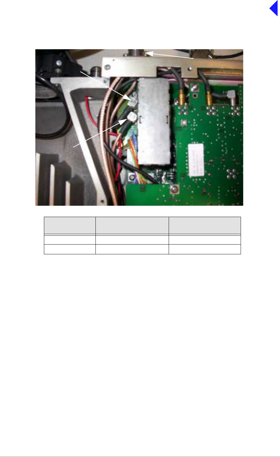
Page 16
Back to Transceiver
Main Page
Antenna
Configuration Connector CN12
PARK Connector CN7
Single Rx antenna CN13 (from PA Module)
Dual CN13 (from PA Module) Rx antenna
CN7
CN12
PARK
RX Antenna
Connector
Antenna Configuration
Antenna Configuration

Page 17
Back to Transceiver
Main Page
Removing and Refitting the Power Supply
The Power Supply is located as shown in Fig 3. A module removal diagram is shown in Fig 7.
Removal
Before attempting to remove the Power Supply, ensure that the transceiver is isolated from the ac and
dc input supplies. Then proceed as follows:
(1) Remove the transceiver’s top and bottom covers as described on page 10 and page 14 (take
heed of the warnings on those pages).
(2) Support the radio on its side.
(3) Locate the power supply. From the bottom half of the unit remove the four No. 6 x 32 UNC
countersunk screws that secure the power supply to the transceiver’s mainframe. During this
operation support the power supply from the top half of the unit.
(4) Withdraw the power supply from the chassis sufficient to allow access to the power terminal
blocks taking care not to damage the ac terminal plastic supply guard.
(5) Remove the connector CN4 (power supply to the power regulator).
(6) Disconnect the dc wires from the eight connector terminal block.
(7) Slide back the terminal block cover and disconnect the ac wires from the three connector terminal
block (marked L N E).
(8) Carefully remove the power supply from the transceiver.
Refitting
(1) With the transceiver on its side hold the power supply near to its securing position in the top half
of the radio.
(2) Slide back the terminal block cover and connect the ac wires to the three connector terminal
block (marked L N E); brown to terminal L, blue to terminal N and yellow/green to terminal E.
(3) Connect the dc wires to the eight connector terminal block; red to terminal 2 and terminal 3 and
black to terminal 6 and terminal 7.
(4) Connect connector CN4.
(5) Taking care not to damage the plastic supply guard, lower the Power Supply into position and
secure from the bottom half of the unit using the four countersunk screws.
(6) Re-establish the ac and/or dc dc supplies (take heed of the warnings on page 10 and page 14).
(7) Switch power on at the radio using the rear mounted Power switch.
(8) Ensure the front panel Ready indicator is lit and the Alarm indicator is unlit.
(9) Carry out a BIT interruptive test as detailed in the procedure To Initiate a BIT Test on page 7.
(10) Switch power off at the transceiver using the rear mounted Power switch. Isolate the transceiver
from the ac and/or dc supplies.
(11) Refit the transceiver’s top and bottom covers (take note of Repairs caution (1) on page 5 before
carrying out this task). The transceiver can now be returned to service.

Page 18
Back to Transceiver
Main Page
Removing and Refitting the PA Module
The PA module is located as shown in Fig 3. A module removal diagram is shown in Fig 8.
Removal
Before attempting to remove the PA module, ensure that the transceiver is isolated from the ac and dc
input supplies. Then proceed as follows:
(1) Remove the transceiver’s top and bottom covers as described on page 10 and page 14 (take
heed of the warnings on those pages).
(2) Remove CN3 from the PSU Regulator module.
(3) With the transceiver upside-down disconnect CN2 from the PA Control/Rx RF module.
(4) Disconnect the SMB connectors CN8 and CN10. Note that CN10 is located within the heatsink
fins and should be disconnected using long nosed pliers. Do not attempt to remove the connector
by pulling on the cable.
(5) Remove the black equipment handle from the PA side of the radio by unscrewing and removing
the two M5 x 16 mm panhead screws that secures it to the transceiver.
(6) Remove the six M3 x 8 mm countersunk screws and two M3 x 8 mm captive screws that secure
the PA from the bottom and top of the mainframe as shown in Fig 8. Ensure the PA module is
well supported during this operation.
(7) Withdraw the PA module from the mainframe taking care not to snag the wiring looms.
Refitting
Note ...
Take note of Repairs caution (2) on page 5 before fitting the PA module.
To refit the PA module, proceed as follows:
(1) Place the module in position and butt it up to the mainframe. Ensure no wires are trapped by the
module.
(2) Fit the six M3 x 8 countersunk screws and two M3 x 8 mm captive screws that secure the module
to the transceiver’s mainframe.
(3) Fit the black equipment handle to the PA side of the radio using the two M5 x 16 mm panhead
screws.
(4) Connect the SMB connectors CN8 and CN10. Note that CN10 is located within the heatsink fins
and should be connected using long nosed pliers if unable to use fingers in the enclosed space.
(5) With the transceiver upside-down connect CN2 to the PA Control/Rx RF module.
(6) Fit CN3 to the PSU Regulator module.
(7) Re-establish the ac and/or dc supplies (take heed of the warnings on page 10 and page 14).
(8) Switch power on at the radio using the rear mounted Power switch.
(9) Ensure the front panel Ready indicator is lit and the Alarm indicator is unlit.
(10) Carry out the Calibrate routine using the Virtual Front Panel (VFP), as detailed in the procedure
To Calibrate the Transceiver on page 26.
(11) Carry out a BIT interruptive test as detailed in the procedure ‘To Initiate a BIT Test on page 7’.
(12) Remove the VFP PC to radio interconnection lead and switch power off at the transceiver using
the rear mounted Power switch. Isolate the transceiver from the ac and/or dc supplies.
(13) Refit the transceiver’s top and bottom covers (take note of Repairs caution (1) on page 5 before
carrying out this task). The transceiver can now be returned to service.

Page 19
Back to Transceiver
Main Page
Removing and Refitting the Front Panel Assembly PCB
The Front Panel assembly PCB is located as shown in Fig 3. An assembly and PCB removal diagram is
shown in Fig 9.
Removal
Before attempting to remove the Front Panel assembly PCB, ensure that the transceiver is isolated from
the ac and dc input supplies. Then proceed as follows:
(1) Remove the transceiver’s top and bottom covers as described on page 10 and page 14 (take
heed of the warnings on those pages).
(2) Disconnect CN4 at the Processor module. Carefully pull the cable through the aperture in the
mainframe to free it.
(3) Disconnect SMB connector CN5 at the PA Control/RxRF module.
(4) Remove the four M3 x 8 mm countersunk screws from the bottom and top of the mainframe box
section (see Fig 9, Diagram A).
(5) Remove the two black equipment handles by unscrewing and removing the four M5 x 16 mm
panhead screws that secure them to the transceiver. The front panel can now be moved forward
and away from the mainframe.
(6) At the front panel, release the control knob by unscrewing the Allen head grub screw using a
1.5 mm Allen key. Withdraw the control knob from the spindle.
(7) Disconnect the speaker connector from the Front Panel PCB.
(8) Remove the Front Panel PCB from the Front Panel assembly by removing the six M3 x 6 mm
panhead screws and wavy washers (see Fig 9 Diagram B).
Refitting
To refit the Front Panel assembly PCB, proceed as follows:
(1) Place the PCB in position at the Front Panel assembly. Ensure the spindle of the control knob
and Heaset/Microphone/Diagnostics connector are correctly located.
(2) Secure the PCB to the Front Panel assembly using the six M3 x 6 mm panhead screws and wavy
washers (see Fig 9, Diagram B).
(3) Connect the speaker connector to the Front Panel PCB.
(4) At the front panel, place the control knob onto the spindle and using a 1.5 mm Allen key, secure
the Allen head grub screw.
(5) Secure the Front Panel assembly to the top and bottom of the mainframe box section using the
four M3 x 8 mm countersunk screws. Fit the two black equipment handles using the four
M5 x 16 mm panhead screws (see Fig 9, Diagram A).
(6) Route the ribbon cable to the Processor module connector CN4 and connect it.
(7) Route the SMB connector to CN5 on the PA Control/RxRF module and connect it.
(8) Re-establish the ac and/or dc supplies (take heed of the warnings on page 10 and page 14).
(9) Switch power on at the radio using the rear mounted Power switch.
(10) Ensure the front panel Ready indicator is lit and the Alarm indicator is unlit.
(11) Carry out a BIT interruptive test as detailed in the procedure To Initiate a BIT Test on page 7.
(12) Switch power off at the transceiver using the rear mounted Power switch. Isolate the transceiver
from the ac and/or dc supplies
(13) Refit the transceiver’s top and bottom covers (take note of repairs caution (1) on page 5 before
carrying out this task). The transceiver can now be returned to service.

Page 20
Back to Transceiver
Main Page
Removing and Refitting the Cooling Fan
The cooling fan is at the rear of the PA module as shown in Fig 3. An assembly and removal diagram is
shown in Fig 10.
Removal
Before attempting to remove the fan, ensure that the transceiver is isolated from the ac and dc input
supplies. Then proceed as follows:
(1) Disconnect the two-pin connector.
(2) Remove fan's finger guard.
(3) Using an Allen key, inserted through the holes in the fan exposed with the finger guard removed,
remove the three M4 x 12 mm caphead Allen screws that secure the fan to the PA module
heatsink.
(4) Remove the fan from the PA module.
Refitting
To refit the cooling fan, proceed as follows:
(1) Locate the fan in position and using a suitable Allen key inserted through the holes for the fan's
finger guard, secure using the four M4 x 12 mm caphead Allen screws.
(2) Secure the finger guard to the fan.
(3) Connect the 2-pin fan connector to the fan. Ensure the + marked socket mates with the + marked
plug on the fan.
(4) Re-establish the ac and/or dc supplies.
(5) Switch power on at the radio using the rear mounted Power switch.
(6) Ensure the front panel Ready indicator is lit and the Alarm indicator is unlit.
(7) Carry out a BIT interruptive test as detailed in the procedure ‘To Initiate a BIT Test on page 7’.
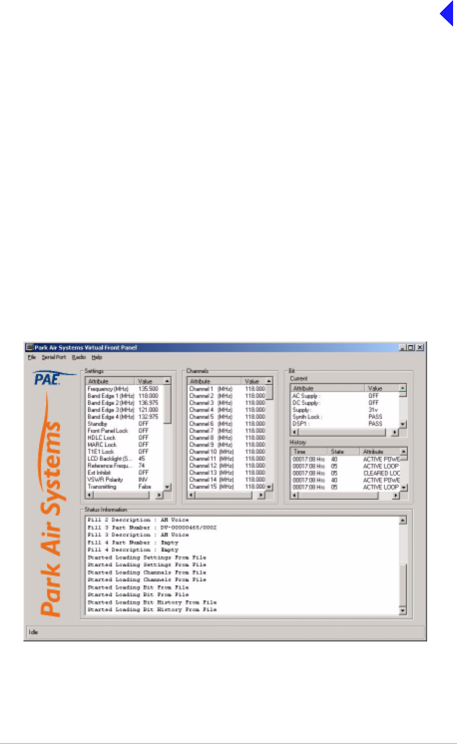
Page 21
Back to Transceiver
Main Page
Virtual Front Panel (VFP)
Virtual Front Panel (VFP) software is supplied on CD-ROM and is compatible with any PC or laptop
running Windows 2000™ or Windows XP™. The VFP allows changes to a radio’s settings and channel
information, it displays the current BIT state, displays BIT history, allows security locks to be set, and
provides maintenance facilities.
A radio can be set up using the front panel Scroll/Select switch and LCD, or by using the VFP. Using the
VFP has several advantages over setting the transceiver from the front panel; these are:
❑A profile of the transceiver’s operation settings and channel information can be created, stored on
disk, and then recalled to download into other transceivers.
❑A print out of the transceiver’s profile can be made from the VFP.
❑Front Panel Lock is available only when using the VFP. As part of the transceiver’s Settings (see
typical screen display shown below) Front Panel Lock can be set to ON. When selected to on, no
settings or frequency information can be changed from the front panel.
❑If the transceiver is part of a MARC system or operates in a digital mode, a MARC Lock, HDLC
Lock and T1E1 Lock are available when using the VFP. When selected to on, no settings or
frequency information can be changed from the MARC equipment screen, or the digital control
equipment.
Typical VFP Screen - AM-Voice Profile Shown

Page 22
Back to Transceiver
Main Page
Installing the VFP Software
The VFP software is supplied by Park Air on CD-ROM. The software can be run from the Main page or
installed on your PC via Explorer.
To install the software onto your PC:
(1) Using explorer, display the contents of the CD-ROM supplied by Park Air. Identify the file named
S0473VXX.EXE.
(2) Using the mouse, right click on the file S0473VXX.EXE and then select Copy.
(3) Display the Windows desktop. Right click anywhere on the desktop and select Paste.
(4) Check that the VFP icon is shown on the desktop. Reposition the icon as required. The VFP
application is now installed on the PC’s desktop.
VFP Icon
VFP Features
The VFP screen is divided into four main windows: Settings, Channels, BIT and Status Information. Four
colours are used to display text. The colours have the following meanings:
❑Black indicates a valid parameter that has been accepted by the radio.
❑Red indicates an invalid parameter that has been rejected by the radio, or a BIT failure.
❑Green indicates text that has not yet been downloaded to the radio. Text loaded into the VFP from
a previously stored file, or any text that is manually amended is green until it is downloaded into
the radio; after being downloaded into the radio the text changes to black, or if it is invalid, to red.
❑Blue indicates Help text and is shown in the Status Information window.
The Menu Bar
The menu bar has four categories: File, Serial Port, Radio and Help.
File Has the sub-categories: Open, Save and Print. These sub-categories allow the user to
open previously saved profiles, save a new profile, or print a profile.
A special sub-category: File > Save > Diagnostics should only be used when advised by
Park Air.
Serial Port Has the sub-categories: Com 1 and Com 2. Before the VFP can be used, the appropriate
Com 1 or Com 2 must be selected to correspond with the PC’s Com Port used for the
radio connection.
Radio Has the sub-categories: Retrieve, Send, Calibrate and Test.
This category allows a radio’s profile to be loaded into the VFP, allows a profile to be
downloaded from the VFP to a radio, calibrates a radio and initiates a BIT test.
Help Provides detail about the VFP software.

Page 23
Back to Transceiver
Main Page
Settings Window
This window lists all attributes that can be adjusted by the user. If any individual attribute is clicked on
using the mouse, help information is displayed in the Status Information window showing the range of
adjustment for that attribute. Click on the value and use the keyboard to amend it; press Enter to confirm
the new value noting that the amended text is green until it is downloaded into the radio.
Any invalid parameters are not indicated until the Settings are downloaded to the radio. It is the radio that
rejects invalid parameters, not the VFP.
The transceiver’s reference frequency setting is displayed in the window. Adjusting the reference
frequency is a maintenance operation that requires external test equipment to be connected. The value
shown in the Settings window should not be changed; instead, adjustment of the reference frequency
should be performed using the radio’s front panel controls as detailed on page 7.
Channels Window
Up to 100 preset channels can be stored in the radio. These are listed in the Channels window. Any
channel frequency can be amended by clicking on the value to amend it and pressing Enter to confirm
the new value. Note that the amended channel is green until it is downloaded into the radio.
Any invalid frequencies are not indicated until the Channels are downloaded to the radio. It is the radio
that rejects invalid frequencies, not the VFP.
BIT Window
Two lists of information are presented. The current BIT status and the BIT history. The BIT history shows
the last 100 entries.
Status Information Window
The Status Information window gives information regarding the type of radio, the software fills, recent
VFP actions and Help information.

Page 24
Back to Transceiver
Main Page
To Change the Transceiver’s Profile or Save a Profile
(1) Using a radio to PC serial interconnection lead, Park Air part number 17E12600001, connect the
radio’s front panel Headset/Microphone/Diagnostics connector to the PC’s Com Port 1 or Com
Port 2 (note which Com Port is used).
(2) Run up the VFP software and check that a blank VFP screen (as shown below) is displayed.
Blank VFP Screen
(3) At the Menu Bar, click on Serial Port and select either Com 1 or Com 2. The selection must
correspond to the port used to connect to the radio.
(4) Load the required information from the radio, or from a stored file. The required information can
be radio settings, frequency channels, BIT information, or all of these.
To load a previously stored file, select File > Open > All
or, File > Open >Settings
or, File > Open > Channel
or, File > Open > BIT
To load information from the radio, select Radio > Retrieve > All
or, Radio > Retrieve > Settings
or, Radio > Retrieve > Channel
or, Radio > Retrieve > BIT
(5) If required, amend any radio Settings or Channel information.

Page 25
Back to Transceiver
Main Page
(6) Download the radio’s profile as shown on the VFP screen to either the radio, or to a file.
To download into the radio, select Radio > Send > All
or, Radio > Send > Settings
or, Radio > Send > Channel
To download to a file, select File > Send > All
or, File > Send > Settings
or, File > Send > Channel
or, File > Send > BIT
(7) Check that after downloading to a radio, no invalid parameters are returned (such parameters
are displayed as red text). If there are invalid parameters, amend them and then repeat the
download.
(8) When there is no further requirement for using the VFP, exit the VFP software and disconnect
the radio from the PC.
To Initiate a BIT Test
(1) Using a radio to PC serial interconnection lead, Park Air part number 17E12600001, connect the
radio’s front panel Headset/Microphone/Diagnostics connector to the PC’s Com Port 1 or Com
Port 2 (note which Com Port is used).
(2) Run up the VFP software and check that a blank VFP screen is displayed.
(3) At the Menu Bar, click on Serial Port and select either Com 1 or Com 2. The selection must
correspond to the port used to connect to the radio.
(4) At the Menu Bar select Radio > Test.
(5) An interruptive BIT test now takes place. The results are displayed in the BIT window.
(6) If there is no further requirement for using the VFP, exit the VFP software and disconnect the
radio from the PC.
During an interruptive BIT test, the transceiver radiates modulated carrier waves at the set
power. Users should therefore obtain the necessary authority before initiating a test.
If the test is to be carried out with the antenna disconnected, ensure a load is fitted to the
transceiver's antenna connector.
In order to test the line input stages, an internally generated 1 kHz tone is injected into the
line input circuit. Any other audio present on the line input will cause the test to be
inaccurate. Therefore the transceiver must not be keyed during the test.
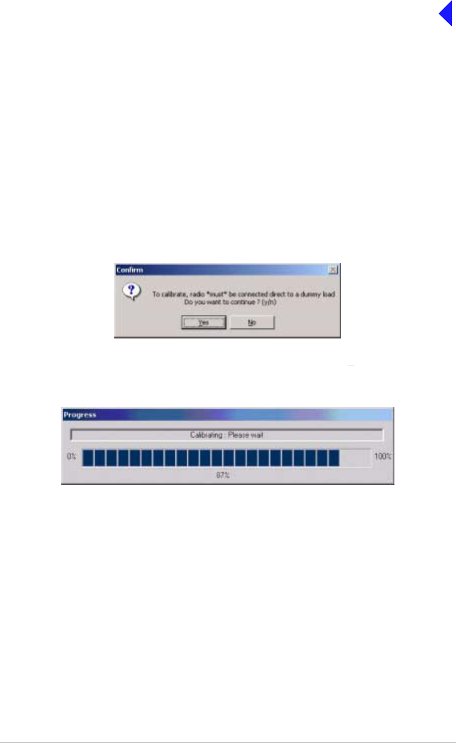
Page 26
Back to Transceiver
Main Page
To Calibrate the Transceiver
(1) Connect a dummy load via a power meter to the transceiver’s Tx/Rx Antenna connector.
(2) Remove the transceiver’s bottom cover.
(3) Using a VFP to PC interconnection lead, Park Air part number 17E12600001, connect the radio’s
front panel Headset/Microphone/Diagnostics connector to the PC’s Com Port 1 or Com Port 2
(note which Com Port is used).
(4) Run up the VFP software and check that a blank VFP screen is displayed.
(5) At the Menu Bar, click on Serial Port and select either Com 1 or Com 2. The selection must
correspond to the port used to connect to the radio.
(6) At the Menu Bar select Radio > Retrieve > All.
(7) At the Menu Bar select Radio > Calibrate. The Confirm screen will then be displayed to remind
you that a dummy load must be connected before proceeding.
(8) With the Confirm screen displayed and dummy load connected, select Yes to continue with the
calibrate routine. The Progress screen will then be displayed.
(9) When the PA Control/PA loop has been calibrated the Progress screen disappears and the VFP
screen re-appears showing a calibration complete message in the Status Information window.
(10) Gain access to the PA Control/Rx RF module and identify RV9 (this control is on the solder side
of the outer PCB adjacent to the label - see next page). From the transceiver’s front panel
AM-Voice or AM-MSK Settings screen, select PTT On.
(11) From the Settings pane of the VFP screen, note the RF power setting. Adjust RV9 until the power
meter reads this value.
(12) From the transceiver’s front panel AM-Voice or AM-MSK Settings screen select PTT Off, then
remove the power meter and dummy load. This completes the calibration routine.
(13) When there is no further requirement for using the VFP, exit the VFP software and disconnect
the radio from the PC.
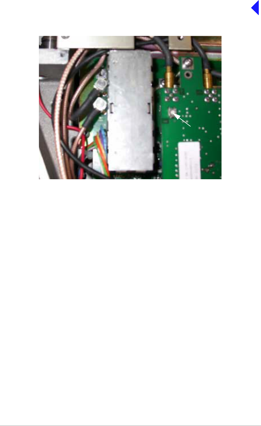
Page 27
Back to Transceiver
Main Page
RV9
Fine Power Adjust
Location of RV9

Page 28
Back to Transceiver
Main Page
Figs 1 to 10 follow
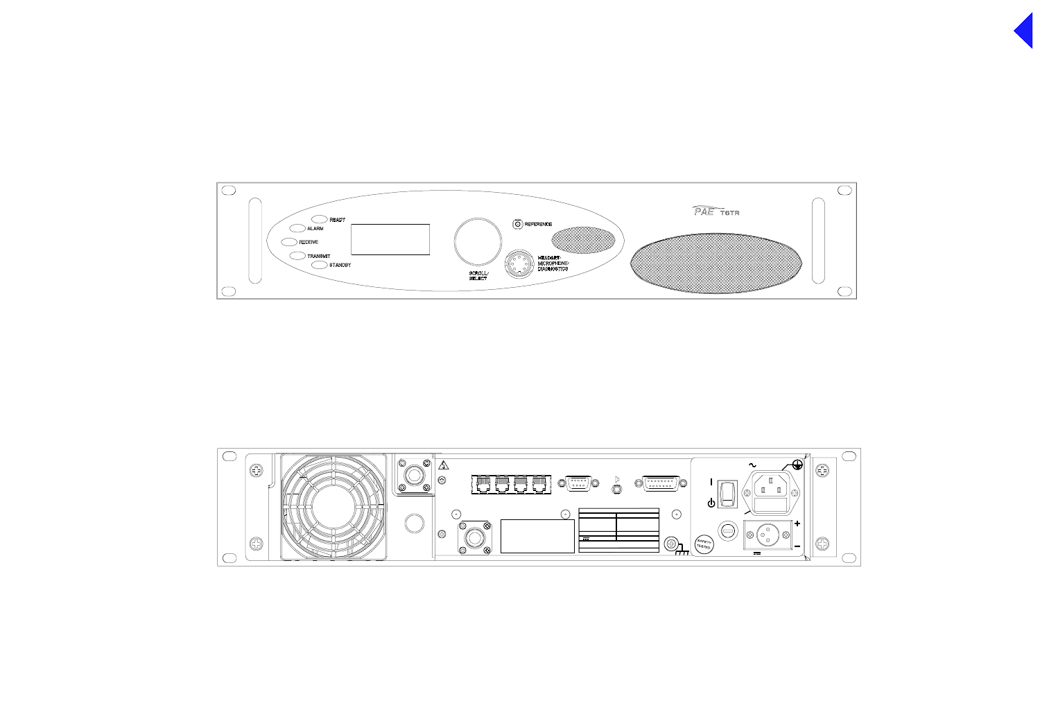
Back to Transceiver
Main Page
1
Fig 1 T6TR Front and Rear Panels
( )
INTERNALLY
SELECTABLE
RX
ANTENNA
ANTENNA
DANGER HIGH
RF VOLTAGES
CONNEC T
ANTENNA
BEFORE
USE
T1/E1 HDLC MARC
DATA MARC
AUDIO MARC FACILITIES
21. 6 - 3 2V 10A
POWER 400VA max
~ 110 - 240V ( + 10%) 4A
SEE IN STALLATION I NSTRUCTIONS BEFORE
CO NNECTING SUPPLIES
DISC ONNECT SUPPLIES WHEN N OT IN USE
DC SUPPLY
AC SU PPLY
48 - 62 Hz
FUSE F1
F15A 32V
110V - 120V T4A 125V UL
110-240V T4A 250V IEC
RATINGS
FUSE F2
DC SUPPLY
FUSE F2
FUSE F1
SUPPLY
AC SUPPLY
Front View
Rear View
Fig 1
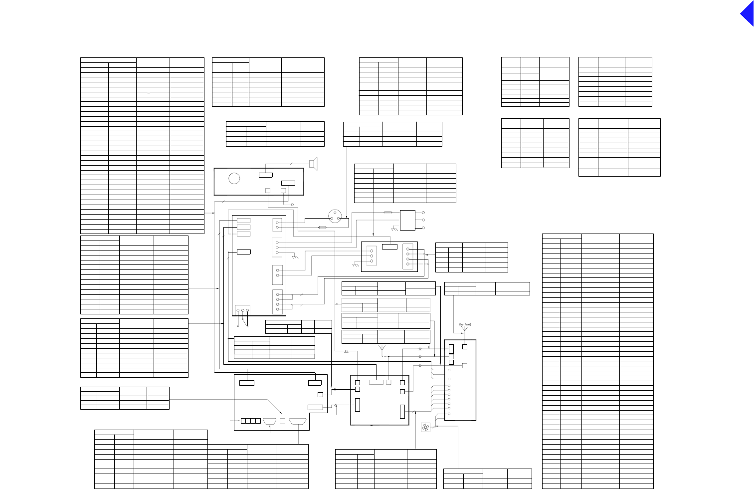
Back to Transceiver
Main Page
2
Fig 2
Fig 2 Wiring and Interconnection Diagram
CN2
Microphone/Headset/
Diagnostics
Fro nt Panel
CN3 CN1
CN4
CN5
CN6
Power Supply Regulation
CN2
1
2
2
3
1
CN3
dc Input
50
CN6
CN5
CN1
PA Co ntr ol & Rx RF
Connections
CN2- 1
Processor
450 kHz
Charact e r i st ic
Name
IF
34
***
CN3
CN4
CN2
CN10 CN1
4
Fan
2
PA
Refer ence Frequenc y
Connect i ons
Fron t Panel
-20 dBm to 0 dBm
CharacteristicName
PC CN5-1
Forward Power SenseCN8-1
Connect i ons
RF PA PA Control & RX RF 17 dBm ± 1 dB
Name Charac t er i st i c
RF Output/ Input
Connect i ons
RF PA
CN1- 1
Name Char a cteri st i c
5 to 50 W /-10 7dBm sensit ivi ty
CN4- 1 Antenna Port
(Rear Panel)
CN8
RF PA
1 dBm carrierRF Dr iveCN10 - 1CN3- 1
Connect i ons Name Characteristi c
Regulat or
Connections
RF PA
Name Characteristic
CN3- 1
CN3- 2
CN3-3 Heatsink
CN3 V Unr eg
-33 V
Ground Supply
21.6 t o 32 V
0 V
-30 V to -35 V
10
14
3
CN5CN4
Reference Fr equency
(Front Panel)
CN4- 1
CN3
CN2
CN4
CN5
CN7
CN9
CN6
(-30.5 dBc ± 0.9 dB)
3Loudspeaker
CN8-1
CN11
CN8 CN7
CN13
Sensi tivit y: - 107dBm
Max. cont inuous: 5 V rms
RF PA
CN13- 1 Rx InputCN7- 1
Connect i ons Name Characteristic
CN12
CN11
(Rear
Panel )
CN14
CN3 CN4
CN7
Facilities
CN5
MARC
CN6
Processor
*
**
CN2
CN1
A B C D
CN8
0 to 4 V / 0 to 6VFrequency TrimCN1-14 CN1-14
CN1-50
CN1-48
CN1-49
CN1-47
CN1-45
CN1-46
CN1-44
CN1-43
CN1-42
CN1-41
CN1-15
CN1-16
CN1-21
CN1-22
CN1-23
CN1-17
CN1-19
CN1-18
CN1-20
CN1-24
CN1-25
CN1-30
CN1-26
CN1-29
CN1-28
CN1-27
CN1-31
CN1-32
CN1-33
CN1-34
CN1-36
CN1-35
CN1-37
CN1-40
CN1-39
CN1-38
CN1-50
CN1-45
CN1-43
CN1-44
CN1-47
CN1-46
CN1-49
CN1-48
CN1-28
CN1-42
CN1-41
CN1-38
CN1-39
CN1-36
CN1-37
CN1-40
CN1-32
CN1-31
CN1-29
CN1-30
CN1-34
CN1-33
CN1-35
CN1-21
CN1-24
CN1-23
CN1-22
CN1-26
CN1-27
CN1-25
CN1-17
CN1-16
CN1-15
CN1-20
CN1-19
CN1-18
TTL
TTL
TTL
TTL
TTL - Low OCXO fitted
TTL - High fan on
TTL
BIT Cont rol 3
BIT Cont rol 2
Step Si ze
V/U Det ect
TR Detect
Reser ved
OXCO Fi t ted
Fan Enable
TTL
TTL
TTL
TTL
TTL
TTL
0 to 2.5 V
10 mV / °C
10 mV / °C
0 to 5 V (5 V 3dB back off)
TTL
TTL
TTL
TTL
TTL
BIT Loop Corre ct
BIT Sy nth Lock
BIT Open Loop
BIT VSWR OK
BIT Cont rol 1
BIT Cont rol 0
Reflected Power
PA Temperature
Aut o Level Cont rol
Ext ern al VSWR
PAC Temperatur e
Nar r o w/ Wi de
Tx Key
TTL
TTL
TTL
TTL
0 V
TTL
0 V
TTL pull up active low
TTL
TTL
TTL
TTL
Filter 3
Dat a
Phase Load
Clock
Synth Load
Ground
Filter 4
Filter 0
Filter 2
Filter 1
Ground
Power Down
Tx/Rx Detect
CN1-10
CN1-13
CN1-12
CN1-11
Processor
CN1- 7CN1- 7
CN1- 9
CN1-10
CN1- 8
CN1-12
CN1-13
CN1-11
CN1- 9
CN1- 8
CN1- 2
CN1- 3
CN1- 1
CN1- 5
CN1- 6
CN1- 4
CN1- 6
CN1- 5
CN1- 4
CN1- 2
CN1- 3
CN1- 1
Connecti ons
0 to 2.5 V
0 V
±2.5 V
±2.5 V
0 to 2.5 V
0 to 2.5 V
0 to 2.5 V
0 V
0 V
0 V
0 V
0 V
0 V
Ground
Ground
Q
Ground
Ground
BIT Q Moni tor
BIT I Monitor
RF AGC
I
Ground
IF AGC
Ground
Ground
Name Characterist ic
***
Reser ved
RF PA Bias Disable
TTL
TTL
*
6
7
8
2
4
3
5
Pin Number
1
Name
CN7A
n/c
n/c
n/c
RTIP
TRING
n/c
TTIP
RRING
*
6
7
8
2
4
3
5
Pin Number
1
Name
CN7B
HDLC CL B
HDLC CL A
Unregulated Supply
HDLC Rx B
HDLC Tx B
HDLC Rx A
HDLC Tx A
Ground
6
7
8
2
4
3
5
Pin Nu mber
1
Name
CN7C
n/c
n/c
Unregulated Supply
Data Rx B (Data In +)
Data Tx B (Data Out +)
Data Rx A (Data In -)
Data Tx A (Data Out -)
Ground
*
6
7
8
2
4
3
5
Pin Nu mber
1
Name
CN7D
Line I n -
Antenna Change Over/PTT/
Fast ATR Output (T6T)
Squelch Output (T6TR)
Line I n/Out +
PTT I nput
Line I n/Out -
Line I n +
Ground
*
Charact e r i st ic
Characteristic
Characteristic
Charact e r i st ic
+10 dBm in to 600W
+10 dBm in to 600W
0 V
0 V or +10 V to +50 V or
-10 V to 5 0 V at 5mA
+20 dBm to -20 dBm 600R
+20 dBm to -20 dBm 600R
ANSI T1.403- 1995 (T1),
ITU-T: G.703 (E1)
ANSI T1.403- 1995 (T1),
ITU-T: G.703 (E1)
0V
21.6V to 32V
RS 422
RS 422
RS 422
RS 422
PNP open collector grounding
transistor
Solid- stat e relay gr ounding
output
0V
RS 422
RS 422
RS 422
RS 422
RS 422
RS 422
21.6V to 32V
CN6- 7 7
CN6- 8
CN6- 9 9
8
Processor
CN6- 1
CN6- 2
CN6- 3
CN6- 5
CN6- 6
CN6- 4
**
4
6
5
3
1
2
MARC Por t
Connections
Data RX A - Data In - RS422
RS422
RS422Data TX B - Data Out +
Data TX A - Data Out -
RS422
0 V or +10 V to +50 V or
Fused 50 0mA, 21.6 to 32 V
+20 dBm to -20 dBm 600R
Characteristic
PTT ( Mute)
Data RX B - Data In +
Unregulated Supply
Line -
Line +
Ground 0 V
Name
+20 dBm to -20 dBm 600R
-10 V to 50 V at 5mA
Microphone/
Fron t Panel
Connect ions Name Characteristi c
CN2-1 1 Ground - Microphone 0 V
CN2- 6
2 Tr ansmit Dat a RS232
CN2- 3 3 MIC PTT
CN2-4 4 Receive Data RS232
CN2-5 5 Sidetone ( Headset Dri ve) 3 Vac pk-pk, 200R
CN2- 2
6 Microphone Input
CN2-7 7 Ground 0 V
Diagnostics
0 V = PTT, 5 V pull -up = not PTT
6k8 i nput i mpedance, 5mV sens iti vity
Fron t PanelProcessor
Connections Name Characteristic
CN4-1
CN4-2
CN4-3
CN4-4
CN1-1
CN1-2
CN1-3
CN1-4
LED Alarm
LED Ready
LED Standby
LED Tx (LED Rx)
LCD RS
Open coll ector (5mA)
CN4-5
CN4-6
CN4-7
CN4-8
CN4-9
CN4- 1 0
CN4- 1 1
CN4-12
CN4-13
CN4-14
CN4- 1 6
CN4-17
CN4-18
CN1-20
CN1-19
CN4- 1 5
CN1-25
CN4-24
CN4- 2 3
CN1- 2 2
CN1- 2 1
CN1- 5
CN1-24
CN1-23
CN1-16
CN4-19
CN4-22
CN4- 2 1
CN4-20
CN1-18
CN1-17
CN1-6
CN1- 7
CN4-25
LCD R/W
LCD Backli ght
Transmit Data
+5 V Suppl y
-5 V Suppl y
Ground
+15 V Suppl y
Ground
Mi c PT T
LED RX
5 V pul l-up
TTL
TTL
TTL
TTL
0 V
-5 V
TTL
TTL
+15 V
LCD Enable
Dat a 3
Dat a 2
Dat a 7
Dat a 6
Dat a 5
Dat a 4
RS232
+5 V
0 V
Rec eive Data
0 V=PTT,5 V p ull -up=PTT
Turn +
TTL
TTL
TTL
RS232
Turn -
Sidetone (Headset Drive) 3 Vac pk-pk
Loudspeaker Amp Dri ve
Ground
Mi c I np ut
Ground 0V
1.6V p-p maximum
0V
2V p-p maximum
Push
Ground 0 V
CN1- 26CN4-26
CN1- 27CN4-27
CN1-31
CN1-29
CN4-28
CN1- 3 0
CN4-31
CN4-29
CN1- 28
CN4-30
CN4-33
CN1-34
CN1-33
CN4-34
CN1-32CN4-32
Open coll ector (200mA)
Open coll ector (5mA)
Open coll ector (5mA)
Open coll ector (5mA)
Dat a 1
Dat a 0
TTL
TTL
CN1- 1 2
CN1- 1 3
CN1- 1 4
CN1- 1 5
CN1- 8
CN1- 9
CN1- 1 0
CN1- 1 1
5 V pul l-up
5 V pul l-up
Open coll ector (5mA)
CN3- 1 4
CN3- 1 3
CN3- 1 2
CN3- 1 1
CN3- 1 0
CN4- 1 4
CN4-13
CN4-12
CN4- 11
CN4- 1 0
n/c
Remote on/off
V Unreg
V Unr eg
dc Detect
CN3- 9
CN3- 8
CN3- 7
CN3- 6
CN3- 5
CN3- 4
CN3- 3
CN3- 2
CN3- 1
Connect i ons
CN4- 6
CN4- 9
CN4- 8
CN4- 7
CN4- 5
CN4- 4
CN4- 3
CN4- 2
CN4- 1
Regulat ion
ac Detect
-15 V Suppl y
Groun d
+5 V Suppl y
+15 V Supply
Processor
Name Char act erist i c
+15 V Supply
-15 V Suppl y
+5 V Suppl y
Groun d
-15 V
21.6 to 32 V
21.6 to 32 V
Open col lect or
> 20 mA into 250R
+15 V
+5 V
+15 V
-15 V
+5 V
0V
0V
CN6- 7
CN6- 6
CN6- 1 0
CN6- 9
CN6- 8
CN5- 1 0
CN5- 9
CN5- 6
CN5- 7
CN5- 8
-15 V Suppl y
ac Detect
dc Detect
-15 V Suppl y
Groun d
-15 V
-15 V
0V
Connect i ons
CN6- 5
CN6- 4
CN6- 3
CN6- 2
CN6- 1
CN5- 2
CN5- 4
CN5- 3
CN5- 5
Regulation
CN5- 1
Name
+5 V Suppl y
+15 V Supply
+5 V Suppl y
+15 V Supply
Groun d
Characteristic
+15 V
+5 V
+5 V
0V
+15 V
0V = on, open collector = off
n/c
n/c
n/c
Processor
CN8 Ri ng
CN8 T ip External Speaker Dri ve
External Speaker Dr ive 3 Vac pk- pk max
Characteristic
Connecti ons Name
Ext ernal Speaker
1
2
CN8 Sleeve Ground 0 V
3
3 Vac pk-pk max
EXT SPKR
T1/E1
MARC AU DIO
MARC DA TA
HDLC
Unregulated SupplyCN5-9 9 Fused 300mA 21.6 to 32 V
Name
Reser ved
Tape Out put
CN5-14
CN5-15
CN5-13
CN5-12
CN5-11
14
15
13
12
11 BIT Int errupti ve Test
RSSI
Ready Output
Facilities
Connections
CN5-10
Processor
10 Inhibit
Open coll ector , 0 V = Ready
-10 dBm. 100R
TTL pull-up active low
Charac t er i st i c
n/c
TTL pull-up active low
Potenti al range 0 V to 10 V
CN5-4
CN5-6
CN5-7
CN5-5
7
5
6
4
Open col lector; 0 V = Tx
TTL pul l-up act ive low
Open col lector; 0 V = Tx
Squelch Defeat
Antenna Change Over
Ext ern al VSWR
CN5-3
CN5-2
CN5- 1
Processor
Connecti ons
Facilities
2
3
1
CharacteristicName
E Bit
PTT
Ground 0 V
GroundCN5-8 8 0 V
(Squelch)
Antenna Change Over (Squelch)
TTL pul l-up act ive low 50 W = -3.95 V
Charact e r i st ic
TTL - High for fan on
TTL - High for bias on
PA Bi as Enabl eCN2-3
CN2- 5
CN2- 4
Reflected Power
Fan Enable
RF PA
Connections Name
CN2- 6
CN2-2
CN2- 1 PA Temperat ure
Dr ive Det ect
10 mV/°C + 0.5V
0.5 V for +10 dBm
CN4
CN9
CN5
CN7
CN2
CN12 PA Current Detect 0.1V per Amp
RF PA
PA Heatsi nk
CN6 Fan Control
Ground 0V
24 V
CharacteristicConnections Name
Fan
Fan
Connecti ons Name Char acteristic
Fron t Panel
CN3-1 Loudspeaker Loudspeake r output
CN3-2 Loudspeaker Ground 0 V
CN3-3 n/c n/ c
2V p-p maxi mum Input-1 CN2- 2 Fused 21.6 to 32 V
dc Input
Input -2 CN2- 1 Ground Supply 0 V
Connections
DC Input Regulation
Name Characteristic
Input-3 n/c n/c
PA Control & RX RF
PA Control & RX RF
PA Control & RX RF
PA Control & RX RF
PA Co ntr ol & RX RF
PA Co ntrol & RX RF
PA Co ntr ol & RX RF
13
(Rear Panel)
CN7
2
Supply
(shown in
off position)
1
3
2
CN1
4
L
N
Eac Input
CN1-3
CN1-2
CN1- 1
Regulator
CN1- 3
CN1- 2
CN1- 1
PSU
Connections
Ground Suppl y
Name Cha ra ct er is ti c
CN1-4
0 V
V Unreg
Mai ns IEC
Connector
Filtered/
Fused
CN8 1 L
2 N
3 E
Power Supply
1
CN1
4
3
2
L
N
E
CN1-4
CN4
CN9 L
N
0 V
Charact e r i st ic
0 V = on
o/c OK
PSU OKCN6- 3
CN6- 5
CN6- 4
0 V
PSU off
PSURegulation
Connections Name
CN6- 6
CN6-2
CN6- 1 0 V
PSU OK
10 mV/°C + 0.5V
0 V OK
CN4- 3
CN4- 1 PSU of f PSU off 0V = 0ff
2
2
(Rear Panel)
Ground Suppl y 0 V
29 V
V Unreg 29 V
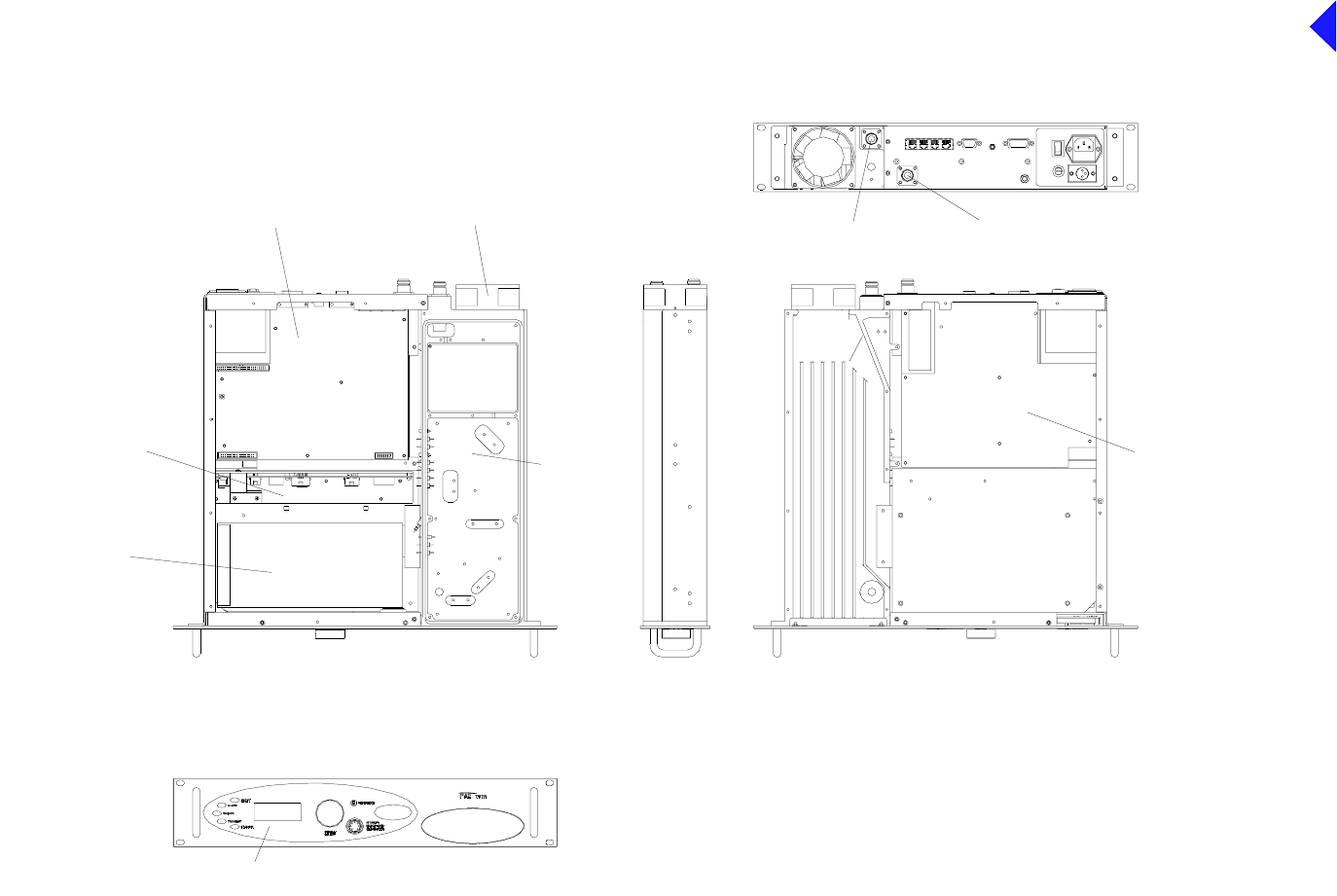
Back to Transceiver
Main Page
3
Fig 3
Regulation Module
Power Supply
T6 Series 2 VHF Transceiver
Module Location Diagram
VHF TR PA Control
& RX RF Module
VHF TR RF PA
Processor Module
Front Panel Module
Module
Transmit Antenna Connector Receive Antenna Connector
Top view - Top Cover removed View on underside - Bottom Cover removed
Fan
Fig 3 Module Location Diagram
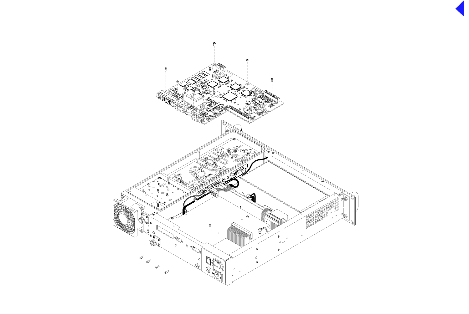
Back to Transceiver
Main Page
4
Fig 4
Fig 4 Processor Module - Removal and
Refitting Detail
PA CN8
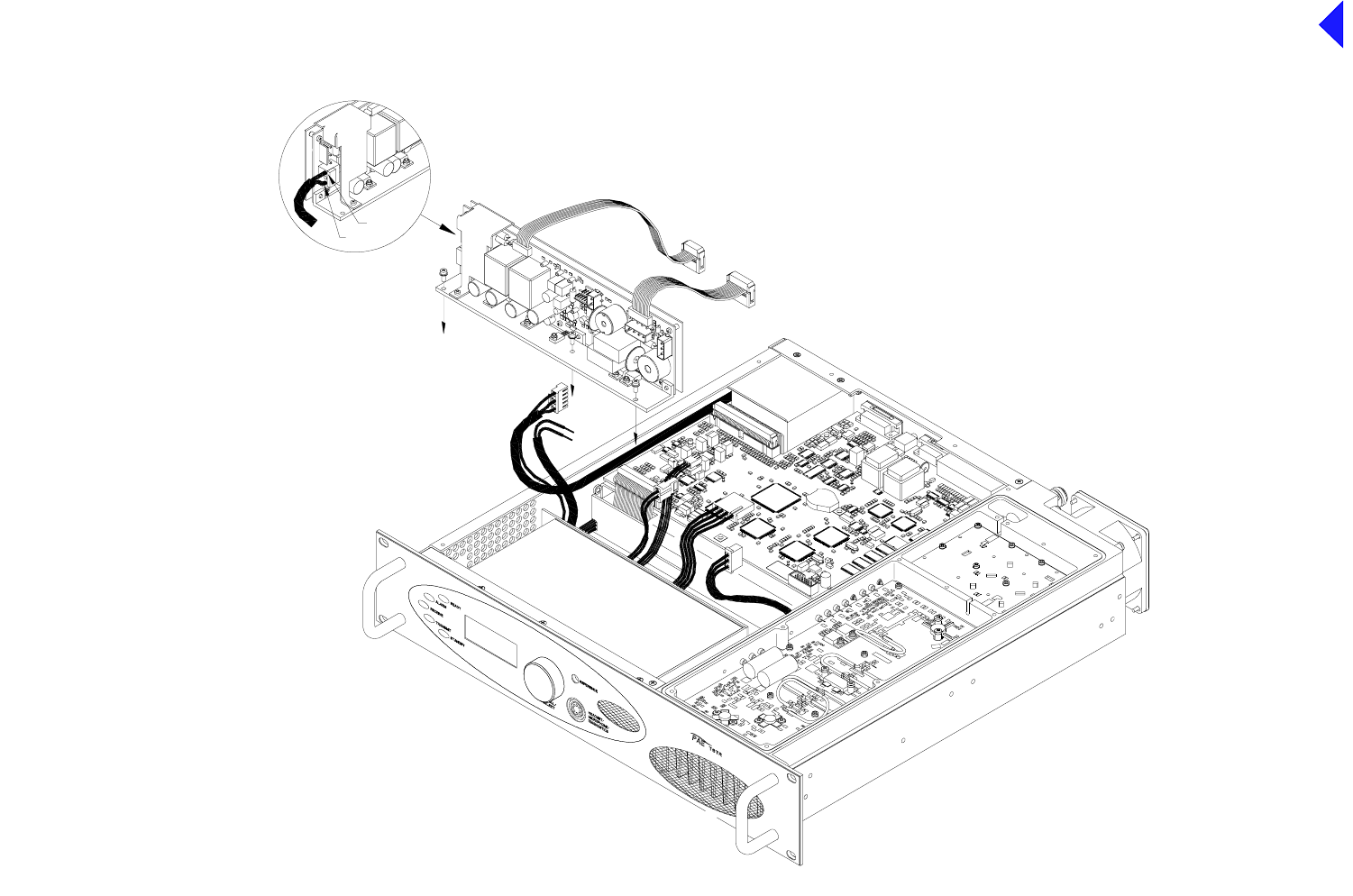
Back to Transceiver
Main Page
5
Fig 5
Fig 5 PSU Regulator Module - Removal and
Refitting Detail
Blue (N)
Brown (L)
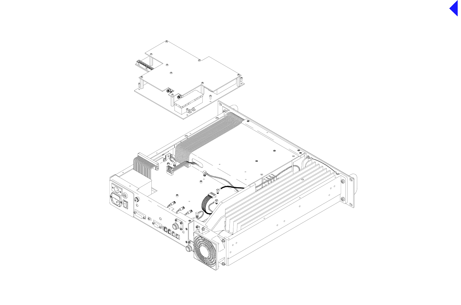
Back to Transceiver
Main Page
6
Fig 6
Fig 6 PA Control/Rx RF Module - Removal and
Refitting Detail
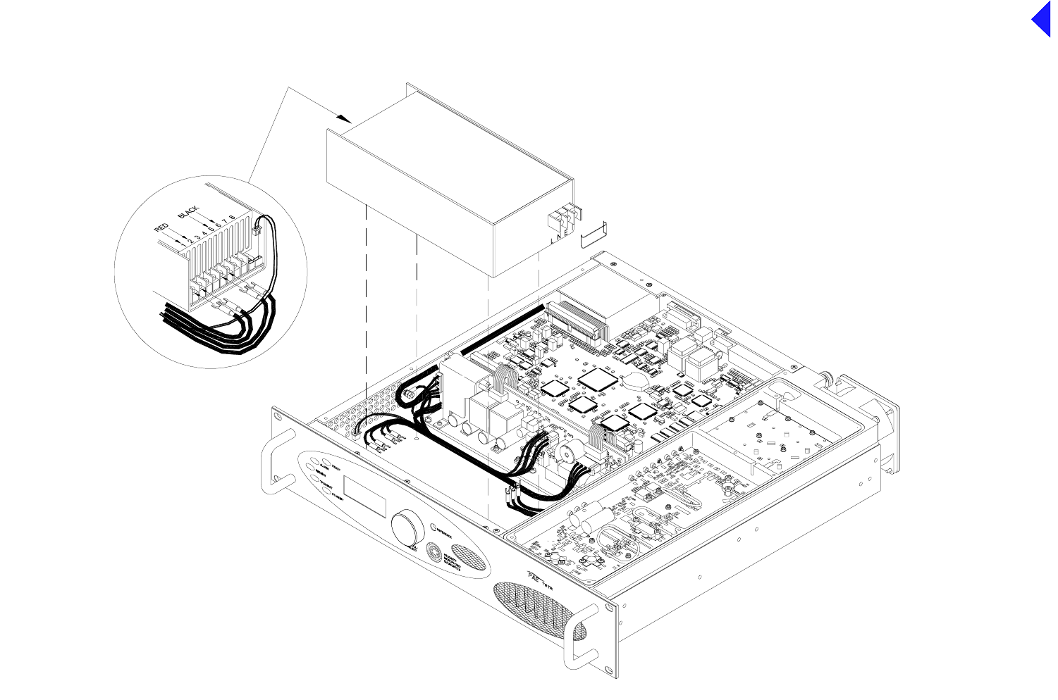
Back to Transceiver
Main Page
7
Fig 7
Fig 7 Power Supply - Removal and
Refitting Detail
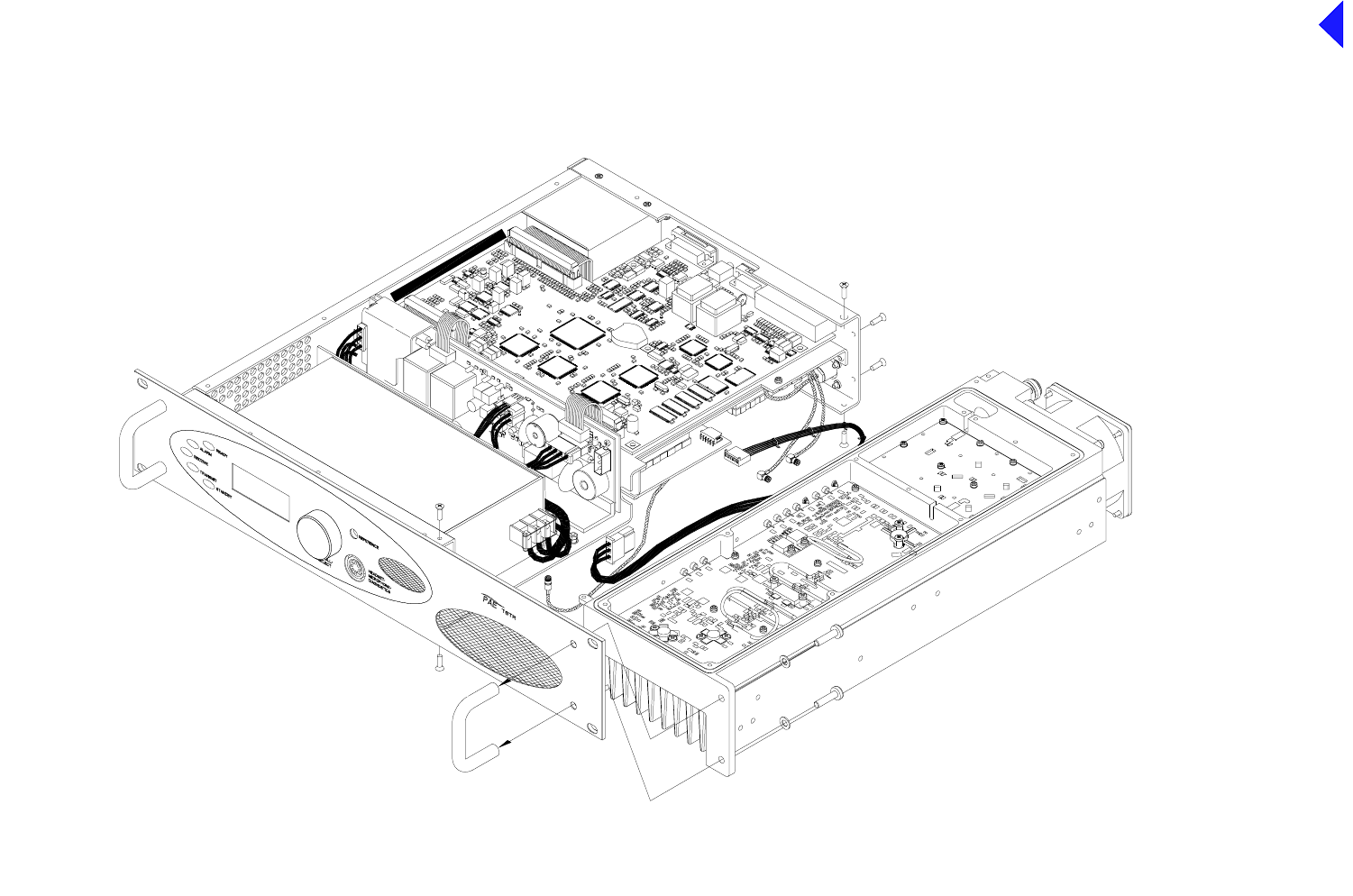
Back to Transceiver
Main Page
8
Fig 8
Fig 8 PA Module - Removal and
Refitting Detail
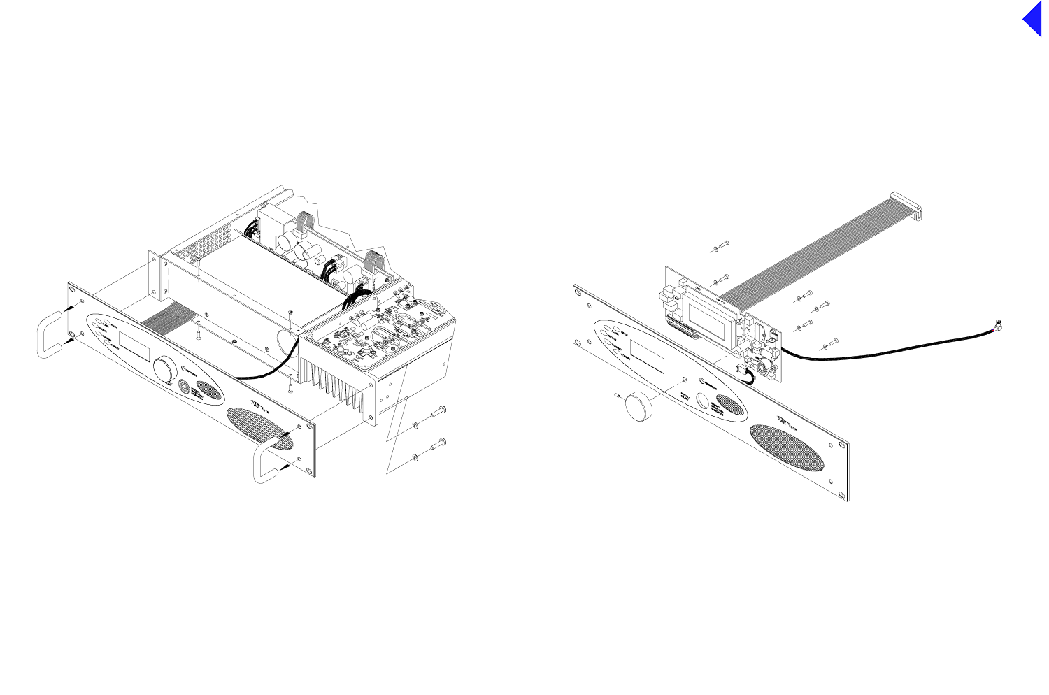
Back to Transceiver
Main Page
9
Fig 9
Fig 9 Front Panel Assembly PCB - Removal
and Refitting Detail
Diagram A Diagram B
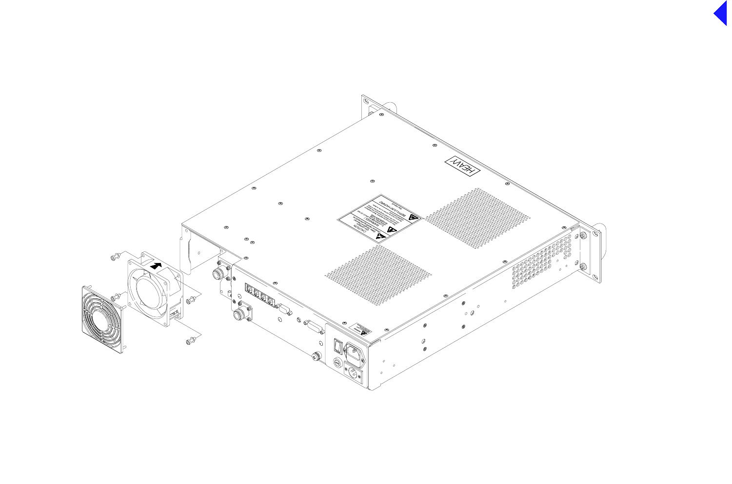
Back to Transceiver
Main Page
10
Fig 10
Fig 10 Cooling Fan - Removal and
Refitting Detail