ParkerVision D2D00003 2.4 GHz WIRELESS LAN ROUTER User Manual d2d access point manual rev 030104a indd
ParkerVision Inc 2.4 GHz WIRELESS LAN ROUTER d2d access point manual rev 030104a indd
UserManual.wiki
>
ParkerVision
>
D2D00003 User Manual
>
USERS MANUAL 1
Contents
1.
USERS MANUAL 1
2.
USERS MANUAL 2
USERS MANUAL 1
Navigation menu
Upload a User Manual
Namespaces
Wiki Guide
HTML
PDF
Info
Views
User Manual
Discussion / Help
Navigation

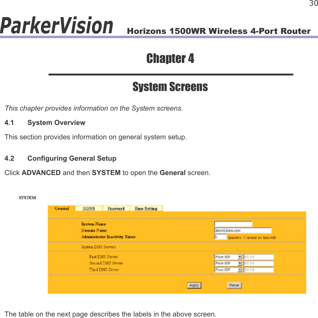
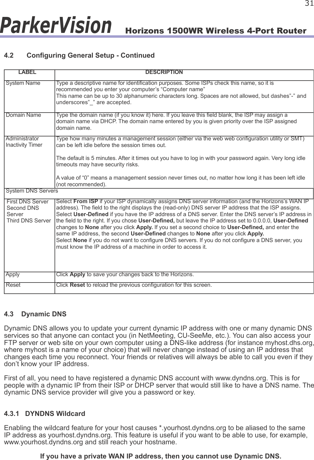
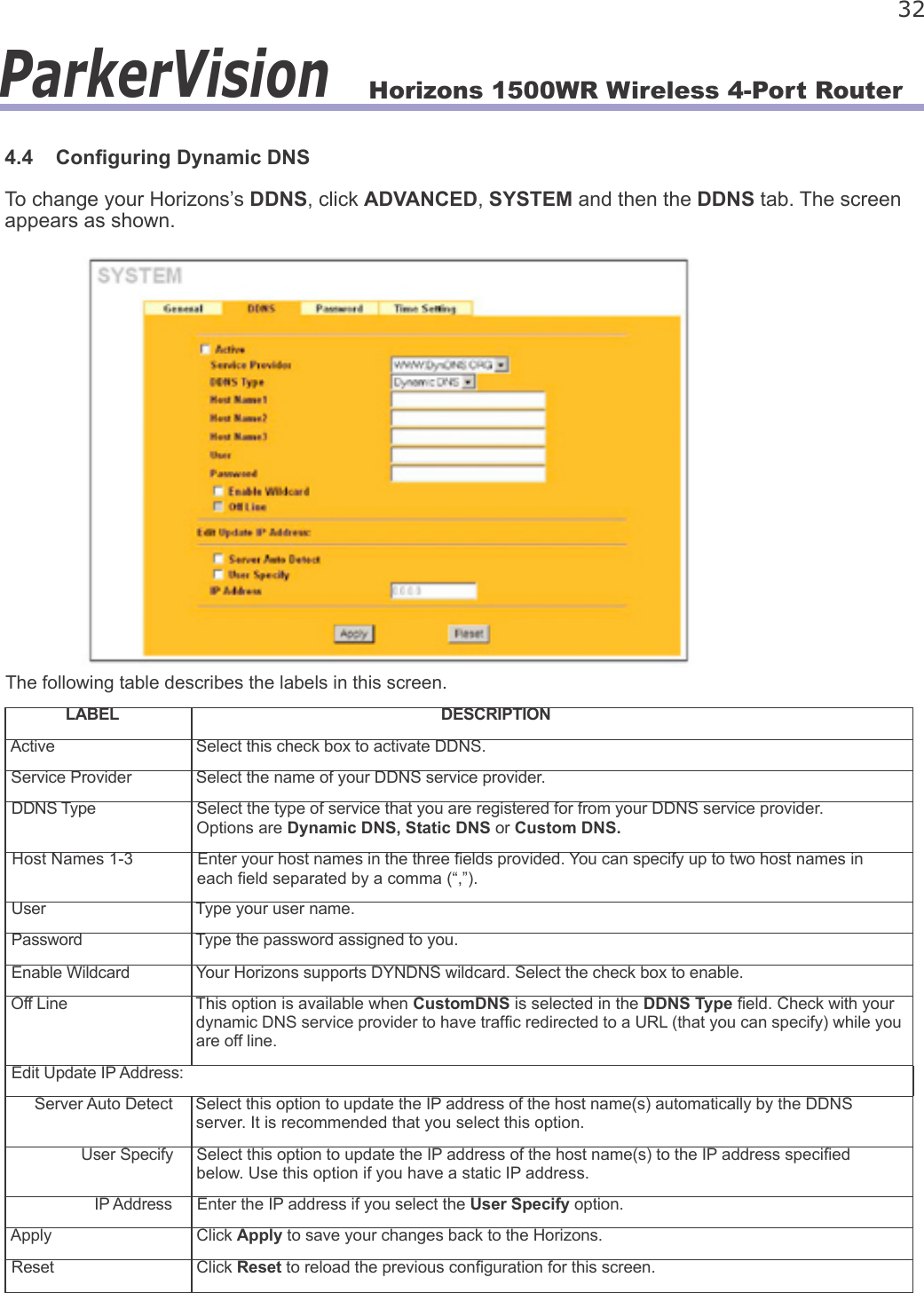
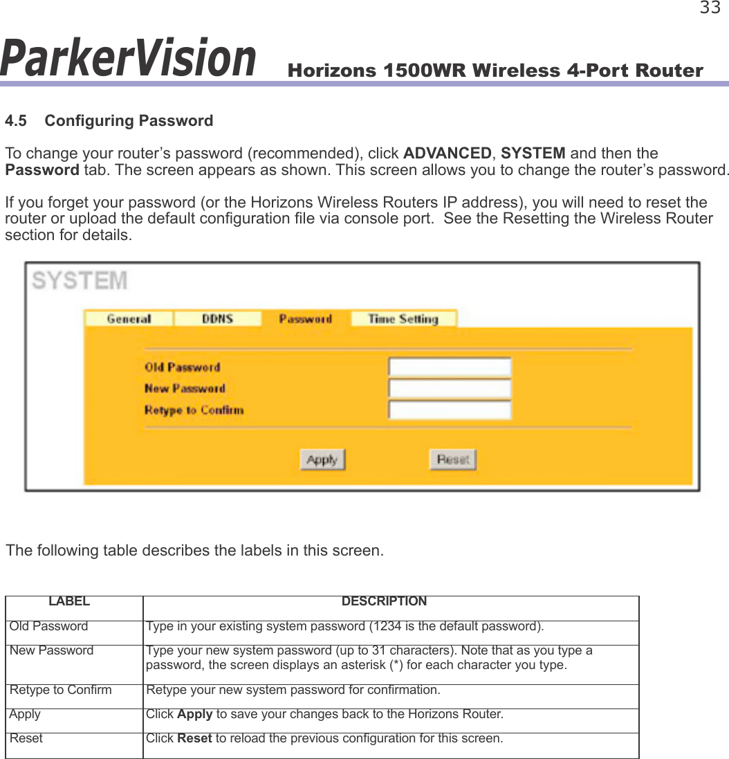
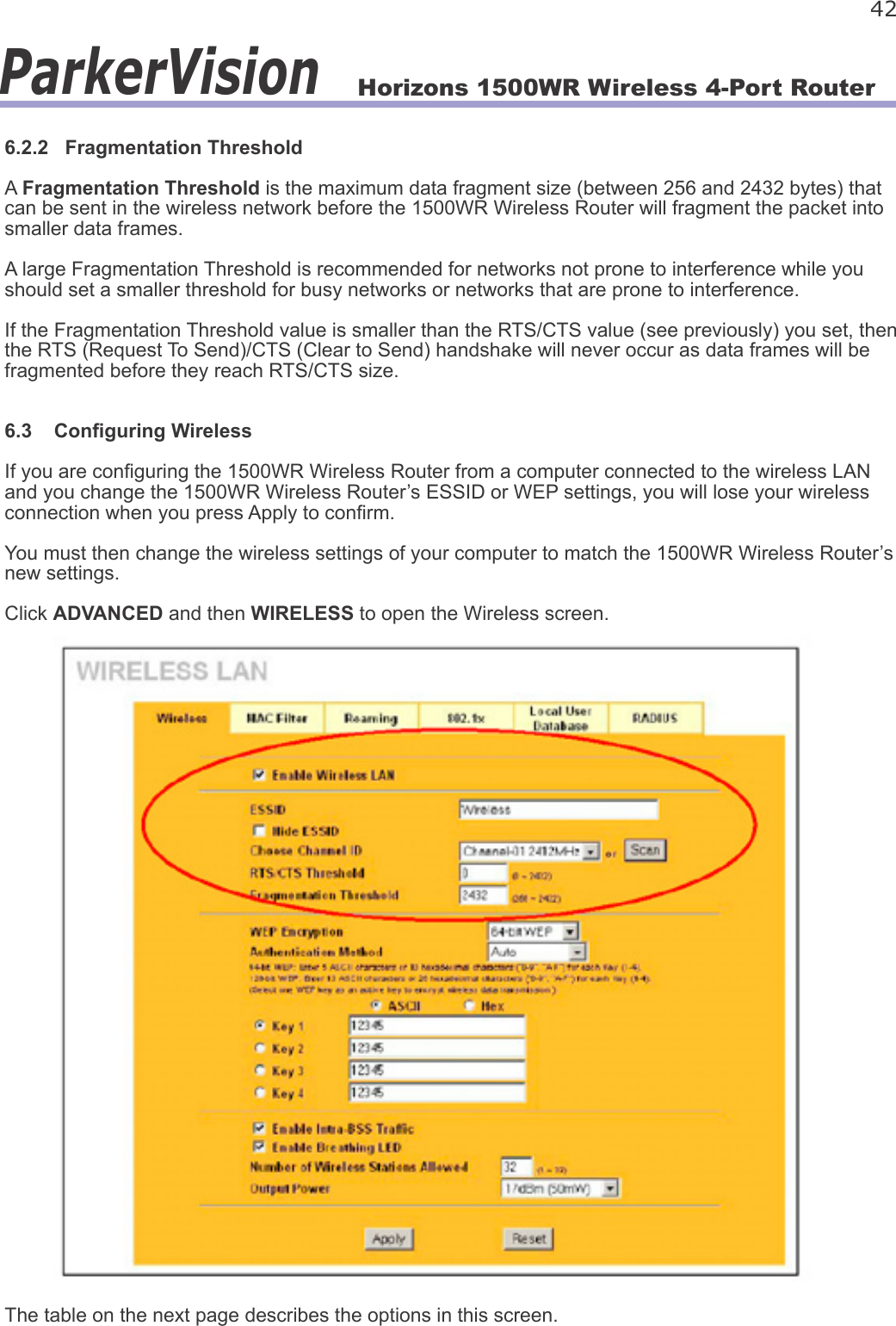
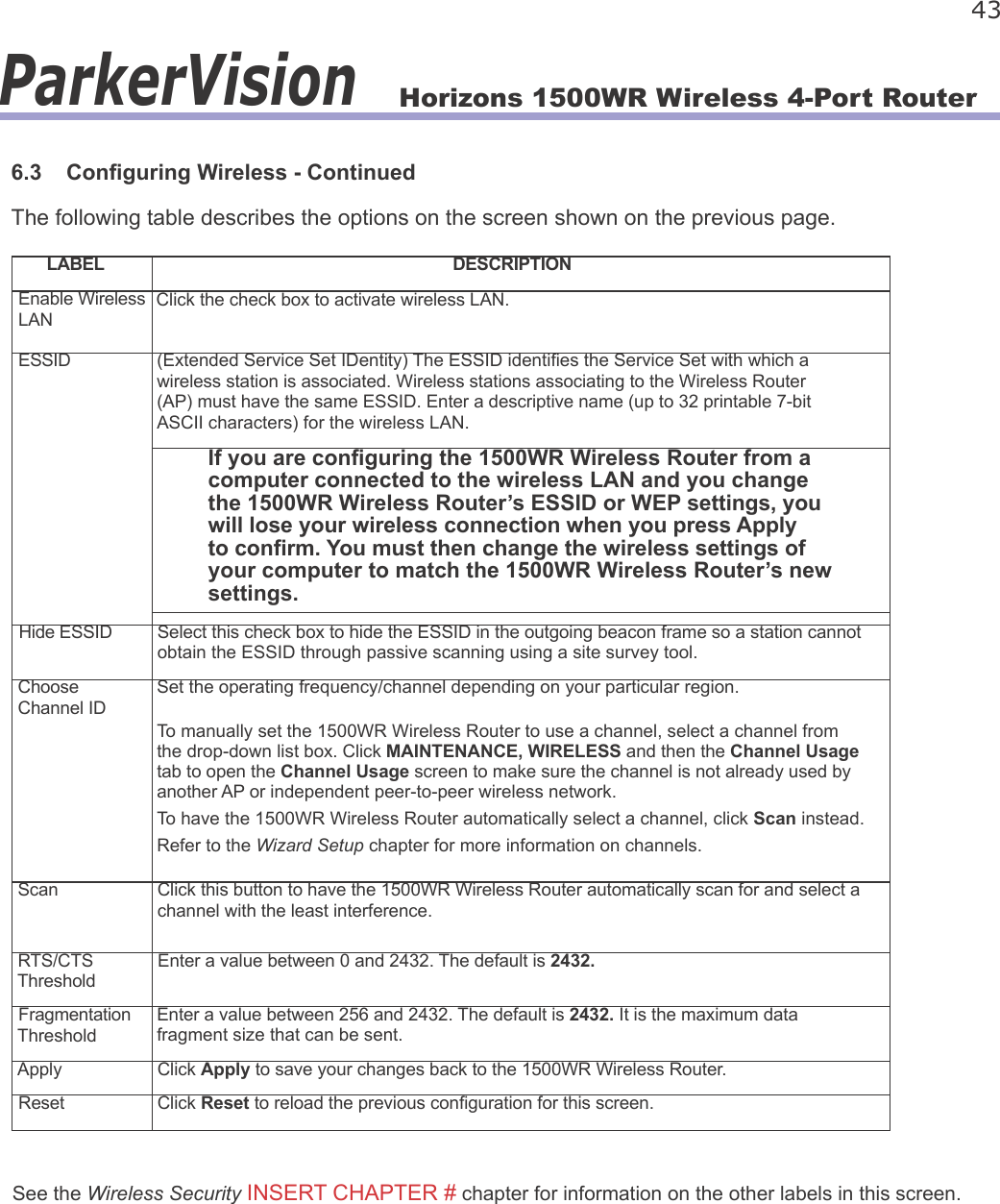
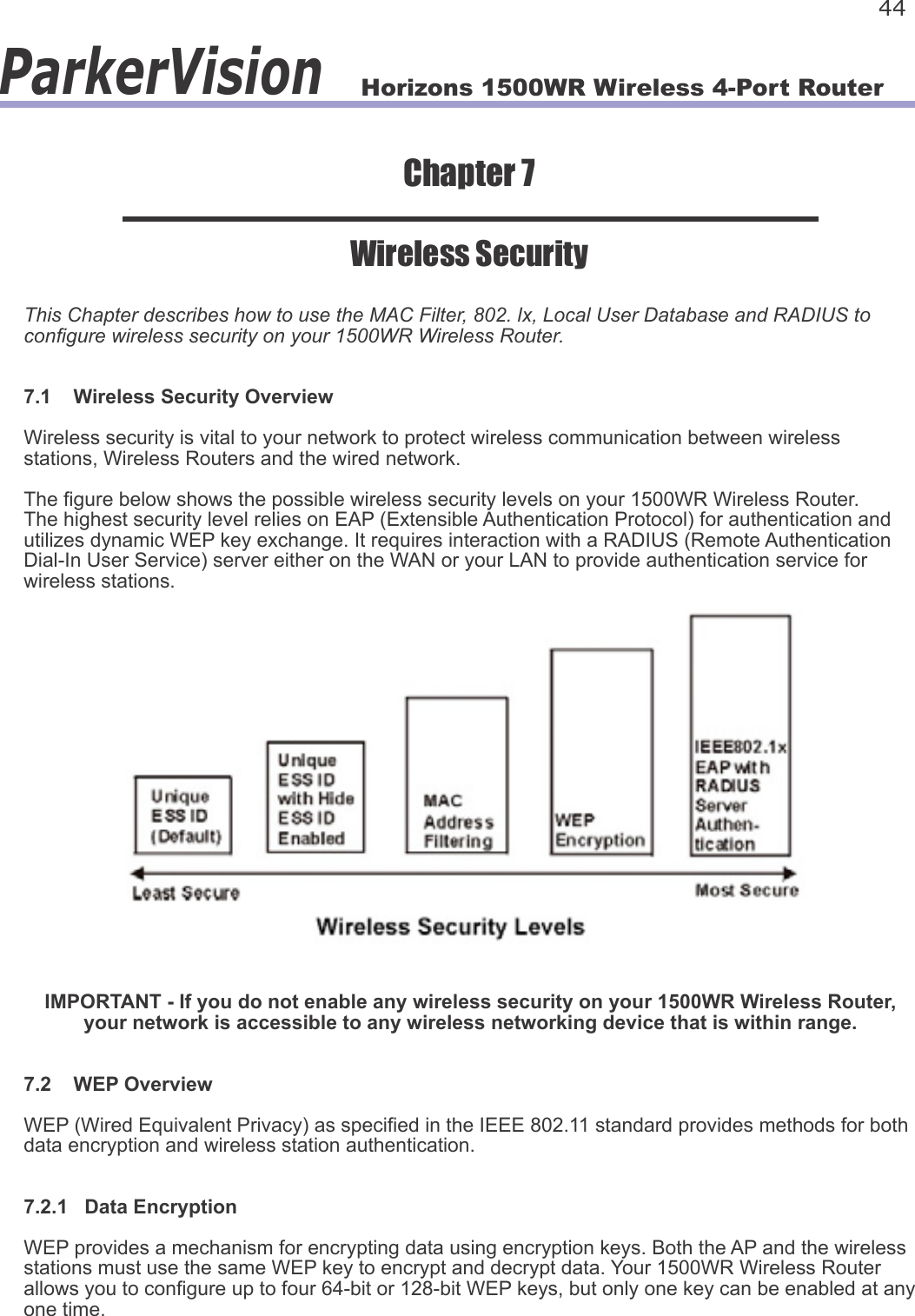
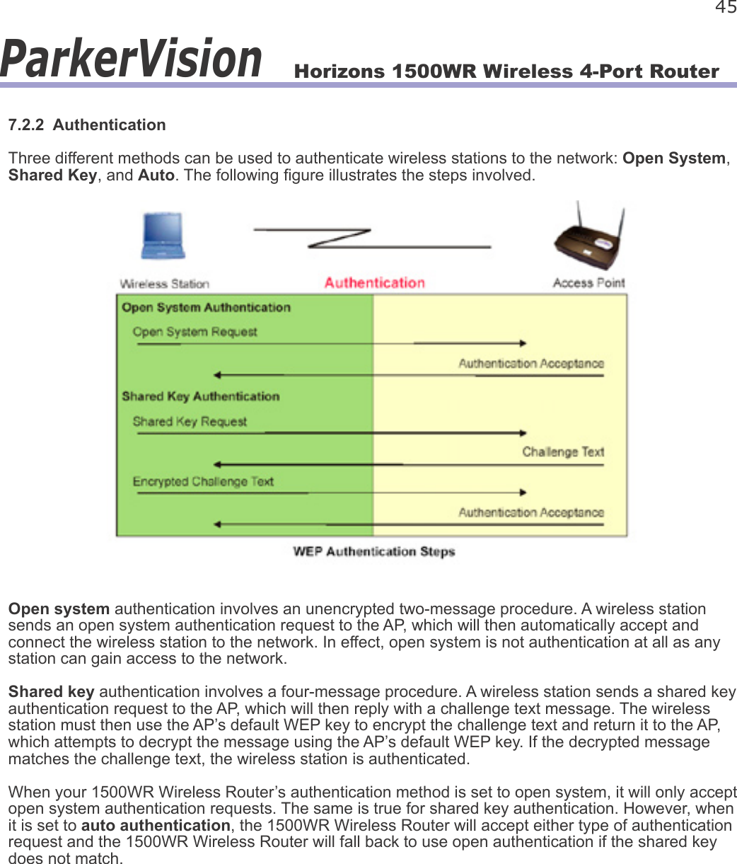
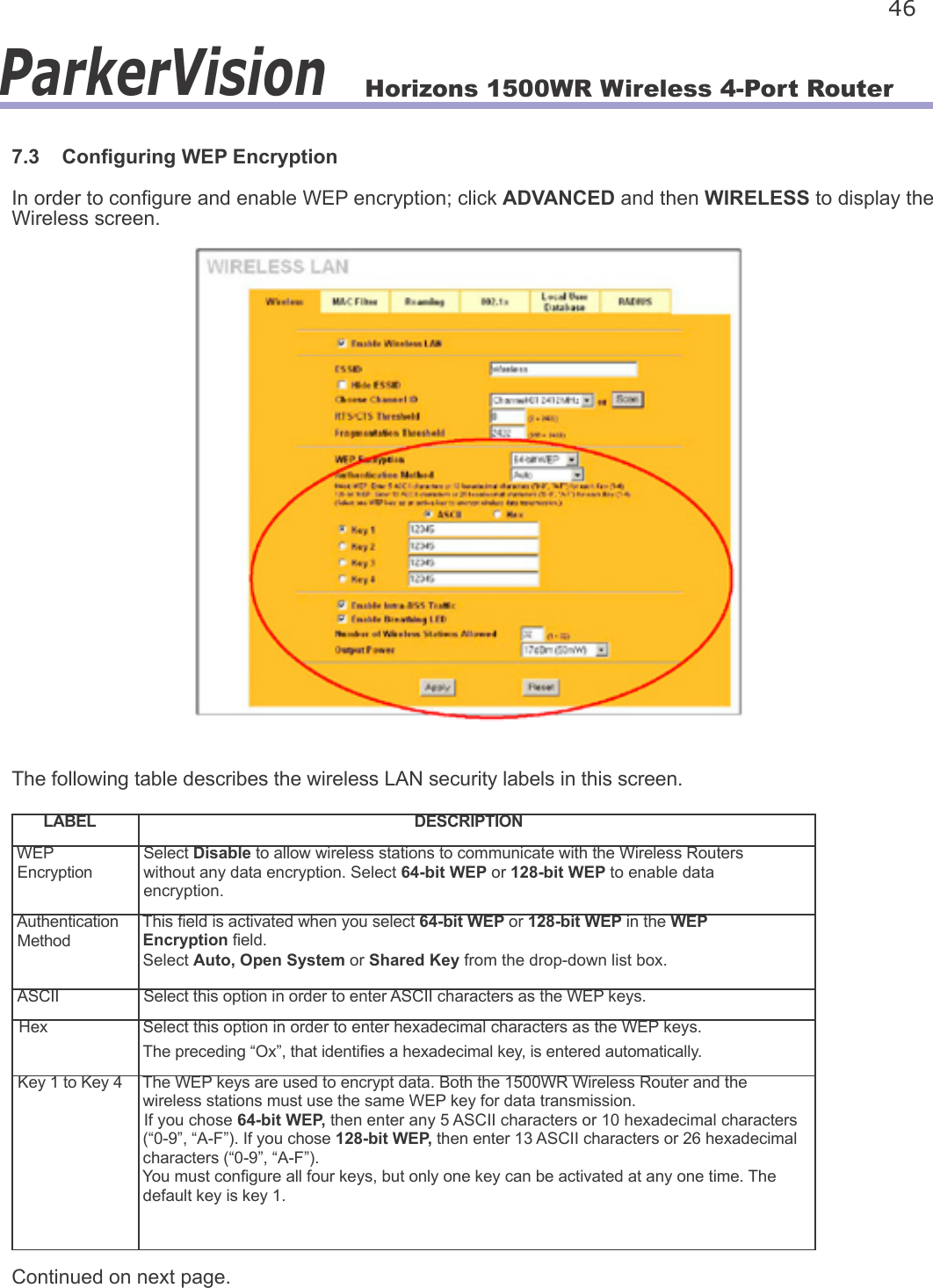
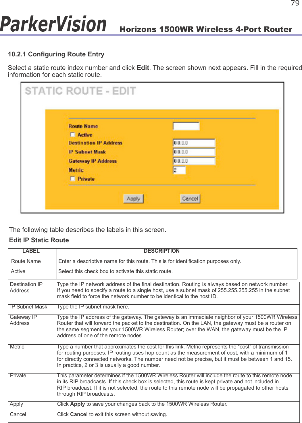
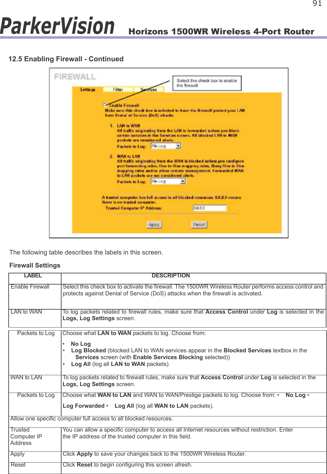
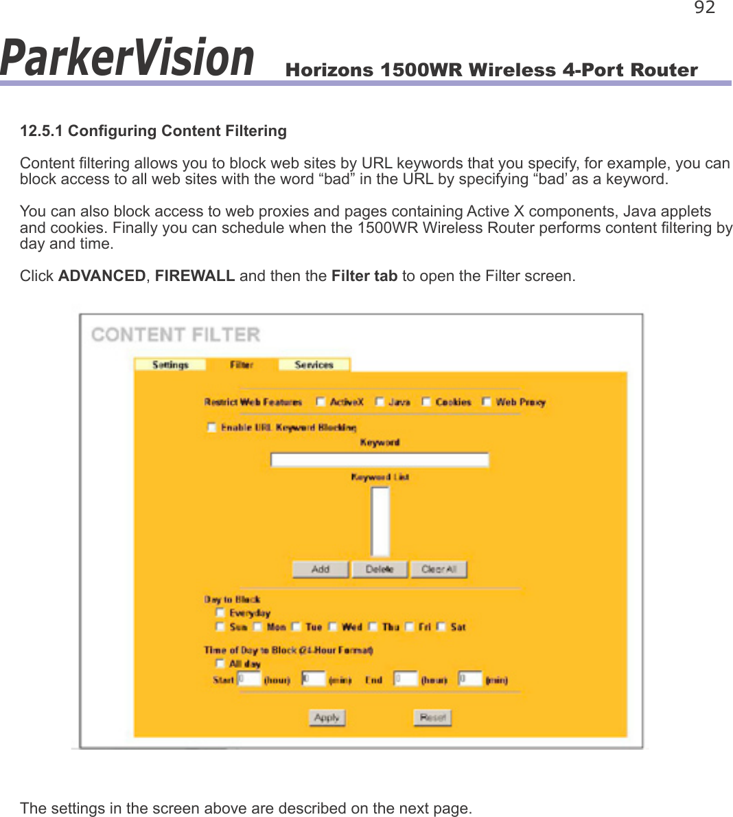
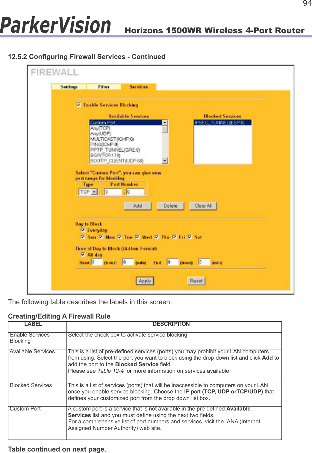
![Horizons 1500WR Wireless 4-Port Router 17ParkerVision2.3.2 Uploading a Conguration File via Console Port - ContinuedStep 6. Click Transfer, then Send File to display the following screen.Step 7. After successful rmware upload, enter “atgo” to restart the 1500WR Wireless Router.2.4 Navigating the 1500WR Wireless Router Web Web Conguration UtilityThe following summarizes how to navigate the web Web Conguration Utility from the MAIN MENU screen. Follow the instructions you see in the MAIN MENU screen or click the IBs] icon (located in the top right corner of most screens) to view online help.](https://usermanual.wiki/ParkerVision/D2D00003.USERS-MANUAL-1/User-Guide-404305-Page-17.png)