ParkerVision D2D00003 2.4 GHz WIRELESS LAN ROUTER User Manual d2d access point manual rev 030104a indd
ParkerVision Inc 2.4 GHz WIRELESS LAN ROUTER d2d access point manual rev 030104a indd
Contents
- 1. USERS MANUAL 1
- 2. USERS MANUAL 2
USERS MANUAL 2
Horizons 1500WR Wireless 4-Port Router
107
ParkerVision
13.8 Conguring Security
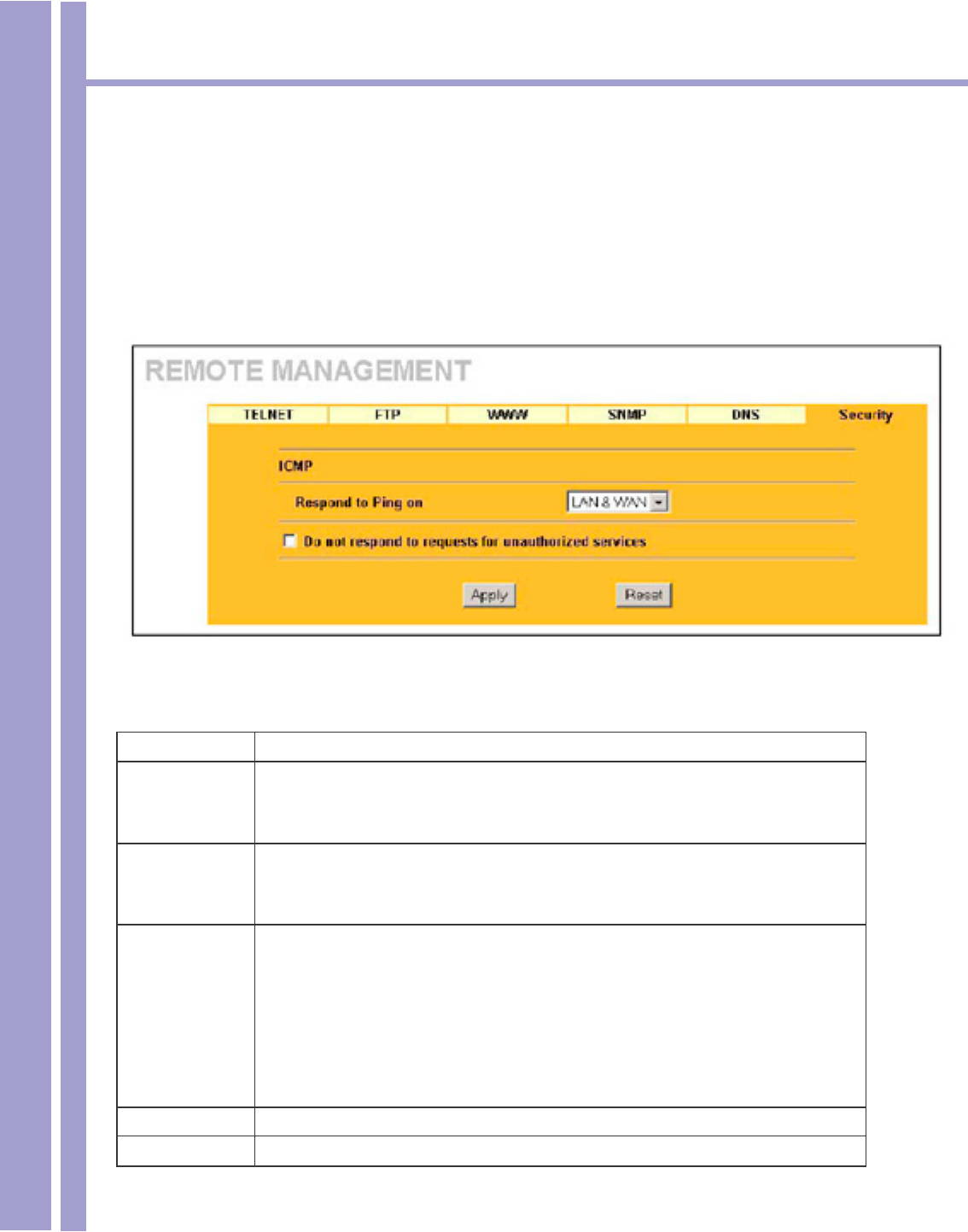
To change your 1500WR Wireless Router’s security settings, click ADVANCED, REMOTE MANAGE-
MENT and then the Security tab. The screen appears as shown.
If an outside user attempts to probe an unsupported port on your 1500WR Wireless Router, an ICMP
response packet is automatically returned. This allows the outside user to know the 1500WR Wireless
Router exists. The 1500WR Wireless Router series support anti-probing, which prevents the ICMP
response packet from being sent. This keeps outsiders from discovering your 1500WR Wireless Router
when unsupported ports are probed.
The following table describes the labels in this screen.
Security
LABEL DESCRIPTION
ICMP Internet Control Message Protocol is a message control and error-reporting protocol
between a host server and a gateway to the Internet. ICMP uses Internet Protocol
(IP) datagrams, but the messages are processed by the TCP/IP software and directly
apparent to the application user.
Respond to Ping
on
The 1500WR Wireless Router will not respond to any incoming Ping requests when
Disable is selected. Select LAN to reply to incoming LAN Ping requests. Select WAN
to reply to incoming WAN Ping requests. Otherwise select LAN&WAN to reply to both
incoming LAN and WAN Ping requests.
Do not respond
to requests for
unauthorized
services
Select this option to prevent hackers from nding the 1500WR Wireless Router by
probing for unused ports. If you select this option, the 1500WR Wireless Router will
not send ICMP response packets to port request(s) for unused ports, thus leaving the
unused ports and the 1500WR Wireless Router unseen.
If the rewall blocks a packet from the WAN, the 1500WR Wireless Router sends
a TCP reset packet. Use the “sys rewall tcprst rst off’ command in the command
interpreter if you want to stop the 1500WR Wireless Router from sending TCP reset
packets.
Apply Click Apply to save your changes back to the 1500WR Wireless Router.
Reset Click Reset to begin conguring this screen afresh.

Horizons 1500WR Wireless 4-Port Router
108
ParkerVision

Horizons 1500WR Wireless 4-Port Router
109
ParkerVision
This part provides information and conguration instructions for UPnP
(Universal Plug and Play) and the logs.
Part VI
UPnP and LOGS

Horizons 1500WR Wireless 4-Port Router
110
ParkerVision
Chapter 14
UPnP Screen
This chapter introduces the Universal Plug and Play feature of the 1500WR
14.1 Universal Plug and Play Overview
Universal Plug and Play (UPnP) is a distributed, open networking standard that uses TCP/IP for
simple peer-to-peer network connectivity between devices. A UPnP device can dynamically join a
network, obtain an IP address, convey its capabilities and learn about other devices on the network.
In turn, a device can leave a network smoothly and automatically when it is no longer in use.
14.1.1 How Do I Know If I’m Using UPnP?
UPnP hardware is identied as an icon in the Network Connections folder (Windows XP). Each UPnP
compatible device installed on your network will appear as a separate icon. Selecting the icon of a
UPnP device will allow you to access the information and properties of that device.
14.1.2 NAT Traversal
UPnP NAT traversal automates the process of allowing an application to operate through NAT. UPnP
network devices can automatically congure network addressing, announce their presence in the
network to other UPnP devices and enable exchange of simple product and service descriptions.
NAT traversal allows the following:
• Dynamic port mapping
• Learning public IP addresses
• Assigning lease times to mappings
Windows Messenger is an example of an application that supports NAT traversal and UPnP. See the
SUA/NAT chapter for further information about NAT.
14.2 Cautions with UPnP
The automated nature of NAT traversal applications in establishing their own services and opening
rewall ports may present network security issues. Network information and conguration may also
be obtained and modied by users in some network environments.
All UPnP-enabled devices may communicate freely with each other without additional conguration.
Disable UPnP if this is not your intention.
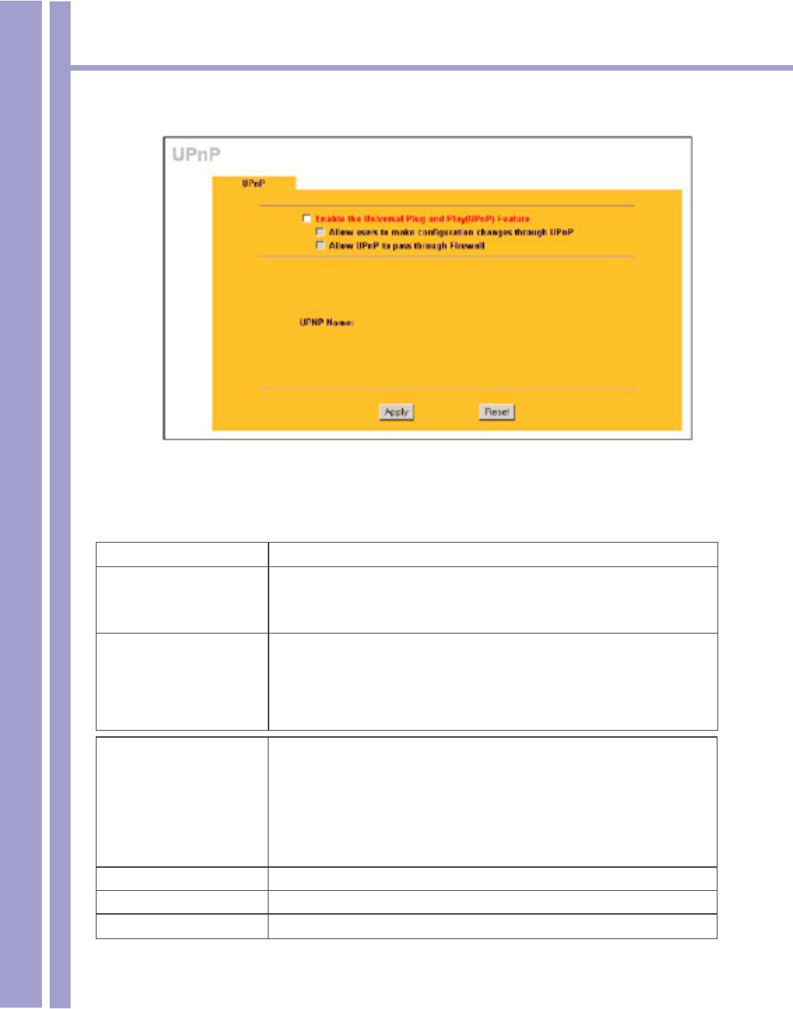
14.3 Conguring UPnP
Click ADVANCED and then UPnP to display the screen shown on the next page.
Horizons 1500WR Wireless 4-Port Router
111
ParkerVision
14.3 Conguring UPnP - Continued
The following table describes the labels in this screen.
Conguring UPnP
LABEL DESCRIPTION
Enable the Universal Plug
and Play (UPnP) feature
Select this check box to activate UPnP. Be aware that anyone could use a
UPnP application to open the web Web Conguration Utility’s login screen
without entering the 1500WR Wireless Router’s IP address (although you must
still enter the password to access the web Web Conguration Utility).
Allow users to make
conguration changes
through UPnP
Select this check box to allow UPnP-enabled applications to automatically
congure the 1500WR Wireless Router so that they can communicate
through the 1500WR Wireless Router, for example by using NAT traversal,
UPnP applications automatically reserve a NAT forwarding port in order to
communicate with another UPnP enabled device; this eliminates the need to
manually congure port forwarding for the UPnP enabled application.
Allow UPnP to pass
through Firewall
Select this check box to create a static LAN to LAN/1500WR Wireless Router
rule that allows forwarding of ports 1900 and 80. Selecting this check box also
creates a dynamic rewall rule every time a NAT forwarding port is reserved
for UPnP. This setting remains active until you disable UPnP or clear this
check box.
Clear this check box to have the rewall block all UPnP application packets
(for example, MSN packets) instead of creating a rewall rule for them.
UPnP Name This identies the 1500WR Wireless Router in UPnP applications.
Apply Click Apply to save your changes back to the 1500WR Wireless Router.
Reset Click Reset to begin conguring this screen afresh.
Horizons 1500WR Wireless 4-Port Router
112
ParkerVision
14.4 Installing UPnP in Windows Example
This section shows how to install UPnP in Windows XP
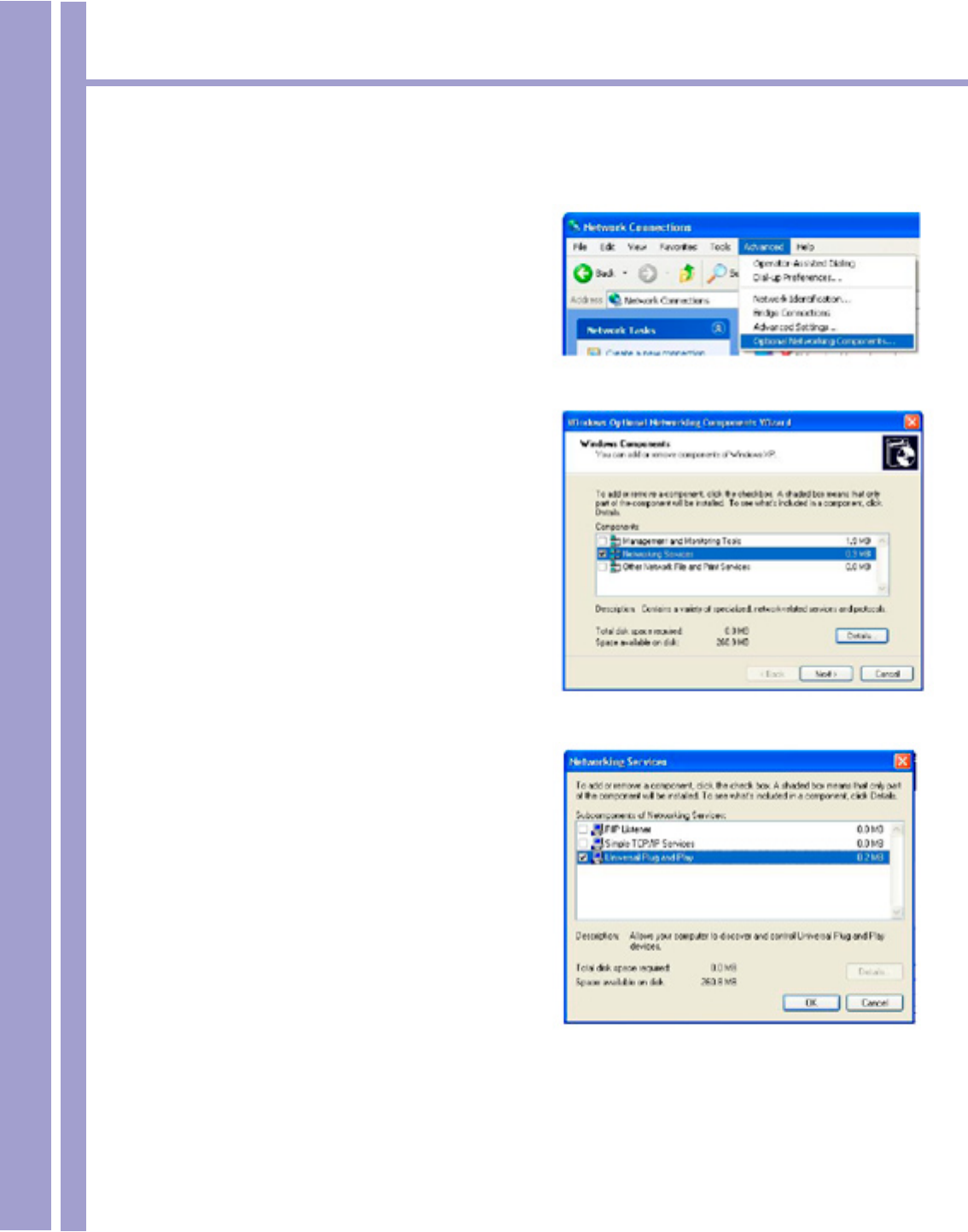
14.4.2 Installing UPnP in Windows XP
Follow the steps below to install UPnP in Windows
XP.
Step 1. Click Start and Control Panel.
Step 2. Double-click Network Connections.
Step 3. In the Network Connections window,
click Advanced in the main menu and
select Optional Networking
Components ....
The Windows Optional Networking
Components Wizard window displays.
Step 4. Select Networking Service in the
Components selection box and click
Details.
Step 5. In the Networking Services window,
select the Universal Plug and Play
check box.
Step 6. Click OK to go back to the Windows
Optional Networking Component
Wizard window and click Next.
Horizons 1500WR Wireless 4-Port Router
113
ParkerVision
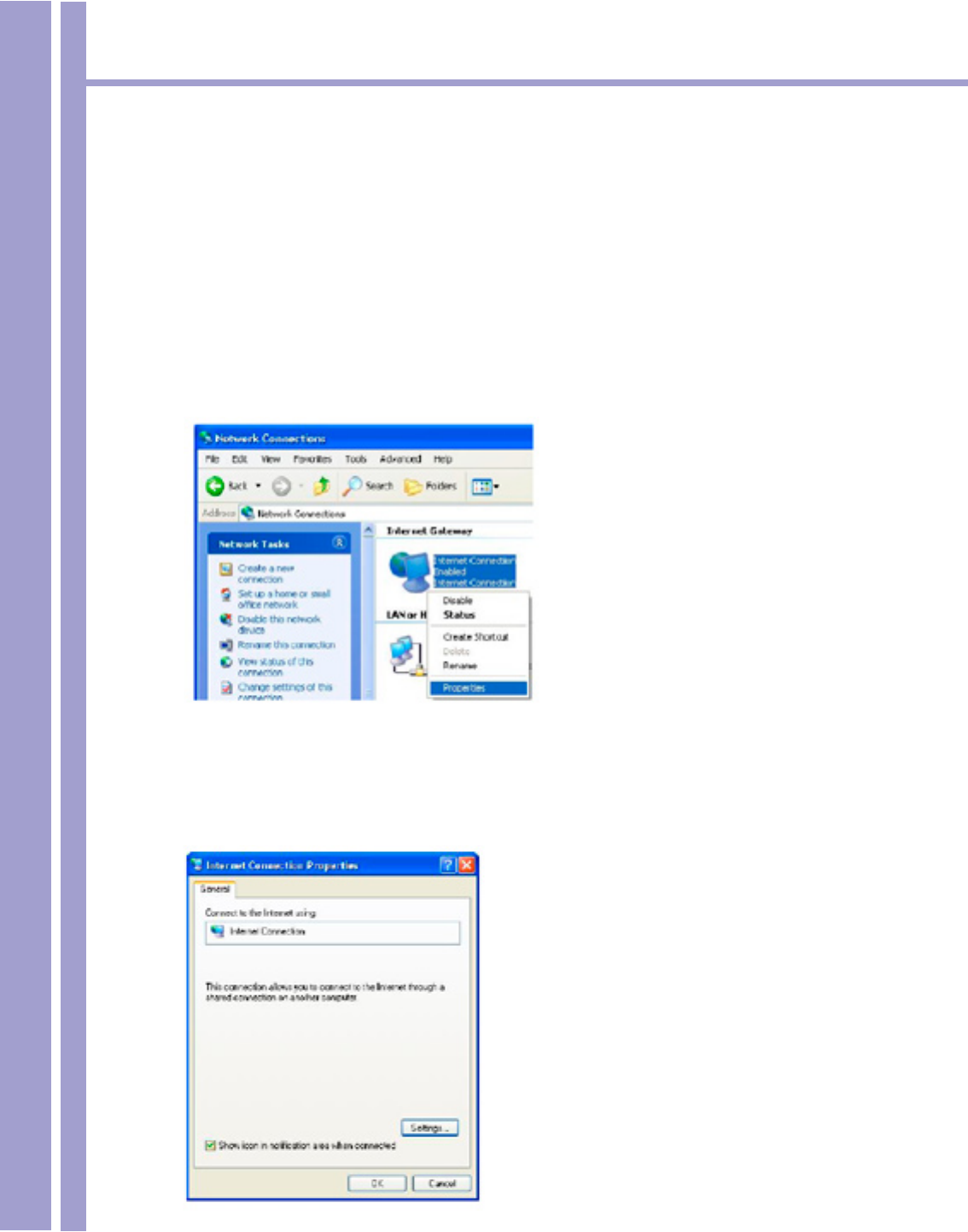
14.5 Using UPnP in Windows XP Example
This section shows you how to use the UPnP feature in Windows XP. You must already have UPnP
installed in Windows XP and UPnP activated on the 1500WR Wireless Router.
Make sure the computer is connected to a LAN port of the 1500WR Wireless Router. Turn on your
computer and the 1500WR Wireless Router.
14.5.1 Auto-discover Your UPnP-enabled Network Device
Step 1. Click Start and Control Panel. Double-
click Network Connections. An icon displays
under Internet Gateway.
Step 2. Right-click the icon and select Properties.
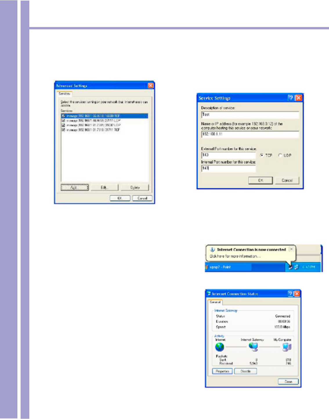
Step 3. In the Internet Connection Properties
window, click Settings to see the port
mappings that were automatically created.
Continued next page
Horizons 1500WR Wireless 4-Port Router
114
ParkerVision
14.5.1 Auto-discover Your UPnP-enabled Network Device - Continued
Step 4. You may edit or delete the port mappings or click Add to manually add port mappings.
When the UPnP-enabled device is disconnected from your computer,
all port mappings will be deleted automatically.
Step 5. Select the Show icon in notication area
Step 6. Double-click the icon to display your current
Internet connection status.
Horizons 1500WR Wireless 4-Port Router
115
ParkerVision
14.5.2 Web Web Conguration Utility Easy Access
With UPnP, you can access the web-based Web Conguration Utility on the 1500WR Wireless Router
without nding out the IP address of the 1500WR Wireless Router rst. This is helpful if you do not
know the IP address of the 1500WR Wireless Router.
Follow the steps below to access the web Web Conguration Utility.
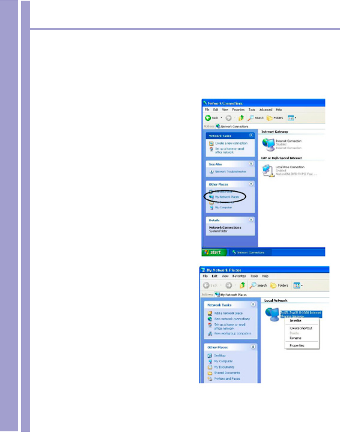
Step 1. Click start and then Control Panel.
Step 2. Double-click Network Connections.
Step 3. Select My Network Places under Other
Places.
Step 4. An icon with the description for each
UPnP-enabled device displays under
Local Network.
Step 5. Right-click the icon for your 1500WR
Wireless Router and select Invoke.
The web Web Conguration Utility
login screen displays.
Step 6. Right-click the icon for your 1500WR
Wireless Router and select Properties.
A properties window displays with basic
information about the 1500WR Wireless
Router. (Screen not shown)
Horizons 1500WR Wireless 4-Port Router
116
ParkerVision
Chapter 15
Logs Screens
This chapter contains information about conguring general log settings and viewing the 1500WR
Wireless Router’s logs. Refer to the appendix for example log message explanations.
15.1 Using the View Log Screen
The web Web Conguration Utility allows you to look at all of the 1500WR Wireless Router’s logs in
one location.
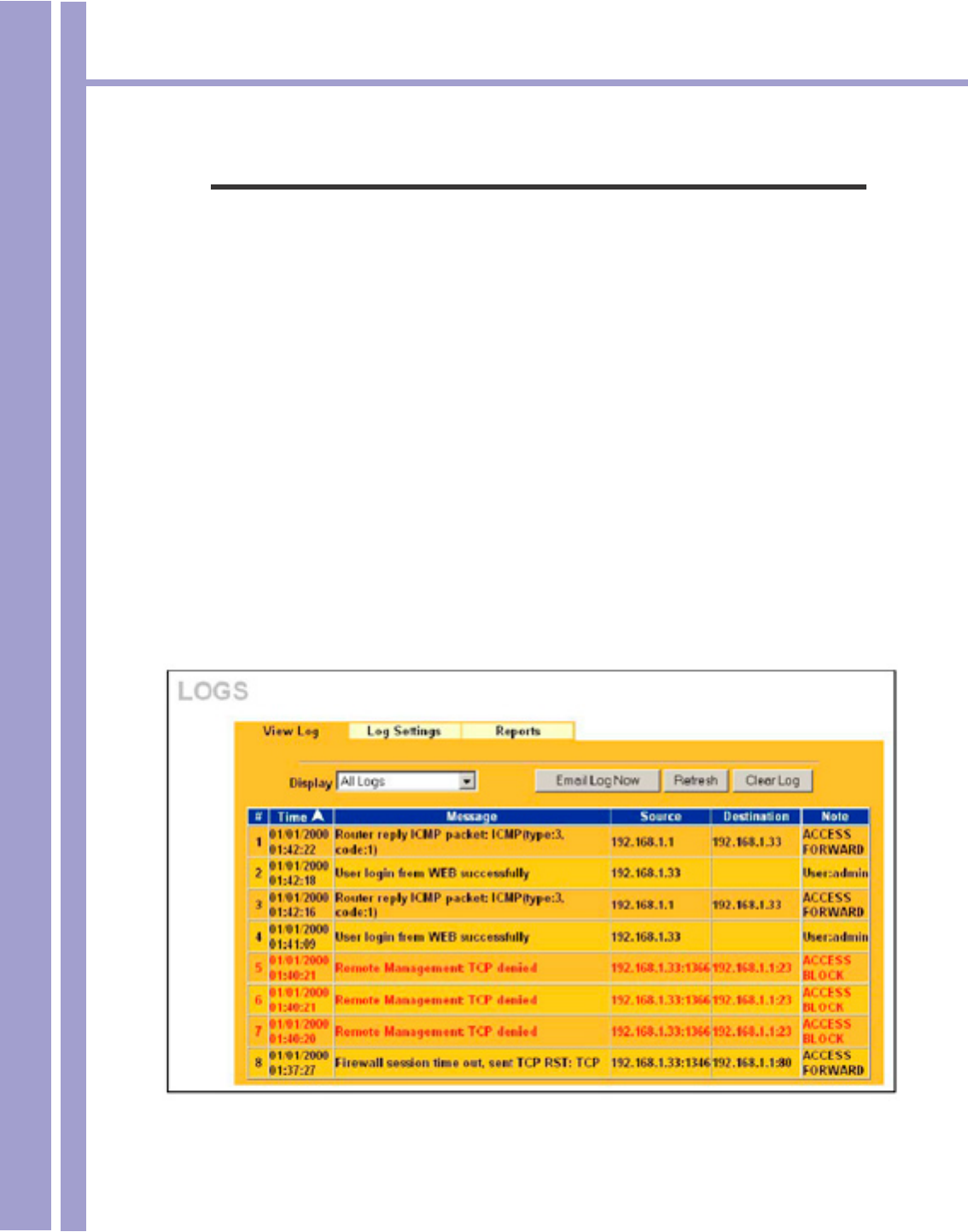
Click ADVANCED and then LOGS to open the View Log screen. Use the View Log screen to see
the logs for the categories that you selected in the Log Settings screen (see section 15.2). Options
include logs about system maintenance, system errors, access control, allowed or blocked web sites,
blocked web features (such as ActiveX controls, Java and cookies), attacks (such as DoS) and IP-
Sec.
You can view logs and alert messages in this page. Log entries in red indicate system error logs.
Once the log entries are all used, the log will wrap around and the old logs will be deleted.
Click a column heading to sort the entries. A triangle indicates the direction of the sort order.
The table on the following page describes the labels in the screen above.

Horizons 1500WR Wireless 4-Port Router
117
ParkerVision
15.1 Using the View Log Screen - Continued
The following table describes the labels in the screen on the proceeding page.
View Log
LABEL DESCRIPTION
Display Select a log category from the drop down list box to display logs within the selected
category. To view all logs, select All Logs. The number of categories shown in the drop
down list box depends on the selection in the Log Settings page.
Time This eld displays the time the log was recorded.
Message This eld states the reason for the log.
Source This eld lists the source IP address and the port number of the incoming packet.
Destination This eld lists the destination IP address and the port number of the incoming packet.
Notes This eld displays additional information about the log entry.
Email Log Now Click Email Log Now to send the log screen to the e-mail address specied in the
Log Settings page.
Refresh Click Refresh to renew the log screen.
Clear Log Click Clear Log to clear all the logs.
15.2 Conguring Log Settings
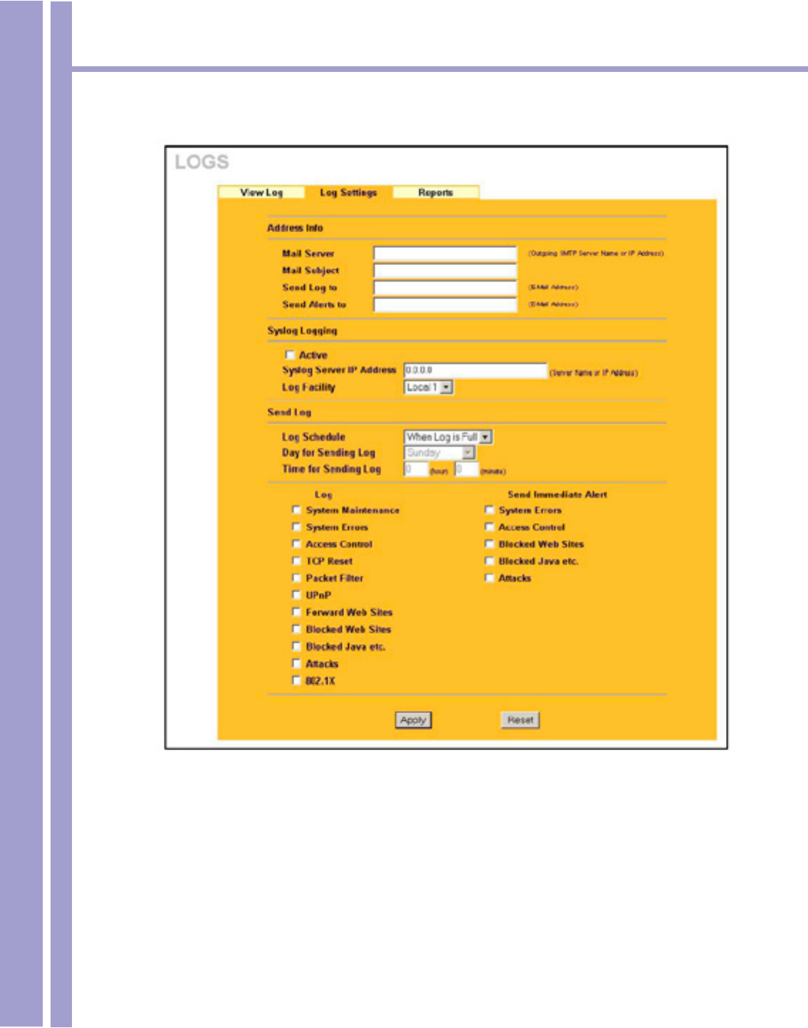
To change your 1500WR Wireless Router’s log settings, click ADVANCED, LOGS and then the Log
Settings tab. The screen appears as shown.
Use the Log Settings screen to congure to where the 1500WR Wireless Router is to send the logs; the
schedule for when the 1500WR Wireless Router is to send the logs and which logs and/or immediate
alerts the 1500WR Wireless Router is to send.
An alert is a type of log that warrants more serious attention. They include system errors, attacks (ac-
cess control) and attempted access to blocked web sites or web sites with restricted web features such
as cookies, Active X and so on. Some categories such as System Errors consist of both logs and alerts.
You may differentiate them by their color in the View Log screen.
Alerts are displayed in red and logs are displayed in black.
Horizons 1500WR Wireless 4-Port Router
118
ParkerVision
15.2 Conguring Log Settings - Continued
The table on the following page describes the labels in the screen above.

Horizons 1500WR Wireless 4-Port Router
119
ParkerVision
15.2 Conguring Log Settings - Continued
The following table describes the labels in the screen on the proceeding page.
Log Settings
LABEL DESCRIPTION
Address Info
Mail Server Enter the server name or the IP address of the mail server for the e-mail
addresses specied below. If this eld is left blank, logs and alert messages will
not be sent via e-mail.
Mail Subject Type a title that you want to be in the subject line of the log e-mail message that
the 1500WR Wireless Router sends.
Send Log to Logs are sent to the e-mail address specied in this eld. If this eld is left blank,
logs will not be sent via e-mail.
Send Alerts to Enter the e-mail address where the alert messages will be sent. Alerts include
system errors, attacks and attempted access to blocked web sites. If this eld is
left blank, alert messages will not be sent via e-mail.
Syslog Logging UNIX syslog sends a log to an external UNIX server used to store logs.
Active Click Active to enable UNIX syslog.
Syslog Server IP
Address
Enter the server name or the IP address of the syslog server that will log the CDR
(Call Detail Record) and system messages.
Log Facility Select the Local from the drop down list box. The log facility allows you to log the
messages to different les in the syslog server. Refer to your UNIX manual for
more information.
Send Log
Log Schedule This drop-down menu is used to congure the frequency of log messages being sent
as E-mail:
• Daily • Weekly • Hourly • When the Log is Full • None.
If the Weekly or the Daily option is selected, specify a time of day when the E-mail
should be sent. If the Weekly option is selected, then also specify which day of the
week the E-mail should be sent. If the When Log is Full option is selected, an alert
is sent when the log lls up. If you select None, no log messages are sent.
Day for Sending Log This eld is only available when you select Weekly in the Log Schedule eld.
Use the drop down list box to select which day of the week to send the logs.
Time for Sending Log Enter the time of the day in 24-hour format (for example 23:00 equals 11:00 pm) to
send the logs.
Log Select the categories of logs that you want to record.
Send Immediate Alert Select the categories of alerts for which you want the 1500WR Wireless Router to
immediately send e-mail alerts.
Apply Click Apply to save your changes back to the 1500WR Wireless Router.
Reset Click Reset to begin conguring this screen afresh.
Horizons 1500WR Wireless 4-Port Router
120
ParkerVision
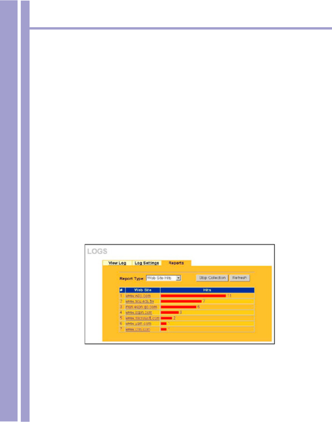
15.3 Conguring Reports
To change your 1500WR Wireless Router’s log reports, click ADVANCED, LOGS and then the
Reports tab. The screen appears as shown.
The Reports screen displays which computers on the LAN send and receive the most trafc, what kinds
of trafc are used the most and which web sites are visited the most often. Use the Reports screen to
view information about bandwidth usage :
> Web sites visited the most often
> Number of times the most visited web sites were visited
> The most-used protocols or service ports
> The amount of trafc for the most used protocols or service ports
> The LAN IP addresses to and/or from which the most trafc has been sent
> How much trafc has been sent to and from the LAN IP addresses to and/or from which the
most trafc has been sent
The web site hit count may not be 100% accurate because sometimes when an individual web
page loads, it may contain references to other web sites that also get counted as hits.
The 1500WR Wireless Router records web site hits by counting the HTTP GET packets. Many web
sites include HTTP GET references to other web sites and the 1500WR Wireless Router may count
these as hits, thus the web hit count is not (yet) 100% accurate.
Enabling the 1500WR Wireless Router’s reporting function decreases the
overall throughput by about 1 Mbps.
The table on the following page describes the labels in the screen above.

Horizons 1500WR Wireless 4-Port Router
121
ParkerVision
15.3 Conguring Reports - Continued
The following table describes the labels in the screen on the proceeding page.
Reports
LABEL DESCRIPTION
Report Type Use the drop-down list box to select the type of reports to display.
Web Site Hits displays the web sites that have been visited the most often from the LAN
and how many times they have been visited.
Protocol/Port displays the protocols or service ports that have been used the most and
the amount of trafc for the most used protocols or service ports.
LAN IP Address displays the LAN IP addresses to and /or from which the most trafc
has been sent and how much trafc has been sent to and from those IP addresses.
Start Collection/
Stop Collection
The button text shows Start Collection when the 1500WR Wireless Router is not
recording report data and Stop Collection when the 1500WR Wireless Router is
recording report data.
Click Start Collection to have the 1500WR Wireless Router record report data. Click
Stop Collection to halt the 1500WR Wireless Router from recording more data.
Refresh Click Refresh to update the report display. The report also refreshes automatically
when you close and reopen the screen.
# This eld displays the index number of an individual web site.
Web Site Web Site displays the web site address(es) that have been visited the most often
from the LAN.
Hits Hits displays the total number of visits to each web site.
Horizons 1500WR Wireless 4-Port Router
122
ParkerVision
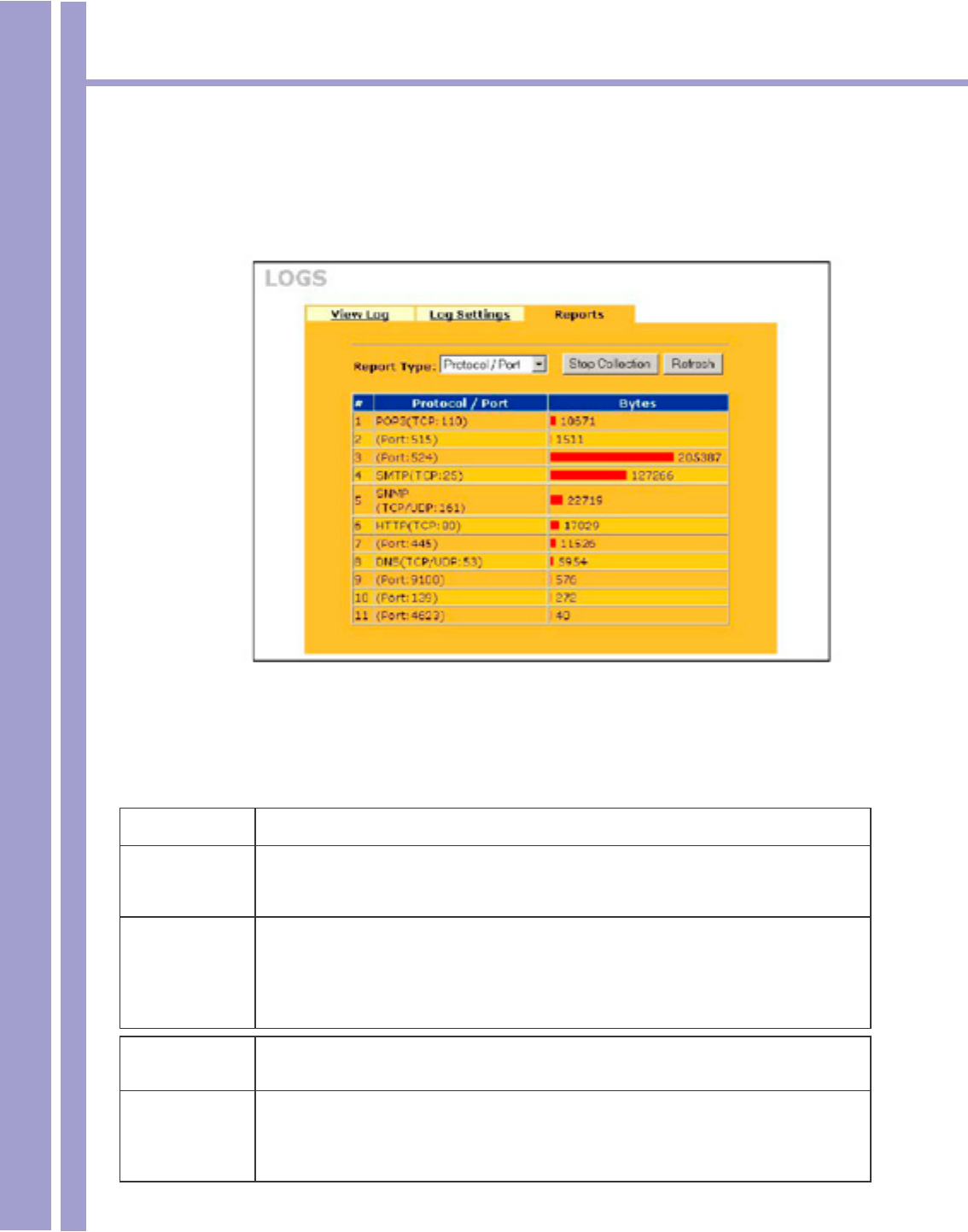
15.3.1 Viewing Protocol/Port
In the Reports screen, select Protocol/Port from the Report Type drop-down list box to have the
1500WR Wireless Router record and display which protocols or service ports have been used the most
and the amount of trafc for the most used protocols or service ports.
The following table describes the labels in this screen.
Protocol/Port Report
LABEL DESCRIPTION
Protocol/Port This column lists the protocols or service ports for which the most trafc has gone
through the 1500WR Wireless Router. The protocols or service ports are listed in
descending order with the most used protocol or service port listed rst.
Start Collection/
Stop Collection
The button text shows Start Collection when the 1500WR Wireless Router is not
recording report data and Stop Collection when the 1500WR Wireless Router is
recording report data.
Click Start Collection to have the 1500WR Wireless Router record report data. Click
Stop Collection to halt the 1500WR Wireless Router from recording more data.
Refresh Click Refresh to update the report display. The report also refreshes automatically when
you close and reopen the screen.
Bytes This column lists how much trafc has been sent and/or received for each protocol or
service port. The measurement unit shown (bytes, Kbytes, Mbytes or Gbytes) varies with
the amount of trafc for the particular protocol or service port. The count starts over at 0 if
a protocol or port passes the bytes count limit (see Table 15-6).
Horizons 1500WR Wireless 4-Port Router
123
ParkerVision
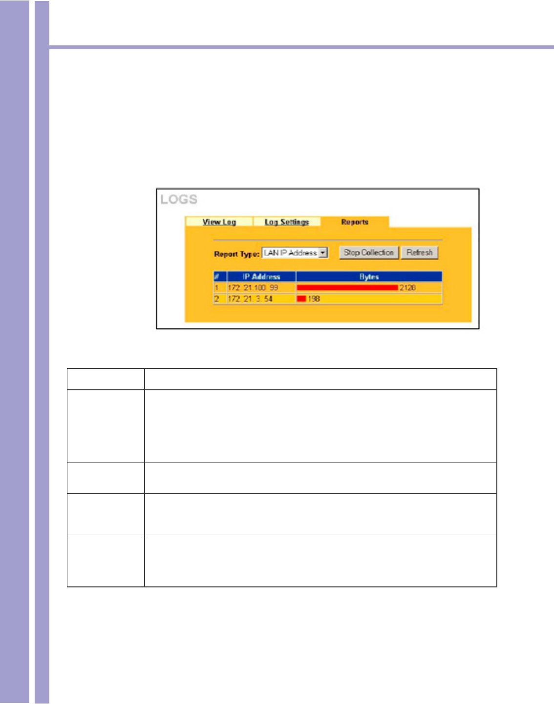
15.3.2 Viewing LAN IP Address
In the Reports screen, select LAN IP Address from the Report Type drop-down list box to have the
1500WR Wireless Router record and display the LAN IP addresses that the most trafc has been sent
to and/or from and how much trafc has been sent to and/or from those IP addresses.
Computers take turns using dynamically assigned LAN IP addresses.
The 1500WR Wireless Router continues recording the bytes sent to or from a LAN IP
address when it is assigned to a different computer.
LAN IP Address Report
LABEL DESCRIPTION
Start Collection/
Stop Collection
The button text shows Start Collection when the 1500WR Wireless Router is not
recording report data and Stop Collection when the 1500WR Wireless Router is
recording report data.
Click Start Collection to have the 1500WR Wireless Router record report data. Click
Stop Collection to halt the 1500WR Wireless Router from recording more data.
Refresh Click Refresh to update the report display. The report also refreshes automatically when
you close and reopen the screen.
IP Address This column lists the LAN IP addresses to and/or from which the most trafc has been
sent. The LAN IP addresses are listed in descending order with the LAN IP address to
and/or from which the most trafc was sent listed rst.
Bytes This column displays how much trafc has gone to and from the listed LAN IP
addresses. The measurement unit shown (bytes, Kbytes, Mbytes or Gbytes) varies with
the amount of trafc sent to and from the LAN IP address. The count starts over at 0 if
the total trafc sent to and from a LAN IP passes the bytes count limit (see Table 15-6).

Horizons 1500WR Wireless 4-Port Router
124
ParkerVision
15.3.3 Reports Specications
The following table lists detailed specications on the reports feature.
Report Specications
LABEL DESCRIPTION
Number of web
sites/protocols
or ports/IP
addresses listed:
20
Hit count limit: Up to 232 hits can be counted per web site. The count starts over at 0 if it passes four
billion.
Bytes count
limit:
Up to 264 bytes can be counted per protocol/port or LAN IP address. The count starts
over at 0 if it passes 264 bytes.

Horizons 1500WR Wireless 4-Port Router
125
ParkerVision
This part describes the Maintenance web Web Conguration Utility screens.
Part VII
Maintenance
Horizons 1500WR Wireless 4-Port Router
126
ParkerVision
Chapter 16
Maintenance
This chapter displays system information such as rmware, port IP addresses and port trafc statistics.
16.1 Maintenance Overview
The maintenance screens can help you view system information, upload new rmware, manage
conguration and restart your 1500WR Wireless Router.
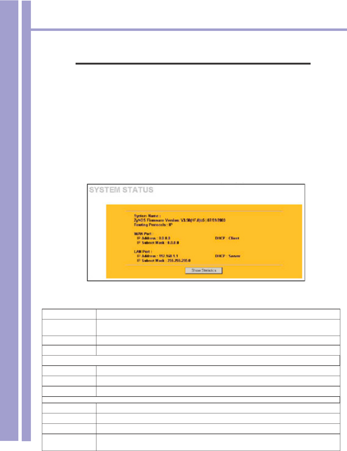
16.2 System Status Screen
Click MAINTENANCE to open the System Status screen, where you can use to monitor your
1500WR Wireless Router. Note that these elds are READ-ONLY and are meant to be used for
diagnostic purposes.
The following table describes the information in the SYSTEM STATUS screen:
LABEL DESCRIPTION
System Name This is the System Name you enter in the rst Internet Access Wizard screen. It is for
identication purposes.
Firmware Version This is the rmware version and the date created.
Routing Protocols This shows the routing protocol - IP for which the 1500WR Wireless Router is congured.
WAN Port
IP Address This is the WAN port IP address.
IP Subnet Mask This is the WAN port subnet mask.
DHCP This is the WAN port DHCP role - Client or None.
LAN Port
IP Address This is the LAN port IP address.
IP Subnet Mask This is the LAN port subnet mask.
DHCP This is the LAN port DHCP role - Server, Client or None.
Show Statistics Click Show Statistics to see router performance statistics such as number of packets sent
and number of packets received for each port.
Horizons 1500WR Wireless 4-Port Router
127
ParkerVision
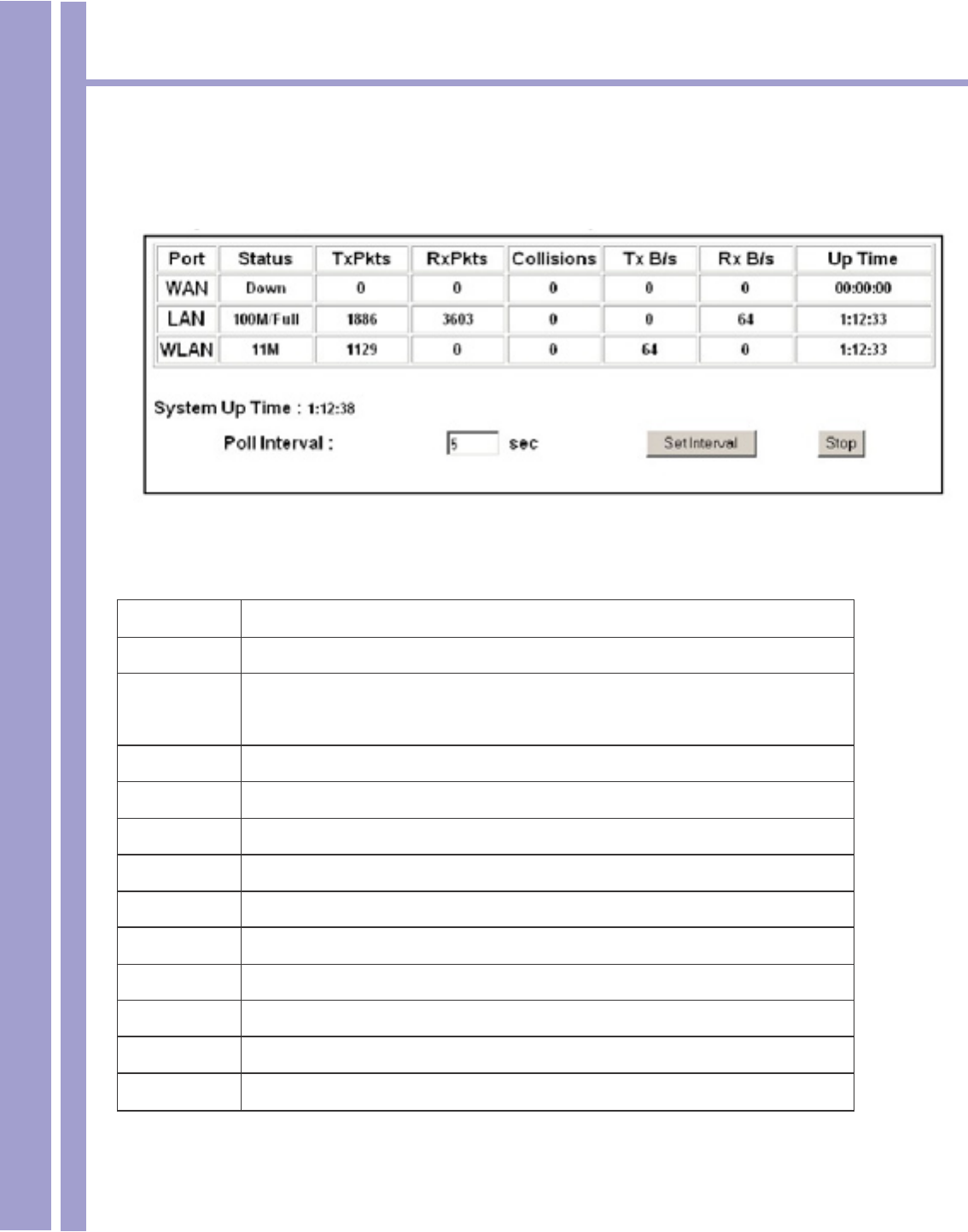
16.2.1 System Statistics
Read-only information here includes port status and packet specic statistics. Also provided are
“system up time” and “poll interval(s)”. The Poll Interval eld is congurable.
The following table describes the labels in this screen.
System Status: Show Statistics
LABEL DESCRIPTION
Port This is the LAN or WAN port.
Status This shows the port speed and duplex setting if you are using Ethernet encapsulation for
the Ethernet port. This shows the transmission speed only for wireless port.
TxPkts This is the number of transmitted packets on this port.
RxPkts This is the number of received packets on this port.
Collisions This is the number of collisions on this port.
TxB/s This shows the transmission speed in bytes per second on this port.
RxB/s This shows the reception speed in bytes per second on this port.
Up Time This is the total amount of time the line has been up.
System Up Time This is the total time the 1500WR Wireless Router has been on.
Poll Interval Enter the time interval for refreshing statistics.
Set Interval Click this button to apply the new poll interval you entered above.
Stop Click this button to stop refreshing statistics.
Horizons 1500WR Wireless 4-Port Router
128
ParkerVision
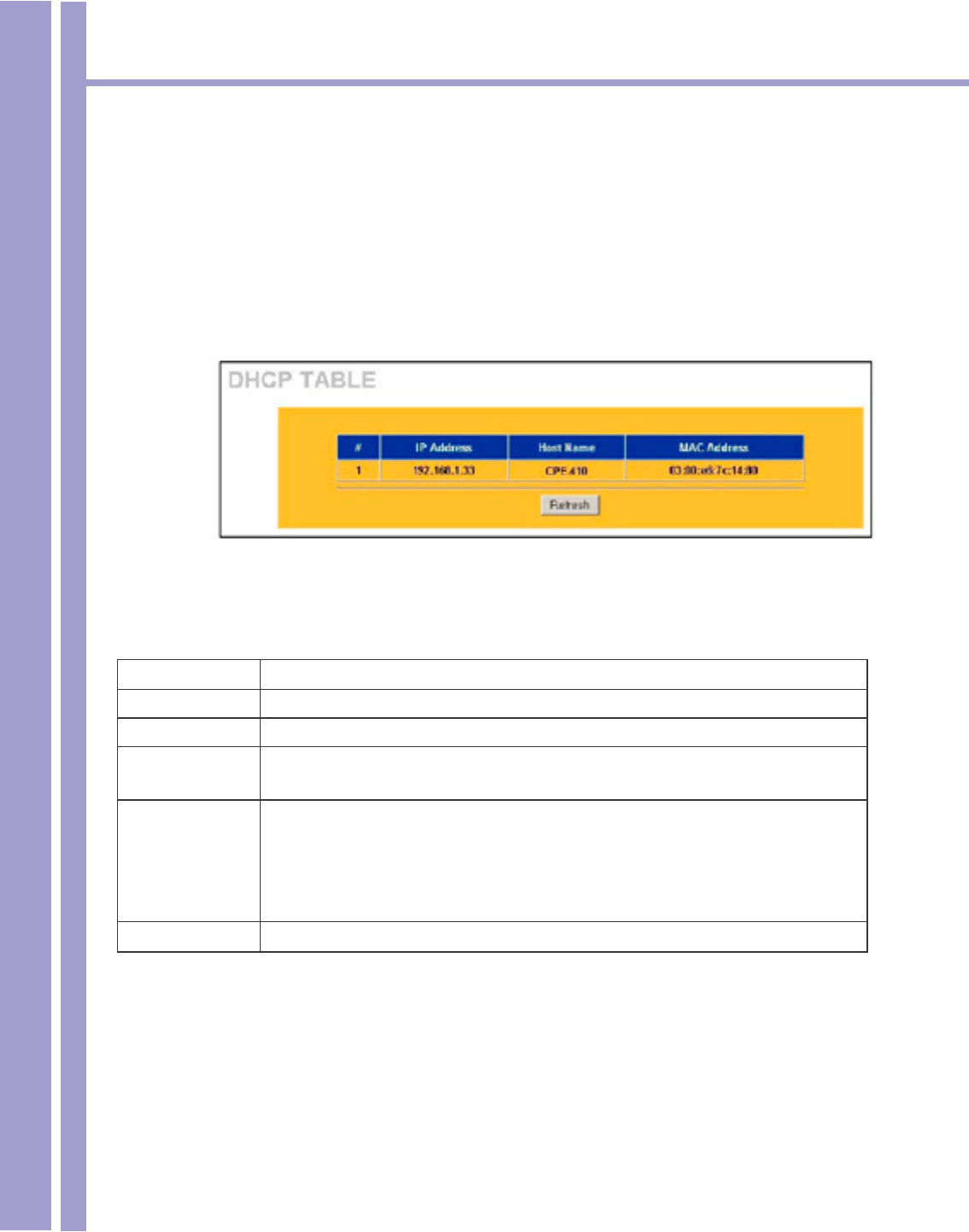
16.3 DHCP Table Screen
DHCP (Dynamic Host Conguration Protocol, RFC 2131 and RFC 2132) allows individual clients to ob-
tain TCP/IP conguration at start-up from a server. You can congure the 1500WR Wireless Router as
a DHCP server or disable it. When congured as a server, the 1500WR Wireless Router provides the
TCP/IP conguration for the clients. If set to None, DHCP service will be disabled and you must have
another DHCP server on your LAN, or else the computer must be manually congured.
Click MAINTENANCE and then DHCP TABLE. Read-only information here relates to your DHCP
status. The DHCP table shows current DHCP client information (including IP Address, Host Name and
MAC Address) of all network clients using the DHCP server.
The following table describes the labels in this screen.
DHCP Table
LABEL DESCRIPTION
# This is the index number of an associated wireless station.
IP Address This eld displays the IP Address relative to the # eld listed above.
Host Name This eld displays the computer host name.
MAC Address The MAC (Media Access Control) or Ethernet address on a LAN (Local Area Network) is
unique to your computer (six pairs of hexadecimal notation).
A network interface card, such as an Ethernet adapter, has a hardwired address that is
assigned at the factory. This address follows an industry standard that ensures no other
adapter has a similar address.
Refresh Click Refresh to reload the DHDCP table.
Horizons 1500WR Wireless 4-Port Router
129
ParkerVision
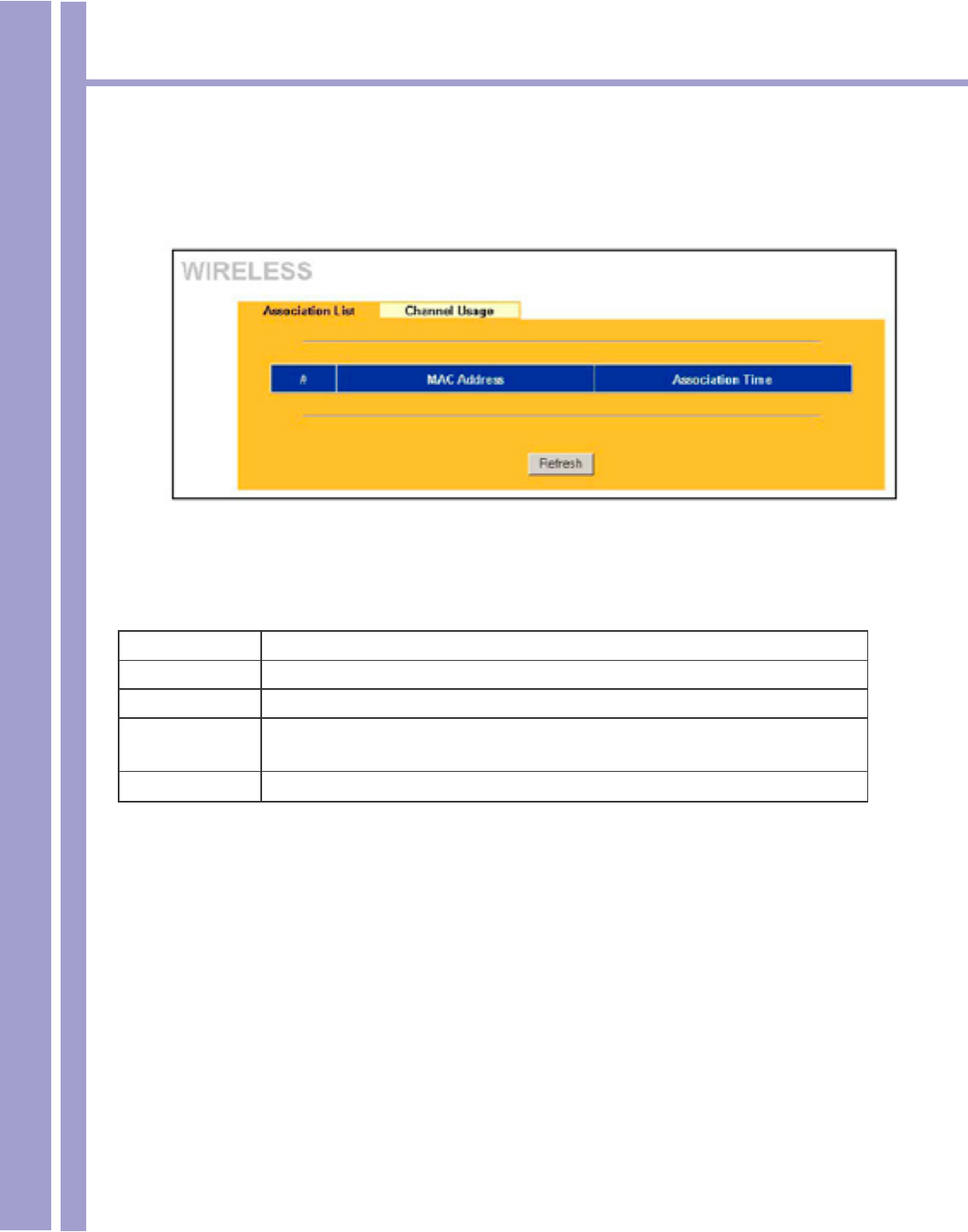
16.4 Wireless Screen
View the wireless stations that are currently associated to the 1500WR in the Association List
Screen. Click Maintenance, and then Wireless to bring up the screen shown below.
The following table describes the labels in this screen.
Association List
LABEL DESCRIPTION
# This is the index number of an associated wireless station.
MAC Address This eld displays the MAC address of an associated wireless station.
Association Time This eld displays the time a wireless station rst associated with the 1500WR Wireless
Router.
Refresh Click Refresh to reload the screen.

Horizons 1500WR Wireless 4-Port Router
130
ParkerVision

Horizons 1500WR Wireless 4-Port Router
131
ParkerVision

Horizons 1500WR Wireless 4-Port Router
132
ParkerVision

Horizons 1500WR Wireless 4-Port Router
133
ParkerVision

Horizons 1500WR Wireless 4-Port Router
134
ParkerVision

Horizons 1500WR Wireless 4-Port Router
135
ParkerVision

Horizons 1500WR Wireless 4-Port Router
136
ParkerVision

Horizons 1500WR Wireless 4-Port Router
137
ParkerVision

Horizons 1500WR Wireless 4-Port Router
138
ParkerVision

Horizons 1500WR Wireless 4-Port Router
139
ParkerVision

Horizons 1500WR Wireless 4-Port Router
140
ParkerVision

Horizons 1500WR Wireless 4-Port Router
141
ParkerVision

Horizons 1500WR Wireless 4-Port Router
142
ParkerVision

Horizons 1500WR Wireless 4-Port Router
143
ParkerVision

Horizons 1500WR Wireless 4-Port Router
144
ParkerVision

Horizons 1500WR Wireless 4-Port Router
145
ParkerVision

Horizons 1500WR Wireless 4-Port Router
146
ParkerVision

Horizons 1500WR Wireless 4-Port Router
147
ParkerVision

Horizons 1500WR Wireless 4-Port Router
148
ParkerVision

Horizons 1500WR Wireless 4-Port Router
149
ParkerVision

Horizons 1500WR Wireless 4-Port Router
150
ParkerVision

Horizons 1500WR Wireless 4-Port Router
151
ParkerVision

Horizons 1500WR Wireless 4-Port Router
152
ParkerVision

Horizons 1500WR Wireless 4-Port Router
153
ParkerVision

Horizons 1500WR Wireless 4-Port Router
154
ParkerVision

Horizons 1500WR Wireless 4-Port Router
155
ParkerVision

Horizons 1500WR Wireless 4-Port Router
156
ParkerVision

Horizons 1500WR Wireless 4-Port Router
157
ParkerVision

Horizons 1500WR Wireless 4-Port Router
158
ParkerVision

Horizons 1500WR Wireless 4-Port Router
159
ParkerVision

Horizons 1500WR Wireless 4-Port Router
160
ParkerVision

Horizons 1500WR Wireless 4-Port Router
161
ParkerVision

Horizons 1500WR Wireless 4-Port Router
162
ParkerVision

Horizons 1500WR Wireless 4-Port Router
163
ParkerVision

Horizons 1500WR Wireless 4-Port Router
164
ParkerVision

Horizons 1500WR Wireless 4-Port Router
165
ParkerVision

Horizons 1500WR Wireless 4-Port Router
166
ParkerVision

Horizons 1500WR Wireless 4-Port Router
167
ParkerVision

Horizons 1500WR Wireless 4-Port Router
168
ParkerVision

Horizons 1500WR Wireless 4-Port Router
169
ParkerVision

Horizons 1500WR Wireless 4-Port Router
170
ParkerVision

Horizons 1500WR Wireless 4-Port Router
171
ParkerVision

Horizons 1500WR Wireless 4-Port Router
172
ParkerVision

Horizons 1500WR Wireless 4-Port Router
173
ParkerVision

Horizons 1500WR Wireless 4-Port Router
174
ParkerVision

Horizons 1500WR Wireless 4-Port Router
175
ParkerVision

Horizons 1500WR Wireless 4-Port Router
176
ParkerVision

Horizons 1500WR Wireless 4-Port Router
177
ParkerVision

Horizons 1500WR Wireless 4-Port Router
178
ParkerVision

Horizons 1500WR Wireless 4-Port Router
179
ParkerVision

Horizons 1500WR Wireless 4-Port Router
180
ParkerVision

Horizons 1500WR Wireless 4-Port Router
181
ParkerVision

Horizons 1500WR Wireless 4-Port Router
182
ParkerVision

Horizons 1500WR Wireless 4-Port Router
183
ParkerVision

Horizons 1500WR Wireless 4-Port Router
184
ParkerVision

Horizons 1500WR Wireless 4-Port Router
185
ParkerVision

Horizons 1500WR Wireless 4-Port Router
186
ParkerVision

Horizons 1500WR Wireless 4-Port Router
187
ParkerVision

Horizons 1500WR Wireless 4-Port Router
188
ParkerVision

Horizons 1500WR Wireless 4-Port Router
189
ParkerVision

Horizons 1500WR Wireless 4-Port Router
190
ParkerVision

Horizons 1500WR Wireless 4-Port Router
191
ParkerVision

Horizons 1500WR Wireless 4-Port Router
192
ParkerVision

Horizons 1500WR Wireless 4-Port Router
193
ParkerVision

Horizons 1500WR Wireless 4-Port Router
194
ParkerVision

Horizons 1500WR Wireless 4-Port Router
195
ParkerVision

Horizons 1500WR Wireless 4-Port Router
196
ParkerVision

Horizons 1500WR Wireless 4-Port Router
197
ParkerVision

Horizons 1500WR Wireless 4-Port Router
198
ParkerVision

Horizons 1500WR Wireless 4-Port Router
199
ParkerVision

Horizons 1500WR Wireless 4-Port Router
200
ParkerVision

Horizons 1500WR Wireless 4-Port Router
201
ParkerVision

Horizons 1500WR Wireless 4-Port Router
202
ParkerVision

Horizons 1500WR Wireless 4-Port Router
203
ParkerVision

Horizons 1500WR Wireless 4-Port Router
204
ParkerVision

Horizons 1500WR Wireless 4-Port Router
205
ParkerVision

Horizons 1500WR Wireless 4-Port Router
206
ParkerVision

Horizons 1500WR Wireless 4-Port Router
207
ParkerVision

Horizons 1500WR Wireless 4-Port Router
208
ParkerVision

Horizons 1500WR Wireless 4-Port Router
209
ParkerVision

Horizons 1500WR Wireless 4-Port Router
210
ParkerVision
Index
128-bit 20
64-bit 20
USB Connector 13
802.11b 8
Access Tray Section 17, 21
Additional Information 25
Ad-Hoc 29
Ad-Hoc Mode 21
Ad-Hoc Wireless Topology 30, 31
Advanced 23
Advanced Management 15
Antenna 2
AP Mode 21
AP Settings 27
Applications 8
Auto Run 10
Available Connections 17, 18
Basic Service Set (BSS) 31
BSS 31
CD ROM 10
Channel 18
Channels 32
Check Mark 24
Computer 28
Connect 18
Connect Button 19
Copyright 2
Current Connections 17, 19
Customer Support 4
Data Rates 8, 32
Database 9
Digital Signature 14
Edit Section 20
Ethernet 28
FCC Interference Statement 2
Found New Hardware 14
Frequency Range 32
Guarantee 3
Hardware Installation 13
Hardware Specications 32
Help 21
Horizons Status Monitor 16
Horizons Status Utility Button 28
Host Interface 32
Hot Swapping 14
Icon 16
IEEE 802.11b 6, 22, 32
Infrastructure 31
Introduction 6
Introduction 8
IPCONFIG 28
LAN 9, 29
Last Scan 18
LED 14
License Agreement 11
Management Utility 16
Modulation 32
Network Adapters 14
Network Conguration 29
None 20
Package Contents 4
USB Standard 13
Peer-to-Peer 21
Plug and Play 8
Proles Section 19
Properties Dialog 23
Radio Interference 28
Range 8, 32
Registration 4
Remote Access 8
Restart Computer 12
Scan 18
Scanned SSID 20
Security 9
Term Page Term Page

Horizons 1500WR Wireless 4-Port Router
211
ParkerVision
Index
Service Set Identication (SSID) 22
Signal 18
Site Survey 28
Software Installation 10
SOHO 9, 30
SSID 18, 20,
22, 28
System Requirements 4, 13
System Tray 16
SysTray 16
Table of Contents 5
Transmitter 2
Troubleshooting 25, 27,
28
Type 18
Uninstalling 33
United States 32
Use Windows to congure my
wireless network settings
24
Utility Conguration 27
Warranty 3
WEP 18, 21,
22
Windows 2000 8, 32
Windows XP 8, 23, 24,
27, 32
Wireless Network Connection 23
Wireless Security (WEP) 32
Term Page

Horizons 1500WR Wireless 4-Port Router
212
ParkerVision
Glossary
Channel: The radio channel of a wireless network, 1 through 11.
Connect: Connect to an available network, or connect to a network using a specic prole.
Delete: Delete a named prole.
Done: Save changes and close the window.
Edit: Edit a named prole.
Name: Prole name, such as, “Work” or “Home”.
Options: Used to create ad hoc and infrastructure networks, and start the Horizons-D2D user
interface in the system tray.
Password: Enter a password, if required, to connect to a wireless network.
Prole: A record that contains information about a wireless network such as SSID, WEP keys,
channel, and type of connection, e.g. AP or ad hoc.
Scan: Activates a search of all channels (1 through 11) searching for wireless networks.
Scanning…: Active indication of the scanning activity. If the radio seems to be in a state of
continuous “Scan”, it is likely that there are no wireless networks available.
Signal: Signal strength.
Status: State of the wireless connection, either connected or not connected.
Speed: The speed of the connection measured in Mbps, (Megabits per second).
SSID: Service Set Identier. An identication broadcast, (or not), by an Wireless Router or ad hoc
node.
Type: Type of network, either infrastructure/Wireless Router, (AP), or ad hoc.
WEP: Wired equivalent privacy. A means of encrypting the radio signals, can be 40 bit, 64 bit, or
128 bit encryption.