Partner Tech EM200 E-MENU User Manual EM 200 User Manual EN Draft4 1 P3
Partner Tech Corporation E-MENU EM 200 User Manual EN Draft4 1 P3
Users Manual
EM-200
User Manual
i
Copyright
This publication, including all photographs, illustrations and software, is protected under international
copyright laws, with all rights reserved. Neither this manual, nor any of the material contained herein, may be
reproduced without written consent of the author.
Disclaimer
The information in this document is subject to change without notice. The manufacturer makes no
representations or warranties with respect to the contents hereof and specifically disclaims any implied
warranties of merchantability or fitness for any particular purpose. The manufacturer reserves the right to
revise this publication and to make changes from time to time in the content hereof without obligation of the
manufacturer to notify any person of such revision or changes.
Trademark recognition
All product names used in this manual are the properties of their respective owners and are acknowledged.
Federal Communications Commission (FCC)
This equipment has been tested and found to comply with the limits for a Class B digital device, pursuant
to Part 15 of the FCC Rules. These limits are designed to provide reasonable protection against harmful
interference in a residential installation. This equipment generates, uses, and can radiate radio frequency
energy and, if not installed and used in accordance with the instructions, may cause harmful interference
to radio communications. However, there is no guarantee that interference will not occur in a particular
installation. If this equipment does cause harmful interference to radio or television reception, which can be
determined by turning the equipment off and on, the user is encouraged to try to correct the interference by
one or more of the following measures:
Reorient or relocate the receiving antenna.
Increase the separation between the equipment and the receiver.
Connect the equipment onto an outlet on a circuit different from that to which the receiver is connected.
Consult the dealer or an experienced radio/TV technician for help.
Shielded interconnect cables and a shielded AC power cable must be employed with this equipment to
ensure compliance with the pertinent RF emission limits governing this device. Changes or modifications not
expressly approved by the system’s manufacturer could void the user’s authority to operate the equipment.
Declaration of conformity
This device complies with part 15 of the FCC rules. Operation is subject to the following conditions:
This device may not cause harmful interference, and
This device must accept any interference received, including interference that may cause undesired operation.
Your E-Menu is a data transmitter and receiver. It is designed and manufactured not to exceed the emission
limits for exposure to radio frequency (RF) energy set by the Federal Communications Commission of the U.S.
Government.
These limits are part of comprehensive guidelines and establish permitted levels of RF energy for the general population.
The guidelines are based on the safety standards previously set by both U.S. and international standards bodies:
American National Standards Institute (ANSI) IEEE. C95.1-1992National Council on Radiation Protection and
Measurement (NCRP). Report 86. 1986International Commission on Non-Ionizing Radiation Protection
(ICNIRP) 1996Ministry of Health (Canada), Safety Code 6.
The standards include a substantial safety margin designed to assure the safety of all persons, regardless of age and
health.The highest SAR value for this E-Menu tested by DASY5 for use at the body is 0.097 W/kg FCC RF Exposure
requirements:
SAR compliance for body-worn operations is restricted which provide at least 2 cm separation between the device
and the user’s body.
ii
About this manual
This manual is intended for system administrators who are familiar with setting up a new system and
installing an operating system.
The manual consists of the following sections:
Chapter 1 Getting Started: This section covers unpacking and checking the
package contents, identifying components, installing the
battery pack, charging the battery and powering on.
Chapter 2 BIOS Setup Utility: The BIOS chapter provides information on navigating
and changing settings in the BIOS Setup Utility.
Chapter 3 Upgrading Components: This section provides information on upgrading
components.
Appendix: The appendix covers troubleshooting, information
on having the EM-200 serviced, and technical
specifications.
Safety information
Before installing and using the EM-200, take note of the following precautions:
Read all instructions carefully. •
Do not place the unit on an unstable surface, cart, or stand. •
Do not block the slots and opening on the unit, which are provided for ventilation. •
Do not push objects in the ventilation slots as they may touch high voltage components and result in •
shock and damage to the components.
Do not place anything on the power cord. Place the power cord where it will not be in the way of foot •
traffic.
Follow all warnings and cautions in this manual and on the unit case. •
When replacing parts, ensure that your service technician uses parts specified by the manufacturer. •
Avoid using the system near water, in direct sunlight, or near a heating device.•
Never throw the battery into a fire or put it near a fire.•
WARNING
Warning! Batteries may explode if not handled properly. Do not disas-
semble or dispose of them in fire. Keep them away from children. Follow
local regulations when disposing of used batteries.
娤⌈
ᷴ㭊䢡✗㛛㏂曢㱇㛪㛰䇭䂟䙫⍘暑˛€⏖㛛㏂䂡⻇┭⻡字䙫䛟⏳曢㱇ㇽ䛟⏳❲
曢㱇˛媲ᾄ㓁⻇┭媑㗵㛟㢫何曢㱇˛
㮦⿍
䔏攀寖❲⏞䔜㱇㛛㍉ἁ㛰䇭䂟⍘晐⊈⾬㋰䅎寛㗵⣫何䔏⭳䙫䔜㱇˛
Revision history
Version 1.0, August 2009

iii
TABLE OF CONTENTS
CHAPTER 1 GETTING STARTED ................................................ 1
Unpacking the machine..................................................................................1
Checking the package contents ....................................................................2
Identifying components .................................................................................3
Installing the battery pack ..............................................................................8
Charging the battery pack ..............................................................................9
Powering on .................................................................................................10
CHAPTER 2 BIOS SETUP ...........................................................11
About the Setup Utility .................................................................................11
Using the USB keyboard ..............................................................................11
Entering the Setup Utility ........................................................................12
BIOS Navigation Keys .............................................................................12
Using BIOS .............................................................................................13
Main Menu ...................................................................................................14
Advanced Menu ...........................................................................................15
► Boot Configuration ..............................................................................16
► IDE Configuration ................................................................................17
► Channel 1 Master ................................................................................18
Security Menu ..............................................................................................19
Boot Menu ....................................................................................................20
►Boot Device Priority ..............................................................................21
►Boot Type Order ...................................................................................21
Exit Menu .....................................................................................................22
CHAPTER 3 UPGRADING COMPONENTS ............................... 23
Safety and precautions ...............................................................................23
Before you begin ..........................................................................................24
Upgrading the hard drive..............................................................................25
Upgrading the memory module ....................................................................27
Upgrading the Mini-PCIE card .....................................................................28
APPENDIX .................................................................................. 31
Troubleshooting ...........................................................................................31
Tips for Troubleshooting ...............................................................................31
General Problems .......................................................................................32
Having the EM-200 Serviced ......................................................................33
Specification .................................................................................................34
iv
1
CHAPTER 1
GETTING STARTED
This chapter describes the procedures from unpacking the EM-200, to powering it on. The following topics
are described.
Unpacking the machine on page • 1
Checking the package contents on page • 2
Identifying components on page • 3
Installing the battery pack on page • 8
Charging the battery pack on page • 9
“• Powering on” on page 10
Unpacking the machine
The machine and cable accessories are packed in a cardboard carton with foam padding for protection during
shipping.
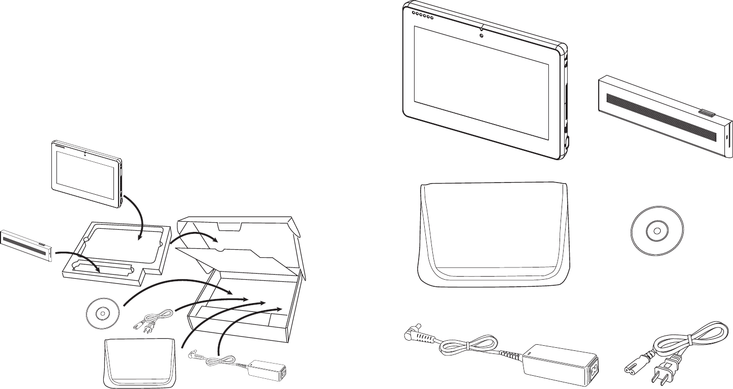
Figure 1.1 Unpacking the
machine
Carefully unpack the machine and keep the packing materials. If you need to ship it in the future, repack it as
shown in Figure 1.1.
2 CHAPTER 1 GETTING STARTED
Checking the package contents
After you unpack the device, check that the following items are included.
If any item is missing or appears damaged, contact your dealer immediately.
AC adapter
Driver CD with drivers and the
user manual PDF file.
EM-200 Battery
Power cord
Protection pack
3
Identifying components
This section describes the parts and connectors on the machine.
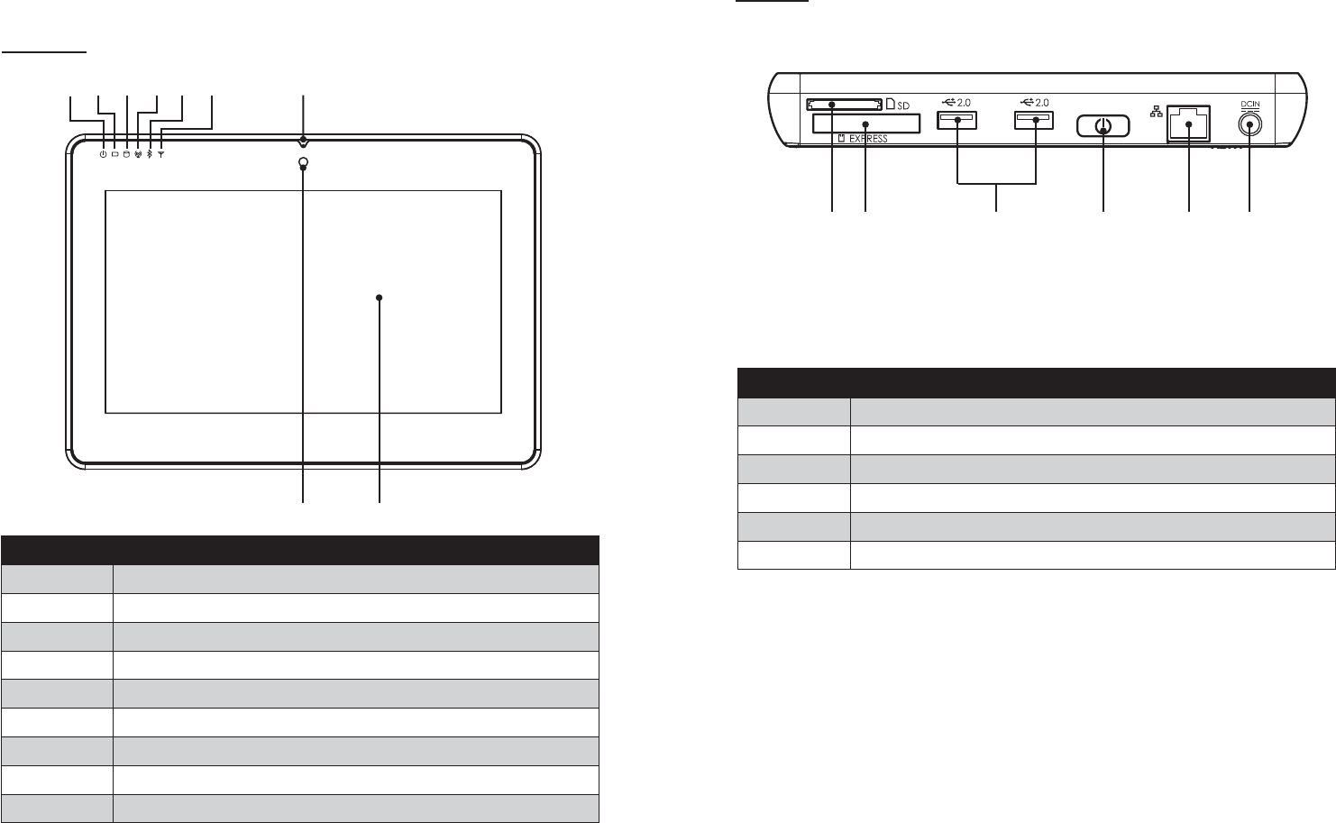
Front view
12 3456 7
98
Figure 1.2 Front view
Component Description
1 Power indicator
2 Battery charging indicator
3 HDD status indicator
4 WiFi On/ Off indicator
5 Bluetooth On/ Off indicator
6Built-in Microphone
7Camera (optional)
810.1-inch touch panel
4 CHAPTER 1 GETTING STARTED
Left view
1
Figure 1.3 Left view
Component Description
1 5-in-1 media card slot
2 Express card 34 slot
3 USB port
4 Power button
5 RJ45 LAN jack
6 DC IN
32456
5
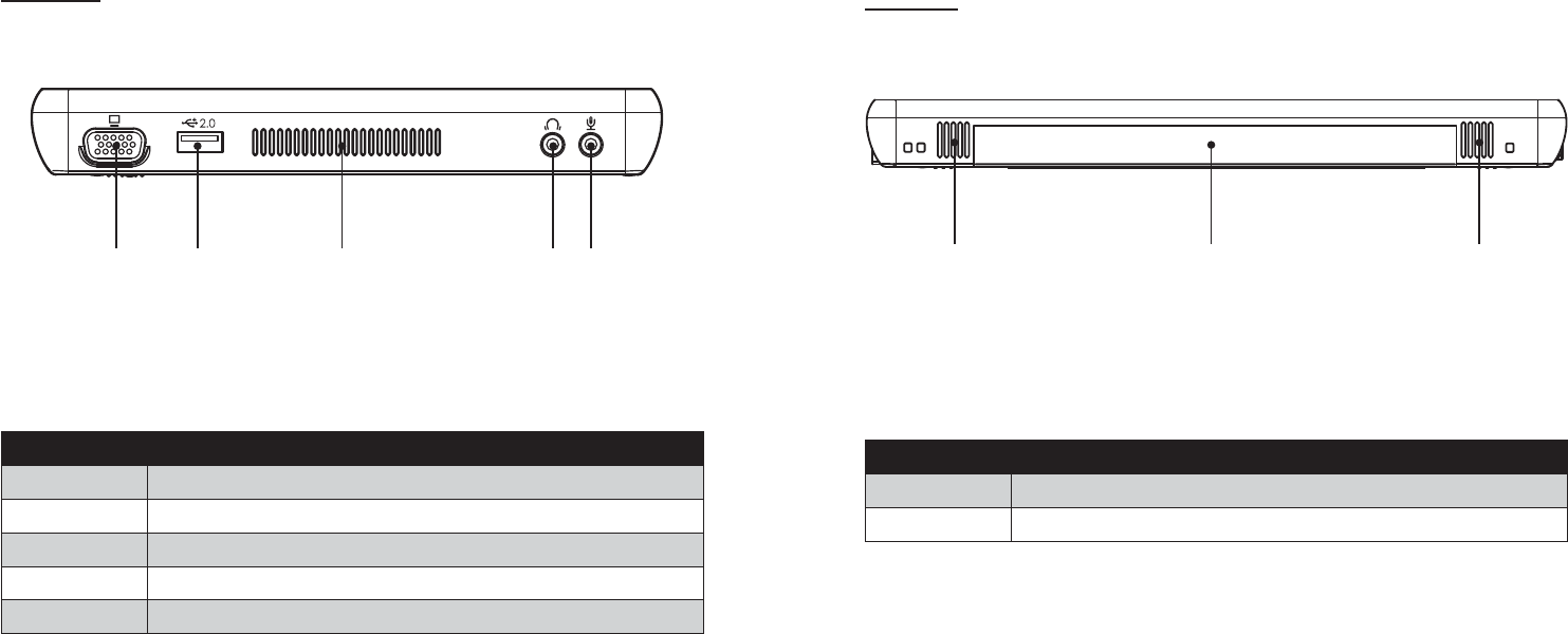
Right view
Figure 1.4 Right view
12 3 45
Component Description
1 VGA port
2 USB port
3 Ventilation hole
4 Headphone jack
5 Microphone jack
6 CHAPTER 1 GETTING STARTED
Rear view
Figure 1.5 Rear view
12 1
Component Description
1 Speaker
2 Battery pack
7
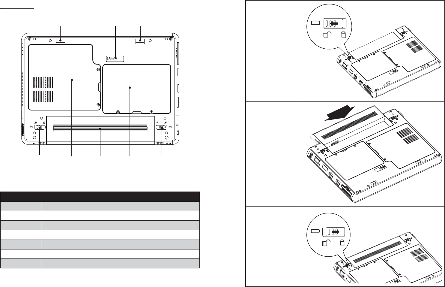
Bottom view
Figure 1.6 Bottom view
121
34567
Component Description
1 Mounting hole
2 Camera (optional)
3 Battery lock switch
4Memory, WiFi module, Bluetooth module slots
5 Battery pack
6 HDD compartment
7 Battery release latch
8 CHAPTER 1 GETTING STARTED
Installing the battery pack
Overturn the EM200 1.
so that the bottom is
facing up toward you, as
shown in the right. Slide
the battery release latch
to the unlock position.
Align EM200 battery 2.
compartment pins to
the battery connector.
Slightly slide and press
the battery pack into the
compartment until the
battery lock switch is
bounced back.
As shown in the right, 3.
slide the battery release
latch to the lock posi-
tion.
9
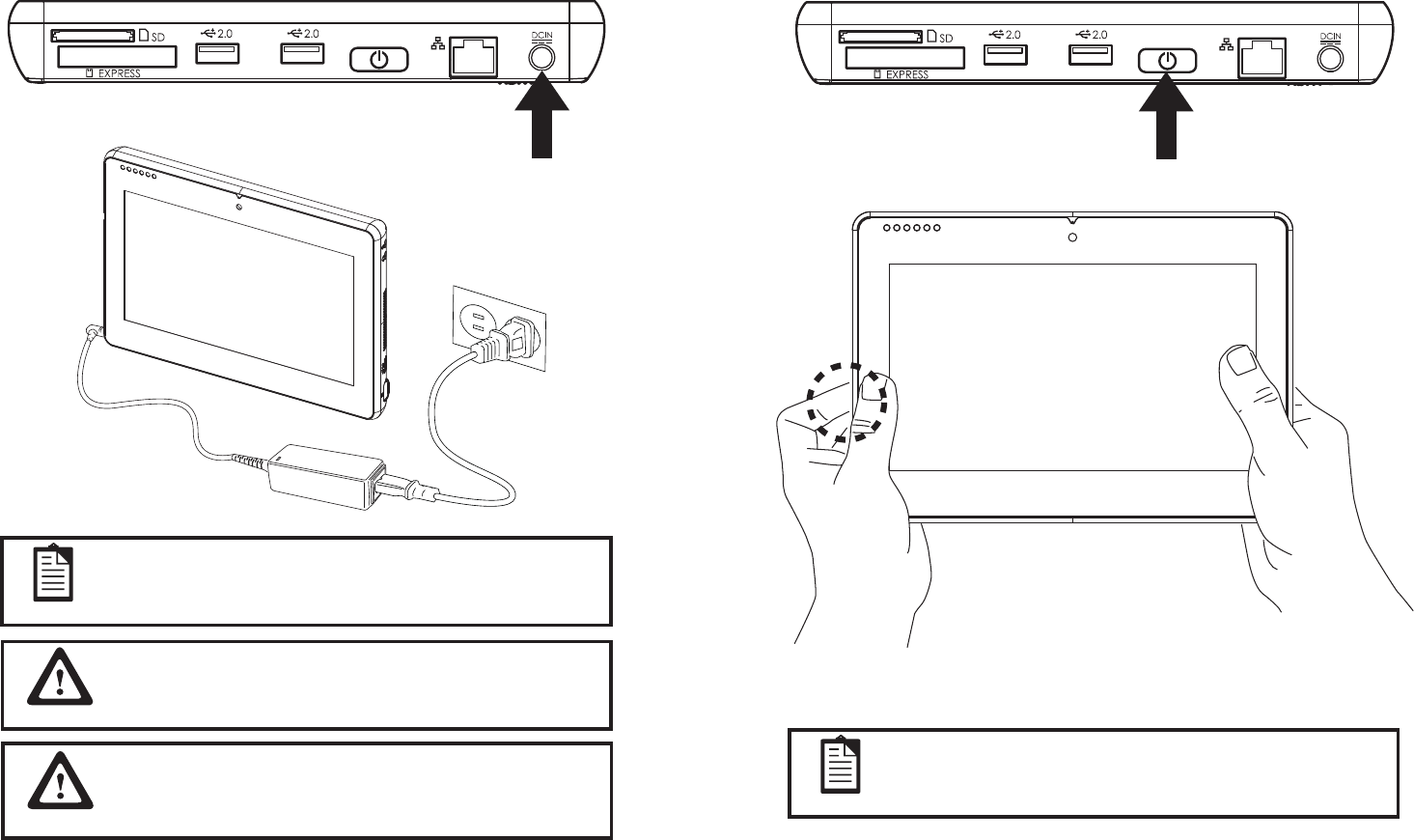
Charging the battery pack
Plug the AC adapter power cord into an electrical outlet, then connect the DC plug of the adapter cable to the
EM-200. It takes approximately 2–4 hours to fully charge the battery for the first time. Subsequent charges
might take longer.
IMPORTANT
To protect and prolong the life of the battery, do not charge it for 24
hours or longer at a time.
NOTE
Charge the battery within a temperature range 0˚C to 45˚C.
Please make sure to perform 3 complete full charge and discharge
cycles to get optimal battery capacity. Failure to comply will result in
shorter battery lifespan.
IMPORTANT
10 CHAPTER 1 GETTING STARTED
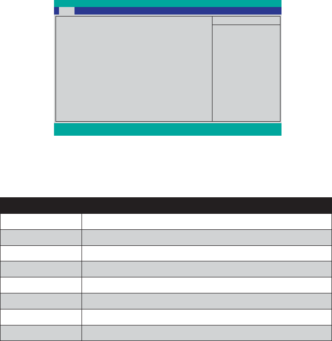
Powering on
The power button located on the left side of the EM200, press the power button the turn it on.
To force power off , long press the power button for 4~5 seconds.
NOTE
11
CHAPTER 2
BIOS SETUP
The primary function of the BIOS (Basic Input and Output System) is to identify and initiate component
hardware. The BIOS parameters are stored in non-volatile BIOS memory (CMOS). CMOS contents don’t get
erased when the computer is turned off. The following topics are described in this chapter.
About the Setup Utility on page 1• 1
Using the USB keyboard on page 1• 1
Main Menu on page 1• 4
Advanced Menu on page 1• 5
Security Menu on page 1• 9
Boot Menu on page 2• 0
Exit Menu on page 2• 2
About the Setup Utility
The BIOS Setup Utility enables you to configure the following items:
Hard drives, diskette drives, and peripherals •
Password protection from unauthorized use•
Power management features•
Boot device priority •
This Setup Utility should be used for the following:
When changing the system configuration •
When a configuration error is detected and you are prompted to make changes to the Setup Utility •
When making changes to the Power Management configuration •
When changing the User or Supervisor password•
When changing the boot priority•
Using the USB keyboard
To enter the BIOS setup must use the external keyboard. Please connect USB keyboard and restart, then refer
to the section “entering the Setup Utility”.
12 CHAPTER 2 BIOS SETUP
Entering the Setup Utility
Press the F2 key during booting to access the BIOS Setup Utility:
BIOS Navigation Keys
The BIOS navigation keys are listed below.
Key Function
←→ Select the menu titles
↑↓ Select the items
Esc Exits the current menu
F1 Displays a screen that describes all key functions
F7/F8 Changes the selected field’s values
F9 Loads the setup default values
F10 Saves the current configuration and exits Setup
Enter Selects or enters submenu
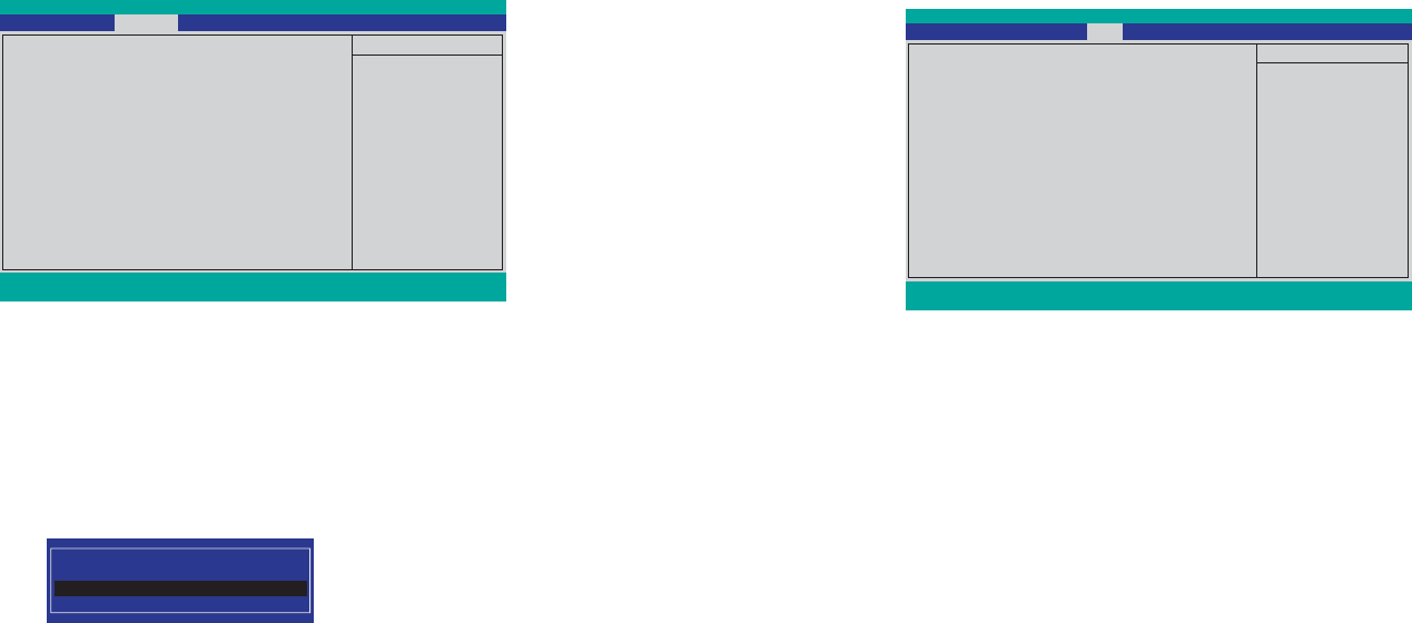
InsydelH2O Setup Utility
System BIOS Version GA-D1USB28 F04
Processor Type Intel(R) Atom(TM) CPU N270
@ 1.66GHz
System Bus Speed 533 MHz
System Memory Speed 533 MHz
Cache RAM 0512 KB
Total Memory 1024 MB
System Time [18:47:25]
System Date [06/21/2009]
Item Specific Help
F1 Help
↑↓
Select Item F7/F8 Change Values F9 Setup Default
ESC Exit
←→
Select Menu Enter Select►Sub-Menu F10 Save and Exit
Main Advanced Security Boot Exit
Main BIOS menuFigure 2.1

13
Using BIOS
When you start the Setup Utility, the main menu appears. A highlight indicates which option is currently
selected. Use the cursor arrow keys to move the highlight to other options. When an option is highlighted,
execute the option by pressing <Enter>.
Some options lead to pop-up dialog boxes that prompt you to verify that you wish to execute that option.
Other options lead to dialog boxes that prompt you for information.
Some options (marked with a triangle ►) lead to submenus that enable you to change the values for the
option. Use the cursor arrow keys to scroll through the items in the submenu.
14 CHAPTER 2 BIOS SETUP
Main Menu
Press right/left arrow key to select the Main menu, which displays the following screen:
System BIOS Version
This item shows the information about BIOS version.
Processor Type
This item shows the CPU type.
System Bus Speed
This item shows the FSB speed.
System Memory Speed
This item shows the memory clock speed.
Cache RAM
This item shows the size of the cache RAM.
Total Memory
This field displays the amount of memory detected by the system during boot.
System Time / Date
The Time and Date items show the current date and time held by the machine. These will be automatically
updated whenever you make changes to the Windows Date and Time Properties utility.
Main menuFigure 2.2
InsydelH2O Setup Utility
System BIOS Version GA-D1USB28 F04
Processor Type Intel(R) Atom(TM) CPU N270
@ 1.66GHz
System Bus Speed 533 MHz
System Memory Speed 533 MHz
Cache RAM 0512 KB
Total Memory 1024 MB
System Time [18:47:25]
System Date [06/21/2009]
Item Specific Help
F1 Help
↑↓
Select Item F7/F8 Change Values F9 Setup Default
ESC Exit
←→
Select Menu Enter Select►Sub-Menu F10 Save and Exit
Main Advanced Security Boot Exit

15
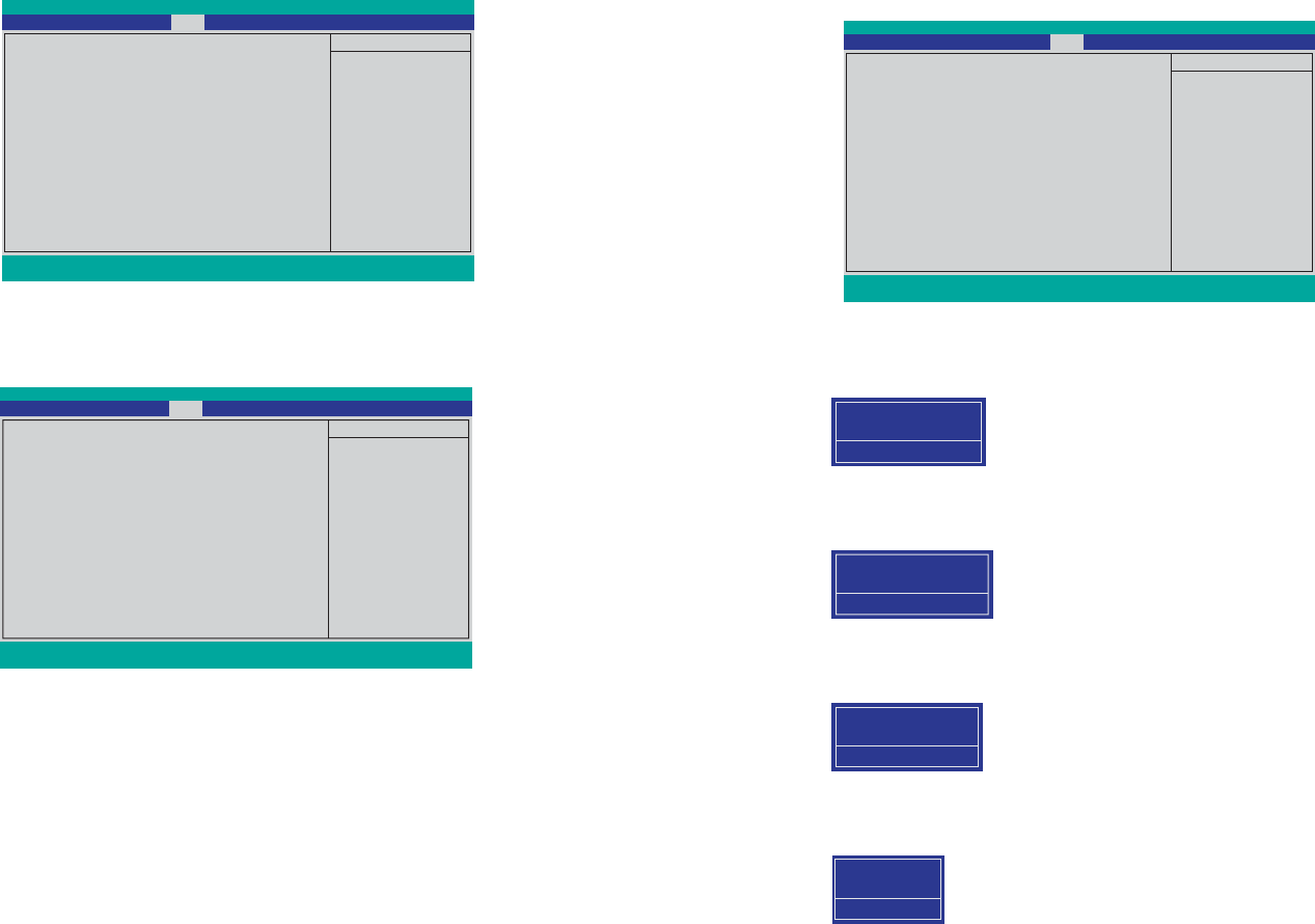
Advanced Menu
Press right/left arrow key to select the Advanced menu, which displays the following screen:
Advanced S3
This item is used to enable/ disable the ACPI S3 mode, it can turn on and off the PC within seconds.
Keyboard Language
This item is used to select the keyboard language of external USB keyboard.
Advanced menuFigure 2.3
InsydelH2O Setup Utility
►Boot Configuration
►IDE Configuration
Advanced S3 [Enabled]
Keyboard Language [US, Chinese]
Item Specific Help
F1 Help
↑↓
Select Item F7/F8 Change Values F9 Setup Default
ESC Exit
←→
Select Menu Enter Select►Sub-Menu F10 Save and Exit
Main Advanced Security Boot Exit
16 CHAPTER 2 BIOS SETUP
► Boot Configuration
Use this submenu to set the boot configuration. Select the item and press <Enter> to open the following menu:
InsydelH2O Setup Utility
Boot Configuration
Numlock [Off]
Item Specific Help
F1 Help
↑↓
Select Item F7/F8 Change Values F9 Setup Default
ESC Exit
←→
Select Menu Enter Select►Sub-Menu F10 Save and Exit
Main Advanced Security Boot Exit
Numlock
This item is used to turn on/off the numlock of the external keyboard at boot.
Boot Figure 2.4
Configuration submenu

17
HDC Configure as
This item is used to select the hard disk interface type.
ATA/IDE Mode
This item is used to select the ATA/IDE mode.
► IDE Configuration
Use this submenu to set the IDE configuration. Select the item and press <Enter> to open the following menu:
InsydelH2O Setup Utility
IDE Configuration
HDC Configure as [SATA Only]
ATA/IDE Mode [Native]
►Channel 1 Master [WDC WD1600BEV1-222CT]
Item Specific Help
F1 Help
↑↓
Select Item F7/F8 Change Values F9 Setup Default
ESC Exit
←→
Select Menu Enter Select►Sub-Menu F10 Save and Exit
Main Advanced Security Boot Exit
IDE Figure 2.5
Configuration submenu
18 CHAPTER 2 BIOS SETUP
Channel 1 Master
Displays the name of the current hard disk device in channel 1 master.
Type:
If you leave this item at Auto, the system will automatically detect and configure the device it channel
1 master. If you change the value to User Defined and then manually configure the drive by entering the
characteristics of the drive in the fields described below:
32Bit I/O – when enabled, allows the system to improve the hard drive performance for 32Bit OS.•
Block Mode – when enabled, allows the system to perform accesses to the hard disk in block mode.•
Transfer Mode – displays the data transfer mode.•
S.M.A.R.T – when enabled, allows the system to support S.M.A.R.T (Self-Monitoring, Analysis, and •
Reporting Technology) for hard disk device.
Security Mode – displays the security mode status.•
► Channel 1 Master
Use this submenu to set the hard disk drive, Select the item and press <Enter> to open the following menu:
InsydelH2O Setup Utility
Channel 1 Master [WDC WD1600BEVT-22ZCT]
Type : [Auto]
Transfer Mode: [Auto]
32Bit I/O: <Enabled>
Block Mode: <Enabled>
Transfer Mode: <Ultra DMA ATA-100>
S.M.A.R.T <Enabled>
Security Mode: Uninstall
Item Specific Help
F1 Help
↑↓
Select Item F7/F8 Change Values F9 Setup Default
ESC Exit
←→
Select Menu Enter Select►Sub-Menu F10 Save and Exit
Advanced
Channel 1 Figure 2.6
Master submenu
19
Security Menu
The security system allows you to set a password to prevent unauthorized access to BIOS. Press right/left
arrow key to select the Security menu, which displays the following screen:
Supervisor/ User Password
These two fields indicate if the Supervisor/ User Passwords are set or not.
Installed: System Password is set. Not Installed: System Password is not set.
Set Supervisor and User Passwords
These items can be used to install a password. A Supervisor password takes precedence over a User password,
and the Supervisor can limit the activities of a User. To install a password, follow these steps:
1. Highlight the item Set Supervisor/User Password on the Security menu and press <Enter>.
2. The password dialog box appears.
Please type in your new password
3. If you are installing a new password, type in the password. You can type up to eight alphanumeric
characters. Symbols are ignored. The Set Supervisor/User Password item differentiates between
upper and lower case characters. Press <Enter> after you have typed in the password. To confirm the
password, type the password again and press <Enter>. To clear the password, leave the dialog box
blank, press <Enter>, when the confirm box appears, press <Enter> again.
4. Write the passwords down and keep them in a safe place.
Power on password
When enabled, system will ask input password on post time. When disabled, system will ask input password
when go to Setup Utility.
User Access Level
This item allows you to configure the user access level.
View Only - users can only view the Bios settings and can not change the settings.
Limited - allows users to change some settings.
Full - users can change all of the BIOS settings.
Security menuFigure 2.7
InsydelH2O Setup Utility
Supervisor Password : Not Installed
User Password : Not Installed
Set Supervisor Password
Set User Password
Item Specific Help
F1 Help
↑↓
Select Item F7/F8 Change Values F9 Setup Default
ESC Exit
←→
Select Menu Enter Select►Sub-Menu F10 Save and Exit
Main Advanced Security Boot Exit
20 CHAPTER 2 BIOS SETUP
Boot Menu
This menu allows the user to set the boot-related options. Press right/left arrow key to select the Boot menu,
which displays the following screen:
InsydelH2O Setup Utility
Quiet Boot [Enabled]
►Boot Type
Item Specific Help
F1 Help
↑↓
Select Item F7/F8 Change Values F9 Setup Default
ESC Exit
←→
Select Menu Enter Select►Sub-Menu F10 Save and Exit
Main Advanced Security Boot Exit
Boot MenuFigure 2.8
Quiet Boot
When enabled, system will boot without message. In contrast, when disabled, system will boot in text mode.
21
Boot Device Figure 2.9
Priority submenu
Boot Type Figure 2.10
Order submenu
InsydelH2O Setup Utility
Boot Device Priority
►Boot Type Order
Item Specific Help
F1 Help
↑↓
Select Item F7/F8 Change Values F9 Setup Default
ESC Exit
←→
Select Menu Enter Select►Sub-Menu F10 Save and Exit
Main Advanced Security Boot Exit
InsydelH2O Setup Utility
Boot Type Order
Hard Disk Drive
USB CD/DVD ROM Driver
USB Memory
Others
Item Specific Help
F1 Help
↑↓
Select Item F7/F8 Change Values F9 Setup Default
ESC Exit
←→
Select Menu Enter Select►Sub-Menu F10 Save and Exit
Boot
►Boot Device Priority
Select the Boot Type item and press <Enter> to open the following menu:
►Boot Type Order
This submenu allows the user to decide the order of boot devices to load the operating system. Select the Boot
Type item and press <Enter> to open the following menu:
Select a media type, and then use F7 or F8 key to move up or down the item in order to arrange the boot
priority.
22 CHAPTER 2 BIOS SETUP
Exit Menu
This menu allows the user to save CMOS setting and exit the Setup Utility. Press right/left arrow key to select
the Exit menu, which displays the following screen:
Exit MenuFigure 2.11
Exit Saving Changes
Allows the user to save changes to CMOS and reboot the system. The following message is prompted when
the user presses <Enter> on the item.
Exit Saving Changes
[Yes] [No]
Exit Discarding Changes
Allows the user to exit Setup without saving changes to CMOS. The following message is prompted when
user presses <Enter> on the item.
Exit Discarding Changes
[Yes] [No]
Load Optimal Defaults
Allows the user to load the default value in CMOS Setup. The following message is prompted when the user
presses <Enter> on this item.
Load Optimal Defaults
[Yes] [No]
Discard Changes
Allows the user to discard the changes. The following message is prompted when the user presses <Enter> on
this item.
Discard Changes
[Yes] [No]
InsydelH2O Setup Utility
Exit Saving Changes
Exit Discarding Changes
Load Optimal Defaults
Discard Changes
Item Specific Help
F1 Help
↑↓
Select Item F7/F8 Change Values F9 Setup Default
ESC Exit
←→
Select Menu Enter Select►Sub-Menu F10 Save and Exit
Main Advanced Security Boot Exit
23
CHAPTER 3
UPGRADING COMPONENTS
This chapter describes how to upgrade components for the EM-200. The following topics are described.
Safety and precautions on page 2• 3
Before you begin on page 2• 4
Upgrading the hard drive on page 2• 5
Upgrading the memory module on page 2• 7
Upgrading the Mini-PCIE card on page 2• 8
Safety and precautions
Computer components and electronic circuit boards can be damaged by discharges of static electricity.
Working on computers that are still connected to a power supply can be extremely dangerous. Follow these
guidelines to avoid damage to the computer or injury to yourself.
Always disconnect the unit from the power outlet.•
Leave all components inside the static-proof packaging that they ship with until they are ready for instal-•
lation.
After replacing optional devices, make sure all screws, springs, or other small parts are in place and are •
not left loose inside the case. Metallic parts or metal flakes can cause electrical shorts.
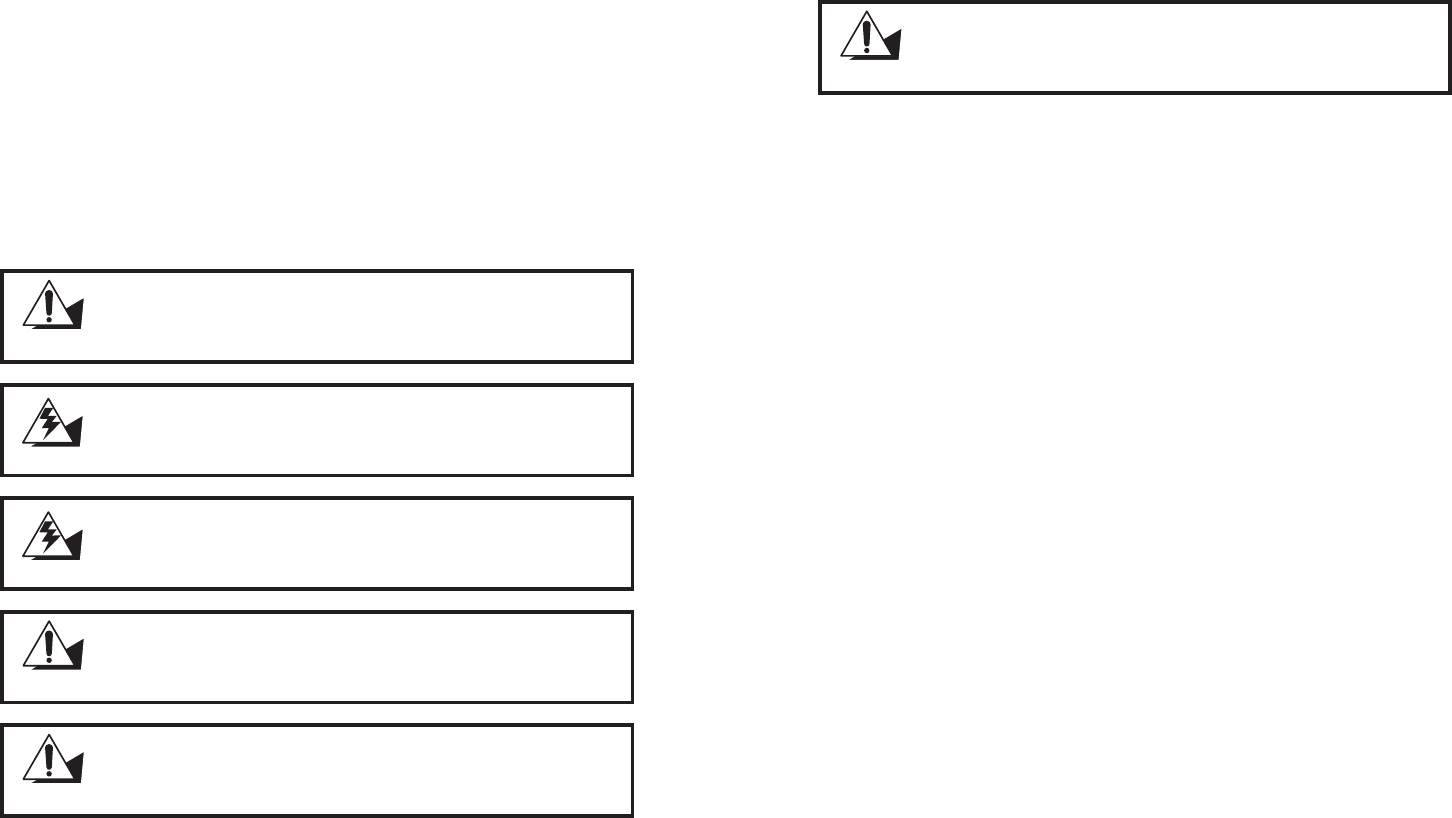
If the LCD breaks and fluid gets onto your hands or into your eyes,
immediately wash with water and seek medical attention.
WARNING
CAUTION
Only qualified personnel should perform repairs on the machine.
Damage due to unauthorized servicing is not covered by the warranty.
If you are not confident of installing a hard drive, memory card or LAN
card, we recommend that you refer the job to qualified personnel.
The inverter card has high voltage. Do not touch the inverter card while
power is connected to the machine. Unplug the power cord before
attempting to replace any part.
WARNING
CAUTION
To prevent static damage to components, wear a grounded wrist strap.
Alternatively, discharge any static electricity by touching the bare metal
chassis of the unit case, or the bare metal body of any other grounded
appliance.
CAUTION
Hold electronic circuit boards by the edges only. Do not touch the
components on the board unless it is necessary to do so. Do not flex or
stress the circuit board. Do not hold components such as a processor
by its pins; hold it by the edges.
24 CHAPTER 3 UPGRADING COMPONENTS
Before you begin
Make sure you have a stable, clean working environment. Dust and dirt can get into components and may
cause malfunction. Adequate lighting and proper tools can prevent you from accidentally damaging the
internal components.
Most of the electrical and mechanical connections can be disconnected by using your fingers. It is
recommended that you do not use needle-nosed pliers to disconnect connectors as these can damage the soft
metal or plastic parts of the connectors.
CAUTION
To prevent scratching the case of the machine, make sure the worktop
surface is clean and flat.
25
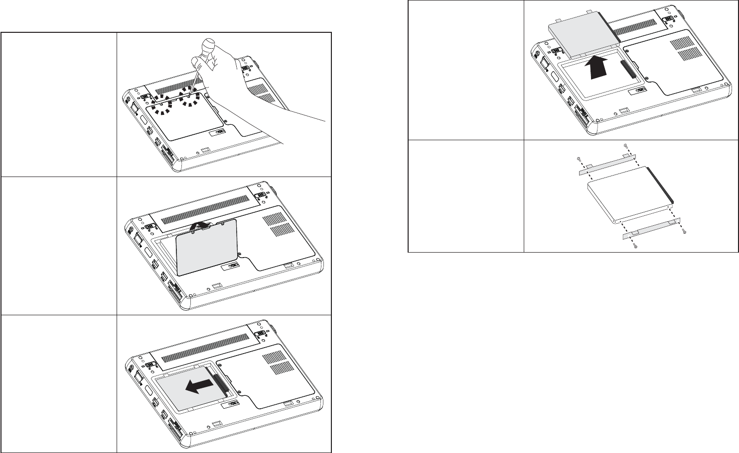
Upgrading the hard drive
Refer to the following to remove and replace the hard drive.
Turn off the EM-200.1.
Disconnect the AC adapter 2.
cable.
Overturn the EM200.3.
Remove the two screws as 4.
shown in the right.
Open and remove the hard drive 5.
compartment cover.
Slide the hard drive to 6.
disconnect.
26 CHAPTER 3 UPGRADING COMPONENTS
Remove the hard drive.7.
Remove the four screws, then 8.
remove the hard drive out from
the tray.
To replace the hard drive, reverse the above procedure.
27
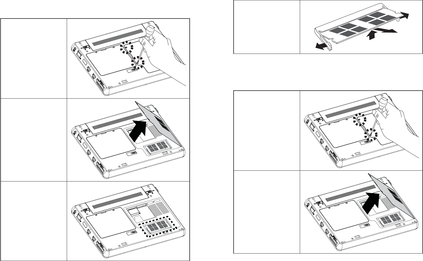
Upgrading the memory module
Refer to the following to remove and replace the memory.
Turn off the EM-200.1.
Disconnect the AC adapter 2.
cable.
Overturn the EM200.3.
Remove the two screws as 4.
shown in the right.
Open and remove the memory 5.
module compartment cover.
Locate the memory module, as 6.
shown in the right.
28 CHAPTER 3 UPGRADING COMPONENTS
Pop out the two silver latches 7.
holding the memory module
into place. The module pops
up. Grasp the outer edges of the
memory module with thumb
and forefinger, and then gently
remove it.
To replace the memory module, reverse the above procedure.
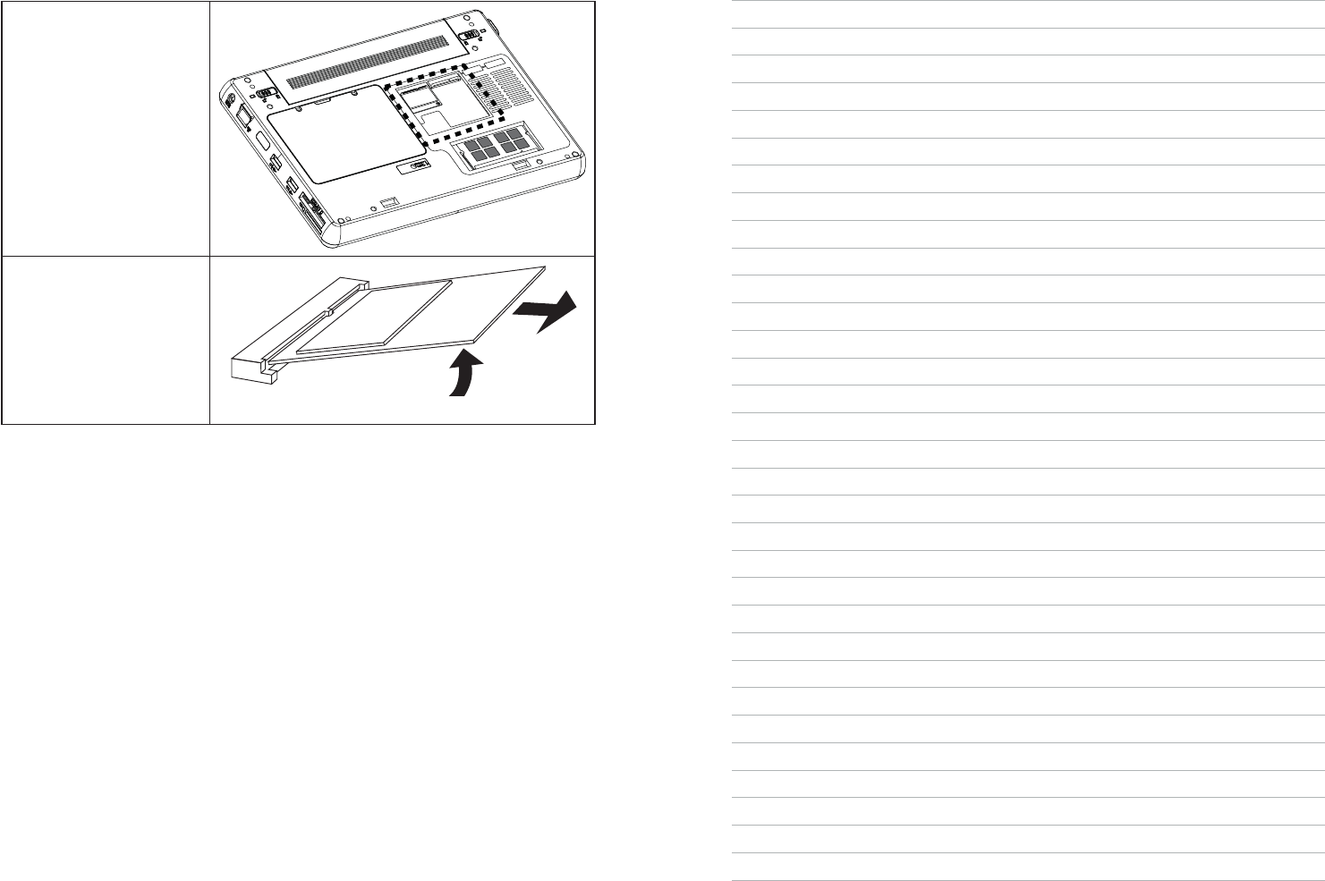
Upgrading the Mini-PCIE card
Refer to the following to remove and replace the PCIE card.
Turn off the EM-200.1.
Disconnect the AC adapter 2.
cable.
Overturn the EM200.3.
Remove the two screws as 4.
shown in the right.
Open and remove the Mini-5.
PCIE card compartment cover.
29
Locate the Mini-PCIE card, as 6.
shown in the right.
Remove the screw on the Mini-7.
PCIE card, Mini-PCIE will pop
up 45 degree.
When it pops up, gently remove 8.
it.
To replace the Mini-PCIE card, reverse the above procedure.
30 CHAPTER 3 UPGRADING COMPONENTS

31
APPENDIX
This appendix describes locating and solving problems that you may encounter while using the EM-200.
Troubleshooting
Often after time spent troubleshooting, the problem is traced to something as simple as a loose connection.
Check the following before proceeding to the problem-specific solutions.
Tips for Troubleshooting
In each problem-specific section, try the steps in the order suggested. This may help you to solve the problem
more quickly. Try to pin point the problem and thus avoid replacing non-defective parts. For example, if you
replace batteries and the problem remains, put the original batteries back and go to the next step.
Keep a record of the steps you take when troubleshooting: The information may be useful when calling for
technical support or for passing on to service personnel.
Use some other electrical device to confirm that the electrical outlet is working.•
Ensure all connections are securely attached.•
32APPENDIX
General Problems
Refer to the following general problems you may encounter.
PROBLEM SOLUTION
The display screen is dark. Make sure that the EM-200 is not in suspend
mode.
An incorrect date and time are displayed. Set the date and time in BIOS or Operation
System.
Cannot be turned off after crash. Long press the power button for 4 seconds to force
shutdown.
Cannot be powered on Connect the AC adapter, if it can be powered on,
there is insufficient battery power. If it still unable
to be powered on after charging, please have the
EM-200 serviced.

33
Having the EM-200 Serviced
If you are unable to solve the problem, you should have the terminal serviced. Pack the terminal in the
original carton. (See “Unpacking the EM-200” on page 1.) Include a description of the problem and a
checklist of the steps you took when trying to fix the problem. The information may be useful to the service
personnel. Return the terminal to the place you purchased it.
34APPENDIX
Specification
Processor Intel Atom 1.6GHz Processor (N270)
BIOS 1024K BB Flash ROM
Chipset Intel 945GSE
Memory Memory DDRII SO-DIMM X 1, 1GB, support up to 2GB
LCD Display 10.1” TFT-LCD, 1024x600, 200 nits, LED backlight
With Touch Panel Resistive touch
Graphics Integrated in Intel 945GSE graphics controller
Hard Disk Drive One 2.5" 160GB SATA HDD
Bluetooth Bluetooth 2.1
LAN & WiFi
Ethernet 10/100 Base T
IEEE 802.11b/g/n
Interface I/O Port
5-in-1 Media Card Slot x 1
Mini-PCIe Slot x 2 (Internal)
Express Card 34 Slot x 1
USB Port x 3
Audio Jack x 2 (Mic-in and Headphone out)
VGA D-Sub x 1
DC-in x1
Speaker 1 Watt x 2
Input Devices
Touch panel
Internal Mic-in
System Status LED Power on/Suspend, Battery Charging, HDD Access, RF, Caps Lock, Number Lock
Buttons & Switch Power on/off switch
WebCam 1.3M Pixel CMOS webcam integrated (optional)
Battery Pack DC 7.4v, 4,500mA Li-polymer battery
Battery life up to 3 hrs (estimate)
Dimensions (W x
H x T) 189 x 268 x 25.7mm
Weight 1,250g