Parts Express PMA8 Speaker Box User Manual 716 1708046 PMA8 A3
Parts Express International Inc. Speaker Box 716 1708046 PMA8 A3
UserManual.wiki
>
Parts Express
>
PMA8 User Manual
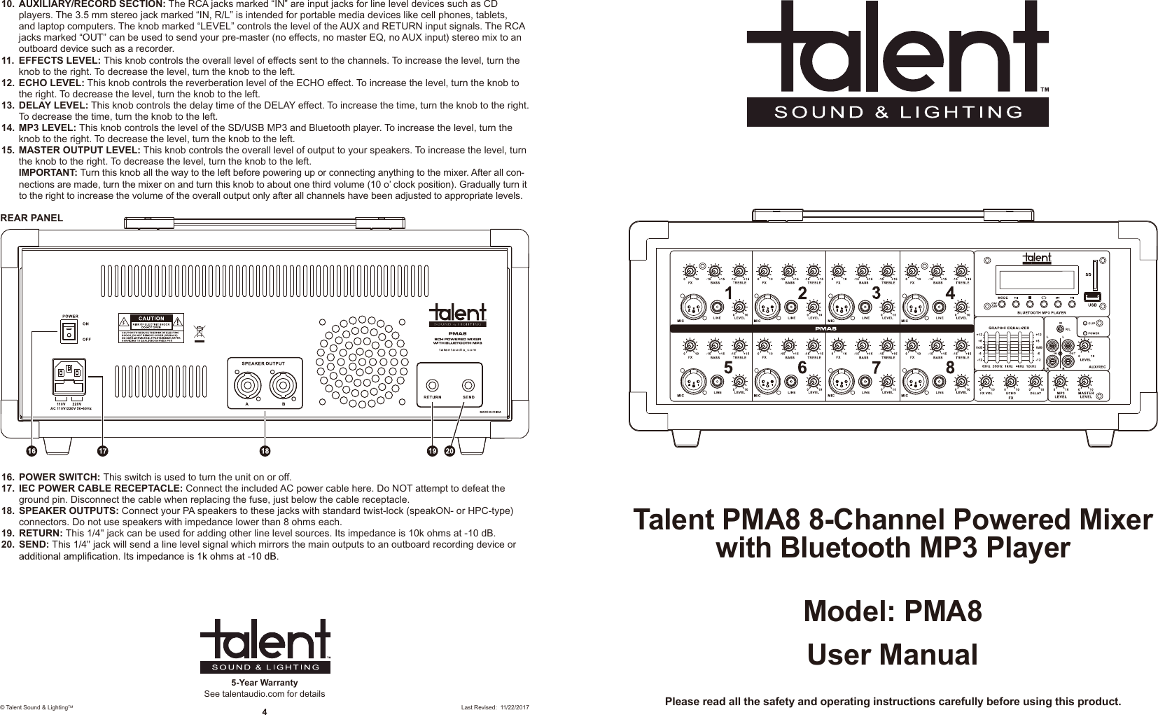
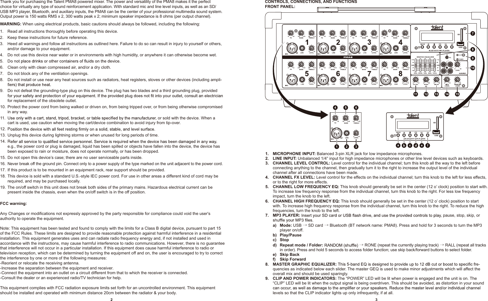
User Manual
Navigation menu
Upload a User Manual
Namespaces
Wiki Guide
HTML
PDF
Info
Views
User Manual
Discussion / Help
Navigation