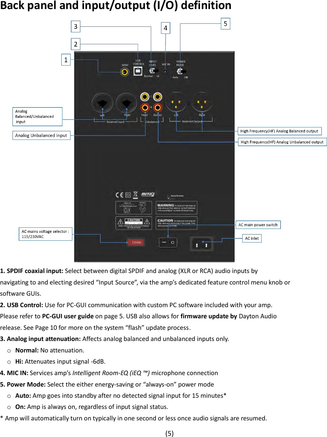
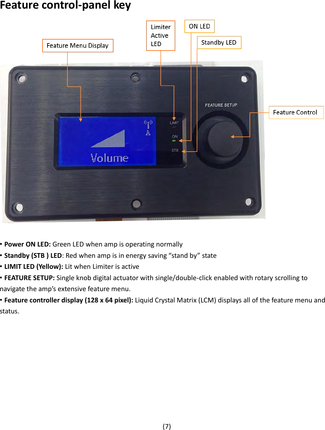
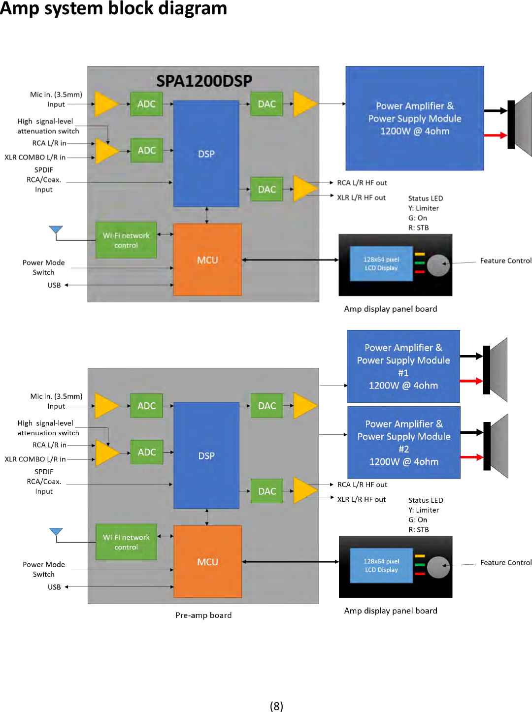
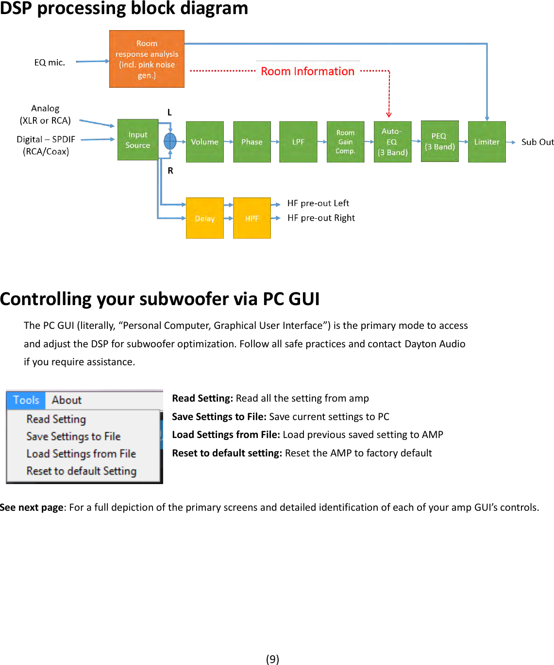
Parts Express SPA Subwoofer Amplifier User Manual
PARTS EXPRESS INTERNATIONAL Subwoofer Amplifier
UserManual.wiki
>
Parts Express
>
SPA User Manual
User manual
Navigation menu
Upload a User Manual
Namespaces
Wiki Guide
HTML
PDF
Info
Views
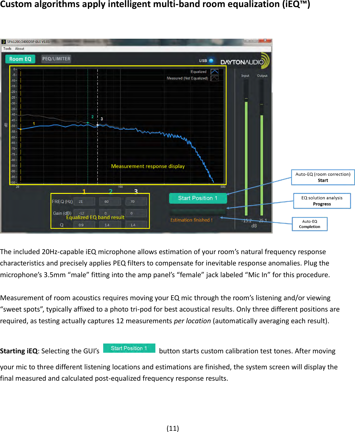
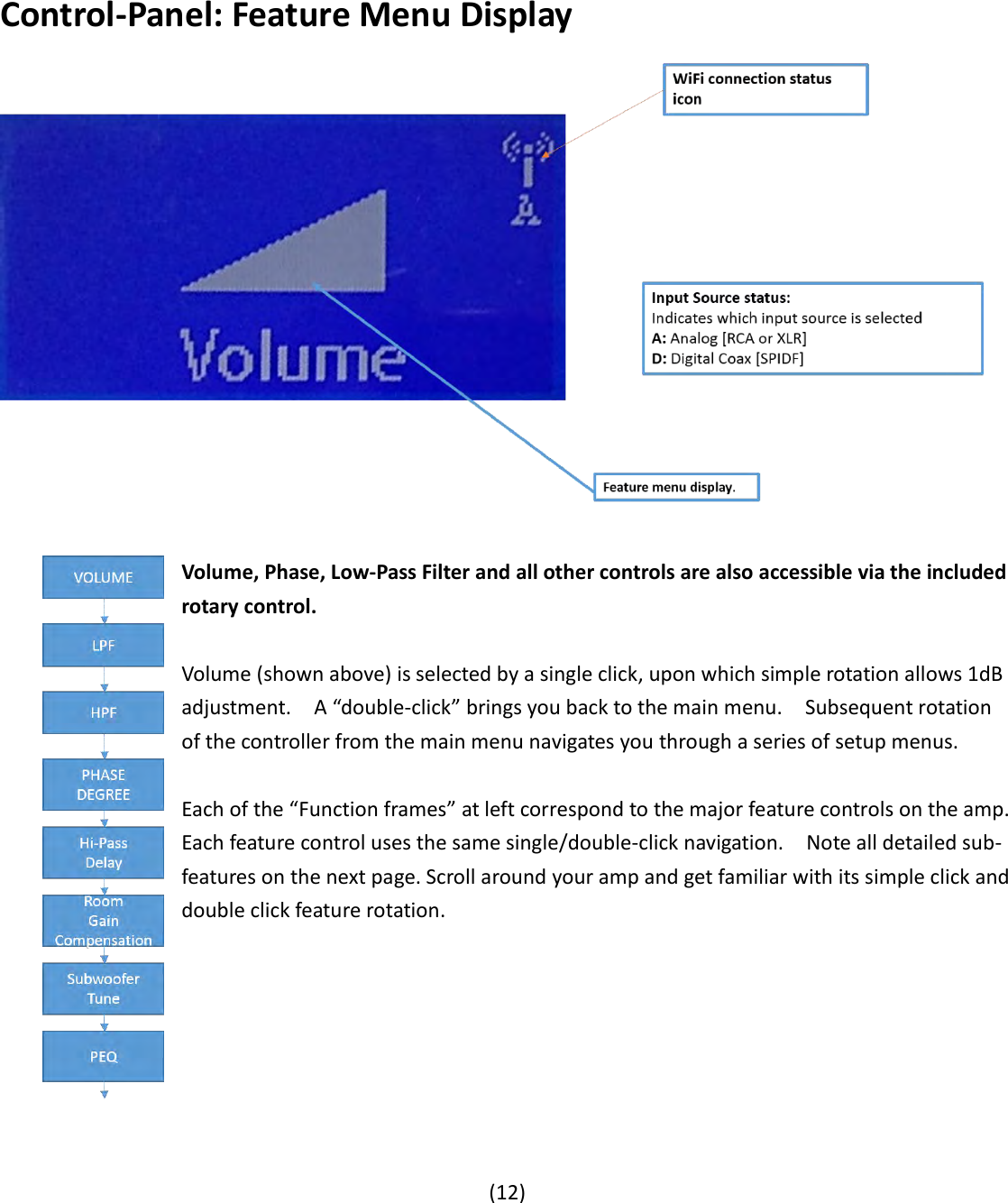
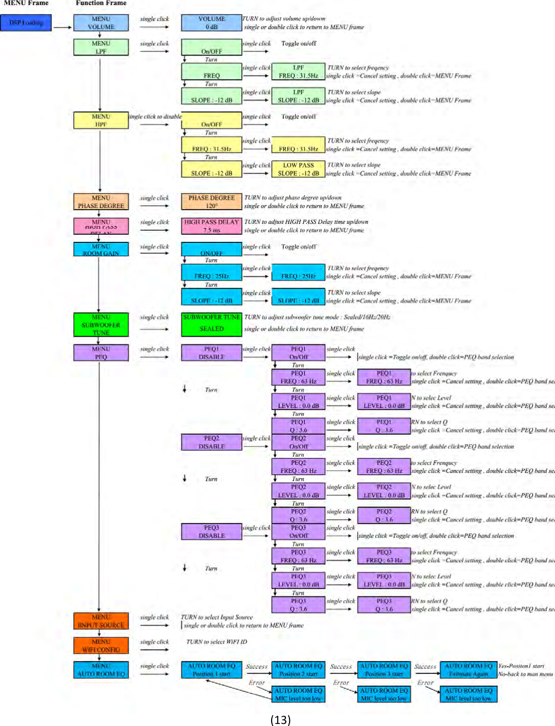
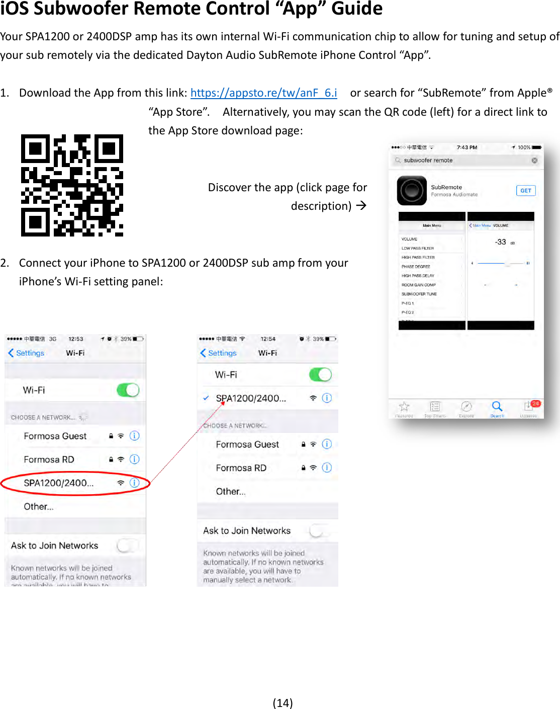
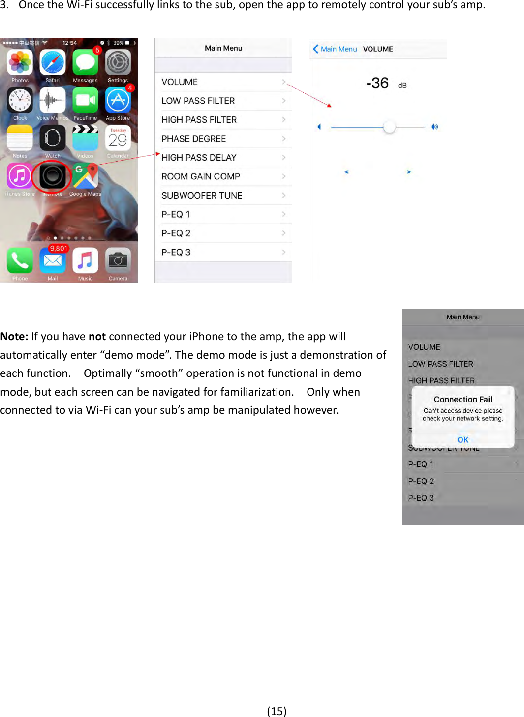
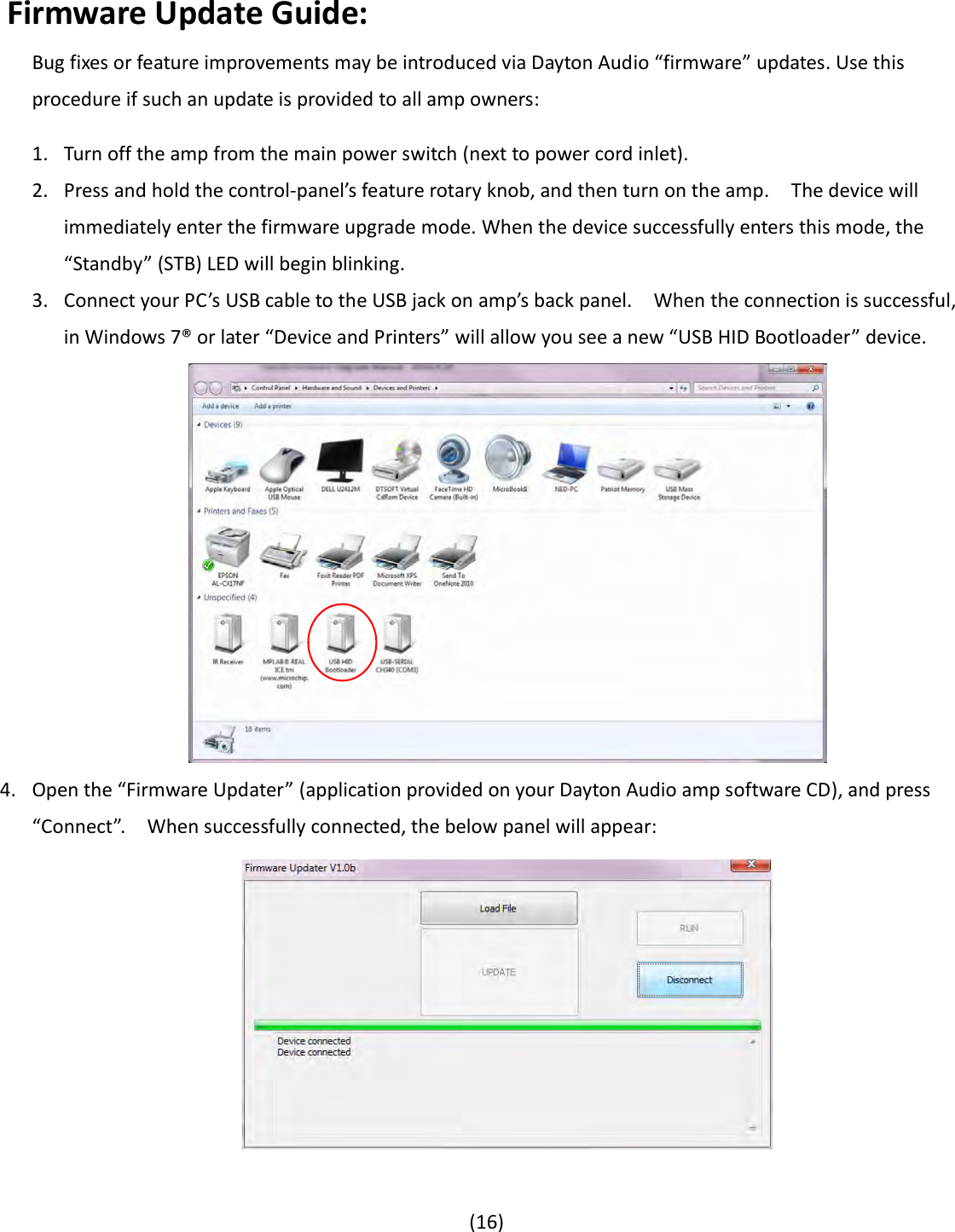
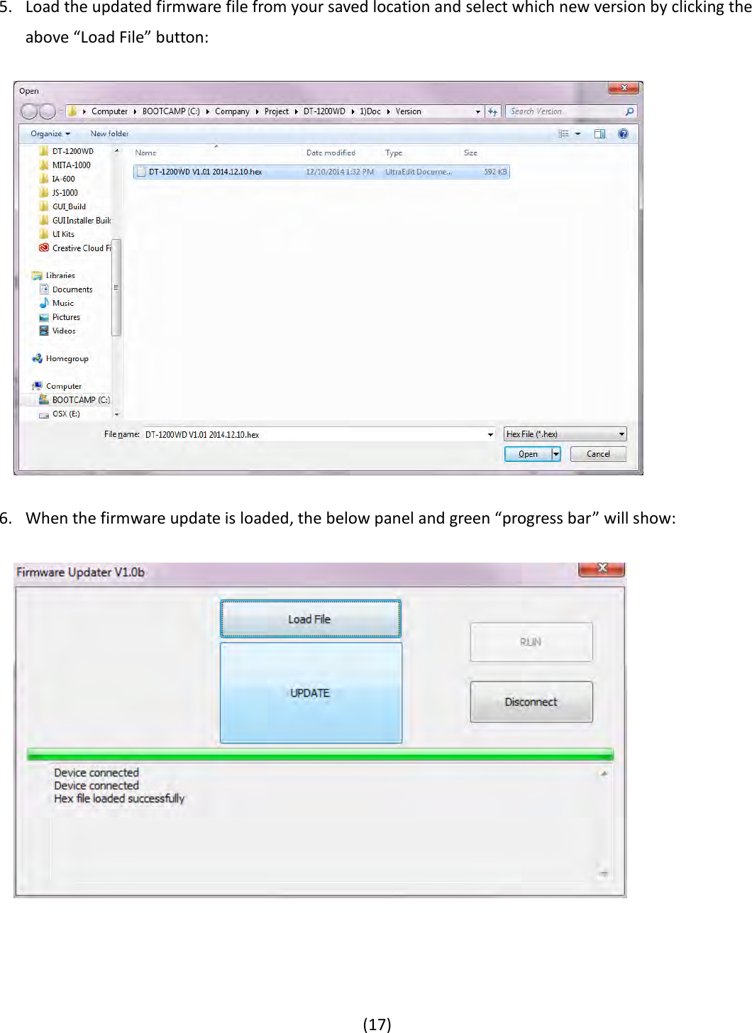
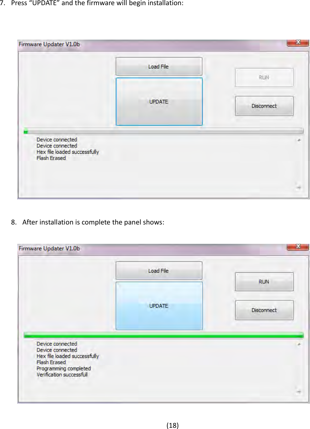
User Manual
Discussion / Help
Navigation