Parts Express SPA Subwoofer Amplifier User Manual
PARTS EXPRESS INTERNATIONAL Subwoofer Amplifier
User manual
(1)
(2)
FCC STATEMENT
1. This device complies with Part 15 of the FCC Rules. Operation is subject to the following two
conditions:
(1) This device may not cause harmful interference, and
(2) This device must accept any interference received, including interference that may cause
undesired operation.
2. Changes or modifications not expressly approved by the party responsible for compliance could
void the user’s authority to operate the equipment.
This equipment has been tested and found to comply with the limits for a Class B digital device,
pursuant to part 15 of the FCC Rules. These limits are designed to provide reasonable protection
against harmful interference in a residential installation. This equipment generates, uses and can
radiate radio frequency energy and, if not installed and used in accordance with the instructions,
may cause harmful interference to radio communications. However, there is no guarantee that
interference will not occur in a particular installation. If this equipment does cause harmful
interference to radio or television reception, which can be determined by turning the equipment off
and on, the user is encouraged to try to correct the interference by one or more of the following
measures:
—Reorient or relocate the receiving antenna.
—Increase the separation between the equipment and receiver.
—Connect the equipment into an outlet on a circuit different from that to which the receiver is
connected.
—Consult the dealer or an experienced radio/ TV technician for help.
FCC Radiation Exposure Statement: (mobile device)
This equipment complies with FCC radiation exposure limits set forth for an uncontrolled
environment. In order to avoid the possibility of exceeding the FCC radio frequency exposure
limits, Human proximity to the antenna shall not be less than 20cm (8 inches) during normal
operation.
(4)
Operating Guide: Dayton Audio SPA1200/2400DSP
Subwoofer Power Amplifiers
Table of Contents
Back panel and input/output (I/O) definition ........................................................... 5
SPA1200DSP and SPA2400DSP wiring ...................................................................... 6
Feature control-panel key ......................................................................................... 7
Amp system block diagram ....................................................................................... 8
Controlling your subwoofer via PC GUI ...................................................................... 9
Feature menu display .............................................................................................. 12
iOS remote control “app” guide ............................................................................. 14
Firmware update guide ........................................................................................... 16
(5)
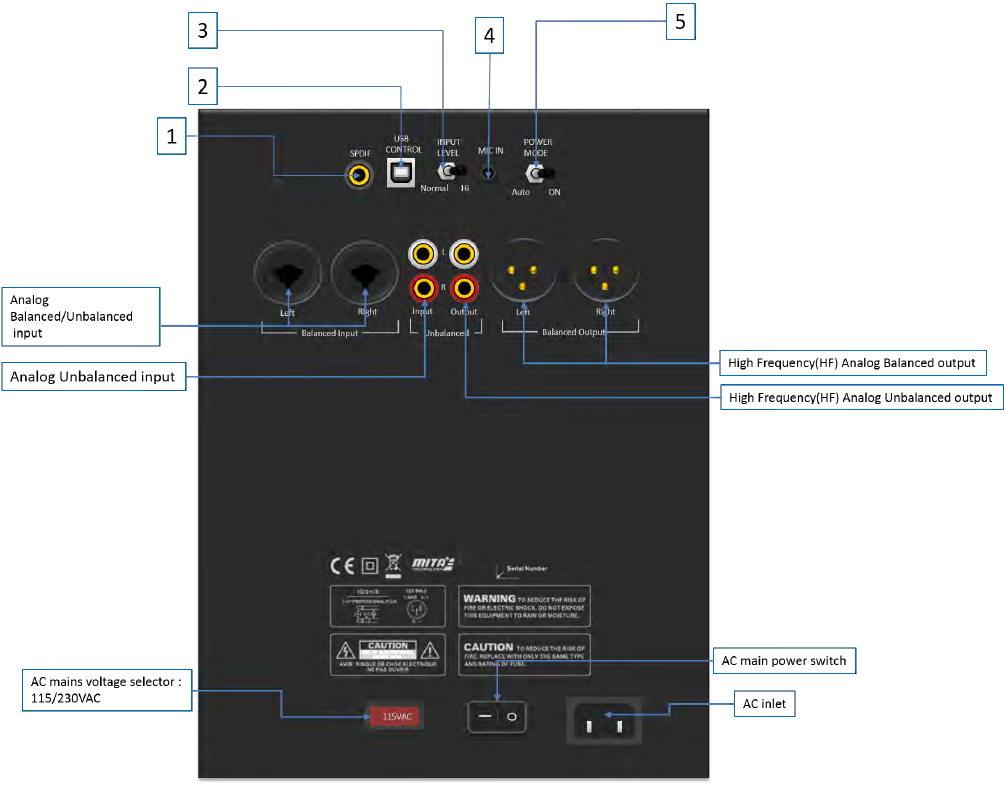
Back panel and input/output (I/O) definition
1. SPDIF coaxial input: Select between digital SPDIF and analog (XLR or RCA) audio inputs by
navigating to and electing desired “Input Source”, via the amp’s dedicated feature control menu knob or
software GUIs.
2. USB Control: Use for PC-GUI communication with custom PC software included with your amp.
Please refer to PC-GUI user guide on page 5. USB also allows for firmware update by Dayton Audio
release. See Page 10 for more on the system “flash” update process.
3. Analog input attenuation: Affects analog balanced and unbalanced inputs only.
o Normal: No attenuation.
o Hi: Attenuates input signal -6dB.
4. MIC IN: Services amp’s Intelligent Room-EQ (iEQ ™) microphone connection
5. Power Mode: Select the either energy-saving or “always-on” power mode
o Auto: Amp goes into standby after no detected signal input for 15 minutes*
o On: Amp is always on, regardless of input signal status.
* Amp will automatically turn on typically in one second or less once audio signals are resumed.
(6)
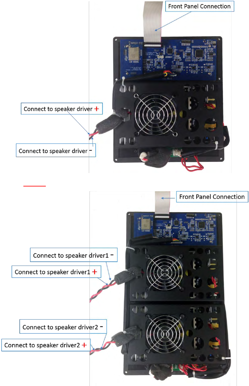
SPA1200DSP and SPA2400DSP wiring
SPA1200DSP
SPA2400DSP - NOTE: Do NOT bridge outputs. Dual voice coil and dual driver loads only!
(7)
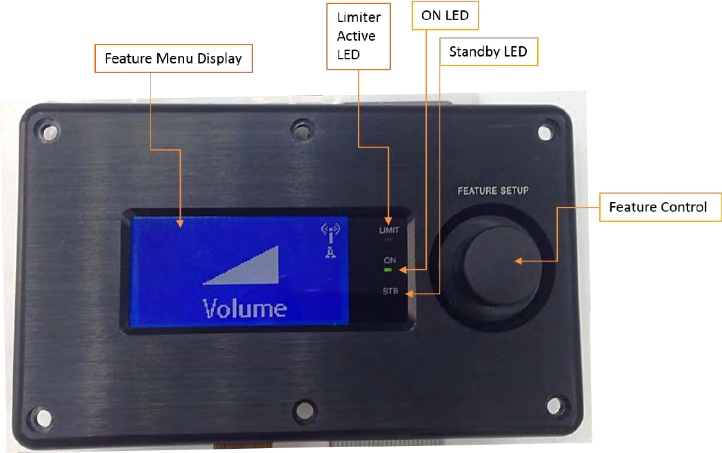
Feature control-panel key
• Power ON LED: Green LED when amp is operating normally
• Standby (STB ) LED: Red when amp is in energy saving “stand by” state
• LIMIT LED (Yellow): Lit when Limiter is active
• FEATURE SETUP: Single knob digital actuator with single/double-click enabled with rotary scrolling to
navigate the amp’s extensive feature menu.
• Feature controller display (128 x 64 pixel): Liquid Crystal Matrix (LCM) displays all of the feature menu and
status.
(8)
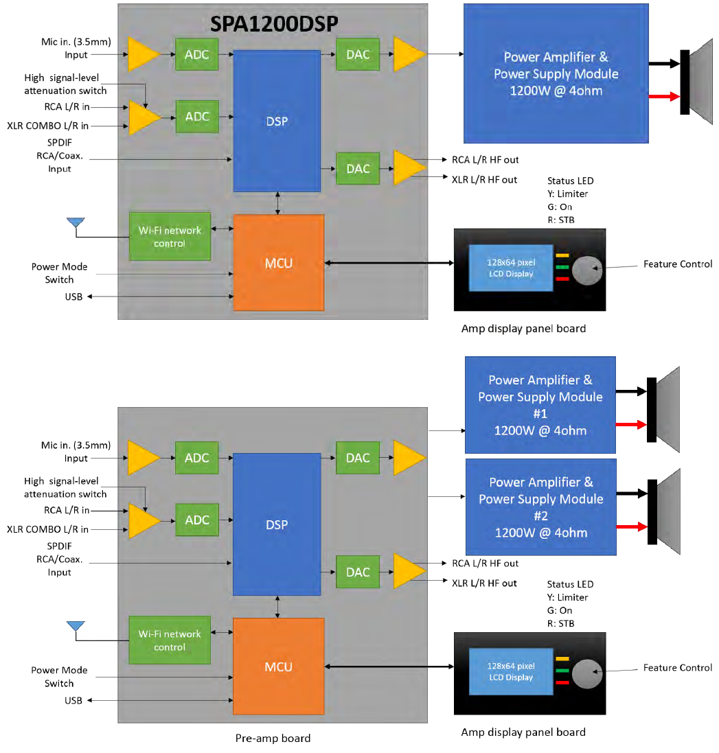
Amp system block diagram
(9)
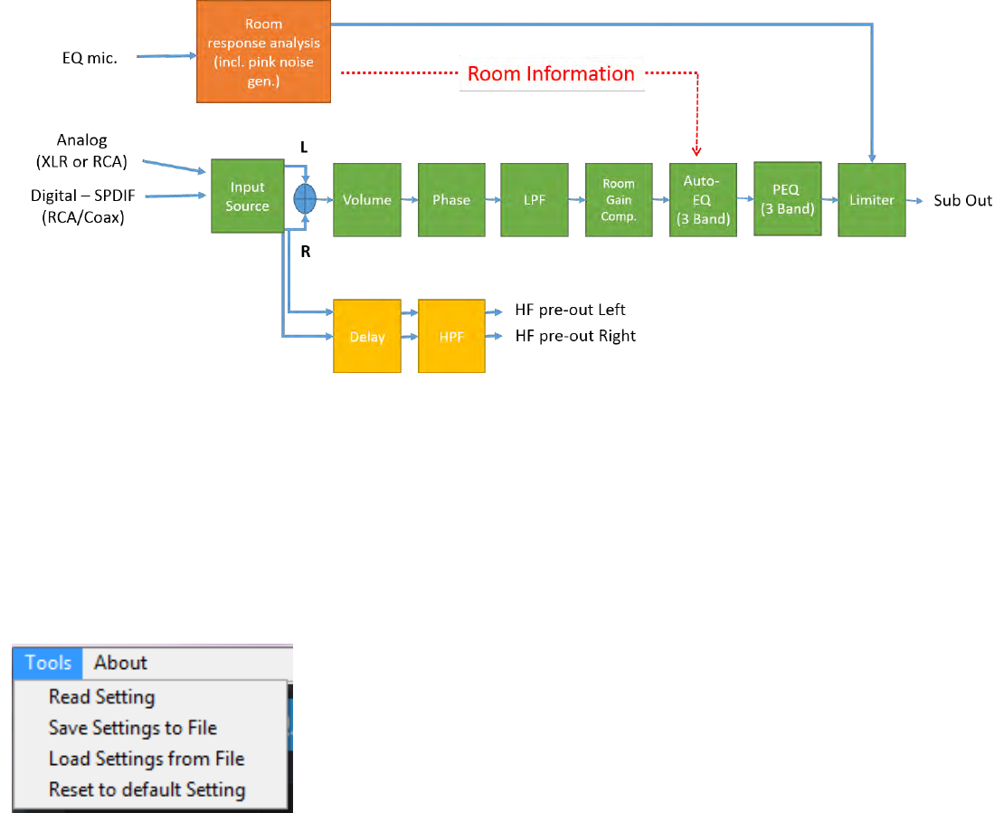
DSP processing block diagram
Controlling your subwoofer via PC GUI
The PC GUI (literally, “Personal Computer, Graphical User Interface”) is the primary mode to access
and adjust the DSP for subwoofer optimization. Follow all safe practices and contact Dayton Audio
if you require assistance.
Read Setting: Read all the setting from amp
Save Settings to File: Save current settings to PC
Load Settings from File: Load previous saved setting to AMP
Reset to default setting: Reset the AMP to factory default
See next page: For a full depiction of the primary screens and detailed identification of each of your amp GUI’s controls.
(10)
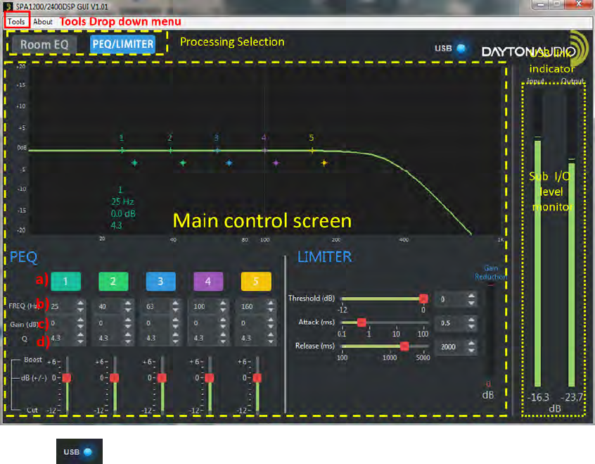
• USB Link Indicator: When communication via USB with amp is successful, the GUI’s “LED” indicator will
light blue. Otherwise, the “LED” stays dark.
• Processing Selection: Selecting any icon can effect change in near-real time (NRT) to the amp’s audio outputs.
• Main Control Screen: Control each DSP processing parameters: Threshold Power, Attack Time, Release,
along with 5 digital PEQ bands
• Sub In/Out monitor: Monitor the input signal and sub output signal levels.
• Tools Drop Down Menu: Utilities for amp DSP management, plus Wi-Fi settings.
• Note: The GUI’s graphical trace is NRT editable. Bands can be shaped by cursor or direct input and/or sliders.
Detailed tool tips (shown a-d above):
o 5 band-digital PEQ
a) Band On/Off: Bypass or enable by clicking the colorized 1 ~ 5 buttons.
b) Center Frequency (CF): Adjust Center Frequency of each EQ band, 20 ~ 200Hz. Steps: 1Hz.
c) Gain: Adjust the EQ gain (apparent volume), -12 ~ +6dB. Steps: 1dB.
d) Q (EQ width): Adjust the “Q” value, 0.4 ~ 11. Steps: 0.1Q.
o Limiter: Adjust, optimize, save, recall.
a) Threshold: Adjust the limiter “threshold power”, 0 ~ -12dB. Steps: 0.1dB
b) Attack: Adjust limiter “attack time”. This controls the allowed of time signals may be over threshold power.
Range of adjustment is 0.1 ~ 100ms (milliseconds). Steps: 0.1ms
c) Release: Adjust limiter's “release time”. When limiter is triggered, this control adjusts the time
allowed to restore full power. Adjustable range 100 ~ 5000ms. Steps: 0.1ms.

(11)
Custom algorithms apply intelligent multi-band room equalization (iEQ™)
The included 20Hz-capable iEQ microphone allows estimation of your room’s natural frequency response
characteristics and precisely applies PEQ filters to compensate for inevitable response anomalies. Plug the
microphone’s 3.5mm “male” fitting into the amp panel’s “female” jack labeled “Mic In” for this procedure.
Measurement of room acoustics requires moving your EQ mic through the room’s listening and/or viewing
“sweet spots”, typically affixed to a photo tri-pod for best acoustical results. Only three different positions are
required, as testing actually captures 12 measurements per location (automatically averaging each result).
Starting iEQ: Selecting the GUI’s button starts custom calibration test tones. After moving
your mic to three different listening locations and estimations are finished, the system screen will display the
final measured and calculated post-equalized frequency response results.
(12)
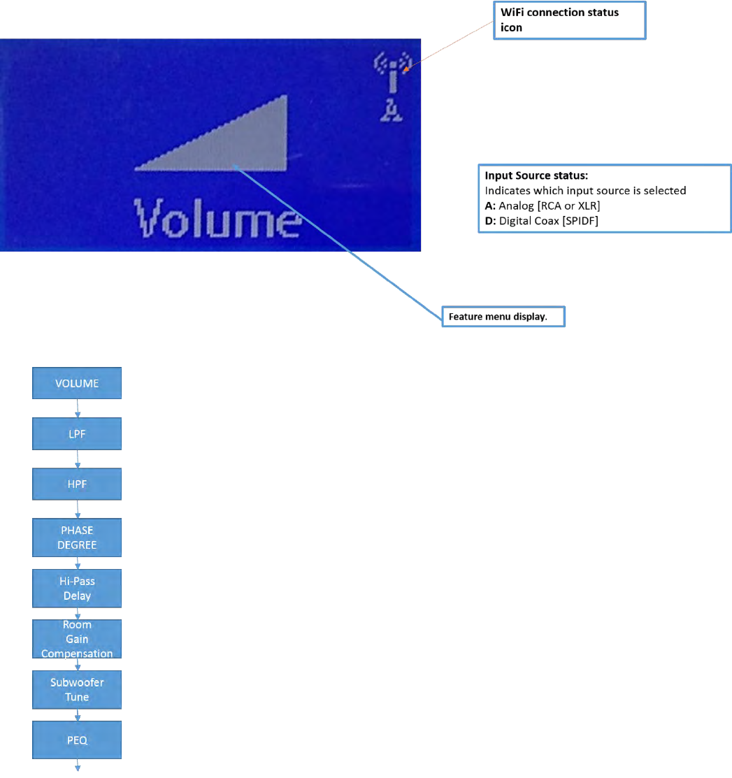
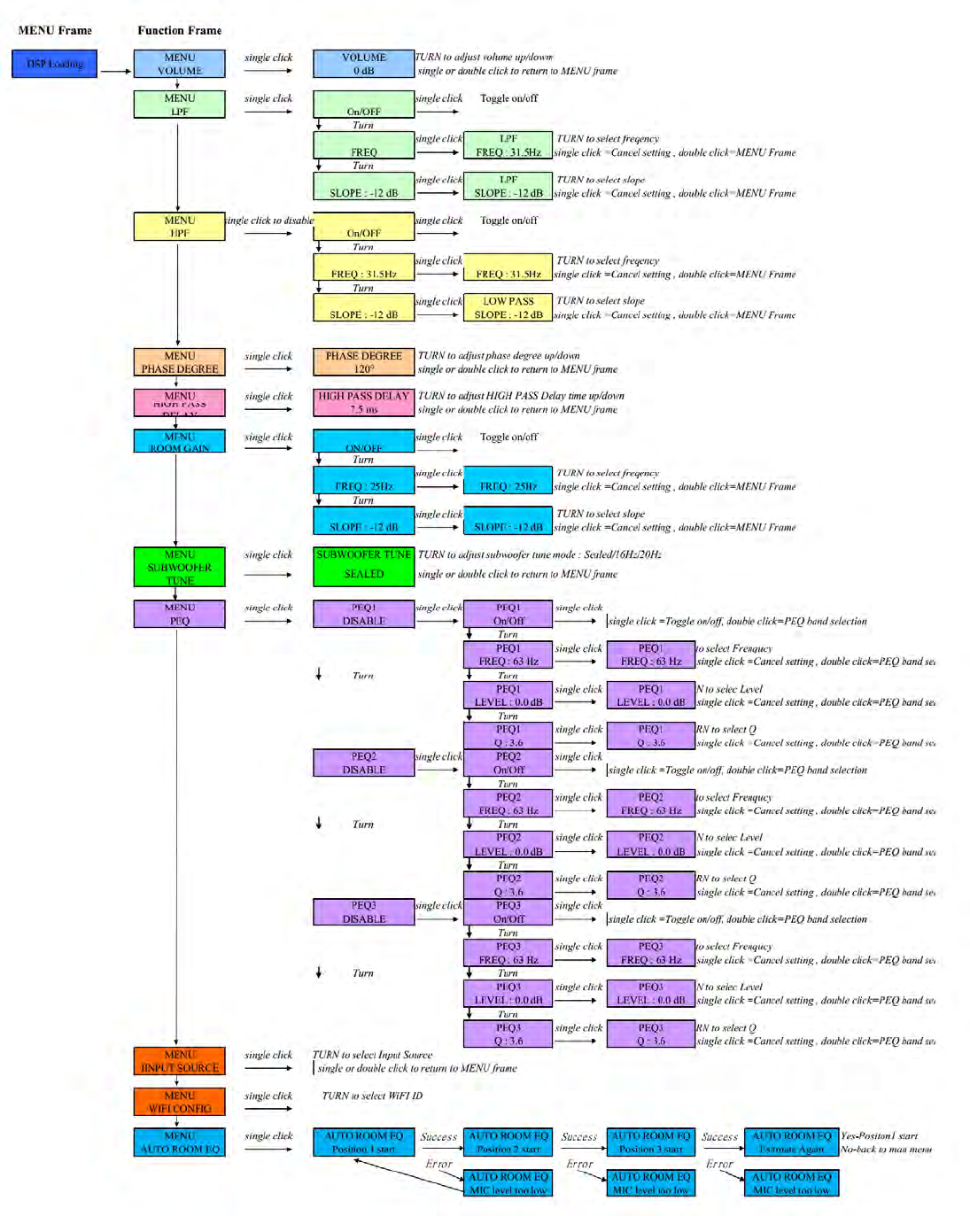
Control-Panel: Feature Menu Display
Volume, Phase, Low-Pass Filter and all other controls are also accessible via the included
rotary control.
Volume (shown above) is selected by a single click, upon which simple rotation allows 1dB
adjustment. A “double-click” brings you back to the main menu. Subsequent rotation
of the controller from the main menu navigates you through a series of setup menus.
Each of the “Function frames” at left correspond to the major feature controls on the amp.
Each feature control uses the same single/double-click navigation. Note all detailed sub-
features on the next page. Scroll around your amp and get familiar with its simple click and
double click feature rotation.
(13)
(14)
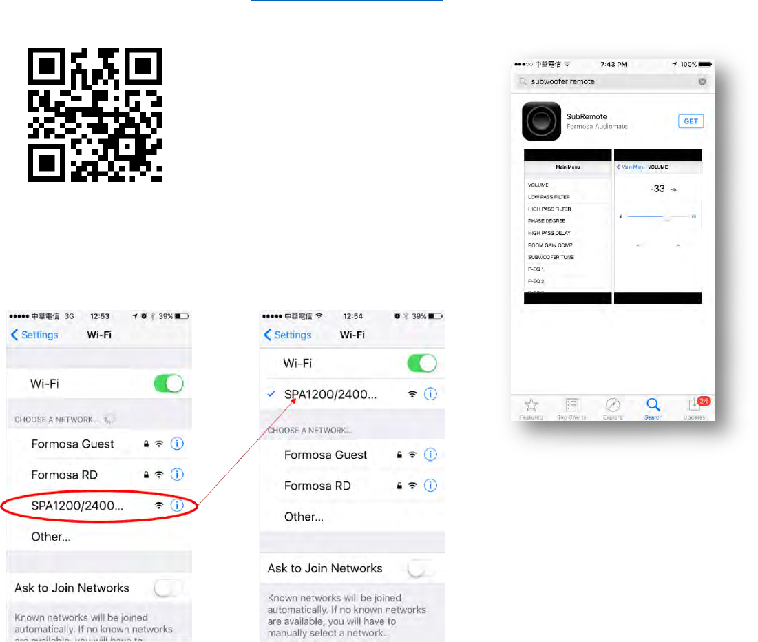
iOS Subwoofer Remote Control “App” Guide
Your SPA1200 or 2400DSP amp has its own internal Wi-Fi communication chip to allow for tuning and setup of
your sub remotely via the dedicated Dayton Audio SubRemote iPhone Control “App”.
1. Download the App from this link: https://appsto.re/tw/anF_6.i or search for “SubRemote” from Apple®
“App Store”. Alternatively, you may scan the QR code (left) for a direct link to
the App Store download page:
Discover the app (click page for
description)
2. Connect your iPhone to SPA1200 or 2400DSP sub amp from your
iPhone’s Wi-Fi setting panel:
(15)
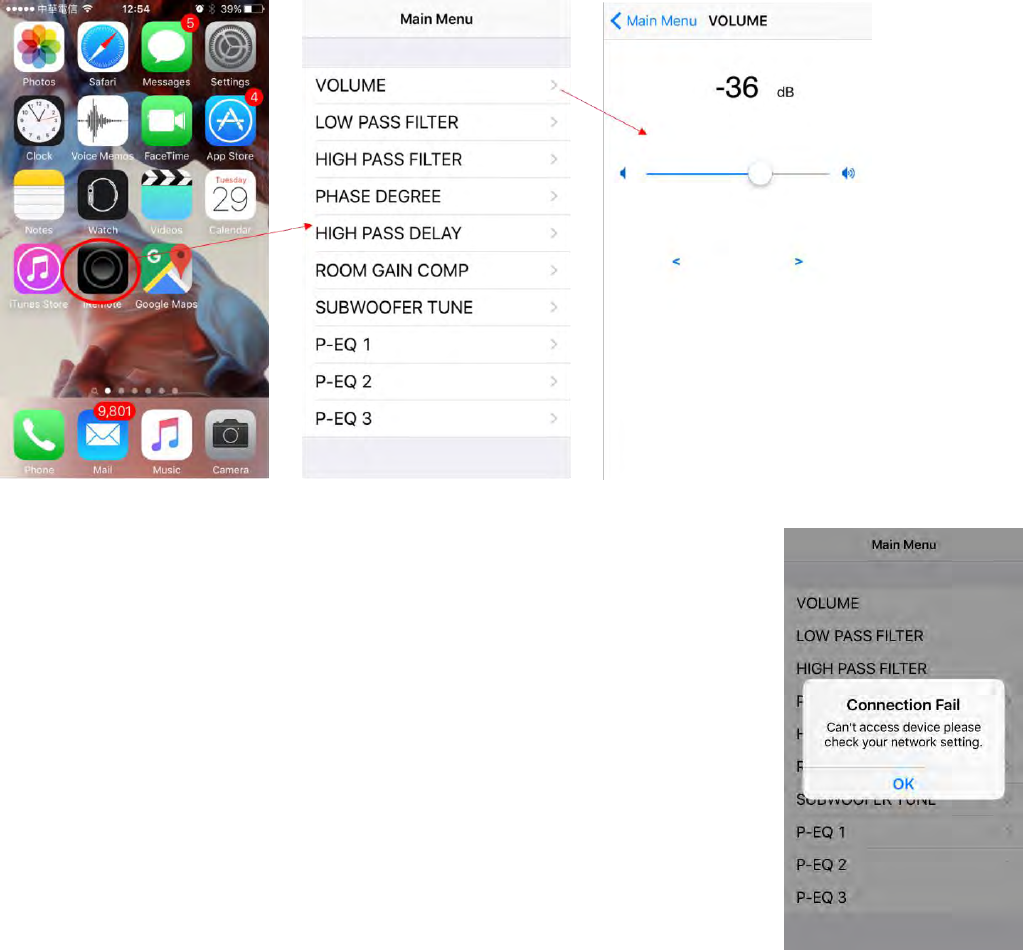
3. Once the Wi-Fi successfully links to the sub, open the app to remotely control your sub’s amp.
Note: If you have not connected your iPhone to the amp, the app will
automatically enter “demo mode”. The demo mode is just a demonstration of
each function. Optimally “smooth” operation is not functional in demo
mode, but each screen can be navigated for familiarization. Only when
connected to via Wi-Fi can your sub’s amp be manipulated however.
(16)
Firmware Update Guide:
Bug fixes or feature improvements may be introduced via Dayton Audio “firmware” updates. Use this
procedure if such an update is provided to all amp owners:
1. Turn off the amp from the main power switch (next to power cord inlet).
2. Press and hold the control-panel’s feature rotary knob, and then turn on the amp. The device will
immediately enter the firmware upgrade mode. When the device successfully enters this mode, the
“Standby” (STB) LED will begin blinking.
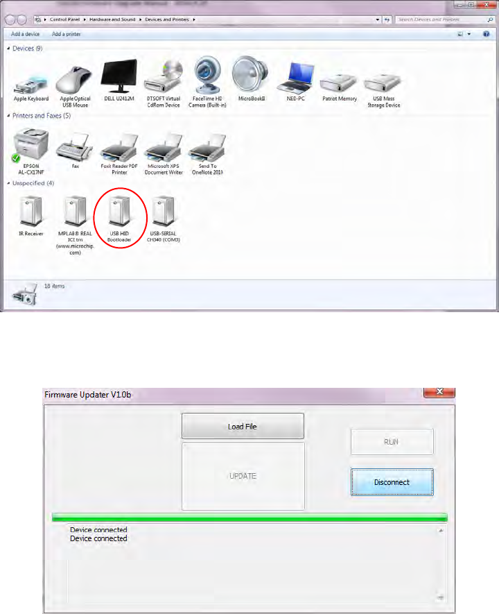
3. Connect your PC’s USB cable to the USB jack on amp’s back panel. When the connection is successful,
in Windows 7® or later “Device and Printers” will allow you see a new “USB HID Bootloader” device.
4. Open the “Firmware Updater” (application provided on your Dayton Audio amp software CD), and press
“Connect”. When successfully connected, the below panel will appear:
(17)
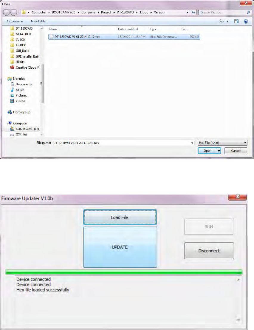
5. Load the updated firmware file from your saved location and select which new version by clicking the
above “Load File” button:
6. When the firmware update is loaded, the below panel and green “progress bar” will show:
(18)
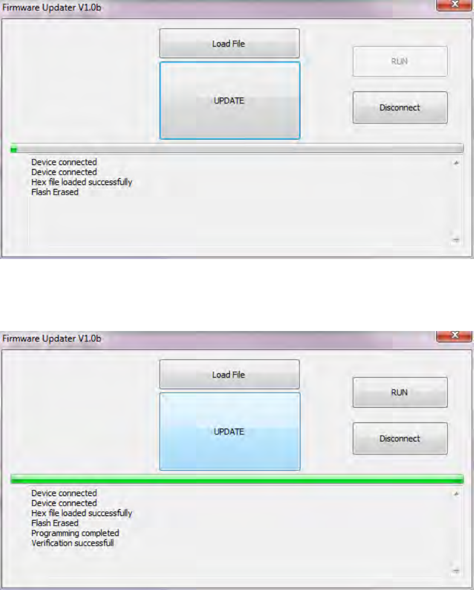
7. Press “UPDATE” and the firmware will begin installation:
8. After installation is complete the panel shows:
(19)
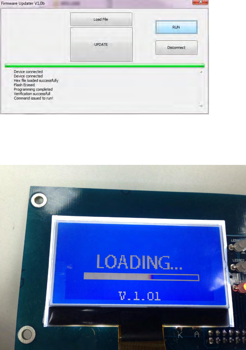
9. Press “RUN” or cycle power on your amp and the device will now run the new firmware version!
10. To validate your firmware was successfully updated you can note a new operating system version
number “V.X.0X” on amp boot-up.

(20)