Patriot One Technologies CMR PATSCAN CMR User Manual Installation Guide
Patriot One Technologies Inc. PATSCAN CMR Installation Guide
UserManual.wiki
>
Patriot One Technologies
>
CMR User Manual
>
Installation Guide
Contents
1.
Installation Instructions
2.
Installation Guide
3.
Operational Manual
Installation Guide
Navigation menu
Upload a User Manual
Namespaces
Wiki Guide
HTML
PDF
Info
Views
User Manual
Discussion / Help
Navigation

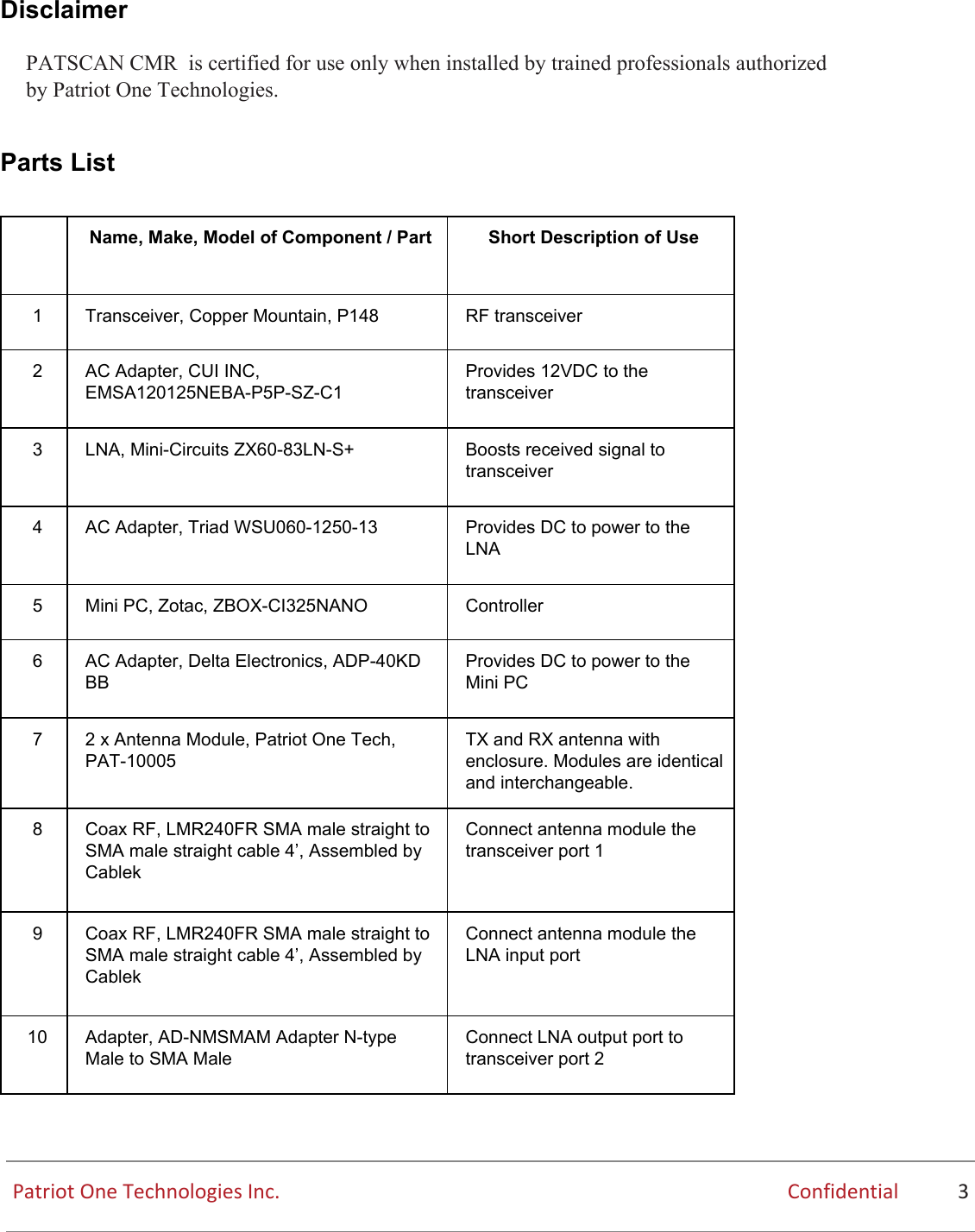
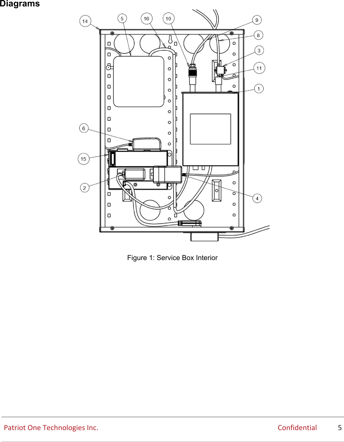
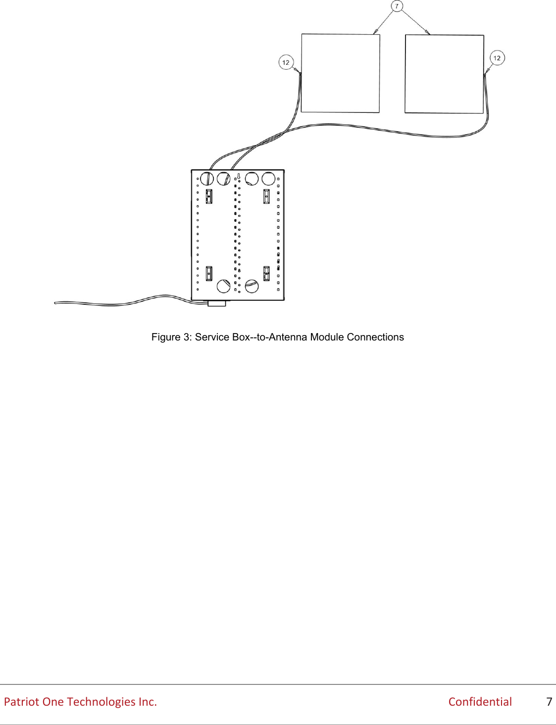
![11 Adapter, AD-NMSMAF Adapter N-type Male to SMA Female Adapts transceiver port 1 to N to SMA 12 Adapter, AD-SMAMSMAF-90 Adapter SMA Male to SMA Female 90º Right Angle Adapts antenna Module port 1 13 Adapter, AD-SMAMSMAF-90 Adapter SMA Male to SMA Female 90º Right Angle Adapts antenna Module port 2 14 Service box, Legrand On-Q EN2050 Enclosure for transceiver, Mini PC and LNA. 15 Power bar, Legrand On-Q, AC1031 Power bar for items inside the service box 16 USB cable Connects the transceiver to the Mini PC Customer-Provided Parts The customer must provide: ● Network cable of sufficient length to connect Mini PC to network will be provided by customer. ● Access to a PC with [need specs] Patriot One Technologies Inc. Confidential 4](https://usermanual.wiki/Patriot-One-Technologies/CMR.Installation-Guide/User-Guide-3551729-Page-5.png)