Patriot One Technologies CMR PATSCAN CMR User Manual Installation Guide
Patriot One Technologies Inc. PATSCAN CMR Installation Guide
Contents
- 1. Installation Instructions
- 2. Installation Guide
- 3. Operational Manual
Installation Guide

PATSCAN CMR
Technical Installation Guide
v.1.03 - DRAFT
07/27/2017

© 2017 PatriotOne Technologies
All rights reserved.
No part of this publication may be reproduced, distributed, or transmitted in any form
or by any means, including photocopying, recording, or other electronic or mechanical
methods, without the prior written permission of the publisher, except for training
purposes.
PatriotOne Technologies Inc.
Unit 302 – 3380 South Service Rd
Burlington, Ontario L7N 3J5 Canada
+1 (888) 728-1832
info@patriot1tech.com
Patriot One Technologies Inc. Confidential 1


Disclaimer
PATSCAN CMR is certified for use only when installed by trained professionals authorized
by Patriot One Technologies.
Parts List
Name, Make, Model of Component / Part
Short Description of Use
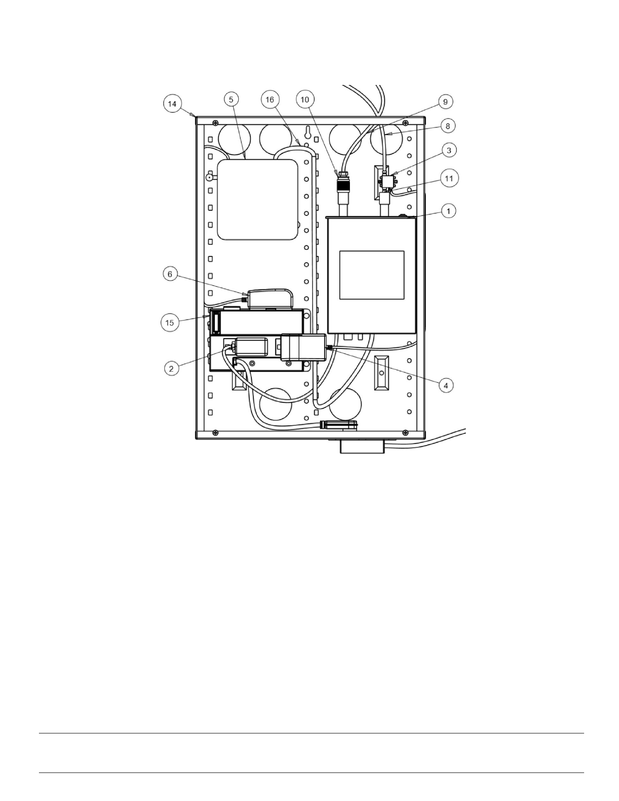
1
Transceiver, Copper Mountain, P148
RF transceiver
2
AC Adapter, CUI INC,
EMSA120125NEBA-P5P-SZ-C1
Provides 12VDC to the
transceiver
3
LNA, Mini-Circuits ZX60-83LN-S+
Boosts received signal to
transceiver
4
AC Adapter, Triad WSU060-1250-13
Provides DC to power to the
LNA
5
Mini PC, Zotac, ZBOX-CI325NANO
Controller
6
AC Adapter, Delta Electronics, ADP-40KD
BB
Provides DC to power to the
Mini PC
7
2 x Antenna Module, Patriot One Tech,
PAT-10005
TX and RX antenna with
enclosure. Modules are identical
and interchangeable.
8
Coax RF, LMR240FR SMA male straight to
SMA male straight cable 4’, Assembled by
Cablek
Connect antenna module the
transceiver port 1
9
Coax RF, LMR240FR SMA male straight to
SMA male straight cable 4’, Assembled by
Cablek
Connect antenna module the
LNA input port
10
Adapter, AD-NMSMAM Adapter N-type
Male to SMA Male
Connect LNA output port to
transceiver port 2
Patriot One Technologies Inc. Confidential 3

11
Adapter, AD-NMSMAF Adapter N-type Male
to SMA Female
Adapts transceiver port 1 to N to
SMA
12
Adapter, AD-SMAMSMAF-90 Adapter SMA
Male to SMA Female 90º Right Angle
Adapts antenna Module port 1
13
Adapter, AD-SMAMSMAF-90 Adapter SMA
Male to SMA Female 90º Right Angle
Adapts antenna Module port 2
14
Service box, Legrand On-Q EN2050
Enclosure for transceiver, Mini
PC and LNA.
15
Power bar, Legrand On-Q, AC1031
Power bar for items inside the
service box
16
USB cable
Connects the transceiver to the
Mini PC
Customer-Provided Parts
The customer must provide:
● Network cable of sufficient length to connect Mini PC to network will be provided by customer.
● Access to a PC with [need specs]
Patriot One Technologies Inc. Confidential 4
Diagrams
Figure 1: Service Box Interior
Patriot One Technologies Inc. Confidential 5
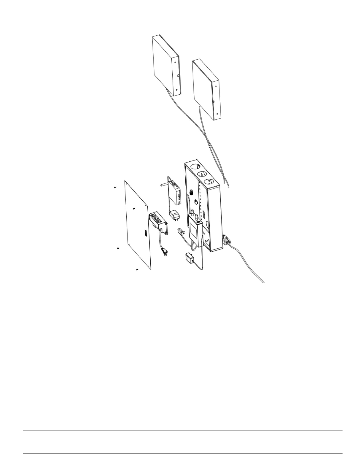
Figure 2: System Exploded View
Patriot One Technologies Inc. Confidential 6
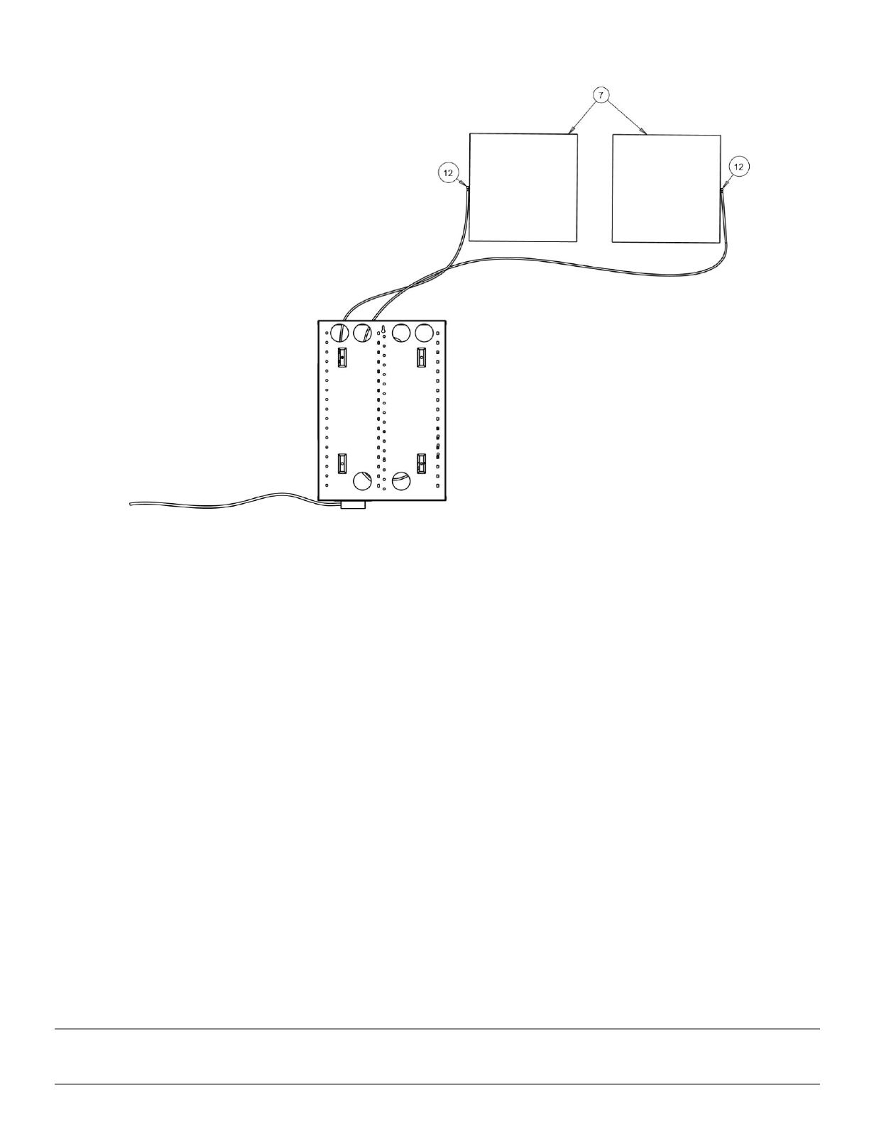
Figure 3: Service Box--to-Antenna Module Connections
Patriot One Technologies Inc. Confidential 7
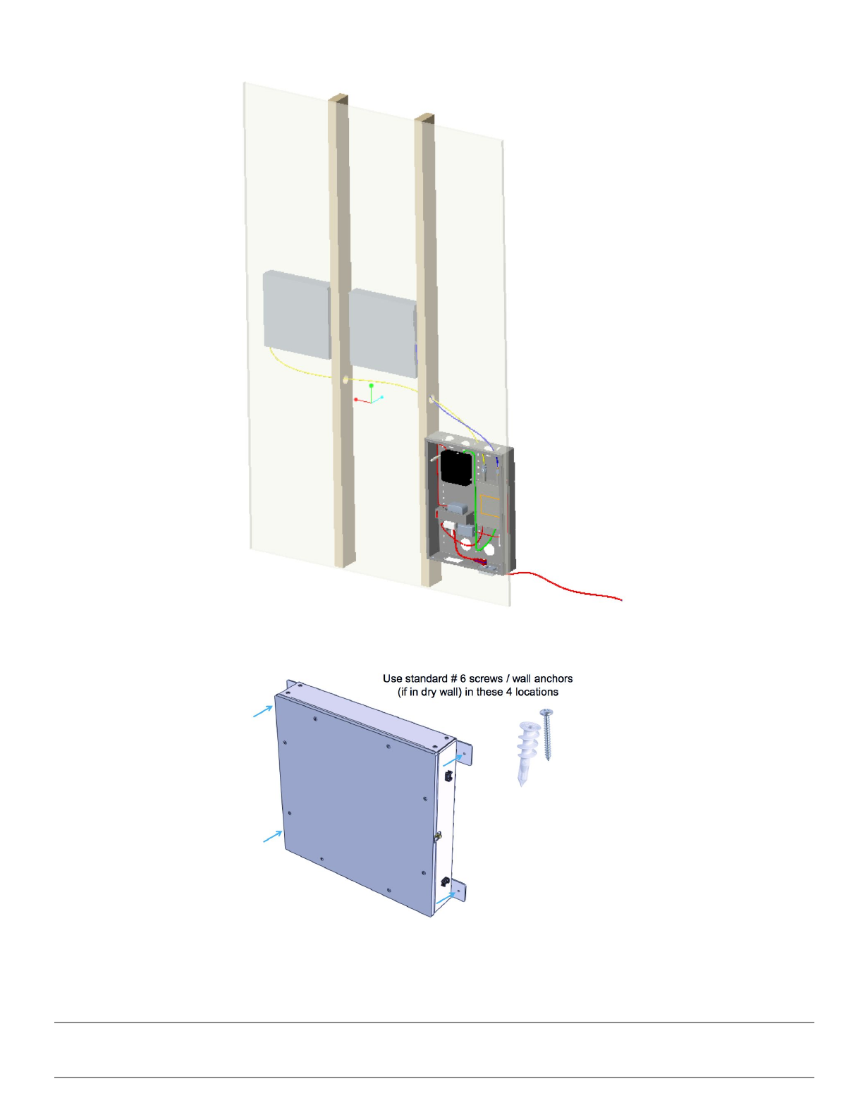
Figure 4: Example Installation in Wall
Figure 5: Antenna Module Mounting
Patriot One Technologies Inc. Confidential 8
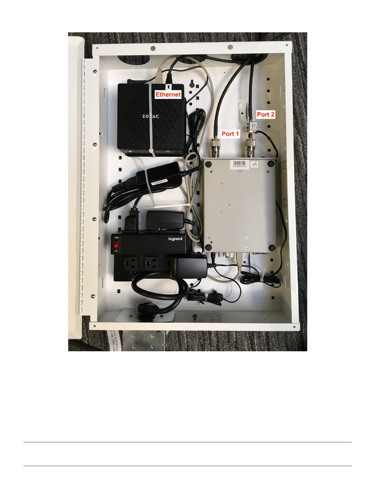
Figure 6: Service Box Cable Connections
Procedures
Planning Stage
Determine where the system will be installed. The wall that will contain the antenna modules and service box needs to
Patriot One Technologies Inc. Confidential 9

allow for no more than 4 feet between each antenna module and the service box. The antenna module and service box are
sized to fit between wall studs.
Hardware Installation
1. Open the shipping box and carefully remove the components
○Two Antenna Modules (part 7)
○One White Enclosure (part 14)
○Two SMA cables (parts 8 and 9)
2. Install the two antenna modules within the wall
○Each module includes mounting plates with screw holes. See figure 5.
○Ensure antenna module with cable reaches service box connection.
3. Install service box
○Follow Legrand EN2050 Installation Guide
○Install standard electrical outlet as per applicable codes. Shown in EN2050 Installation Guide
4. Connect SMA cables to outer edge of each antenna module as shown in figure 3.
5. Run the cables through the open port on the top of the service box.
6. Attach cable 1 to “Port 1” shown in figure 6.
7. Attached cable 2 to “Port 2” shown in figure 6.
8. Run ethernet cable from network into the enclosure through open port
9. Connect ethernet cable to the “Ethernet” port shown in figure 6
10. Plug in the power bar to the installed electrical connection
11. Turn on the power module
12. Verify the transceiver power switch is ON
13. Press power button on PC
14. Close the enclosure and lock it
Patriot One Technologies Inc. Confidential 10