Paxton Access 162739 OEM Plastic Reader Keypad / Mace Security Standalone Plastic Reader & Keypad User Manual INSTRUCTION OEM plastic reader keypad
Paxton Access Ltd OEM Plastic Reader Keypad / Mace Security Standalone Plastic Reader & Keypad INSTRUCTION OEM plastic reader keypad
Contents
- 1. Paxton User Manual
- 2. Mace Security User Manual
Paxton User Manual
Page 1
Ins-30012-US OEM plastic reader keypad
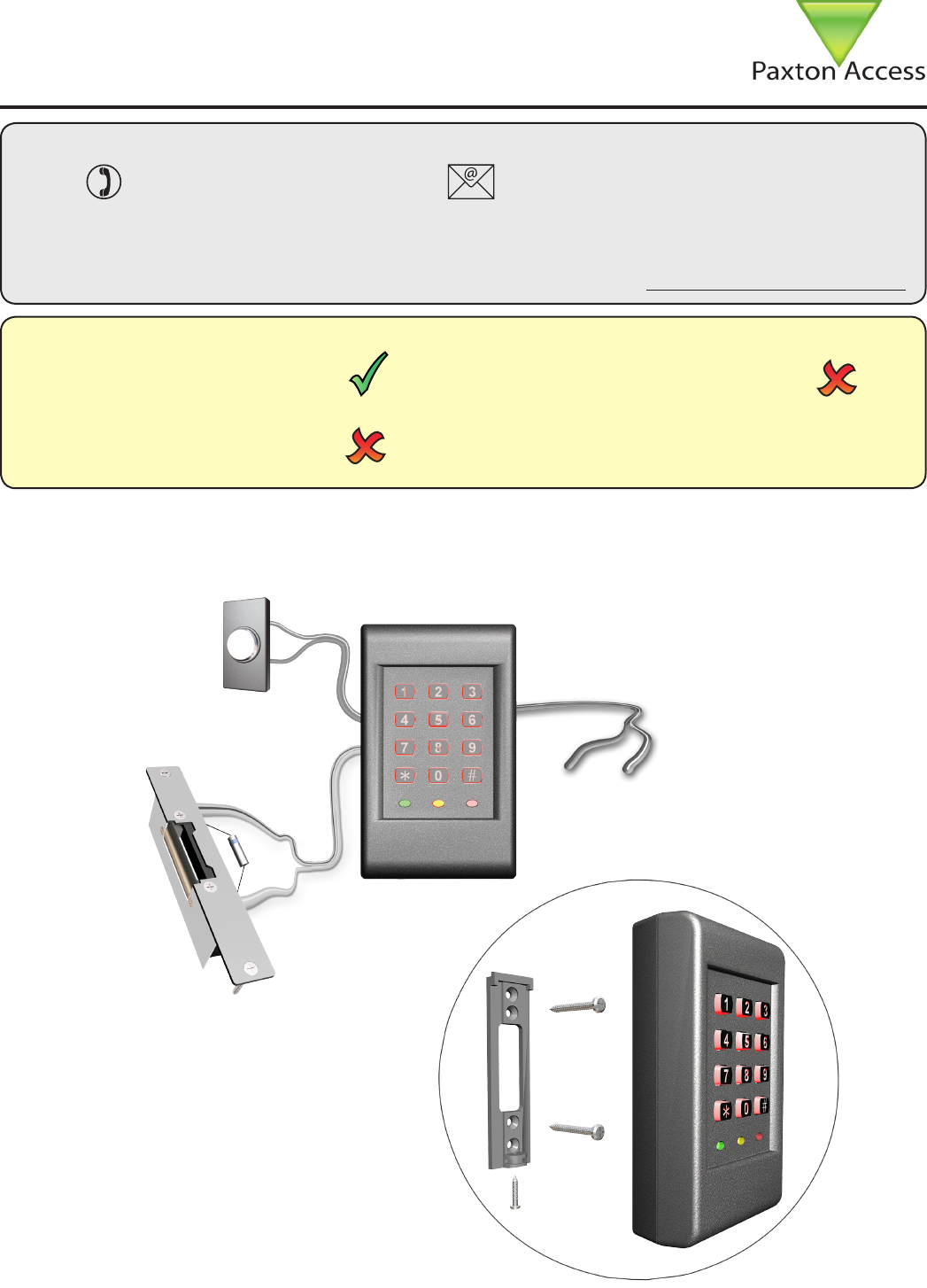
Suitability
Fitting
Exit button
(push to make)
0V
9-15V DC
12V DC release current rating
must be less than 1A.
*
(fuse rating 1A)
* The diode current rating must
be equal to or greater than the
current in the release
09/23/2009
Security sensitive doors
Wet environments Mounted on metal surface
Readers mounted together
between readers
12 inches
User cards are NOT supplied with this unit. Please supply your own user cards.
Grey
Black
White
+12V DC
Technical Support
Technical help is available: Monday - Friday from 12:00 AM - 5:00 PM (PST)
Saturday from 1:00 AM - 5:00 AM (PST)
1.800.672.PAXT support@paxton-access.com
Documentation on all Paxton Access products can be found on our web site - http://www.paxton-access.com/
+
-

Page 2
FCC Compliance
This device complies with Part 15 of the FCC Rules. Operation is subject to the following two conditions:
(1) this device may not cause harmful interference, and (2) this device must accept any interference
received, including interference that may cause undesired operation. Changes or modications not
expressly approved by the party responsible for compliance could void the user’s authority to operate the
equipment.
Please read the following notes before installing
Electrical shock from voltages used in this system can cause injury or death. Prior to making
any electrical connections, or performing maintenance and repair, ensure power is removed.
Mains electrical connections should be made only by qualied personel in accordance with local
regulation. Safety goggles should be worn while using power tools.
Step 1: Carefully mark out the mounting holes for the keypad and the hole of the cable feed.
Step 2: Drill the marked holes for the mounting points and the cable feed. When drilling the holes, ensure
that you are aware of any hidden cables or pipes. Once the holes have been drilled, t the supplied wall
plugs and feed the cable through the cable feed hole before securing the reader to the wall using the
screws supplied.
Step 3: Fit the keypad to the mounting plate and secure using the screw provided.
Fitting the keypad
Page 3
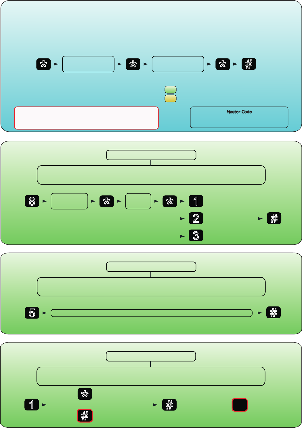
The factory User Code is now set to 7890
Enter 6 digit
Master Code
Enter 6 digit
Master Code
* * * #
PressPress Press Press
Setting The Master Code
The first time the keypad is turned on the RED and GREEN LEDs flash alternately.
This indicates a 6 digit Master Code must now be entered.
»The Master Code allows access to the Programming Menu.
To set the Master Code, do the following:
see
see
for programming options
for adding proximity tokens
to exit
programming
mode
NOTE
The Master Code must not contain a User Code (for example
123456 as a Master Code and 2345 as a User Code would cause
the door to open before the Master Code had been entered.
Enter code
4-8 digits
re-enter
code
* *
#
Press Press
Press
Changing the entry code
to exit
programming
mode
Enter 6 digit Master Code
The RED and GREEN LEDs flash simultaneously indicating reader is in
Programming Mode
Press and hold
for 3 seconds
8 1
2
3
= Normal
= Master
= Delete }
Enter 2 digits from 01 to 60 (default door open time is 07 seconds #
Press
Changing the door open time
to exit
programming
mode
Enter 6 digit Master Code
The RED and GREEN LEDs flash simultaneously indicating reader is in
Programming Mode
Press and hold
for 3 seconds
5
#
Press
Changing the lock type
to exit
programming
mode
Enter 6 digit Master Code
The RED and GREEN LEDs flash simultaneously indicating reader is in
Programming Mode
Press and hold
for 3 seconds
1*
#
= Fail open
= Fail locked
{
press }= default
Page 4
#
Press
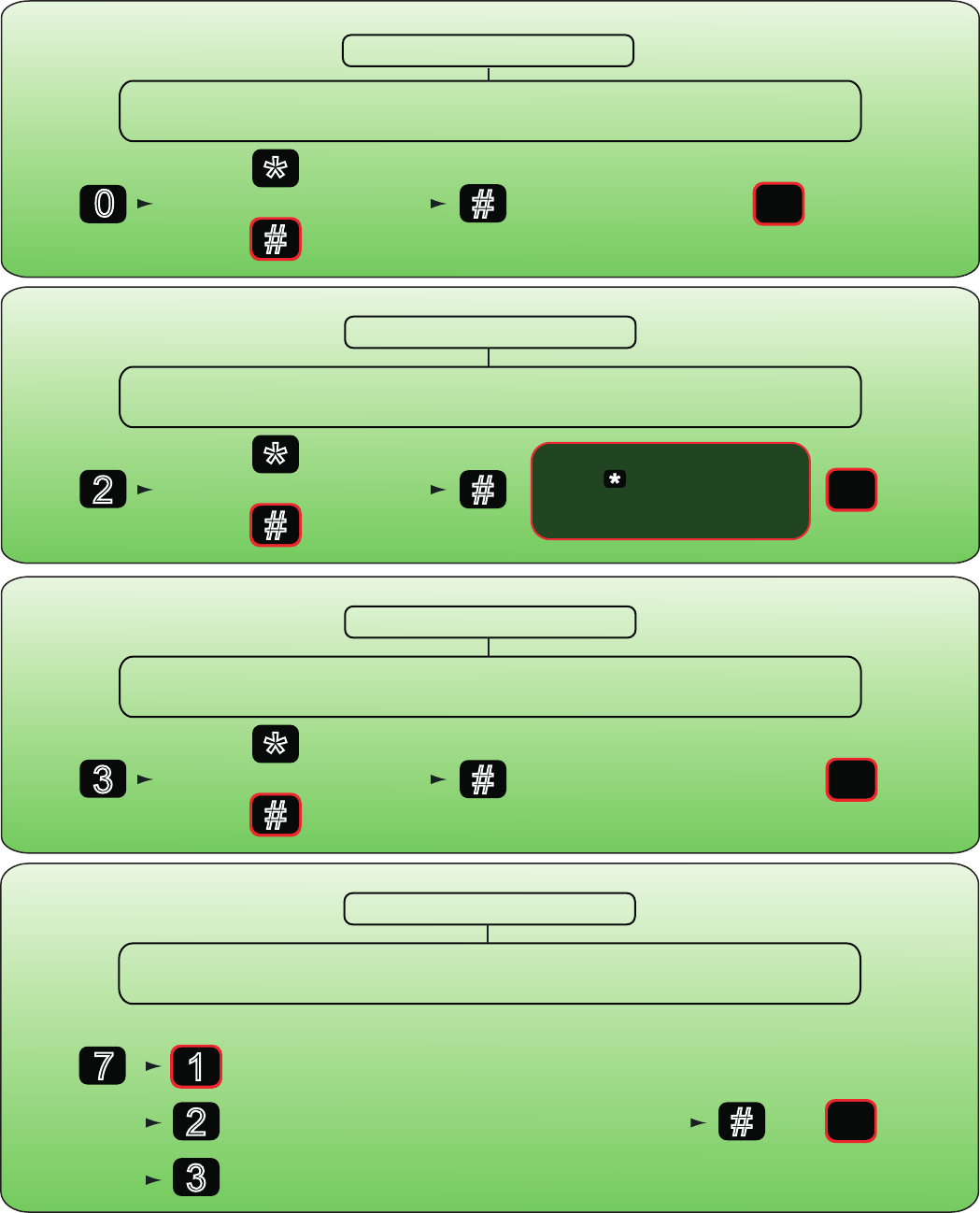
Changing the keypad backlight
to exit
programming
mode
Enter 6 digit Master Code
The RED and GREEN LEDs flash simultaneously indicating reader is in
Programming Mode
Press and hold
for 3 seconds *
#
= On
= Off
{
press }= default
0
#
Press
Setting multiple entry codes
(maximum = 120)
to exit
programming
mode
Enter 6 digit Master Code
The RED and GREEN LEDs flash simultaneously indicating reader is in
Programming Mode
Press and hold
for 3 seconds *
#
= On
= Off
{
press }= default
2
When in Multi User Code mode
the (star) key must be
pressed after the code is
entered for the door to release.
#
Press
Setting the keypad sounder
to exit
programming
mode
Enter 6 digit Master Code
The RED and GREEN LEDs flash simultaneously indicating reader is in
Programming Mode
Press and hold
for 3 seconds *
#
= Off
= On
{
press }= default
3
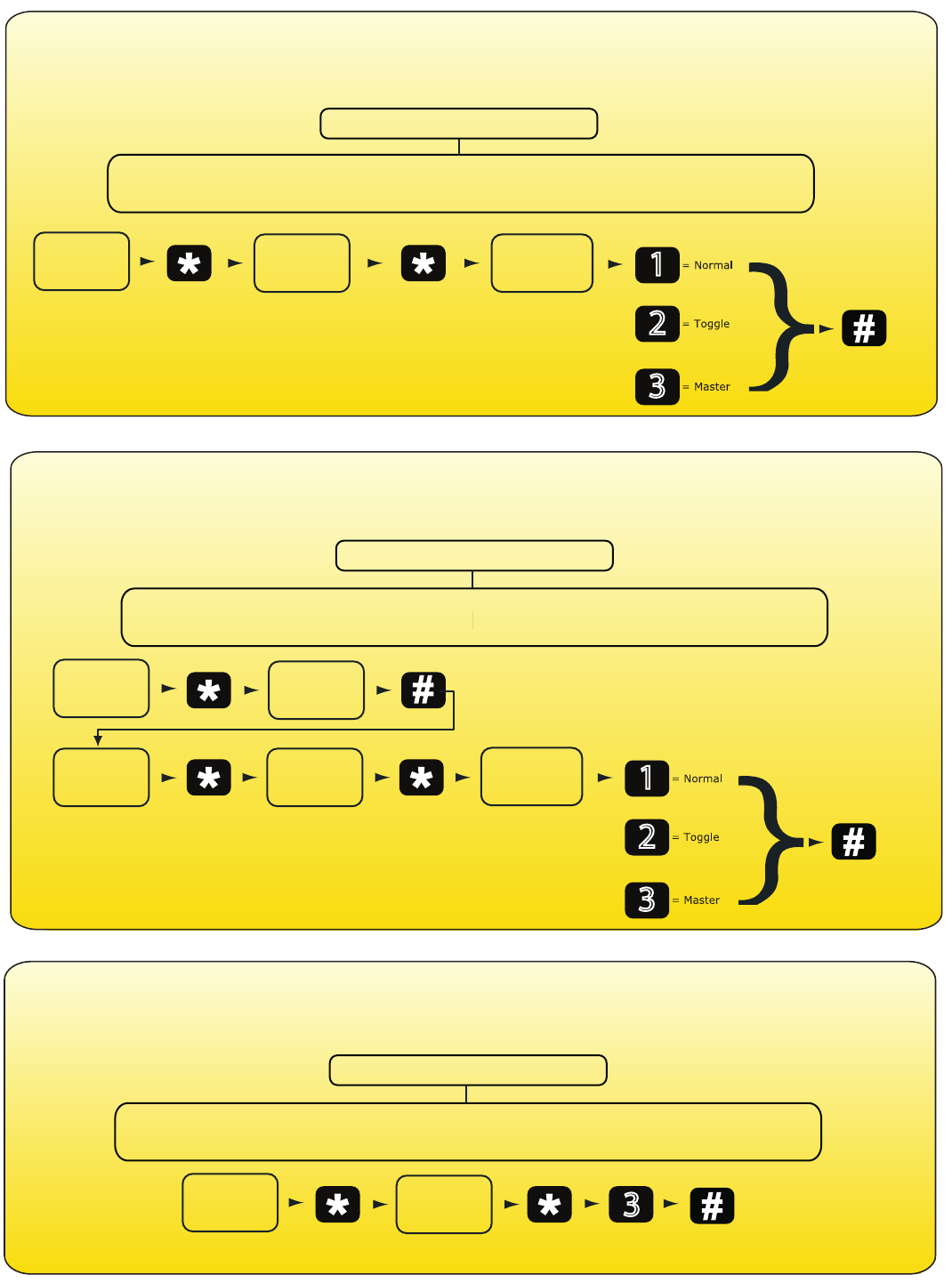
Setting the exit button mode
Enter 6 digit Master Code
The RED and GREEN LEDs flash simultaneously indicating reader is in
Programming Mode
Press and hold
for 3 seconds
= default
7
2
3
= Normal (press once to open door)
= Toggle (press once to open, press again to close)
= Disabled (exit button does not open the door)
#
Press
to exit
programming
mode
}
1
Page 5
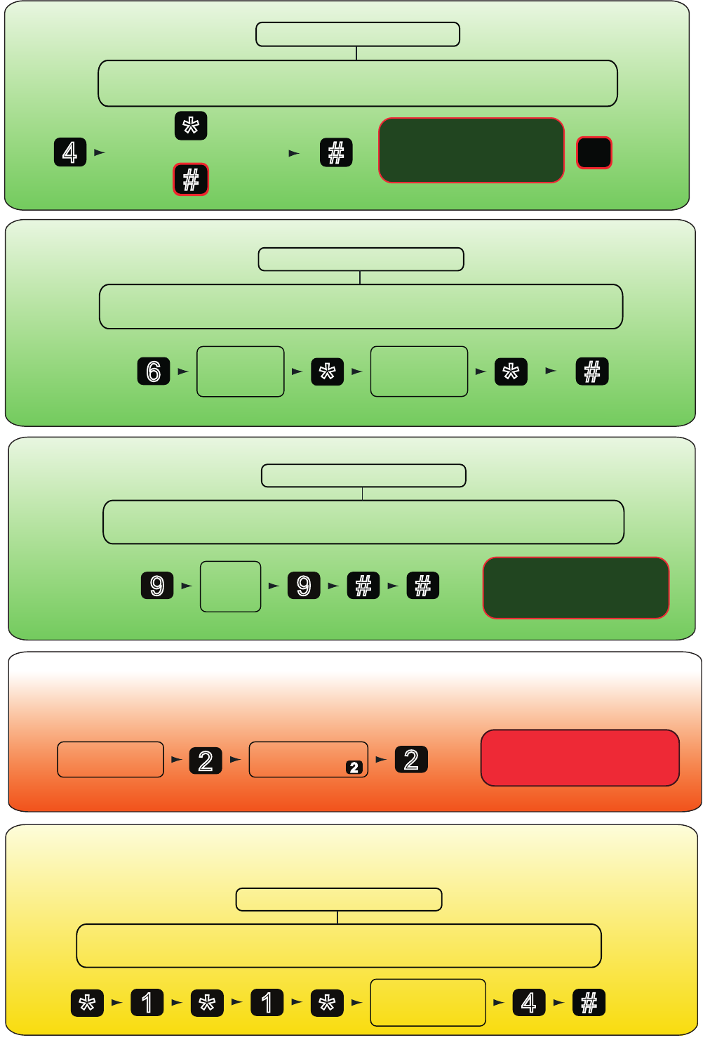
Remove power
to the keypad
Resetting the keypad
(INCLUDING the Master code)
Press and
hold
Hold for 3
seconds
once power is
applied
2
Re-apply power,
still holding 2
Once reset, the keypad will need
a new Master code set, as per the
programming section
2
Enter new
6 digit
Master code
Re-enter new
6 digit
Master code
* *
Press Press
Changing the Master code
Enter 6 digit Master Code
The RED and GREEN LEDs flash simultaneously indicating reader is in
Programming Mode
Press and hold
for 3 seconds
6#
Press
to exit
programming
mode
Enter
Master
code
Press
Resetting the keypad
(EXCEPT the master code)
Enter 6 digit Master Code
The RED and GREEN LEDs flash simultaneously indicating reader is in
Programming Mode
Press and hold
for 3 seconds
#
Press
to exit
programming
mode
9
Press and hold
for 3 seconds
9#
Once completed, all settings
except the Master code will be
restored to their default setting
Present
proximity token
to the keypad
Creating a master token
Enter 6 digit Master Code
The RED and GREEN LEDs flash simultaneously indicating reader is in
Programming Mode
Press and hold
for 3 seconds
*1*1*4#
Press
exits
programming
mode
PressPressPressPressPress
The first token must be registered as a Master token.
This will be required for the addition of other proximity tokens and also the proximity programming functions.
#
Press
Setting the keypad for
additional security
to exit
programming
mode
Enter 6 digit Master Code
The RED and GREEN LEDs flash simultaneously indicating reader is in
Programming Mode
Press and hold
for 3 seconds *
#
= On
= Off
{
press }= default
4
When enabled, the keypad will
deactivate for 60 seconds if
there are 20 consecutive
incorrect numbers entered
Page 6
Adding proximity tokens
Present the Master Token
The RED and GREEN LEDs flash simultaneously indicating reader is in
Programming Mode
Up to 2000 proximity tokens can be added to the keypad. Each token is allocated to a memory slot on the keypad.
A note will need to be made of the memory slot a token is allocated to, a handy table is included in these instructions
for this purpose. To add a proximity token to the reader do the following:
Press
to exit
programming
mode
Press Press
Re-enter
memory
slot number
Present proximity
token to
the keypad
Enter
memory
slot number
Press
1
or
2
or
3
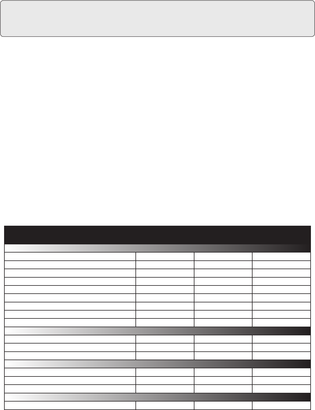
Adding proximity plus PIN tokens
For additional security, you may wish a user to enter a PIN (personal identification number) as well as present a proximity
token, in order to open the door. To configure a token to require PIN entry as well, do the following:
Present the Master Token
The RED and GREEN LEDs flash simultaneously indicating reader is in
Programming Mode
Press
to exit
programming
mode
Press Press
Re-enter
memory
slot number
Press Press
Re-enter
PIN
Present proximity
token to
the keypad
Enter
memory
slot number
Enter PIN
Press
or
or
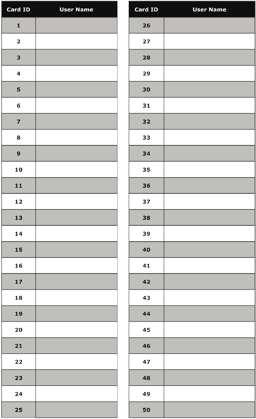
Barring proximity tokens
If a proximity token has been lost, or you no longer wish the user to gain entry, the proximity token can easily be removed
from the system. To remove a user token, do the following:
Present the Master Token
The RED and GREEN LEDs flash simultaneously indicating reader is in
Programming Mode
Press
to exit
programming
mode
Press Press Press
Re-enter
memory
slot number
Enter
memory
slot number
Page 7
1 2,000
4 digits 8 digits
4 digits
1 sec 60 sec
9V DC 15V DC
30 mA
1 A
-20°C (-4°F) 55°C (131°F)
IP67
2 3/4 inch 4 1/2 inch 1 1/4 inch
Voltage
Specifications
Operating temperature
Electrical
Environment
Dimensions
Min Max
Width Height Depth
Current
Outdoor Use
Features
Door open time
Silent operation
Can be used with fail OPEN locks
Can be used with fail CLOSED locks
Exit button input
Waterproof
Number of Users
Switchable current
Min
Min
Max
Max
Yes
Yes
Yes
Yes
Here is the list of topics about this product that receive the most technical support inquiries.
We list them here to help you speed up the installation and trouble shooting process.
Technical Help
1. I have connected the keypad correctly. Why doesn’t it open when I enter my code?
Q- Check that there is power to the keypad by setting the keypad backlight to ON, and listening for keypad beeps.
Q If not, check the power supply.
Q- Check that the green light ashes when the correct code is entered. If not, the code has not been entered
Q correctly, or may have been incorrectly programmed initially.
Q- Check that the lock is capable of operating with a 12V DC power supply.
Q- Check the connections.
2. When I enter my code, I hear a click and the unit resets. Why does the release not unlock?
QThis can be caused by incorrect wiring of the output wires or the diode. If a DC lock is used, check that a diode
Qis connected across the lock so that the band is nearest the +V connection. This fault may blow a fuse in the
Qpower supply - check for above before replacing the fuse.
3. The door is always unlocked. Why, and how do I get it to lock again?
QIf the green light on the keypad is on constantly, check the type of lock that is tted. If it is a fail open type,
Qit requires power to be applied to its terminals to keep it locked. A fail locked type (more common) requires power
Qonly when it is to be kept open. Refer to the programming instructions to set the keypad for the correct lock type.
QIf this is set correctly, check all wiring for shorts or bad connections. Check that a diode is tted to the DC lock
Qand is connected correctly. If not, the keypad may be damaged and will have to be replaced. Damaged relay
Qcontacts are not covered by product warranty.
QIf the green light on the keypad is ashing, switch off the power. Wait for 10 seconds and switch the power
Qon again. If the door is locked and the green light is on constantly again, it is likely that the user code is set to
Qoperate in toggle mode. If you do not want toggle codes, reset the keypad and enter new codes accordingly.
QIf on re-applying power, the keypad’s green light is still ashing, and the door is still open, check the exit button
Q(grey) wires. These could be connected to an exit button of the incorrect type, or shorted by faulty wiring, or the
Qexit button operation could be set incorrectly. Rectify and re-test.
Code length
PIN length
Cable length
Backlight Yes
3 yards
Page 8