Paxton Access 337937 Net2 Entry - VR Panel, surface mount User Manual manual
Paxton Access Ltd Net2 Entry - VR Panel, surface mount manual
manual
Page 1
05/10/2013
Ins-30208-US Net2 Entry - Vandal Resistant Panel
Technical Support
Technical help is available: Monday - Friday from 02:00 AM - 8:00 PM (EST)
1.800.672.7298 supportUS@paxton-access.com
Documentation on all Paxton products can be found on our web site - http://www.paxton-access.com/
Paxton
The Net2 Entry panel is a robust door entry panel incorporating both door entry and access control functions. It is
powered using power over Ethernet (PoE) and communicates with the other elements of the system using IPv6,
providing 'plug and play' installation. Each panel is associated with a Net2 Entry control unit which is the interface to
the door hardware.
Description of product
The panel is equipped with a keypad and a proximity token reader. A resident can use either the keypad or a token to
gain entry. Installers gain access to the menu options using an engineer code or an engineer token.
Net2 software is used to administer the access control functions. It must be v4.25 or a later version.
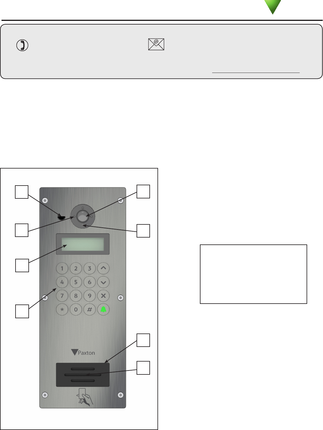
1. Speaker
2. Proximity reader
3. Keypad
4. LCD display
5. IR LEDS for night time operation
6. Microphone
7. Color camera
8. Light sensor
2
4
5
1
67
8
3
Page 2
Decide how the units are to be connected. You can either run your own wired network or share the buildings
existing data network. If using the owners network, the system uses IPv6 protocol and PoE (Power over Ethernet)
so the network must support this switch type.
Installation
Mounting
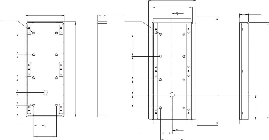
The unit is supplied with the surface mount backbox. A ush mount backbox is also available (PN:337-857).
Screws and wall plugs are provided in the tting kit.
SURFACE
BACKBOX
FLUSH
BACKBOX
A single hole must be drilled for the single data/power connection. Electrical power is supplied via the data cable (PoE)
from the Net2 Entry controller.
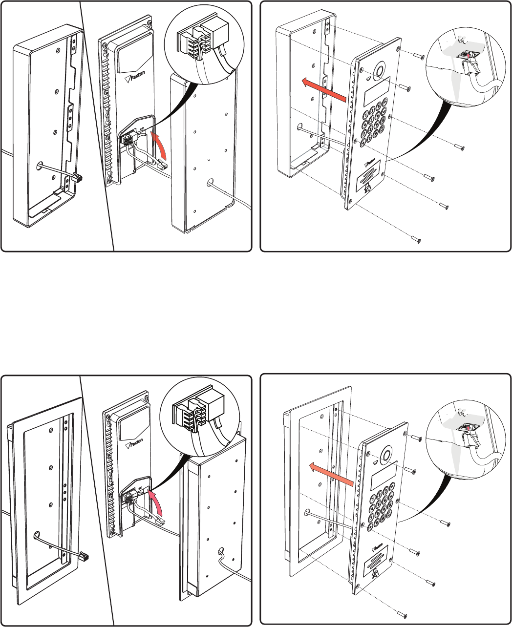
1. Determine the height for the camera and then mark and drill the cable hole with reference to the diagram.
2. Complete the installation of the mounting backbox - Surface or Flush.
3. Connect the Net2 Entry panel to controller.
4. Mount the panel in its backbox.
5. Power up the panel from controller supply (PoE) or external PoE switch.
The display will ask you to set up an Engineer code. The panel checks to see if any monitors also exist on the
network. Any that are detected will now have the engineer code loaded and will store the panel ID that called them
To achieve the best camera performance, try to mount the panel facing away from direct sun or a bright light source.
This will also help the user to read the LCD display.
Where it is not practical to run a patch cable to the rear of the unit, it can be directly wired to the network cable
via the supplied IDC module.
Paxton recommend that the network cable is run to each location and terminated in a network box. A patch
cable should then be used to link the unit to the network. This makes unit replacement or removal for building
maintenance much easier.
A
A
368
39.5
79
44 51 79 75
Ø
5
x 8
136
171
85
330
30.5
329
132
79
39.5
44 51 79 75
Ø
5
x 8
40.5
32.5
Page 3
FLUSH MOUNT
SURFACE MOUNT
Page 4
Initializing a new system
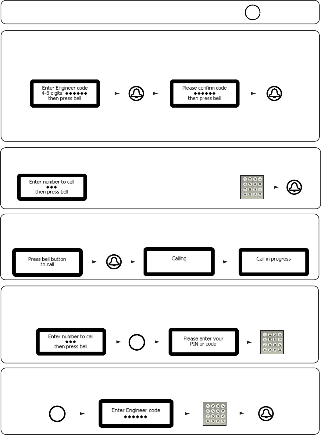
The rst time the system is powered up the panel will request that the Language to be used is conrmed.
It then asks for an Engineer code to be set up. Enter the required code and press the bell key. Conrm the code
and press bell to complete the process.
Use the up and down arrows on the panel to view all the menu options.
The Net2 Entry system uses a separate control unit to operate the door. To associate a panel with its control unit, the
Serial Number of the control unit must be entered.
Only one panel can be associated with a control unit. Multiple panel installations require a control unit for each panel.
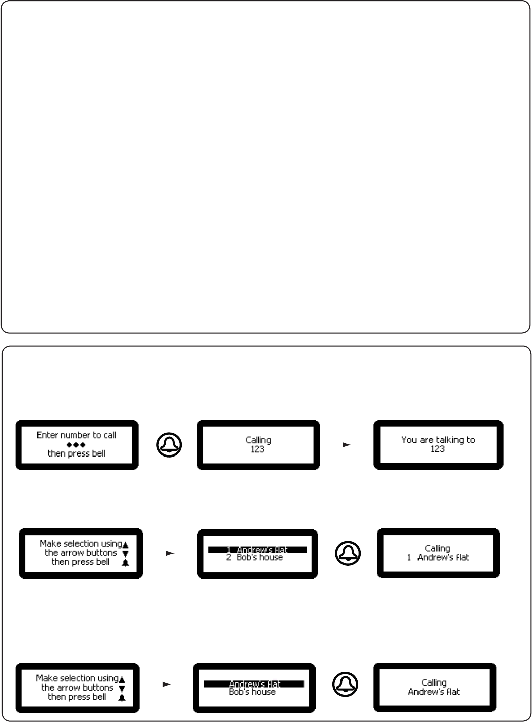
As Monitor units are added to the system, they
will automatically become active. To call a monitor
type in the monitor ID and press the Bell button.
Calling a Monitor unit
Single Occupancy
When only one monitor ID is in use, pressing the Bell button will call the monitor.
How an Occupant gains entry
#
For access control, a Net2 system is required for administration. Once set up, a user can gain entry by presenting their
token to the panel. For PIN or Code entry, the # key must be pressed rst before pressing the numbers on the panel.
X
Use the key to Cancel
To access the Engineer menu from the default screen press *, enter the Engineer code and press the Bell button.
Using the Engineer menu
*
Page 5
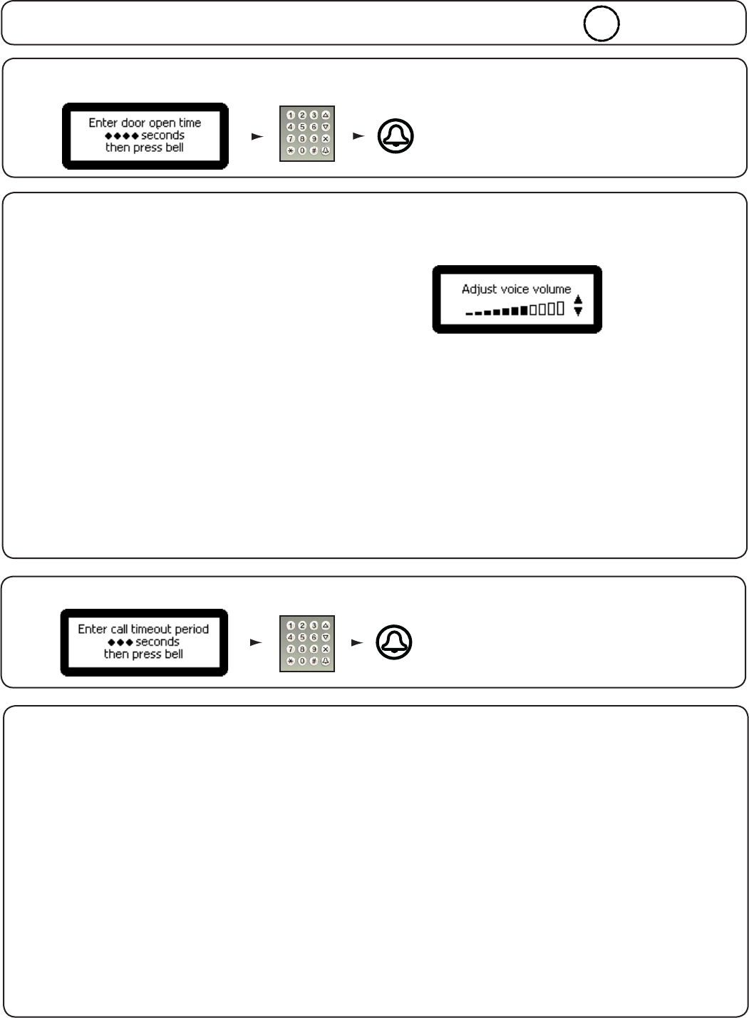
3. Call timeout from the Engineer menu - Press key 3
1. Door open time from the Engineer menu - Press key 1.
1. Set voice volume
2. Volume settings
2. Set keypress tone
This is the time period that the lock will stay
released once the open door button has been
pressed on a monitor. This value may only be
changed when not administered by Net2.
This is the maximum time period that one call
can last. This ensures that the entry panel is not
held busy if a call is not terminated correctly.
This sets the volume of the entry panel speaker.
Use the up and down arrow buttons to adjust then press Bell.
This sets the tone that the entry panel will make when a key is pressed.
Press 1. Click
Press 2. Beep
Press 3. Silent
3. Set door open tone
This sets the tone that the entry panel will make while the lock is released.
Press 1. Beep
Press 2. Buzz
Press 3. Silent
from Volume settings menu - Press key 1
from the Engineer menu - Press key 2
from Volume settings menu - Press key 2
from Volume settings menu - Press key 3
1. Allow video without being called
4. View options
from View options menu - Press key 1
from the Engineer menu - Press key 4
Press 1. Yes
Press 2. No
This allows the camera to be viewed at any time even when not being used to grant access.
2. Allow audio without being called
Press 1. Yes
Press 2. No
This allows the microphone to be turned on at any time even when not being used to grant access.
3. Open the Door without being called
Press 1. Yes
Press 2. No
This allows the 'Unlock door' button to be used while viewing with the camera. The visitor does not need to initiate the call.
from View options menu - Press key 2
from View options menu - Press key 3
X
Use the key to Cancel
Use the up and down arrows on the panel to view all the menu options.
Page 6
1. Set control unit
5. Panel settings
from Panel settings menu - Press key 1
from the Engineer menu - Press key 5
This sets the control unit that the Net2 Entry panel is associated with. Enter the Serial Number of the control unit
and then press Bell.
2. Factory reset
Press 1. Yes
Press 2. No
This returns the Entry panel to Factory settings
3. Backlight
This sets when the Entry panel backlight will be on.
Press 1. Always on
Press 2. Never on
Press 3. Only on in low light
from Panel settings menu - Press key 2
from Panel settings menu - Press key 3
1. Number only
6. Operating Mode
from Set Operating mode menu - Press key 1
from the Engineer menu - Press key 6
This requires the visitor to enter the number without the assistance of a list.
2. Numbered list
3. Text selection
from Set Operating mode menu - Press key 2
from Set Operating mode menu - Press key 3
This displays the monitor IDs to the visitor as a numeric list with its name which they can scroll or enter the number.
This displays the monitor names to the visitor in alphabetical order which they can scroll through and select.
Menu will also respond to numeric input.
4. Video quality from Panel settings menu - Press key 4
This option slows the video rate to reduce the load on busy networks.
Press 1. Low - busy networks
Press 2. Med - small networks
Press 3. High - private wiring

Page 7
1. Set Engineer Code
7. Engineer Access
from Engineer Access menu - Press key 1
from the Engineer menu - Press key 7
This allows the Engineer to change the Engineer code
2. Change Engineer Token
This allows the engineer to add / change the Engineer token
from Engineer Access menu - Press key 2
The engineer can create a token that can be presented to the proximity reader instead of using the engineer code to
gain access to the Engineer Menu.
8. Language from the Engineer menu - Press key 8
This displays the language options available for this monitor.
9. About from the Engineer menu - Press key 9
This displays information about the panel. (e.g. the current version number)

Page 8
4 inch 11 inch 1 1/4 inch
12.95W
100
125k/Hz
- 20 °C ( - 4 °F ) 50 °C ( 122 °F )
IP55
Specications
Power over Ethernet (POE) power rating
Electrical
Environment
Dimensions
Max
Width Height Depth
Features
External use
Panels per system
High
Vandal resistance
Display Backlit LCD
Min
Ethernet bandwidth requirement
Communication
Camera system
Audio system Two way
Full color
I/R illumination Yes
100kb/s multicast 1Mb/s multicast
IEEE 802.3af class 0
Operating temperature
IP Rating
per panel during call
Proximity reader Paxton Access tokens
This device complies with Part 15 of the FCC Rules. Operation is subject to the following two conditions:
(1) this device may not cause harmful interference, and (2) this device must accept any interference received, including
interference that may cause undesired operation. Changes or modications not expressly approved by the party
responsible for compliance could void the user's authority to operate the equipment.
Product compliance and limitations
Wiring methods shall be in accordance with the National Electrical Code (ANSI/NFPA70), local codes, and the authorities
having jurisdiction.
This device complies with Industry Canada licence-exempt RSS standard(s). Operation is subject to the following two
conditions: (1) this device may not cause interference, and (2) this device must accept any interference, including
interference that may cause undesired operation of the device.
Min
Min
Max
Max