Paxton Access 390530 PROXIMITY PANEL MOUNT HID READER User Manual
Paxton Access Ltd PROXIMITY PANEL MOUNT HID READER
User Manual
PAGE 1
Ins-40159-US PROXIMITY panel mount HIDTM reader - UL
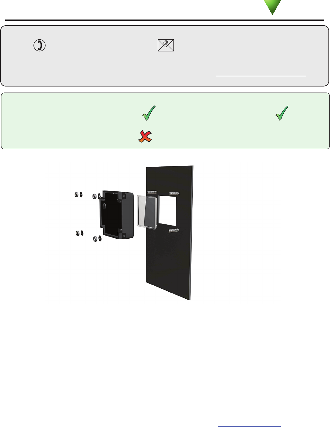
Mounting
Compatible with hands free tokens
Suitability
Security sensitive doors Wet environments
Technical Support
Technical help is available: Monday - Friday from 02:00 AM - 8:00 PM (EST)
1.800.672.7298 supportUS@paxton-access.com
Documentation on all Paxton products can be found on our web site - http://www.paxton-access.com/
Readers mounted together
between readers
12 inches
Paxton
06/08/2011
Token type and conguration
The reader will recognize 125 kHz HIDTM proximity tokens in format to produce a Wiegand output (26 to 50 bit) or
EM4100 tokens to produce an ABA Track2 Clock and Data output.
The reader scans the rst token presented after power up and will match the reader mode to the format discovered.
If no token is read within 3 minutes of powering up, the reader will default to HIDTM. If you require EM4100
operation, power cycle the reader and present an EM4100 token within 3 minutes.
Once in HIDTM or EM4100 mode, the reader will remain in that format.
If used with Net2, the ACU reader port must be congured to read the correct data format.
Where Wiegand cards are used, you must set the correct data format (e.g. Wiegand 26 bits) in the ACU
reader port conguration or create a custom wiegand lter in the Net2 Server Conguration Utility. For
further information see: AN1010 - Conguring custom Wiegand formats < http://paxton.info/990 >
PAGE 2
Cable extensions
Wiring
Wiring methods shall be in accordance with the National Electrical Code (ANSI/NFPA70),
local codes, and the authorities having jurisdiction.
Use Max length Type
Reader / Keypad 500 feet 8 core, shielded - Beldon 9538, Alpha 1298C (22AWG) or equivalent
Cable Specication
Part number Description
390-530-US PROXIMITY panel mount HIDTM reader
Options
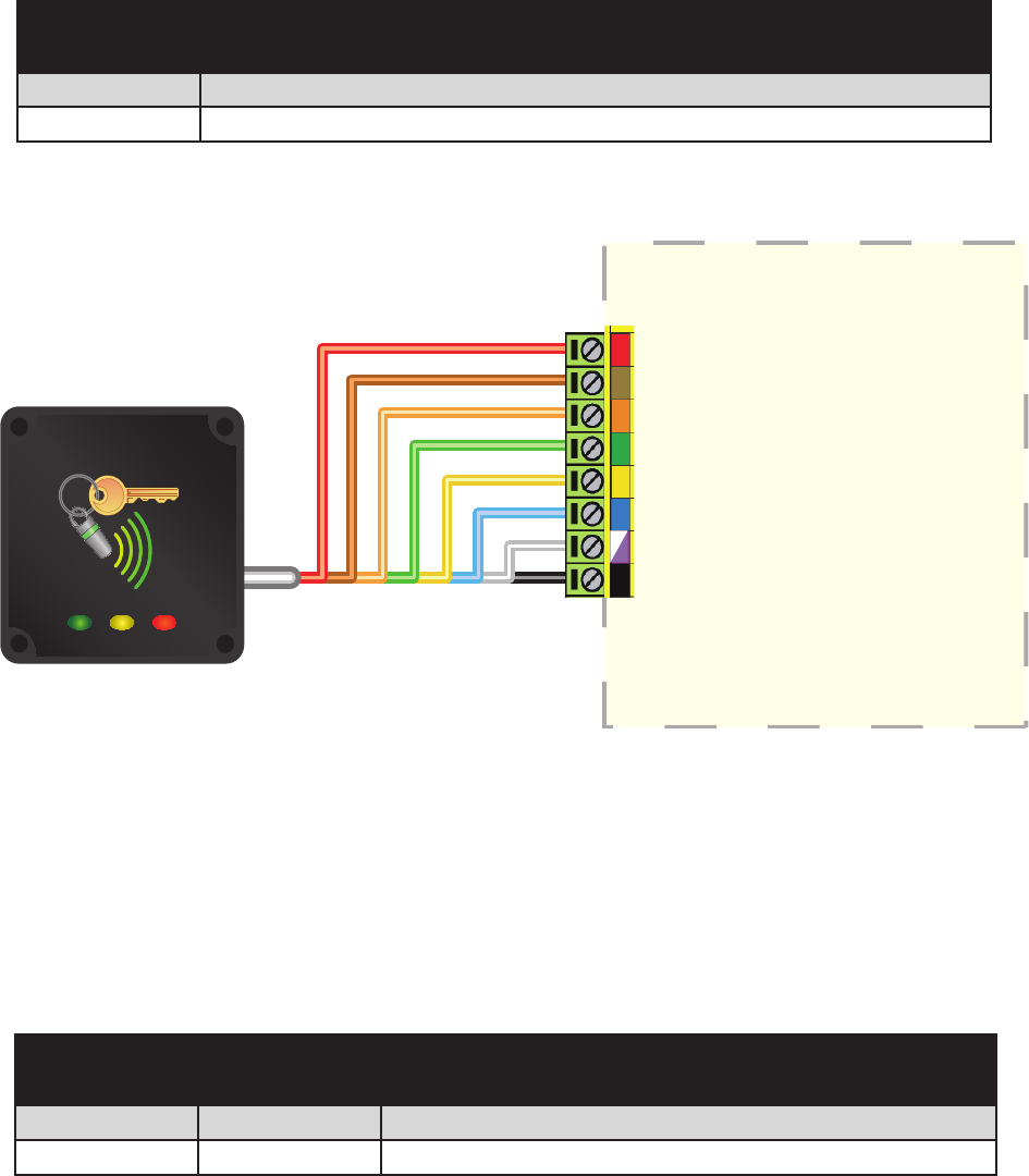
Connection to the Net2
ACU reader port
+12V DC
Red LED
Amber LED
Green LED
Clock/data1
Data/data0
Not Required
0V

PAGE 3
Following the completed installation of this equipment, no further maintenance or testing is required.
It is advisable to ensure that any third party backup power supplies or recovery procedures are checked regularly
to ensure that the operation of the Paxton system is not compromised.
Maintenance
Part number Description
Not required Fits to studs on customer facia
Parts Kit
Reader installation and test
The panel mount reader is designed to t into a door entry panel. It ts behind a reader aperture of industry standard
size (40 mm x 40 mm) and is supplied with a polycarbonate window to match. See front page for tting detail.
Holes are provided in each corner to t over 4 posts set in a 49 mm square formation. Fixings are not provided as
they will normally be supplied with the panel.
When powered up, the reader will beep and all the LED's should display. Presenting a user card to the reader will
cause the LED's to briey change to a single Green or Red LED.
Check the following FAQs section for assistance if any problems are encountered.
FCC Compliance
This device complies with Part 15 of the FCC Rules. Operation is subject to the following two conditions:
(1) this device may not cause harmful interference, and (2) this device must accept any interference
received, including interference that may cause undesired operation. Changes or modications not expressly
approved by the party responsible for compliance could void the user's authority to operate the equipment.

PAGE 4
12V DC
140 mA
115 kHz 135 kHz
-35 °C ( -31 °F ) +66 °C ( + 151 °F )
IPX7
2” 11/2”
2 1/4 ”2 1/4 ”11/16 ”
40 mm (1
19/32”) 40 mm (1
19/32”) -
49 mm (1
30/32”) 49 mm (1
30/32”)
Here is the list of topics about this product that receive the most technical support inquiries.
We list them here to help you speed up the installation and trouble shooting process.
Technical Help
1 - Readers/Keypads not working.
Q- Software settings - Conrm that the settings of the reader or keypad are correct.
Q- Connections - Check the wiring and integrity of the connectors. If possible, test this reader on the other port.
Q- Extended cable - Belden 9538/9540 should be used up to a maximum of 500 feet. Twisted pair alarm cable should
Q not be used. To conrm that an extended reader cable is not at fault, wire the reader directly to the port.
Q- Supply voltage - Conrm that the voltage is within specication. (see table)
Q- User token - Conrm that the user token used for testing is OK by presenting it to a known working reader.
Q- Interference - Conrm whether the reader works when tested 'in hand' and not mounted on the wall.
Q PROXIMITY readers should not be mounted back to back or close to other RF devices.
2 - Readers / Keypads - Extending cable.
QOnly Belden CR9538 / 9540 or a UL equivalent can be used for cable extensions. The maximum run is 500 feet.
3 - Net2 - Using a door reader as a desktop reader.
QIt is possible to congure a door reader to operate as a desktop reader:
Q1 - Select the doors menu in the left hand Net2 pane.
Q2 - Click on the door you wish to change the reader to act as a desktop reader.
Q3 - Under the relevant reader tab, change the reader operating mode to 'Desktop Reader'.
Q4 - The PC displays 'Would you like to accept desktop reader events from this reader at the PC?' ; click 'Yes'
Q Now when you present a blank or existing token to that reader it will allow you to add this new token or edit
Q the existing one.
NOTE:QRemember to return the operating mode to the original setting once the cards have been read
Q or users will not be able to gain access through the reader.
Q KP Reader - Ensure that Keypad type is set to 'None', otherwise the Desktop reader option will not be available.
4 - Net2. What to do if a user has no access - Check the reader LED's when a card is shown.
Q- No LED's - the reader has no power.
Q- No change in display - try the card on a known working reader. If there is still no response, replace the card.
Q- Green LED ashing when a card is presented; check relay 1 LED to check for activity and also the lock wiring.
Q- Red LED is ashing when a card is presented; check the validity of the user at the PC.
Q Check user's access level and ensure they should have access by clicking on Current Validity.
Q Check the 'Valid Until' date and conrm this has not expired.
Q- Reinstate the ACU from the doors screen. Select the ACU's you wish to reinstate and then click OK.
Voltage
Carrier frequency
Specications
Operating temperatures - all items
Electrical
Environment
Dimensions
Min Max
Width Height Depth
Current
Cable length
Read Range Token Keyfob Hands Free Token
Outdoor Use
Min Max
Panel mount reader
Window size
Mounting studs - Square formation See front page for position
Not Compatible
Reader xings are in metric to match industry standard access panel readers
Waterproof
3 metres