Paxton Access 500010 125 kHz Proximity Reader User Manual INSTRUCTION PROXIMITY marine reader
Paxton Access Ltd 125 kHz Proximity Reader INSTRUCTION PROXIMITY marine reader
Manual
Ins-30045-US PROXIMITY marine reader
06/07/2007
Technical Support
Technical help is available: Monday - Friday from 5am - 5pm PST / 8am - 8pm EST
Other documentation on all Paxton products can be found on our web site - http://www.paxton-access.com/
1 800 672 PAXT support@paxton-access.co.uk
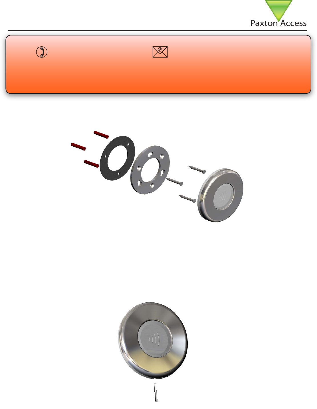
Fitting
Fix the back plate to the wall with the stainlesss steel screws provided in the tting kit. The small slot in the plate
edge should be positioned at the bottom.
Where the reader is to be tted to a smooth surface, bulkhead, etc. a gasket is supplied to provide a weatherproof
seal between the back plate and the mounting surface. (The reader has its own integral seal)
Locate the reader in the keyhole slots provided in the back plate. Make sure that the locking pin is close to the slot
in the edge of the back plate. Rotate the reader clockwise until the locking pin engages in the slot.
To remove the reader, insert a small screwdriver into the cut out provided and use it to lift the locking pin. The
reader can then be rotated anticlockwise to release it from the back plate.
Red
Brown
Orange
Green
Yellow
Blue
Mauve
Black/White
Brown
Yellow
Reader 1
Orange
Keypad 1
+12v
0v
N.C.
N.O.
Com
N.C.
N.O.
Com
Alarm Output
0v
Contact
0v
Exit
0v
Tamper
PSU
Rx
Tx
Relay 1
Relay 2
Exit
Contact
Tamper
PSU
OK
5v
12v
Red
Brown
Orange
Green
Yellow
Blue
Mauve
Black/White
Brown
Yellow
Orange
Reader 2
Keypad 2
Power
Relay 1Relay 2Inputs
Network
CAT5 cable coding
White/Green
Green
White/Orange
Orange
1
2
3
4
Screen or spare cores
from network cable
Serial number
241821
Test ID: 012345678901
z-1440
3
2 4 8 9 8 0 0 0 0 0
4
Red
Brown
Orange
Green
Yellow
Blue
Mauve
Exit
Contact
Black
Card reader or keypad
12v
0v
N.C.
N.O.
Com
Bell
PowerDoor relay
Alarm
witch
2
S
Control
unit
Inputs
White Labelled control units only provide
5v at the Red terminal. The red power wire
for the reader should be connected directly
to the 12v PCB supply terminal - as per
diagram.
Cable extensions
Red 12v dc
Brown
Orange
Green
Yellow
Blue
Mauve
Black/White
Brown
Yellow
Reader 1
Orange
Keypad 1
+12v
0v
N.C.
N.O.
Com
N.C.
N.O.
Com
Alarm Output
0v
Contact
0v
Exit
0v
Tamper
PSU
Rx
Tx
Relay 1
Relay 2
Exit
Contact
Tamper
PSU
OK
5v
12v
Red
Brown
Orange
Green
Yellow
Blue
Mauve
Black/White
Brown
Yellow
Orange
Reader 2
Keypad 2
Power
Relay 1Relay 2Inputs
Network
CAT5 cable coding
White/Green
Green
White/Orange
Orange
1
2
3
4
Screen or spare cores
from network cable
CAUTION: for 12v d.c. readers only. For
correct connection of old 5v readers, refer to
instructions.
Serial number
241821
Test ID: 012345678901
z-1440
3
2 4 8 9 8 0 0 0 0 0
4
Red 12V
Brown
Orange
Green
Yellow
Blue
Mauve
Exit
Contact
Black
Card reader or keypad
12v
0v
N.C.
N.O.
Com
Bell
PowerDoor relay
Alarm
witch
2
S
Control
unit
Inputs
CAUTION: For 12V d.c. readers only.
For correct connection of old readers,
refer to instructions.
Readers can be extended using Belden CR9540 10-core overall screened cable. The maximum cable length
between reader and control unit is 100 yards.
Wiring

1 - Readers/Keypads not working
. Software settings - Conrm that the settings of the reader or keypad are correct.
. Connections - Check the wiring and integrity of reader/keypad terminal connections.
. To conrm that an extended reader cable is not at fault, wire the reader direct into the reader port. If the reader
works, this indicates a problem with the cable.
. Supply voltage - conrm that the reader has sufcient voltage.
. User token - Check that the user token used for testing the reader is operational.
. Interference - Conrm whether the reader works when tested ‘in hand’ and not mounted on the wall. Ensure that
readers are not mounted back to back or there is not interference from other RF devices.
2 - Readers / Keypads - Extending cable
. Only Belden CR9538 /9540 can be used for cable extensions. CR9538 is 8 core for up to 25m, CR9540 10 core
for 25-100m (maximum extension). When using CR9540, the two additional cores should be used to double up for
power.
3 - Net2 - What to do if a user has no access
. Check the reader LEDs when a card is shown:
. No LEDs - the reader has no power.
. No change in display - try the card on a known working readers. If there is still no response, replace the card.
. Green LED ashing when a card is presented, check the Relay 1 LED to check activity and the wiring to the lock.
. Red LED is ashing when a card is presented, check the validity of the user at the PC.
. - Check user’s access level and ensure they have access by clicking on Current Validity.
. - Check the ‘Valid Until’ date and conrm this has not expired.
. Reinstate the ACU from the doors screen. Select the ACU’s you wish to reinstate and then click OK.
4 - Switch2 - Adding an additional card pack
. You need to be in possession of the original enrolment card. Present the original enrolment card to the reader
and the Amber LED will ash, Green & Red LEDs will be off, then present the Enrolment card from the new card
pack; the reader will beep and all LEDS will be lit. The additional cards will now be valid. Repeat this with each
reader and with any additional card packs. Any valid enrolment card can be used to add further packs. This is the
same for enrolling function card packs onto a system.
5 - Switch2 - How to reset the controller
. Disconnect the power and remove the wires from the Green and Mauve terminals
. Insert a wire link between the Green and Mauve terminals
. Reconnect the power (the unit will bleep 4 times)
. Disconnect the power and remove the link wire, reconnect the Green and Mauve wires
. Reconnect the power (the unit will bleep 3 times per second). The unit is ready to be enrolled.
Here is the list of topics about this product that receive the most technical support enquiries. We
list them here to help you speed up the installation and trouble shooting process.
Frequently asked questions
Readers mounted together between
readers
300mm
Mounted on metal surface
Suitability
Security sensitive doors
Wet environments

-25 °C (-4 °F) +55 °C (+131°F)
IPX7
5 yards
8v DC 14v DC
130 mA
125 kHz
600 µs
1 1/2” 1” 15”
4” 5/8”
Voltage
Clock and data bit period
Carrier frequency
Specications
Operating temperatures - all items
Electrical
Environment
Current
Cable length
Read Range Token Keyfob
Waterproof
Dimensions
Min
Diameter
Max
Min Max
Depth
Hands Free Token
The declaration of conformity may be
consulted at - http://paxton.info/596
FCC Compliance
This device complies with Part 15 of the FCC Rules. Operation is subject to the following two conditions: (1) this
device may not cause harmful interference, and (2) this device must accept any interference received, including
interference that may cause undesired operation.
Changes or modications not expressly approved by the party responsible for compliance
could void the user’s authority to operate the equipment.