PG.74A.01.T.E Brochure
1000500965-Brochure 1000500965-Brochure 1000500965-Brochure B6 unilog cesco-content
2016-10-27
: Pdf 1000349133-Brochure 1000349133-Brochure B6 unilog
Open the PDF directly: View PDF ![]() .
.
Page Count: 192 [warning: Documents this large are best viewed by clicking the View PDF Link!]

March 1999
PG.74A.01.T.E
Cutler-Hammer 1
Circuit Breaker Electronic Catalog
Navigation Chart of Attached CD-ROM . . . . . . . . . . . . 192
■Product Guide
■Selection Data
■Time Current
Curves
■Dimensions
Miniature and Molded Case Circuit Breakers
Table of Contents
Miniature Circuit Breakers
Selection Guide . . . . . . . . . . . . . . . . . . . . . . . . . . . . . . . . . 2
QUICKLAG® Industrial Circuit Breakers
Circuit Breakers, Plug-on Types HQP, QPHW,
QHPX, QHPW. . . . . . . . . . . . . . . . . . . . . . . . . . . . . . . . . 5
Ground Fault Circuit Breakers, Plug-on Types
QPGF, QPHGF . . . . . . . . . . . . . . . . . . . . . . . . . . . . . . . . 6
Ground Fault Equipment Protectors, Plug-on Types
QPGFEP, QPHGFEP . . . . . . . . . . . . . . . . . . . . . . . . . . . . 6
Circuit Breakers, Bolt-on Types BA, QBHW, HBAX,
HBAW . . . . . . . . . . . . . . . . . . . . . . . . . . . . . . . . . . . . . . . 7
Ground Fault Circuit Breakers, Bolt-on Types
QBGF, QBHGF . . . . . . . . . . . . . . . . . . . . . . . . . . . . . . . . 8
Ground Fault Equipment Protectors, Bolt-on Types
QBGFEP, QBHGFEP. . . . . . . . . . . . . . . . . . . . . . . . . . . . 8
Circuit Breakers, Cable-in/Cable-out
1-Inch per Pole Types QC, QCHW, QHCX, QHCW . . . 9
1/2-Inch per Pole Types QCR, QCF, QCRH, QCFH. . . 10
Ground Fault Circuit Breakers, Cable-in/Cable-out
Types QCGF, QCHGF . . . . . . . . . . . . . . . . . . . . . . . . . 13
Ground Fault Equipment Protectors, Cable-in/
Cable-out Types QPGFEP, QCHGFEP. . . . . . . . . . . . . 13
Solenoid-operated, Remote-controlled Types
GHBS, GBHS . . . . . . . . . . . . . . . . . . . . . . . . . . . . . . . . 14
International Rated Circuit Breakers . . . . . . . . . . . . . . . . 16
Special Application Breakers. . . . . . . . . . . . . . . . . . . . . . 17
Accessories . . . . . . . . . . . . . . . . . . . . . . . . . . . . . . . . . . . . 18
Factory Modifications, Factory Installed Terminals . . . 19
Supplementary Protectors
Type SPCL Current Limiting . . . . . . . . . . . . . . . . . . . . . . 20
Type SPHM Hydraulic Magnetic . . . . . . . . . . . . . . . . . . . 23
Molded Case Circuit Breakers
Selection Guide . . . . . . . . . . . . . . . . . . . . . . . . . . . . . . . . . 3
Series C Circuit Breakers
G-Frame . . . . . . . . . . . . . . . . . . . . . . . . . . . . . . . . . . . . . . 25
F-Frame. . . . . . . . . . . . . . . . . . . . . . . . . . . . . . . . . . . . . . . 31
J-Frame. . . . . . . . . . . . . . . . . . . . . . . . . . . . . . . . . . . . . . . 37
K-Frame . . . . . . . . . . . . . . . . . . . . . . . . . . . . . . . . . . . . . . 43
L-Frame. . . . . . . . . . . . . . . . . . . . . . . . . . . . . . . . . . . . . . . 55
M-Frame . . . . . . . . . . . . . . . . . . . . . . . . . . . . . . . . . . . . . . 67
N-Frame . . . . . . . . . . . . . . . . . . . . . . . . . . . . . . . . . . . . . . 75
R-Frame . . . . . . . . . . . . . . . . . . . . . . . . . . . . . . . . . . . . . . 89
Specific Application Circuit Breakers
Motor Circuit Protectors . . . . . . . . . . . . . . . . . . . . . . . . 107
Earth Leakage. . . . . . . . . . . . . . . . . . . . . . . . . . . . . . . . . 113
Current Limiting
Non-fused . . . . . . . . . . . . . . . . . . . . . . . . . . . . . . . . . 115
Fused . . . . . . . . . . . . . . . . . . . . . . . . . . . . . . . . . . . . . 117
Engine Generator. . . . . . . . . . . . . . . . . . . . . . . . . . . . . . 129
Direct Current. . . . . . . . . . . . . . . . . . . . . . . . . . . . . . . . . 133
Mining Service . . . . . . . . . . . .See CD-ROM SA.74A.01.T.E
Navy . . . . . . . . . . . . . . . . . . . .See CD-ROM SA.74A.01.T.E
Add-on Ground Fault Protection . . . . . . . . . . . . . . . . . 135
Internal Accessories
Alarm Switch . . . . . . . . . . . . . . . . . . . . . . . . . . . . . . . . . 139
Auxiliary Switch. . . . . . . . . . . . . . . . . . . . . . . . . . . . . . . 142
Auxiliary and Alarm Switch Combination . . . . . . . . . . 145
Shunt Trip. . . . . . . . . . . . . . . . . . . . . . . . . . . . . . . . . . . . 147
Low Energy Shunt Trip . . . . . . . . . . . . . . . . . . . . . . . . . 152
Undervoltage Release Mechanism. . . . . . . . . . . . . . . . 153
Terminal Block . . . . . . . . . . . . . . . . . . . . . . . . . . . . . . . . 160
Communication Kits . . . . . . . . . . . . . . . . . . . . . . . . . . . 160
External Accessories
Termination Hardware . . . . . . . . . . . . . . . . . . . . . . . . . 161
Mounting Hardware. . . . . . . . . . . . . . . . . . . . . . . . . . . . 163
Locking Devices . . . . . . . . . . . . . . . . . . . . . . . . . . . . . . . 168
Interlocking Devices. . . . . . . . . . . . . . . . . . . . . . . . . . . . 170
Electric Operators . . . . . . . . . . . . . . . . . . . . . . . . . . . . . 172
Plug-in Adapters . . . . . . . . . . . . . . . . . . . . . . . . . . . . . . 174
Rear Connecting Studs . . . . . . . . . . . . . . . . . . . . . . . . . 175
Panelboard Connecting Straps. . . . . . . . . . . . . . . . . . . 177
Handle Mechanisms . . . . . . . . . . . . . . . . . . . . . . . . . . . 178
Circuit Breaker Enclosures . . . . . . . . . . . . . . . . . . . . . . 187
Standards . . . . . . . . . . . . . . . . . . . . . . . . . . . . . . . . . . . . 191
Copyright Cutler-Hammer Inc., 1999.
All Rights Reserved.
Website: www.cutlerhammer.eaton.com
PG.74A.01.T.E
Cutler-Hammer
2March 1999
Miniature Circuit Breakers
Selection Guide
Circuit Breaker Type Codes: P Plug-in; B Bolt-on; C Cable-in/Cable-out; GF Ground Fault, 5 ma; GFEP Ground Fault, 30 ma.
For Types SPCL and SPHM Supplementary Protectors, see pages 20 and 23.
For Types GHBS and GBHS Solenoid-operated, Remote-controlled Circuit Breakers, see page 14.
Circuit
Breaker
Type
Circuit
Breaker
Type Code
Cont.
Ampere
Rating
At 40°C
Number
of
Poles
Volts Federal
Spec.
W-C-375b
Interrupting Ratings rms Symmetrical Amperes Page
Number
Ac Dc Ac Ratings Volts Dc➁
120 120/240 240 24-48 62.5 80
Quicklag Industrial Circuit Breakers➀
Plug-in, Bolt-on, Cable-in/Cable-out
HQP
HQP
HQP
P 10-70
10-125
10-100
1
2
2, 3
120/240
120/240
240
24, 48, 62.5
24, 48, 80
–
10a, 11a, 12a
10a, 12a
10b, 11b, 12b
–
–
–
10,000
10,000
–
–
–
10,000
5,000
5,000
–
➂
5,000
–
–
5,000
–
5
5
5
QPHW
QPHW
QPHW
P 15-70
15-125
15-100
1
2
2, 3
120/240
120/240
240
24, 48, 62.5
24, 48, 80
–
14a
14a
14b
–
–
–
22,000
22,000
–
–
–
22,000
5,000
5,000
–
➂
5,000
–
–
5,000
–
5
5
5
QHPX
QHPX
QHPX
P 15-70
15-100
15-100
1
2
3
120/240
120/240
240
24, 48, 62.5
24, 48, 80
–
–
–
–
–
–
–
42,000
42,000
–
–
–
42,000
5,000
5,000
–
➂
5,000
–
–
5,000
–
5
5
5
QHPW
QHPW
QHPW
P 15-30
15-30
15-20
1
2
3
120/240
120/240
240
24, 48, 62.5
24, 48, 80
–
15a
15a
15b
–
–
–
65,000
65,000
–
–
–
65,000
5,000
5,000
–
➂
5,000
–
–
5,000
–
5
5
5
QPGF
QPGF
P, GF 15-40
15-50
1
2
120
120/240
–
–
10a, 11a, 12a
10a, 11a, 12a
10,000
–
–
10,000
–
–
–
–
–
–
–
–
6
6
QPHGF
QPHGF
P, GF 15-30
15-50
1
2
120
120/240
–
–
10a, 11a, 12a
10a, 11a, 12a
22,000
–
–
22,000
–
–
–
–
–
–
–
–
6
6
QPGFEP
QPGFEP
P, GFEP 15-40
15-50
1
2
120
120/240
–
–
–
–
10,000
–
–
10,000
–
–
–
–
–
–
–
–
6
6
QPHGFEP
QPHGFEP
P, GFEP 15-30
15-30
1
2
120
120/240
–
–
–
–
22,000
22,000
–
22,000
–
–
–
–
–
–
–
–
6
6
BAB
BAB
BAB
B 10-70
10-125
10-100
1
2
2, 3
120/240
120/240
240
24, 48, 62.5
24, 48, 80
–
10a, 11a, 12a
10a, 12a
10b, 11b, 12b
–
–
–
10,000
10,000
–
–
–
10,000
5,000
5,000
–
➂
5,000
–
–
5,000
–
7
7
7
QBHW
QBHW
QBHW
B 15-70
15-125
15-100
1
2
2, 3
120/240
120/240
240
24, 48, 62.5
24, 48, 80
–
14a
14a
14b
–
–
–
22,000
22,000
–
–
–
22,000
5,000
5,000
–
➂
5,000
–
–
5,000
–
7
7
7
HBAX
HBAX
HBAX
B 15-70
15-100
15-100
1
2
3
120/240
120/240
240
24, 48, 62.5
24, 48, 80
–
–
–
–
–
–
–
42,000
42,000
–
–
–
42,000
5,000
5,000
–
➂
5,000
–
–
5,000
–
7
7
7
HBAW
HBAW
HBAW
B 15-30
15-30
15-20
1
2
3
120/240
120/240
240
24, 48, 62.5
24, 48, 80
–
15a
15a
15b
–
–
–
65,000
65,000
–
–
–
65,000
5,000
5,000
–
➂
5,000
–
–
5,000
–
7
7
7
QBGF
QBGF
B, GF 15-40
15-50
1
2
120
120/240
–
–
10a, 11a, 12a
10a, 11a, 12a
10,000
–
–
10,000
–
–
–
–
–
–
–
–
8
8
QBHGF
QBHGF
B, GF 15-30
15-30
1
2
120
120/240
–
–
10a, 11a, 12a
10a, 11a, 12a
22,000
–
–
22,000
–
–
–
–
–
–
–
–
8
8
QBGFEP
QBGFEP
B, GFEP 15-40
15-50
1
2
120
120/240
–
–
–
–
10,000
–
–
10,000
–
–
–
–
–
–
–
–
8
8
QBHGFEP
QBHGFEP
B, GFEP 15-30
15-30
1
2
120
120/240
–
–
–
–
22,000
22,000
–
22,000
–
–
–
–
–
–
–
–
8
8
QC
QC
QC
C 10-70
10-100
10-100
1
2
2, 3, 4
120/240
120/240
240
24, 48, 62.5
24, 48, 80
–
10a, 11a, 12a
10a, 12a
10b, 11b, 12b
–
–
–
10,000
10,000
–
–
–
10,000
5,000
5,000
–
➂
5,000
–
–
5,000
–
9
9
9
QCF
QCF
QCF
QCR
QCR
QCR
C 10-60
15-20
15-30
10-60
15-20
15-30
1, 2
1, 2
2, 3
1, 2
1, 2
2, 3
120/240
120/240
240
120/240
120/240
240
24, 48, 62.5
24, 48, 62.5
24, 48, 62.5
24, 48, 62.5
24, 48, 62.5
24, 48, 62.5
–
–
–
–
–
–
10,000
22,000
–
10,000
22,000
–
10,000
–
10,000
10,000
–
10,000
–
–
–
–
–
–
3,000
3,000
3,000
3,000
3,000
3,000
➂
3,000
3,000
2,000
3,000
3,000
–
–
–
–
–
–
10
10
10
10
10
10
QCHW
QCHW
QCHW
C 15-70
15-100
15-100
1
2
2, 3
120/240
120/240
240
24, 48, 62.5
24, 48, 80
–
14a
14a
14b
–
–
–
22,000
22,000
–
–
–
22,000
5,000
5,000
–
➂
5,000
–
–
5,000
–
9
9
9
QHCX
QHCX
QHCX
C 15-70
15-100
15-100
1
2
3
120/240
120/240
240
24, 48, 62.5
24, 48, 80
–
–
–
–
–
–
–
42,000
42,000
–
–
–
42,000
5,000
5,000
–
➂
5,000
–
–
5,000
–
9
9
9
QHCW
QHCW
QHCW
C 15-30
15-30
15-20
1
2
3
120/240
120/240
240
24, 48, 62.5
24, 48, 80
–
15a
15a
15b
–
–
–
65,000
65,000
–
–
–
65,000
5,000
5,000
–
➂
5,000
–
–
5,000
–
9
9
9
QCGF
QCGF
C, GF 15-40
15-50
1
2
120
120/240
–
–
–
–
10,000
–
–
10,000
–
–
–
–
–
–
–
–
13
13
QCHGF
QCHGF
C, GF 15-30
15-30
1
2
120
120/240
–
–
–
–
22,000
–
–
22,000
–
–
–
–
–
–
–
–
13
13
QCGFEP
QCGFEP
C, GFEP 15-40
15-50
1
2
120
120/240
–
–
–
–
10,000
–
–
10,000
–
–
–
–
–
–
–
–
13
13
QCHGFEP
QCHGFEP
C, GFEP 15-30
15-30
1
2
120
120/240
–
–
–
–
22,000
–
–
22,000
–
–
–
–
–
–
–
–
13
13
➁Two-pole dc interrupting ratings based on
2 poles connected in series.
➀QUICKLAG circuit breakers are suitable for
application in relative humidity 0-95% non-
condensating.
➂62.5 Vac interrupting rating is 3800 AIC 10-50
amperes and 2500 AIC 55-100 amperes
continuous.

March 1999
PG.74A.01.T.E
Cutler-Hammer 3
Molded Case Circuit Breakers
Selection Guide
Circuit
Breaker
Type
Cont.
Amp
Rating
At 40°C
No.
Poles
Volts Type
of
Trip➀
Federal
Spec.
W-C-375b
UL Listed Interrupting Ratings rms Symmetrical Amperes Page
Number
Ac Dc Ac Ratings Volts Dc➁
120 120/240 240 277 480 600 125 250 125/250
Series C® Industrial Circuit Breakers
G-Frame
GB
GB
15-100
15-100
1
2, 3
120
240
125
125/250
N.I.T. 11a
10b, 11b,
12b, 14b,
15b
65,000
–
–
–
–
65,000
–
–
–
–
–
–
14,000
–
–
–
–
14,000
27
27
GHB
GHB
GHB
GHB
15-100
15-100
15-100
15-100
1
2, 3
1
2, 3
120
240
277
277/480
125
125/250
125
125/250
N.I.T. 11a
10b, 11b,
12b, 14b,
15b
12c, 13a
13b
65,000
–
–
–
–
–
–
–
–
65,000
–
–
–
–
14,000
14,000
–
–
–
14,000
–
–
–
–
14,000
–
14,000
–
–
–
–
–
–
14,000
–
14,000
27
27
27
27
GC
GC
15-100
15-100
1
2, 3
120
240
125
125/250
N.I.T. 11a
10b, 11b,
12b, 14b,
15b
65,000
–
–
–
–
65,000
–
–
–
–
–
–
14,000
–
–
–
–
14,000
28
28
GHC
GHC
GHC
GHC
15-100
15-100
15-100
15-100
1
2, 3
1
2, 3
120
240
277
277/480
125
125/250
125
125/250
N.I.T. 12c, 13a
13b
12c, 13a
13b
65,000
–
–
–
–
–
–
–
–
65,000
–
–
–
–
14,000
14,000
–
–
–
14,000
–
–
–
–
14,000
–
14,000
–
–
–
–
–
–
14,000
–
14,000
28
28
28
28
F-Frame
GD 15-100 3 480 250 N.I.T. 13b – – 65,000 – 22,000 – – 10,000 – 26
ED
EDH
EDC
100-255
100-255
100-255
2, 3
2, 3
2, 3
240
240
240
125
125
125
N.I.T. 12b
14b
1
–
–
–
–
–
–
65,000
100,000
200,000
–
–
–
–
–
–
–
–
–
10,000
10,000
10,000
–
–
–
–
–
–
32
32
32
EHD
EHD
15-100
15-100
1
2, 3
277
480
125
250
N.I.T. 13a
13b
–
–
–
–
–
18,000
14,000
–
–
14,000
–
–
10,000
–
–
10,000
–
–
32
32
FDB
FDB
15-150
15-150
2, 3
4
600
600
250
250
N.I.T. 18a
➂
–
–
–
–
18,000
18,000
–
–
14,000
14,000
14,000
14,000
–
–
10,000
10,000
–
–
32
32
FD
FD
FD
15-150
15-150
15-150
1
2, 3
4
277
600
600
125
250
250
N.I.T. 13a
22a
➂
–
–
–
–
–
–
–
65,000
65,000
25,000
–
–
–
25,000
25,000
–
18,000
18,000
10,000
–
–
–
10,000
10,000
–
–
–
32
32
32
HFD
HFD
HFD
15-150
15-150
15-150
1
2,3
4
277
600
600
125
250
250
N.I.T. 13a
22a
➂
–
–
–
–
–
–
–
100,000
100,000
65,000
–
–
–
65,000
65,000
–
25,000
25,000
10,000
–
–
–
20,000
20,000
–
–
–
33
33
33
FDC
FDC
15-150
15-150
2, 3
4
600
600
250
250
N.I.T. 24a
➂
–
–
–
–
200,000
200,000
–
–
100,000
100,000
35,000
35,000
–
–
20,000
20,000
–
–
33
33
J-Frame
JDB
JD
HJD
JDC
70-250
70-250
70-250
70-250
2, 3
2, 3, 4
2, 3, 4
2, 3, 4
600
600
600
600
250
250
250
250
N.I.T.
I.T
I.T
I.T
22a
22a
22a
22a
–
–
–
–
–
–
–
–
65,000
65,000
100,000
200,000
–
–
–
–
25,000
25,000
65,000
100,000
18,000
18,000
25,000
35,000
–
–
–
–
10,000
10,000
22,000
22,000
–
–
–
–
39
38
38
38
K-Frame
DK 250-400 2, 3 240 250 N.I.T. 14b – – 65,000 – – – – 10,000 – 47
KDB
KD
CKD
HKD
CHKD
KDC
100-400
100-400
100-400
100-400
100-400
100-400
2, 3
2, 3, 4
2, 3, 4
2, 3, 4
2, 3, 4
2, 3, 4
600
600
600
600
600
600
250
250
250
250
250
250
N.I.T.
I.T
I.T
I.T
I.T
I.T
23a
23a
23a
23a
23a
23a
–
–
–
–
–
–
–
–
–
–
–
–
65,000
65,000
65,000
100,000
100,000
200,000
–
–
–
–
–
–
35,000
35,000
35,000
65,000
65,000
100,000
25,000
25,000
25,000
35,000
35,000
50,000
–
–
–
–
–
–
10,000
10,000
10,000
22,000
22,000
22,000
–
–
–
–
–
–
47
45, 46, 49
48, 50
45, 46, 49
48, 50
45, 46, 49
L-Frame
LDB
LD
CLD
HLD
CHLD
LDC
CLDC
300-600
300-600
300-600
300-600
300-600
300-600
300-600
2, 3
2, 3, 4
2, 3, 4
2, 3, 4
2, 3, 4
2, 3, 4
2, 3, 4
600
600
600
600
600
600
600
250
250
250
250
250
250
250
N.I.T.
I.T
I.T
I.T
I.T
I.T
I.T
23a
23a
23a
23a
23a
23a
23a
–
–
–
–
–
–
–
–
–
–
–
–
–
–
65,000
65,000
65,000
100,000
100,000
200,000
200,000
–
–
–
–
–
–
–
35,000
35,000
35,000
65,000
65,000
100,000
100,000
25,000
25,000
25,000
35,000
35,000
50,000
50,000
–
–
–
–
–
–
–
22,000
22,000
22,000
25,000
25,000
25,000
25,000
–
–
–
–
–
–
–
58
57, 59
58, 61
57, 59
61
57, 60
62
➀N.I.T. is non-interchangeable trip unit and
I.T. is interchangeable trip unit.
➁Two-pole circuit breaker, or two poles of
three-pole circuit breaker at 250 Vdc.
➂Not defined in W-C-375b.

PG.74A.01.T.E
Cutler-Hammer
4March 1999
Molded Case Circuit Breaker
Standards
Selection Guide
, Continued
Circuit
Breaker
Type
Cont.
Amp
Rating
At 40°C
No.
Poles
Volts Type
of
Trip➀
Federal
Spec.
W-C-375b
UL Listed Interrupting Ratings rms Symmetrical Amperes Page
Number
Ac Dc Ac Ratings Volts Dc➁
120 120/240 240 277 480 600 125 250 125/250
Series C® Industrial Circuit Breakers
M-Frame
MDL
CMDL
HMDL
CHMDL
300-800
300-800
300-800
300-800
2, 3
2, 3
2, 3
2, 3
600
600
600
600
250
250
250
250
I.T.
I.T.
I.T.
I.T.
23a
23a
23a
23a
–
–
–
–
–
–
–
–
65,000
65,000
100,000
100,000
–
–
–
–
50,000
50,000
65,000
65,000
25,000
25,000
35,000
35,000
–
–
–
–
22,000
22,000
25,000
25,000
–
–
–
–
69, 70
70
69, 70
70
N-Frame
ND
CND
HND
CHND
NDC
CNDC
600-1200
600-1200
600-1200
600-1200
600-1200
600-1200
3, 4
3, 4
3, 4
3, 4
3, 4
3, 4
600
600
600
600
600
600
–
–
–
–
–
–
N.I.T.
N.I.T.
N.I.T.
N.I.T.
N.I.T.
N.I.T.
23A
23A
23A
23A
23A
23A
–
–
–
–
–
–
–
–
–
–
–
–
65,000
65,000
100,000
100,000
200,000
200,000
–
–
–
–
–
–
50,000
50,000
65,000
65,000
100,000
100,000
25,000
25,000
35,000
35,000
50,000
50,000
–
–
–
–
–
–
–
–
–
–
–
–
–
–
–
–
–
–
77, 83
80, 84
78, 83
81, 84
79, 83
82, 84
R-Frame
RD 1600
CRD 1600
RD 2000
RD 2500
CRD 2000
RDC 1600
CRDC 1600
RDC 2000
RDC 2500
CRDC 2000
800-1600
800-1600
1000-2000
1000-2500
1000-2000
800-1600
800-1600
1000-2000
1000-2500
1000-2000
3, 4
3, 4
3, 4
3, 4
3, 4
3, 4
3, 4
3, 4
3, 4
3, 4
600
600
600
600
600
600
600
600
600
600
–
–
–
–
–
–
–
–
–
–
N.I.T.
N.I.T.
N.I.T.
N.I.T.
N.I.T.
N.I.T.
N.I.T.
N.I.T.
N.I.T.
N.I.T.
24a
24a
24a
24a
24a
25a
25a
25a
25a
25a
–
–
–
–
–
–
–
–
–
–
–
–
–
–
–
–
–
–
–
–
125,000
125,000
125,000
200,000
125,000
200,000
200,000
200,000
200,000
200,000
–
–
–
–
–
–
–
–
–
–
65,000
65,000
65,000
65,000
65,000
100,000
100,000
100,000
100,000
100,000
50,000
50,000
50,000
50,000
50,000
65,000
65,000
65,000
65,000
65,000
–
–
–
–
–
–
–
–
–
–
–
–
–
–
–
–
–
–
–
–
–
–
–
–
–
–
–
–
–
–
91
93
91
91
93
92
93
92
92
93
Series C HMCP Motor Circuit Protectors 107
Current Limit R Current Limiting Circuit Breakers – Non-Fused Type
FCL 15-100 2, 3 480 – N.I.T. – – – 200,000 – 150,000 – – – – 115
LCL 125-400 2, 3 600 – N.I.T. – – – 200,000 – 200,000 100,000 – – – 116
Tri-Pac Current Limiting Circuit Breakers – Fused Type
FB 15-100 2, 3 600 250 N.I.T. 16a, 16b,
17a, 26a
– – 200,000 – 200,000 200,000 – – 100,000 117
LA 70-400 2, 3 600 250 I.T. 16a, 16b,
17a, 26a
– – 200,000 – 200,000 200,000 – – 100,000 118
NB 300-800 2, 3 600 250 I.T. 16b, 17a,
26a
– – 200,000 – 200,000 200,000 – – 100,000 119
PB 600-1600 2, 3 600 250 I.T. 17a, 26a – – 200,000 – 200,000 200,000 – – 100,000 120
➀N.I.T. is non-interchangeable trip unit and
I.T. is interchangeable trip unit.
➁Two-pole circuit breaker, or two poles of
three-pole circuit breaker at 250 Vdc.

March 1999
PG.74A.01.T.E
Cutler-Hammer 5
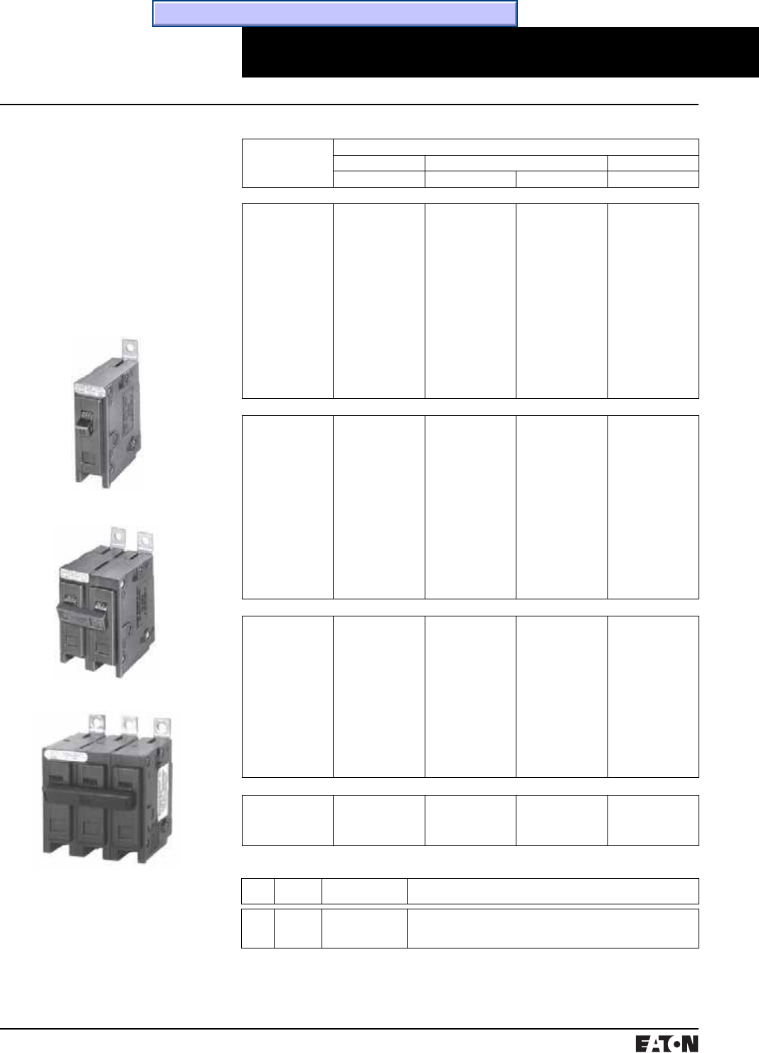
Miniature Circuit Breakers
QUICKLAG Industrial Circuit Breakers
QUICKLAG Industrial Circuit Breakers Plug-on
Description
Built and Listed to UL 489
QUICKLAG Circuit Breakers
Plug-on Type
Type HQP: 10-150 Amperes,
10,000 AIC
Type QPHW: 15-125 Amperes,
22,000 AIC
Type QHPX: 15-100 Amperes,
42,000 AIC
Type QHPW: 15-30 Amperes,
65,000 AIC
Breaker Catalog Numbers
Continuous Ampere
Rating at
40°C
Catalog Number
1-Pole➀➁ 2-Pole➀➁ 3-Pole➀➁
120/240 Vac 120/240 Vac 240 Vac 240 Vac
QUICKLAG Type: HQP 10,000 Ampere I.C. Thermal-Magnetic Breakers
10
15
20
25
30
35
40
45
50
55
60
70
80
90
100
110
125
150
HQP1010
HQP1015➂➃
HQP1020➂➃
HQP1025
HQP1030
HQP1035
HQP1040
HQP1045
HQP1050
HQP1055
HQP1060
HQP1070
–
–
HQP1100
–
–
–
HQP2010
HQP2015
HQP2020
HQP2025
HQP2030
HQP2035
HQP2040
HQP2045
HQP2050
HQP2055
HQP2060
HQP2070
HQP2080
HQP2090
HQP2100
HQP2110
HQP2125
HQP2150
HQP2010H
HQP2015H
HQP2020H
HQP2025H
HQP2030H
HQP2035H
HQP2040H
HQP2045H
HQP2050H
HQP2055H
HQP2060H
HQP2070H
HQP2080H
HQP2090H
HQP2100H
–
–
–
HQP3010H
HQP3015H
HQP3020H
HQP3025H
HQP3030H
HQP3035H
HQP3040H
HQP3045H
HQP3050H
HQP3055H
HQP3060H
HQP3070H
HQP3080H
HQP3090H
HQP3100H
–
–
–
QUICKLAG Type: QPHW 22,000 Ampere I.C. Thermal-Magnetic Breakers
15
20
25
30
35
40
45
50
55
60
70
80
90
100
110
125
QPHW1015➂
QPHW1020➂
QPHW1025
QPHW1030
QPHW1035
QPHW1040
QPHW1045
QPHW1050
QPHW1055
QPHW1060
QPHW1070
–
–
–
–
–
QPHW2015
QPHW2020
QPHW2025
QPHW2030
QPHW2035
QPHW2040
QPHW2045
QPHW2050
QPHW2055
QPHW2060
QPHW2070
QPHW2080
QPHW2090
QPHW2100
QPHW2110
QPHW2125
QPHW2015H
QPHW2020H
QPHW2025H
QPHW2030H
QPHW2035H
QPHW2040H
QPHW2045H
QPHW2050H
QPHW2055H
QPHW2060H
QPHW2070H
QPHW2080H
QPHW2090H
QPHW2100H
–
–
QPHW3015H
QPHW3020H
QPHW3025H
QPHW3030H
QPHW3035H
QPHW3040H
QPHW3045H
QPHW3050H
QPHW3055H
QPHW3060H
QPHW3070H
QPHW3080H
QPHW3090H
QPHW3100H
–
–
QUICKLAG Type: QHPX 42,000 Ampere I.C. Thermal-Magnetic Breakers
15
20
25
30
35
40
45
50
55
60
70
80
90
100
QHPX1015➂
QHPX1020➂
QHPX1025
QHPX1030
QHPX1035
QHPX1040
QHPX1045
QHPX1050
QHPX1055
QHPX1060
QHPX1070
–
–
–
QHPX2015
QHPX2020
QHPX2025
QHPX2030
QHPX2035
QHPX2040
QHPX2045
QHPX2050
QHPX2055
QHPX2060
QHPX2070
QHPX2080
QHPX2090
QHPX2100
–
–
–
–
–
–
–
–
–
–
–
–
–
–
QHPX3015H
QHPX3020H
QHPX3025H
QHPX3030H
QHPX3035H
QHPX3040H
QHPX3045H
QHPX3050H
QHPX3055H
QHPX3060H
QHPX3070H
QHPX3080H
QHPX3090H
QHPX3100H
QUICKLAG Type: QHPW 65,000 Ampere I.C. Thermal-Magnetic Breakers
15
20
25
30
QHPW1015➂
QHPW1020➂
QHPW1025
QHPW1030
QHPW2015
QHPW2020
QHPW2025
QHPW2030
–
–
–
–
QHPW3015H
QHPW3020H
–
–
Shipping Data
Poles Carton
Quantity
Approximate
Weight Lbs. (Kgs)
Dimensions
Inches (mm)
1
2
3
24
12
8
9.000 (4.09)
9.000 (4.09)
9.000 (4.09)
12.500 (317.50) x 7.500 (190.50) x 5.000 (127.00)
12.500 (317.50) x 7.500 (190.50) x 5.000 (127.00)
12.500 (317.50) x 7.500 (190.50) x 5.000 (127.00)
QUICKLAG Type HQP 1-Pole
QUICKLAG Type HQP 2-Pole
QUICKLAG Type HQP 3-Pole
➀All products UL and CSA listed.
➁All products 15-100A are HACR rated.
➂Switching duty rated for 120 Vac
fluorescent light applications.
➃For special low-magnetic breaker order
HQP1015L1 or HQP1020L1
Time/Current Curves, Dimension Sheets, Application Data

PG.74A.01.T.E
Cutler-Hammer
6March 1999
Miniature Circuit Breakers
QUICKLAG Industrial Circuit Breakers
QUICKLAG Industrial Ground Fault Circuit Breakers and Equipment Protectors Plug-on
Description
Plug-on Type
Built and Listed to UL 489
QUICKLAG Ground Fault Circuit
Breakers, Class A GFCI
Built and Tested to UL 943
5mA Trip Sensitivity
Type QPGF: 15-50 Amperes,
10,000 AIC
Type QPHGF: 15-30 Amperes,
22,000 AIC
QUICKLAG Ground Fault Equipment
Protectors
Built and Listed to UL 1053
30mA Trip Sensitivity
Type QPGFEP: 15-50 Amperes,
10,000 AIC
Type QPHGFEP: 15-30 Amperes,
22,000 AIC
QUICKLAG Type QPGF 1-Pole
Ground Fault Circuit Breaker
QUICKLAG Type QPGF 2-Pole
Ground Fault Circuit Breaker
Shipping Data
Shipped individually or in carton
quantities.
Poles Carton
Quantity
Approximate
Weight Lbs. (Kgs)
Dimensions
Inches (mm)
1
2
20
5
11.000 (4.99)
5.000 (2.29)
12.500 (317.50) x
6.500 (165.10) x
5.000 (127.00)
15.500 (393.70) x
6.000 (152.40) x
4.500 (114.30)
Blue Wire
Red Wire
Black Wire
Ground
Fault
Breaker
Single-throw double-pole contacts are UL and CSA listed for 5 Amperes at 250 Vac.
Bell Alarm (W1) – contacts change state when breaker trips.
Auxiliary Switch (W2) – contacts change state when breaker is opened (or tripped) or closed.
14-inch long #18 AWG pigtail wire leads provided.
Bell Alarm and Auxiliary Contact Schematic
Blue
Red
NC
NO
Breaker Catalog Numbers
Continuous
Ampere
Rating at
40°C
Catalog Number
1-Pole 2-Pole
120 Vac 120/240 Vac
Ground Fault Circuit Breakers – 5mA Sensitivity
QUICKLAG Type: QPGF 10,000 Ampere I.C. Thermal-Magnetic Breakers
15
20
25
30
40
50
QPGF1015
QPGF1020
QPGF1025
QPGF1030
QPGF1040
–
QPGF2015
QPGF2020
QPGF2025
QPGF2030
QPGF2040
QPGF2050
QUICKLAG Type: QPHGF 22,000 Ampere I.C. Thermal-Magnetic Breakers
15
20
25
30
QPHGF1015
QPHGF1020
QPHGF1025
QPHGF1030
QPHGF2015
QPHGF2020
QPHGF2025
QPHGF2030
Ground Fault Equipment Protectors – 30mA Sensitivity
QUICKLAG Type: QPGFEP 10,000 Ampere I.C. Thermal-Magnetic Breakers
15
20
25
30
40
50
QPGFEP1015
QPGFEP1020
QPGFEP1025
QPGFEP1030
QPGFEP1040
–
QPGFEP2015
QPGFEP2020
QPGFEP2025
QPGFEP2030
QPGFEP2040
QPGFEP2050
QUICKLAG Type: QPHGFEP 22,000 Ampere I.C. Thermal-Magnetic Breakers
15
20
25
30
QPHGFEP1015
QPHGFEP1020
QPHGFEP1025
QPHGFEP1030
QPHGFEP2015
QPHGFEP2020
QPHGHEP2025
QPHGFEP2030
Special Application Ground Fault Circuit Protectors – 5mA Sensitivity
QUICKLAG Type: QPGF 10,000 Ampere I.C. with Bell Alarm (W1) or Auxiliary Switch (W2)
15
20
25
30
40
50
QPGF1015W1
QPGF1020W1
QPGF1025W1
QPGF1030W1
–
–
QPGF2015W1
QPGF2020W1
QPGF2025W1
QPGF2030W1
QPGF2040W1
QPGF2050W1
15
20
25
30
QPGF1015W2
QPGF1020W2
QPGF1025W2
QPGF1030W2
–
–
–
–
Special Application Ground Fault Circuit Protectors – 30mA Sensitivity
QUICKLAG Type: QPGFEP 10,000 Ampere I.C. with Bell Alarm (W1) or Auxiliary Switch (W2)
15
20
25
30
40
50
QPGFEP1015W1
QPGFEP1020W1
QPGFEP1025W1
QPGFEP1030W1
–
–
QPGFEP2015W1
QPGFEP2020W1
QPGFEP2025W1
QPGFEP2030W1
QPGFEP2040W1
QPGFEP2050W1
15
20
25
30
QPGFEP1015W2
QPGFEP1020W2
QPGFEP1025W2
QPGFEP1030W2
–
–
–
–
Time/Current Curves, Dimension Sheets, Application Data
March 1999
PG.74A.01.T.E
Cutler-Hammer 7
Miniature Circuit Breakers
QUICKLAG Industrial Circuit Breakers
QUICKLAG Industrial Circuit Breakers Bolt-on
Description
Built and Listed to UL 489
QUICKLAG Circuit Breakers
Bolt-on Type
Type BA: 10-125 Amperes,
10,000 AIC
Type QBHW: 15-125 Amperes,
22,000 AIC
Type HBAX: 15-100 Amperes,
42,000 AIC
Type HBAW: 15-30 Amperes,
65,000 AIC
QUICKLAG Type BA 1-Pole
QUICKLAG
Type BA 3-Pole
QUICKLAG Type BA 2-Pole
Breaker Catalog Numbers
Continuous
Ampere
Rating at
40°C
Catalog Number
1-Pole➀➁ 2-Pole➀➁ 3-Pole➀➁
120/240 Vac 120/240 Vac 240 Vac 240 Vac
QUICKLAG Type: BA 10,000 Ampere I.C. Thermal-Magnetic Breakers
10
15
20
25
30
35
40
45
50
55
60
70
80
90
100
110
125
BAB1010
BAB1015➂➃
BAB1020➂➃
BAB1025
BAB1030
BAB1035
BAB1040
BAB1045
BAB1050
BAB1055
BAB1060
BAB1070
–
–
BAB1100
–
–
BAB2010
BAB2015
BAB2020
BAB2025
BAB2030
BAB2035
BAB2040
BAB2045
BAB2050
BAB2055
BAB2060
BAB2070
BAB2080
BAB2090
BAB2100
BAB2110
BAB2125
BAB2010H
BAB2015H
BAB2020H
BAB2025H
BAB2030H
BAB2035H
BAB2040H
BAB2045H
BAB2050H
BAB2055H
BAB2060H
BAB2070H
BAB2080H
BAB2090H
BAB2100H
–
–
BAB3010H
BAB3015H
BAB3020H
BAB3025H
BAB3030H
BAB3035H
BAB3040H
BAB3045H
BAB3050H
BAB3055H
BAB3060H
BAB3070H
BAB3080H
BAB3090H
BAB3100H
–
–
QUICKLAG Type: QBHW 22,000 Ampere I.C. Thermal-Magnetic Breakers
15
20
25
30
35
40
45
50
55
60
70
80
90
100
110
125
QBHW1015➂
QBHW1020➂
QBHW1025
QBHW1030
QBHW1035
QBHW1040
QBHW1045
QBHW1050
QBHW1055
QBHW1060
QBHW1070
–
–
–
–
–
QBHW2015
QBHW2020
QBHW2025
QBHW2030
QBHW2035
QBHW2040
QBHW2045
QBHW2050
QBHW2055
QBHW2060
QBHW2070
QBHW2080
QBHW2090
QBHW2100
QBHW2110
QBHW2125
QBHW2015H
QBHW2020H
QBHW2025H
QBHW2030H
QBHW2035H
QBHW2040H
QBHW2045H
QBHW2050H
QBHW2055H
QBHW2060H
QBHW2070H
QBHW2080H
QBHW2090H
QBHW2100H
–
–
QBHW3015H
QBHW3020H
QBHW3025H
QBHW3030H
QBHW3035H
QBHW3040H
QBHW3045H
QBHW3050H
QBHW3055H
QBHW3060H
QBHW3070H
QBHW3080H
QBHW3090H
QBHW3100H
–
–
QUICKLAG Type: HBAX 42,000 Ampere I.C. Thermal-Magnetic Breakers
15
20
25
30
35
40
45
50
55
60
70
80
90
100
HBAX1015➂
HBAX1020➂
HBAX1025
HBAX1030
HBAX1035
HBAX1040
HBAX1045
HBAX1050
HBAX1055
HBAX1060
HBAX1070
–
–
–
HBAX2015
HBAX2020
HBAX2025
HBAX2030
HBAX2035
HBAX2040
HBAX2045
HBAX2050
HBAX2055
HBAX2060
HBAX2070
HBAX2080
HBAX2090
HBAX2100
–
–
–
–
–
–
–
–
–
–
–
–
–
–
HBAX3015H
HBAX3020H
HBAX3025H
HBAX3030H
HBAX3035H
HBAX3040H
HBAX3045H
HBAX3050H
HBAX3055H
HBAX3060H
HBAX3070H
HBAX3080H
HBAX3090H
HBAX3100H
QUICKLAG Type: HBAW 65,000 Ampere I.C. Thermal-Magnetic Breakers
15
20
25
30
HBAW1015➂
HBAW1020➂
HBAW1025
HBAW1030
HBAW2015
HBAW2020
HBAW2025
HBAW2030
–
–
–
–
HBAW3015H
HBAW3020H
–
–
Shipping Data
Poles Carton
Quantity
Approximate
Weight Lbs. (Kgs)
Dimensions Inches (mm)
1
2
3
24
18
8
9.000 (4.09)
9.000 (4.09)
9.000 (4.09)
12.500 (317.50) x 7.500 (190.50) x 5.000 (127.00)
12.500 (317.50) x 7.500 (190.50) x 5.000 (127.00)
12.500 (317.50) x 7.500 (190.50) x 5.000 (127.00)
➀All products UL and CSA listed.
➁All products 15-100A are HACR rated.
➂Switching duty rated for 120 Vac
fluorescent light applications.
➃For special low-magnetic breaker order
BAB1015L1 or BAB1020L1.
Time/Current Curves, Dimension Sheets, Application Data

PG.74A.01.T.E
Cutler-Hammer
8March 1999
Miniature Circuit Breakers
QUICKLAG Industrial Circuit Breakers
QUICKLAG Industrial Ground Fault Circuit Protectors Bolt-on
Description
Bolt-on Type
Built and Listed to UL 489
QUICKLAG Ground Fault Circuit
Breakers, Class A GFCI
Built and Tested to UL 943
5mA Trip Sensitivity
Type QBGF: 15-50 Amperes,
10,000 AIC
Type QBHGF: 15-30 Amperes,
22,000 AIC
QUICKLAG Ground Fault
Equipment Protectors
Built and Tested to UL 1053
30mA Trip Sensitivity
Type QBGFEP: 15-50 Amperes,
10,000 AIC
Type QBHGFEP: 15-30 Amperes,
22,000 AIC
QUICKLAG Type QBGF 1-Pole
Ground Fault Circuit Breaker
QUICKLAG Type QBGF 2-Pole
Ground Fault Circuit Breaker
Breaker Catalog Numbers
Continuous
Ampere
Rating at
40°C
Catalog Number
1-Pole 2-Pole
120 Vac 120/240 Vac
Ground Fault Circuit Breakers – 5mA Sensitivity
QUICKLAG Type: QBGF 10,000 Ampere I.C. Thermal-Magnetic Breakers
15
20
25
30
40
50
QBGF1015
QBGF1020
QBGF1025
QBGF1030
QBGF1040
–
QBGF2015
QBGF2020
QBGF2025
QBGF2030
QBGF2040
QBGF2050
QUICKLAG Type: QBHGF 22,000 Ampere I.C. Thermal-Magnetic Breakers
15
20
25
30
QBHGF1015
QBHGF1020
QBHGF1025
QBHGF1030
QBHGF2015
QBHGF2020
QBHGF2025
QBHGF2030
Ground Fault Equipment Protectors – 30mA Sensitivity
QUICKLAG Type: QBGFEP 10,000 Ampere I.C. Thermal-Magnetic Breakers
15
20
25
30
40
50
QBGFEP1015
QBGFEP1020
QBGFEP1025
QBGFEP1030
QBGFEP1040
–
QBGFEP2015
QBGFEP2020
QBGFEP2025
QBGFEP2030
QBGFEP2040
QBGFEP2050
QUICKLAG Type: QBHGFEP 22,000 Ampere I.C. Thermal-Magnetic Breakers
15
20
25
30
QBHGFEP1015
QBHGFEP1020
QBHGFEP1025
QBHGFEP1030
QBHGFEP2015
QBHGFEP2020
QBHGFEP2025
QBHGFEP2030
Special Application Ground Fault Circuit Protectors – 5mA Sensitivity
QUICKLAG Type: QBGF 10,000 Ampere I.C. with Bell Alarm (W1) or Auxiliary Switch (W2)
15
20
25
30
40
50
QBGF1015W1
QBGF1020W1
QBGF1025W1
QBGF1030W1
–
–
QBGF2015W1
QBGF2020W1
QBGF2025W1
QBGF2030W1
QBGF2040W1
QBGF2050W1
15
20
25
30
QBGF1015W2
QBGF1020W2
QBGF1025W2
QBGF1030W2
–
–
–
–
Special Application Ground Fault Circuit Protectors – 30mA Sensitivity
QUICKLAG Type: QBGFEP 10,000 Ampere I.C. with Bell Alarm (W1) or Auxiliary Switch (W2)
15
20
25
30
40
50
QBGFEP1015W1
QBGFEP1020W1
QBGFEP1025W1
QBGFEP1030W1
–
–
QBGFEP2015W1
QBGFEP2020W1
QBGFEP2025W1
QBGFEP2030W1
QBGFEP2040W1
QBGFEP2050W1
15
20
25
30
QBGFEP1015W2
QBGFEP1020W2
QBGFEP1025W2
QBGFEP1030W2
–
–
–
–
Shipping Data
Poles Carton
Quantity
Approximate
Weight Lbs.
(Kgs)
Dimensions
Inches (mm)
1
2
20
5
11.000 (4.99)
5.000 (2.29)
12.500 (317.50)
x 6.500 (165.10)
x 5.000 (127.00)
15.500 (393.70)
x 6.000 (152.40)
x 4.500 (114.30)
Blue Wire
Red Wire
Black Wire
Ground
Fault
Breaker
Single-throw double-pole contacts are UL and CSA listed for 5 Amperes at 250 Vac.
Bell Alarm (W1) – contacts change state when breaker trips.
Auxiliary Switch (W2) – contacts change state when breaker is opened (or tripped) or closed.
14-inch long #18 AWG pigtail wire leads provided.
Bell Alarm and Auxiliary Contact Schematic
Blue
Red
NC
NO
Time/Current Curves, Dimension Sheets, Application Data

March 1999
PG.74A.01.T.E
Cutler-Hammer 9
Miniature Circuit Breakers
QUICKLAG Industrial Circuit Breakers
QUICKLAG Industrial Circuit Breakers Cable-in/Cable-out (1 inch per pole)
Breaker Catalog Numbers
Continuous
Ampere
Rating at
40°C
Catalog Number
1-Pole➀➁ 2-Pole➀➁ 3-Pole➀➁ 4-Pole➀➁
120/240 Vac 120/240 Vac 240 Vac 240 Vac 240 Vac
QUICKLAG Type: QC 10,000 Ampere I.C. Thermal-Magnetic Breakers
10
15
20
25
30
35
40
45
50
55
60
70
80
90
100
QC1010
QC1015➂➃
QC1020➂➃
QC1025
QC1030
QC1035
QC1040
QC1045
QC1050
QC1055
QC1060
QC1070
–
–
QC1100
QC2010
QC2015
QC2020
QC2025
QC2030
QC2035
QC2040
QC2045
QC2050
QC2055
QC2060
QC2070
QC2080
QC2090
QC2100
QC2010H
QC2015H
QC2020H
QC2025H
QC2030H
QC2035H
QC2040H
QC2045H
QC2050H
QC2055H
QC2060H
QC2070H
QC2080H
QC2090H
QC2100H
QC3010H
QC3015H
QC3020H
QC3025H
QC3030H
QC3035H
QC3040H
QC3045H
QC3050H
QC3055H
QC3060H
QC3070H
QC3080H
QC3090H
QC3100H
QC4010H
QC4015H
QC4020H
QC4025H
QC4030H
QC4035H
QC4040H
QC4045H
QC4050H
QC4055H
QC4060H
QC4070H
QC4080H
QC4090H
QC4100H
QUICKLAG Type: QCHW 22,000 Ampere I.C. Thermal-Magnetic Breakers
15
20
25
30
35
40
45
50
55
60
70
80
90
100
QCHW1015➂
QCHW1020➂
QCHW1025
QCHW1030
QCHW1035
QCHW1040
QCHW1045
QCHW1050
QCHW1055
QCHW1060
QCHW1070
–
–
–
QCHW2015
QCHW2020
QCHW2025
QCHW2030
QCHW2035
QCHW2040
QCHW2045
QCHW2050
QCHW2055
QCHW2060
QCHW2070
QCHW2080
QCHW2090
QCHW2100
QCHW2015H
QCHW2020H
QCHW2025H
QCHW2030H
QCHW2035H
QCHW2040H
QCHW2045H
QCHW2050H
QCHW2055H
QCHW2060H
QCHW2070H
QCHW2080H
QCHW2090H
QCHW2100H
QCHW3015H
QCHW3020H
QCHW3025H
QCHW3030H
QCHW3035H
QCHW3040H
QCHW3045H
QCHW3050H
QCHW3055H
QCHW3060H
QCHW3070H
QCHW3080H
QCHW3090H
QCHW3100H
QCHW4015H
QCHW4020H
QCHW4025H
QCHW4030H
QCHW4035H
QCHW4040H
QCHW4045H
QCHW4050H
QCHW4055H
QCHW4060H
QCHW4070H
QCHW4080H
QCHW4090H
QCHW4100H
QUICKLAG Type: QHCX 42,000 Ampere I.C. Thermal-Magnetic Breakers
15
20
25
30
35
40
45
50
55
60
70
80
90
100
QHCX1015➂
QHCX1020➂
QHCX1025
QHCX1030
QHCX1035
QHCX1040
QHCX1045
QHCX1050
QHCX1055
QHCX1060
QHCX1070
–
–
–
QHCX2015
QHCX2020
QHCX2025
QHCX2030
QHCX2035
QHCX2040
QHCX2045
QHCX2050
QHCX2055
QHCX2060
QHCX2070
QHCX2080
QHCX2090
QHCX2100
–
–
–
–
–
–
–
–
–
–
–
–
–
–
QHCX3015H
QHCX3020H
QHCX3025H
QHCX3030H
QHCX3035H
QHCX3040H
QHCX3045H
QHCX3050H
QHCX3055H
QHCX3060H
QHCX3070H
QHCX3080H
QHCX3090H
QHCX3100H
–
–
–
–
–
–
–
–
–
–
–
–
–
–
QUICKLAG Type: QHCW 65,000 Ampere I.C. Thermal-Magnetic Breakers
15
20
25
30
QHCW1015➂
QHCW1020➂
QHCW1025
QHCW1030
QHCW2015
QHCW2020
QHCW2025
QHCW2030
–
–
–
–
QHCW3015H
QHCW3020H
–
–
–
–
–
–
QUICKLAG Type QC 4-Pole
Description
Built and Listed to UL 489
QUICKLAG Circuit Breakers
Cable-in/Cable-out Type
Type QC: 10-100 Amperes,
10,000 AIC
Type QCHW: 15-100 Amperes,
22,000 AIC
Type QHCX: 15-100 Amperes,
42,000 AIC
Type QHCW: 15-30 Amperes,
65,000 AIC
QUICKLAG Type QC 1-Pole
QUICKLAG Type QC 3-Pole
➀All products UL and CSA listed.
➁All products 10-100A are HACR rated.
➂Switching duty rated for 120 Vac
fluorescent light applications only.
➃For special low-magnetic breaker order
QC1015L1 or QC1020L1.
Shipping Data
Poles Carton
Quantity
Approximate
Weight Lbs. (Kgs)
Dimensions Inches (mm)
1
2
3
24
18
8
9.000 (4.09)
9.000 (4.09)
9.000 (4.09)
12.500 (317.50) x 7.500 (190.50) x 5.000 (127.00)
12.500 (317.50) x 7.500 (190.50) x 5.000 (127.00)
12.500 (317.50) x 7.500 (190.50) x 5.000 (127.00)
Time/Current Curves, Dimension Sheets, Application Data
PG.74A.01.T.E
Cutler-Hammer
10 March 1999
Miniature Circuit Breakers
QUICKLAG Industrial Circuit Breakers
QUICKLAG Industrial Circuit Breakers Cable-in/Cable-out (1/2 inch per pole)
Description
Built and Listed to UL 489
Type QCR and QCF Circuit Breakers
are UL listed Circuit Breakers that
are suitable for use as branch circuit
protectors.
Applications
QCR and QCF Circuit Breakers are
only 1/2-inch wide per pole and
are excellent for general purpose
industrial applications where space
savings is required.
Product Features and Ratings
■1/2-inch wide per pole
■Cable-in/Cable-out
■Black cases with black handles
■Three position handle: ON,
Tripped (center), OFF
■Thermal-Magnetic Protection
■UL File E7819
■CSA File LR48907
■One, two and three pole
■10 kAIC at 120/240 Vac,
10-60 Amperes
■22 kAIC at 120/240 Vac,
15-20 Amperes
■10 kAIC at 240 Vac, 10-30 Amperes
■3 kAIC at 62.5 Vdc (1 Pole)
■3 kAIC at 130 Vdc (2 Poles
in Series)
■Normal Operating Environment:
0-40°C
5-95% Humidity
(Non-Condensating)
Additional Ratings
In addition to the ratings shown for
the 1/2-inch wide QCR and QCF, the
complete QC breaker line includes:
■1-4 Poles
■5-100 Amperes
■10 through 65 kAIC
■120/240 and 240 Vac
■1-inch per pole
QCR (Rear-Mounted Breakers) QCF (Front-Mounted Breakers)
1-Pole 2-Pole 1-Pole 2-Pole
Type QCF have two threaded steel
inserts to facilitate front mounting
with #6-32 steel screws. The clamp
type terminals accessible from the
rear of the breaker so that cables can
be accessed without removal of the
breaker from the front cover.
Type QCR have as a standard feature
provisions for 35mm DIN-Rail rear
mounting with a spring-loaded
release. Optional clips for individual
mounting are available as a separate
accessory.
QCR 1-Pole Breaker with QCRMTGFT
Clips (Qty. 2) Individually Mounted
QCF Breaker Front Panel Mounted
QCR (Rear-Mounted Breakers)
3-Pole
QCF (Front-Mounted Breakers)
3-Pole

March 1999
PG.74A.01.T.E
Cutler-Hammer 11
Miniature Circuit Breakers
QUICKLAG Industrial Circuit Breakers
QUICKLAG Industrial Circuit Breakers Cable-in/Cable-out (1/2 inch per pole)
Breaker Catalog Numbers➀➁➂➃
Continuous
Ampere
Rating at
40°C
QCR Breaker 10 kAIC Interruption Ratings➄QCF Breaker 10 kAIC Interruption Ratings➄
120/240 Vac 120/240 Vac 240 Vac➅120/240 Vac 120/240 Vac 240 Vac➅
1-Pole 2-Pole 2-Pole 3-Pole 1-Pole 2-Pole 2-Pole 3-Pole
QCR Breaker 10 kAIC Interruption Ratings➄QCF Breaker 10 kAIC Interruption Ratings➄
10 QCR1010
QCR1010T
–
QCR2010
QCR2010T
QCR2010P
–
–
–
–
–
–
QCF1010
QCF1010T
–
QCF2010
QCF2010T
–
–
–
–
–
–
–
15 QCR1015➆
QCR1015T➆
–
QCR2015
QCR2015T
QCR2015P
QCR2015H
QCR2015HT
–
QCR3015H
QCR3015HT
–
QCF1015➁
QCF1015T➁
–
QCF2015
QCF2015T
–
QCF2015H
QCF2015HT
–
QCF3015H
QCF3015HT
–
20 QCR1020➆
QCR1020T➆
–
QCR2020
QCR2020T
QCR2020P
QCR2020H
QCR2020HT
–
QCR3020H
QCR3020HT
–
QCF1020➁
QCF1020T➁
–
QCF2020
QCF2020T
–
QCF2020H
QCF2020HT
–
QCF3020H
QCF3020HT
–
25 QCR1025
QCR1025T
–
QCR2025
QCR2025T
QCR2025P
QCR2025H
QCR2025HT
–
QCR3025H
QCR3025HT
–
QCF1025
QCF1025T
–
QCF2025
QCF2025T
–
QCF2025H
QCF2025HT
–
QCF3025H
QCF3025HT
–
30 QCR1030
QCR1030T
–
QCR2030
QCR2030T
QCR2030P
QCR2030H
QCR2030HT
–
QCR3030H
QCR3030HT
–
QCF1030
QCF1030T
–
QCF2030
QCF2030T
–
QCF2030H
QCF2030HT
–
QCF3030H
QCF3030HT
–
35 QCR1035
–
QCR2035
QCR2035P
–
–
–
–
QCF1035
–
QCF2035
–
–
–
–
–
40 QCR1040
–
QCR2040
QCR2040P
–
–
–
–
QCF1040
–
QCF2040
–
–
–
–
–
45 QCR1045
–
QCR2045
QCR2045P
–
–
–
–
QCF1045
–
QCF2045
–
–
–
–
–
50 QCR1050
–
QCR2050
QCR2050P
–
–
–
–
QCF1050
–
QCF2050
–
–
–
–
–
55 QCR1055
–
QCR2055
QCR2055P
–
–
–
–
QCF1055
–
QCF2055
–
–
–
–
–
60➇QCR1060
–
QCR2060
QCR2060P
–
–
–
–
QCF1060
–
QCF2060
–
–
–
–
–
QCR Breaker 22 kAIC Interruption Ratings QCF Breaker 22 kAIC Interruption Ratings
15 QCRH1015➆
QCRH1015T➆
QCRH2015
QCRH2015T
–
–
–
–
QCFH1015➆
QCFH1015T➆
QCFH2015
QCFH2015T
–
–
–
–
20 QCRH1020➆
QCRH1020T➆
QCRH2020
QCRH2020T
–
–
–
–
QCFH1020➆
QCFH1020T➆
QCFH2020
QCFH2020T
–
–
–
–
Available QCR and QCF Breaker Accessories
Catalog Number Description
QCRMTGFT Steel mounting clip mounts QCR breaker if individual mounting is required. Quantity two required for 1- and 2-pole and four required
for 3-pole breakers.
QCRFPL1P Removable padlock device for single-pole QCR or QCF breaker.
QCRFPLMP Removable padlock device for multi-pole QCR or QCF breaker.
QCRFLOFF Padlock bracket assembly for QCR or QCF single or multi-pole breakers (off only).
➀Standard breaker terminals are box type
lugs.
➁Breakers with “T” Catalog Number Suffix are
suitable for line and load side ring terminal
connection (#10-32 plus/minus terminal
screw provided).
➂Breakers with “P” Catalog Number Suffix are
suitable for terminating 2 #10 AWG Quick-
Connect Type Terminals per phase on
breaker load side.
➃Breakers with Shunt Trip Attachment (extra
pole required on breaker right-hand side) are
available. Contact Cutler-Hammer.
➄All ratings 15 to 60 amperes are HACR rated.
➅Breakers with “H” Catalog Suffix have
240 Vac construction.
➆All 15 and 20 ampere single-pole breakers
are SWD (Switching Duty) rated for fluores-
cent lighting applications.
➇60/75°C Cu/Al wire on all ratings except 60
amperes which requires Cu only conductor.
Time/Current Curves, Dimension Sheets, Application Data

PG.74A.01.T.E
Cutler-Hammer
12 March 1999
Miniature Circuit Breakers
QUICKLAG Industrial Circuit Breakers
QUICKLAG Industrial Circuit Breakers Cable-in/Cable-out (1/2 inch per pole)
QCR and QCF Breaker Factory Installed Terminals
Catalog Suffix “P”
Catalog Suffix “T”
QCR and QCF Standard Box Terminals
Factory installed line and load side
breaker terminal to accommodate
#14 AWG to #4 AWG wire.
QCR Quick-Connect Terminals
Factory installed two-prong quick-
connect terminal on breaker load
side suitable for terminating two
#10 AWG wire with insulated slip-on
terminals as shown. Line side term-
inal is the standard type.
QCR and QCF Ring or
Spade Lug Terminals
(10 to 30 ampere ratings only):
Factory installed line and load side
terminals each equipped with a
#10-32 screw suitable for terminating
one #10 AWG wire with insulated
ring or spade type terminal as shown.

March 1999
PG.74A.01.T.E
Cutler-Hammer 13
Miniature Circuit Breakers
QUICKLAG Industrial Circuit Breakers
QUICKLAG Industrial Ground Fault Circuit Breakers and Equipment Protectors Cable-in/Cable-out
Description
Cable-in/Cable-out Type
Built and Listed to UL 489
QUICKLAG Ground Fault
Circuit Breakers, Class A GFCI
Built and Tested to UL 943
5mA Trip Sensitivity
Type QCGF: 15-50 Amperes,
10,000 AIC
Type QCHGF: 15-30 Amperes,
22,000 AIC
QUICKLAG Ground Fault
Equipment Protectors
Built and Tested to UL 1053
30mA Trip Sensitivity
Type QCGFEP: 15-50 Amperes,
10,000 AIC
Type QCHGFEP: 15-30 Amperes,
22,000 AIC
QUICKLAG Type QCGF 1-Pole
Ground Fault Circuit Breaker
QUICKLAG Type QCGF 2-Pole
Ground Fault Circuit Breaker
Breaker Catalog Numbers
Continuous
Ampere
Rating at
40°C
Catalog Number
1-Pole➀2-Pole➀
120 Vac 120/240 Vac
Ground Fault Circuit Breakers – 5mA Sensitivity
QUICKLAG Type: QCGF 10,000 Ampere I.C. Thermal-Magnetic Breakers
15
20
25
30
40
50
QCGF1015
QCGF1020
QCGF1025
QCGF1030
QCGF1040
–
QCGF2015
QCGF2020
QCGF2025
QCGF2030
QCGF2040
QCGF2050
QUICKLAG Type: QCHGF 22,000 Ampere I.C. Thermal-Magnetic Breakers
15
20
25
30
QCHGF1015
QCHGF1020
QCHGF1025
QCHGF1030
QCHGF2015
QCHGF2020
QCHGF2025
QCHGF2030
Ground Fault Equipment Protectors – 30mA Sensitivity
QUICKLAG Type: QCGFEP 10,000 Ampere I.C. Thermal-Magnetic Breakers
15
20
25
30
40
50
QCGFEP1015
QCGFEP1020
QCGFEP1025
QCGFEP1030
QCGFEP1040
–
QCGFEP2015
QCGFEP2020
QCGFEP2025
QCGFEP2030
QCGFEP2040
QCGFEP2050
QUICKLAG Type: QCHGFEP 22,000 Ampere I.C. Thermal-Magnetic Breakers
15
20
25
30
QCHGFEP1015
QCHGFEP1020
QCHGFEP1025
QCHGFEP1030
QCHGFEP2015
QCHGFEP2020
QCHGFEP2025
QCHGFEP2030
Special Application Ground Fault Circuit Protector – 5mA Sensitivity
QUICKLAG Type: QCGF 10,000 Ampere I.C. with Bell Alarm (W1) or Auxiliary Switch (W2)
15
20
25
30
40
50
QCGF1015W1
QCGF1020W1
QCGF1025W1
QCGF1030W1
–
–
QCGF2015W1
QCGF2020W1
QCGF2025W1
QCGF2030W1
QCGF2040W1
QCGF2050W1
15
20
25
30
QCGF1015W2
QCGF1020W2
QCGF1025W2
QCGF1030W2
–
–
–
–
Special Application Ground Fault Equipment Protectors – 30mA Sensitivity
QUICKLAG Type: QCGFEP 10,000 Ampere I.C. with Bell Alarm (W1) or Auxiliary Switch (W2)
15
20
25
30
40
50
QCGFEP1015W1
QCGFEP1020W1
QCGFEP1025W1
QCGFEP1030W1
–
–
QCGFEP2015W1
QCGFEP2020W1
QCGFEP2025W1
QCGFEP2030W1
QCGFEP2040W1
QCGFEP2050W1
15
20
25
30
QCGFEP1015W2
QCGFEP1020W2
QCGFEP1025W2
QCGFEP1030W2
–
–
–
–
Blue Wire
Red Wire
Black Wire
Ground
Fault
Breaker
Single-throw double-pole contacts are UL and CSA listed for 5 Amperes at 250 Vac.
Bell Alarm (W1) – contacts change state when breaker trips.
Auxiliary Switch (W2) – contacts change state when breaker is opened (or tripped) or closed.
14-inch long #18 AWG pigtail wire leads provided.
Bell Alarm and Auxiliary Contact Schematic
Blue
Red
NC
NO
➀All products UL and CSA listed.
Shipping Data
Poles Carton
Quantity
Approximate
Weight Lbs.
(Kgs)
Dimensions
Inches (mm)
1
2
20
5
11.000 (4.99)
5.000 (2.29)
12.500 (317.50) x
6.500 (165.10) x
5.000 (127.00)
15.500 (393.70) x
6.000 (152.40) x
4.500 (114.30)
Time/Current Curves, Dimension Sheets, Application Data
PG.74A.01.T.E
Cutler-Hammer
14 March 1999
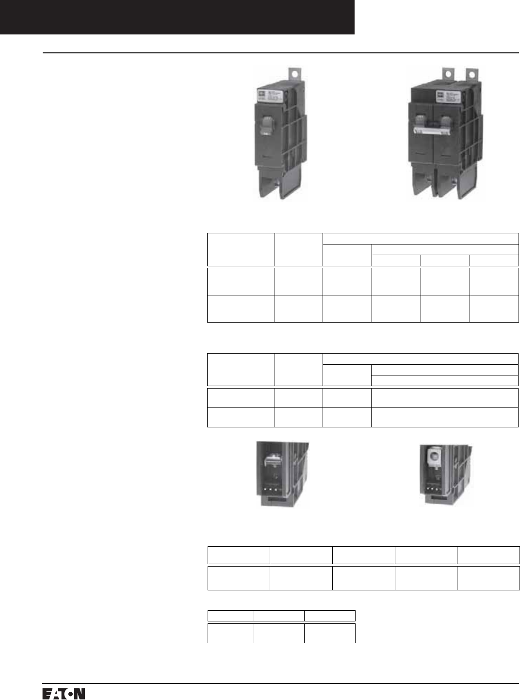
Miniature Circuit Breakers
QUICKLAG Industrial Circuit Breakers
Types GHBS and GBHS Solenoid-Operated, Remote-Controlled
Description
GHBS and GBHS circuit breakers are
bolt-on branch circuit breakers
designed for use in panelboards and
are ideally suited for lighting control
applications. In addition to provid-
ing conventional branch circuit
protection, they include a unique
solenoid-operated mechanism that
provides for efficient breaker pulse-
on and pulse-off operation when
used with a suitable controller like
the Cutler-Hammer Pow-R-Com-
mand lighting control system.
Product Features
■Bolt-on Line-Side Terminal
■Cable Connected Load-Side
Terminal
■3-Prong Control Terminal (Com-
mon, Solenoid, Auxiliary Switch)
■Bi-Metal Assembly for Thermal
Overload Protection
■Fast Acting Short Circuit
Protection
■Arc-Runner and Arc-Chute
Assembly for Fast Acting Arc
Extinction
■Three Position Handle: OFF, TRIP
(Center), ON
■Handle in “ON” Position Enables
Remote Control
■Handle in “OFF” Position Disables
Remote Control
■Handle Permits Manual Switch-
ing When Control Power is Lost
■Mechanical Trip Indicator Window
(Red-ON, Green-OFF/TRIPPED)
■15 and 20 Ampere Breakers SWD
(Switching Duty) Rated
■HID Ratings for HID (High Inten-
sity Discharge) Lighting
■Auxiliary Switch for Control
Circuit Feedback
➀All UL listed circuit breakers are HID (High
Intensity Discharge) rated.
➁Continuous current rating at 40°C.
Dimensions in parentheses in millimeters.
Dimensions Per Pole, Inches (mm)
Width Height Depth
1.000
(25.40)
4.125
(104.78)
2.810
(71.37)
1-Pole 2-Pole
Terminal Type
For load-side. Terminals are UL listed as suitable for wire type and size given below.
Circuit Breaker
Amperes
Terminal
Type
Screw Head
Type
Wire
Type
AWG Wire
Range
15-20 Clamp Slotted Cu/Al #14-#10
30 Box Slotted Cu/Al #14-#2
15-20 Amperes 30 Amperes
GBHS CSA 22.2 Interrupting Ratings
Circuit
Breaker
Type
Number of
Poles
Interrupting Capacity (Symmetrical Amperes)
Rating
Amperes➁
Volts Ac (50/60 Hz)
347/600
GBHS1015D
GBHS1020D
1
1
15
20
10,000
10,000
GBHS2015D
GBHS2020D
2
2
15
20
10,000
10,000
GHBS UL 489 Interrupting Ratings
Circuit
Breaker
Type➀
Number of Poles Interrupting Capacity (Symmetrical Amperes)
Rating
Amperes➁
Volts Ac (50/60 Hz)
120 240 277/480
GHBS1015D
GHBS1020D
GHBS1030D
1
1
1
15
20
30
65,000
65,000
65,000
–
–
–
14,000
14,000
14,000
GHBS2015D
GHBS2020D
GHBS2030D
2
2
2
15
20
30
–
–
–
65,000
65,000
65,000
14,000
14,000
14,000
Instruction Leaflet/FRED Number 15546

March 1999
PG.74A.01.T.E
Cutler-Hammer 15
Miniature Circuit Breakers
QUICKLAG Industrial Circuit Breakers
Types GHBS and GBHS Solenoid-Operated, Remote-Controlled
Typical Single-Pole Circuit Breaker Schematic Diagram and
Conductor Plug Wiring Connections
Circuit Breaker Schematic Diagram and Conductor Plug Wiring
Connections for 2-Pole
2-Pole Circuit Breaker
SolenoidCommon
28 Vac
Auxiliary
Solenoid
a
Solenoid a
1/2 Cycle
Maximum
28 Vac
Pulse Source
AMP Inc.
Conductor
Plug
Circuit
Breaker
Open/Closed
Status
Solenoid
Auxiliary
Switch
Common
Conductor
Plug (As Viewed
From End)
Circuit Breaker
Solenoid
Solenoid
a
Solenoid
Auxiliary
Switch
Common
28 Vac
Common
AMP Inc.
Conductor
Plug
1/2 Cycle
Maximum
28 Vac
Pulse Source
Circuit Breaker
Open/Closed
Status
Conductor
Plug (As
Viewed From
End)
Auxiliary
Remote Control Operation
The remote-control capability of
the breaker is “armed” when the
breaker handle is manually switched
to the “ON” position. Once armed,
the breaker can be pulsed “ON” and
“OFF” by a controller device which
provides an ac pulse of specified
magnitude and duration to the sole-
noid operated mechanism. Control
connections to the breaker are pro-
vided through a male conductor
plug (supplied by others) which
snaps into the female connector
provided with the breaker.
A normally open (a) auxiliary con-
tact provides for breaker “ON”/“OFF”
status indication to the remote
controller and/or indicating lamp.
The remote-control capability of the
breaker is “disarmed” when the
breaker handle is in the “OFF” or
“TRIPPED” position. In the event
the breaker automatically trips, the
breaker must be reset manually.
Breaker Solenoid and
Operating Data
■Ambient Temperature:
0-40° C
■Nominal Pulse Magnitude:
28 volts ac RMS
■Tolerance: +10% to -15% of
Nominal Voltage
■Pulse Duration: 1/2 cycle (8-10 ms)
■Minimum Recommended Pulse
Current at Nominal Voltage:
1-Pole: 4.9 Amperes Peak,
3.5 Amperes RMS
2-Pole: 7.84 Amperes Peak,
5.6 Amperes RMS
■Breaker Operating Time: 20-40 ms
■Maximum Breaker Cycling:
6 Operations per Minute
■Humidity: 0-95% non-Condensing
Wiring Diagrams

PG.74A.01.T.E
Cutler-Hammer
16 March 1999
Miniature Circuit Breakers
QUICKLAG Industrial Circuit Breakers
QUICKLAG International Rated Industrial Circuit Breakers Plug-on, Bolt-on and Cable-in/Cable-out
Description
QUICKLAG International
Circuit Breakers
Plug-on Type HQP: 10-100 Amperes
Bolt-on Type BA: 10-100 Amperes
Cable-in/Cable-out Type QC:
10-100 Amperes
Built and Test Certified to BS3871,
Pt. 1 50/60 Hz, 40°C
QUICKLAG International Ground
Fault Circuit Breakers
Plug-on Type GFXB: 10-40 Amperes
Bolt-on Type GFXBB: 10-40 Amperes
Cable-in/Cable-out Type GFXBC:
10-40 Amperes
Built and Test Certified to
BS3871, Pt. 1
BS3871, Section 31-C
BS4293
50/60 Hz, 40°C
30 mA Sensitivity
Interrupting Ratings
Suffix E Suffix HE
NEMA
120/240 Vac
10,000 AIC 10,000 AIC
BS3871
220/380,
240/415 Vac
3,000 AIC 6,000 AIC
Interrupting Rating
BS3871
220/380, 240/415 Vac
3,000 AIC
Shipping Data
Miniature
Circuit
Breaker
No.
of
Poles
Std.
Carton
Qty.
Approx.
Carton
Weight
Lbs.
(Kgs)
Approx.
Standard
Carton
Dimensions
Inches (mm)
QUICKLAG
Types B,
P, C – All
1 24 9.000
(4.09)
12.500 (317.50)
x 7.500 (190.50)
x 5.000 (127.00)
QUICKLAG
Types B,
P, C – All
2 12 9.000
(4.09)
12.500 (317.50)
x 7.500 (190.50)
x 5.000 (127.00)
QUICKLAG
Types B,
P, C – All
3 8 9.000
(4.09)
12.500 (317.50)
x 7.500 (190.50)
x 5.000 (127.00)
QUICKLAG Ground Fault
Type P –
All
1 20 11.000
(4.99)
12.500 (317.50)
x 6.500 (165.10)
x 5.000 (127.00)
Types B
and
C – All
1 20 11.000
(4.99)
12.500 (317.50)
x 7.000 (177.80)
x 5.500 (139.70)
Types P
and
B – All
2 5 5.000
(2.27)
12.500 (317.50)
6.000 (152.40)
4.500 (114.30)
Breaker Catalog Numbers
Continuous
Ampere
Rating at
40°C
Catalog Number
1-Pole 2-Pole 3-Pole Gound Fault
1-Pole 30 mA
Sensitivity
240/415 Vac 240/415 Vac 240/415 Vac 240/415 Vac
3,000 Amperes I.C. (M3) Plug-on Thermal-Magnetic Circuit Breakers
10
15
16
20
25
30
32
40
50
60
70
90
100
HQP1010E
HQP1015E
–
HQP1020E
HQP1025E
HQP1030E
–
HQP1040E
HQP1050E
HQP1060E
HQP1070E
–
–
HQP2010E
HQP2015E
–
HQP2020E
HQP2025E
HQP2030E
–
HQP2040E
HQP2050E
HQP2060E
HQP2070E
HQP2090E
HQP2100E
HQP3010E
HQP3015E
–
HQP3020E
HQP3025E
HQP3030E
–
HQP3040E
HQP3050E
HQP3060E
HQP3070E
HQP3090E
HQP3100E
GFXB110B2
GFXB115B2
GFXB116B2
GFXB120B2
GFXB125B2
GFXB130B2
GFXB132B2
GFXB140B2
–
–
–
–
–
6,000 Ampere I.C. (M6) Plug-on Thermal-Magnetic Circuit Breakers
15
20
25
30
40
50
60
70
90
100
HQP1015HE
HQP1020HE
HQP1025HE
HQP1030HE
HQP1040HE
HQP1050HE
HQP1060HE
HQP1070HE
–
–
HQP2015HE
HQP2020HE
HQP2025HE
HQP2030HE
HQP2040HE
HQP2050HE
HQP2060HE
HQP2070HE
HQP2090HE
HQP2100HE
HQP3015HE
HQP3020HE
HQP3025HE
HQP3030HE
HQP3040HE
HQP3050HE
HQP3060HE
HQP3070HE
HQP3090HE
HQP3100HE
–
–
–
–
–
–
–
–
–
–
3,000 Ampere I.C. (M3) Bolt-on Thermal-Magnetic Circuit Breakers
10
15
16
20
25
30
32
40
50
60
70
90
100
BAB1010E
BAB1015E
–
BAB1020E
BAB1025E
BAB1030E
–
BAB1040E
BAB1050E
BAB1060E
BAB1070E
–
–
BAB2010E
BAB2015E
–
BAB2020E
BAB2025E
BAB2030E
–
BAB2040E
BAB2050E
BAB2060E
BAB2070E
BAB2090E
BAB2100E
BAB3010E
BAB3015E
–
BAB3020E
BAB3025E
BAB3030E
–
BAB3040E
BAB3050E
BAB3060E
BAB3070E
BAB3090E
BAB3100E
GFXBB110B2
GFXBB115B2
GFXBB116B2
GFXBB120B2
GFXBB125B2
GFXBB130B2
GFXBB132B2
GFXBB140B2
–
–
–
–
–
6,000 Ampere I.C. (M6) Bolt-on Thermal-Magnetic Circuit Breakers
15
20
25
30
40
50
60
70
90
100
BAB1015HE
BAB1020HE
BAB1025HE
BAB1030HE
BAB1040HE
BAB1050HE
BAB1060HE
BAB1070HE
–
–
BAB2015HE
BAB2020HE
BAB2025HE
BAB2030HE
BAB2040HE
BAB2050HE
BAB2060HE
BAB2070HE
BAB2090HE
BAB2100HE
BAB3015HE
BAB3020HE
BAB3025HE
BAB3030HE
BAB3040HE
BAB3050HE
BAB3060HE
BAB3070HE
BAB3090HE
BAB3100HE
–
–
–
–
–
–
–
–
–
–
3,000 Ampere I.C. (M3) Cable-in/Cable-out Thermal-Magnetic Circuit Breakers
10
15
16
20
25
30
32
40
50
60
70
90
100
QC1010E
QC1015E
–
QC1020E
QC1025E
QC1030E
–
QC1040E
QC1050E
QC1060E
QC1070E
–
–
QC2010E
QC2015E
–
QC2020E
QC2025E
QC2030E
–
QC2040E
QC2050E
QC2060E
QC2070E
QC2090E
QC2100E
QC3010E
QC3015E
–
QC3020E
QC3025E
QC3030E
–
QC3040E
QC3050E
QC3060E
QC3070E
QC3090E
QC3100E
GFXBC110B2
GFXBC115B2
GFXBC116B2
GFXBC120B2
GFXBC125B2
GFXBC130B2
GFXBC132B2
GFXBC140B2
–
–
–
–
–
6,000 Ampere I.C. (M6) Cable-in/Cable-out Thermal-Magnetic Circuit Breakers
15
20
25
30
40
50
60
70
90
100
QC1015HE
QC1020HE
QC1025HE
QC1030HE
QC1040HE
QC1050HE
QC1060HE
QC1070HE
–
–
QC2015HE
QC2020HE
QC2025HE
QC2030HE
QC2040HE
QC2050HE
QC2060HE
QC2070HE
QC2090HE
QC2100HE
QC3015HE
QC3020HE
QC3025HE
QC3030HE
QC3040HE
QC3050HE
QC3060HE
QC3070HE
QC3090HE
QC3100HE
–
–
–
–
–
–
–
–
–
–
Time/Current Curves, Dimension Sheets, Application Data
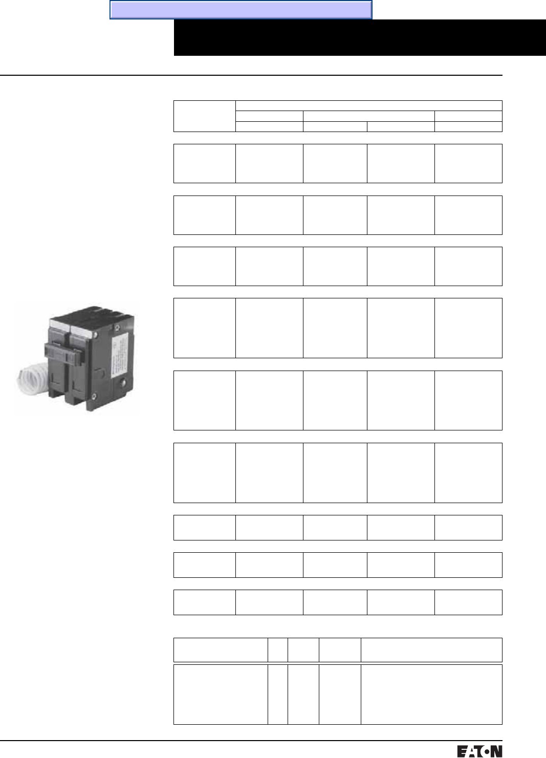
March 1999
PG.74A.01.T.E
Cutler-Hammer 17
Miniature Circuit Breakers
QUICKLAG Industrial Circuit Breakers
QUICKLAG Industrial Circuit Breakers Special Application Breakers
Description
QUICKLAG Switching Neutral
Circuit Breakers
Plug-on Type HQP: 10-30 Amperes,
1 and 2 Poles, 10,000 AIC
Bolt-on Type BA: 10-30 Amperes,
1 and 2 Poles, 10,000 AIC
Cable-in Type QC: 10-30 Amperes,
1 and 2 Poles, 10,000 AIC
Switching Neutral QUICKLAG Break-
ers available in one- and two-pole
configurations, plus neutral pole for
applications in accordance with NEC
514-5, 240-22, and 380-2. A one-pole
device takes two pole spaces, and a
two-pole device takes three pole
spaces.
QUICKLAG Type P
Switching Neutral
QUICKLAG HID (High Intensity
Discharge) Breakers
Plug-on Type HQP: 15-60 Amperes,
1 and 2 Poles, 10,000 AIC
Bolt-on Type BA: 15-60 Amperes,
1 and 2 Poles, 10,000 AIC
Cable-in Type QC: 15-60 Amperes,
1 and 2 Poles, 10,000 AIC
Breakers designed specifically for
use with high intensity discharge
(HID) lighting applications. (UL listed
as standard lighting breakers.)
Molded Case Switches
Non-Automatic QUICKLAG Molded
Case Switch
Plug-on Type HQP: 50, 60,100
Amperes, 1, 2 and 3 Poles
Bolt-on Type BA: 50, 60,100
Amperes, 1, 2 and 3 Poles
Cable-in Type QC: 50, 60,100
Amperes, 1, 2 and 3 Poles
Breaker Catalog Numbers
Continuous
Ampere
Rating 40°C
Catalog Number
1-Pole➀2-Pole➀3-Pole➀
120/240 Vac 120/240 Vac 240 Vac 240 Vac
QUICKLAG Type: HQP Switching Neutral Thermal-Magnetic Breakers
10
15
20
25
30
HQP2010B
HQP2015B
HQP2020B
HQP2025B
HQP2030B
HQP3010B
HQP3015B
HQP3020B
HQP3025B
HQP3030B
–
–
–
–
–
–
–
–
–
–
QUICKLAG Type: BA Switching Neutral Thermal-Magnetic Breakers
10
15
20
25
30
BAB2010C
BAB2015C
BAB2020C
BAB2025C
BAB2030C
BAB3010C
BAB3015C
BAB3020C
BAB3025C
BAB3030C
–
–
–
–
–
–
–
–
–
–
QUICKLAG Type: QC Switching Neutral Thermal-Magnetic Breakers
10
15
20
25
30
QC2010B
QC2015B
QC2020B
QC2025B
QC2030B
QC3010B
QC3015B
QC3020B
QC3025B
QC3030B
–
–
–
–
–
–
–
–
–
–
QUICKLAG Type: HQP HID (High Intensity Discharge) Thermal-Magnetic Breakers
15
20
25
30
35
40
50
60
HQP1015D
HQP1020D
HQP1025D
HQP1030D
HQP1035D
HQP1040D
HQP1050D
HQP1060D
HQP2015D
HQP2020D
HQP2025D
HQP2030D
HQP2035D
HQP2040D
HQP2050D
HQP2060D
–
–
–
–
–
–
–
–
–
–
–
–
–
–
–
–
QUICKLAG Type: BA HID (High Intensity Discharge) Thermal-Magnetic Breakers
15
20
25
30
35
40
50
60
BAB1015D
BAB1020D
BAB1025D
BAB1030D
BAB1035D
BAB1040D
BAB1050D
BAB1060D
BAB2015D
BAB2020D
BAB2025D
BAB2030D
BAB2035D
BAB2040D
BAB2050D
BAB2060D
–
–
–
–
–
–
–
–
–
–
–
–
–
–
–
–
QUICKLAG Type: QC HID (High Intensity Discharge) Thermal-Magnetic Breakers
15
20
25
30
35
40
50
60
QC1015D
QC1020D
QC1025D
QC1030D
QC1035D
QC1040D
QC1050D
QC1060D
QC2015D
QC2020D
QC2025D
QC2030D
QC2035D
QC2040D
QC2050D
QC2060D
–
–
–
–
–
–
–
–
–
–
–
–
–
–
–
–
QUICKLAG Type: HQP Non-Auto Molded Case Switches
50
60
100
HQP1050N
HQP1060N
HQP1100N
–
–
–
HQP2050N
HQP2060N
HQP2100N
HQP3050N
HQP3060N
HQP3100N
QUICKLAG Type: BA Non-Auto Molded Case Switches
50
60
100
BAB1050N
BAB1060N
BAB1100N
–
–
–
BAB2050N
BAB2060N
BAB2100N
BAB3050N
BAB3060N
BAB3100N
QUICKLAG Type: QC Non-Auto Molded Case Switches
50
60
100
QC1050N
QC1060N
QC1100N
–
–
–
QC2050N
QC2060N
QC2100N
QC3050N
QC3060N
QC3100N
Shipping Data
Miniature Circuit Breaker No.
of
Poles
Standard
Carton
Quantity
Approximate
Carton Weight
Lbs. (Kgs)
Approximate Standard Carton
Dimensions Inches (mm)
QUICKLAG Types B, P, C – All
QUICKLAG Types B, P, C – All
QUICKLAG Types B, P, C – All
QUICKLAG Ground Fault
Type P – All
Types B and C – All
Types P and B – All
1
2
3
1
1
2
24
12
8
20
20
5
9.000 (4.09)
9.000 (4.09)
9.000 (4.09)
11.000 (4.99)
11.000 (4.99)
5.000 (2.27)
12.500 (317.50) x 7.500 (190.50) x 5.000 (127.00)
12.500 (317.50) x 7.500 (190.50) x 5.000 (127.00)
12.500 (317.50) x 7.500 (190.50) x 5.000 (127.00)
12.500 (317.50) x 6.500 (165.10) x 5.000 (127.00)
12.500 (317.50) x 7.000 (177.80) x 5.500 (139.70)
12.500 (317.50) x 6.000 (152.40) x 4.500 (114.30)
➀All products UL and CSA listed.
Time/Current Curves, Dimension Sheets, Application Data
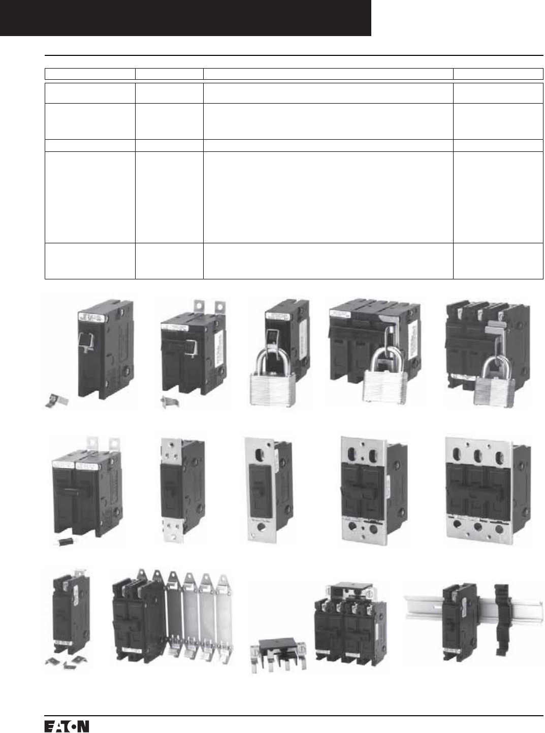
PG.74A.01.T.E
Cutler-Hammer
18 March 1999
Miniature Circuit Breakers
QUICKLAG Industrial Circuit Breakers
QUICKLAG Industrial Circuit Breakers Accessories
Accessory Type➀Catalog Number Description Order in Multiples of
Handle Locks:
Non-padlockable
QL1NPL
QL23NPL
QUICKLAG Type P, B, C – 1 Pole
QUICKLAG Type P, B, C – 2, 3 Poles
10
10
Handle Locks:
Padlockable
QL1PL
QLPB123PL
QC123PL
QLGF12PL
QUICKLAG Type P, B, C – 1 Pole
QUICKLAG Type P, B – 1, 2, 3 Poles
QUICKLAG Type C – 1, 2, 3 Poles
Ground Fault Padlock Device Type P, B – 1, 2 Poles
10
10
10
10
Handle Tie QL1HT QUICKLAG Handle Tie - 1 Pole 100
Mounting Hardware QCFCLIP
QC1FP
QC2FP
QC3FP
QC1FPLOFF
QC2FPLOFF
QC3FPLOFF
QCBCLIP
QC6BP
QC4CONB
QCDINADAPT
QUICKLAG Type C Face Mounting Clip
QUICKLAG Type C Face Mounting Plate – 1 Pole
QUICKLAG Type C Face Mounting Plate – 2 Poles
QUICKLAG Type C Face Mounting Plate – 3 Poles
QUICKLAG Type C Face Mounting Plate and Lock-off (Off Only) – 1 Pole
QUICKLAG Type C Face Mounting Plate and Lock-off (Off Only) – 2 Pole
QUICKLAG Type C Face Mounting Plate and Lock-off (Off Only) – 3 Pole
QUICKLAG Type C Base Mounting Clamp
QUICKLAG Base Mounting Plate – 6 Poles Total
QUICKLAG Type C Single Point Connector
QUICKLAG Type C DIN Rail Adapter
24
10
10
10
10
10
10
100
10
10
6
Dummy Breakers HQP1000
BAB1000
QC1000
QC30SAMPLE
QUICKLAG Type P
QUICKLAG Type B
QUICKLAG Type C
QUICKLAG Type C Clear Choice Breaker
1
1
1
4
QL23NPL QL1PL
QCBCLIP QC6BP QC4CONB QCDINADAPT
➀See pages 7 and 8 for QCR and QCF accessories.
QL1NPL QLPB123PL QC123PL
QL1HT QCFCLIP QC1FP QC2FP QC3FP

March 1999
PG.74A.01.T.E
Cutler-Hammer 19
Miniature Circuit Breakers
QUICKLAG Industrial Circuit Breakers
QUICKLAG Industrial Circuit Breakers Modifications/Terminals
Spare Terminal Hardware Screws (Lugs not Included)
Catalog Number Order in Multiples of Terminal Type Description
QLLDTSA
QLLDTSB
QLLDTSC
QLBHTSE
QLLNTSFG
10
10
10
10
10
A
B
C
E
F and G
QUICKLAG Terminal Screw
QUICKLAG Terminal Screw
QUICKLAG Terminal Screw
QUICKLAG Binding Head Terminal Screw and Clamp
QUICKLAG Terminal Screw
Factory Modifications➀
Type of Modification Breaker Types Catalog Suffix
Shunt Trip (Requires 1 extra pole space on right side)
120, 208, 240 Vac
12, 24, 48 Vac/dc
Draws 2.6A at 120V
Draws 11A at 24Vdc
QUICKLAG Types P, B and C
QUICKLAG Types P, B and C
S
S1
Special Calibration (50°C) QUICKLAG Types P, B and C V
Shock Testing QUICKLAG Types P, B and C L
Freeze Testing QUICKLAG Types P, B and C Y
Moisture-Fungus Treatment QUICKLAG Types P, B, C and Ground Fault F
Factory Installed Breaker Terminals
Breaker Type Continuous
Ampere
Rating
Standard Line Terminal Standard Load Terminal Optional Terminals
(20% List Price Adder)
Term
Type
Wire
Type
Wire
Range
Term
Type
Wire
Type
Wire
Range
Line Load
QUICKLAG Type P
HQP, QPHW,
QHPX, QHPW
10 to 30
35 to 50
55 to 125
Plug-on female clips which mate
with the bus stabs
A
B
C
Cu/Al
Cu/Al
Cu/Al
#14-#4
#14-#4
#8-1/0
N/A C
C
–
QUICKLAG Ground Fault
QPGF, QPHGF,
QPGFEP, QPHGFEP
10 to 30
40
Plug-on female clips which mate
with the bus stabs
A – 1-pole
D – 2-pole
D
Cu/Al
Cu/Al
Cu
#14-#4
#14-#8
#14-#8
N/A C
C
–
QUICKLAG Type B
BAB, QBHW,
HBAX, HBAW
10 to 30
35 to 50
55 to 125
Extended tangs which bolt
directly to the bus
A – 1- and 2- pole
B – 3-pole
C
Cu/Al
Cu/Al
Cu/Al
#14-#4
#14-#4
#8-1/0
N/A C
C
–
QUICKLAG Ground Fault
QBGF, QBHGF,
QBGFEP, QBHGFEP
10 to 30
40
Extended tangs which bolt
directly to the bus
A – 1-pole
D – 2-pole
D
Cu/Al
Cu/Al
Cu
#14-#4
#14-#8
#14-#8
N/A N/A
QUICKLAG Type C
QC, QCHW,
QHCX, QHCW
10 to 20
25 to 60
70 to 100
E
F
G
Cu/Al
Cu/Al
Cu/Al
#14-#10 E
B
C
Cu/Al
Cu/Al
Cu/Al
#14-#10
#14-#4
#8-1/0
F, G
E, G
E
F, G, H
E, F, G, H
E, G, H
QUICKLAG
QCR, QCF
10-55
60
A
A
Cu/Al
Cu
-#14
-#4
A
A
Cu/Al
Cu
#14
-#4
N/A N/A
QUICKLAG Ground Fault
QCGF, QCHGF,
QCGFEP, QCHGFEP
10 to 20
25 to 50
E
F
Cu/Al
Cu/Al
#14-#10 A
A
Cu/Al
Cu/Al
#14-#4
#14-#4
F, G
E, G
N/A
➀Contact Cutler-Hammer for factory modifications available for QCR and QCF breakers.
ABCD
E F G H
Catalog Suffix “P”
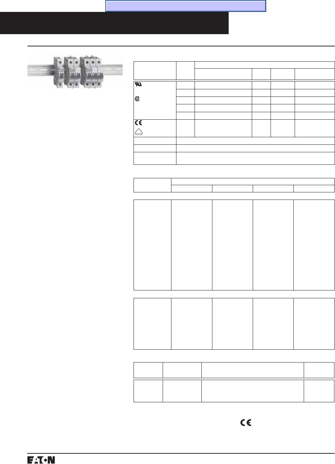
PG.74A.01.T.E
Cutler-Hammer
20 March 1999
Miniature Circuit Breakers
SPCL Supplementary Protectors
Supplementary Protectors Current Limiting Type Cable-in/Cable-out DIN Rail
➀130 Vdc rating based on 2 poles connected in
series.
Normally stocked.
Special order, contact Cutler-Hammer.
Minimum quantities apply.
SPCL Specifications
Standards
and Approvals
Number
of Poles
Electrical Ratings
Continuous Current
(Amperes)
Vac
50/60 Hz
Vdc Ampere Interrupting
Capacity
UL 1077
File No. E162396
CSA 22.2
File No. LR105580-1
1 0.5-63 120 12-65 10 kA
2 0.5-63 240 12-130➀10 kA
3-4 0.5-63 240 10 kA
1 0.5-63 277 6 kA
2-4 0.5-63 480 5 kA
EN60898
VDE0660
1-4 0.5-63 240/415 10 kA
Overcurrent Curves Overcurrent Curve Type B (3-5X) and Type C (5-10X) per VDE 0641, Part 11.
Degree of Protection IP20.
Connecting
Terminals
Suitable for Single-Core, Standard, and Flexible Conductors from #14 to #6 AWG (Cu).
Recommended Torque is 27 Inch-Pounds.
SPCL Supplementary Protector Catalog Numbers
Continuous
Ampere Rating
Catalog Number
1-Pole 2-Pole 3-Pole 4-Pole
C Curve
0.5
1
2
3
4
5
6
7
8
10
13
16
20
25
32
40
50
63
SPCL1C00
SPCL1C01
SPCL1C02
SPCL1C03
SPCL1C04
SPCL1C05
SPCL1C06
SPCL1C07
SPCL1C08
SPCL1C10
SPCL1C13
SPCL1C16
SPCL1C20
SPCL1C25
SPCL1C32
SPCL1C40
SPCL1C50
SPCL1C63
SPCL2C00
SPCL2C01
SPCL2C02
SPCL2C03
SPCL2C04
SPCL2C05
SPCL2C06
SPCL2C07
SPCL2C08
SPCL2C10
–
SPCL2C16
SPCL2C20
SPCL2C25
SPCL2C32
SPCL2C40
SPCL2C50
SPCL2C63
SPCL3C00
SPCL3C01
SPCL3C02
–
SPCL3C04
–
SPCL3C06
–
–
SPCL3C10
–
SPCL3C16
SPCL3C20
SPCL3C25
SPCL3C32
SPCL3C40
SPCL3C50
SPCL3C63
SPCL4C00
SPCL4C01
SPCL4C02
–
SPCL4C04
–
SPCL4C06
–
–
SPCL4C10
–
SPCL4C16
SPCL4C20
SPCL4C25
SPCL4C32
SPCL4C40
SPCL4C50
SPCL4C63
B Curve
6
10
13
16
20
25
32
40
50
63
SPCL1B06
SPCL1B10
SPCL1B13
SPCL1B16
SPCL1B20
SPCL1B25
SPCL1B32
SPCL1B40
SPCL1B50
SPCL1B63
SPCL2B06
SPCL2B10
–
SPCL2B16
SPCL2B20
SPCL2B25
SPCL2B32
SPCL2B40
SPCL2B50
SPCL2B63
SPCL3B06
SPCL3B10
–
SPCL3B16
SPCL3B20
SPCL3B25
SPCL3B32
SPCL3B40
SPCL3B50
SPCL3B63
SPCL4B06
SPCL4B10
–
SPCL4B16
SPCL4B20
SPCL4B25
SPCL4B32
SPCL4B40
SPCL4B50
SPCL4B63
Shipping Data
Packed in
Cartons of:
Carton Dimensions
Inches (mm)
Approximate
Weight Lbs.
(Kgs)
1-Pole Units
2-Pole Units
3-Pole Units
4-Pole Units
12
6
4
3
9.000 (228.60) x 4.000 (101.60) x 4.000 (101.60)
9.000 (228.60) x 4.000 (101.60) x 4.000 (101.60)
9.000 (228.60) x 4.000 (101.60) x 4.000 (101.60)
9.000 (228.60) x 4.000 (101.60) x 4.000 (101.60)
10.000 (4.54)
10.000 (4.54)
10.000 (4.54)
10.000 (4.54)
V
DE
SPCL protectors carry the CE mark in
accordance with Low Voltage Directive
(LVD) (73/23/EEC)
CE Mark
Description
UL 1077 Supplementary Protectors
Type SPCL Supplementary Protec-
tors are IEC circuit breakers that are
recognized by UL under UL 1077.
They are intended for use as over-
current protection within an appli-
ance or electrical equipment where
branch circuit protection (for exam-
ple a UL listed Molded Case Circuit
Breaker) has already been provided
or is not required.
Equipment and Control
Circuit Protection
These protectors are ideal for replac-
ing fuses in control circuits. Applica-
tions include protecting motor
control circuits, small control circuit
transformers, relays, contactor coils,
power supplies, PLC I/O points, appli-
ances, and electronic equipment.
Product Features
The Type SPCL Supplementary
Protectors are provided in light gray
cases with charcoal gray handles.
DIN-Rail Mounting: A quick snap-on
clip design allows easy installation
on 35mm DIN Rail.
Current-Limiting Design: Fast short
circuit interruption reduces let-
through energy, reducing damage
to the circuit.
Thermal-Magnetic Overcurrent
Protection: Types B and C overcur-
rent curves provide maximum
reliability and accuracy. Type B
protection is normally used for low
inrush applications. Type C protec-
tion is used for general purpose
industrial applications that require
higher inrush tolerance.
Center Trip Position: The breaker
handle has a unique center trip
“Reset” position that indicates an
overcurrent trip. “Off” (O) and “On”
(I) handle positions are visually indi-
cated by red and green flags.
Time/Current Curves, Dimension Sheets, Application Data
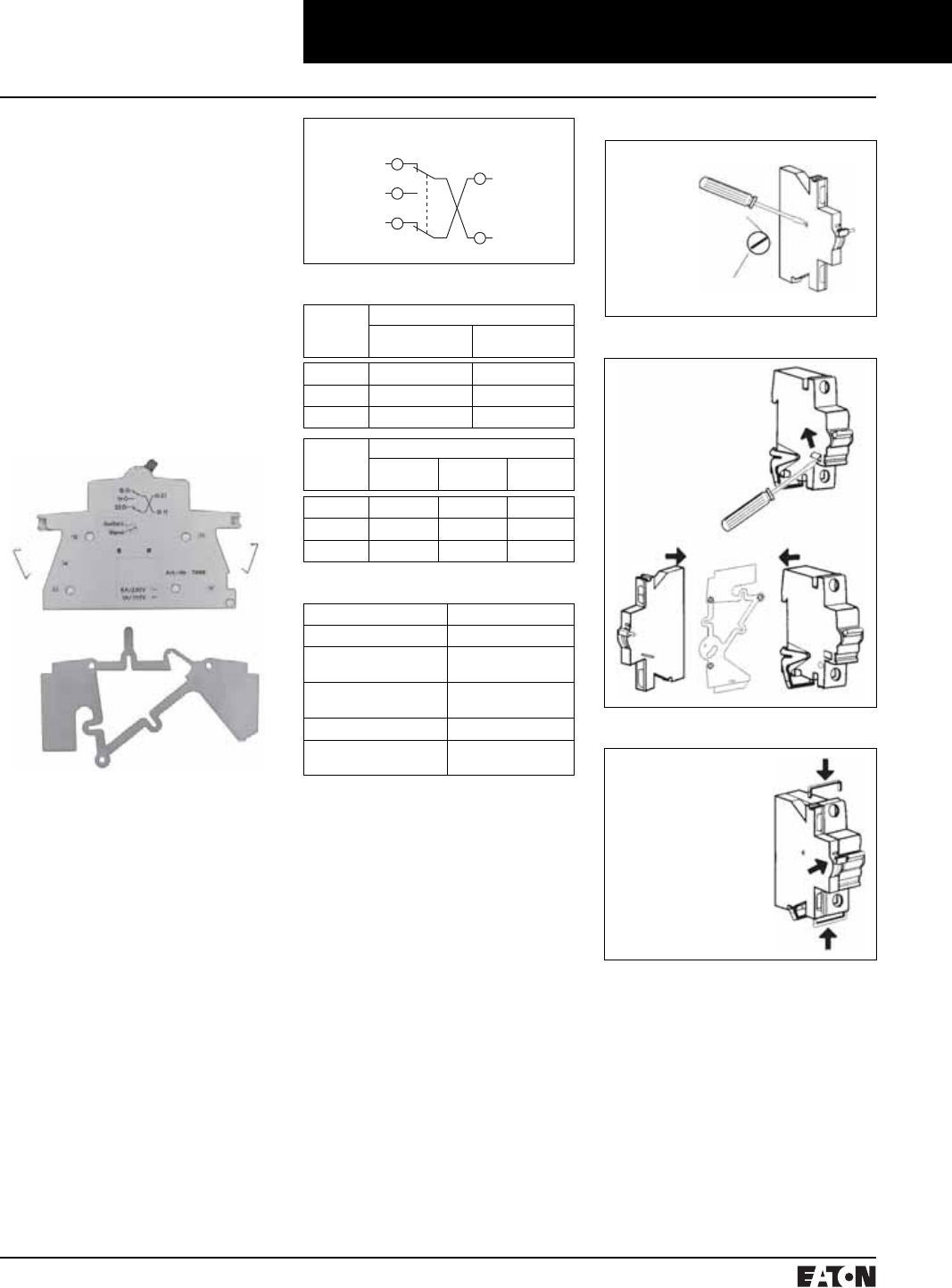
March 1999
PG.74A.01.T.E
Cutler-Hammer 21
Miniature Circuit Breakers
SPCL Supplementary Protectors
Supplementary Protectors Current Limiting Type Cable-in/Cable-out DIN Rail
SPCL Accessories
Auxiliary/Signal Switch Kit
Catalog Number SPCLUAUX is a
field mountable switch kit that
attaches to the left side of a SPCL
Protector. It is field selectable to
auxiliary or signal (bell alarm) con-
figuration. The switch is UL and CSA
approved for general purpose
ratings of 6 ampere at 240 Vac or
1 ampere at 125 Vdc. Contacts are
provided as indicated on the wiring
diagram. Screw-type terminals are
provided to accommodate up to #16
AWG wire. Recommended torque is
approximately 13 inch-pounds.
12
14
22
21
11
Wiring Diagram
Contact Charts
Contacts Auxiliary Switch Mode
Protector
Open
Protector Closed
11 to 12 X 0
11 to 14 0 X
21 to 22 X 0
Contacts Signal Switch Mode
Protector
Open
Protector
Closed
Protector
Tripped
11 to 12 0 0 X
11 to 14 X X 0
21 to 22 0 0 X
Technical Data
Rated Voltage: 230 Vac/110 Vdc
Rated Current: 6A Ac/1A Dc
Conductor Cross
Section:
To 1.5 mm2
(No 16 AWG)
Tightening Torque: 1 Nm
(13 inch-pounds)
Product: Catalog Number
Universal Auxiliary
Switch:
SPCLUAUX
Figure 1
Figure 2
Signaling
Switch
Auxiliary
Switch
Figure 3

PG.74A.01.T.E
Cutler-Hammer
22 March 1999
Miniature Circuit Breakers
SPCL Supplementary Protectors
Supplementary Protectors Current Limiting Type Cable-in/Cable-out DIN Rail
Lock-off Devices
Catalog Number Description
SPCLPLDEV Padlockable device, mounts on protector and includes provisions to accept
catalog number SPCLOCKEY Padlock
SPCLOCKEY Padlock with 3 keys
➀Per VDE 0606.
SPCL Accessories
Lock-off Devices
Bus Bar Systems
Finger Proofing Shield
Finger Proofing Shield
Catalog Number Description
SPCL2000 Clip-on finger proofing shield to enhance finger protection on SPCL protectors.
Plastic finger proofing shield clips into upper or lower terminal poles as required.
Bus Bar Systems
Catalog Number Description
SPCLIPB10MM Single-phase 240 Vac VDE approved Bus Bar, 1 meter in length, 10mm2 density
SPCL1PB16MM Single-phase 240 Vac VDE approved Bus Bar, 1 meter in length, 16mm2 density
Maximum Bus Bar Current➀
Conductor Density End Connect Center Connect
10 sq. mm 50 Amperes 100 Amperes
16 sq. mm 65 Amperes 130 Amperes

March 1999
PG.74A.01.T.E
Cutler-Hammer 23
Miniature Circuit Breakers
SPHM Supplementary Protectors
Supplementary Protectors Hydraulic Magnetic Type Cable-in/Cable-out DIN Rail
Description
UL 1077 Supplementary Protectors
Type SPHM Supplementary Protec-
tors are IEC circuit breakers that are
recognized by UL under UL 1077.
They are intended for use as over-
current protection within an appli-
ance or electrical equipment where
branch circuit protection (for exam-
ple a UL listed Molded Case Circuit
Breaker) has already been provided
or is not required.
Equipment and Control Circuit
Applications
These protectors are ideal for protect-
ing motor control circuits, CPTs,
relays, contactor coils, power supplies,
PLC I/O points, lighting circuits, appli-
ances, electronic equipment, and
replacing fuses.
Product Features
The Type SPHM Supplementary Pro-
tectors are provided in light gray cases
with charcoal gray handles. Handles
are marked with “O” for “Off” and “I”
for “On”.
DIN Rail Mounting: Easy installation
on 35mm DIN Rail. A spring loaded
clip is provided for quick release
from the DIN Rail mounting.
Heat-Induced Nuisance Tripping
Eliminated: The protector is designed
to “hold in” at 100% of continuous
rated current regardless of ambient
temperatures from -40 to +85°C.
Immediate Reset After Trip: The pro-
tector can be reset (closed) immedi-
ately after an overcurrent trip
without a “cooling off” period.
Precise Overcurrent Calibration: The
protector can be precisely calibrated
to a wide variety of current ranges
from 0.1 to 50 amperes continuous.
For special ratings not shown, con-
tact Cutler-Hammer.
Flexible Time-Characteristic Curves:
Long, Medium, and Short Delay
Curves are available. Long Delay are
for special extended inrush, Medium
Catalog Numbering System
Supplementary
Protector
Hydraulic
Magnetic
Code Delay Voltage Code Delay Curve
H 8X 50/60 Hz M
S
Medium
Short
2
3
R 18X 50/60 Hz L
M
S
Long
Medium
Short
10
20
30
Y➃25X 50/60 Hz L
M
S
Long
Medium
Short
251
252
253
J8XDc M
S
Medium
Short
2
3
S 18X Dc L
M
S
Long
Medium
Short
10
20
30
Z➃25X Dc L
M
S
Long
Medium
Short
251
252
253
S Switch Dc, 50/60 Hz W Switch –
Code Current➂
00R1 0.10 Ampere
0R25 0.25 Ampere
0R50 0.50 Ampere
0R75 0.75 Ampere
0001 1 Ampere
02R5 2.5 Ampere
0005 5 Ampere
07R5 7.5 Ampere
0010 10 Ampere
0015 15 Ampere
0020 20 Ampere
0025 25 Ampere
0030 30 Ampere
0035➂35 Ampere
0040➂40 Ampere
0050➂50 Ampere
Code Current
A➀Normally
Open➁
B➀Normally
Closed➁
Poles
Delay
Current
Rating
Auxiliary
Switch
S P H M 3 H M0 0 3 0
Inrush
Code Poles
1 1-Pole
2 2-Pole
3 3-Pole
4 4-Pole
Type
for general purpose, and Short Delay
for sensitive electronic applications.
1/2 Cycle High-Inrush Tolerance: The
protector can be provided with toler-
ance to various levels of 1/2 cycle
current spikes. General purpose
tolerance is 8X the continuous
current rating. Tolerance to 18X
and 25X are also available.
Environmental, Vibration, and
Shock Resistance: Mil-Spec qualifi-
cation for fungus resistance, humid-
ity, salt-spray resistance, and shock
vibration resistance.
Integral Auxiliary Switch (Optional):
One auxiliary switch contact (a or b)
can be factory installed per protector
pole. A separate pole for the contact
is not required.
➀One A or B contact maximum per pole.
Contacts will be arranged left to right (e.g.,)
BAB suffix on 3-pole breaker.
➁Contact position when breaker in open condi-
tion. Contacts rated 10 amperes at 250 Vac.
➂UL recognized to 250 Vac, 5 kA above 30
amperes.
➃Maximum of 40 amperes available at 25X
inrush.
General Specifications and Electrical Ratings
Standards and
Approvals
Continuous
Current Rating
Vac 50/60 Hz Vdc Interruption Cap Capacity
RMS Symmetrical
UL 1077 0.1 to 30 Amperes 277/480 3 kA
0.1 to 50 Amperes 250 5 kA
CSA 22.2 0.1 to 50 Amperes 80 5 kA
VDE 0660 0.1 to 50 Amperes 230/400 1.5 kA
IEC-380 0.1 to 50 Amperes 80 2 kA
Standards: UL Recognized under
UL 1077, CSA Certified to CSA 22.2.
Meets the requirements of IEC-380,
IEC-435, IEC-601, VDE 0660, VDE
601, VDE 0730, VDE 0750, VDE 0804,
VDE 0806
Inrush Tolerance: 8X (Standard),
18X, or 25X
Overcurrent Curves: Long Delay,
Medium Delay, or Short Delay
Operating Temperature: -40 to +85°C
Wire Range: Breaker Terminals:
14-6 AWG Copper, 35-inch-lbs
torque Auxiliary Switch Terminals:
16 AWG Copper, 3.5-inch-lbs torque
Auxiliary Switch: 10 Amperes at
250 Vac
Degree of Protection: IP-20

PG.74A.01.T.E
Cutler-Hammer
24 March 1999
Miniature Circuit Breakers
SPHM Supplementary Protectors
Supplementary Protectors Hydraulic Magnetic Type Cable-in/Cable-out DIN Rail
SPHM Catalog Numbers
Continuous
Current
Rating
(Amperes)
Catalog Number
8X (Standard Inrush Tolerance) Medium Delay Curve 2
1-Pole 277 Vac 2-Pole 277/480 Vac 3-Pole 277/480 Vac 4-Pole 277/480 Vac
0.1
0.25
0.50
0.75
1
2.5
5.0
7.5
10
15
20
25
30
SPHM1HM00R1
SPHM1HM0R25
SPHM1HM0R50
SPHM1HM0R75
SPHM1HM0001
SPHM1HM02R5
SPHM1HM0005
SPHM1HM07R5
SPHM1HM0010
SPHM1HM0015
SPHM1HM0020
SPHM1HM0025
SPHM1HM0030
SPHM2HM00R1
SPHM2HM0R25
SPHM2HM0R50
SPHM2HM0R75
SPHM2HM0001
SPHM2HM02R5
SPHM2HM0005
SPHM2HM07R5
SPHM2HM0010
SPHM2HM0015
SPHM2HM0020
SPHM2HM0025
SPHM2HM0030
SPHM3HM00R1
SPHM3HM0R25
SPHM3HM0R50
SPHM3HM0R75
SPHM3HM0001
SPHM3HM02R5
SPHM3HM0005
SPHM3HM07R5
SPHM3HM0010
SPHM3HM0015
SPHM3HM0020
SPHM3HM0025
SPHM3HM0030
SPHM4HM00R1
SPHM4HM0R25
SPHM4HM0R50
SPHM4HM0R75
SPHM4HM0001
SPHM4HM02R5
SPHM4HM0005
SPHM4HM07R5
SPHM4HM0010
SPHM4HM0015
SPHM4HM0020
SPHM4HM0025
SPHM4HM0030
Continuous
Current Rating
(Amperes)
8X (Standard Inrush Tolerance) Medium Delay Curve 2
1-Pole 250 Vac 2-Pole 250 Vac 3-Pole 250 Vac 4-Pole 250 Vac
35
40
50
SPHM1HM0035
SPHM1HM0040
SPHM1HM0050
SPHM2HM0035
SPHM2HM0040
SPHM2HM0050
SPHM3HM0035
SPHM3HM0040
SPHM3HM0050
SPHM4HM0035
SPHM4HM0040
SPHM4HM0050
Continuous
Current Rating
(Amperes)
18X (High Inrush Tolerance) Medium Delay Curve 20
1-Pole 277 Vac 2-Pole 277/480 Vac 3-Pole 277/480 Vac 4-Pole 277/480 Vac
0.1
0.25
0.50
0.75
1
2.5
5
7.5
10
15
20
25
30
SPHM1RM00R1
SPHM1RM0R25
SPHM1RM0R50
SPHM1RM0R75
SPHM1RM0001
SPHM1RM02R5
SPHM1RM0005
SPHM1RM07R5
SPHM1RM0010
SPHM1RM0015
SPHM1RM0020
SPHM1RM0025
SPHM1RM0030
SPHM2RM00R1
SPHM2RM0R25
SPHM2RM0R50
SPHM2RM0R75
SPHM2RM0001
SPHM2RM02R5
SPHM2RM0005
SPHM2RM07R5
SPHM2RM0010
SPHM2RM0015
SPHM2RM0020
SPHM2RM0025
SPHM2RM0030
SPHM3RM00R1
SPHM3RM0R25
SPHM3RM0R50
SPHM3RM0R75
SPHM3RM0001
SPHM3RM02R5
SPHM3RM0005
SPHM3RM07R5
SPHM3RM0010
SPHM3RM0015
SPHM3RM0020
SPHM3RM0025
SPHM3RM0030
SPHM4RM00R1
SPHM4RM0R25
SPHM4RM0R50
SPHM4RM0R75
SPHM4RM0001
SPHM4RM02R5
SPHM4RM0005
SPHM4RM07R5
SPHM4RM0010
SPHM4RM0015
SPHM4RM0020
SPHM4RM0025
SPHM4RM0030
Continuous
Current Rating
(Amperes)
18X (High Inrush Tolerance) Medium Delay Curve 20
1-Pole 250 Vac 2-Pole 250 Vac 3-Pole 250 Vac 4-Pole 250 Vac
35
40
50
SPHM1RM0035
SPHM1RM0040
SPHM1RM0050
SPHM2RM0035
SPHM2RM0040
SPHM2RM0050
SPHM3RM0035
SPHM3RM0040
SPHM3RM0050
SPHM4RM0035
SPHM4RM0040
SPHM4RM0050
1-Pole 4-Pole3-Pole2-Pole
Normally stocked.
Special order, contact Cutler-Hammer.
Minimum quantities apply. Contact
Cutler-Hammer for price and availability
for 400 Hz, Dc, Auxiliary Switch, and other
catalog number combinations not shown.
Shipping Data
Shipped in
Cartons of:
Carton Dimensions Inches (mm) Approx. Weight
Lbs. (Kgs)
1-Pole Units
2-Pole Units
3-Pole Units
4-Pole Units
12
6
4
3
10.500 (266.70) x 4.125 (104.78) x 4.500 (114.30)
10.500 (266.70) x 4.125 (104.78) x 4.500 (114.30)
10.500 (266.70) x 4.125 (104.78) x 4.500 (114.30)
10.500 (266.70) x 4.125 (104.78) x 4.500 (114.30)
15.000 (6.81)
15.000 (6.81)
15.000 (6.81)
15.000 (6.81)
Time/Current Curves, Dimension Sheets, Application Data

March 1999
PG.74A.01.T.E
Cutler-Hammer 25
Molded Case Circuit Breakers
15-100 Amperes
Series C G-Frame
Interrupting Capacity Ratings
UL489 Interrupting Capacity Ratings
Circuit
Breaker
Type
Number
of Poles
Interrupting Capacity (Symmetrical Amperes) (kA) Page
Number
Volts Ac (50/60 Hz) Volts Dc
120 240 277 480 125 250➀➁
GD 3 – 65 – 22 – 10 26
Circuit
Breaker
Type
Number
of Poles
Interrupting Capacity (Symmetrical Amperes) (kA) Page
Number
Volts Ac (50/60 Hz) Volts Dc
120 240 277 480Y/277 125 125/250
GB 1
2, 3
65
–
–
65
–
–
–
–
14➂
–
–
14
27
27
GHB 1
2, 3
65
–
–
65
14
–
–
14
14➂
–
–
14
27
27
GC 1
2, 3
65
–
–
65
–
–
–
–
14➂
–
–
14
28
28
GHC 1
2, 3
65
–
–
65
14
–
–
14
14➂
–
–
14
28
28
➀Two poles of 3-pole circuit breaker.
➁Time constant is 8 milliseconds minimum.
➂15 through 70A breakers only.
➃Not UL listed sizes.
■All two- and three-pole circuit
breakers are of the common trip
type. On all 3-phase Delta (240V)
Grounded B phase applications,
refer to Cutler-Hammer.
■Single-pole circuit breakers, 15
and 20 amperes. Switching duty
rated (SWD) for fluorescent light-
ing applications.
■All G-frame circuit breakers are
suitable for reverse feed use.
■HACR rated.
Catalog Numbering System
This information is presented only as an aid to under-
standing catalog numbers. It is not to be used to build
catalog numbers for circuit breakers or trip units.
Circuit Breaker/Frame Catalog Number
GD 3 100
Circuit
Breaker
Type
GD
GB
GHB
GC
GHC
Number
of Poles
1: 1 Pole
2: 2 Pole
3: 3 Pole
Trip
Amperes
15
20
24
30
35
40
45
50
60
70
80
90
100
Suffix
K: Molded Case Switch
D: Ring Type Terminals
C: Steel Collars
V: 50°C
J01: Fungus Proofed
R01: Shock Tested
F01: Freeze Tested
Terminal Types
For line and load-side. Terminals are UL listed as suitable
for wire type and size given below.
Circuit
Breaker
Amperes
Terminal
Type
Material
Screw
Head
Type
Wire
Type
AWG
Wire
Range
Metric Wire➃
Range (mm2)
Standard
15-20
25-100
Clamp (Plated Steel)
Pressure (Aluminum Body)
Slotted
Slotted
Cu/Al
Cu/Al
#14-10
#10-1/0
2.5-4
4-50
Optional
15-50 Pressure (Steel Body) Slotted Cu – –

PG.74A.01.T.E
Cutler-Hammer
26 March 1999
Molded Case Circuit Breakers
15-100 Amperes
Series C G-Frame
Typical Series C G-Frame Circuit Breaker
Instruction Leaflet/FRED Number 29C102
Type GD Thermal-Magnetic Circuit Breakers with Non-Interchangeable
Trip-Units
Maximum
Continuous
Ampere Rating
@ 40°C
480 Vac Maximum, 250 Vdc➀Catalog Number
(Includes binding
head screws)
22 kAIC @ 480 Vac
Catalog Number (Includes Line and
Load Terminals)
3-Pole
15
20
25
30
35
40
45
50
60
70
80
90
100
GD3015
GD3020
GD3025
GD3030
GD3035
GD3040
GD3045
GD3050
GD3060
GD3070
GD3080
GD3090
GD3100
GD3015D
GD3020D
GD3025D
GD3030D
GD3035D
GD3040D
GD3045D
GD3050D
GD3060D
GD3070D
GD3080D
GD3090D
GD3100D
Molded Case Switches
Instruction Leaflet/FRED Number 29C102
Maximum
Continuous
Ampere Rating
@ 40°C
480 Vac Maximum, 250 Vdc
Catalog Number (Includes Line and Load Terminals)
3-Pole
60
100
GD3060K
GD3100K
Time/Current Curves, Dimension Sheets, Application Data

March 1999
PG.74A.01.T.E
Cutler-Hammer 27
Molded Case Circuit Breakers
15-100 Amperes
Series C G-Frame
Type GHBGFEP Bolt-on Panelboard 30mA Industrial Ground Fault Circuit Protectors
15-60 Amperes, 277 Volt, 50/60 Hz
These circuit breakers meet the
requirements of UL489 and UL1053.
Operational voltage 240V to 305V.
Interrupting Capacity Ratings
Circuit
Breaker
Type
Number
of Poles
Interrupting Capacity
(Symmetrical Amperes)
277 Volts Ac (50/60 Hz)
GHBGFEP 2 14,000
Single Phase
(Requires 2 Poles)
Instruction Leaflet/FRED Number 29C193
Type GHBGFEP Bolt-on Panelboard 30mA
Industrial Ground Fault Circuit Protectors
with Non-Interchangeable Trip Units
Continuous
Ampere
Rating
@ 40°C
One Phase (Requires 2 Poles)
277V, 30mA
Catalog Number
15
20
30
40
50
60
GHBGFEP1015
GHBGFEP1020
GHBGFEP1030
GHBGFEP1040
GHBGFEP1050
GHBGFEP1060
Instruction Leaflet/FRED Number 15547
Type GHB Thermal-Magnetic Circuit Breakers with Non-Interchangeable Trip Units➃
Continuous
Ampere Rating
@ 40°C
277/480 Vac Maximum,
125 Vdc Maximum➀
277/480 Vac Maximum,
125/250 Vdc Maximum
277/480 Vac Maximum,
125/250 Vdc Maximum➁
1-Pole 2-Pole 3-Pole
Catalog Number
15
20
25
30
35
40
45
50
60
70
80
90
100
GHB1015➂
GHB1020➂
GHB1025
GHB1030
GHB1035
GHB1040
GHB1045
GHB1050
GHB1060
GHB1070
GHB1080
GHB1090
GHB1100
GHB2015➂
GHB2020➂
GHB2025
GHB2030
GHB2035
GHB2040
GHB2045
GHB2050
GHB2060
GHB2070
GHB2080
GHB2090
GHB2100
GHB3015➂
GHB3020➂
GHB3025
GHB3030
GHB3035
GHB3040
GHB3045
GHB3050
GHB3060
GHB3070
GHB3080
GHB3090
GHB3100
➀15 through 70 ampere circuit breakers only.
➁Use (2) outside poles.
➂Uses .190-32 screw type clamp terminals.
➃480Y/277V, circuit breakers (Type GHB)
not suitable for 3-phase Delta (480V).
These breakers meet the require-
ments of Federal Specification
W-C-375b as follows:
Types GB, GHB, 120 and 240 Volts:
1 Pole: Class 11a.
2, 3 Poles: Classes 10b, 11b, 12b,
14b, 15b
Type GHB, 277 and 480Y/277 Volts:
1 Pole: Classes 12c, 13a
2, 3 Poles: Class 13b
Type GB Thermal-Magnetic Circuit Breakers with Non-Interchangeable Trip Units
Continuous
Ampere Rating
@ 40°C
120 Vac Maximum,
125 Vdc Maximum➀
240 Vac Maximum,
125/250 Vdc Maximum
240 Vac Maximum,
125/250 Vdc Maximum➁
1-Pole 2-Pole 3-Pole
Catalog Number
15
20
25
30
35
40
45
50
60
70
80
90
100
GB1015➂
GB1020➂
GB1025
GB1030
GB1035
GB1040
GB1045
GB1050
GB1060
GB1070
GB1080
GB1090
GB1100
GB2015➂
GB2020➂
GB2025
GB2030
GB2035
GB2040
GB2045
GB2050
GB2060
GB2070
GB2080
GB2090
GB2100
GB3015➂
GB3020➂
GB3025
GB3030
GB3035
GB3040
GB3045
GB3050
GB3060
GB3070
GB3080
GB3090
GB3100
Types GB and GHB Bolt-On Panelboard Circuit Breakers
Typical GB
Time/Current Curves, Dimension Sheets, Application Data

PG.74A.01.T.E
Cutler-Hammer
28 March 1999
Molded Case Circuit Breakers
15-100 Amperes
Series C G-Frame
Instruction Leaflet/FRED Number 15548
Type GHC Thermal-Magnetic Circuit Breakers with Non-Interchangeable Trip Units
Continuous
Ampere Rating
@ 40°C
277 Vac Maximum,
125 Vdc Maximum➀
480Y/277 Vac Maximum,
125/250 Vdc Maximum
480Y/277 Vac Maximum,
125/250 Vdc Maximum➁
1-Pole 2-Pole 3-Pole
Catalog Number
15
20
25
30
35
40
45
50
60
70
80
90
100
GHC1015➂
GHC1020➂
GHC1025
GHC1030
GHC1035
GHC1040
GHC1045
GHC1050
GHC1060
GHC1070
GHC1080
GHC1090
GHC1100
GHC2015➂
GHC2020➂
GHC2025
GHC2030
GHC2035
GHC2040
GHC2045
GHC2050
GHC2060
GHC2070
GHC2080
GHC2090
GHC2100
GHC3015➂
GHC3020➂
GHC3025
GHC3030
GHC3035
GHC3040
GHC3045
GHC3050
GHC3060
GHC3070
GHC3080
GHC3090
GHC3100
Type GHCGFEP Cable In/Cable Out 30mA Industrial Ground Fault Circuit Protectors
15-60 Amperes, 277 Volt, 50/60 Hz
These circuit breakers meet the
requirements of UL489 and UL1053.
Operational voltage 240V to 305V.
Interrupting Capacity Ratings
Circuit
Breaker
Type
Number
of Poles
Interrupting Capacity
(Symmetrical Amperes)
277 Volts Ac (50/60 Hz)
GHCGFEP 2 14,000
Single Phase
Requires 2 Poles)
Types GC and GHC Circuit Breakers
15-100 Amperes, 120, 240, 277,
480Y/277V, 50/60 Hz, 125, 125/250
Vdc, 1, 2, and 3 Poles
➀15 through 70 ampere circuit breakers only.
➁Use (2) outside poles.
➂Uses .190-32 screw type clamp terminals.
These breakers meet the require-
ments of Federal Specification
W-C-37b as follows:
Types GC, 120 and 240 Volts:
1 Pole: Class 11a
2, 3 Poles: Classes 10b, 11b, 12b,
14b, 15b
Type GHC, 277 and 480Y/277 Volts:
1 Pole: Classes 12c, 13a
2, 3 Poles: Class 13b
Instruction Leaflet/FRED Number 29C193
Type GHBGFEP Bolt-on Panelboard 30mA
Industrial Ground Fault Circuit Protectors
with Non-Interchangeable Trip Units
Continuous
Ampere
Rating
@ 40°C
One Phase (Requires 2 Poles)
277V, 30mA
Catalog Number
15
20
30
40
50
60
GHBGFEP1015
GHBGFEP1020
GHBGFEP1030
GHBGFEP1040
GHBGFEP1050
GHBGFEP1060
Type GC Thermal-Magnetic Circuit Breakers with Non-Interchangeable Trip Units
Continuous
Ampere Rating
@ 40°C
240 Vac Maximum,
125 Vdc Maximum➀
240 Vac Maximum,
125/250 Vdc Maximum
240 Vac Maximum,
125/250 Vdc Maximum➁
1-Pole 2-Pole 3-Pole
Catalog Number
15
20
25
30
35
40
45
50
60
70
80
90
100
GC1015➂
GC1020➂
GC1025
GC1030
GC1035
GC1040
GC1045
GC1050
GC1060
GC1070
GC1080
GC1090
GC1100
GC2015➂
GC2020➂
GC2025
GC2030
GC2035
GC2040
GC2045
GC2050
GC2060
GC2070
GC2080
GC2090
GC2100
GC3015➂
GC3020➂
GC3025
GC3030
GC3035
GC3040
GC3045
GC3050
GC3060
GC3070
GC3080
GC3090
GC3100
Typical GC
Time/Current Curves, Dimension Sheets, Application Data

March 1999
PG.74A.01.T.E
Cutler-Hammer 29
Type GC Thermal-Magnetic Circuit Breakers with Non-Interchangeable Trip Units
Continuous
Ampere Rating
@ 40°C
120 Vac Maximum,
125 Vdc Maximum
240 Vac Maximum,
125/250 Vdc Maximum
240 Vac Maximum,
125/250 Vdc Maximum➀
1-Pole 2-Pole 3-Pole
Catalog Number
25
30
35
40
45
50
55
60
GC1025D
GC1030D
GC1035D
GC1040D
GC1045D
GC1050D
GC1055D
GC1060D
GC2025D
GC2030D
GC2035D
GC2040D
GC2045D
GC2050D
GC2055D
GC2060D
GC3025D
GC3030D
GC3035D
GC3040D
GC3045D
GC3050D
GC3055D
GC3060D
Molded Case Circuit Breakers
15-100 Amperes
Series C G-Frame
➀Use (2) outside poles.
Type GHC Thermal-Magnetic Circuit Breakers with Non-Interchangeable Trip Units
Continuous
Ampere Rating
@ 40°C
277 Vac Maximum,
125 Vdc Maximum
480Y/277 Vac Maximum,
125/250 Vdc Maximum
480Y/277 Vac Maximum,
125/250 Vdc Maximum➀
1-Pole 2-Pole 3-Pole
Catalog Number
25
30
35
40
45
50
55
60
GHC1025D
GHC1030D
GHC1035D
GHC1040D
GHC1045D
GHC1050D
GHC1055D
GHC1060D
GHC2025D
GHC2030D
GHC2035D
GHC2040D
GHC2045D
GHC2050D
GHC2055D
GHC2060D
GHC3025D
GHC3030D
GHC3035D
GHC3040D
GHC3045D
GHC3050D
GHC3055D
GHC3060D
Instruction Leaflet/FRED Number 15548
marked “Special purpose breaker
not for general use.” To order this
special breaker, use the catalog
number below.
Special Purpose Breakers
These are Types GC and GHC circuit
breakers with binding head screw-
type terminals on line and load side.
These circuit breakers with screw-
type terminals (.190-32) will be
Time/Current Curves, Dimension Sheets, Application Data
PG.74A.01.T.E
Cutler-Hammer
30 March 1999
Molded Case Circuit Breakers
15-100 Amperes
Series C G-Frame
Approximate Shipping Weight, Lbs. (kg)
Breaker Type Number of Poles
123
GD 1.0
(.454)
1.5
(.680)
2.25
(1.021)
GHBGFEP – 1.2
(.545)
–
GHCGFEP – 1.1
(.499)
–
GB/GHC Carton Quantity
24 12 8
16
(7.264)
16
(7.264)
16
(7.264)
GC/GHC Carton Quantity
24 12 8
18
(8.172)
18
(8.172)
18
(8.172)
Dimensions/Weights
Dimensions, Inches (mm)
Number of Poles Width Height Depth
1 1.0
(25.33)
4.88
(123.95)
2.81
(71.41)
2 2.0
(50.78)
4.88
(123.95)
2.81
(71.41)
3 3.0
(76)
4.88
(123.95)
2.81
(71.41)
Accessories
Internal
Alarm Switch . . . . . . . . . . . . . . . . 139
Auxiliary Switch. . . . . . . . . . . . . . 142
Shunt Trip . . . . . . . . . . . . . . . . . . 147
Undervoltage Release
Mechanism . . . . . . . . . . . . . . . . 153
External
Base Mounting Hardware . . . . . . 163
Base Mounting Plate . . . . . . . . . . 167
DIN Rail Adapter . . . . . . . . . . . . . 167
Key Operated Attachment. . . . . . 167
Lock Dog (non-padlockable) . . . . 168
Padlockable Handle . . . . . . . . . . . 168
Handle Mechanisms . . . . . . . . . . 180

March 1999
PG.74A.01.T.E
Cutler-Hammer 31
Molded Case Circuit Breakers
10-225 Amperes
Series C F-Frame
IEC 157-1 (P1) Interrupting Capacity Ratings (P1)
Circuit
Breaker
Type
Number of
Poles
Interrupting Capacity (Symmetrical Amperes) (kA) Page
Number
Volts Ac (50/60 Hz) Volts Dc➀
220, 240 380, 415 440 500 125 250➁➂
ED
EDH
EDC
2, 3
2, 3
2, 3
65
100
200
–
–
–
–
–
–
–
–
–
10
10
10
–
–
–
32
32
32
FDB 2, 3, 4 18 14 14 14 – 10 32
FD 1
2, 3, 4
25
65
–
35
–
35
–
18
10
–
–
10
32
32
HFD 1
2, 3, 4
65
100
–
65
–
65
–
25
10
–
–
22
33
33
FDC 2, 3, 4 200 100 100 35 – 22 33
Interrupting Capacity Ratings
UL489 Interrupting Capacity Ratings
Circuit
Breaker
Type
Number of
Poles
Interrupting Capacity (Symmetrical Amperes) (kA) Page
Number
Volts Ac (50/60 Hz) Volts Dc➀
240 277 480 600 125 250➁➂
ED
EDH
EDC
2, 3
2, 3
2, 3
65
100
200
–
–
–
–
–
–
–
–
–
10
10
10
–
–
–
32
32
32
EHD 1
2, 3
–
18
14
–
–
14
–
–
10
–
–
10
32
32
FDB 2, 3, 4 18 – 14 14 – 10 32
FD 1
2, 3, 4
–
65
25
–
–
25
–
18
10
–
–
10
32
32
HFD 1
2, 3, 4
–
100
65
–
–
65
–
25
10
–
–
22
33
33
FDC 2, 3, 4 200 – 100 35 – 22 33
➀Dc ratings apply to substantially
non-inductive circuits.
➁2-pole circuit breaker, or two poles of 3-pole
circuit breaker.
➂Time constant is 3 milliseconds minimum at
10 kA and 8 milliseconds minimum at 22 kA.
Typical Series C F-Frame Breaker
■All Series C F-frame circuit breakers
are HACR rated.
■All circuit breakers 10 through 50
amperes are suitable for HID (high
intensity discharge) use.
■All F-frame circuit breakers are
suitable for reverse feed use.
PG.74A.01.T.E
Cutler-Hammer
32 March 1999
Molded Case Circuit Breakers
10-225 Amperes
Series C F-Frame
Type EHD Thermal-Magnetic Circuit Breakers with
Non-Interchangeable Trip Units
Maximum
Continuous
Ampere
Rating
@ 40°C
277 Vac Maximum, 125
Vdc
480 Vac Maximum, 250 Vdc
14 kAIC @ 277 Vac 14 kAIC @ 480 Vac
Type EHD
1-Pole 2-Pole 3-Pole
Catalog Number (Includes Terminals on Load End Only)
10➀
15
20
25
30
35
40
45
50
60
70
80
90
100
EHD1010
EHD1015➁
EHD1020➁
EHD1025
EHD1030
EHD1035
EHD1040
EHD1045
EHD1050
EHD1060
EHD1070
EHD1080
EHD1090
EHD1100
EHD2010
EHD2015
EHD2020
EHD2025
EHD2030
EHD2035
EHD2040
EHD2045
EHD2050
EHD2060
EHD2070
EHD2080
EHD2090
EHD2100
EHD3010
EHD3015
EHD3020
EHD3025
EHD3030
EHD3035
EHD3040
EHD3045
EHD3050
EHD3060
EHD3070
EHD3080
EHD3090
EHD3100
Types ED, EDH, and EDC Thermal-Magnetic Circuit
Breakers with Non-Interchangeable Trip Units
Suitable for Reverse Feed
Maximum
Continuous
Ampere
Rating
@ 40°C
240 Vac Maximum, 125 Vdc
65 kAIC @ 240 Vac 100 kAIC @ 240 Vac 200 kAIC @ 240 Vac
Type ED Type EDH Type EDC Current
Limiting
2-Pole 3-Pole 2-Pole 3-Pole 2-Pole 3-Pole
Catalog Number (Includes Terminals on Load End Only)
100
125
150
175
200
225
ED2100
ED2125
ED2150
ED2175
ED2200
ED2225
ED3100
ED3125
ED3150
ED3175
ED3200
ED3225
EDH2100
EDH2125
EDH2150
EDH2175
EDH2200
EDH2225
EDH3100
EDH3125
EDH3150
EDH3175
EDH3200
EDH3225
EDC2100
EDC2125
EDC2150
EDC2175
EDC2200
EDC2225
EDC3100
EDC3125
EDC3150
EDC3175
EDC3200
EDC3225
Instruction Leaflet/FRED Number 29C101
➀Not UL listed. 5 kAIC interrupting rating.
➁UL listed for SWD applications, see NEC
Article 240-83 (d).
Type FD Thermal-Magnetic Circuit Breakers with Non-Interchangeable Trip Units
Maximum
Continuous
Ampere
Rating
@ 40°C
600 Vac Maximum, 250 Vdc 277 Vac Maximum, 125 Vdc 600 Vac Maximum, 250 Vdc
14 kAIC @ 600 Vac 25 kAIC @ 277 Vac 25 kAIC @ 480 Vac
Type FDB Type FD
2-Pole 3-Pole 4-Pole 1-Pole 2-Pole 3-Pole 4-Pole
Catalog Number (Includes Terminals on Load End Only)
10➀
15
20
25
30
35
40
45
50
60
70
80
90
100
110
125
150
175
200
225
FDB2010
FDB2015
FDB2020
FDB2025
FDB2030
FDB2035
FDB2040
FDB2045
FDB2050
FDB2060
FDB2070
FDB2080
FDB2090
FDB2100
FDB2110
FDB2125
FDB2150
–
–
–
FDB3010
FDB3015
FDB3020
FDB3025
FDB3030
FDB3035
FDB3040
FDB3045
FDB3050
FDB3060
FDB3070
FDB3080
FDB3090
FDB3100
FDB3110
FDB3125
FDB3150
–
–
–
FDB4010
FDB4015
FDB4020
FDB4025
FDB4030
FDB4035
FDB4040
FDB4045
FDB4050
FDB4060
FDB4070
FDB4080
FDB4090
FDB4100
FDB4110
FDB4125
FDB4150
–
–
–
FD1010
FD1015➁
FD1020➁
FD1025
FD1030
FD1035
FD1040
FD1045
FD1050
FD1060
FD1070
FD1080
FD1090
FD1100
FD1110
FD1125
FD1150
–
–
–
–
FD2015
FD2020
FD2025
FD2030
FD2035
FD2040
FD2045
FD2050
FD2060
FD2070
FD2080
FD2090
FD2100
FD2110
FD2125
FD2150
FD2175
FD2200
FD2225
–
FD3015
FD3020
FD3025
FD3030
FD3035
FD3040
FD3045
FD3050
FD3060
FD3070
FD3080
FD3090
FD3100
FD3110
FD3125
FD3150
FD3175
FD3200
FD3225
–
FD4015
FD4020
FD4025
FD4030
FD4035
FD4040
FD4045
FD4050
FD4060
FD4070
FD4080
FD4090
FD4100
FD4110
FD4125
FD4150
FD4175
FD4200
FD4225
Instruction Leaflet/FRED Number 29C101
Instruction Leaflet/FRED Number 29C101
Time/Current Curves, Dimension Sheets, Application Data

March 1999
PG.74A.01.T.E
Cutler-Hammer 33
Molded Case Circuit Breakers
10-225 Amperes
Series C F-Frame
Types HFD and FDC Thermal-Magnetic Circuit Breakers with Non-Interchangeable Trip Units
Maximum
Continuous
Ampere
Rating
@ 40°C
600 Vac Maximum, 250 Vdc 277 Vac Maximum, 125 Vdc 600 Vac Maximum, 250 Vdc
65 kAIC @ 277 Vac 65 kAIC @ 480 Vac 100 kAIC @ 480 Vac
Type HFD Type FDC Current Limiting
1-Pole 2-Pole 3-Pole 4-Pole 2-Pole 3-Pole 4-Pole
Catalog Number (Includes Terminals on Load End Only)
15
20
25
30
35
40
45
50
60
70
80
90
100
110
125
150
175
200
225
HFD1015
HFD1020
HFD1025
HFD1030
HFD1035
HFD1040
HFD1045
HFD1050
HFD1060
HFD1070
HFD1080
HFD1090
HFD1100
HFD1110
HFD1125
HFD1150
–
–
–
HFD2015
HFD2020
HFD2025
HFD2030
HFD2035
HFD2040
HFD2045
HFD2050
HFD2060
HFD2070
HFD2080
HFD2090
HFD2100
HFD2110
HFD2125
HFD2150
HFD2175
HFD2200
HFD2225
HFD3015
HFD3020
HFD3025
HFD3030
HFD3035
HFD3040
HFD3045
HFD3050
HFD3060
HFD3070
HFD3080
HFD3090
HFD3100
HFD3110
HFD3125
HFD3150
HFD3175
HFD3200
HFD3225
HFD4015
HFD4020
HFD4025
HFD4030
HFD4035
HFD4040
HFD4045
HFD4050
HFD4060
HFD4070
HFD4080
HFD4090
HFD4100
HFD4110
HFD4125
HFD4150
HFD4175
HFD4200
HFD4225
FDC2015
FDC2020
FDC2025
FDC2030
FDC2035
FDC2040
FDC2045
FDC2050
FDC2060
FDC2070
FDC2080
FDC2090
FDC2100
FDC2110
FDC2125
FDC2150
FDC2175
FDC2200
FDC2225
FDC3015
FDC3020
FDC3025
FDC3030
FDC3035
FDC3040
FDC3045
FDC3050
FDC3060
FDC3070
FDC3080
FDC3090
FDC3100
FDC3110
FDC3125
FDC3150
FDC3175
FDC3200
FDC3225
FDC4015
FDC4020
FDC4025
FDC4030
FDC4035
FDC4040
FDC4045
FDC4050
FDC4060
FDC4070
FDC4080
FDC4090
FDC4100
FDC4110
FDC4125
FDC4150
FDC4175
FDC4200
FDC4225
Instruction Leaflet/FRED Number 29C101
Maximum
Continuous
Ampere Rating
@ 40°C
480 Vac Maximum, 250 Vdc 600 Vac Maximum, 250 Vdc
Complete Circuit Breaker
with Load Side Terminals Only
Complete Circuit Breaker
with Load Side Terminals Only
Catalog Number
2-Pole
100
150
225
EHD2100K
–
–
FD2100K
FD2150K
FD2225K
3-Pole
100
150
225
EHD3100K
–
–
FD3100K
FD3150K
FD3225K
4-Pole
100
150
225
–
–
–
FD4100K
FD4150K
FD4225K
Molded Case Switches
Molded case switches are used as compact switches in
applications requiring high current switching capabilities.
Molded case switches are constructed of circuit breaker
components and are of the high instantaneous automatic
type. Molded case switches are listed in accordance with
Underwriters Laboratories, Inc., Standard UL 1087.
Note: Molded Case Switches may open above
1800 amperes.
Instruction Leaflet/FRED Number 29C101
Time/Current Curves, Dimension Sheets, Application Data

PG.74A.01.T.E
Cutler-Hammer
34 March 1999
Molded Case Circuit Breaker
10-225 Amperes
Series C F-Frame
Collar
Screw
Washer
Conductor
Screw
Wire Clamp
Conductor
Assemble wire clamp to bottom of con-
ductor as shown.
Insert collar enclosing conductor as
shown. Locate nut on top of conductor
and tighten securely with screw and
washer. Caution: Collar must surround
conductor.
Insert collar enclosing conductor and cen-
ter on extrusion on collar. Install clip with
legs on top of conductor and snap end
around bottom of collar.
Assemble collar on top of conductor as
shown. Tighten securely with screw and
washer.
Collar slides onto conductor and is held in
position by a screw and lockwasher.
Assemble collar on top of conductor as
shown. Tighten securely with screw and
washer. Terminal shield must be used
with this collar.
Conductor
Collar
Washer
Screw
Conductor
Extrusion
Clip
Collar
Line and Load Terminals
Line and load terminals provide wire
connecting capabilities for specific
ranges of continuous current ratings
and wire types. Except as noted,
terminals comply with Underwriters
Laboratories, Inc., Standards UL486A
and UL486B. Unless otherwise
specified, F-frame circuit breakers
are factory equipped with load ter-
minals only.
Ordering Information
F-frame circuit breakers and molded
case switches have load terminals
only as standard equipment. When
standard line-end terminals (same as
standard load-end terminals) are
required, add suffix L to the circuit
breaker catalog number. When non-
standard or optional line and/or load
terminals are required, order by
style number. Specify if factory
installation is required.
Line and Load Terminals
Maximum Breaker
Amperes
Terminal Body Material Wire Type AWG Wire Range Metric Wire Range mm2Package of 3 Terminals
Catalog Number
Standard Pressure Type Terminals
20 (EHD)
100
225
Steel
Steel
Aluminum
Cu/AI
Cu/AI
Cu/AI
#14-#10
#14-1/0
#14-4/0
2.5-4
2.5-50
25-95
3T20FB➀
3T100FB
3TA225FD
Optional Pressure Terminals
50
100
200
225
Aluminum
Aluminum
Stainless Steel
Aluminum
Cu/AI
Cu/AI
Cu
Cu/AI
#14-#4
#14-1/0
#4-4/0
#6-300 kcmil
2.5-16
2.5-50
25-95
16-150
3TA50FB➀
3TA100FD
3T150FB
3TA225FDK➁
➀Not for use with ED, EDH, EDC breakers.
➁Includes terminal shield kit. Adds approxi-
mately 3 inches to breaker height. Available
for use on 3-pole breaker only.
3T20FB 3T100FB, 3T150FB 3TA225FD
3TA150FB 3TA100FD 3TA225FDK
Screw
Washer
Collar
Conductor
Nut

March 1999
PG.74A.01.T.E
Cutler-Hammer 35
Molded Case Circuit Breakers
10-225 Amperes
Series C F-Frame
Approximate Shipping Weight, Lbs. (kg)
Breaker Type Number of Poles
1234
ED, EDH, EDC – 3
(1.361)
4.5
(2.041)
–
EHD, FDB, FD,
HFD, FDC
2
(.907)
3
(1.361)
4.5
(2.041)
6
(2.721)
Dimensions/Weights
Dimensions, Inches (mm)
Number of Poles Width Height Depth
1 1.375
(35)
6
(152)
3.375
(86)
2 2.75
(70)
6
(152)
3.375
(86)
3 4.125
(105)
6
(152)
3.375
(86)
4 5.5
(140)
6
(152)
3.375
(86)
Catalog Numbering System
This information is presented only as an aid to understanding catalog numbers. It is not to be used to build catalog
numbers for circuit breakers or trip units.
Circuit Breaker Catalog Number
FDC 3 100 L
Circuit
Breaker
Type
EHD
FDB
FD
HFD
FDC
Number
of Poles
1: 1 Pole
2: 2 Poles
3: 3 Poles
4: 4 Poles
Trip
Amperes
10
15
20
25
30
35
40
45
50
60
70
80
90
100
110
125
150
175 (FD, HFD, FDC, 2-, 3-, 4-Pole Only)
200 (FD, HFD, FDC, 2-, 3-, 4-Pole Only)
225 (FD, HFD, FDC, 2-, 3-, 4-Pole Only)
Suffix
E: 100% Protected (4-Pole only) Neutral Pole
EH: 50% Protected (4-Pole only)
K: High Magnetic Molded
Case Switch
L: Line and Load Terminals
S: Stainless Steel Terminals
V: 50˚C Calibration
W: Without Terminals
Y: Line Terminals Only
Z: Aluminum Terminals (≤ 100 Amperes)
EDC 3 200 L
Circuit
Breaker
Type
ED
EDH
EDC
Number
of Poles
2: 2 Poles
3: 3 Poles
Trip
Amperes
100
125
150
175
200
225
Suffix
L: Line and Load Terminals
W: Without Terminals
Y: Line Terminals Only
Z: Aluminum Terminals (100 Amperes)

PG.74A.01.T.E
Cutler-Hammer
36 March 1999
Molded Case Circuit Breakers
10-225 Amperes
Series C F-Frame
Allowable Accessory Combinations
Different combinations of accessories can be supplied, depending on the types of accessories and the number of poles
in the circuit breaker.
Refer-
ence
Page
1-Pole 2-Pole 3-Pole 4-Pole
Center Left Right Left Center Right Left Center Right Neu.
Internal Accessories
Alarm Lockout Switch (Make Only) 139 ■
Alarm Lockout (Make/Break) 139 ■❏❏■
Alarm Lockout (2Make/2Break) 139 ■❏❏■
Auxiliary Switch (1A, 1B) 142 ■■■■ ■
Auxiliary Switch (2A, 2B) 142 ■■■■ ■
Auxiliary Switch and Alarm Switch Combination 145 ■❏❏■
Shunt Trip – Standard 148 ■■■■ ■
Shunt Trip – Low Energy 152 ■■■■
Undervoltage Release Mechanism 154 ■■■■
External Accessories
End Cap Kit 161 ●● ●
Keeper Nut 161 ●● ● ●
Control Wire Terminal Kit 162 ●● ● ●
Multiwire Connectors 162 ●● ● ●
Base Mounting Hardware 163 ●● ● ●
Terminal Shields 165 ●● ● ●
Terminal End Covers 166 ●
Interphase Barriers 166 ●● ●
Non-Padlockable Handle Block 168 ■■■■
Snap-on Padlockable Handle Lock Hasp 168 ■■■■
Padlockable Handle Lock Hasp 169 ■❏❏❏❏
Cylinder Lock 169 ■
Key Interlock Kit 170 ■❏❏❏❏
Sliding Bar Interlock – Requires Two Breakers 171 ●
Walking Beam Interlock – Requires Two Breakers 171 ●●
Electrical (Solenoid) Operator 172 ●●
Plug-in Adapters 174 ●● ●
Rear Connecting Studs 175 ●● ● ●
Panelboard Connecting Straps 177 ●● ● ●
Handle Mechanisms 178 ●
Door Hardware/Accessories 182 ●●
LFD Current Limiter 183 ●
IQ Energy Sentinel 184 ●●
Modifications (Refer to Cutler-Hammer)
Special Calibration 186 ●● ● ●
Moisture Fungus Treatment 186 ●● ● ●
Freeze-Tested Circuit Breakers 186 ●● ● ●
Marine Application 186 ●● ● ●
■Applicable in indicated pole position ❏May be mounted on left or right pole –
not both
●Accessory available/Modification available
March 1999
PG.74A.01.T.E
Cutler-Hammer 37
Molded Case Circuit Breakers
70-250 Amperes
Series C J-Frame
IEC 157-1 (P1) Interrupting Capacity Ratings
Circuit
Breaker
Type
Number of
Poles
Interrupting Capacity (Symmetrical Amperes) (kA) Page
Number
Volts Ac (50/60 Hz) Volts Dc
240 380 415 600 125 250➀➁
JD
HJD
JDC
2, 3, 4
2, 3, 4
2, 3, 4
65
100
200
35
65
100
35
65
100
–
–
–
–
–
–
10
22
22
38
38
38
➀2-pole circuit breaker or two outside poles
of 3-pole circuit breaker.
➁Time constant is 3 milliseconds minimum at
10 kA and 8 milliseconds minimum at 22 kA.
➂8 milliseconds time constant.
Interrupting Capacity Ratings
UL489 Interrupting Capacity Ratings
Circuit
Breaker
Type
Number of
Poles
Interrupting Capacity (Symmetrical Amperes) (kA) Page
Number
Volts Ac (50/60 Hz) Volts Dc
240 480 600 125 250➀➁ 500➂
JDB
JD
HJD
JDC
2, 3
2, 3, 4
2, 3, 4
2, 3, 4
65
65
100
200
35
35
65
100
18
18
25
35
–
–
–
–
10
10
22
22
–
–
–
–
39
38
38
38
Typical Series C J-Frame Circuit Breaker
■All Series C J-frame Circuit Breakers
are HACR rated.
■J-frame circuit breakers are avail-
able as individual components
(Frame, Trip Unit, Terminals),
or factory assembled complete
breakers.
■J-frame circuit breakers with non-
interchangeable trip units are
suitable for reverse feed use.

PG.74A.01.T.E
Cutler-Hammer
38 March 1999
Molded Case Circuit Breakers
70-250 Amperes
Series C J-Frame
Types JD, HJD, and JDC Thermal-Magnetic Circuit Breakers with Interchangeable Trip Units
Maximum
Continuous
Ampere
Rating
@ 40°C
Standard Interrupting Capacity
600 Vac Rated
25 kAIC @ 480 Vac
High Interrupting Capacity
600 Vac Rated
65 kAIC @ 480 Vac
Ultra High Interrupting
Capacity Current Limiting
600 Vac Rated
100 kAIC @ 480 Vac
Thermal Magnetic
Trip Unit Only
For Use With: Standard
or High or Ultra High
Interrupting Frames
Standard Terminals Only
See Page 40 for
Optional Terminals
Factory
Assembled
Circuit
Consisting
of Frame,
Trip Unit,
and Terminals
Frame
Only
Factory
Assembled
Circuit
Consisting
of Frame,
Trip Unit,
and Terminals
Frame
Only
Factory
Assembled
Circuit
Consisting
of Frame,
Trip Unit,
and Terminals
Frame
Only
Catalog Number
2-Pole
70
90
100
125
150
175
200
225
250
JD2070
JD2090
JD2100
JD2125
JD2150
JD2175
JD2200
JD2225
JD2250
JD2250F HJD2070
HJD2090
HJD2100
HJD2125
HJD2150
HJD2175
HJD2200
HJD2225
HJD2250
HJD2250F JDC2070
JDC2090
JDC2100
JDC2125
JDC2150
JDC2175
JDC2200
JDC2225
JDC2250
JDC2250F JT2070T
JT2090T
JT2100T
JT2125T
JT2150T
JT2175T
JT2200T
JT2225T
JT2250T
TA250KB➀
3-Pole
70
90
100
125
150
175
200
225
250
JD3070
JD3090
JD3100
JD3125
JD3150
JD3175
JD3200
JD3225
JD3250
JD3250F HJD3070
HJD3090
HJD3100
HJD3125
HJD3150
HJD3175
HJD3200
HJD3225
HJD3250
HJD3250F JDC3070
JDC3090
JDC3100
JDC3125
JDC3150
JDC3175
JDC3200
JDC3225
JDC3250
JDC3250F JT3070T
JT3090T
JT3100T
JT3125T
JT3150T
JT3175T
JT3200T
JT3225T
JT3250T
TA250KB➀
4-Pole➁➂
70
90
100
125
150
175
200
225
250
JD4070
JD4090
JD4100
JD4125
JD4150
JD4175
JD4200
JD4225
JD4250
JD4250F HJD4070
HJD4090
HJD4100
HJD4125
HJD4150
HJD4175
HJD4200
HJD4225
HJD4250
HJD4250F JDC4070
JDC4090
JDC4100
JDC4125
JDC4150
JDC4175
JDC4200
JDC4225
JDC4250
JDC4250F JT4070T
JT4090T
JT4100T
JT4125T
JT4150T
JT4175T
JT4200T
JT4225T
JT4250T
TA250KB➀
Instruction Leaflet/FRED Number 29C103 for Breaker; 29C600 for Thermal Magnetic Trip Unit
➀Individually packed.
➁Fully rated neutral pole with no protection.
➂Neutral is in right pole.
Time/Current Curves, Dimension Sheets, Application Data

March 1999
PG.74A.01.T.E
Cutler-Hammer 39
Molded Case Circuit Breakers
70-250 Amperes
Series C J-Frame
Type JDB Thermal-Magnetic Circuit Breakers with
Non-Interchangeable Thermal-Magnetic Trip Units
Maximum
Continuous
Ampere Rating
@ 40°C
600 Vac Rated, 250 Vdc
Complete Circuit Breaker
Without Line and
Load Terminals
With Standard Line and Load
Terminals Only
Catalog Number
2-Pole
70
90
100
125
150
175
200
225
250
JDB2070W
JDB2090W
JDB2100W
JDB2125W
JDB2150W
JDB2175W
JDB2200W
JDB2225W
JDB2250W
JDB2070
JDB2090
JDB2100
JDB2125
JDB2150
JDB2175
JDB2200
JDB2225
JDB2250
3-Pole
70
90
100
125
150
175
200
225
250
JDB3070W
JDB3090W
JDB3100W
JDB3125W
JDB3150W
JDB3175W
JDB3200W
JDB3225W
JDB3250W
JDB3070
JDB3090
JDB3100
JDB3125
JDB3150
JDB3175
JDB3200
JDB3225
JDB3250
Instruction Leaflet/FRED Number 29C103 for Breaker
Molded Case Switches
Molded case switches are used as compact switches in
applications requiring high current switching capabilities.
Molded case switches are constructed of circuit breaker
components and are of the high instantaneous automatic
type. Molded case switches are listed in accordance with
Underwriters Laboratories, Inc., Standard UL 1087.
Maximum
Continuous
Ampere Rating
@ 40°C
600 Vac Maximum, 250 Vdc Standard Terminals
Only
See page 40 for
Optional Terminals
Complete Circuit Breaker Only Without Line
and Load Terminals
Suitable for Reverse
Feed Use
Catalog Number
2-Pole
250 JD2250WK JDB2250WK TA250KB➀
3-Pole
250 JD3250WK JDB3250WK TA250KB➀
➀Individually packed.
Note: Molded case switches may open above
2500 amperes.
Instruction Leaflet/FRED Number 29C103
Time/Current Curves, Dimension Sheets, Application Data

PG.74A.01.T.E
Cutler-Hammer
40 March 1999
Collar
Slotted
Screw
Nut
Slotted
Screw
Collar
Molded Case Circuit Breakers
70-250 Amperes
Series C J-Frame
Line and Load Terminals
Line and load terminals provide wire
connecting capabilities for specific
ranges of continuous current ratings
and wire types. All terminals comply
with Underwriters Laboratories, Inc.,
Standards UL486A and UL486B
and CSA Standard C22.2 No. 65,
or Electrical Bulletin 1165. Unless
otherwise specified, J-frame circuit
breaker line and load terminals are
shipped separately for field
installation.
The bottom of the standard
TA250KB terminal contains a recess
which is positioned over the J-frame
circuit breaker terminal conductor.
Ordering Information
J-frame circuit breakers use Cu/AI
terminals as standard. When
optional copper-only terminals are
required, order by catalog number.
Specify if factory installation is
required.
Line and Load Terminals
Maximum
Breaker
Amperes
Terminal Body
Material
Wire Type AWG Wire Range/
No. Conductors
Metric Wire
Range mm2Catalog Numbers
Standard Cu/AI Pressure Terminals
250
250
Aluminum
Stainless Steel
Cu/AI
Cu
#4-350 kcmil
#4-350 kcmil
25-185
25-185
TA250KB
T250KB
T250KB Terminal TA250KB Terminal

March 1999
PG.74A.01.T.E
Cutler-Hammer 41
Molded Case Circuit Breakers
70-250 Amperes
Series C J-Frame
Catalog Numbering System
This information is presented only as an aid to understanding catalog numbers. It is not to be used to build catalog
numbers for circuit breakers or trip units.
Trip Unit Catalog NumberCircuit Breaker/Frame Catalog Number
JD 3 250 F
Circuit
Breaker/
Frame
Type
JDB
JD
HJD
JDC
Number
of Poles
2: 2 Poles
3: 3 Poles
4: 4 Poles
Circuit
Breaker/
Frame
Ampere
Rating
70
90
100
125
150
175
200
225
250
Suffix
C: Non-Aluminum
Terminals
F: Frame Only
K: High Magnetic Molded
Case Switch
V: 50°C Calibration
W: Without Terminals
X: Load Side
Terminals Only
Y: Line Side
Terminals Only
JT 3 250 T
Trip Unit
Type
JT: Thermal-
Magnetic
Number
of Poles
2
3
4
Trip Unit/
Rating
Plug
Ampere
Rating
70
90
100
125
150
175
200
225
250
Suffix
T: Trip Unit
Thermal-Magnetic
Fixed Thermal
Adj. Magnetic
V: 50°C Calibration
(Thermal-Magnetic
Trip Units Only)
Approximate Shipping Weight, Lbs. (kg)
Breaker Type Complete Breaker Frame Only Trip Unit➀
Number of Poles
234234234
JDB 11.25
(5.103)
12.5
(5.670)
–––––––
JD 11.25
(5.103)
12.5
(5.670)
13.25
(6.010)
9
(4.082)
10
(4.536)
10.5
(4.763)
2
(.907)
2
(.907)
2.25
(1.021)
HJD 11.25
(5.103)
12.5
(5.670)
13.25
(6.010)
9
(4.082)
10
(4.536)
10.5
(4.763)
2
(.907)
2
(.907)
2.25
(1.021)
JDC 12.25
(5.103)
13.5
(6.124)
14.25
(6.470)
10
(4.536)
11
(4.990)
11.5
(5.217)
2
(.907)
2
(.907)
2.25
(1.021)
Dimensions/Weights
Dimensions, Inches (mm)
Number of Poles Width Height Depth
2, 3 4.125
(105)
10
(255)
4.063
(103)
4 5.5
(140)
10
(254)
4.063
(103)

PG.74A.01.T.E
Cutler-Hammer
42 March 1999
Molded Case Circuit Breakers
70-250 Amperes
Series C J-Frame
Series C J-Frame Allowable Accessory Combinations
Different combinations of accessories can be supplied, depending on the types of accessories and the number of poles
in the circuit breaker.
Reference
Page
2-, 3-Pole 4-Pole
Left Center Right Left Center Right Neu.
Internal Accessories (Only One Internal Accessory Per Pole)
Alarm Lockout (Make/Break) 140 ❏❏❏❏
Auxiliary Switch (1A, 1B) 142 ■■■■
Auxiliary Switch (2A, 2B) 142 ■■■■
Auxiliary Switch and Alarm Switch Combination 145 ❏❏❏❏
Shunt Trip – Standard 148 ■■■■
Shunt Trip – Low Energy 152 ■■■■
Undervoltage Release Mechanism 155 ■■■■
External Accessories
End Cap Kit 161 ●●
Plug Nut 161 ●●
Control Wire Terminal Kit 162 ●●
Multiwire Connectors 162 ●●
Base Mounting Hardware 163 ●●
Terminal Shields 165 ●●
Interphase Barriers 166 ●●
Non-Padlockable Handle Block 168 ■■
Padlockable Handle Block 168 ■■
Padlockable Handle Lock Hasp 169 ❏❏❏❏
Cylinder Lock 169 ❏❏
Key Interlock Kit 170 ❏❏❏❏
Sliding Bar Interlock – Requires Two Breakers 171 ●
Electrical (Solenoid) Operator 172 ●●
Plug-in Adapters 174 ●●
Rear Connecting Studs 176 ●●
Panelboard Connecting Straps 177 ●●
Handle Mechanisms 178 ●●
Door Hardware/Accessories 182 ●●
Handle Extension 182 ●●
IQ Energy Sentinel 184 ●
Modifications (Refer to Cutler-Hammer)
Special Calibration 186 ●●
Moisture Fungus Treatment 186 ●●
Freeze-Tested Circuit Breakers 186 ●●
Marine/Naval Application 186 ●●
■Applicable in indicated pole position ❏May be mounted on left or right pole –
not both
●Accessory available/Modification available

March 1999
PG.74A.01.T.E
Cutler-Hammer 43
Molded Case Circuit Breakers
70-400 Amperes
Series C K-Frame
IEC 157-1 (P1) Interrupting Capacity Ratings
Circuit
Breaker
Type
Number of
Poles
Interrupting Capacity (Symmetrical Amperes) (kA) Page
Number
Volts Ac (50/60Hz) Volts Dc
240 380 415 440 500 600 250➂
DK
KDB
KD
HKD
KDC
2, 3
2, 3, 4
2, 3, 4
2, 3, 4
2, 3, 4
65
65
65
100
200
–
40
40
65
100
–
40
40
65
100
–
–
–
–
–
–
–
–
–
–
–
–
–
–
–
10
10
10
22
22
47
47
45, 46, 49
45, 46, 49
45, 46, 49
➀Weights shown are for thermal magnetic
trip units. 3-pole electronic trip units weigh
2.5 lbs. (1.134 kg).
➁2-pole circuit breaker or two outside poles
of 3-pole circuit breaker.
➂Time constant is 3 milliseconds minimum at
10 kA and 8 milliseconds minimum at 22 kA.
Typical Series C K-Frame Circuit Breaker
Interrupting Capacity Ratings
NEMA/UL489/CSA Interrupting Capacity Ratings
Circuit
Breaker
Type
Number of
Poles
Interrupting Capacity (Symmetrical Amperes) (kA) Page
Number
Volts Ac (50/60Hz) Volts Dc
240 277 480 600 250➁➂
DK
KDB
KD
HKD
2, 3
2, 3, 4
2, 3, 4
2, 3, 4
65
65
65
100
–
–
–
–
–
35
35
65
–
25
25
35
10
10
10
22
47
47
45, 46, 49
45, 46, 49
KDC
CKD
CHKD
2, 3, 4
3
3
200
65
100
–
–
–
100
35
65
50
25
35
22
10
22
45, 46, 49
48, 50
48, 50
■All Series C K-frame Circuit Breakers
are HACR rated.
■K-frame circuit breakers are avail-
able as individual components
(Frame, Trip Unit, Terminals), or
factory assembled complete
breakers. OPTIM circuit breakers
are available as factory assembled
only.
■K-frame circuit breakers with non-
interchangeable trip units are
suitable for reverse feed use.

PG.74A.01.T.E
Cutler-Hammer
44 March 1999
Molded Case Circuit Breakers
70-400 Amperes
Series C K-Frame
➀Adjust by rating plug.
➁By OPTIMizer/BIM.
➂Cutler-Hammer PowerNet kit for field upgrade.
BIM = Breaker Interface Module
(A) = GF Alarm
Is = Sensor Rating
In = Rating Plug
Ir = Long Delay Pickup Setting
K-Frame Digitrip Selection Guide
Trip Unit Type Digitrip RMS 310 Digitrip OPTIM 550
RMS Sensing Yes Yes
Breaker Type
Frame KK
Ampere Range 70-400A 70-400A
Interrupting Rating at 480V 35, 65, 100 (kA) 35, 65, 100 (kA)
Protection
Ordering Options LS, LSG LSI, LSIG LSI, LSI(A), LSIG
Fixed Rated Plug (In) Yes Yes Yes
Overtemperature Trip Yes Yes Yes
Long Delay Protection (L)
Adjustable Rating Plug (In) Yes Yes No
Long Delay Pickup 0.5-1.0 (In)➀0.5-1.0 (In)➀0.4-1.0 x (In)
Long Delay Time I2T 12 Seconds 12 Seconds 2-24 Seconds
Long Delay Time I4T No No 1-5 Seconds
Long Delay Thermal Memory Yes Yes Yes
High Load Alarm No No 0.5-1.0 x Ir
Short Delay Protection (S)
Short Delay Pickup 200-800% x (In) 200-800% x (In) 150-800% x (Ir)
Short Delay Time I2T 100 ms No 100-500 ms
Short Delay Time Flat No Inst-300 ms 100-500 ms
Short Delay Time Zone Selective Interlocking No No No
Instantaneous Protection (I)
Instantaneous Pickup No 200-800% x (In) 200-800% x (In)
Discriminator No No Yes
Instantaneous Override Yes Yes Yes
Ground Fault Protection (G)
Ground Fault Alarm No No 20-100% x (Is)
Ground Fault Pickup Varies by Frame Varies by Frame 20-100% x (Is)
Ground Fault Delay I2T No No 100-500 ms
Ground Fault Delay Flat Inst-500 ms Inst-500 ms 100-500 ms
Ground Fault Zone Selective Interlocking No No No
Ground Fault Thermal Memory Yes Yes Yes
System Diagnostics
Status LEDs Yes Yes Yes
Cause of Trip LEDs No No Yes
Magnitude of Trip Information No No Yes
Remote Signal Contact – Ground Alarm Yes Yes No
Local Auxiliary and Bell Alarm Contact Optional Optional Optional
System Monitoring
Digital Display No No Yes➁
Current No No Yes
Power and Energy No No No
Power Quality-Harmonics No No No
Power Factor No No No
Communications
Cutler-Hammer PowerNet No No No➂
Testing
Testing Method Test Set OPTIMizer, BIM, Cutler-Hammer PowerNet

March 1999
PG.74A.01.T.E
Cutler-Hammer 45
Molded Case Circuit Breakers
70-400 Amperes
Series C K-Frame
Types KD, HKD, and KDC Thermal-Magnetic Circuit Breakers with Interchangeable Trip Units
Maximum
Continuous
Ampere
Rating
@ 40°C
Standard Interrupting Capacity
600 Vac Rated
35 kAIC @ 480 Vac
High Interrupting Capacity
600 Vac Rated
65 kAIC @ 480 Vac
Ultra High Interrupting
Capacity Current Limiting
600 Vac Rated
100 kAIC @ 480 Vac
Thermal Magnetic
Trip Unit Only
For Use With: Standard
or High or Ultra High
Interrupting Frames
Standard Terminals Only
See Page 51 for
Optional Terminals
Factory
Assembled
Circuit
Consisting
of Frame,
Trip Unit,
and Terminals
Frame
Only
Factory
Assembled
Circuit
Consisting
of Frame,
Trip Unit,
and Terminals
Frame
Only
Factory
Assembled
Circuit
Consisting
of Frame,
Trip Unit,
and Terminals
Frame
Only
Catalog Number
2-Pole
100
125
150
175
200
225
250
300
350
400
KD2100
KD2125
KD2150
KD2175
KD2200
KD2225
KD2250
KD2300
KD2350
KD2400
KD2400F HKD2100
HKD2125
HKD2150
HKD2175
HKD2200
HKD2225
HKD2250
HKD2300
HKD2350
HKD2400
HKD2400F KDC2100
KDC2125
KDC2150
KDC2175
KDC2200
KDC2225
KDC2250
KDC2300
KDC2350
KDC2400
KDC2400F KT2100T
KT2125T
KT2150T
KT2175T
KT2200T
KT2225T
KT2250T
KT2300T
KT2350T
KT2400T
TA300K➀
TA300K➀
TA300K➀
TA300K➀
TA300K➀
TA300K➀
TA350K➀
TA350K➀
TA350K➀
2TA400K➁
3-Pole
100
125
150
175
200
225
250
300
350
400
KD3100
KD3125
KD3150
KD3175
KD3200
KD3225
KD3250
KD3300
KD3350
KD3400
KD3400F HKD3100
HKD3125
HKD3150
HKD3175
HKD3200
HKD3225
HKD3250
HKD3300
HKD3350
HKD3400
HKD3400F KDC3100
KDC3125
KDC3150
KDC3175
KDC3200
KDC3225
KDC3250
KDC3300
KDC3350
KDC3400
KDC3400F KT3100T
KT3125T
KT3150T
KT3175T
KT3200T
KT3225T
KT3250T
KT3300T
KT3350T
KT3400T
TA300K➀
TA300K➀
TA300K➀
TA300K➀
TA300K➀
TA300K➀
TA350K➀
TA350K➀
TA350K➀
3TA400K➁
4-Pole
100
125
150
175
200
225
250
300
350
400
KD4100
KD4125
KD4150
KD4175
KD4200
KD4225
KD4250
KD4300
KD4350
KD4400
KD4400F HKD4100
HKD4125
HKD4150
HKD4175
HKD4200
HKD4225
HKD4250
HKD4300
HKD4350
HKD4400
HKD4400F KDC4100
KDC4125
KDC4150
KDC4175
KDC4200
KDC4225
KDC4250
KDC4300
KDC4350
KDC4400
KDC4400F KT3100T
KT3125T
KT3150T
KT3175T
KT3200T
KT3225T
KT3250T
KT3300T
KT3350T
KT3400T
TA300K➀
TA300K➀
TA300K➀
TA300K➀
TA300K➀
TA300K➀
TA350K➀
TA350K➀
TA350K➀
4TA400K➁
Instruction Leaflet/FRED Number 29C104 for Breaker; 29C603 for Thermal Magnetic Trip Unit
➀Individually packed.
➁2TA400K, 3TA400K, and 4TA400K terminal
kits contain one terminal for each pole and
one terminal cover.
Time/Current Curves, Dimension Sheets, Application Data

PG.74A.01.T.E
Cutler-Hammer
46 March 1999
Molded Case Circuit Breakers
70-400 Amperes
Series C K-Frame
Types KD, HKD, and KDC Electronic Circuit Breakers with Interchangeable Trip Units
Order as individual components: Breaker Frame, Trip Unit, Rating Plug, Terminals.
Maximum
Continuous
Ampere
Rating
@ 40°C➀
Circuit Breaker Frame Only Digitrip RMS 310 Trip Unit Only➁ Digitrip 310 Rating Plug Only Standard
Terminals Only
See Page 51
for Optional
Terminals
Standard
Interrupting
Capacity
600 Vac
Rated
35 kAIC @
480 Vac
High
Interrupting
Capacity
600 Vac
Rated
65 kAIC @
480 Vac
Ultra High
Interrupting
Capacity
Current
Limiting
600 Vac Rated
100 kAIC @
480 Vac
Standard Options Ampere
Rating
Fixed
Rating
Plug
Adjustable
Rating Plugs
Adjustable
Short Time
Delay with
I2t Short
Delay Ramp
Independently
Adjustable
Short Time
Pickup and
Delay
Adjustable
Short Time
Pickup with
I2t Short
Delay and
Ground Fault
Protection
Independently
Adjustable
Short Time
Pickup and
Delay and
Ground Fault
Protection
Ampere
Rating
Catalog
Number
Catalog Number
3-Pole➂
125 KD3400F HKD3400F KDC3400F KES3125LS KES3125LSI KES3125LSG KES3125LSIG 70
90
100
110
125
1KES070T
1KES090T
1KES100T
1KES110T
1KES125T
70/90/100/125
A1KES125T1
TA300K➃
250 KD3400F HKD3400F KDC3400F KES3250LS KES3250LSI KES3250LSG KES3250LSIG 70
100
125
150
160
175
200
225
250
2KES070T
2KES100T
2KES125T
2KES150T
2KES160T
2KES175T
2KES200T
2KES225T
2KES250T
125/150/200/250
A2KES250T1
TA300K➃
400 KD3400F HKD3400F KDC3400F KES3400LS KES3400LSI KES3400LSG KES3400LSIG 200
225
250
300
350
400
4KES200T
4KES225T
4KES250T
4KES300T
4KES350T
4KES400T
200/250/300/400
A4KES400T1
TA300K➃
TA300K➃
TA300K➃
TA300K➃
TA350K➃
3TA400K➃
4-Pole➅➆
125 KD4400F HKD4400F KDC4400F KES4125LS KES4125LSI ––70
90
100
110
125
1KES070T
1KES090T
1KES100T
1KES110T
1KES125T
70/90/100/125
A1KES125T1
TA300K➃
250 KD4400F HKD4400F KDC4400F KES4250LS KES4250LSI ––70
100
125
150
160
175
200
225
250
2KES070T
2KES100T
2KES125T
2KES150T
2KES160T
2KES175T
2KES200T
2KES225T
2KES250T
125/150/200/250
A2KES250T1
TA300K➃
400 KD4400F HKD4400F KDC4400F KES4400LS KES4400LSI – – 200
225
250
300
350
400
4KES200T
4KES225T
4KES250T
4KES300T
4KES350T
4KES400T
200/250/300/400
A4KES400T1
TA300K➃
TA300K➃
TA300K➃
TA300K➃
TA350K➃
3TA400K➃
Instruction Leaflet/FRED Number 29C104 for Breaker; 29C614 for Electronic Trip Unit
➀Ampere rating is established by rating plug.
➁For Ac use only.
➂3-pole KES Trip Units are for use in 3-pole
frames only.
➃Individually packed.
➄3TA400K and 4TA400K terminal kits contain
one terminal for each pole and one terminal
cover.
➅Trip unit includes protected neutral pole. Use
corresponding 3-pole trip unit if protected
neutral pole is not required.
➆Fully rated neutral pole protection is stan-
dard. For 50% rated protection on neutral
pole, add suffix E to 4-pole trip unit catalog
number.
Time/Current Curves, Dimension Sheets, Application Data

March 1999
PG.74A.01.T.E
Cutler-Hammer 47
Molded Case Circuit Breakers
70-400 Amperes
Series C K-Frame
Types DK and KDB Thermal-Magnetic Circuit Breakers with Non-Interchangeable Trip Units
Maximum
Continuous
Ampere Rating
@ 40°C
240 Vac Rated, 250 Vdc
Complete Circuit Breaker
Without Line and
Load Terminals
With Line
Terminals Only
With Standard Line
and Load Terminals Only
Catalog Number
2-Pole
100
125
150
175
200
225
250
300
350
400
–
–
–
–
–
–
DK2250W
DK2300W
DK2350W
DK2400W
–
–
–
–
–
–
DK2250Y
DK2300Y
DK2350Y
DK2400Y
–
–
–
–
–
–
DK2250
DK2300
DK2350
DK2400
3-Pole
100
125
150
175
200
225
250
300
350
400
–
–
–
–
–
–
DK3250W
DK3300W
DK3350W
DK3400W
–
–
–
–
–
–
DK3250Y
DK3300Y
DK3350Y
DK3400Y
–
–
–
–
–
–
DK3250
DK3300
DK3350
DK3400
Maximum
Continuous
Ampere Rating
@ 40°C
600 Vac Rated, 250 Vdc
Complete Circuit Breaker
Without Line and
Load Terminals
With Standard Line
and Load Terminals
Catalog Number
2-Pole
100
125
150
175
200
225
250
300
350
400
KDB2100W
KDB2125W
KDB2150W
KDB2175W
KDB2200W
KDB2225W
KDB2250W
KDB2300W
KDB2350W
KDB2400W
KDB2100
KDB2125
KDB2150
KDB2175
KDB2200
KDB2225
KDB2250
KDB2300
KDB2350
KDB2400
3-Pole
100
125
150
175
200
225
250
300
350
400
KDB3100W
KDB3125W
KDB3150W
KDB3175W
KDB3200W
KDB3225W
KDB3250W
KDB3300W
KDB3350W
KDB3400W
KDB3100
KDB3125
KDB3150
KDB3175
KDB3200
KDB3225
KDB3250
KDB3300
KDB3350
KDB3400
Note: Molded case switches may open above
4000 amperes.
Instruction Leaflet/FRED Number 29C104
Molded Case Switches
Molded case switches are used as compact switches in
applications requiring high current switching capabilities.
Molded case switches are constructed of circuit breaker
components and are of the high instantaneous automatic
type. Molded case switches are listed in accordance with
Underwriters Laboratories, Inc., Standard UL 1087.
Maximum
Continuous
Ampere Rating
@ 40°C
240 Vac Maximum,
250 Vdc
600 Vac Maximum,
250 Vdc
600 Vac Maximum,
250 Vdc
Complete Circuit
Breaker with Standard
Line and Load
Terminals
Complete Circuit
Breaker with
Standard Line and
Load Terminals
Complete Circuit
Breaker with Standard
Line and Load
Terminals. Suitable
for Reverse Feed Use
Catalog Number
2-Pole
400 DK2400K KD2400K KDB2400K
3-Pole
400 DK3400K KD3400K KDB3400K
4-Pole
400 – KD4400K –
Instruction Leaflet/FRED Number 29C104
Time/Current Curves, Dimension Sheets, Application Data

PG.74A.01.T.E
Cutler-Hammer
48 March 1999
Molded Case Circuit Breakers
70-400 Amperes
Series C K-Frame
100% Rated Types CKD and CHKD Electronic Circuit Breakers
The NEC allows the breaker to be rated at 100% of its frame size in an assembly, provided that 90°C wire is applied at
the 75°C ampacity. All 100% rated circuit breakers have electronic trip units.
Maximum
Continuous
Ampere
Rating
@ 40°C
Circuit Breaker Frame Only Digitrip RMS 310 Trip Unit Only Digitrip 310 Rating Plug Only Standard
Terminals Only
See Page 51
for Optional
Terminals
Standard
Interrupting
Capacity
35 kAIC @
480 Vac
High
Interrupting
Capacity
65 kAIC @
480 Vac
Standard Options Ampere
Rating
Fixed
Rating
Plug
Adjustable
Rating Plug
Adjustable
Short Time
Delay with
I2t Short
Delay Ramp
Independently
Adjustable
Short Time
Pickup and
Delay
Adjustable
Short Time
Pickup with
I2t Short
Delay and
Ground Fault
Protection
Independently
Adjustable
Short Time
Pickup and
Delay and
Ground Fault
Protection
Ampere
Rating
Catalog
Number
Catalog Number
3-Pole
125 CKD3400F CHKD3400F KES3125LS KES3125LSI KES3125LSG KES3125LSIG 70
90
100
110
125
1KES070T
1KES090T
1KES100T
1KES110T
1KES125T
70/90/100/125
A1KES125T1
TA300K➃
250 CKD3400F CHKD3400F KES3250LS KES3250LSI KES3250LSG KES3250LSIG 70
100
125
150
160
175
200
225
250
2KES070T
2KES100T
2KES125T
2KES150T
2KES160T
2KES175T
2KES200T
2KES225T
2KES250T
125/150/200/250
A2KES250T1
TA300K➃
400 CKD3400F CHKD3400F KES3400LS KES3400LSI KES3400LSG KES3400LSIG 200
225
250
300
350
400
4KES200T
4KES225T
4KES250T
4KES300T
4KES350T
4KES400T
200/250/300/400
A4KES400T1
TA300K➃
TA300K➃
TA300K➃
TA300K➃
TA350K➃
3TA400K➃
Instruction Leaflet/FRED Number 29C104 for Breaker; 29C614 for KES Trip Unit
➀Individually packed.
➁TA400K, T400K and TA401K terminal kits
contain one terminal for each pole and one
terminal cover.
Time/Current Curves, Dimension Sheets, Application Data

March 1999
PG.74A.01.T.E
Cutler-Hammer 49
Molded Case Circuit Breakers
70-400 Amperes
Series C K-Frame
Digitrip OPTIM 550 Electronic Circuit Breakers with Interchangeable Rating Plug
Order as individual components: Breaker Frame (which includes Trip Unit), Rating Plug, Terminals.
Maximum
Continuous
Ampere
Rating
@ 40°C
Circuit Breaker Frame Only Digitrip OPTIM Rating Plug Only
L – Adjustable Long Delay Pickup (Ir) with Adjustable Long Delay Time (I2t or I4t Response)➀
S – Adjustable Short Delay Pickup with Adjustable Short Delay Time (I2t or Flat Response)
I – Adjustable Instantaneous Pickup
G – Adjustable Ground Fault Pickup with Adjustable Ground Fault Time (I2t or Flat Response)
A – Adjustable Ground Fault Alarm with Adjustable Ground Fault Time (I2t or Flat Response)
Ampere Rating Fixed Rating Plug
OPTIM 550
LSI LSIG LSIA
Catalog Number
3-Pole Standard Interrupting Capacity 600 Volt Ac Rated 35 kAIC @ 480 Vac
125 KD3125T52W KD3125T56W KD3125T57W 70
90
100
110
125
ORPK125A070
ORPK125A090
ORPK125A100
ORPK125A110
ORPK125A125
250 KD3250T52W KD3250T56W KD3250T57W 125
150
175
200
225
250
ORPK025A125
ORPK025A150
ORPK025A175
ORPK025A200
ORPK025A225
ORPK025A250
400 KD3400T52W KD3400T56W KD3400T57W 200
225
250
300
350
400
ORPK40A200
ORPK40A225
ORPK40A250
ORPK40A300
ORPK40A350
ORPK40A400
3-Pole High Interrupting Capacity 600 Volt Ac Rated 65 kAIC @ 480 Vac
125 HKD3125T52W HKD3125T56W HKD3125T57W 70
90
100
110
125
ORPK125A070
ORPK125A090
ORPK125A100
ORPK125A110
ORPK125A125
250 HKD3250T52W HKD3250T56W HKD3250T57W 125
150
175
200
225
250
ORPK025A125
ORPK025A150
ORPK025A175
ORPK025A200
ORPK025A225
ORPK025A250
400 HKD3400T52W HKD3400T56W HKD3400T57W 200
225
250
300
350
400
ORPK40A200
ORPK40A225
ORPK40A250
ORPK40A300
ORPK40A350
ORPK40A400
3-Pole Ultra High Interrupting Capacity Current Limiting 600 Volt Ac Rated 100 kAIC @ 480 Vac
125 KDC3125T52W KDC3125T56W KDC3125T57W 70
90
100
110
125
ORPK125A070
ORPK125A090
ORPK125A100
ORPK125A110
ORPK125A125
250 KDC3250T52W KDC3250T56W KDC3250T57W 125
150
175
200
225
250
ORPK025A125
ORPK025A150
ORPK025A175
ORPK025A200
ORPK025A225
ORPK025A250
400 KDC3400T52W KDC3400T56W KDC3400T57W 200
225
250
300
350
400
ORPK40A200
ORPK40A225
ORPK40A250
ORPK40A300
ORPK40A350
ORPK40A400
➀Long delay I4t response selection limits short
delay time to flat response.
Instruction Leaflet/FRED Number 29C104
Time/Current Curves, Dimension Sheets, Application Data

PG.74A.01.T.E
Cutler-Hammer
50 March 1999
Molded Case Circuit Breakers
70-400 Amperes
Series C K-Frame
100% Rated Digitrip OPTIM 550 Electronic Circuit Breakers with Interchangeable Rating Plug
Order as individual components: Breaker Frame (which includes Trip Unit), Rating Plug, Terminals.
Maximum
Continuous
Ampere
Rating
@ 40°C
Circuit Breaker Frame Only Digitrip OPTIM Rating Plug Only
L – Adjustable Long Delay Pickup (Ir) with Adjustable Long Delay Time (I2t or I4t Response)➀
S – Adjustable Short Delay Pickup with Adjustable Short Delay Time (I2t or Flat Response)
I – Adjustable Instantaneous Pickup
G – Adjustable Ground Fault Pickup with Adjustable Ground Fault Time (I2t or Flat Response)
A – Adjustable Ground Fault Alarm with Adjustable Ground Fault Time (I2t or Flat Response)
Ampere Rating Fixed Rating Plug
OPTIM 550
LSI LSIG LSIA
Catalog Number
3-Pole Standard Interrupting Capacity 600 Volt Ac Rated 35 kAIC @ 480 Vac
125 CKD3125T52W CKD3125T56W CKD3125T57W 70
90
100
110
125
ORPK125A070
ORPK125A090
ORPK125A100
ORPK125A110
ORPK125A125
250 CKD3250T52W CKD3250T56W CKD3250T57W 125
150
175
200
225
250
ORPK025A125
ORPK025A150
ORPK025A175
ORPK025A200
ORPK025A225
ORPK025A250
400 CKD3400T52W CKD3400T56W CKD3400T57W 200
225
250
300
350
400
ORPK40A200
ORPK40A225
ORPK40A250
ORPK40A300
ORPK40A350
ORPK40A400
3-Pole High Interrupting Capacity 600 Volt AC Rated 65 kAIC @ 480 Vac
125 CHKD3125T52W CHKD3125T56W CHKD3125T57W 70
90
100
110
125
ORPK125A070
ORPK125A090
ORPK125A100
ORPK125A110
ORPK125A125
250 CHKD3250T52W CHKD3250T56W CHKD3250T57W 125
150
175
200
225
250
ORPK025A125
ORPK025A150
ORPK025A175
ORPK025A200
ORPK025A225
ORPK025A250
400 CHKD3400T52W CHKD3400T56W CHKD3400T57W 200
225
250
300
350
400
ORPK40A200
ORPK40A225
ORPK40A250
ORPK40A300
ORPK40A350
ORPK40A400
➀Long delay I4t response selection limits short
delay time to flat response.
Instruction Leaflet/FRED Number 29C104
Time/Current Curves, Dimension Sheets, Application Data
March 1999
PG.74A.01.T.E
Cutler-Hammer 51
Molded Case Circuit Breakers
70-400 Amperes
Series C K-Frame
Line and Load Terminals
Line and load terminals provide wire
connecting capabilities for specific
ranges of continuous current ratings
and wire types. All terminals comply
with Underwriters Laboratories, Inc.,
Standards UL486A and UL486B
and CSA Standard C22.2 No. 65,
or Electrical Bulletin 1165. Unless
otherwise specified, K-frame circuit
breaker line and load terminals
are shipped separately for field
installation.
Ordering Information
K-frame circuit breakers use Cu/AI
terminals as standard. When
optional copper or Cu/AI terminals
are required, order by catalog num-
ber. Specify if factory installation is
required.
Line and Load Terminals
Maximum Breaker
Amperes
Terminal Body
Material
Wire Type AWG Wire Range/
No. Conductors
Metric Wire
Range mm2Terminal
Catalog Number
Figure Terminals with Control Wire
Termination Catalog Number
Figure
Standard Cu/AI Pressure Terminals
225
350
400
Aluminum
Aluminum
Aluminum
Cu/AI
Cu/AI
Cu/AI
3-350/(1)
250-500/(1)
3/0-250/(2)
35-185
120-240
95-120
TA300K➀
TA350K➀
2TA400K➃
3TA400K➄
4TA400K➅
4
3
2
2
2
–
–
2TA400KCW➃
3TA400KCW➄
4TA400KCW➅
–
–
5
5
5
Optional Copper and Cu/AI Pressure Type Terminals
225
350
400
400
400
Copper
Copper
Copper
Aluminum
Aluminum
Cu
Cu
Cu
Cu/AI
Cu/AI
3-350/(1)
250-500/(1)
3/0-250/(2)
2/0-250/(2)
or
2/0-500/(1)
500-750/(1)
35-185
120-240
95-120
70-120
70-240
70-240
300-400
T300K➀
T350K➀
2T400K➃
3T400K➄
4T400K➅
2TA401K➃
3TA401K➄
4TA401K➅
TA402K
4
3
2
2
2
1
1
1
6
–
–
2T400KCW➃
3T400KCW➄
4T400KCW➅
2TA401KCW➃
3TA401KCW➄
4TA401KCW➅
–
–
–
5
5
5
5
5
5
–
➀Individually packed.
➁Terminal kits contain one terminal for each
pole and one terminal cover.
➂Terminal kits contain one terminal for each
pole and three interphase barriers.
See page 53 for other termination accessories.
Figure 1. TA401K Figure 2. TA400K, T400K Figure 3. TA350K, T350K
Figure 4. TA300K, T300K Figure 5. T400KCW, TA400KCW, TA401KCW
➃2-Pole Kit.
➄3-Pole Kit.
➅4-Pole Kit.
Figure 6. TA402K
PG.74A.01.T.E
Cutler-Hammer
52 March 1999
Molded Case Circuit Breakers
70-400 Amperes
Series C K-Frame
Dimensions/Weights
Dimensions, Inches (mm)
Number of Poles Width Height Depth
2, 3 5.5
(140)
10.125
(257)
4.063
(103)
4 7.219
(183)
10.125
(257)
4.063
(103)
Approximate Shipping Weight, Lbs. (kg)
Breaker
Type
Complete Breaker Frame Only Trip Unit➀
Number of Poles
232323
DK 10
(4.536)
11.5
(5.216)
––––
KDB 10
(4.536)
11.5
(5.216)
––––
KD 10
(4.536)
11.5
(5.216)
7.5
(3.402)
8.5
(3.856)
1.5
(.680)
1.5
(.680)
HKD 10
(4.536)
11.5
(5.216)
7.5
(3.402)
8.5
(3.856)
1.5
(.680)
1.5
(.680)
KDC 10
(4.536)
11.5
(5.216)
7.5
(3.402)
8.5
(3.856)
1.5
(.680)
1.5
(.680)
➀Ampere rating available with electronic trip
unit only.
Catalog Numbering System
This information is presented only as an aid to understanding catalog numbers. It is not to be used to build catalog
numbers for circuit breakers or trip units.
Trip Unit Catalog NumberCircuit Breaker/Frame Catalog Number
KD 3 400 F
Circuit
Breaker/
Frame
Type
DK
DKB
KD
HKD
KDC
CKD
CHKD
Number
of Poles
2: 2 Poles
3: 3 Poles
4: 4 Poles
Circuit
Breaker/
Frame
Ampere
Rating
100
125
150
175
200
225
250
300
350
400
Suffix
C: Copper Terminals
E: 50% Protected
Neutral Pole (4-Pole
Electronic Trip Circuit
Breaker Only)
F: Frame Only
K: High Magnetic Molded
Case Switch
W: Without Terminals
X: Load Side
Terminals Only
Y: Line Side
Terminals Only
No Suffix Number
Indicates Standard
Load and Lineside
Terminals
KT 3 400 T
Trip Unit
Type
KT: Thermal-
Magnetic
KES: Electronic
Trip Unit/
Rating
Plug
Ampere
Rating
70➀
90➀
100
125
150
175
200
225
250
300
350
400
Suffix
LS: Electronic Trip Unit
Adjustable Short
Time Delay with I2t
Short Delay Ramp
LSI: Electronic Trip Unit
Independently
Adjustable Short
Time Pickup and
Delay
LSG: Electronic Trip Unit
Adjustable Short
Time Pickup with I2t
Short Delay and
Ground Fault
Protection
LSIG: Electronic Trip Unit
Independently
Adjustable Short
Time Pickup and
Delay and Ground
Fault Protection
V: 50°C Calibration
(Thermal-Magnetic
Trip Units Only)
E: 50% Protected
Neutral Pole
(4-Pole Electronic
Trip Unit Only)
Terminals Only
T: Trip Unit Only
OPTIM Circuit Breaker/Frame Catalog Number
KD 3 125 T5 7 W
Circuit
Breaker/
Frame
Type
KD
HKD
KDC
CKD
CHKD
Number
of Poles
3: 3 Poles
Circuit
Breaker/
Frame
Ampere
Rating
125
250
400
Suffix
W: Without
Terminals
Trip
Type
2 – LSI
6 – LSIG
7 – LSIA
Number
of Poles
2: 2 Poles
3: 3 Poles
4: 4 Poles
Trip
Model
T5 –
Model
550

March 1999
PG.74A.01.T.E
Cutler-Hammer 53
Molded Case Circuit Breakers
70-400 Amperes
Series C K-Frame
Allowable Accessory Combinations
Different combinations of accessories can be supplied, depending on the types of accessories and the number of poles
in the circuit breaker.
Reference
Page
2-Pole➀ 3-Pole 4-Pole
Left Right Left Center Right Left Center Right Neu.
Internal Accessories (Only One Internal Accessory Per Pole)
Alarm Lockout (Make/Break) 140 ■❏❏■
Alarm Lockout (2Make/2Break) 140 ❏❏■
Auxiliary Switch (1A, 1B) 143 ■■■■■
Auxiliary Switch (2A, 2B) 143 ■■■■
Auxiliary Switch (3A, 3B) 143 ■■■■
Auxiliary Switch and Alarm Switch Combination 145 ❏❏❏❏
Shunt Trip – Standard 149 ■■■■■
Shunt Trip – Low Energy 152 ■■■
Undervoltage Release Mechanism 156 ■■■■
Cutler-Hammer PowerNet Communications Kit
(OPTIM 550)
160 ■
External Accessories
End Cap Kit 161 ●● ●
Keeper Nut 161 ●● ●
Control Wire Terminal Kit 162 ●● ●
Multiwire Connectors 162 ●● ●
Base Mounting Hardware 163 ●● ●
Terminal Shields 165 ●● ●
Interphase Barriers 166 ●● ●
Non-Padlockable Handle Block 168 ■■■
Padlockable Handle Block 168 ■
Padlockable Handle Lock Hasp 169 ■❏❏❏❏
Cylinder Lock 169 ❏❏❏❏
Key Interlock Kit 170 ■❏❏❏❏❏
Sliding Bar Interlock – Requires Two Breakers 171 ●
Walking Beam Interlock – Requires Two Breakers 171 ●●
Electrical (Solenoid) Operator 172 ●●
Plug-in Adapters 174 ●● ●
Rear Connecting Studs 176 ●● ●
Panelboard Connecting Straps 177 ●● ●
Handle Mechanisms 178 ●● ●
Door Hardware/Accessories 182 ●● ●
Handle Extension 182 ●● ●
IQ Energy Sentinel 184 ●●
Solid-State (Electronic) Portable Test Kit 184 ●● ●
OPTIM System Components 3-Poles
Breaker Interface Module (BIM) 185
Digitrip OPTIMizer 185
Auxiliary Power Module 185
Cutler-Hammer PowerNet Software 185
Modifications (Refer to Cutler-Hammer)
Special Calibration 186 ●● ●
Moisture Fungus Treatment 186 ●● ●
Freeze-Tested Circuit Breakers 186 ●● ●
Marine Application 186 ●● ●
➀2-pole breaker supplied in 3-pole frame.
Current carrying parts omitted from
center pole.
■Applicable in indicated pole position ❏May be mounted on left or right pole –
not both
●Accessory available/Modification available

PG.74A.01.T.E
Cutler-Hammer
54 March 1999
Molded Case Circuit Breakers

March 1999
PG.74A.01.T.E
Cutler-Hammer 55
Molded Case Circuit Breakers
125-600 Amperes
Series C L-Frame
Typical Series C L-Frame Circuit Breaker
IEC 947-2 Interrupting Capacity Ratings ➀
Circuit
Breaker
Type
Number of
Poles
Interrupting Capacity (Symmetrical Amperes) (kA) Page
Number
Volts Ac (50/60 Hz) Volts Dc
240 415 690 250➁➂
LDB 2, 3 Icu
Ics
85
85
45
45
20
10
20
10
58
LD 2, 3, 4 Icu
Ics
85
85
45
45
20
10
20
10
57, 59
CLD➃ 2, 3, 4 Icu
Ics
85
85
45
45
20
10
20
10
58, 61
HLD 2, 3, 4 Icu
Ics
100
100
70
70
25
13
20
10
57, 59
CHLD➃ 2, 3, 4 Icu
Ics
100
100
70
70
25
13
20
10
61
LDC 2, 3, 4 Icu
Ics
200
100
100
75
35
18
20
10
57, 60
CLDC➃ 2, 3, 4 Icu
Ics
200
100
100
75
35
18
20
10
62
Interrupting Capacity Ratings
UL489 Interrupting Capacity Ratings➀
Circuit
Breaker Type
Number of
Poles
Interrupting Capacity (RMS Symmetrical Amperes) (kA) Page
Number
Volts Ac (50/60 Hz) Volts Dc
240 277 480 600 125 250➁➂ 500
LDB
LD
CLD
HLD
CHLD➃
2, 3
2, 3, 4
2, 3, 4
2, 3, 4
2, 3, 4
65
65
65
100
100
–
–
–
–
–
35
35
35
65
65
25
25
25
35
35
–
–
–
–
–
22
22
22
25
25
–
–
–
–
–
58
57, 59
58, 61
57, 59
61
LDC
CLDC➃
2, 3, 4
2, 3, 4
200
200
–
–
100
100
50
50
–
–
30
30
–
–
57, 60
62
➀Utilization category A circuit breakers.
➁L/R = 8 milliseconds minimum.
➂2-pole circuit breaker or two poles of
3-pole circuit breaker. Incorporating
Thermal-Magnetic trip unit only.
➃100% rated breakers
■All Series C L-frame circuit breakers
are HACR rated.
■L-frame circuit breakers are avail-
able as individual components
(Frame, Trip Unit, Terminals), or
factory assembled complete
breakers. OPTIM circuit breakers
are available as factory assembled
only.
■L-frame circuit breakers with non-
interchangeable trip units are
suitable for reverse feed use.
PG.74A.01.T.E
Cutler-Hammer
56 March 1999
Molded Case Circuit Breakers
125-600 Amperes
Series C L-Frame
➀Adjust by rating plug.
➁By OPTIMizer/BIM.
➂Cutler-Hammer PowerNet kit for field upgrade.
BIM = Breaker Interface Module
(A) = GF Alarm
Is = Sensor Rating
In = Rating Plug
Ir = Long Delay Pickup Setting
L-Frame Digitrip Selection Guide
Trip Unit Type Digitrip RMS 310 Digitrip OPTIM 550 Digitrip OPTIM 750 Digitrip OPTIM 1050
RMS Sensing Yes Yes Yes Yes
Breaker Type
Frame L L L L
Ampere Range 300-600A 200-600A 200-600A 200-600A
Interrupting Rating @ 480V 35, 65, 100 (kA) 35, 65, 100 (kA) 35, 65, 100 (kA) 35, 65, 100 (kA)
Protection
Ordering Options LS, LSG LSI, LSIG LSI, LSI(A), LSIG LSI(A), LSIG LSI(A), LSIG
Fixed Rated Plug (In) Yes Yes Yes Yes Yes
Overtemperature Trip Yes Yes Yes Yes Yes
Long Delay Protection (L)
Adjustable Rating Plug (In) Yes Yes No No No
Long Delay Pickup 0.5-1.0 (In)➀0.5-1.0 (In)➀0.4-1.0 x (In) 0.4-1.0 x (In) 0.4-1.0 x (In)
Long Delay Time I2T 12 Seconds 12 Seconds 2-24 Seconds 2-24 Seconds 2-24 Seconds
Long Delay Time I4T No No 1-5 Seconds 1-5 Seconds 1-5 Seconds
Long Delay Thermal Memory Yes Yes Yes Yes Yes
High Load Alarm No No 0.5-1.0 x Ir0.5-1.0 x Ir0.5-1.0 x Ir
Short Delay Protection (S)
Short Delay Pickup 200-800% x (In) 200-800% x (In) 150-800% x (Ir) 150-800% x (Ir) 150-800% x (Ir)
Short Delay Time I2T 100 ms No 100-500 ms 100-500 ms 100-500 ms
Short Delay Time Flat No Inst-300 ms 100-500 ms 100-500 ms 100-500 ms
Short Delay Time Zone Selective Interlocking No No No Yes Yes
Instantaneous Protection (I)
Instantaneous Pickup No 200-800% x (In) 200-800% x (In) 200-800% x (In) 200-800% x (In)
Discriminator No No Yes Yes Yes
Instantaneous Override Yes Yes Yes Yes Yes
Ground Fault Protection (G)
Ground Fault Alarm No No 20-100% x (Is) 20-100% x (Is) 20-100% x (Is)
Ground Fault Pickup Varies by Frame Varies by Frame 20-100% x (Is) 20-100% x (Is) 20-100% x (Is)
Ground Fault Delay I2T No No 100-500 ms 100-500 ms 100-500 ms
Ground Fault Delay Flat Inst-500 ms Inst-500 ms 100-500 ms 100-500 ms 100-500 ms
Ground Fault Zone Selective Interlocking No No No Yes Yes
Ground Fault Thermal Memory Yes Yes Yes Yes Yes
System Diagnostics
Status LEDs Yes Yes Yes Yes Yes
Cause of Trip LEDs No No Yes Yes Yes
Magnitude of Trip Information No No Yes Yes Yes
Remote Signal Contact – Ground Alarm Yes Yes No Yes Yes
Local Auxiliary and Bell Alarm Contact Optional Optional Optional Included Included
System Monitoring
Digital Display No No Yes➁Yes➁Yes➁
Current No No Yes Yes Yes
Power and Energy No No No No Yes
Power Quality-Harmonics No No No No Yes
Power Factor No No No No Yes
Communications
Cutler-Hammer PowerNet No No No➂Yes Yes
Testing
Testing Method Test Set OPTIMizer, BIM, Cutler-Hammer PowerNet

March 1999
PG.74A.01.T.E
Cutler-Hammer 57
Molded Case Circuit Breakers
125-600 Amperes
Series C L-Frame
Types LD, HLD, and LDC Thermal-Magnetic Circuit Breakers with Interchangeable Trip Units
Maximum
Continuous
Ampere
Rating
@ 40°C
Standard Interrupting Capacity
600 Vac Rated
35 kAIC @ 480 Vac
High Interrupting Capacity
600 Vac Rated
65 kAIC @ 480 Vac
Ultra High Interrupting
Capacity Current Limiting
600 Vac Rated
100 kAIC @ 480 Vac
Thermal Magnetic
Trip Unit Only
For Use With: Standard
or High or Ultra High
Interrupting Frames
Magnetic Trip Range
is 5-10 x Continuous
Ampere Rating
Standard Terminals Only
See Page 63 for
Optional Terminals
Factory
Assembled
Circuit
Consisting
of Frame,
Trip Unit,
and Terminals
Frame
Only
Factory
Assembled
Circuit
Consisting
of Frame,
Trip Unit,
and Terminals
Frame
Only
Factory
Assembled
Circuit
Consisting
of Frame,
Trip Unit,
and Terminals
Frame
Only
Catalog Number
2-Pole
300
350
400
450
500
600
LD2300
LD2350
LD2400
LD2450
LD2500
LD2600
LD2600F HLD2300
HLD2350
HLD2400
HLD2450
HLD2500
HLD2600
HLD2600F LDC2300
LDC2350
LDC2400
LDC2450
LDC2500
LDC2600
LDC2600F LT2300T
LT2350T
LT2400T
LT2450T
LT2500T
LT2600T
TA602LD➀
TA602LD➀
TA602LD➀
TA602LD➀
TA602LD➀
2TA603LDK➁
3-Pole
300
350
400
450
500
600
LD3300
LD3350
LD3400
LD3450
LD3500
LD3600
LD3600F HLD3300
HLD3350
HLD3400
HLD3450
HLD3500
HLD3600
HLD3600F LDC3300
LDC3350
LDC3400
LDC3450
LDC3500
LDC3600
LDC3600F LT3300T
LT3350T
LT3400T
LT3450T
LT3500T
LT3600T
TA602LD➀
TA602LD➀
TA602LD➀
TA602LD➀
TA602LD➀
3TA603LDK➁
4-Pole➂
300
350
400
450
500
600
LD4300
LD4350
LD4400
LD4450
LD4500
LD4600
LD4600F HLD4300
HLD4350
HLD4400
HLD4450
HLD4500
HLD4600
HLD4600F LDC4300
LDC4350
LDC4400
LDC4450
LDC4500
LDC4600
LDC4600F LT4300T
LT4350T
LT4400T
LT4450T
LT4500T
LT4600T
TA602LD➀
TA602LD➀
TA602LD➀
TA602LD➀
TA602LD➀
4TA603LDK➁
Instruction Leaflet/FRED Number 29C105 for Breaker; 29C607 for Thermal Magnetic Trip Unit
➀Individually packed.
➁Terminal kits contain one terminal for each
pole and one terminal cover.
Types LD, HLD, and LDC Electronic Circuit Breakers with Interchangeable Trip Units
Order as individual components: Breaker Frame, Trip Unit, Rating Plug, Terminals.
Maximum
Continuous
Ampere
Rating
@ 40°C➀
Circuit Breaker Frame Only Digitrip RMS 310 Trip Unit Only➃ Digitrip RMS 310 Rating Plug Only Standard
Terminals Only
See Page 63
for Optional
Terminals
Standard
Interrupting
Capacity
600 Vac
Rated
35 kAIC @
480 Vac
High
Interrupting
Capacity
600 Vac
Rated
65 kAIC @
480 Vac
Ultra High
Interrupting
Capacity
Current
Limiting
600 Vac Rated
100 kAIC @
480 Vac
L – Adjustable Long Delay Pickup (By Adjustable Rating Plug)
S – Adjustable Short Delay Pickup with Fixed Short Delay
Time (I2t Response) or Adjustable Short Delay Time
(Flat Response)
I – Adjustable Instantaneous Pickup by Setting Short Delay
Time to Instantaneous
G – Adjustable Ground Fault Pickup with Adjustable Ground
Fault Delay (Flat Response)
Ampere
Rating
Fixed
Rating
Plug
Adjustable
Rating Plug
Ampere
Rating
Catalog
Number
Catalog Number
3-Pole➂
600 LD3600F HLD3600F LDC3600F LES3600LS LES3600LSI LES3600LSG LES3600LSIG 300
350
400
500
600
6LES300T
6LES350T
6LES400T
6LES500T
6LES600T
300/400/500/600
A6LES600T1
TA602LD➀
TA602LD➀
TA602LD➀
TA602LD➀
3TA603LDK➁
4-Pole➂
600 LD4600F HLD4600F LDC4600F LES4600LS LES4600LSI – – 300
350
400
500
600
6LES300T
6LES350T
6LES400T
6LES500T
6LES600T
300/400/500/600
A6LES600T1
TA602LD➃
TA602LD➃
TA602LD➃
TA602LD➃
4TA603LDK➁
Instruction Leaflet/FRED Number 29C105 for Breaker; 29C615 for LES Trip Unit
➂Neutral is in right pole.
➃For AC use only.
Time/Current Curves, Dimension Sheets, Application Data
PG.74A.01.T.E
Cutler-Hammer
58 March 1999
Molded Case Circuit Breakers
125-600 Amperes
Series C L-Frame
Type LDB Thermal-Magnetic Circuit Breakers with
Non-Interchangeable Trip Units
Maximum
Continuous
Ampere Rating
600 Vac Rated, 250 Vdc
Complete Circuit Breaker
Without Line and
Load Terminals
With Standard Line
and Load Terminals Only
Catalog Number
2-Pole
300
350
400
450
500
600
LDB2300W
LDB2350W
LDB2400W
LDB2450W
LDB2500W
LDB2600W
LDB2300
LDB2350
LDB2400
LDB2450
LDB2500
LDB2600
3-Pole
300
350
400
450
500
600
LDB3300W
LDB3350W
LDB3400W
LDB3450W
LDB3500W
LDB3600W
LDB3300
LDB3350
LDB3400
LDB3450
LDB3500
LDB3600
100% Rated Types CLD, CHLD, and CLDC Electronic Circuit Breakers with Interchangeable Trip Units
The NEC allows the breaker to be rated at 100% of its frame size in an assembly, provided that 90°C wire is applied at
the 75°C ampacity. All 100% rated circuit breakers have electronic trip units. Order as individual components: Breaker
Frame, Trip Unit, Rating Plug and Terminals.
Maximum
Continuous
Ampere
Rating
@ 40°C➀
Circuit Breaker Frame Only Digitrip RMS 310 Trip Unit Only Digitrip RMS 310 Rating Plug Only Standard
Terminals Only
See Page 63
for Optional
Terminals
Standard
Interrupting
Capacity
600 Vac
Rated
35 kAIC @
480 Vac
High
Interrupting
Capacity
600 Vac
Rated
65 kAIC @
480 Vac
Ultra High
Interrupting
Capacity
Current
Limiting
600 Vac Rated
100 kAIC @
480 Vac
Standard Options Ampere
Rating
Fixed
Rating
Plug
Adjustable
Rating Plug
Adjustable
Short Time
Delay with
I2t Short
Delay Ramp
Independently
Adjustable
Short Time
Pickup and
Delay
Ground Fault
Protection
Adjustable
Short Time
Pickup with
I2t Short
Delay and
Ground Fault
Protection
Independently
Adjustable
Short Time
Pickup and
Delay and
Ground Fault
Protection
Ampere
Rating
Catalog
Number
Catalog Number
3-Pole
600 CLD3600F CHLD3600F CLDC3600F LES3600LS LES3600LSI LES3600LSG LES3600LSIG 300
350
400
500
600
6LES300T
6LES350T
6LES400T
6LES500T
6LES600T
300/400/500/600
A6LES600T1
TA602LD➁
TA602LD➁
TA602LD➁
TA602LD➁
3TA603LDK➂
Instruction Leaflet/FRED Number 29C105 for Breaker; 29C615 for LES Trip Unit
➀Ampere rating is established by rating plug.
➁Individually packed.
➂3TA603LDK and 4TA603LDK terminal kits
contain one terminal for each pole and one
terminal cover.
Instruction Leaflet/FRED Number 29C105 for Breaker Note: Molded Case Switch may trip above 6000 amperes.
Instruction Leaflet/FRED Number 29C105 for Molded Case Switch
Molded Case Switches
Molded case switches are used as compact switches in
applications requiring high current switching capabilities.
Molded case switches are constructed of circuit breaker
components and are of the high instantaneous automatic
type.➃ Molded case switches are listed in accordance
with Underwriters Laboratories, Inc., Standard UL 1087.
Maximum
Continuous
Ampere Rating
@ 40°C
600 Vac Maximum, 250 Vdc Standard Terminals Only
See Page 63 for
Optional Terminals
Circuit Breaker Only
Without Line and Load Terminals
Catalog Number
2-Pole
600 LD2600WK 2TA603LDK
3-Pole
600 LD3600WK 3TA603LDK
4-Pole
600 LD4600WK 4TA603LDK
Time/Current Curves, Dimension Sheets, Application Data

March 1999
PG.74A.01.T.E
Cutler-Hammer 59
Molded Case Circuit Breakers
125-600 Amperes
Series C L-Frame
Digitrip OPTIM➀ Electronic Circuit Breaker with Interchangeable Rating Plug
Order as individual components: Breaker Frame (which includes Trip Unit), Rating Plug, Terminals.
Maximum
Continuous
Ampere
Rating
@ 40°C
Circuit Breaker Frame Only Digitrip OPTIM
Rating Plug Only
L – Adjustable Long Delay Pickup (Ir) with Adjustable Long Delay Time (I2t or I4t Response)➁
S – Adjustable Short Delay Pickup with Adjustable Short Delay Time (I2t or Flat Response)
I – Adjustable Instantaneous Pickup
G – Adjustable Ground Fault Pickup with Adjustable Ground Fault Time (I2t or Flat Response)
A – Adjustable Ground Fault Alarm with Adjustable Ground Fault Time (I2t or Flat Response)
Ampere
Rating
Fixed Rating
Plug
OPTIM 550 OPTIM 750 OPTIM 1050
LSI LSIG LSIA LSIG LSIA LSIG LSIA
Catalog Number
3-Pole Standard Interrupting Capacity 600 Volt Ac Rated 35 kAIC @ 480 Vac
125 –– –
LD3125T76W LD3125T77W LD3125T106W LD3125T107W 70
90
100
110
125
ORPL125A070
ORPL125A090
ORPL125A100
ORPL125A110
ORPL125A125
250 –– –
LD3250T76W LD3250T77W LD3250T106W LD3250T107W 125
150
175
200
225
250
ORPL025A125
ORPL025A150
ORPL025A175
ORPL025A200
ORPL025A225
ORPL025A250
400 LD3400T52W LD3400T56W LD3400T57W LD3400T76W LD3400T77W LD3400T106W LD3400T107W 200
225
250
300
350
400
ORPL40A200
ORPL40A225
ORPL40A250
ORPL40A300
ORPL40A350
ORPL40A400
600 LD3600T52W LD3600T56W LD3600T57W LD3600T76W LD3600T77W LD3600T106W LD3600T107W 300
350
400
500
600
ORPL60A300
ORPL60A350
ORPL60A400
ORPL60A500
ORPL60A600
3-Pole High Interrupting Capacity 600 Volt Ac Rated 65 kAIC @ 480 Vac
125 –– –
HLD3125T76W HLD3125T77W HLD3125T106W HLD3125T107W 70
90
100
110
125
ORPL125A070
ORPL125A090
ORPL125A100
ORPL125A110
ORPL125A125
250 –– –
HLD3250T76W HLD3250T77W HLD3250T106W HLD3250T107W 125
150
175
200
225
250
ORPL025A125
ORPL025A150
ORPL025A175
ORPL025A200
ORPL025A225
ORPL025A250
400 HLD3400T52W HLD3400T56W HLD3400T57W HLD3400T76W HLD3400T77W HLD3400T106W HLD3400T107W 200
225
250
300
350
400
ORPL40A200
ORPL40A225
ORPL40A250
ORPL40A300
ORPL40A350
ORPL40A400
600 HLD3600T52W HLD3600T56W HLD3600T57W HLD3600T76W HLD3600T77W HLD3600T106W HLD3600T107W 300
350
400
500
600
ORPL60A300
ORPL60A350
ORPL60A400
ORPL60A500
ORPL60A600
➀One Form C auxiliary switch and one Form C
bell alarm switch supplied with breaker as
standard, on models 750 and 1050.
➁Long delay I4t response selection limits short
delay time to flat response.
Instruction Leaflet/FRED Number 29C105 for Breaker; 29C891 for OPTIM Trip Unit
Time/Current Curves, Dimension Sheets, Application Data

PG.74A.01.T.E
Cutler-Hammer
60 March 1999
Molded Case Circuit Breakers
125-600 Amperes
Series C L-Frame
Instruction Leaflet/FRED Number 29C105 for Breaker; 29C891 for OPTIM Trip Unit
Digitrip OPTIM➀ Electronic Circuit Breaker with Interchangeable Rating Plug
Order as individual components: Breaker Frame (which includes Trip Unit), Rating Plug, Terminals.
Maximum
Continuous
Ampere
Rating
@ 40°C
Circuit Breaker Frame Only Digitrip OPTIM
Rating Plug Only
L – Adjustable Long Delay Pickup (Ir) with Adjustable Long Delay Time (I2t or I4t Response)➁
S – Adjustable Short Delay Pickup with Adjustable Short Delay Time (I2t or Flat Response)
I – Adjustable Instantaneous Pickup
G – Adjustable Ground Fault Pickup with Adjustable Ground Fault Time (I2t or Flat Response)
A – Adjustable Ground Fault Alarm with Adjustable Ground Fault Time (I2t or Flat Response)
Ampere
Rating
Fixed Rating
Plug
OPTIM 550 OPTIM 750 OPTIM 1050
LSI LSIG LSIA LSIG LSIA LSIG LSIA
Catalog Number
3-Pole Ultra High Interrupting Capacity Current Limiting 600 Volt Ac Rated 100 kAIC @ 480 Vac
125 –– –
LDC3125T76W LDC3125T77W LDC3125T106W LDC3125T107W 70
90
100
110
125
ORPL125A070
ORPL125A090
ORPL125A100
ORPL125A110
ORPL125A125
250 –– –
LDC3250T76W LDC3250T77W LDC3250T106W LDC3250T107W 125
150
175
200
225
250
ORPL025A125
ORPL025A150
ORPL025A175
ORPL025A200
ORPL025A225
ORPL025A250
400 LDC3400T52W LDC3400T56W LDC3400T57W LDC3400T76W LDC3400T77W LDC3400T106W LDC3400T107W 200
225
250
300
350
400
ORPL40A200
ORPL40A225
ORPL40A250
ORPL40A300
ORPL40A350
ORPL40A400
600 LDC3600T52W LDC3600T56W LDC3600T57W LDC3600T76W LDC3600T77W LDC3600T106W LDC3600T107W 300
350
400
500
600
ORPL60A300
ORPL60A350
ORPL60A400
ORPL60A500
ORPL60A600
➀One Form C auxiliary switch and one Form C
bell alarm switch supplied with breaker as
standard, on models 750 and 1050.
➁Long delay I4t response selection limits short
delay time to flat response.
Time/Current Curves, Dimension Sheets, Application Data

March 1999
PG.74A.01.T.E
Cutler-Hammer 61
Molded Case Circuit Breakers
125-600 Amperes
Series C L-Frame
100% Rated Digitrip OPTIM➀ Circuit Breakers with Interchangeable Rating Plug
Order as individual components: Breaker Frame (which includes Trip Unit), Rating Plug, Terminals.
Maximum
Continuous
Ampere
Rating
@ 40°C
Circuit Breaker Frame Only Digitrip OPTIM
Rating Plug Only
L – Adjustable Long Delay Pickup (Ir) with Adjustable Long Delay Time (I2t or I4t Response)➁
S – Adjustable Short Delay Pickup with Adjustable Short Delay Time (I2t or Flat Response)
I – Adjustable Instantaneous Pickup
G – Adjustable Ground Fault Pickup with Adjustable Ground Fault Time (I2t or Flat Response)
A – Adjustable Ground Fault Alarm with Adjustable Ground Fault Time (I2t or Flat Response)
Ampere
Rating
Fixed Rating
Plug
OPTIM 550 OPTIM 750 OPTIM 1050
LSI LSIG LSIA LSIG LSIA LSIG LSIA
Catalog Number
3-Pole Standard Interrupting Capacity 600 Volt Ac Rated 35 kAIC @ 480 Vac
125 –––
CLD3125T76W CLD3125T77W CLD3125T106W CLD3125T107W 70
90
100
110
125
ORPL125A07
ORPL125A09
ORPL125A10
ORPL125A11
ORPL125A125
250 –––
CLD3250T76W CLD3250T77W CLD3250T106W CLD3250T107W 125
150
175
200
225
250
ORPL025A12
ORPL025A15
ORPL025A17
ORPL025A20
ORPL025A22
ORPL025A250
400 CLD3400T52W CLD3400T56W CLD3400T57W CLD3400T76W CLD3400T77W CLD3400T106W CLD3400T107W 200
225
250
300
350
400
ORPL40A200
ORPL40A225
ORPL40A250
ORPL40A300
ORPL40A350
ORPL40A400
600 CLD3600T52W CLD3600T56W CLD3600T57W CLD3600T76W CLD3600T77W CLD3600T106W CLD3600T107W 300
350
400
500
600
ORPL60A300
ORPL60A350
ORPL60A400
ORPL60A500
ORPL60A600
3-Pole High Interrupting Capacity 600 Volt Ac Rated 65 kAIC @ 480 Vac
125 –––
CHLD3125T76W CHLD3125T77W CHLD3125T106W CHLD3125T107W 70
90
100
110
125
ORPL125A070
ORPL125A090
ORPL125A100
ORPL125A110
ORPL125A125
250 –––
CHLD3250T76W CHLD3250T77W CHLD3250T106W CHLD3250T107W 125
150
175
200
225
250
ORPL025A125
ORPL025A150
ORPL025A175
ORPL025A200
ORPL025A225
ORPL025A250
400 CHLD3400T52W CHLD3400T56W CHLD3400T57W CHLD3400T76W CHLD3400T77W CHLD3400T106W CHLD3400T107W 200
225
250
300
350
400
ORPL40A200
ORPL40A225
ORPL40A250
ORPL40A300
ORPL40A350
ORPL40A400
600 CHLD3600T52W CHLD3600T56W CHLD3600T57W CHLD3600T76W CHLD3600T77W CHLD3600T106W CHLD3600T107W 300
350
400
500
600
ORPL60A300
ORPL60A350
ORPL60A400
ORPL60A500
ORPL60A600
➀One Form C auxiliary switch and one Form C
bell alarm switch supplied with breaker as
standard, on models 750 and 1050.
➁Long delay I4t response selection limits short
delay time to flat response.
Instruction Leaflet/FRED Number 29C105 for Breaker; 29C891 for OPTIM Trip Unit
Time/Current Curves, Dimension Sheets, Application Data

PG.74A.01.T.E
Cutler-Hammer
62 March 1999
Instruction Leaflet/FRED Number 29C105 for Breaker; 29C891 for OPTIM Trip Unit
Molded Case Circuit Breakers
125-600 Amperes
Series C L-Frame
100% Rated Digitrip OPTIM➀ Electronic Circuit Breaker with Interchangeable Rating Plug
Order as individual components: Breaker Frame (which includes Trip Unit), Rating Plug, Terminals.
Maximum
Continuous
Ampere
Rating
@ 40°C
Circuit Breaker Frame Only Digitrip OPTIM
Rating Plug Only
L – Adjustable Long Delay Pickup (Ir) with Adjustable Long Delay Time (I2t or I4t Response)➁
S – Adjustable Short Delay Pickup with Adjustable Short Delay Time (I2t or Flat Response)
I – Adjustable Instantaneous Pickup
G – Adjustable Ground Fault Pickup with Adjustable Ground Fault Time (I2t or Flat Response)
A – Adjustable Ground Fault Alarm with Adjustable Ground Fault Time (I2t or Flat Response)
Ampere
Rating
Fixed Rating
Plug
OPTIM 550 OPTIM 750 OPTIM 1050
LSI LSIG LSIA LSIG LSIA LSIG LSIA
Catalog Number
3-Pole Ultra High Interrupting Capacity Current Limiting 600 Volt Ac Rated 100 kAIC @ 480 Vac
125 –– –
CLDC3125T76W CLDC3125T77W CLDC3125T106W CLDC3125T107W 70
90
100
110
125
ORPL125A070
ORPL125A090
ORPL125A100
ORPL125A110
ORPL125A125
250 –– –
CLDC3250T76W CLDC3250T77W CLDC3250T106W CLDC3250T107W 125
150
175
200
225
250
ORPL025A125
ORPL025A150
ORPL025A175
ORPL025A200
ORPL025A225
ORPL025A250
400 CLDC3400T52W CLDC3400T56W CLDC3400T57W CLDC3400T76W CLDC3400T77W CLDC3400T106W CLDC3400T107W 200
225
250
300
350
400
ORPL40A200
ORPL40A225
ORPL40A250
ORPL40A300
ORPL40A350
ORPL40A400
600 CLDC3600T52W CLDC3600T56W CLDC3600T57W CLDC3600T76W CLDC3600T77W CLDC3600T106W CLDC3600T107W 300
350
400
500
600
ORPL60A300
ORPL60A350
ORPL60A400
ORPL60A500
ORPL60A600
➀One Form C auxiliary switch and one Form C
bell alarm switch supplied with breaker as
standard, on models 750 and 1050.
➁Long delay I4t response selection limits short
delay time to flat response.
Time/Current Curves, Dimension Sheets, Application Data
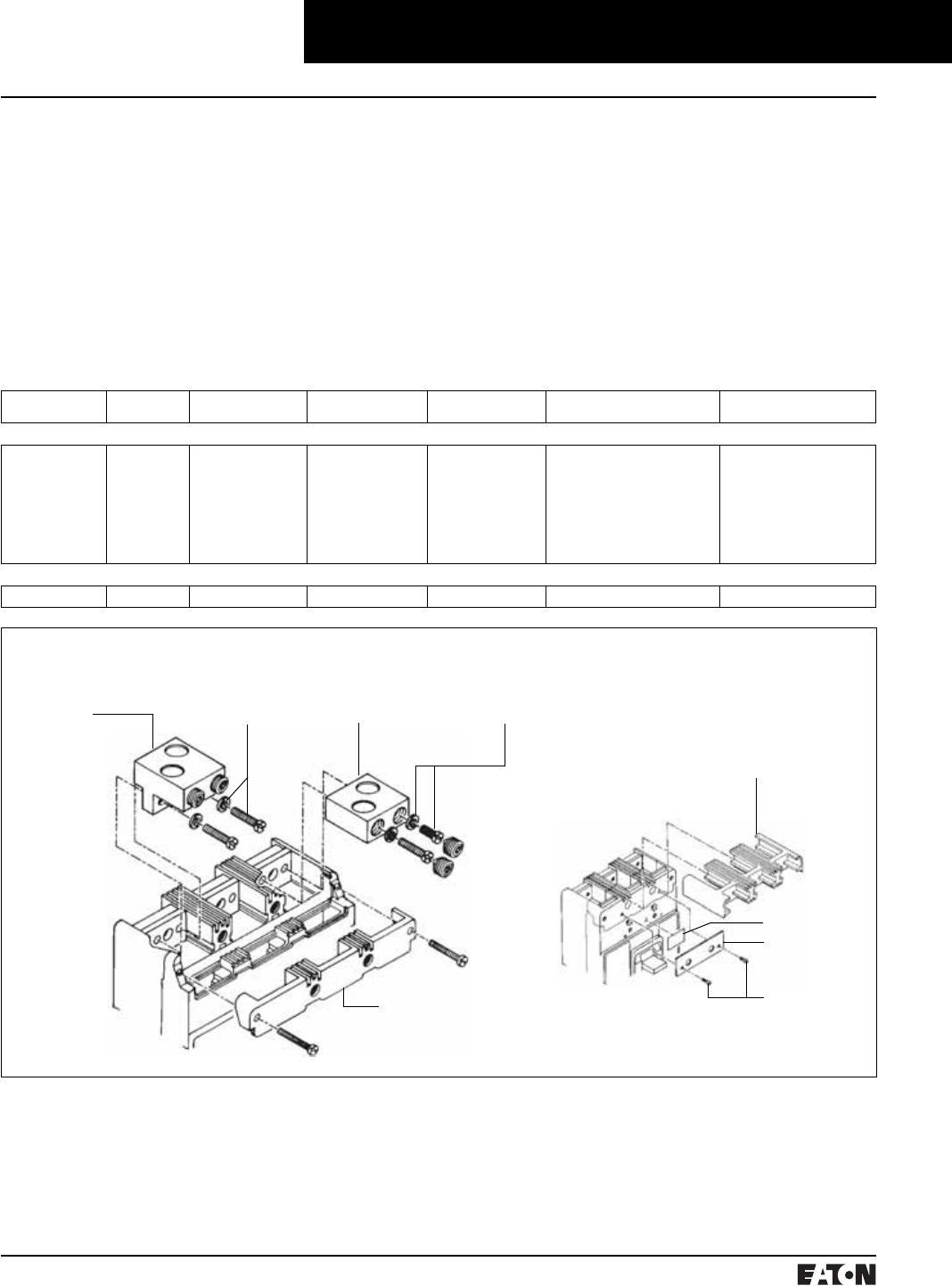
March 1999
PG.74A.01.T.E
Cutler-Hammer 63
Molded Case Circuit Breakers
125-600 Amperes
Series C L-Frame
Line and Load Terminals
Maximum Breaker
Amperes
Terminal Body
Material
Wire Type AWG Wire Range/
Number of Conductors
Metric Wire
Range mm2Terminal
Catalog Number
Terminals with Control Wire
Termination Catalog Numbers
Standard Cu/AI Pressure Terminals
400
450
500
600
Aluminum
Aluminum
Aluminum
Aluminum
Cu/AI
Cu/AI
Cu/AI
Cu/AI
4/0-600 (1)
4-4/0 (2)
3/0-350 (2)
400-500 (2)
120-300
25-95
95-150
185-240
2TA401LDK– 2-Pole Kit➀
3TA401LDK– 3-Pole Kit➀
4TA401LDK– 4-Pole Kit➀
TA450LD➁
TA602LD➁
2TA603LDK– 2-Pole Kit➀
3TA603LDK– 3-Pole Kit➀
4TA603LDK– 4-Pole Kit➀
–
–
–
–
TA602LDCW
2TA602LDKW
3TA602LDKW
4TA602LDKW
Optional Copper and Cu/AI Pressure Type Terminals
600 Copper Cu 250-500 (2) 120-250 T602LD➁–
Line and Load Terminals
Line and load terminals provide wire
connecting capabilities for specific
ranges of continuous current ratings
and wire types. All terminals comply
with Underwriters Laboratories, Inc.,
Standards UL486A and UL486B
and CSA Standard C22.2 No. 65M.
Unless otherwise specified, L-frame
circuit breaker line and load termi-
nals are shipped separately for field
installation.
The wire connecting terminal is
secured with two pan-head, slotted
screws and lock washers which can
be checked for the correct torque
loading or retightened from the
front of the circuit breaker before
installation of the conductors.
(Applies to all styles.) The circuit
breaker line/load terminal conduc-
tors are positioned in the conducting
holes in the wire connecting terminal
and are secured with recessed socket
screws which are tightened to the
correct torque loading from the front
of the circuit breaker.
Ordering Information
L-frame circuit breakers use Cu/AI
terminals as standard. When optional
copper terminals are required, order
by catalog number. Specify if factory
installation is required.
TA450LD or TA602LD
or T602LD Terminal
Pan-Head Screws and
Lockwashers (Installed
before Cable Clamping
Screws)
Terminal Cover
Screws
Retainer
➀Terminal kits contain one terminal for each
pole and one terminal cover.
➁Individually packed.
TA401LD or TA603LD
Terminal (Step-Type
Terminal Requires
Terminal Cover and
Warning Label.
See Inset.)
Pan-Head
Screws and
Lockwashers
Warning Label
Circuit Breaker
Line Terminal Cover
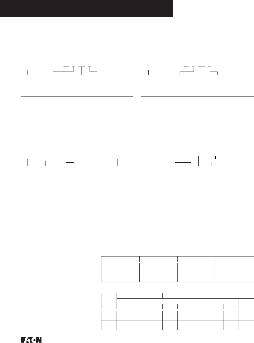
PG.74A.01.T.E
Cutler-Hammer
64 March 1999
Molded Case Circuit Breaker
125-600 Amperes
Series C L-Frame
Catalog Numbering System
This information is presented only as an aid to understanding catalog numbers. It is not to be used to build catalog
numbers for circuit breakers or trip units.
Thermal-Magnetic Trip Unit Catalog NumberCircuit Breaker/Frame Catalog Number
LD 3 600 F
Circuit
Breaker/
Frame
Type
LDB
LD
HLD
LDC
CLD
CHLD
CLDC
Number
of Poles
2: 2 Poles
3: 3 Poles
4: 4 Poles
Circuit
Breaker/
Frame
Ampere
Rating
300
350
400
450
500
600
Suffix
C: Copper Terminals
F: Frame Only
K: High Magnetic Molded
Case Switch
V: 50°C (Thermal-Mag-
netic Trip Units Only)
W: Without Terminals
X: Load Side
Terminals Only
Y: Line Side
Terminals Only
LT 3 400 T
Trip Unit
Type
LT: Thermal-
Magnetic
Number
of Poles
2: 2 Poles
3: 3 Poles
4: 4 Poles
Trip Unit/
Rating
Plug
Ampere
Rating
300
350
400
450
500
600
Suffix
T: Trip Unit
Thermal-Magnetic
Fixed Thermal
Adjustable Magnetic
V: 50°C Calibration
(Thermal-Magnetic
Trip Units Only)
OPTIM Circuit Breaker/Frame Catalog Number
LD 3 125 T5 7 W
Circuit
Breaker/
Frame
Type
LD
HLD
LDC
CLD
CHLD
CLDC
Number
of Poles
3: 3 Poles
Circuit
Breaker/
Frame
Ampere
Rating
125
(Available
on Model
750 and
1050 only)
250
(Available
on Model
750 and
1050 only)
400
600
Suffix
W: Without
Terminals
Trip
Type
2 – LSI
(550 only)
6 – LSIG
7 – LSIA
Trip
Model
T5 –
Model 550
T7 –
Model 750
T10 –
Model 1050
Digitrip RMS 310 Trip Unit Catalog Number
LES 3 600 LS P
Trip Unit
Type
LES: Electronic
Number
of Poles
3: 3 Poles
4: 4 Poles
Trip Unit
Ampere
Rating
600
Suffix
P: 100% Protected
Neutral on 4-Pole
Trip Unit
Suffix
LS
LSI
LSG
LSIG
Approximate Shipping Weight, Lbs. (kg)
Breaker
Type
Complete Breaker Frame Only Trip Unit
Number of Poles
234234234
LD, HLD,
LDC
18
(8.172)
20
(9.080)
25
(11.340)
14
(6.356)
15
(6.810)
20
(9.072)
3
(1.361)
4
(1.814)
5
(2.268)
LDB 18
(8.172)
20
(9.080)
25
(11.340)
––––––
Dimensions/Weights
Dimensions, Inches (mm)
Number of Poles Width Height Depth
2, 3 8.25
(210)
10.75
(274)
4.062
(103)
4 11
(279)
10.75
(274)
4.062
(103)

March 1999
PG.74A.01.T.E
Cutler-Hammer 65
Molded Case Circuit Breakers
125-600 Amperes
Series C L-Frame
➀2-pole breaker supplied in 3-pole frame.
Current carrying parts omitted from
center pole.
➁Refer to Cutler-Hammer for appropriate
neutral pole accessory combinations.
➂OPTIM models 750 and 1050 are factory
sealed and do not have the right pole space
available for accessories.
➃Shunt trip and UVR cannot be mounted in
right poles on LES trip units.
■Applicable in indicated pole position ❏May be mounted on left or right pole –
not both
●Accessory available/Modification available
Allowable Accessory Combinations
Different combinations of accessories can be supplied, depending on the types of accessories and the number of poles
in the circuit breaker.
Reference
Page
2-Pole➀, 3-Pole 4-Pole
Left Center Right Left Center Right Neu.➁
Internal Accessories (Only One Internal Accessory Per Pole)➂
Alarm Lockout (Make/Break) 140 ■■■■
Alarm Lockout (2Make/2Break) 140 ■■■■
Auxiliary Switch (1A, 1B) 143 ■■■■
Auxiliary Switch (2A, 2B) 143 ■■■■
Auxiliary Switch (3A, 3B) 143 ■■■■
Auxiliary Switch (1A, 1B) and Alarm Switch Combination 146 ■■■■
Auxiliary Switch (2A, 2B) and Alarm Switch Combination 146 ■■■■
Shunt Trip – Standard➃149 ■■■■
Shunt Trip – Low Energy➃152 ■■■■
Undervoltage Release Mechanism➃157 ■■■■
Cutler-Hammer PowerNet Communications Kit (OPTIM 550) 160 ■
External Accessories
End Cap Kit 161 ●●
Control Wire Terminal Kit 162 ●●
Base Mounting Hardware 163 ●●
Terminal Shields 165 ●●
Interphase Barriers 166 ●●
Non-Padlockable Handle Block 168 ■■
Padlockable Handle Lock Hasp 169 ❏❏❏❏
Key Interlock Kit 170 ❏❏❏❏
Sliding Bar Interlock – Requires Two Breakers 171 ●
Walking Beam Interlock – Requires Two Breakers 171 ●●
Electrical (Motor) Operator 173 ●●
Plug-in Adapters 174 ●●
Rear Connecting Studs 176 ●●
Panelboard Connecting Straps 177 ●●
Handle Mechanisms 178 ●●
Door Hardware/Accessories 182 ●●
Handle Extension 182 ●●
Solid-State (Electronic) Portable Test Kit 184 ●●
OPTIM System Components 3-Poles
Ground Fault Alarm Unit 184
Potential Transformer Module 184
Breaker Interface Module (BIM) 185
Digitrip OPTIMizer 185
Auxiliary Power Module 185
Cutler-Hammer PowerNet Software 185
Modifications (Refer to Cutler-Hammer)
Special Calibration 186 ●●
Moisture Fungus Treatment 186 ●●
Freeze-Tested Circuit Breakers 186 ●●
Marine Application 186 ●●

PG.74A.01.T.E
Cutler-Hammer
66 March 1999
Molded Case Circuit Breakers

March 1999
PG.74A.01.T.E
Cutler-Hammer 67
Molded Case Circuit Breakers
300-800 Amperes
Series C M-Frame
Typical Series C M-Frame Circuit Breaker
➀Utilization category A circuit breakers.
➁Two poles or two poles of 3-pole circuit
breaker. Thermal-magnetic trip units only,
MDL, HMDL breakers with electronic trip unit
are not DC rated.
➂Time constant is 3 milliseconds minimum at
10 kA and 8 milliseconds at 22 kA.
Interrupting Capacity Ratings
UL489/CSA Interrupting Capacity Ratings➀
Circuit
Breaker
Type
Number of
Poles
Interrupting Capacity (Symmetrical Amperes) (kA) Page
Number
Volts Ac (50/60 Hz) Volts Dc➁➂
240 480 600 250
MDL
CMDL
2, 3
2, 3
65
65
50
50
25
25
22
22
69, 70
70
HMDL
CHMDL
2, 3
2, 3
100
100
65
65
35
35
25
25
69, 70
70
IEC 947-2 Interrupting Capacity Ratings➀
Circuit
Breaker
Type
Number of
Poles
Interrupting Capacity – RMS Symmetrical Amperes (kA) ICU = ICS Page
Number
Volts Ac (50/60 Hz) Volts Dc➁➂
240 480 600 250
MDL
CMDL
2, 3
2, 3
85
85
50
50
20
20
20
20
69, 70
70
HMDL
CHMDL
2, 3
2, 3
100
100
65
65
25
25
20
20
69, 70
70
■All Series C M-frame circuit breakers
are HACR rated.
■MDL-frame circuit breakers are
available as individual compo-
nents (Frame, Trip Unit, Termi-
nals), or factory assembled
complete breakers.
■M-frame circuit breakers with
non-interchangeable trip units
are suitable for reverse feed use.
PG.74A.01.T.E
Cutler-Hammer
68 March 1999
Molded Case Circuit Breakers
300-800 Amperes
Series C M-Frame
➀Adjust by rating plug. In = Rating Plug
MDL-Frame Digitrip Selection Guide
Trip Unit Type Digitrip RMS 310
RMS Sensing Yes
Breaker Type
Frame MDL
Ampere Range 400-800A
Interrupting Rating @ 480V 50, 65 (kA)
Protection
Ordering Options LS, LSG LSI, LSIG
Fixed Rated Plug (In) Yes Yes
Overtemperature Trip Yes Yes
Long Delay Protection (L)
Adjustable Rating Plug (In) Yes Yes
Long Delay Pickup 0.5-1.0 (In) ➀0.5-1.0 (In) ➀
Long Delay Time I2T 12 Seconds 12 Seconds
Long Delay Time I4T No No
Long Delay Thermal Memory Yes Yes
High Load Alarm No No
Short Delay Protection (S)
Short Delay Pickup 200-800% x (In) 200-800% x (In)
Short Delay Time I2T 100 ms No
Short Delay Time Flat No Inst-300 ms
Short Delay Time Zone Selective Interlocking No No
Instantaneous Protection (I)
Instantaneous Pickup No 200-800% x (In)
Discriminator No No
Instantaneous Override Yes Yes
Ground Fault Protection (G)
Ground Fault Alarm No No
Ground Fault Pickup Varies by Frame Varies by Frame
Ground Fault Delay I2T No No
Ground Fault Delay Flat Inst-500 ms Inst-500 ms
Ground Fault Zone Selective Interlocking No No
Ground Fault Thermal Memory Yes Yes
System Diagnostics
Status LEDs Yes Yes
Cause of Trip LEDs No No
Magnitude of Trip Information No No
Remote Signal Contacts – Ground Alarm Yes Yes
System Monitoring
Digital Display No No
Current No No
Power and Energy No No
Power Quality – Harmonics No No
Power Factor No No
Communications
Cutler-Hammer PowerNet No No
Testing
Testing Method Test Set

March 1999
PG.74A.01.T.E
Cutler-Hammer 69
Molded Case Circuit Breakers
300-800 Amperes
Series C M-Frame
Types MDL and HMDL Thermal-Magnetic Circuit Breakers with Interchangeable Trip Units
Maximum
Continuous
Ampere
Rating
@ 40°C
Standard Interrupting Capacity
600 Vac Rated
50 kAIC @ 480 Vac
High Interrupting Capacity
600 Vac Rated
65 kAIC @ 480 Vac
Thermal Magnetic
Trip Unit Only
For Use With: Standard
or High or Ultra High
Interrupting Frames
Magnetic Trip Range is 5-10
up through 600A;
4-8 on 700 and 800A x Continuous
Ampere Rating
Standard Terminals Only ➀
See Page 72 for
Optional Terminals
Factory
Assembled
Circuit
Consisting
of Frame,
Trip Unit,
and Terminals
Frame
Only
Factory
Assembled
Circuit
Consisting
of Frame,
Trip Unit,
and Terminals
Frame
Only
Catalog Number
2-Pole
300
350
400
450
500
600
700
800
MDL2300
MDL2350
MDL2400
MDL2450
MDL2500
MDL2600
MDL2700
MDL2800
MDL2800F HMDL2300
HMDL2350
HMDL2400
HMDL2450
HMDL2500
HMDL2600
HMDL2700
HMDL2800
HMDL2800F MT2300T
MT2350T
MT2400T
MT2450T
MT2500T
MT2600T
MT2700T
MT2800T
TA700MA1
TA700MA1
TA700MA1
TA700MA1
TA700MA1
TA700MA1
TA700MA1
TA800MA2
3-Pole
300
350
400
450
500
600
700
800
MDL3300
MDL3350
MDL3400
MDL3450
MDL3500
MDL3600
MDL3700
MDL3800
MDL3800F HMDL3300
HMDL3350
HMDL3400
HMDL3450
HMDL3500
HMDL3600
HMDL3700
HMDL3800
HMDL3800F MT3300T
MT3350T
MT3400T
MT3450T
MT3500T
MT3600T
MT3700T
MT3800T
TA700MA1
TA700MA1
TA700MA1
TA700MA1
TA700MA1
TA700MA1
TA700MA1
TA800MA2
Instruction Leaflet/FRED Number 29C111 for Breaker
Types MDLB and HMDLB Thermal-Magnetic Circuit Breakers with Non-Interchangeable Trip Units
Maximum Continuous
Ampere Rating
@ 40°C
Standard Interrupting Capacity
600 Vac Rated
50 kAIC @ 480 Vac
High Interrupting Capacity
600 Vac Rated
50 kAIC @ 480 Vac
Standard Terminals Only ➀
See Page 72 for
Optional Terminals
Factory Assembled Circuit
Consisting of Frame, Trip Unit,
and Terminals
Factory Assembled Circuit
Consisting of Frame, Trip Unit,
and Terminals
Catalog Number
2-Pole
300
350
400
450
500
600
700
800
MDLB2300
MDLB2350
MDLB2400
MDLB2450
MDLB2500
MDLB2600
MDLB2700
MDLB2800
HMDLB2300
HMDLB2350
HMDLB2400
HMDLB2450
HMDLB2500
HMDLB2600
HMDLB2700
HMDLB2800
TA700MA1
TA700MA1
TA700MA1
TA700MA1
TA700MA1
TA700MA1
TA700MA1
TA800MA2
3-Pole
300
350
400
450
500
600
700
800
MDLB3300
MDLB3350
MDLB3400
MDLB3450
MDLB3500
MDLB3600
MDLB3700
MDLB3800
HMDLB3300
HMDLB3350
HMDLB3400
HMDLB3450
HMDLB3500
HMDLB3600
HMDLB3700
HMDLB3800
TA700MA1
TA700MA1
TA700MA1
TA700MA1
TA700MA1
TA700MA1
TA700MA1
TA800MA2
➀Two terminals are required per pole.
Instruction Leaflet/FRED Number 29C111 for Breaker
Time/Current Curves, Dimension Sheets, Application Data
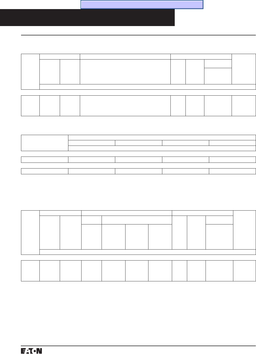
PG.74A.01.T.E
Cutler-Hammer
70 March 1999
Molded Case Circuit Breakers
300-800 Amperes
Series C M-Frame
Types MDL and HMDL Electronic Circuit Breakers with Interchangeable Trip Units
Order as Individual Components: Breaker Frame, Trip Unit, Rating Plug, Terminals.
Maximum
Continuous
Ampere
Rating
@ 40°C➀
Circuit Breaker Frame Only Digitrip RMS 310 Trip Unit Only➁ Digitrip RMS 310 Rating Plug Only Terminals
Standard
Interrupting
Capacity
600 Vac
Rated
35 kAIC @
480 Vac
High
Interrupting
Capacity
600 Vac
Rated
65 kAIC @
480 Vac
L – Adjustable Long Delay Pickup (by Adjustable Rating Plug)
S – Adjustable Short Delay Pickup with Fixed Short Delay Time (I2t
Response) or Adjustable Short Delay Time (Flat Response)
I – Adjustable Instantaneous Pickup by Setting Short Delay Time to
Instantaneous
G – Adjustable Ground Fault Pickup with Adjustable Ground Fault
Delay (Flat Response)
Ampere
Rating
Fixed
Rating
Plug
Adjustable
Rating Plugs
Ampere
Rating
Catalog
Number
Catalog Number
3-Pole
800 MDL3800F HMDL3800F MES3800LS
MES3800LSI
MES3800LSG
MES3800LSIG
400
500
600
700
800
8MES400T
8MES500T
8MES600T
8MES700T
8MES800T
400/500/600/800
A8MES800T
See Page 72
for Standard
and Optional
Terminals
➀Ampere rating is established by rating plug.
➁For Ac use only.
Instruction Leaflet/FRED Number 29C111 for Breaker; 29C615 for MES Trip Unit
Types MDLB and HMDLB Electronic Circuit Breakers with Non-Interchangeable Trip Units
Maximum
Continuous Ampere
Rating @ 40°C➀
Factory Assembled Circuit Breaker Consisting of Frame and Trip Unit
LS LSI LSG LSIG
Catalog Number
3-Pole Standard Interrupting Capacity 600 Vac Rated 50 kAIC @ 480 Vac
800 MDLB3800T33W MDLB3800T32W MDLB3800T35W MDLB3800T36W
3-Pole High Interrupting Capacity 600 Vac Rated 65 kAIC @ 480 Vac
800 HMDLB3800T33W HMDLB3800T32W HMDLB3800T35W HMDLB3800T36W
Instruction Leaflet/FRED Number 29C111 for Breaker; 29C615 for MES Trip Unit
100% Rated Types CMDL and CHMDL Electronic Circuit Breakers with Non-Interchangeable Trip Units
The NEC allows the breaker to be rated at 100% of its frame size in an assembly, provided that 90°C wire is applied at
the 75°C ampacity. All 100% rated circuit breakers have electronic trip units. Order as individual components: breaker
frame, trip unit, rating plug and terminals.
Maximum
Continuous
Ampere
Rating
@ 40°C➀
Circuit Breaker Frame Only Digitrip RMS 310 Trip Unit Only➁ Digitrip RMS 310 Trip Unit Only Terminals
Standard
Interrupting
Capacity
50 kAIC @
480 Vac
High
Interrupting
Capacity
50 kAIC @
480 Vac
Standard Options Ampere
Rating
Fixed
Rating
Plug
Adjustable
Rating Plug
Adjustable
Short Time
Delay with
I2t Short
Delay Ramp
Independently
Adjustable
Short Time
Pickup and
Delay
Ground Fault
Protection
Adjustable
Short Time
Pickup with
I2t Short
Delay and
Ground Fault
Protection
Independently
Adjustable
Short Time
Pickup and
Ground Fault
Protection
Ampere
Rating
Catalog
Number
Catalog Number
3-Pole
800 CMDL3800F CHMDL3800F MES3800LS MES3800LSI MES3800LSG MES3800LSIG 400
500
600
700
800
8MES400T
8MES500T
8MES600T
8MES700T
8MES800T
400/500/600/800
A8MES800T
See Page 72
for Standard
and Optional
Terminals
Instruction Leaflet/FRED Number 29C111 for Breaker; 29C615 for MES Trip Unit
Time/Current Curves, Dimension Sheets, Application Data
March 1999
PG.74A.01.T.E
Cutler-Hammer 71
Molded Case Circuit Breakers
300-800 Amperes
Series C M-Frame
Note: Molded case switch may trip above
6000 amperes.
Molded Case Switches
Molded case switches are used as compact switches in
applications requiring high current switching capabilities.
Molded case switches are constructed of circuit breaker
components and are of the high instantaneous automatic
type. Molded case switches are listed in accordance with
Underwriters Laboratories, Inc., Standard UL 1087.
Maximum Continuous
Ampere Rating
@ 40°C
600 Vac Maximum,
250 Vdc
Circuit Breaker Only without Line and
Load Terminals
Catalog Number
2-Pole
800 MDL2800WK
3-Pole
800 MDL3800WK
Instruction Leaflet/FRED Number 29C111
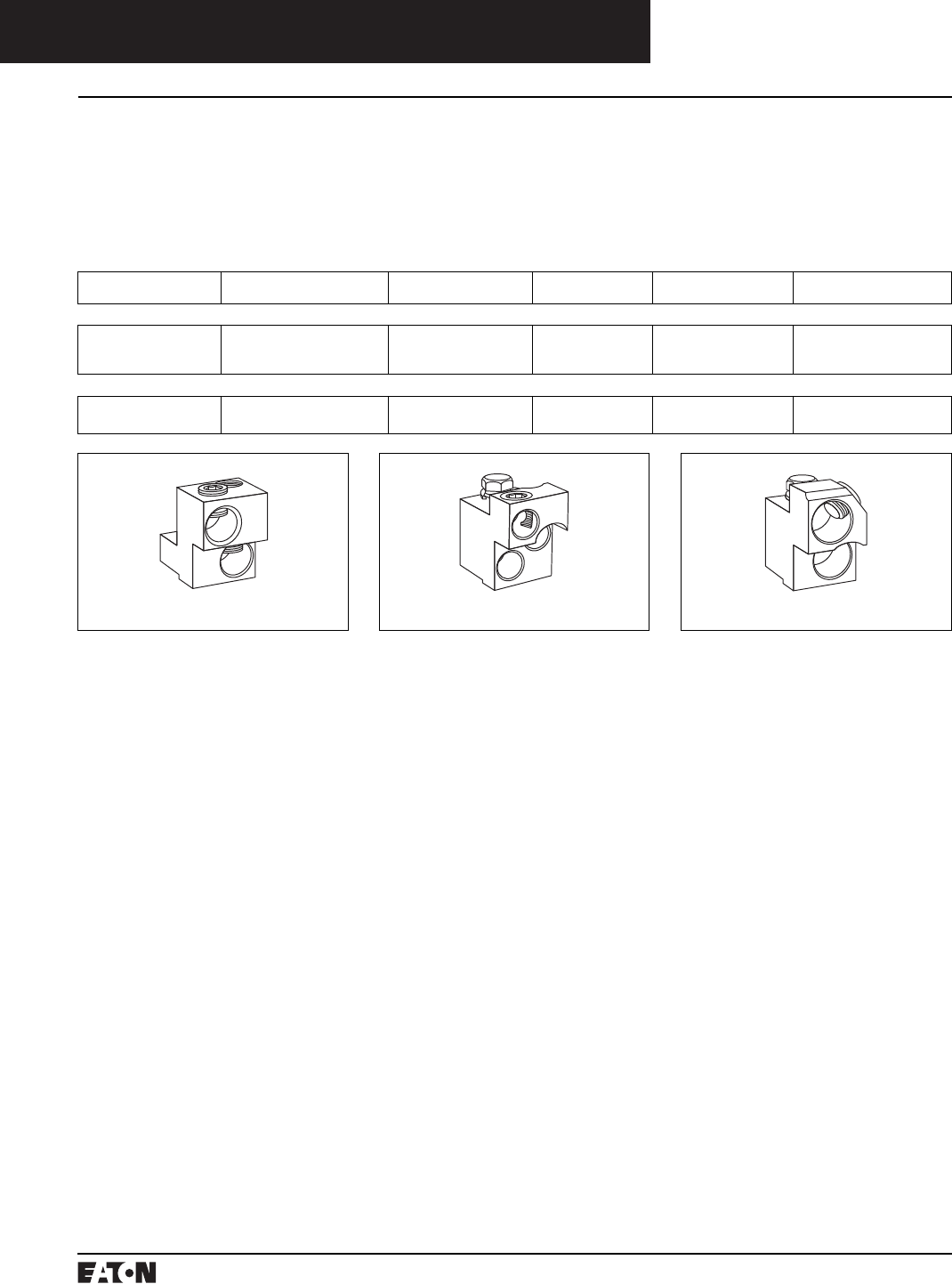
PG.74A.01.T.E
Cutler-Hammer
72 March 1999
Molded Case Circuit Breakers
300-800 Amperes
Series C M-Frame
Line and Load Terminals
M-Frame circuit breakers use Cu/AI
terminals as standard. When optional
copper or Cu/AI terminals are required,
order by catalog number. Specify if
factory installation is required.
Line and Load Terminals
Maximum Breaker
Amperes
Terminal Body
Material
Wire Type AWG Wire Range/
No. Conductors
Terminal
Catalog Number
Terminals with Control Wire
Termination Catalog Number
Standard Cu/AI Pressure Terminals
600
800
800
Aluminum
Aluminum
Aluminum
Cu/AI
Cu/AI
Cu/AI
(2) #1-500 kcmil
(3) 3/0-400 kcmil
(2) 500-750 kcmil
TA700MA1
TA800MA2
TA801MA
TA700MA1CWT
TA800MA2CWT
TA801MACWT
Optional Copper and Cu/AI Pressure Type Terminals
600
800
Copper
Copper
Cu
Cu
(2) 2/0-500 kcmil
(3) 3/0-300 kcmil
T600MA1
T800MA1
–
–
TA700MA1 TA800MA2 TA801MA1
March 1999
PG.74A.01.T.E
Cutler-Hammer 73
Molded Case Circuit Breakers
300-800 Amperes
Series C M-Frame
Approximate Shipping Weight, Lbs. (kg)
Breaker
Type
Complete Breaker Frame Only Trip Unit➀
Number of Poles
232323
MDL, HMDL
(T/M T.U.)
26.5 29 24.5 26 2.5 3
MDL, HMDL
(Elec. T.U.)
–30–26– 4
Dimensions/Weights
Dimensions, Inches (mm)
Number of Poles Width Height Depth
2, 3 8.250
(210)
16.000
(406)
4.062
(103)
Catalog Numbering System
This information is presented only as an aid to understanding catalog numbers. It is not to be used to build catalog
numbers for circuit breakers or trip units.
Thermal-Magnetic Trip Unit Catalog NumberCircuit Breaker/Frame Catalog Number
MDL 3 800 F
Circuit
Breaker/
Frame
Type
MDL
HMDL
Number
of Poles
2: 2 Poles
3: 3 Poles
Circuit
Breaker/
Frame
Ampere
Rating
300➀
350➀
400
450
500
600
700
800
Suffix
F: Frame Only
K: High Magnetic Molded
Case Switch
V: 50°C (Thermal-Mag-
netic Trip Units Only)
W: Without Terminals
X: Load Side
Terminals Only
Y: Line Side
Terminals Only
MT 3 800 T
Trip Unit
Type
MT:
MES:
Number
of Poles
2: 2 Poles
3: 3 Poles
Trip Unit/
Rating
Plug
Ampere
Rating
300➀
350➀
400
450
500
600
700
800
Suffix
T: Thermal-Magnetic
V: 50°C (Thermal-Mag-
netic Trip Units Only)
LS: Digitrip RMS 310
LSI: Digitrip RMS 310
LSG: Digitrip RMS 310
LSIG: Digitrip RMS 310
➀Thermal-Magnetic only.

PG.74A.01.T.E
Cutler-Hammer
74 March 1999
Molded Case Circuit Breakers
300-800 Amperes
Series C M-Frame
Allowable Accessory Combinations
Different combinations of accessories can be supplied, depending on the types of accessories and the number of poles
in the circuit breaker.
Reference
Page
2-Pole➀ 3-Pole
Left Right Left Center Right
Internal Accessories (Only One Internal Accessory Per Pole)
Alarm Lockout (Make/Break) 140 ■■■
Alarm Lockout (2Make/2Break) 140 ■■■
Auxiliary Switch (1A, 1B) 143 ■■■
Auxiliary Switch (2A, 2B) 143 ■■■
Auxiliary Switch (3A, 3B) 143 ■■■
Auxiliary Switch (1A, 1B) and Alarm Switch Combination 146 ■■■
Auxiliary Switch (2A, 2B) and Alarm Switch Combination 146 ■■■
Shunt Trip – Standard➂ 149 ■■■
Shunt Trip – Low Energy➂ 152 ■■■
Undervoltage Release Mechanism➂ 157 ■■■
External Accessories
Base Mounting Hardware 163 ●
Terminal Shields 165 ●
Interphase Barriers 166 ●
Non-Padlockable Handle Block 168 ■
Padlockable Handle Lock Hasp 169 ❏❏❏
Key Interlock Kit 170 ❏❏❏
Sliding Bar Interlock – Requires Two Breakers 171 ●●
Walking Beam Interlock – Requires Two Breakers 171 ●●
Electrical (Motor) Operator 173 ●●
Plug-in Adapters 174 ●●
Rear Connecting Studs 176 ●●
Panelboard Connecting Straps 177 ●●
Handle Mechanisms 178 ●●
Door Hardware/Accessories 182 ●●
Handle Extension 182 ●
Solid-State (Electronic) Portable Test Kit 184 ●●
Modifications (Refer to Cutler-Hammer)
Special Calibration 186 ●●
Moisture Fungus Treatment 186 ●●
Freeze-Tested Circuit Breakers 186 ●●
Marine Application 186 ●●
➀2-pole breaker supplied in 3-pole frame. Cur-
rent carrying parts omitted from center pole.
➁Refer to Cutler-Hammer for appropriate
neutral pole accessory combinations.
➂Shunt trip and UVR cannot be mounted in
right poles on LES trip units.
■Applicable in indicated pole position ❏May be mounted on left or right pole –
not both
●Accessory available/Modification available
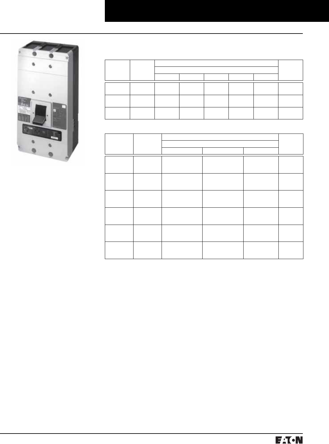
March 1999
PG.74A.01.T.E
Cutler-Hammer 75
Molded Case Circuit Breakers
400-1200 Amperes
Series C N-Frame
Typical Series C N-Frame Circuit Breaker
➀Utilization Category A circuit breakers.
➁100% rated breakers.
Interrupting Capacity Ratings
UL489 Interrupting Capacity Ratings➀
Circuit
Breaker
Type
Number
of Poles
Interrupting Capacity (Symmetrical Amperes) (kA) Page
Number
Volts Ac (50/60 Hz)
240 277 480 600 125
ND
CND➁
2, 3, 4
2, 3, 4
65
65
–
–
50
50
25
25
–
–
77, 83
80, 84
HND
CHND➁
2, 3, 4
2, 3, 4
100
100
–
–
65
65
35
35
–
–
78, 83
81, 84
NDC
CNDC➁
2, 3, 4
2, 3, 4
200
200
–
–
100
100
50
50
–
–
79, 83
82, 84
IEC 947-2 Interrupting Capacity Ratings➀
Circuit
Breaker
Type
Number of
Poles
Interrupting Capacity (Symmetrical Amperes) (kA) Page
Number
Volts Ac (50/60 Hz)
240 415 690
ND
Icu
Ics
2, 3, 4
85
85
50
50
20
10
77, 83
CND➁
Icu
Ics
2, 3, 4
85
85
50
50
20
10
80, 84
HND
Icu
Ics
2, 3, 4
100
100
70
50
25
13
78, 83
CHND➁
Icu
Ics
2, 3, 4
100
100
70
50
25
13
81, 84
NDC
Icu
Ics
2, 3, 4
200
100
100
50
35
18
79, 83
CNDC➁
Icu
Ics
2, 3, 4
200
100
100
50
35
18
82, 84
■All N-frame circuit breakers are
suitable for reverse feed use.
PG.74A.01.T.E
Cutler-Hammer
76 March 1999
Molded Case Circuit Breakers
400-1200 Amperes
Series C N-Frame
➀Adjust by rating plug.
➁By OPTIMizer/BIM.
➂Cutler-Hammer PowerNet kit for field upgrade.
BIM = Breaker Interface Module
(A) = GF Alarm
Is = Sensor Rating
In = Rating Plug
Ir = Long Delay Pickup Setting
N-Frame Digitrip Selection Guide
Trip Unit Type Digitrip RMS 310 Digitrip OPTIM 550 Digitrip OPTIM 750 Digitrip OPTIM 1050
RMS Sensing Yes Yes Yes Yes
Breaker Type
Frame N N N N
Ampere Range 400A-1200A 400A-1200A 400A-1200A 400A-1200A
Interrupting Rating @ 480V 50, 65, 100 (kA) 50, 65, 100 (kA) 50, 65, 100 (kA) 50, 65, 100 (kA)
Protection
Ordering Options LS, LSG LSI, LSIG LSI, LSIG, LSI(A) LSI(A), LSIG LSI(A), LISG
Fixed Rated Plug (In) Yes Yes Yes Yes Yes
Overtemperature Trip Yes Yes Yes Yes Yes
Long Delay Protection (L)
Adjustable Rating Plug (In) Yes Yes No No No
Long Delay Pickup 0.5-1.0 (In)➀0.5-1.0 (In)➀0.4-1.0 x (In) 0.4-1.0 x (In) 0.4-1.0 x (In)
Long Delay Time I2T 12 Seconds 12 Seconds 2-24 Seconds 2-24 Seconds 2-24 Seconds
Long Delay Time I4T No No 1-5 Seconds 1-5 Seconds 1-5 Seconds
Long Delay Thermal Memory Yes Yes Yes Yes Yes
High Load Alarm No No No 0.5-1.0 x Ir0.5-1.0 x Ir
Short Delay Protection (S)
Short Delay Pickup 200-800% x (In) 200-800% x (In) 150-800% x (Ir) 150-800% x (Ir) 150-800% x (Ir)
Short Delay Time I2T 100 ms No 100-500 ms 100-500 ms 100-500 ms
Short Delay Time Flat No Inst-300 ms 100-500 ms 100-500 ms 100-500 ms
Short Delay Time Zone Selective Interlocking No No Yes Yes Yes
Instantaneous Protection (I)
Instantaneous Pickup No 200-800% x (In) 200-800% x (In) 200-800% x (In) 200-800% x (In)
Discriminator No No Yes Yes Yes
Instantaneous Override Yes Yes Yes Yes Yes
Ground Fault Protection (G)
Ground Fault Alarm No No 20-100% x (Is) 20-100% x (Is) 20-100% x (Is)
Ground Fault Pickup Varies by Frame➁Varies by Frame➁20-100% x (Is) 20-100% x (Is) 20-100% x (Is)
Ground Fault Delay I2T No No 100-500 ms 100-500 ms 100-500 ms
Ground Fault Delay Flat Inst-500 ms Inst-500 ms 100-500 ms 100-500 ms 100-500 ms
Ground Fault Zone Selective Interlocking No No No Yes Yes
Ground Fault Thermal Memory Yes Yes Yes Yes Yes
System Diagnostics
Status LEDs Yes Yes Yes Yes Yes
Cause of Trip LEDs No No Yes Yes Yes
Magnitude of Trip Information No No Yes Yes Yes
Remote Signal Contact – Ground Alarm Yes Yes No Yes Yes
Local Auxiliary and Bell Alarm Contact Optional Optional Optional Included Included
System Monitoring
Digital Display No No Yes➁Yes➁Yes➁
Current No No Yes Yes Yes
Power and Energy No No No No Yes
Power Quality-Harmonics No No No No Yes
Power Factor No No No No Yes
Communications
Cutler-Hammer PowerNet No No No➂Yes Yes
Testing
Testing Method Test Set OPTIMizer, BIM, Cutler-
Hammer PowerNet
OPTIMizer, BIM, Cutler-
Hammer PowerNet
OPTIMizer, BIM, Cutler-
Hammer PowerNet

March 1999
PG.74A.01.T.E
Cutler-Hammer 77
Molded Case Circuit Breakers
400-1200 Amperes
Series C N-Frame
Type ND Electronic Circuit Breakers with Non-Interchangeable Trip Units
Order as individual components: Breaker Frame, Rating Plug, Terminals
Maximum
Continuous
Ampere
Rating
@ 40°C
Digitrip RMS 310 Circuit Breaker Frame Only Digitrip RMS 310 Rating Plug Only Standard Terminals Only➀
See Page 85 for
Optional Terminals
Standard Interrupting Capacity
600 Volt Ac Rated 50 kAIC @ 480 Vac
Ampere
Rating
Fixed
Rating
Plugs
Adjustable Rating Plug
Standard Options Adjustable Ampere Ratings
Catalog Number
Adjustable
Short Time
Delay with I2t
Short Delay
Ramp
Independently
Adjustable
Short Time
Pickup and
Delay
Adjustable
Short Time
Pickup with I2t
Short Delay and
Ground Fault
Protection
Independently
Adjustable
Short Time
Pickup and
Delay and
Ground Fault
Protection
Catalog Number
2-Pole
800 ND2800T33W ND2800T32W ND2800T35W ND2800T36W 400
450
500
600
700
800
8NES400T
8NES450T
8NES500T
8NES600T
8NES700T
8NES800T
Adjustable Settings are:
400, 500, 600, 800
A8NES800T1
TA700NB1
TA700NB1
TA700NB1
TA700NB1
TA700NB1
TA1000NB1
3-Pole
800 ND3800T33W ND3800T32W ND3800T35W ND3800T36W 400
450
500
600
700
800
8NES400T
8NES450T
8NES500T
8NES600T
8NES700T
8NES800T
Adjustable Settings are:
400, 500, 600, 800
A8NES800T1
TA700NB1
TA700NB1
TA700NB1
TA700NB1
TA700NB1
TA1000NB1
4-Pole➁
800 ND4800T33W ND4800T32W – – 400
450
500
600
700
800
8NES400T
8NES450T
8NES500T
8NES600T
8NES700T
8NES800T
Adjustable Settings are:
400, 500, 600, 800
A8NES800T1
TA700NB1
TA700NB1
TA700NB1
TA700NB1
TA700NB1
TA1000NB1
2-Pole
1200 ND212T33W ND212T32W ND212T35W ND212T36W 600
700
800
900
1000
1200
12NES600T
12NES700T
12NES800T
12NES900T
12NES1000T
12NES1200T
Adjustable Settings are:
600, 800, 1000, 1200
A12NES1200T1
TA700NB1
TA700NB1
TA1000NB1
TA1000NB1
TA1000NB1
TA1200NB1
3-Pole
1200 ND312T33W ND312T32W ND312T35W ND312T36W 600
700
800
900
1000
1200
12NES600T
12NES700T
12NES800T
12NES900T
12NES1000T
12NES1200T
Adjustable Settings are:
600, 800, 1000, 1200
A12NES1200T1
TA700NB1
TA700NB1
TA1000NB1
TA1000NB1
TA1000NB1
TA1200NB1
4-Pole➁
1200 ND412T33W ND412T32W – – 600
700
800
900
1000
1200
12NES600T
12NES700T
12NES800T
12NES900T
12NES1000T
12NES1200T
Adjustable Settings are:
600, 800, 1000, 1200
A12NES1200T1
TA700NB1
TA700NB1
TA1000NB1
TA1000NB1
TA1000NB1
TA1200NB1
Instruction Leaflet/FRED Number 29C106
➀Two terminals are required per pole.
➁Neutral is in right pole.
Time/Current Curves, Dimension Sheets, Application Data
PG.74A.01.T.E
Cutler-Hammer
78 March 1999
Molded Case Circuit Breakers
400-1200 Amperes
Series C N-Frame
Type HND Electronic Circuit Breakers with Non-Interchangeable Trip Units
Order as individual components: Breaker Frame, Rating Plug, Terminals
Maximum
Continuous
Ampere
Rating
@ 40°C
Digitrip RMS 310 Circuit Breaker Frame Only Digitrip RMS 310 Rating Plug Only Standard Terminals Only➀
See Page 85 for
Optional Terminals
High Interrupting Capacity
600 Volt Ac Rated 65 kAIC @ 480 Vac
Ampere
Rating
Fixed
Rating
Plugs
Adjustable Rating Plug
Standard Options Adjustable Ampere Ratings
Catalog Number
Adjustable
Short Time
Delay with I2t
Short Delay
Ramp
Independently
Adjustable
Short Time
Pickup and
Delay
Adjustable
Short Time
Pickup with I2t
Short Delay and
Ground Fault
Protection
Independently
Adjustable
Short Time
Pickup and
Delay and
Ground Fault
Protection
Catalog Number
2-Pole
800 HND2800T33W HND2800T32W HND2800T35W HND2800T36W 400
450
500
600
700
800
8NES400T
8NES450T
8NES500T
8NES600T
8NES700T
8NES800T
Adjustable Settings are:
400, 500, 600, 800
A8NES800T1
TA700NB1
TA700NB1
TA700NB1
TA700NB1
TA700NB1
TA1000NB1
3-Pole
800 HND3800T33W HND3800T32W HND3800T35W HND3800T36W 400
450
500
600
700
800
8NES400T
8NES450T
8NES500T
8NES600T
8NES700T
8NES800T
Adjustable Settings are:
400, 500, 600, 800
A8NES800T1
TA700NB1
TA700NB1
TA700NB1
TA700NB1
TA700NB1
TA1000NB1
4-Pole➁
800 HND4800T33W HND4800T32W – – 400
450
500
600
700
800
8NES400T
8NES450T
8NES500T
8NES600T
8NES700T
8NES800T
Adjustable Settings are:
400, 500, 600, 800
A8NES800T1
TA700NB1
TA700NB1
TA700NB1
TA700NB1
TA700NB1
TA1000NB1
2-Pole
1200 HND212T33W HND212T32W HND212T35W HND212T36W 600
700
800
900
1000
1200
12NES600T
12NES700T
12NES800T
12NES900T
12NES1000T
12NES1200T
Adjustable Settings are:
600, 800, 1000, 1200
A12NES1200T1
TA700NB1
TA700NB1
TA1000NB1
TA1000NB1
TA1000NB1
TA1200NB1
3-Pole
1200 HND312T33W HND312T32W HND312T35W HND312T36W 600
700
800
900
1000
1200
12NES600T
12NES700T
12NES800T
12NES900T
12NES1000T
12NES1200T
Adjustable Settings are:
600, 800, 1000, 1200
A12NES1200T1
TA700NB1
TA700NB1
TA1000NB1
TA1000NB1
TA1000NB1
TA1200NB1
4-Pole➁
1200 HND412T33W HND412T32W – – 600
700
800
900
1000
1200
12NES600T
12NES700T
12NES800T
12NES900T
12NES1000T
12NES1200T
Adjustable Settings are:
600, 800, 1000, 1200
A12NES1200T1
TA700NB1
TA700NB1
TA1000NB1
TA1000NB1
TA1000NB1
TA1200NB1
Instruction Leaflet/FRED Number 29C106
➀Two terminals are required per pole.
➁Neutral is in right pole.
Time/Current Curves, Dimension Sheets, Application Data

March 1999
PG.74A.01.T.E
Cutler-Hammer 79
Molded Case Circuit Breakers
400-1200 Amperes
Series C N-Frame
Type NDC Electronic Circuit Breakers with Non-Interchangeable Trip Units
Order as individual components: Breaker Frame, Rating Plug, Terminals
Maximum
Continuous
Ampere
Rating
@ 40°C
Digitrip RMS 310 Circuit Breaker Frame Only Digitrip RMS 310 Rating Plug Only Standard Terminals Only➀
See Page 85 for
Optional Terminals
Ultra High Interrupting Capacity
600 Volt Ac Rated 100 kAIC @ 480 Vac
Ampere
Rating
Fixed
Rating
Plugs
Adjustable Rating Plug
Standard Options Adjustable Ampere Ratings
Catalog Number
Adjustable
Short Time
Delay with I2t
Short Delay
Ramp
Independently
Adjustable
Short Time
Pickup and
Delay
Adjustable
Short Time
Pickup with I2t
Short Delay and
Ground Fault
Protection
Independently
Adjustable
Short Time
Pickup and
Delay and
Ground Fault
Protection
Catalog Number
2-Pole
800 NDC2800T33W NDC2800T32W NDC2800T35W NDC2800T36W 400
450
500
600
700
800
8NES400T
8NES450T
8NES500T
8NES600T
8NES700T
8NES800T
Adjustable Settings are:
400, 500, 600, 800
A8NES800T1
TA700NB1
TA700NB1
TA700NB1
TA700NB1
TA700NB1
TA1000NB1
3-Pole
800 NDC3800T33W NDC3800T32W NDC3800T35W NDC3800T36W 400
450
500
600
700
800
8NES400T
8NES450T
8NES500T
8NES600T
8NES700T
8NES800T
Adjustable Settings are:
400, 500, 600, 800
A8NES800T1
TA700NB1
TA700NB1
TA700NB1
TA700NB1
TA700NB1
TA1000NB1
4-Pole➁
800 NDC4800T33W NDC4800T32W – – 400
450
500
600
700
800
8NES400T
8NES450T
8NES500T
8NES600T
8NES700T
8NES800T
Adjustable Settings are:
400, 500, 600, 800
A8NES800T1
TA700NB1
TA700NB1
TA700NB1
TA700NB1
TA700NB1
TA1000NB1
2-Pole
1200 NDC212T33W NDC212T32W NDC212T35W NDC212T36W 600
700
800
900
1000
1200
12NES600T
12NES700T
12NES800T
12NES900T
12NES1000T
12NES1200T
Adjustable Settings are:
600, 800, 1000, 1200
A12NES1200T1
TA700NB1
TA700NB1
TA1000NB1
TA1000NB1
TA1000NB1
TA1200NB1
3-Pole
1200 NDC312T33W NDC312T32W NDC312T35W NDC312T36W 600
700
800
900
1000
1200
12NES600T
12NES700T
12NES800T
12NES900T
12NES1000T
12NES1200T
Adjustable Settings are:
600, 800, 1000, 1200
A12NES1200T1
TA700NB1
TA700NB1
TA1000NB1
TA1000NB1
TA1000NB1
TA1200NB1
4-Pole➁
1200 NDC412T33W NDC412T32W – – 600
700
800
900
1000
1200
12NES600T
12NES700T
12NES800T
12NES900T
12NES1000T
12NES1200T
Adjustable Settings are:
600, 800, 1000, 1200
A12NES1200T1
TA700NB1
TA700NB1
TA1000NB1
TA1000NB1
TA1000NB1
TA1200NB1
➀Two terminals are required per pole.
➁Neutral is in right pole.
Instruction Leaflet/FRED Number 29C106
Time/Current Curves, Dimension Sheets, Application Data

PG.74A.01.T.E
Cutler-Hammer
80 March 1999
Molded Case Circuit Breakers
400-1200 Amperes
Series C N-Frame
100% Rated Type CND Electronic Circuit Breakers with Non-Interchangeable Trip Units
The NEC allows the breaker to be rated at 100% of its frame size in an assembly, provided that 90°C wire is applied at
the 75°C ampacity. Order as individual components: Breaker Frame, Rating Plug, Terminals
Maximum
Continuous
Ampere
Rating
@ 40°C
Digitrip RMS 310 Circuit Breaker Frame Only Digitrip RMS 310 Rating Plug Only Standard Terminals Only➀
See Page 85 for
Optional Terminals
Standard Interrupting Capacity
600 Volt Ac Rated 50 kAIC @ 480 Vac
Ampere
Rating
Fixed
Rating
Plugs
Adjustable Rating Plug
Standard Options Adjustable Ampere Ratings
Catalog Number
Adjustable
Short Time
Delay with I2t
Short Delay
Ramp
Independently
Adjustable
Short Time
Pickup and
Delay
Adjustable
Short Time
Pickup with I2t
Short Delay and
Ground Fault
Protection
Independently
Adjustable
Short Time
Pickup and
Delay and
Ground Fault
Protection
Catalog Number
2-Pole
800 CND2800T33W CND2800T32W CND2800T35W CND2800T36W 400
450
500
600
700
800
8NES400T
8NES450T
8NES500T
8NES600T
8NES700T
8NES800T
Adjustable Settings are:
400, 500, 600, 800
A8NES800T1
TA700NB1
TA700NB1
TA700NB1
TA700NB1
TA700NB1
TA1000NB1
3-Pole
800 CND3800T33W CND3800T32W CND3800T35W CND3800T36W 400
450
500
600
700
800
8NES400T
8NES450T
8NES500T
8NES600T
8NES700T
8NES800T
Adjustable Settings are:
400, 500, 600, 800
A8NES800T1
TA700NB1
TA700NB1
TA700NB1
TA700NB1
TA700NB1
TA1000NB1
4-Pole➁
800 CND4800T33W CND4800T32W – – 400
450
500
600
700
800
8NES400T
8NES450T
8NES500T
8NES600T
8NES700T
8NES800T
Adjustable Settings are:
400, 500, 600, 800
A8NES800T1
TA700NB1
TA700NB1
TA700NB1
TA700NB1
TA700NB1
TA1000NB1
2-Pole
1200 CND212T33W CND212T32W CND212T35W CND212T36W 600
700
800
900
1000
1200
12NES600T
12NES700T
12NES800T
12NES900T
12NES1000T
12NES1200T
Adjustable Settings are:
600, 800, 1000, 1200
A12NES1200T1
TA700NB1
TA700NB1
TA1000NB1
TA1000NB1
TA1000NB1
TA1200NB1
3-Pole
1200 CND312T33W CND312T32W CND312T35W CND312T36W 600
700
800
900
1000
1200
12NES600T
12NES700T
12NES800T
12NES900T
12NES1000T
12NES1200T
Adjustable Settings are:
600, 800, 1000, 1200
A12NES1200T1
TA700NB1
TA700NB1
TA1000NB1
TA1000NB1
TA1000NB1
TA1200NB1
4-Pole➁
1200 CND412T33W CND412T32W – – 600
700
800
900
1000
1200
12NES600T
12NES700T
12NES800T
12NES900T
12NES1000T
12NES1200T
Adjustable Settings are:
600, 800, 1000, 1200
A12NES1200T1
TA700NB1
TA700NB1
TA1000NB1
TA1000NB1
TA1000NB1
TA1200NB1
Instruction Leaflet/FRED Number 29C106
➀Two terminals are required per pole.
➁Neutral is in right pole.
Time/Current Curves, Dimension Sheets, Application Data

March 1999
PG.74A.01.T.E
Cutler-Hammer 81
Molded Case Circuit Breakers
400-1200 Amperes
Series C N-Frame
100% Rated Type CHND Electronic Circuit Breakers with Non-Interchangeable Trip Units
The NEC allows the breaker to be rated at 100% of its frame size in an assembly, provided that 90°C wire is applied at
the 75°C ampacity. Order as individual components: Breaker Frame, Rating Plug, Terminals
Maximum
Continuous
Ampere
Rating
@ 40°C
Digitrip RMS 310 Circuit Breaker Frame Only Digitrip RMS 310 Rating Plug Only Standard Terminals Only➀
See Page 85 for
Optional Terminals
High Interrupting Capacity
600 Volt Ac Rated 65 kAIC @ 480 Vac
Ampere
Rating
Fixed
Rating
Plugs
Adjustable Rating Plug
Standard Options Adjustable Ampere Ratings
Catalog Number
Adjustable Short
Time Delay with
I2t Short Delay
Ramp
Independently
Adjustable Short
Time Pickup and
Delay
Adjustable Short
Time Pickup with
I2t Short Delay
and Ground Fault
Protection
Independently
Adjustable Short
Time Pickup and
Delay and Ground
Fault Protection
Catalog Number
2-Pole
800 CHND2800T33W CHND2800T32W CHND2800T35W CHND2800T36W 400
450
500
600
700
800
8NES400T
8NES450T
8NES500T
8NES600T
8NES700T
8NES800T
Adjustable Settings are:
400, 500, 600, 800
A8NES800T1
TA700NB1
TA700NB1
TA700NB1
TA700NB1
TA700NB1
TA1000NB1
3-Pole
800 CHND3800T33W CHND3800T32W CHND3800T35W CHND3800T36W 400
450
500
600
700
800
8NES400T
8NES450T
8NES500T
8NES600T
8NES700T
8NES800T
Adjustable Settings are:
400, 500, 600, 800
A8NES800T1
TA700NB1
TA700NB1
TA700NB1
TA700NB1
TA700NB1
TA1000NB1
4-Pole➁
800 CHND4800T33W CHND4800T32W – – 400
450
500
600
700
800
8NES400T
8NES450T
8NES500T
8NES600T
8NES700T
8NES800T
Adjustable Settings are:
400, 500, 600, 800
A8NES800T1
TA700NB1
TA700NB1
TA700NB1
TA700NB1
TA700NB1
TA1000NB1
2-Pole
1200 CHND212T33W CHND212T32W CHND212T35W CHND212T36W 600
700
800
900
1000
1200
12NES600T
12NES700T
12NES800T
12NES900T
12NES1000T
12NES1200T
Adjustable Settings are:
600, 800, 1000, 1200
A12NES1200T1
TA700NB1
TA700NB1
TA1000NB1
TA1000NB1
TA1000NB1
TA1200NB1
3-Pole
1200 CHND312T33W CHND312T32W CHND312T35W CHND312T36W 600
700
800
900
1000
1200
12NES600T
12NES700T
12NES800T
12NES900T
12NES1000T
12NES1200T
Adjustable Settings are:
600, 800, 1000, 1200
A12NES1200T1
TA700NB1
TA700NB1
TA1000NB1
TA1000NB1
TA1000NB1
TA1200NB1
4-Pole➁
1200 CHND412T33W CHND412T32W – – 600
700
800
900
1000
1200
12NES600T
12NES700T
12NES800T
12NES900T
12NES1000T
12NES1200T
Adjustable Settings are:
600, 800, 1000, 1200
A12NES1200T1
TA700NB1
TA700NB1
TA1000NB1
TA1000NB1
TA1000NB1
TA1200NB1
Instruction Leaflet/FRED Number 29C106
➀Two terminals are required per pole.
➁Neutral is in right pole.
Time/Current Curves, Dimension Sheets, Application Data

PG.74A.01.T.E
Cutler-Hammer
82 March 1999
Molded Case Circuit Breakers
400-1200 Amperes
Series C N-Frame
100% Rated Type CNDC Electronic Circuit Breakers with Non-Interchangeable Trip Units
The NEC allows the breaker to be rated at 100% of its frame size in an assembly, provided that 90°C wire is applied at
the 75°C ampacity. Order as individual components: Breaker Frame, Rating Plug, Terminals
Maximum
Continuous
Ampere
Rating
@ 40°C
Digitrip RMS 310 Circuit Breaker Frame Only Digitrip RMS 310 Rating Plug Only Standard Terminals Only➀
See Page 85 for
Optional Terminals
Ultra High Interrupting Capacity
600 Volt Ac Rated 100 kAIC @ 480 Vac
Ampere
Rating
Fixed
Rating
Plugs
Adjustable Rating Plug
Standard Options Adjustable Ampere Ratings
Catalog Number
Adjustable Short
Time Delay with
I2t Short Delay
Ramp
Independently
Adjustable Short
Time Pickup and
Delay
Adjustable Short
Time Pickup with
I2t Short Delay
and Ground Fault
Protection
Independently
Adjustable Short
Time Pickup and
Delay and Ground
Fault Protection
Catalog Number
2-Pole
800 CNDC2800T33W CNDC2800T32W CNDC2800T35W CNDC2800T36W 400
450
500
600
700
800
8NES400T
8NES450T
8NES500T
8NES600T
8NES700T
8NES800T
Adjustable Settings are:
400, 500, 600, 800
A8NES800T1
TA700NB1
TA700NB1
TA700NB1
TA700NB1
TA700NB1
TA1000NB1
3-Pole
800 CNDC3800T33W CNDC3800T32W CNDC3800T35W CNDC3800T36W 400
450
500
600
700
800
8NES400T
8NES450T
8NES500T
8NES600T
8NES700T
8NES800T
Adjustable Settings are:
400, 500, 600, 800
A8NES800T1
TA700NB1
TA700NB1
TA700NB1
TA700NB1
TA700NB1
TA1000NB1
4-Pole➁
800 CNDC4800T33W CNDC4800T32W – – 400
450
500
600
700
800
8NES400T
8NES450T
8NES500T
8NES600T
8NES700T
8NES800T
Adjustable Settings are:
400, 500, 600, 800
A8NES800T1
TA700NB1
TA700NB1
TA700NB1
TA700NB1
TA700NB1
TA1000NB1
2-Pole
1200 CNDC212T33W CNDC212T32W CNDC212T35W CNDC212T36W 600
700
800
900
1000
1200
12NES600T
12NES700T
12NES800T
12NES900T
12NES1000T
12NES1200T
Adjustable Settings are:
600, 800, 1000, 1200
A12NES1200T1
TA700NB1
TA700NB1
TA1000NB1
TA1000NB1
TA1000NB1
TA1200NB1
3-Pole
1200 CNDC312T33W CNDC312T32W CNDC312T35W CNDC312T36W 600
700
800
900
1000
1200
12NES600T
12NES700T
12NES800T
12NES900T
12NES1000T
12NES1200T
Adjustable Settings are:
600, 800, 1000, 1200
A12NES1200T1
TA700NB1
TA700NB1
TA1000NB1
TA1000NB1
TA1000NB1
TA1200NB1
4-Pole➁
1200 CNDC412T33W CNDC412T32W – – 600
700
800
900
1000
1200
12NES600T
12NES700T
12NES800T
12NES900T
12NES1000T
12NES1200T
Adjustable Settings are:
600, 800, 1000, 1200
A12NES1200T1
TA700NB1
TA700NB1
TA1000NB1
TA1000NB1
TA1000NB1
TA1200NB1
Instruction Leaflet/FRED Number 29C106
➀Two terminals are required per pole.
➁Neutral is in right pole.
Time/Current Curves, Dimension Sheets, Application Data
March 1999
PG.74A.01.T.E
Cutler-Hammer 83
Molded Case Circuit Breakers
400-1200 Amperes
Series C N-Frame
Digitrip OPTIM➀ Electronic Circuit Breakers with Interchangeable Rating Plugs
Order as individual components: Breaker Frame (which includes Trip Unit), Rating Plug, Terminals.
Maximum
Continuous
Ampere
Rating
@ 40°C
Circuit Breaker Frame Only Digitrip OPTIM Rating
Plug Only
L – Adjustable Long Delay Pickup (Ir) with Adjustable Long Delay Time (I2t or I4t Response)➁
S – Adjustable Short Delay Pickup with Adjustable Short Delay Time (I2t or Flat Response)
I – Adjustable Instantaneous Pickup
G – Adjustable Ground Fault Pickup with Adjustable Ground Fault Time Delay (I2t or Flat Response)
A – Adjustable Ground Fault Alarm with Adjustable Ground Fault Time Delay (I2t or Flat Response)
Ampere
Rating
Fixed
Rating
Plug
OPTIM 550 OPTIM 550 OPTIM 550 OPTIM 750 OPTIM 750 OPTIM 1050 OPTIM 1050
LSI LSIG LSIA LSIG LSIA LSIG LSIA
Catalog Number
3-Pole Standard Interrupting Capacity 600 Volt Ac Rated 50 kAIC @ 480 Vac
800 ND3800T52W ND3800T56W ND3800T57W ND3800T76W ND3800T77W ND3800T106W ND3800T107W 400
450
500
550
600
700
800
ORPN80A400
ORPN80A450
ORPN80A500
ORPN80A550
ORPN80A600
ORPN80A700
ORPN80A800
1200 ND312T52W ND312T56W ND312T57W ND312T76W ND312T77W ND312T106W ND312T107W 600
700
800
1000
1200
ORPN80A600
ORPN80A700
ORPN80A800
ORPN80A100
ORPN80A120
3-Pole High Interrupting Capacity 600 Volt Ac Rated 65 kAIC @ 480 Vac
800 HND3800T52W HND3800T56W HND3800T57W HND3800T76W HND3800T77W HND3800T106W HND3800T107W 400
450
500
550
600
700
800
ORPN80A400
ORPN80A450
ORPN80A500
ORPN80A550
ORPN80A600
ORPN80A700
ORPN80A800
1200 HND312T52W HND312T56W HND312T57W HND312T76W HND312T77W HND312T106W HND312T107W 600
700
800
1000
1200
ORPN80A600
ORPN80A700
ORPN80A800
ORPN80A100
ORPN80A120
3-Pole Ultra High Interrupting Capacity 600 Volt Ac Rated 100 kAIC @ 480 Vac
800 NDC3800T52W NDC3800T56W NDC3800T57W NDC3800T76W NDC3800T77W NDC3800T106W NDC3800T107W 400
450
500
550
600
700
800
ORPN80A400
ORPN80A450
ORPN80A500
ORPN80A550
ORPN80A600
ORPN80A700
ORPN80A800
1200 NDC312T52W NDC312T56W NDC312T57W NDC312T76W NDC312T77W NDC312T106W NDC312T107W 600
700
800
1000
1200
ORPN80A600
ORPN80A700
ORPN80A800
ORPN80A100
ORPN80A120
Instruction Leaflet/FRED Number 29C106 for Breaker; 29C891 for OPTIM Trip
➀1 Form C auxiliary switch and 1 Form C bell
(trip) alarm switch supplied with breaker as
standard on models 750 and 1050.
➁Long delay I4t response selection limits short
delay time to flat response.
Time/Current Curves, Dimension Sheets, Application Data

PG.74A.01.T.E
Cutler-Hammer
84 March 1999
Molded Case Circuit Breakers
400-1200 Amperes
Series C N-Frame
100% Rated Digitrip OPTIM➀ Circuit Breakers with Interchangeable Rating Plugs
Order as individual components: Breaker Frame (which includes Trip Unit), Rating Plug, Terminals.
Maximum
Continuous
Ampere
Rating
@ 40°C
Circuit Breaker Frame Only Digitrip OPTIM Rating
Plug Only
L – Adjustable Long Delay Pickup (Ir) with Adjustable Long Delay Time (I2t or I4t Response)➁
S – Adjustable Short Delay Pickup with Adjustable Short Delay Time (I2t or Flat Response)
I – Adjustable Instantaneous Pickup
G – Adjustable Ground Fault Pickup with Adjustable Ground Fault Time Delay (I2t or Flat Response)
A – Adjustable Ground Fault Alarm with Adjustable Ground Fault Time Delay (I2t or Flat Response)
Ampere
Rating
Fixed
Rating
Plug
OPTIM 550 OPTIM 550 OPTIM 550 OPTIM 750 OPTIM 750 OPTIM 1050 OPTIM 1050
LSI LSIG LSIA LSIG LSIA LSIG LSIA
Catalog Number
3-Pole Standard Interrupting Capacity 600 Volt Ac Rated 50 kAIC @ 480 Vac
800
CND3800T52W CND3800T56W CND3800T57W CND3800T76W CND3800T77W CND3800T106W CND3800T107W
400
450
500
550
600
700
800
ORPN80A400
ORPN80A450
ORPN80A500
ORPN80A550
ORPN80A600
ORPN80A700
ORPN80A800
1200
CND312T52W CND312T56W CND312T57W CND312T76W CND312T77W CND312T106W CND312T107W
600
700
800
1000
1200
ORPN80A600
ORPN80A700
ORPN80A800
ORPN80A100
ORPN80A120
3-Pole High Interrupting Capacity 600 Volt Ac Rated 65 kAIC @ 480 Vac
800
CHND3800T52W CHND3800T56W CHND3800T57W CHND3800T76W CHND3800T77W CHND3800T106W CHND3800T107W
400
450
500
550
600
700
800
ORPN80A400
ORPN80A450
ORPN80A500
ORPN80A550
ORPN80A600
ORPN80A700
ORPN80A800
1200
CHND312T52W CHND312T56W CHND312T57W CHND312T76W CHND312T77W CHND312T106W CNHD312T107W
600
700
800
1000
1200
ORPN80A600
ORPN80A700
ORPN80A800
ORPN80A100
ORPN80A120
3-Pole Ultra High Interrupting Capacity 600 Volt Ac Rated 100 kAIC @ 480 Vac
800
CNDC3800T52W CNDC3800T56W CNDC3800T57W CNDC3800T76W CNDC3800T77W CNDC3800T106W CNDC3800T107W
400
450
500
550
600
700
800
ORPN80A400
ORPN80A450
ORPN80A500
ORPN80A550
ORPN80A600
ORPN80A700
ORPN80A800
1200
CNDC312T52W CNDC312T56W CNDC312T57W CNDC312T76W CNDC312T77W CNDC312T106W CNDC312T107W
600
700
800
1000
1200
ORPN80A600
ORPN80A700
ORPN80A800
ORPN80A100
ORPN80A120
Instruction Leaflet/FRED Number 29C106 for Breaker; 29C891 for OPTIM Trip
➀1 Form C auxiliary switch and 1 Form C bell
(trip) alarm switch supplied with breaker as
standard on models 750 and 1050.
➁Long delay I4t response selection limits short
delay time to flat response.
Time/Current Curves, Dimension Sheets, Application Data
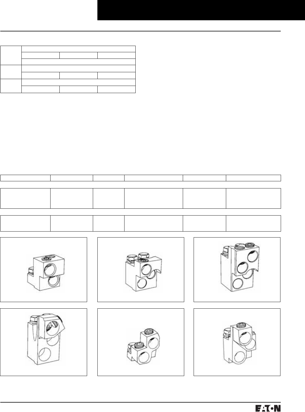
March 1999
PG.74A.01.T.E
Cutler-Hammer 85
Molded Case Circuit Breakers
400-1200 Amperes
Series C N-Frame
T1000NB1
Note: Molded case switch may trip above 14,000 amperes.
For UL listed, series tested molded case switch applica-
tion data, refer to Cutler-Hammer.
Instruction Leaflet/FRED Number 29C106
Type ND Molded Case Switches
Continuous
Ampere
Rating
@ 40°C
Catalog Number
2-Pole 3-Pole 4-Pole➀
Complete with Standard Line and Load Terminals (shipped separately)
Type ND – HIgh Instantaneous (K)
800 – ND3800WK ND4800WK
Type ND – HIgh Instantaneous (K)
1200 – ND312WK ND412WK
➀Neutral is in right pole.
➁Terminal rating is A19 Cu.
➂Terminal rating is A17 Cu.
Line and Load Terminals
Ordering Information
N-frame circuit breakers use Cu/AI terminals as standard. When optional copper or Cu/AI terminals are required, order
by catalog number. Specify if factory installation is required.
Line and Load Terminals
Maximum Breaker Amperes Terminal Body Material Wire Type AWG Wire Range/No. Conductors Metric Wire Range mm2Catalog Number
Standard Cu/AI Pressure Terminals
700
1000
1200
1200
Aluminum
Aluminum
Aluminum
Aluminum
Cu/AI
Cu/AI
Cu/AI
Cu/AI
(2) 1-500 kcmil
(3) 3/0-400 kcmil
(4) 4/0-500 kcmil
(3) 500-750 kcmil
50-300
95-185
120-300
300-400
TA700NB1
TA1000NB1➁
TA1200NB1➁
TA1201NB1➂
Optional Copper and Cu/AI Pressure Type Terminals
700
1000
1200
Copper
Copper
Copper
Cu
Cu
Cu
(2) 2/0-500 kcmil
(3) 3/0-500 kcmil
(4) 3/0-400 kcmil
70-300
95-300
95-185
T700NB1
T1000NB1
T1200NB3
TA700NB1 TA1000NB1 TA1200NB1
TA1201NB1 T700NB1

PG.74A.01.T.E
Cutler-Hammer
86 March 1999
Molded Case Circuit Breakers
400-1200 Amperes
Series C N-Frame
Dimensions/Weights
Dimensions, Inches (mm)
Number of Poles Width Height Depth
2, 3 8.25
(210)
16
(407)
5.5
(140)
4 11.125
(283)
16
(407)
5.5
(140)
Approximate Shipping Weight, Lbs. (kg)
Breaker Type Complete Breaker
Number of Poles
234
ND, HND, NDC 37
(16.783)
45
(20.412)
58
(26.308)
Catalog Numbering System
This information is presented only as an aid to understanding catalog numbers. It is not to be used to build catalog
numbers for circuit breakers or trip units.
Circuit Breaker/Frame Catalog Number
ND 3 12 T3 2 W
Circuit Breaker/
Frame Type
ND
HND
NDC
CND
CHND
CNDC
Number
of Poles
2: 2 Poles
3: 3 Poles
4: 4 Poles
Circuit Breaker/
Frame Ampere
Rating
8: 800 Amperes
12: 1200 Amperes
Suffix
E: 100% R.P. protected (4-Pole)
EH: 50% R.P. protected (4-Pole)
K: High Magnetic Molded
Case Switch
W: Without Terminals
X: Load Only Terminals
Y: Line Only Terminals
Trip Model
T3 – Model 310
T5 – Model 550
T7 – Model 750
T10 – Model 1050
Trip Type
2 – LSI
3 – LS
5 – LSG
6 – LSIG
7 – LSIA

March 1999
PG.74A.01.T.E
Cutler-Hammer 87
Molded Case Circuit Breakers
400-1200 Amperes
Series C N-Frame
Allowable Accessory Combinations
Different combinations of accessories can be supplied, depending on the types of accessories and the number of poles
in the circuit breaker.
Reference
Page
3-Pole 4-Pole
Left Center Right Left Center Right Neu.
Internal Accessories (Only One Internal Accessory Per Pole)➀
Alarm Lockout (Make/Break) 141 ■■■■
Alarm Lockout (2Make/2Break) 141 ■■■■
Auxiliary Switch (1A, 1B) 144 ■■■■
Auxiliary Switch (2A, 2B) 144 ■■■■
Auxiliary Switch (3A, 3B) 144 ■■■■
Auxiliary Switch (1A 1B) and Alarm Switch Combination 146 ■■■■
Auxiliary Switch (2A 2B) and Alarm Switch Combination 146 ■■■■
Shunt Trip – Standard 150 ■■
Shunt Trip – Low Energy 152 ■■
Undervoltage Release Mechanism 158 ■■
Cutler-Hammer PowerNet Communications Kit (OPTIM 550) 160 ■
External Accessories
Base Mounting Hardware 163 ●●
Interphase Barriers 166 ●●
Non-Padlockable Handle Block 168 ■■
Padlockable Handle Lock Hasp 169 ❏❏❏❏
Key Interlock Kit 170 ❏❏❏❏
Sliding Bar Interlock – Requires Two Breakers 171 ●
Walking Beam Interlock – Requires Two Breakers 171 ●●
Electrical (Motor) Operator 173 ●●
Plug-in Adapters 174 ●●
Rear Connecting Studs 176 ●●
Panelboard Connecting Straps 177 ●●
Handle Mechanisms 178 ●●
Handle Extension 182 ●●
Solid-State (Electronic) Portable Test Kit 184 ●●
OPTIM System Components 3-Poles
Ground Fault Alarm Unit 184
Potential Transformer Module 184
Breaker Interface Module (BIM) 185
Digitrip OPTIMizer 185
Auxiliary Power Module 185
Cutler-Hammer PowerNet Software 185
Modifications (Refer to Cutler-Hammer)
Special Calibration 186 ●●
Moisture Fungus Treatment 186 ●●
Freeze-Tested Circuit Breakers 186 ●●
Marine Application 186 ●●
➀OPTIM 750 and 1050 are factory sealed
and do not have the right pole available for
accessories.
■Applicable in indicated pole position ❏May be mounted on left or right pole –
not both
●Accessory available/Modification available

PG.74A.01.T.E
Cutler-Hammer
88 March 1999
Molded Case Circuit Breakers
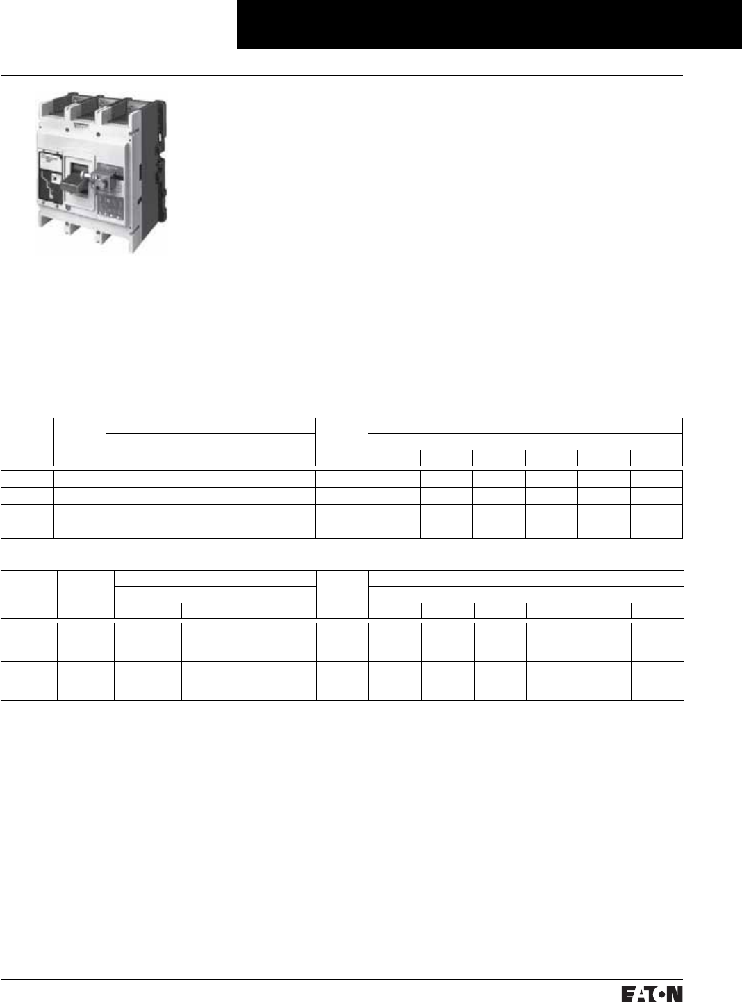
March 1999
PG.74A.01.T.E
Cutler-Hammer 89
Molded Case Circuit Breakers
800-2500 Amperes
Series C R-Frame
Typical Series C R-Frame Circuit Breaker
➀Utilization Category A circuit breakers.
➁See page 90 for Trip Unit Selection Guide
➂100% Rated breakers.
Interrupting Capacity Ratings
UL489/CSA Interrupting Capacity Ratings ➀
Circuit
Breaker
Type
Number of
Poles
Interrupting Capacity (Symmetrical Amperes) (kA) Circuit
Breaker
Type
Page Numbers
Volts Ac (50/60 Hz) Trip Unit Types➁
240 277 480 600 310 510 610 810 910 OPTIM
RD 3, 4 125 – 65 50 RD 91 94 96 98 100 102
CRD ➂ 3, 4 125 – 65 50 CRD 93 95 97 99 101 103
RDC 3, 4 200 – 100 65 RDC 92 94 96 98 100 102
CRDC ➂ 3, 4 200 – 100 65 CRDC 93 95 97 99 101 103
IEC 947-2 Interrupting Capacity Ratings ➀
Circuit
Breaker
Type
Number of
Poles
Interrupting Capacity (Symmetrical Amperes) (kA) Circuit
Breaker
Type
Page Numbers
Volts Ac (50/60 Hz) Trip Unit Types➁
240 415 690 310 510 610 810 910 OPTIM
RD
ICU
ICS
3, 4
135
100
70
50
25
13
RD 91 94 96 98 100 102
RDC
ICU
ICS
3, 4
200
100
100
50
35
18
RDC 92 94 96 98 100 102
■R-frame circuit breakers are avail-
able as frame (which includes trip
unit), rating plug and terminals.
■All R-frame circuit breakers are
suitable for reverse feed use.
PG.74A.01.T.E
Cutler-Hammer
90 March 1999
Molded Case Circuit Breakers
125-600 Amperes
Series C R-Frame
➀Adjust by rating plug.
➁Except 2500 ampere frame is 200-600%.
➂Varies by frame.
➃LS/LSG only.
➄Not to exceed 1200 amperes.
➅By OPTIMizer/BIM.
BIM = Breaker Interface Module
(A) = GF Alarm
Is = Sensor Rating
In = Rating Plug
Ir = Long Delay Pickup Setting x In
R-Frame Digitrip Selection Guide
Trip Unit Type Digitrip
RMS 310
Digitrip
RMS 510
Digitrip
RMS 610
Digitrip
OPTIM 750
Digitrip
RMS 810
Digitrip
RMS 910
Digitrip
OPTIM 1050
RMS Sensing Yes Yes Yes Yes Yes Yes Yes
Breaker Type
Frame R R R R R R R
Ampere Range 800A-2500A 800A-2500A 800A-2500A 800A-2500A 800A-2500A 800A-2500A 800A-2500A
Interrupting Rating @ 480V 65, 100 (kA) 65, 100 (kA) 65, 100 (kA) 65, 100 (kA) 65, 100 (kA) 65, 100 (kA) 65, 100 (kA)
Protection
Ordering Options LS, LSG LSI, LSIG LI, LS, LSI,
LIG, LSG,
LSIG
LI, LS, LSI, LIG
LSG, LSIG
LSI(A), LSIG LI, LS, LSI,
LIG, LSG,
LSIG
LI, LS, LSI,
LIG, LSG,
LSIG
LSI(A), LISG
Fixed Rated Plug (In) Yes Yes Yes Yes Yes Yes Yes Yes
Overtemperature Trip Yes Yes Yes Yes Yes Yes Yes Yes
Long Delay Protection (L)
Adjustable Rating Plug (In) Yes Yes No No No No No No
Long Delay Pickup 0.5-1.0 (In)➀0.5-1.0 (In)➀0.5-1.0 x (In) 0.5-1.0 x (In) 0.4-1.0 x (In) 0.5-1.0 x (In) 0.5-1.0 x (In) 0.4-1.0 x (In)
Long Delay Time I2T 12 Seconds 12 Seconds 2-24 Seconds 2-24 Seconds 2-24 Seconds 2-24 Seconds 2-24 Seconds 2-24 Seconds
Long Delay Time I4T No No No No 1-5 Seconds No No 1-5 Seconds
Long Delay Thermal Memory Yes Yes Yes Yes Yes Yes Yes Yes
High Load Alarm No No No 0.85 x Ir0.5-1.0 x Ir0.85 x Ir0.85 x Ir0.5-1.0 x Ir
Short Delay Protection (S)
Short Delay Pickup 200-800% x (In)➁200-800% x (In)➁200-600%
S1&S2 x (Ir)
200-600%
S1&S2 x (Ir)
150-800% x (Ir)➁➂ 200-600%
S1&S2 x (Ir)
200-600%
S1&S2 x (Ir)
150-800% x (Ir)➁➂
Short Delay Time I2T 100 ms No 100-500 ms 100-500 ms 100-500 ms 100-500 ms 100-500 ms 100-500 ms
Short Delay Time Flat No Inst-300 ms 100-500 ms 100-500 ms 100-500 ms 100-500 ms 100-500 ms 100-500 ms
Short Delay Time Zone
Selective Interlocking
No No Yes Yes Yes Yes Yes Yes
Instantaneous Protection (I)
Instantaneous Pick Up No 200-800% x (In) 200-600%
M1&M2 x (In)
200-600%
M1&M2 x (In)
200-800% x (In)➂200-600%
M1&M2 x (In)
200-600%
M1&M2 x (In)
200-800% x (In)➂
Discriminator No No Yes➃Yes➃Yes Yes➃Yes➃Yes
Instantaneous Override Yes Yes Yes Yes Yes Yes Yes Yes
Ground Fault Protection (G)
Ground Fault Alarm➄No No No No 25-100% x (In) No No 25-100% x (In)
Ground Fault Pick Up➄Varies by Frame Varies by Frame 25-100% x (Is) 25-100% x (Is) 25-100% x (In) 25-100% x (Is) 25-100% x (Is) 25-100% x (In)
Ground Fault Delay I2T No No 100-500 ms 100-500 ms 100-500 ms 100-500 ms 100-500 ms 100-500 ms
Ground Fault Delay Flat Inst-500 ms Inst-500 ms 100-500 ms 100-500 ms 100-500 ms 100-500 ms 100-500 ms 100-500 ms
Ground Fault Zone
Selective Interlocking
No No Yes Yes Yes Yes Yes Yes
Ground Fault Thermal Memory Yes Yes Yes Yes Yes Yes Yes Yes
System Diagnostics
Status LEDs Yes Yes Yes Yes Yes Yes Yes Yes
Cause of Trip LEDs No No Yes Yes Yes Yes Yes Yes
Magnitude of Trip Information No No No Yes Yes Yes Yes Yes
Remote Signal Contacts Yes Yes No Yes Yes Yes Yes Yes
System Monitoring
Digital Display No No No Yes Yes➅Yes Yes Yes➅
Current No No No Yes Yes Yes Yes Yes
Voltage No No No No No No Yes No
Power and Energy No No No No No Yes Yes Yes
Power Quality-Harmonics No No No No No No Yes Yes
Power Factor No No No No No Yes (Over
Cutler-Ham-
mer Power-
Net Only)
Yes Yes
Communications
Cutler-Hammer PowerNet No No No No Yes Yes Yes Yes
Testing
Testing Method Test Set Integral Integral OPTIMizer,
BIM, Cutler-Ham-
mer PowerNet
Integral Integral OPTIMizer,
BIM, Cutler-Ham-
mer PowerNet

March 1999
PG.74A.01.T.E
Cutler-Hammer 91
Molded Case Circuit Breakers
800-2500 Amperes
Series C R-Frame
Digitrip RMS 310 Electronic Circuit Breakers with Interchangeable Rating Plugs
Order as individual components: Breaker Frame (which includes Trip Unit) and Rating Plug.
Maximum
Continuous
Ampere
Rating
@ 40°C
Circuit Breaker Frame Only Digitrip RMS 310 Rating Plug Only
L – Adjustable Long Delay Pickup (By Adjustable Rating Plug)
S – Adjustable Short Delay Pickup with Fixed Short Delay Time
(I2t Response) or Adjustable Short Delay Time (Flat Response)
I – Adjustable Instantaneous Pickup by Setting Short Delay Time to Instantaneous
G – Adjustable Ground Fault Pickup with Adjustable Ground Fault Time (Flat Response)
Ampere
Rating
Fixed
Rating
Plug
Adjustable Rating Plug
Adjustable Ampere Ratings
Catalog Number
LS LSI LSG➂LSIG➂
Catalog Number
3-Pole Standard Interrupting Capacity 600 Volt Ac Rated 65 kAIC @ 480 Vac
1600➀RD316T33W RD316T32W RD316T35W RD316T36W 800
1000
1200
1250
1400
1500
1600
16RES08T
16RES10T
16RES12T
16RES125T
16RES14T
16RES15T
16RES16T
Adjustable Settings are:
800, 1000, 1200, 1600
A16RES16T1
2000 RD320T33W RD320T32W RD320T35W RD320T36W 1000
1200
1250
1400
1600
2000
20RES10T
20RES12T
20RES125T
20RES14T
20RES16T
20RES20T
Adjustable Settings are:
1000, 1200, 1600, 2000
A20RES20T1
2500 RD325T33W RD325T32W RD325T35W RD325T36W 1200
1250
1600
2000
2500
25RES12T
25RES125T
25RES16T
25RES20T
25RES25T
Adjustable Settings are:
1200, 1600, 2000, 2500
A25RES25T1
4-Pole➁ Standard Interrupting Capacity 600 Volt Ac Rated 65 kAIC @ 480 Vac
1600➀RD416T33W RD416T32W – – 800
1000
1200
1250
1400
1500
1600
16RES08T
16RES10T
16RES12T
16RES125T
16RES14T
16RES15T
16RES16T
Adjustable Settings are:
800, 1000, 1200, 1600
A16RES16T1
2000 RD420T33W RD420T32W – – 1000
1200
1250
1400
1600
2000
20RES10T
20RES12T
20RES125T
20RES14T
20RES16T
20RES20T
Adjustable Settings are:
1000, 1200, 1600, 2000
A20RES20T1
2500 RD425T33W RD425T32W – – 1200
1250
1600
2000
2500
25RES12T
25RES125T
25RES16T
25RES20T
25RES25T
Adjustable Settings are:
1200, 1600, 2000, 2500
A25RES25T1
➀For SCR application use 2000 ampere frame.
➁Unprotected right pole neutral. Add “P” to
catalog number for 100% protected right
pole neutral, i.e., “RD416T33PW”.
➂Add suffix “R” to breaker catalog number for
ground fault remote indication
compatibility.
Instruction Leaflet/FRED Number 29C107 for Breaker; Number 29C883 for Digitrip 310 Trip Unit
Time/Current Curves, Dimension Sheets, Application Data

PG.74A.01.T.E
Cutler-Hammer
92 March 1999
Molded Case Circuit Breakers
800-2500 Amperes
Series C L-Frame
Digitrip RMS 310 Electronic Circuit Breakers with Interchangeable Rating Plugs
Order as individual components: Breaker Frame (which includes Trip Unit) and Rating Plug.
Maximum
Continuous
Ampere
Rating
@ 40°C
Circuit Breaker Frame Only Digitrip RMS 310 Rating Plug Only
L – Adjustable Long Delay Pickup (By Adjustable Rating Plug)
S – Adjustable Short Delay Pickup with Fixed Short Delay Time
(I2t Response) or Adjustable Short Delay Time (Flat Response)
I – Adjustable Instantaneous Pickup by Setting Short Delay Time to Instantaneous
G – Adjustable Ground Fault Pickup with Adjustable Ground Fault Time (Flat Response)
Ampere
Rating
Fixed
Rating
Plug
Adjustable Rating Plug
Adjustable Ampere Ratings
Catalog Number
LS LSI LSG➂LSIG➂
Catalog Number
3-Pole High Interrupting Capacity 600 Volt Ac Rated 100 kAIC @ 480 Vac
1600➀RDC316T33W RDC316T32W RDC316T35W RDC316T36W 800
1000
1200
1250
1400
1500
1600
16RES08T
16RES10T
16RES12T
16RES125T
16RES14T
16RES15T
16RES16T
Adjustable Settings are:
800, 1000, 1200, 1600
A16RES16T1
2000 RDC320T33W RDC320T32W RDC320T35W RDC320T36W 1000
1200
1250
1400
1600
2000
20RES10T
20RES12T
20RES125T
20RES14T
20RES16T
20RES20T
Adjustable Settings are:
1000, 1200, 1600, 2000
A20RES20T1
2500 RDC325T33W RDC325T32W RDC325T35W RDC325T36W 1200
1250
1600
2000
2500
25RES12T
25RES125T
25RES16T
25RES20T
25RES25T
Adjustable Settings are:
1200, 1600, 2000, 2500
A25RES25T1
4-Pole➁ High Interrupting Capacity 600 Volt Ac Rated 100 kAIC @ 480 Vac
1600➀RDC416T33W RDC416T32W – – 800
1000
1200
1250
1400
1500
1600
16RES08T
16RES10T
16RES12T
16RES125T
16RES14T
16RES15T
16RES16T
Adjustable Settings are:
800, 1000, 1200, 1600
A16RES16T1
2000 RDC420T33W RDC420T32W – – 1000
1200
1250
1400
1600
2000
20RES10T
20RES12T
20RES125T
20RES14T
20RES16T
20RES20T
Adjustable Settings are:
1000, 1200, 1600, 2000
A20RES20T1
2500 RDC425T33W RDC425T32W – – 1200
1250
1600
2000
2500
25RES12T
25RES125T
25RES16T
25RES20T
25RES25T
Adjustable Settings are:
1200, 1600, 2000, 2500
A25RES25T1
➀For SCR application use 2000 ampere frame.
➁Unprotected right pole neutral. Add “P” to
catalog number for 100% protected right
pole neutral, i.e., “RDC416T33PW”.
➂Add suffix “R” to breaker catalog number for
ground fault remote indication
compatibility.
Instruction Leaflet/FRED Number 29C107 for Breaker; Number 29C883 for Digitrip 310 Trip Unit
Time/Current Curves, Dimension Sheets, Application Data
March 1999
PG.74A.01.T.E
Cutler-Hammer 93
Molded Case Circuit Breakers
800-2500 Amperes
Series C R-Frame
100% Rated Digitrip RMS 310 Electronic Circuit Breakers➀
The NEC allows the breaker to be rated at 100% of its frame size in an assembly, provided that 90°C wire is applied at
75°C ampacity. Order as individual components: Breaker Frame (which includes Trip Unit) and Rating Plug.
Maximum
Continuous
Ampere
Rating
@ 40°C
Circuit Breaker Frame Only Digitrip RMS 310 Rating Plug Only
L – Adjustable Long Delay Pickup (By Adjustable Rating Plug)
S – Adjustable Short Delay Pickup with Fixed Short Delay Time
(I2t Response) or Adjustable Short Delay Time (Flat Response)
I – Adjustable Instantaneous Pickup by Setting Short Delay Time to Instantaneous
G – Adjustable Ground Fault Pickup with Adjustable Ground Fault Time (Flat Response)
Ampere
Rating
Fixed
Rating
Plug
Adjustable Rating Plug
Adjustable Ampere Ratings
Catalog Number
LS LSI LSG➂LSIG➂
Catalog Number
3-Pole Standard Interrupting Capacity 600 Volt Ac Rated 65 kAIC @ 480 Vac
1600➁CRD316T33W CRD316T32W CRD316T35W CRD316T36W 800
1000
1200
1250
1400
1500
1600
16RES08T
16RES10T
16RES12T
16RES125T
16RES14T
16RES15T
16RES16T
Adjustable Settings are:
800, 1000, 1200, 1600
A16RES16T1
2000 CRD320T33W CRD320T32W CRD320T35W CRD320T36W 1000
1200
1250
1400
1600
2000
20RES10T
20RES12T
20RES125T
20RES14T
20RES16T
20RES20T
Adjustable Settings are:
1000, 1200, 1600, 2000
A20RES20T1
3-Pole High Interrupting Capacity 600 Volt Ac Rated 100 kAIC @ 480 Vac
1600➀➁ CRDC316T33W CRDC316T32W CRDC316T35W CRDC316T36W 800
1000
1200
1250
1400
1500
1600
16RES08T
16RES10T
16RES12T
16RES125T
16RES14T
16RES15T
16RES16T
Adjustable Settings are:
800, 1000, 1200, 1600
A16RES16T1
2000 CRDC320T33W CRDC320T32W CRDC320T35W CRDC320T36W 1000
1200
1250
1400
1600
2000
20RES10T
20RES12T
20RES125T
20RES14T
20RES16T
20RES20T
Adjustable Settings are:
1000, 1200, 1600, 2000
A20RES20T1
➀Includes B2016RDL rear connections.
Refer to TD.29.02.T.E for dimensions.
➁For SCR application use 2000 ampere frame.
➂Add suffix “R” to breaker catalog number for
ground fault remote indication
compatibility.
Instruction Leaflet/FRED Number 29C107 for Breaker; Number 29C883 for Digitrip 310 Trip Unit
Time/Current Curves, Dimension Sheets, Application Data

PG.74A.01.T.E
Cutler-Hammer
94 March 1999
Molded Case Circuit Breaker
800-2500 Amperes
Series C R-Frame
Digitrip RMS 510 Electronic Circuit Breakers with Interchangeable Rating Plugs
Order as individual components: Breaker Frame (which includes Trip Unit) and Rating Plug.
Maximum
Continuous
Ampere
Rating
@ 40°C
Circuit Breaker Frame Only Digitrip Rating Plug Only
L – Adjustable Long Delay Pickup (Ir) with Adjustable Long Delay Time
S – Adjustable Short Delay Pickup with Adjustable Short Delay Time (I2t or Flat Response)
I – Adjustable Instantaneous Pickup
G – Adjustable Ground Fault Pickup with Adjustable Ground Fault Time Delay (I2t or Flat Response)
Fixed Rating Plug
Rated
Current (In)
Catalog
Number
LI LS LSI LIG LSG LSIG
Catalog Number
3-Pole Standard Interrupting Capacity 600 Volt Ac Rated 65 kAIC @ 480 Vac
1600 RD316T51W RD316T53W RD316T52W RD316T54W RD316T55W RD316T56W 800
1000
1200
1600
RP6R16A080
RP6R16A100
RP6R16A120
RP6R16A160
2000 RD320T51W RD320T53W RD320T52W RD320T54W RD320T55W RD320T56W 1000
1200
1600
2000
RP6R20A100
RP6R20A120
RP6R20A160
RP6R20A200
2500 RD325T51W RD325T53W RD325T52W RD325T54W RD325T55W RD325T56W 1600
2000
2500
RP6R25A160
RP6R25A200
RP6R25A250
3-Pole High Interrupting Capacity 600 Volt Ac Rated 100 kAIC @ 480 Vac
1600 RDC316T51W RDC316T53W RDC316T52W RDC316T54W RDC316T55W RDC316T56W 800
1000
1200
1600
RP6R16A080
RP6R16A100
RP6R16A120
RP6R16A160
2000 RDC320T51W RDC320T53W RDC320T52W RDC320T54W RDC320T55W RDC320T56W 1000
1200
1600
2000
RP6R20A100
RP6R20A120
RP6R20A160
RP6R20A200
2500 RDC325T51W RDC325T53W RDC325T52W RDC325T54W RDC325T55W RDC325T56W 1600
2000
2500
RP6R25A160
RP6R25A200
RP6R25A250
Instruction Leaflet/FRED Number 29C107 for Breaker; Number 29C885 for Digitrip 510 Trip Unit
Time/Current Curves, Dimension Sheets, Application Data

March 1999
PG.74A.01.T.E
Cutler-Hammer 95
Molded Case Circuit Breakers
800-2500 Amperes
Series C R-Frame
100% Rated Digitrip RMS 510 Circuit Breakers
The NEC allows the breaker to be rated at 100% of its frame size in an assembly, provided that 90°C wire is applied at
75°C ampacity. Order as individual components: Breaker Frame (which includes Trip Unit) and Rating Plug.
Maximum
Continuous
Ampere
Rating
@ 40°C
Circuit Breaker Frame Only Digitrip Rating Plug Only
L – Adjustable Long Delay Pickup (Ir) with Adjustable Long Delay Time
S – Adjustable Short Delay Pickup with Adjustable Short Delay Time (I2t or Flat Response)
I – Adjustable Instantaneous Pickup
G – Adjustable Ground Fault Pickup with Adjustable Ground Fault Time Delay (I2t or Flat Response)
Fixed Rating Plug
Rated
Current (In)
Catalog
Number
LI LS LSI LIG LSG LSIG
Catalog Number
3-Pole Standard Interrupting Capacity 600 Volt Ac Rated 65 kAIC @ 480 Vac
1600 CRD316T51W CRD316T53W CRD316T52W CRD316T54W CRD316T55W CRD316T56W 800
1000
1200
1600
RP6R16A080
RP6R16A100
RP6R16A120
RP6R16A160
2000 CRD320T51W CRD320T53W CRD320T52W CRD320T54W CRD320T55W CRD320T56W 1000
1200
1600
2000
RP6R20A100
RP6R20A120
RP6R20A160
RP6R20A200
3-Pole High Interrupting Capacity 600 Volt Ac Rated 100 kAIC @ 480 Vac
1600 CRDC316T51W CRDC316T53W CRDC316T52W CRDC316T54W CRDC316T55W CRDC316T56W 800
1000
1200
1600
RP6R16A080
RP6R16A100
RP6R16A120
RP6R16A160
2000 CRDC320T51W CRDC320T53W CRDC320T52W CRDC320T54W CRDC320T55W CRDC320T56W 1000
1200
1600
2000
RP6R20A100
RP6R20A120
RP6R20A160
RP6R20A200
Instruction Leaflet/FRED Number 29C107 for Breaker; Number 29885 for Digitrip 510 Trip Unit
Time/Current Curves, Dimension Sheets, Application Data

PG.74A.01.T.E
Cutler-Hammer
96 March 1999
Molded Case Circuit Breakers
800-2500 Amperes
Series C R-Frame
Digitrip RMS 610 Electronic Circuit Breakers with Interchangeable Rating Plugs
Order as individual components: Breaker Frame (which includes Trip Unit) and Rating Plug.
Maximum
Continuous
Ampere
Rating
@ 40°C
Circuit Breaker Frame Only Digitrip Rating Plug Only
L – Adjustable Long Delay Pickup (Ir) with Adjustable Long Delay Time
S – Adjustable Short Delay Pickup with Adjustable Short Delay Time (I2t or Flat Response)
I – Adjustable Instantaneous Pickup
G – Adjustable Ground Fault Pickup with Adjustable Ground Fault Time Delay (I2t or Flat Response)
Fixed Rating Plug
Rated
Current (In)
Catalog
Number
LI LS LSI LIG LSG LSIG
Catalog Number
3-Pole Standard Interrupting Capacity 600 Volt Ac Rated 65 kAIC @ 480 Vac
1600 RD316T61W RD316T63W RD316T62W RD316T64W RD316T65W RD316T66W 800
1000
1200
1600
RP6R16A080
RP6R16A100
RP6R16A120
RP6R16A160
2000 RD320T61W RD320T63W RD320T62W RD320T64W RD320T65W RD320T66W 1000
1200
1600
2000
RP6R20A100
RP6R20A120
RP6R20A160
RP6R20A200
2500 RD325T61W RD325T63W RD325T62W RD325T64W RD325T65W RD325T66W 1600
2000
2500
RP6R25A160
RP6R25A200
RP6R25A250
3-Pole High Interrupting Capacity 600 Volt Ac Rated 100 kAIC @ 480 Vac
1600 RDC316T61W RDC316T63W RDC316T62W RDC316T64W RDC316T65W RDC316T66W 800
1000
1200
1600
RP6R16A080
RP6R16A100
RP6R16A120
RP6R16A160
2000 RDC320T61W RDC320T63W RDC320T62W RDC320T64W RDC320T65W RDC320T66W 1000
1200
1600
2000
RP6R20A100
RP6R20A120
RP6R20A160
RP6R20A200
2500 RDC325T61W RDC325T63W RDC325T62W RDC325T64W RDC325T65W RDC325T66W 1600
2000
2500
RP6R25A160
RP6R25A200
RP6R25A250
Instruction Leaflet/FRED Number 29C107 for Breaker; Number 29886 for Digitrip 610 Trip Unit
Time/Current Curves, Dimension Sheets, Application Data

March 1999
PG.74A.01.T.E
Cutler-Hammer 97
Molded Case Circuit Breakers
800-2500 Amperes
Series C R-Frame
100% Rated Digitrip RMS 610 Circuit Breakers
The NEC allows the breaker to be rated at 100% of its frame size in an assembly, provided that 90°C wire is applied at
75°C ampacity. Order as individual components: Breaker Frame (which includes Trip Unit) and Rating Plug.
Maximum
Continuous
Ampere
Rating
@ 40°C
Circuit Breaker Frame Only Digitrip Rating Plug Only
L – Adjustable Long Delay Pickup (Ir) with Adjustable Long Delay Time
S – Adjustable Short Delay Pickup with Adjustable Short Delay Time (I2t or Flat Response)
I – Adjustable Instantaneous Pickup
G – Adjustable Ground Fault Pickup with Adjustable Ground Fault Time Delay (I2t or Flat Response)
Fixed Rating Plug
Rated
Current (In)
Catalog
Number
LI LS LSI LIG LSG LSIG
Catalog Number
3-Pole Standard Interrupting Capacity 600 Volt Ac Rated 65 kAIC @ 480 Vac
1600 CRD316T61W CRD316T63W CRD316T62W CRD316T64W CRD316T65W CRD316T66W 800
1000
1200
1600
RP6R16A080
RP6R16A100
RP6R16A120
RP6R16A160
2000 CRD320T61W CRD320T63W CRD320T62W CRD320T64W CRD320T65W CRD320T66W 1000
1200
1600
2000
RP6R20A100
RP6R20A120
RP6R20A160
RP6R20A200
3-Pole High Interrupting Capacity 600 Volt Ac Rated 100 kAIC @ 480 Vac
1600 CRDC316T61W CRDC316T63W CRDC316T62W CRDC316T64W CRDC316T65W CRDC316T66W 800
1000
1200
1600
RP6R16A080
RP6R16A100
RP6R16A120
RP6R16A160
2000 CRDC320T61W CRDC320T63W CRDC320T62W CRDC320T64W CRDC320T65W CRDC320T66W 1000
1200
1600
2000
RP6R20A100
RP6R20A120
RP6R20A160
RP6R20A200
Instruction Leaflet/FRED Number 29C107 for Breaker; Number 29886 for Digitrip 610 Trip Unit
Time/Current Curves, Dimension Sheets, Application Data

PG.74A.01.T.E
Cutler-Hammer
98 March 1999
Molded Case Circuit Breakers
800-2500 Amperes
Series C R-Frame
Digitrip RMS 810 Electronic Circuit Breakers with Interchangeable Rating Plugs
Order as individual components: Breaker Frame (which includes Trip Unit) and Rating Plug.
Maximum
Continuous
Ampere
Rating
@ 40°C
Circuit Breaker Frame Only Digitrip Rating Plug Only
L – Adjustable Long Delay Pickup (Ir) with Adjustable Long Delay Time
S – Adjustable Short Delay Pickup with Adjustable Short Delay Time (I2t or Flat Response)
I – Adjustable Instantaneous Pickup
G – Adjustable Ground Fault Pickup with Adjustable Ground Fault Time Delay (I2t or Flat Response)
Fixed Rating Plug
Rated
Current (In)
Catalog
Number
LI LS LSI LIG LSG LSIG
Catalog Number
3-Pole Standard Interrupting Capacity 600 Volt Ac Rated 65 kAIC @ 480 Vac
1600 RD316T81W RD316T83W RD316T82W RD316T84W RD316T85W RD316T86W 800
1000
1200
1600
RP6R16A080
RP6R16A100
RP6R16A120
RP6R16A160
2000 RD320T81W RD320T83W RD320T82W RD320T84W RD320T85W RD320T86W 1000
1200
1600
2000
RP6R20A100
RP6R20A120
RP6R20A160
RP6R20A200
2500 RD325T81W RD325T83W RD325T82W RD325T84W RD325T85W RD325T86W 1600
2000
2500
RP6R25A160
RP6R25A200
RP6R25A250
3-Pole High Interrupting Capacity 600 Volt Ac Rated 100 kAIC @ 480 Vac
1600 RDC316T81W RDC316T83W RDC316T82W RDC316T84W RDC316T85W RDC316T86W 800
1000
1200
1600
RP6R16A080
RP6R16A100
RP6R16A120
RP6R16A160
2000 RDC320T81W RDC320T83W RDC320T82W RDC320T84W RDC320T85W RDC320T86W 1000
1200
1600
2000
RP6R20A100
RP6R20A120
RP6R20A160
RP6R20A200
2500 RDC325T81W RDC325T83W RDC325T82W RDC325T84W RDC325T85W RDC325T86W 1600
2000
2500
RP6R25A160
RP6R25A200
RP6R25A250
Instruction Leaflet/FRED Number 29C107 for Breaker; Number 29888 for Digitrip 810 Trip Unit
Time/Current Curves, Dimension Sheets, Application Data

March 1999
PG.74A.01.T.E
Cutler-Hammer 99
Molded Case Circuit Breakers
800-2500 Amperes
Series C R-Frame
100% Rated Digitrip RMS 810 Circuit Breakers
The NEC allows the breaker to be rated at 100% of its frame size in an assembly, provided that 90°C wire is applied at
75°C ampacity. Order as individual components: Breaker Frame (which includes Trip Unit) and Rating Plug.
Maximum
Continuous
Ampere
Rating
@ 40°C
Circuit Breaker Frame Only Digitrip Rating Plug Only
L – Adjustable Long Delay Pickup (Ir) with Adjustable Long Delay Time
S – Adjustable Short Delay Pickup with Adjustable Short Delay Time (I2t or Flat Response)
I – Adjustable Instantaneous Pickup
G – Adjustable Ground Fault Pickup with Adjustable Ground Fault Time Delay (I2t or Flat Response)
Fixed Rating Plug
Rated
Current (In)
Catalog
Number
LI LS LSI LIG LSG LSIG
Catalog Number
3-Pole Standard Interrupting Capacity 600 Volt Ac Rated 65 kAIC @ 480 Vac
1600 CRD316T81W CRD316T83W CRD316T82W CRD316T84W CRD316T85W CRD316T86W 800
1000
1200
1600
RP6R16A080
RP6R16A100
RP6R16A120
RP6R16A160
2000 CRD320T81W CRD320T83W CRD320T82W CRD320T84W CRD320T85W CRD320T86W 1000
1200
1600
2000
RP6R20A100
RP6R20A120
RP6R20A160
RP6R20A200
3-Pole High Interrupting Capacity 600 Volt Ac Rated 100 kAIC @ 480 Vac
1600 CRDC316T81W CRDC316T83W CRDC316T82W CRDC316T84W CRDC316T85W CRDC316T86W 800
1000
1200
1600
RP6R16A080
RP6R16A100
RP6R16A120
RP6R16A160
2000 CRDC320T81W CRDC320T83W CRDC320T82W CRDC320T84W CRDC320T85W CRDC320T86W 1000
1200
1600
2000
RP6R20A100
RP6R20A120
RP6R20A160
RP6R20A200
Instruction Leaflet/FRED Number 29C107 for Breaker; Number 29888 for Digitrip 810 Trip Unit
Time/Current Curves, Dimension Sheets, Application Data
PG.74A.01.T.E
Cutler-Hammer
100 March 1999
Molded Case Circuit Breakers
800-2500 Amperes
Series C R-Frame
Digitrip RMS 910 Electronic Circuit Breakers with Interchangeable Rating Plugs
Order as individual components: Breaker Frame (which includes Trip Unit) and Rating Plug.
Maximum
Continuous
Ampere
Rating
@ 40°C
Circuit Breaker Frame Only Digitrip Rating Plug Only
L – Adjustable Long Delay Pickup (Ir) with Adjustable Long Delay Time
S – Adjustable Short Delay Pickup with Adjustable Short Delay Time (I2t or Flat Response)
I – Adjustable Instantaneous Pickup
G – Adjustable Ground Fault Pickup with Adjustable Ground Fault Time Delay (I2t or Flat Response)
Fixed Rating Plug
Rated
Current (In)
Catalog
Number
LI LS LSI LIG LSG LSIG
Catalog Number
3-Pole Standard Interrupting Capacity 600 Volt Ac Rated 65 kAIC @ 480 Vac
1600 RD316T91W RD316T93W RD316T92W RD316T94W RD316T95W RD316T96W 800
1000
1200
1600
RP6R16A080
RP6R16A100
RP6R16A120
RP6R16A160
2000 RD320T91W RD320T93W RD320T92W RD320T94W RD320T95W RD320T96W 1000
1200
1600
2000
RP6R20A100
RP6R20A120
RP6R20A160
RP6R20A200
2500 RD325T91W RD325T93W RD325T92W RD325T94W RD325T95W RD325T96W 1600
2000
2500
RP6R25A160
RP6R25A200
RP6R25A250
3-Pole High Interrupting Capacity 600 Volt Ac Rated 100 kAIC @ 480 Vac
1600 RDC316T91W RDC316T93W RDC316T92W RDC316T94W RDC316T95W RDC316T96W 800
1000
1200
1600
RP6R16A080
RP6R16A100
RP6R16A120
RP6R16A160
2000 RDC320T91W RDC320T93W RDC320T92W RDC320T94W RDC320T95W RDC320T96W 1000
1200
1600
2000
RP6R20A100
RP6R20A120
RP6R20A160
RP6R20A200
2500 RDC325T91W RDC325T93W RDC325T92W RDC325T94W RDC325T95W RDC325T96W 1600
2000
2500
RP6R25A160
RP6R25A200
RP6R25A250
Instruction Leaflet/FRED Number 29C107 for Breaker; Number 29889 for Digitrip 910 Trip Unit
Time/Current Curves, Dimension Sheets, Application Data

March 1999
PG.74A.01.T.E
Cutler-Hammer 101
Molded Case Circuit Breakers
800-2500 Amperes
Series C R-Frame
100% Rated Digitrip RMS 910 Circuit Breakers
The NEC allows the breaker to be rated at 100% of its frame size in an assembly, provided that 90°C wire is applied at
75°C ampacity. Order as individual components: Breaker Frame (which includes Trip Unit) and Rating Plug.
Maximum
Continuous
Ampere
Rating
@ 40°C
Circuit Breaker Frame Only Digitrip Rating Plug Only
L – Adjustable Long Delay Pickup (Ir) with Adjustable Long Delay Time
S – Adjustable Short Delay Pickup with Adjustable Short Delay Time (I2t or Flat Response)
I – Adjustable Instantaneous Pickup
G – Adjustable Ground Fault Pickup with Adjustable Ground Fault Time Delay (I2t or Flat Response)
Fixed Rating Plug
Rated
Current (In)
Catalog
Number
LI LS LSI LIG LSG LSIG
Catalog Number
3-Pole Standard Interrupting Capacity 600 Volt Ac Rated 65 kAIC @ 480 Vac
1600 CRD316T91W CRD316T93W CRD316T92W CRD316T94W CRD316T95W CRD316T96W 800
1000
1200
1600
RP6R16A080
RP6R16A100
RP6R16A120
RP6R16A160
2000 CRD320T91W CRD320T93W CRD320T92W CRD320T94W CRD320T95W CRD320T96W 1000
1200
1600
2000
RP6R20A100
RP6R20A120
RP6R20A160
RP6R20A200
3-Pole High Interrupting Capacity 600 Volt Ac Rated 100 kAIC @ 480 Vac
1600 CRDC316T91W CRDC316T93W CRDC316T92W CRDC316T94W CRDC316T95W CRDC316T96W 800
1000
1200
1600
RP6R16A080
RP6R16A100
RP6R16A120
RP6R16A160
2000 CRDC320T91W CRDC320T93W CRDC320T92W CRDC320T94W CRDC320T95W CRDC320T96W 1000
1200
1600
2000
RP6R20A100
RP6R20A120
RP6R20A160
RP6R20A200
Instruction Leaflet/FRED Number 29C107 for Breaker; Number 29889 for Digitrip 910 Trip Unit
Time/Current Curves, Dimension Sheets, Application Data

PG.74A.01.T.E
Cutler-Hammer
102 March 1999
Molded Case Circuit Breakers
800-2500 Amperes
Series C R-Frame
Digitrip OPTIM Electronic Circuit Breakers with Interchangeable Rating Plugs
Order as individual components: Breaker Frame (which includes Trip Unit) and Rating Plug.
Maximum
Continuous
Ampere
Rating
@ 40°C
Circuit Breaker Frame Only Digitrip OPTIM Rating Plug Only
L – Adjustable Long Delay Pickup (Ir) with Adjustable Long Delay Time
S – Adjustable Short Delay Pickup with Adjustable Short Delay Time (I2t or Flat Response)
I – Adjustable Instantaneous Pickup
G – Adjustable Ground Fault Pickup with Adjustable Ground Fault Time Delay (I2t or Flat Response)
A – Adjustable Ground Fault Alarm with Adjustable Ground Fault Time Delay (I2t or Flat Response)
Fixed Rating Plug
Ampere
Rating
Catalog
Number
LSIA 750 LSIG 750 LSIA 1050 LSIG 1050
Catalog Number
3-Pole Standard Interrupting Capacity 600 Volt Ac Rated 65 kAIC @ 480 Vac
1600 RD316T77W RD316T76W RD316T107W RD316T106W 800
1000
1200
1600
ORPR16A080
ORPR16A100
0RPR16A120
0RPR16A160
2000 RD320T77W RD320T76W RD320T107W RD320T106W 1000
1200
1600
2000
0RPR20A100
0RPR20A120
0RPR20A160
0RPR20A200
2500 RD325T77W RD325T76W RD325T107W RD325T106W 1600
2000
2500
0RPR25A160
0RPR25A200
0RPR25A250
3-Pole High Interrupting Capacity 600 Volt Ac Rated 100 kAIC @ 480 Vac
1600 RDC316T77W RDC316T76W RDC316T107W RDC316T106W 800
1000
1200
1600
ORPR16A080
ORPR16A100
0RPR16A120
0RPR16A160
2000 RDC320T77W RDC320T76W RDC320T107W RDC320T106W 1000
1200
1600
2000
0RPR20A100
0RPR20A120
0RPR20A160
0RPR20A200
2500 RDC325T77W RDC325T76W RDC325T107W RDC325T106W 1600
2000
2500
0RPR25A160
0RPR25A200
0RPR25A250
Instruction Leaflet/FRED Number 29C107 for Breaker; Number 29C891 for OPTIM Trip Unit
Time/Current Curves, Dimension Sheets, Application Data

March 1999
PG.74A.01.T.E
Cutler-Hammer 103
Molded Case Circuit Breakers
800-2500 Amperes
Series C R-Frame
100% Rated 600 Volt AC Digitrip OPTIM Circuit Breakers with Interchangeable Rating Plugs
Order as individual components: Breaker Frame (which includes Trip Unit) and Rating Plug.
Maximum
Continuous
Ampere
Rating
@ 40°C
Circuit Breaker Frame Only Digitrip OPTIM Rating Plug Only
L – Adjustable Long Delay Pickup (Ir) with Adjustable Long Delay Time
S – Adjustable Short Delay Pickup with Adjustable Short Delay Time (I2t or Flat Response)
I – Adjustable Instantaneous Pickup
G – Adjustable Ground Fault Pickup with Adjustable Ground Fault Time Delay (I2t or Flat Response)
A – Adjustable Ground Fault Alarm with Adjustable Ground Fault Time Delay (I2t or Flat Response)
Fixed Rating Plug
Ampere
Rating
Catalog
Number
LSIA 750 LSIG 750 LSIA 1050 LSIG 1050
3-Pole Standard Interrupting Capacity 600 Volt Ac Rated 65 kAIC @ 480 Vac
1600 CRD316T77W CRD316T76W CRD316T107W CRD316T106W 800
1000
1200
1600
ORPR16A080
ORPR16A100
0RPR16A120
0RPR16A160
2000 CRD320T77W CRD320T76W CRD320T107W CRD320T106W 1000
1200
1600
2000
0RPR20A100
0RPR20A120
0RPR20A160
0RPR20A200
3-Pole High Interrupting Capacity 600 Volt Ac Rated 100 kAIC @ 480 Vac
1600 CRDC316T77W CRDC316T76W CRDC316T107W CRDC316T106W 800
1000
1200
1600
ORPR16A080
ORPR16A100
0RPR16A120
0RPR16A160
2000 CRDC320T77W CRDC320T76W CRDC320T107W CRDC320T106W 1000
1200
1600
2000
0RPR20A100
0RPR20A120
0RPR20A160
0RPR20A200
Instruction Leaflet/FRED Number 29C107 for Breaker; Number 29C891 for OPTIM Trip Unit
Time/Current Curves, Dimension Sheets, Application Data
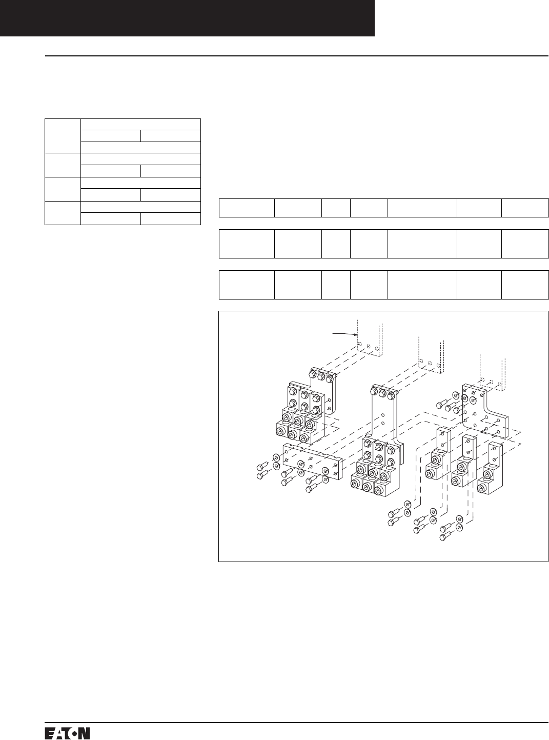
PG.74A.01.T.E
Cutler-Hammer
104 March 1999
Molded Case Circuit Breakers
800-2500 Amperes
Series C R-Frame
Breaker Line/Load
Conductors
➀Catalog number includes bus connection,
terminals, and hardware for either line side
or load side of 3-pole breaker.
Line and Load Terminals
Line and load terminals provide wire
connecting capabilities for specific
ranges of continuous current rat-
ings and wire types. All terminals
comply with Underwriters Labora-
tories, Inc. Standards UL486A and
UL486B and CSA C22.2 No. 65M.
Unless otherwise specified, R-frame
Line and Load Terminals
Maximum
Breaker Amperes
Terminal
Body Material
Wire
Type
Hardware AWG/kcmil Wire
Range/No. Conductors
Metric Wire
Range mm2Catalog
Number
Wire Terminals
1600
1600
2000
Aluminum
Copper
Aluminum
Cu/AI
Cu
Cu/AI
English
English
English
500-1000 (4)
1-600 (4)
2-600 (6)
300-500
50-300
35-300
TA1600RD
T1600RD
TA2000RD➀
Rear Connectors
2000
2000
2500
Copper
Copper
Copper
–
–
–
English
English
English
–
–
–
–
–
–
B2016RD
B2016RDL➁
B2500RD➂
TA2000RD
➁For use with 100% rated 1600A and 2000A
frame. Do not order separately unless for re-
placement purposes. Is included in breaker
carton when 100% rated device is ordered.
➂For use with 2500-amp frame. Do not order
separately unless for replacement purposes.
Included in breaker carton when 2500A
breaker is ordered.
Note: Molded case switch may trip
above 17500 amperes.
Instruction Leaflet/FRED Number 29C106 for
Molded Case Switch
Molded Case Switches
For UL listed, series tested molded
case switch application data, refer to
Cutler-Hammer.
Continuous
Ampere
Rating
@ 40°C
Complete without Terminals
3-Pole 4-Pole
Catalog Number
1600 Type RD – HIgh Instantaneous (K)
RD316WK RD416WK
2000 Type RD – HIgh Instantaneous (K)
RD320WK RD420WK
2500 Type RD – HIgh Instantaneous (K)
––
circuit breaker line load terminals
are shipped separately for field
installation.
Ordering Information
R-frame circuit breakers have Cu/AI
terminals as standard and Cu only
terminals as an option. Specify if
factory installation is required.
March 1999
PG.74A.01.T.E
Cutler-Hammer 105
Molded Case Circuit Breakers
800-2500 Amperes
Series C R-Frame
Circuit Breaker/
Frame Ampere
Rating
16: 1600A
20: 2000A
25: 2500A
➀For complete list of available trip types refer
to pages 91 through 103.
Catalog Numbering System
This information is presented only as an aid to understanding catalog numbers. It is not to be used to build catalog
numbers for circuit breakers or trip units.
Circuit Breaker/Frame Catalog Number
RD 3 16 T32 W
Circuit
Breaker/
Frame Type
RD
RDC
CRD
CRDC
Number
of Poles
3: 3 Poles
4: 4 Poles
Suffix
W: Without
Terminals
P: 100% Protected
Neutral Pole
R: Ground Fault
Remote (310 Only)
K: Molded Case
Switch
Trip Type➀
T32: Digitrip RMS
310 LSI
T53: Digitrip RMS
510 LS
T65: Digitrip RMS
610 LSG
T86: Digitrip RMS
810 LSIG
T96: Digitrip RMS
910 LSIG
T77: Digitrip OPTIM
750 LSIA
T106: Digitrip OPTIM
1050 LSIG
Dimensions/Weights
Dimensions, Inches (mm)
Number of Poles Width Height Depth
3 15.5
(394)
16
(406)
9.75
(248)
4 20
(508)
16
(406)
9.75
(248)
Approximate Shipping Weight, Lbs. (kg)
Breaker
Type
Complete Breaker
Number of Poles
34
1600A
RD, CRD, RDC, CRDC 102
(46.266)
135
(61.235)
2000A
RD, RDC 102
(46.266)
135
(61.235)
CRD, CRDC 130
(58.967)
175
(79.378)
2500A
RD, RDC 135
(61.235)
182
(82.553)
PG.74A.01.T.E
Cutler-Hammer
106 March 1999
Molded Case Circuit Breakers
800-2500 Amperes
Series C R-Frame
Allowable Accessory Combinations
Different combinations of accessories can be supplied, depending on the types of accessories and the number of poles
in the circuit breaker.
Reference
Page
3-Pole 4-Pole
Left Center Right Left Center Right Neu.
Internal Accessories
Alarm Lockout (Make/Break) 141 ■■
Alarm Lockout (2Make/2Break) 141 ■■
Auxiliary Switch (2A, 2B) 144 ■■
Auxiliary Switch (4A, 4B) 144 ■■
Shunt Trip – Standard 151 ■■
Shunt Trip – Low Energy 152 ■■
Undervoltage Release Mechanism 159 ■■
Accessory Terminal Block➁ 160 ■■
External Accessories
Base Mounting Hardware 163
Padlockable Handle Lock Hasp 169 ●●
Key Interlock Kit 170 ■■
Walking Beam Interlock 171
Electrical (Motor) Operator 173 ■■
Drawout Cassette 164 ●
Handle Mechanisms 178 ■■
Handle Extension➀ 182 ■■
Solid-State (Electronic) Portable Test Kit (310 Only) 184 ●●
OPTIM System Components
Breaker Interface Module (BIM) 185 ●
Digitrip OPTIMizer 185 ●
Auxiliary Power Module 185 ●
Cutler-Hammer PowerNet Software 185 ●
Modifications (Refer to Cutler-Hammer)
Special Calibration 186 ●●
Moisture Fungus Treatment 186 ●●
Freeze-Tested Circuit Breakers 186 ●●
Marine Application 186 ●●
➀Included with breaker.
➁Mounts outside breaker.
■Applicable in indicated pole position ●Accessory available/Modification available
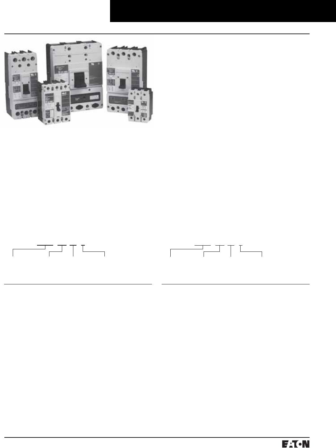
March 1999
PG.74A.01.T.E
Cutler-Hammer 107
Molded Case Circuit Breakers
Series C Motor Circuit Protectors
General Information
Designated as the Cutler-Hammer Types GMCP, HMCP, the
Series C instantaneous-only motor circuit protector (MCP)
is available in ratings from 3A to 600A for motor starter
sizes 0 through 6. The MCP is designed to comply with
the applicable requirements of Underwriters Laboratories,
Inc. Standard UL489, Canadian Standards Association
Standard C22.2 No. 5, and International Electrotechnical
Commission Recommendations IEC 157-1.
An innovative design of internal components allows higher
MCP-starter combination interrupting ratings. The MCP is
marked to permit proper electrical application within the
assigned equipment ratings.
The MCP is a recognized component (UL File E7819) and
complies with the applicable requirements of Underwriters
Laboratories, Inc. Standard UL489. It is also designed to
comply with the applicable requirements of Canadian
Standards Association Standard C22.2 No. 5, Interna-
tional Electrotechnical Commission Recommendations
IEC 157-1, and nameplates bear the CE marking.
Series C Motor Circuit Protectors
Catalog Numbering System
This information is presented only as an aid to under-
standing catalog numbers. It is not to be used to build
catalog numbers for circuit breakers or trip units.
Motor Circuit Protector Catalog Number
HMCP 003 A0 C
Motor
Circuit
Protective
Type
HMCP: 3 Poles
HM2P: 2 Poles➀
HMCPS: 3 Poles
Contin-
uous
Ampere
Rating
003
007
015
025
030
050
070
100
150
250
400
600
Magnetic Trip
Range/NEMA
Starter Size
A0: 9-30/0
C0: 21-70/0
E0: 45-150/0
D0: 40-60/0
H1: 90-300/1
G2: 80-120/2
K2: 150-500/2
J2: 115-170/2
M2: 210-700/2
L3: 160-240/3
R3: 300-1000/3
T4: 450-1500/4
U4: 750-2500/4
A5: 350-700/5
C5: 450-900/5
D5: 500-1000/5
F5: 625-1250/5
G5: 750-1500/5
J5: 875-1750/5
K5: 1000-2000/5
L5: 1125-2250/5
W5: 1250-2500/5
N5: 1500-3000/5
R5: 1750-3500/5
X5: 2000-4000/5
L6: 1800-6000/6 Electronic)
Suffix
C: Non-Aluminum
Terminals
W: W/O Terminals
X: Load Terminals Only
Y: Line Terminals Only
S: Stainless Steel Termi-
nals (150A Frame Only)
No Suffix: Standard
Terminals on Line
and Load
GMCP 003 A0 C
Motor
Circuit
Protective
Device
GMCP: 3 Poles
Contin-
uous
Ampere
Rating
003
007
015
030
050
060
063
Magnetic Trip
Range/NEMA
Starter Size
A0: 15-30/0
C0: 35-70/0
E0: 75-150/0
H1: 150-300/1
K2: 250-500/2
J2: 300-600/2
M2: 320-630/2
Suffix
C: Non-Aluminum
Terminals
➀On J- and K-Frame HMCPs only.
PG.74A.01.T.E
Cutler-Hammer
108 March 1999
Modifications for GMCP
Internal Accessories
These modifications must be factory installed➀.
Note: No UVR available on GMCP.
Type
Accessory
Electrical Ratings Contact
Arrangement
Style
Number
Factory
Suffix
Volts Frequency Amperes
Shunt Trip➂
Shunt Trip➂
120
240
50/60 Hz
50/60 Hz
1.1
2.1
1373D62G18
1373D62G19
S5
S6
Auxiliary Switch➃
Auxiliary Switch➃
240
240
50/60 Hz
50/60 Hz
6.0
6.0
1a/1b
2a/2b
1288C74G03
1288C73G03
A3
A6
Alarm Switch➃240 50/60 Hz 6.0 Make/Break
1288C75G03
B3
Alarm Switch➃
Alarm Switch
Combination
240 50/60 Hz 6.0 1a/1b
Make/Break
1288C76G09
B13
Molded Case Circuit Breakers
Series C Motor Circuit Protectors
G-Frame
480 Vac Maximum, 250 Vdc Maximum
Instruction Leaflet/FRED Number 15579
MCP
Catalog Number
NEMA
Starter Size
Continuous
Amperes
Cam
Setting
Motor Full Load
Center Amperes➄
MCP Trip
Setting
GMCP003A0C 03
A
B
C
D
E
F
1.1 - 1.2
1.3 - 1.5
1.6 - 1.7
1.8 - 1.9
2.0 - 2.2
2.3 - 2.5
15
18
21
24
27
30
GMCP007C0C 07
A
B
C
D
E
F
2.6 - 3.1
3.2 - 3.6
3.7 - 3.9
4.3 - 4.7
4.8 - 5.2
5.3 - 5.7
35
42
49
56
63
70
GMCP015E0C 015
A
B
C
D
E
F
5.7 - 6.8
6.9 - 7.9
8.0 - 9.1
9.2 - 10.3
10.4 - 11.4
11.5 - 12.6
75
90
105
120
135
150
GMCP030H1C 130
A
B
C
D
E
F
11.5 - 13.7
13.8 - 16.0
16.1 - 18.3
18.4 - 20.6
20.7 - 22.9
23.0 - 25.2
150
180
210
240
270
300
GMCP050K2C 250
A
B
C
D
E
F
19.3 - 22.9
23.0 - 26.8
26.9 - 30.6
30.7 - 34.5
34.6 - 38.3
38.4 - 42.1
250
300
350
400
450
500
GMCP060J2C 360
A
B
C
D
E
F
23.1 - 27.5
27.7 - 32.2
32.3 - 36.7
36.9 - 41.4
41.5 - 46.0
46.2 - 50.5
300
360
420
480
540
600
GMCP063M2C 363
A
B
C
D
E
F
24.2 - 32.1
29.1 - 34.8
33.9 - 39.4
38.8 - 46.4
43.6 - 48.9
48.5 - 53.7
320
380
440
500
570
630
➀Only one accessory may be installed in
GMCP.
➁For use with standard 35 mm DIN rail such
as, 35 x 7.5 or 15 mm per DIN EN50022.
➂LH only.
➃RH only.
➄Motor FLA ranges are typical. The corre-
sponding trip setting is at 13 times the mini-
mum FLA value shown. Where a 13 times
setting is required for an intermediate FLA
value, alternate cam settings and/or MCP
ratings should be used.
➅For use with GMCP only.
Instruction Leaflet/FRED Number 15552 for Alarm Switch
Instruction Leaflet/FRED Number 15551 for Auxiliary Switch
Instruction Leaflet/FRED Number 15550 for Shunt Trip
External Mounted Accessories
Description Number Units
in Package
Style Number
Lock Dog (Non-Padlockable)
Mounting Hardware
DIN Rail Adapter➁
1
1
10
1294C01H01
624B375G23
1225C79G02
Instruction Leaflet/FRED Number 29C191 (DIN Rail Adapter)
Vari-Depth Handle Mechanism➅
Description Catalog Number
For Type 1 use
For Type 3R, 4X, 12 use
Close Coupled Black with Gray Handle
Close Coupled Red with Yellow Handle
HRGMV11L
HRGMV14L
HRGMC10
HRGMC30
Time/Current Curves, Dimension Sheets, Application Data

March 1999
PG.74A.01.T.E
Cutler-Hammer 109
Molded Case Circuit Breakers
Series C Motor Circuit Protectors
F-Frame
600 Vac Maximum, 250 Vdc Maximum
MCP
Catalog Number
NEMA
Starter Size
Continuous
Amperes
Cam
Setting
Motor Full Load
Center Amperes➀
MCP Trip
Setting
➁
HMCP003A0C 03
A
B
C
D
E
F
G
H
.69 - .91
.92 - 1.0
1.1 - 1.2
1.3 - 1.5
1.6 - 1.7
1.8 - 1.9
2.0 - 2.2
2.3 - 2.5
9
12
15
18
21
24
27
30
HMCP007C0C 07
A
B
C
D
E
F
G
H
1.5 - 2.0
2.1 - 2.5
2.6 - 3.1
3.2 - 3.6
3.7 - 3.9
4.3 - 4.7
4.8 - 5.2
5.3 - 5.7
21
28
35
42
49
56
63
70
HMCP015E0C 015
A
B
C
D
E
F
G
H
3.4 - 4.5
4.6 - 5.6
5.7 - 6.8
6.9 - 7.9
8.0 - 9.1
9.2 - 10.3
10.4 - 11.4
11.5 - 12.6
45
60
75
90
105
120
135
150
HMCP030H1C 130
A
B
C
D
E
F
G
H
6.9 - 9.1
9.2 - 11.4
11.5 - 13.7
13.8 - 16.0
16.1 - 18.3
18.4 - 20.6
20.7 - 22.9
23.0 - 25.2
90
120
150
180
210
240
270
300
HMCP050K2C 250
A
B
C
D
E
F
G
H
11.5 - 15.2
15.3 - 19.1
19.2 - 22.9
23.0 - 26.8
26.9 - 30.6
30.7 - 34.5
34.6 - 38.3
38.4 - 42.1
150
200
250
300
350
400
450
500
HMCP070M2C 270
A
B
C
D
E
F
G
H
16.1 - 21.4
21.5 - 26.8
26.9 - 32.2
32.3 - 37.5
37.6 - 42.9
43.0 - 48.3
48.4 - 53.7
53.8 - 59.1
210
280
350
420
490
560
630
700
HMCP100R3C 3 100
A
B
C
D
E
F
G
H
23.0 - 30.6
30.7 - 38.3
38.4 - 46.0
46.1 - 53.7
53.8 - 61.4
61.5 - 69.1
69.2 - 76.8
76.9 - 84.5
300
400
500
600
700
800
900
1000
F-Frame
(Continued)
600 Vac Maximum, 250 Vdc Maximum
Instruction Leaflet/FRED Number 29C401
➀Motor FLA ranges are typical. The corresponding trip setting is at
13 times the minimum FLA value shown. Where a 13 times setting is
required for an intermediate FLA value, alternate cam settings and/or
MCP ratings should be used.
➁For Dc applications, actual trip levels are approximately 40% higher
than values shown.
➂Settings above 130 amperes are for special applications. NEC Article
430-110(a) requires the ampere rating of the disconnecting means to be
not less than 115% of the motor full load ampere rating.
MCP
Catalog Number
NEMA
Starter Size
Continuous
Amperes
Cam
Setting
Motor Full Load
Center Amperes➀
MCP Trip
Setting
➁
HMCP150T4C 4 150
A
B
C
D
E
F
G
H
34.6 - 46.0
46.1 - 57.5
57.6 - 69.1
69.2 - 80.6
80.7 - 92.2
92.3 -103.7
103.8 -115.2
115.3 -126.7
450
600
750
900
1050
1200
1350
1500
HMCP150U4C 4 150
A
B
C
D
E
F
G
H
57.0 - 75.0
76.0 - 95.0
96.0 -114.0
115.0 -130.7
➂
➂
➂
➂
750
1000
1250
1500
1750
2000
2250
2500
Special Low Magnetic Protection Application MCP
600 Vac Maximum, 250 Vdc Maximum
MCP
Catalog Number
NEMA
Starter Size
Continuous
Amperes
Cam
Setting
Motor Full Load
Center Amperes
MCP Trip
Setting
➁
HMCPO25D0C
–
–
–
–
–
–
–
–
25A
A
B
C
D
E
F
G
H
–
–
–
–
–
–
–
–
40
43
46
49
52
55
58
60
HMCP050G2C
–
–
–
–
–
–
–
–
50A
A
B
C
D
E
F
G
H
–
–
–
–
–
–
–
–
80
87
93
98
103
109
115
120
HMCP070J2C
–
–
–
–
–
–
–
–
70A
A
B
C
D
E
F
G
H
–
–
–
–
–
–
–
–
115
122
130
139
145
153
160
170
HMCP100L3C
–
–
–
–
–
–
–
–
100A
A
B
C
D
E
F
G
H
–
–
–
–
–
–
–
–
160
174
185
196
207
218
229
240
Instruction Leaflet/FRED Number 29C407
Time/Current Curves, Dimension Sheets, Application Data
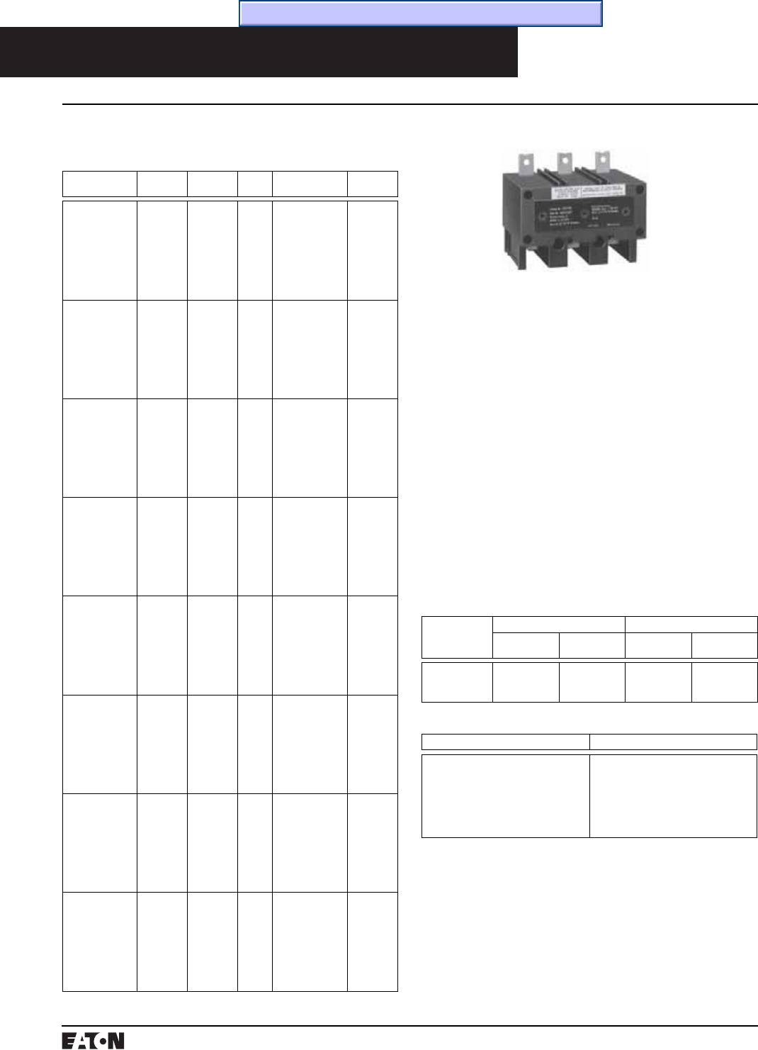
PG.74A.01.T.E
Cutler-Hammer
110 March 1999
MCP
Catalog Number
NEMA
Starter Size
Continuous
Amperes
Cam
Setting
Motor Full Load
Center Amperes➀
MCP Trip
Setting
➁
HMCPS003A0C 03
A
B
C
D
E
F
G
H
.69 - .91
.92 - 1.0
1.1 - 1.2
1.3 - 1.5
1.6 - 1.7
1.8 - 1.9
2.0 - 2.2
2.3 - 2.5
9
12
15
18
21
24
27
30
HMCPS007C0C 07
A
B
C
D
E
F
G
H
1.5 - 2.0
2.1 - 2.5
2.6 - 3.1
3.2 - 3.6
3.7 - 3.9
4.3 - 4.7
4.8 - 5.2
5.3 - 5.7
21
28
35
42
49
56
63
70
HMCPS015E0C 015
A
B
C
D
E
F
G
H
3.4 - 4.5
4.6 - 5.6
5.7 - 6.8
6.9 - 7.9
8.0 - 9.1
9.2 - 10.3
10.4 - 11.4
11.5 - 12.6
45
60
75
90
105
120
135
150
HMCPS030H1C 130
A
B
C
D
E
F
G
H
6.9 - 9.1
9.2 - 11.4
11.5 - 13.7
13.8 - 16.0
16.1 - 18.3
18.4 - 20.6
20.7 - 22.9
23.0 - 25.2
90
120
150
180
210
240
270
300
HMCPS050K2C 250
A
B
C
D
E
F
G
H
11.5 - 15.2
15.3 - 19.1
19.2 - 22.9
23.0 - 26.8
26.9 - 30.6
30.7 - 34.5
34.6 - 38.3
38.4 - 42.1
150
200
250
300
350
400
450
500
HMCPS100R3C 3 100
A
B
C
D
E
F
G
H
23.0 - 30.6
30.7 - 38.3
38.4 - 46.0
46.1 - 53.7
53.8 - 61.4
61.5 - 69.1
69.2 - 76.8
76.9 - 84.5
300
400
500
600
700
800
900
1000
HMCPS150T4C 4 150
A
B
C
D
E
F
G
H
34.6 - 46.0
46.1 - 57.5
57.6 - 69.1
69.2 - 80.6
80.7 - 92.2
92.3 -103.7
103.8 -115.2
115.3 -126.7
450
600
750
900
1050
1200
1350
1500
HMCPS150U4C 4 150
A
B
C
D
E
F
G
H
57.0 - 75.0
76.0 - 95.0
96.0 -114.0
115.0 -130.7
➂
➂
➂
➂
750
1000
1250
1500
1750
2000
2250
2500
Molded Case Circuit Breakers
Series C Motor Circuit Protectors
MCPs for Application with Motor Starters Equipped with
Electronic Overload Relays
600 Vac Maximum, 250 Vdc Maximum
Instruction Leaflet/FRED Number 29C401
The type ELC current limiter attachment for the Series C
MCP is designed to provide increased interrupting capac-
ity. The combination may be used for the application up
to 200,000A symmetrical at 600 Vac making the MCP suit-
able for use in network distribution systems or other
applications where unusually high fault currents are
available. The current limiter connects to the load end
of the MCP and is provided with terminals suitable for
copper or aluminum conductors. (See table).
Limiters are coordinated with the MCP so that normal
fault currents are interrupted automatically by the MCP
without any damage to the limiter. Only the rare very
high fault is opened by the limiter. Faults that are inter-
rupted by the limiter are inter
rupted by the limiter also
magnetically trip the MCP, open
ing all three poles,
preventing single-phase operation.
Each of the three poles of the type ELC limiter is
equipped with an indicator that extends when a fault is
interrupted by the limiter.
Type ELC Current Limiter Attachment (Size 0-4)
ELC Current Limiter Attachment
MCP Rating (Amperes) Catalog Number
3
7
15
30
50
100
150
ELC3003R
ELC3007R
ELC3015R
ELC3030R
ELC3050R
ELC3100R
ELC3150R
Type ELC Current Limiter Terminal Wire Sizes➃
Type ELC Current
Limiter Maxi-
mum Amperes
Standard Aluminum Terminals Nonstandard Terminals (Steel)
Wire Range
AWG
Metric (mm2) Wire Range
AWG
Metric (mm2)
50
100
150
#14-2
#1-4/0
#1-4/0
2.5-35
50-95
50-95
#14-2➄
–
–
2.5-35
–
–
➀Motor FLA ranges are typical. The corresponding trip setting is at 13
times the minimum FLA value shown. Where a 13 times setting is
required for an intermediate FLA value, alternate cam settings and/or
MCP ratings should be used.
➁For Dc applications, actual trip levels are approximately 40% higher than
values shown.
➂Settings above 130 amperes are for special applications. NEC Article
430-110(a) requires the ampere rating of the disconnecting means to be
not less than 115% of the motor full load ampere rating.
➃Terminal wire connectors are UL listed for standard stranded wire sizes
as defined in UL486A or UL486B.
➄Optional on special order for copper cable only.
Instruction Leaflet/FRED Number 29C401
Time/Current Curves, Dimension Sheets, Application Data

March 1999
PG.74A.01.T.E
Cutler-Hammer 111
Molded Case Circuit Breakers
Series C Motor Circuit Protectors
J-Frame
600 Vac Maximum, 250 Vdc Maximum
MCP
Catalog Number
➀
NEMA
Starter Size
Continuous
Amperes
Cam
Setting
Motor Full Load
Center Amperes
➁
MCP Trip
Setting
➂
HMCP250A5C
4
4
4
5
5
5
5
5
5
250
A
B
C
D
E
F
G
H
I
27.0 - 30.7
30.8 - 33.8
33.9 - 36.9
37.0 - 40.3
40.4 - 43.8
43.9 - 46.9
47.0 - 50.7
50.8 - 53.8
53.9 - 57.2
350
400
440
480
525
570
610
660
700
HMCP250C5C
5
5
5
5
5
5
5
5
5
250
A
B
C
D
E
F
G
H
I
34.7 - 38.8
38.9 - 43.4
43.5 - 47.6
47.7 - 52.2
52.3 - 56.5
56.6 - 60.7
60.8 - 64.9
65.0 - 69.2
69.3 - 73.5
450
505
565
620
680
735
790
845
900
HMCP250D5C
5
5
5
5
5
5
5
5
5
250
A
B
C
D
E
F
G
H
I
38.5 - 43.4
43.5 - 48.0
48.1 - 53.0
53.1 - 57.6
57.7 - 62.3
62.4 - 67.3
67.4 - 71.9
72.0 - 76.9
77.0 - 81.6
500
565
625
690
750
810
875
935
1000
HMCP250F5C
5
5
5
5
5
5
5
5
5
250
A
B
C
D
E
F
G
H
I
48.1 - 53.8
53.9 - 59.9
60.0 - 66.1
66.2 - 72.3
72.4 - 78.4
78.5 - 83.8
83.9 - 89.9
90.0 - 96.1
96.2 - 102.0
625
700
780
860
940
1020
1090
1170
1250
HMCP250G5C
5
5
5
5
5
5
5
5
5
250
A
B
C
D
E
F
G
H
I
57.7 - 64.6
64.7 - 71.9
72.0 - 79.2
79.3 - 86.5
86.6 - 93.8
93.9 - 101.1
101.2 - 108.4
108.5 - 115.3
115.4 - 122.4
750
840
935
1030
1125
1220
1315
1410
1500
➀Three-pole catalog numbers shown. Two-
pole catalog numbers begin with”HM2P” in
place of “HMCP.”
➁Motor FLA ranges are typical. The corre-
sponding trip setting is at 13 times the mini-
mum FLA value shown. Where a 13 times
setting is required for an intermediate FLA
value, alternate cam settings and/or MCP
ratings should be used.
➂For Dc applications, actual trip levels are
approximately 40% higher than values shown.
MCP
Catalog Number
➀
NEMA
Starter Size
Continuous
Amperes
Cam
Setting
Motor Full Load
Center Amperes
➁
MCP Trip
Setting
➂
HMCP250J5C
5
5
5
5
5
5
5
5
5
250
A
B
C
D
E
F
G
H
I
67.4 - 75.3
75.4 - 83.8
83.9 - 92.3
92.4 - 100.7
100.8 - 109.2
109.3 - 117.6
117.7 - 126.1
126.2 - 134.6
134.7 - 142.8
875
980
1090
1200
1310
1420
1530
1640
1750
HMCP250K5C
5
5
5
5
5
5
5
5
5
250
A
B
C
D
E
F
G
H
I
77.0 - 86.6
86.6 - 96.1
96.2 - 105.7
105.8 - 115.3
115.4 - 124.9
125.0 - 134.6
134.7 - 144.2
144.3 - 153.8
153.9 - 163.3
1000
1125
1250
1375
1500
1625
1750
1875
2000
HMCP250L5C
5
5
5
5
5
5
5
5
5
250
A
B
C
D
E
F
G
H
I
86.6 - 97.3
97.4 - 108.4
108.5 - 118.8
118.9 - 129.9
130.0 - 140.7
140.8 - 151.5
151.6 - 162.3
162.4 - 173.0
173.1 - 183.6
1125
1265
1410
1545
1690
1830
1970
2110
2250
HMCP250W5C
5
5
5
5
5
5
5
5
5
250
A
B
C
D
E
F
G
H
I
96.2 - 108.0
108.1 - 119.9
120.0 - 132.3
132.4 - 144.2
144.3 - 156.1
156.2 - 168.0
168.1 - 179.9
180.0 - 192.3
192.4 - 204.0
1250
1405
1560
1720
1875
2030
2185
2340
2500
Instruction Leaflet/FRED Number 29C402
Time/Current Curves, Dimension Sheets, Application Data
PG.74A.01.T.E
Cutler-Hammer
112 March 1999
Molded Case Circuit Breakers
Series C Motor Circuit Protectors
K-Frame
600 Vac Maximum, 250 Vdc Maximum
MCP
Catalog Number
➀
NEMA
Starter Size
Continuous
Amperes
Cam
Setting
Motor Full Load
Center Amperes
➁
MCP Trip
Setting
➂
HMCP400D5C
5
5
5
5
5
5
5
5
5
400
A
B
C
D
E
F
G
H
I
38.5 - 43.4
43.5 - 48.0
48.1 - 53.0
53.1 - 57.6
57.7 - 62.3
62.4 - 67.3
67.4 - 71.9
72.0 - 76.9
77.0 - 81.6
500
565
626
690
750
810
875
935
1000
HMCP400F5C
5
5
5
5
5
5
5
5
5
400
A
B
C
D
E
F
G
H
I
48.1 - 53.8
53.9 - 59.9
60.0 - 66.1
66.2 - 72.3
72.4 - 78.4
78.5 - 83.8
83.9 - 89.9
90.0 - 96.1
96.2 - 102.0
625
700
780
860
940
1020
1090
1170
1250
HMCP400G5C
5
5
5
5
5
5
5
5
5
400
A
B
C
D
E
F
G
H
I
57.7 - 64.6
64.7 - 71.9
72.0 - 79.2
79.3 - 86.5
86.6 - 93.8
93.9 - 101.1
101.2 - 108.4
108.5 - 115.3
115.4 - 122.4
750
840
935
1030
1125
1220
1315
1410
1500
HMCP400J5C
5
5
5
5
5
5
5
5
5
400
A
B
C
D
E
F
G
H
I
67.4 - 75.3
75.4 - 83.8
83.9 - 92.3
92.4 - 100.7
100.8 - 109.2
109.3 - 117.6
117.7 - 126.1
126.2 - 134.6
134.7 - 142.8
875
980
1090
1200
1310
1420
1530
1640
1750
HMCP400K5C
5
5
5
5
5
5
5
5
5
400
A
B
C
D
E
F
G
H
I
77.0 - 86.5
86.6 - 96.1
96.2 - 105.7
105.8 - 115.3
115.4 - 124.9
125.0 - 134.6
134.7 - 144.2
144.3 - 153.8
153.9 - 163.3
1000
1125
1250
1375
1500
1625
1750
1875
2000
➀Three-pole catalog numbers shown. Two-
pole catalog numbers begin with”HM2P” in
place of “HMCP.”
➁Motor FLA ranges are typical. The corre-
sponding trip setting is at 13 times the mini-
mum FLA value shown. Where a 13 times
setting is required for an intermediate FLA
value, alternate cam settings and/or MCP
ratings should be used.
➂For Dc applications, actual trip levels are
approximately 40% higher than values shown.
➃Equipped with electronic trip device.
MCP
Catalog Number
➀
NEMA
Starter Size
Continuous
Amperes
Cam
Setting
Motor Full Load
Center Amperes
➁
MCP Trip
Setting
➂
HMCP400L5C
5
5
5
5
5
5
5
5
5
400
A
B
C
D
E
F
G
H
I
86.6 - 97.3
97.4 - 108.4
108.5 - 118.8
118.9 - 129.9
130.0 - 140.7
140.8 - 151.5
151.6 - 162.3
162.4 - 173.0
173.1 - 183.6
1125
1265
1410
1545
1690
1830
1970
2110
2250
HMCP400W5C
5
5
5
5
5
5
5
5
5
400
A
B
C
D
E
F
G
H
I
96.2 - 108.0
108.1 - 119.9
120.0 - 132.3
132.4 - 144.2
144.3 - 156.1
156.2 - 168.0
168.1 - 179.9
180.0 - 192.3
192.4 - 204.0
1250
1405
1560
1720
1875
2030
2185
2340
2500
HMCP400N5C
5
5
5
5
5
5
5
5
5
400
A
B
C
D
E
F
G
H
I
115.4 - 129.9
130.0 - 144.2
144.3 - 158.4
158.5 - 173.0
173.1 - 187.6
187.7 - 201.9
202.0 - 216.1
216.2 - 230.7
230.8 - 244.9
1500
1690
1875
2060
2250
2440
2625
2810
3000
HMCP400R5C
5
5
5
5
5
5
5
5
5
400
A
B
C
D
E
F
G
H
I
134.7 - 151.5
151.6 - 168.4
168.5 - 185.3
185.4 - 201.9
202.0 - 218.8
218.9 - 235.7
235.8 - 252.6
252.7 - 269.2
269.3 - 285.7
1750
1970
2190
2410
2625
2845
3065
3285
3500
HMCP400X5C
5
5
5
5
5
5
5
5
5
400
A
B
C
D
E
F
G
H
I
153.9 - 173.0
173.1 - 192.3
192.4 - 211.5
211.6 - 230.7
230.8 - 249.9
250.0 - 269.2
269.3 - 288.4
288.5 - 307.6
307.7 - 326.9
2000
2250
2500
2750
3000
3250
3500
3750
4000
L-Frame➃
600 Vac Maximum
MCP
Catalog Number
NEMA
Starter Size
Continuous
Amperes
Cam
Setting
Motor Full Load
Center Amperes
➁
MCP Trip
Setting
HMCP600L6W
6
6
6
6
6
6
6
6
600
A
B
C
D
E
F
G
H
138.5 - 184.5
184.6 - 230.7
230.8 - 276.8
276.9 - 323.0
323.1 - 369.1
369.2 - 415.3
415.4 - 461.4
461.5 - 507.7
1800
2400
3000
3600
4200
4800
5400
6000
Instruction Leaflet/FRED Number 29C403
Instruction Leaflet/FRED Number 29C404
Time/Current Curves, Dimension Sheets, Application Data
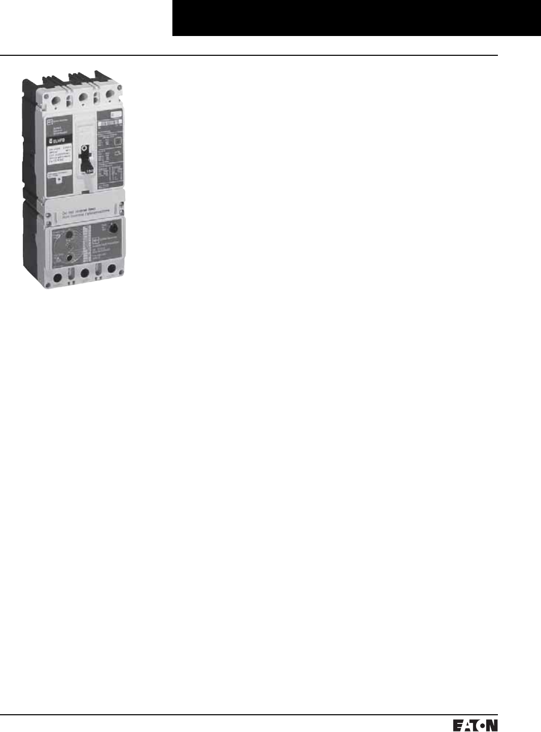
March 1999
PG.74A.01.T.E
Cutler-Hammer 113
Molded Case Circuit Breakers
Series C Earth Leakage Circuit Breakers
General Information
Series C Earth Leakage Breakers
offer superior Class 1 ground fault
protection and improved ground
fault coordination capability.
Earth leakage ground fault protection
differs from other types of systems in
its level of sensitivity. The sensitivity
of traditional devices is limited by the
cumulative error of the residual cur-
rent sensors and the placement of
the phase and neutral conductors
inside the current sensor.
Leakage breakers are zero sequence
sensing devices. They are factory
supplied with a single sensor and
ground fault relay built-in. This tech-
nique allows for protection sensitivi-
ties down to the 30 milliampere level.
Leakage breakers are provided with a
full complement of easy adjust-
ments. The ground fault pickup set-
ting is adjustable from 0.03 to 30
amperes in eight steps, and the
ground fault time delay setting is
adjustable from instantaneous to 2.0
seconds in six steps. When the
pickup is set to 30 mA, the time delay
setting defaults internally to instanta-
neous only. Increased selectivity pro-
vides for improved coordination with
upstream and downstream ground
fault devices as well as the flexibility
to adjust for transient currents.
Applications
Three-Phase, Four-Wire Loads
For three-phase applications with
line-to-neutral loads, select 4-pole
earth leakage breakers and wire the
neutral through the fourth (right) pole.
Three-Phase, Three-Wire Loads
For applications with only three-
phase, three-wire, line-to-line con-
nected loads, select 3-pole earth
leakage breakers.
Single-Phase Loads
For single-phase, two-wire or three-
wire applications, use a 3-pole earth
leakage breaker and connect all con-
ductors through the breaker.
Accessories
Optional Factory Installed
Internal Accessories
Earth leakage breakers use the same
internal accessories as standard F-,
J- and K-Frame Series C Breakers.
Internal accessories fit in the right-
hand pole space and are available as
factory modifications only.
Optional External Accessories
Series C Earth Leakage Breakers use
the same external accessories as the
standard F-, J- and K-Frame circuit
breakers.
Typical Series C Earth
Leakage Circuit Breaker
PG.74A.01.T.E
Cutler-Hammer
114 March 1999
Molded Case Circuit Breakers
Series C Earth Leakage Circuit Breakers
Selection Guide and Ordering Information
F-Frame Earth Leakage Ground Fault Breakers UL 489 and UL 1053 – Catalog Numbers
Amperes➂25 kA at 480 VAC 65 kA at 480 VAC 100 kA at 480 VAC
3-Pole 4-Pole 3-Pole 4-Pole 3-Pole 4-Pole
35
40
45
50
60
70
80
90
100
110
125
150
ELFD3035L
ELFD3040L
ELFD3045L
ELFD3050L
ELFD3060L
ELFD3070L
ELFD3080L
ELFD3090L
ELFD3100L
ELFD3110L
ELFD3125L
ELFD3150L
ELFD4035L
ELFD4040L
ELFD4045L
ELFD4050L
ELFD4060L
ELFD4070L
ELFD4080L
ELFD4090L
ELFD4100L
ELFD4110L
ELFD4125L
ELFD4150L
ELHFD3035L
ELHFD3040L
ELHFD3045L
ELHFD3050L
ELHFD3060L
ELHFD3070L
ELHFD3080L
ELHFD3090L
ELHFD3100L
ELHFD3110L
ELHFD3125L
ELHFD3150L
ELHFD4035L
ELHFD4040L
ELHFD4045L
ELHFD4050L
ELHFD4060L
ELHFD4070L
ELHFD4080L
ELHFD4090L
ELHFD4100L
ELHFD4110L
ELHFD4125L
ELHFD4150L
ELFDC3035L
ELFDC3040L
ELFDC3045L
ELFDC3050L
ELFDC3060L
ELFDC3070L
ELFDC3080L
ELFDC3090L
ELFDC3100L
ELFDC3110L
ELFDC3125L
ELFDC3150L
ELFDC4035L
ELFDC4040L
ELFDC4045L
ELFDC4050L
ELFDC4060L
ELFDC4070L
ELFDC4080L
ELFDC4090L
ELFDC4100L
ELFDC4110L
ELFDC4125L
ELFDC4150L
J-Frame Earth Leakage Ground Fault Breakers UL 489 and UL 1053 – Catalog Numbers
Amperes 35 kA at 480 VAC 65 kA at 480 VAC 100 kA at 480 VAC
3-Pole 4-Pole 3-Pole 4-Pole 3-Pole 4-Pole
100
125
150
175
200
225
250
ELJD3100
ELJD3125
ELJD3150
ELJD3175
ELJD3200
ELJD3225
ELJD3250
ELJD4100
ELJD4125
ELJD4150
ELJD4175
ELJD4200
ELJD4225
ELJD4250
ELHJD3100
ELHJD3125
ELHJD3150
ELHJD3175
ELHJD3200
ELHJD3225
ELHJD3250
ELHJD4100
ELHJD4125
ELHJD4150
ELHJD4175
ELHJD4200
ELHJD4225
ELHJD4250
ELJDC3100
ELJDC3125
ELJDC3150
ELJDC3175
ELJDC3200
ELJDC3225
ELJDC3250
ELJDC4100
ELJDC4125
ELJDC4150
ELJDC4175
ELJDC4200
ELJDC4225
ELJDC4250
K-Frame Earth Leakage Ground Fault Breakers UL 489 and UL 1053 – Catalog Numbers
Amperes 35 kA at 480 VAC 65 kA at 480 VAC 100 kA at 480 VAC
3-Pole 4-Pole 3-Pole 4-Pole 3-Pole 4-Pole
200
225
250
300
350
400
ELKD3200
ELKD3225
ELKD3250
ELKD3300
ELKD3350
ELKD3400
ELKD4200
ELKD4225
ELKD4250
ELKD4300
ELKD4350
ELKD4400
ELHKD3200
ELHKD3225
ELHKD3250
ELHKD3300
ELHKD3350
ELHKD3400
ELHKD4200
ELHKD4225
ELHKD4250
ELHKD4300
ELHKD4350
ELHKD4400
ELKDC3200
ELKDC3225
ELKDC3250
ELKDC3300
ELKDC3350
ELKDC3400
ELKDC4200
ELKDC4225
ELKDC4250
ELKDC4300
ELKDC4350
ELKDC4400
Standard Line and Load Terminals – Included with Breaker
Frame Wire Type (Number) Range of Conductors Terminal Material
F-Frame
F-Frame
35-100A
110-150A
Cu/Al
Cu/Al
(1) #14-1/0
(1) #4-4/0
Steel
Stainless Steel
J-Frame 100-250A Cu/Al (1) #4-250 kcmil Aluminum
K-Frame
K-Frame
200-350A
400A
Cu/Al
Cu/Al
(1) 250-500 kcmil
(2) 3/0-250 kcmil
Aluminum
Aluminum
Optional K-Frame Line and Load Terminals – Order Separately
Wire Type (Number) Range of Conductors Terminal Material Catalog Number
Cu/Al
Cu/Al
(2) 250 kcmil
(1) 500 kcmil
Aluminum
Aluminum
3TA401K➀
Cu/Al
Cu/Al
(2) 250 kcmil
(1) 500 kcmil
Aluminum
Aluminum
4TA401K➁
Cu (1) 3-350 kcmil Copper T300K
Cu (1) 3-350 kcmil Copper T300K
Cu (1) 250-500 kcmil Copper T350K
Cu (1) 250-500 kcmil Copper T350K
Cu (1) 3/0-250 kcmil Copper 3T400K➀
Cu (1) 3/0-250 kcmil Copper 3T400K➁➀Package of 3 terminals.
➁Package of 4 terminals.
➂15, 20, 25, and 30 ampere available.
F-Frame HMCP with Earth Leakage Ground Fault
Continuous Amperes Catalog Number 3-Pole
3ELHMCP003A0C
7ELHMCP007C0C
15 ELHMCP015E0C
25 ELHMCP025X0C
30 ELHMCP030H1C
50 ELHMCP050K2C
70 ELHMCP070M2C
100 ELHMCP100R3C
150 ELHMCP150T4C
150 ELHMCP150U4C
3ELHMCP003A0LC
7ELHMCP007C0LC
15 ELHMCP015E0LC
25 ELHMCP025D0C
30 ELHMCP030H1LC
50 ELHMCP050G2C
70 ELHMCP070J2C
100 ELHMCP100L3C
–ELHMCP024D0IC
–ELHMCP050G2IC
–ELHMCP070J2IC
100 ELHMCP100K3C
HMCPs for Application with Motor Starters
Equipped with Electrical Overload Relays
3ELHMCPS003A0C
7ELHMCPS007C0C
15 ELHMCPS015E0C
30 ELHMCPS030H1C
50 ELHMCPS050K2C
100 ELHMCPS100R3C
150 ELHMCPS150T4C
150 ELHMCPS140U4C
J-Frame HMCP with Earth Leakage Ground Fault
Continuous Amperes Catalog Number 3-Pole
250 ELHMCP250A5
ELHMCP250C5
ELHMCP250D5
ELHMCP250F5
ELHMCP250G5
ELHMCP250J5
ELHMCP250K5
ELHMCP250L5
ELHMCP250W5
400 ELHMCP400D5
ELHMCP400F5
ELHMCP400G5
ELHMCP400J5
ELHMCP400K5
Time/Current Curves, Dimension Sheets, Application Data
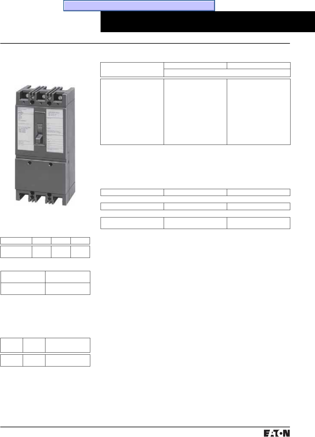
March 1999
PG.74A.01.T.E
Cutler-Hammer 115
Molded Case Circuit Breakers
Non-Fused Current Limiting
Interrupting Capacity Ratings
Circuit
Breaker
Type
Volts Ac
(50/60 Hz)
Interrupting Capacity
(Symmetrical Amperes) (kA)
FCL 240
480
200
150
Approximate Shipping Weight, Lbs. (kg)
2-Pole 9
(4.082)
3-Pole 9
(4.082)
➀2-pole breakers are supplied in 3-pole frames
with current carrying parts omitted from the
center pole.
Type FCL Breaker
Listed with Underwriters Labora-
tories, Inc. except as noted.
Type FCL breakers are not defined in
Federal Specification W-C-375-b.
Line and Load Terminals
Breakers listed include line and load terminals. Terminals are Underwriters
Laboratories, Inc. listed for wire sizes and types listed below. When used with
aluminum cable, use joint compound. To order optional aluminum terminals,
add suffix “Z” to breaker catalog number listed.
Maximum Breaker Amperes Wire Type AWG Wire Range
Standard Pressure Terminals
100 Al/Cu #14-1/0
Optional Al/Cu Pressure Terminals
50
100
Al/Cu
Al/Cu
#14-#4
#4-4/0
Type FCL Current Limit-R Thermal-Magnetic Circuit Breakers
15 to 100 Amperes, 480 Volts Ac
Non-Interchangeable Trip, Line and
Load Terminals Included
On all 3-phase Delta, Grounded
B phase applications, refer to
Cutler-Hammer.
Dimensions / Weights
Dimensions, Inches
Number of Poles Width Height Depth
2-3 4.125
(104.78)
8.75
(222.25)
3.375
(85.73)
Maximum Continuous
Ampere Rating
@ 40°C
2-Pole➀3-Pole
Catalog Number
15
20
25
30
35
40
45
50
60
70
80
90
100
FCL2015L
FCL2020L
FCL2025L
FCL2030L
FCL2035L
FCL2040L
FCL2045L
FCL2050L
FCL2060L
FCL2070L
FCL2080L
FCL2090L
FCL2100L
FCL3015L
FCL3020L
FCL3025L
FCL3030L
FCL3035L
FCL3040L
FCL3045L
FCL3050L
FCL3060L
FCL3070L
FCL3080L
FCL3090L
FCL3100L
Time/Current Curves, Dimension Sheets, Application Data
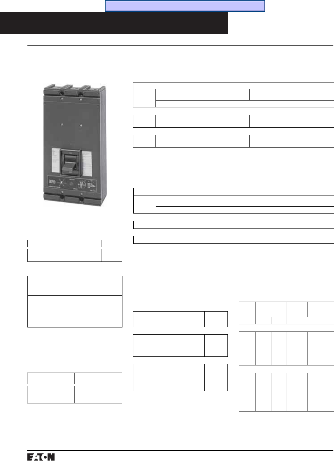
PG.74A.01.T.E
Cutler-Hammer
116 March 1999
Molded Case Circuit Breakers
Non-Fused Current Limiting
Listed with Underwriters Labora-
tories, Inc. except as noted.
Type LCL breakers are not defined in
Federal Specification W-C-375-b.
Type LCL Breaker
Type LCL Current Limit-R Electronic Circuit Breakers
Interrupting Capacity Ratings
Circuit
Breaker Type
Volts Ac
(50/60 Hz)
Interrupting Capacity
(Symmetrical Amperes) (kA)
LCL 240
480
600
200
200
100
Approximate Shipping Weight, Lbs. (kg)
Standard
2-Pole 32
(14.515)
3-Pole 32
(14.515)
With Ground Fault
3-Pole 36
(16.329)
125 to 400 Amperes, 600 Volts Ac
with Solid State Trip Units
On all 3-phase Delta, Grounded
B phase applications, refer to
Cutler-Hammer.
Instruction Leaflet/FRED Number 15257
Standard Breakers 600 Volts Ac, 50/60 Hz
Complete breaker requires frame, rating plug and terminals
Frame Only
Poles➀Standard (Long Delay, Mag-
netic Trip and Current Limiting)
Magnetic Only➁ and
Current Limiting
Long Delay, Magnetic Trip and Adjustable Short
Delay Time (.08-.28 seconds), and Current Limiting
Catalog Number
Types LCL and LCLA 250 Ampere Frame (125-250 Amperes)
2
3
LCL2250F
LCL3250F
LCL2250FM
LCL3250FM
LCLA2250F
LCLA3250F
Type LCL and LCLA 400 Ampere Frame (200-400 Amperes)
2
3
LCL2400F
LCL3400F
LCL2400FM
LCL3400FM
LCLA2400F
LCLA3400F
Breakers with Built-in Ground Fault Protection
Complete breaker requires frame, rating plug and terminals – extra current
transformer included for neutral.
Frame Only
Poles➀Standard (Long Delay, Magnetic Trip,
Current Limiting, and Ground Fault Trip)
Long Delay, Magnetic Trip and Adjustable Short Delay Time
(.06-.22 seconds), and Ground Fault Trip and Current Limiting
Catalog Number
Types LCLG and LCLGA 250 Ampere Frame (125-250 Amperes)
3LCLG3250F LCLGA3250F
Types LCLG and LCLGA 400 Ampere Frame (200-400 Amperes)
3LCLG3400F LCLGA3400F
Instruction Leaflet/FRED Number 15495
➀2-pole breakers are supplied in 3-pole frames
with current carrying parts omitted from the
center pole.
➁UL listed recognized component.
➂Terminals shipped separately from breaker.
Terminals➂ (Order Separately)
Two terminals are required per pole.
Terminals are Underwriters Labora-
tories, Inc. listed for wire type and
range listed below. When used
with aluminum cable, use joint
compound.
Maximum
Breaker
Amperes
Wire Range, Type,
Number of Cables
Terminal
Catalog
Number
Standard Copper Pressure Terminals
225
400
1#6-350 kcmil Cu
1#4-250 kcmil Cu,
plus
1 3/0-600 kcmil Cu
T225LA
T401LA
Optional Al/Cu Pressure Terminals
225
400
1#6-350 kcmil Cu, or
1#4-350 kcmil Al
1#4-250 kcmil Al/Cu,
plus
1 3/0-600 kcmil Al/Cu
TA225LA1
TA400LA1
Rating Plug Selection Data
Rating plugs listed below are for
both standard breakers and breakers
with built-in ground fault protection.
Rating Plugs Only (For 2- or 3-Pole Frames)
Contin-
uous
Ampere
Rating
Magnetic Trip
Setting, Amperes
Fixed
Rating
Plugs
Adjustable
Rating
Plugs➃
Low High Catalog Number
Types LCL and LCLA 250 Ampere Frames
125
150
175
200
225
250
375
450
525
600
675
750
1125
1350
1575
1800
2025
2250
2LCL125
2LCL150
2LCL175
2LCL200
2LCL225
2LCL250
–
–
A2LCL175➄
A2LCL200
A2LCL225
A2LCL250➅
Types LCL and LCLA 400 Ampere Frames
200
225
250
275
300
350
400
400
450
500
550
600
700
800
1600
1800
2000
2200
2400
2800
3200
4LCL200
4LCL225
4LCL250
4LCL275
4LCL300
4LCL350
4LCL400
–
–
–
–
A4LCL300➄
A4LCL350
A4LCL400➅
Dimensions / Weights
Dimensions, Inches
Number of Poles Width Height Depth
2-3 16
(406.40)
8.25
(209.56)
4.0625
(103.19)
➃Adjustable 70 to 100% except as noted.
➄Adjustable 75 to 100%.
➅Adjustable 50 to 100%.
Time/Current Curves, Dimension Sheets, Application Data
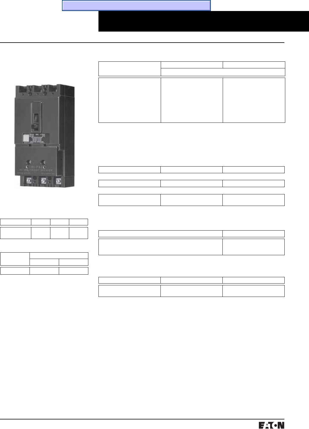
March 1999
PG.74A.01.T.E
Cutler-Hammer 117
Molded Case Circuit Breakers
Fused Current Limiting
➀2-pole breakers are supplied in 3-pole frames
with current carrying parts omitted from the
center pole.
Type Tri-Pac FB Breaker
Type FB Tri-Pac Thermal-Magnetic Circuit Breakers
Approximate Shipping Weight, Lbs. (kg)
Breaker Complete Breaker
2-Pole 3-Pole
Tri-Pac FB 10.5 11.5
Line and Load Terminals
Breakers listed include line and load terminals. Terminals are Underwriters
Laboratories, Inc. listed for wire sizes and types listed below. When used with
aluminum cable, use joint compound. To order optional aluminum terminals,
add suffix “Z” to breaker catalog number listed.
Maximum Breaker Amperes Wire Type AWG Wire Range
Standard Pressure Terminals
100 Al/Cu #14-1/0
Optional Al/Cu Pressure Terminals
50
100
Al/Cu
Al/Cu
#14-#4
#4-4/0
Replacement Current Limiters and Housing Assembly
Current Limiters: One required per pole.
Application Catalog Number
Supplied as standard in Type FB Tri-Pac breakers rated 15-100 amperes.
Replaces 200FBP03 formerly supplied on 15-40 ampere ratings, and
500FBP07 formerly supplied on 50-100 ampere ratings.
100FBP06
Refer to CAT.71.01.T.E for complete application information.
Current Limiter Housing Assembly Complete with Current Limiter
Ampere Rating Poles Style Number
15-100
15-100
2
3
176C593G09
176C593G10
15 to 100 Amperes, 600 Volts Ac,
250 Volts Dc, Replaceable Current
Limiters
Listed with Underwriters Labora-
tories, Inc. except as noted.
Tri-Pac FB breakers meet the
requirements for Class 16a, 16b, 17a
and 26a circuit breakers as defined
in Federal Specification W-C-375b.
Interrupting Capacity Ratings
Underwriters Laboratories, Inc.
Listed
600 Volts Ac Maximum: 200,000
Amperes Symmetrical
Based on NEMA Test Procedures
250 Volts Dc Maximum: 100,000
Amperes.
On all 3-phase Delta, Ground B phase
applications, refer to Cutler-Hammer.
Dimensions / Weights
Dimensions, Inches
Number of Poles Width Height Depth
2-3 4.125
(104.78)
8.75
(222.25)
3.5
(88.90)
Maximum Continuous
Ampere Rating
@ 40°C
2-Pole➀3-Pole
Catalog Number (Current Limiters Included)
15
20
30
40
50
60
70
90
100
FB2015PL
FB2020PL
FB2030PL
FB2040PL
FB2050PL
FB2060PL
FB2070PL
FB2090PL
FB2100PL
FB3015PL
FB3020PL
FB3030PL
FB3040PL
FB3050PL
FB3060PL
FB3070PL
FB3090PL
FB3100PL
Time/Current Curves, Dimension Sheets, Application Data
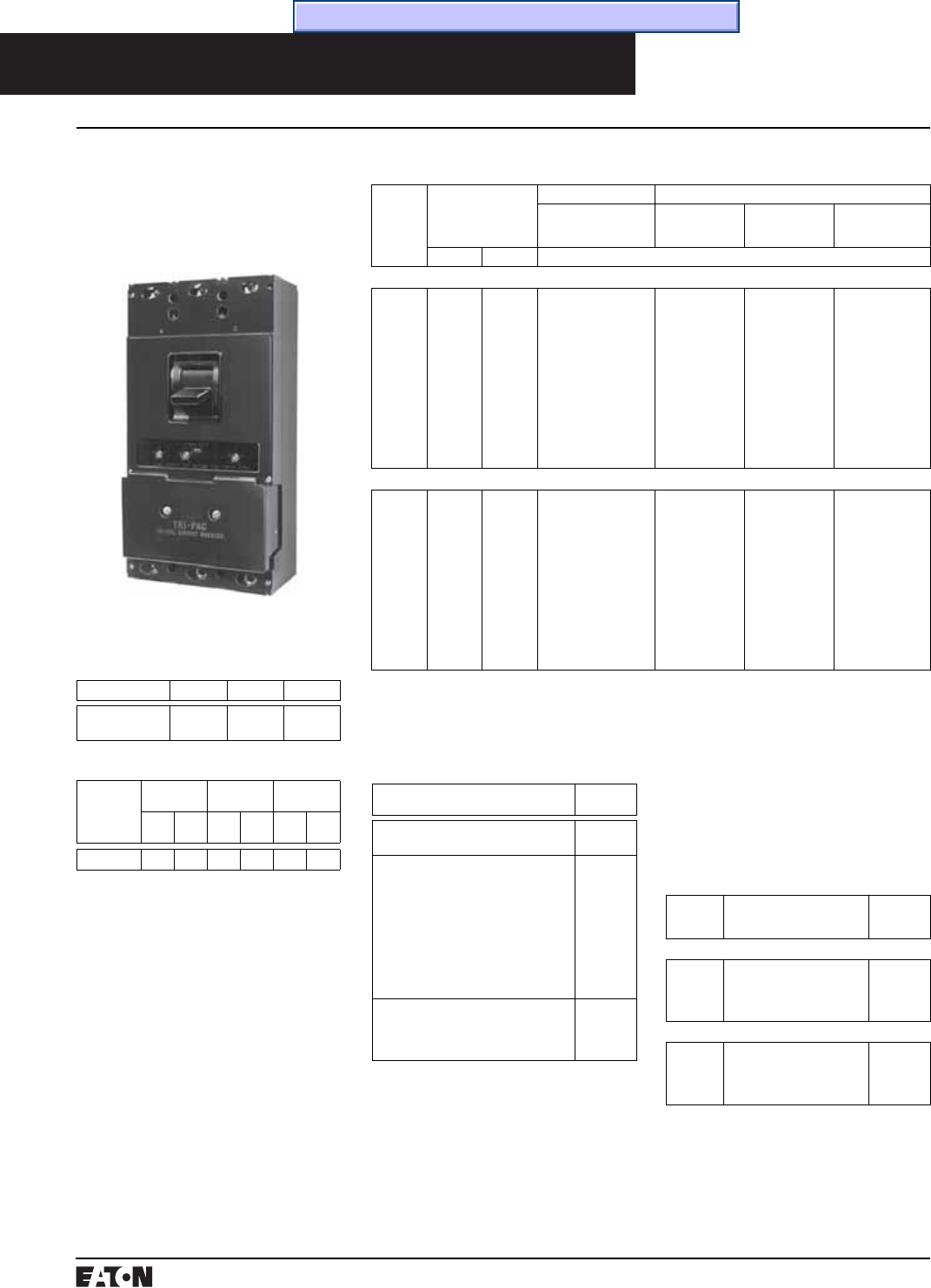
PG.74A.01.T.E
Cutler-Hammer
118 March 1999
Continu-
ous
Ampere
Rating
@40°C
Magnetic Trip Setting
Amperes➃
Complete Breaker Shipped as Frame, Trip Units, Limiters and Terminals➄
Includes Pressure Type
Copper Terminals➄
Frame Only Trip Unit Only Current Limiter
1 Required per
Pole
Low High Catalog Number
2 Poles, 600 Volts Ac, 250 Volts Dc➅
70
90
100
125
150
175
200
225
250
300
350
400
350
450
500
625
750
875
1000
1125
1250
1500
1750
2000
700
900
1000
1250
1500
1750
2000
2250
2500
3000
3500
4000
LA2070PR
LA2090PR
LA2100PR
LA2125PR
LA2150PR
LA2175PR
LA2200PR
LA2225PR
LA2250PR
LA2300PR
LA2350PR
LA2400PR
LA2400PRF
LA2400PRF
LA2400PRF
LA2400PRF
LA2400PRF
LA2400PRF
LA2400PRF
LA2400PRF
LA2400PRF
LA2400PRF
LA2400PRF
LA2400PRF
LA2070PT
LA2090PT
LA2100PT
LA2125PT
LA2150PT
LA2175PT
LA2200PT
LA2225PT
LA2250PT
LA2300PT
LA2350PT
LA2400PT
200LAP08
200LAP08
200LAP08
200LAP08
200LAP08
200LAP08
200LAP08
400LAP10
400LAP10
400LAP10
400LAP10
400LAP10
3 Poles, 600 Volts Ac, 250 Volts Dc
70
90
100
125
150
175
200
225
250
300
350
400
350
450
500
625
750
875
1000
1125
1250
1500
1750
2000
700
900
1000
1250
1500
1750
2000
2250
2500
3000
3500
4000
LA3070PR
LA3090PR
LA3100PR
LA3125PR
LA3150PR
LA3175PR
LA3200PR
LA3225PR
LA3250PR
LA3300PR
LA3350PR
LA3400PR
LA3400PRF
LA3400PRF
LA3400PRF
LA3400PRF
LA3400PRF
LA3400PRF
LA3400PRF
LA3400PRF
LA3400PRF
LA3400PRF
LA3400PRF
LA3400PRF
LA3070PT
LA3090PT
LA3100PT
LA3125PT
LA3150PT
LA3175PT
LA3200PT
LA3225PT
LA3250PT
LA3300PT
LA3350PT
LA3400PT
200LAP08
200LAP08
200LAP08
200LAP08
200LAP08
200LAP08
200LAP08
400LAP10
400LAP10
400LAP10
400LAP10
400LAP10
Instruction Leaflet/FRED Number 14551 for Trip Unit and Fuse
Dimensions / Weights
Dimensions, Inches
Number of Poles Width Height Depth
2-3 8.25
(209.56)
16
(406.40)
4.75
(113.54)
Molded Case Circuit Breakers
Fused Current Limiting
Terminals➄
Two terminals are required per pole.
Terminals are Underwriters Labora-
tories, Inc. listed for wire size and
type listed below. When used with
aluminum conductors, use joint
compound. To order optional alumi-
num terminals, add suffix “Z” to
complete breaker catalog number.
Maximum
Breaker
Amperes
Wire Range, Type,
Number of Cables
Terminal
Catalog
Number
Standard Copper Pressure Terminals
225
225➆
400
1 #6-350 kcmil Cu
1 #6-250 kcmil Cu
1 #4-250 kcmil Cu, plus
1 3/0-600 kcmil Cu
T225LA
T225LBF
T401LA
Optional Al/Cu Pressure Terminals
225
400
1 #6-350 kcmil Cu, or
1 #4-350 kcmil Cu/Al
1 #4-250 kcmil Al/Cu, plus
1 3/0-600 kcmil Al/Cu
TA225LA1
TA400LA1
Instruction Leaflet/FRED Number 13732
Type Tri-Pac LA Breaker
Listed with Underwriters Labora-
tories, Inc. except as noted.
Tri-Pac LA breakers meet the
requirements for Class 16a, 16b, 17a
and 26a circuit breakers as defined in
Federal Specification W-C-375b.
Interrupting Capacity Ratings
Underwriters Laboratories, Inc.
Listed
600 Volts Ac Maximum: 200,000
Amperes Symmetrical
Based on NEMA Test Procedures
250 Volts Dc Maximum: 100,000
Amperes.
On all 3-phase Delta, Ground B phase
applications, refer to Cutler-Hammer.
Type LA Tri-Pac Thermal-Magnetic Circuit Breakers
70 to 400 Amperes, 600 Volts Ac,
250 Volts Dc, 2-, 3-Pole, Inter-
changeable Trip, Replaceable
Current Limiters
Approximate Shipping Weight, Lbs. (kg)
Breaker Complete
Breaker
Frame
Only
Trip
Unit
2-
Pole
3-
Pole
2-
Pole
3-
Pole
2-
Pole
3-
Pole
Tri-Pac LA 29.75 34 23.5 25 2.25 3
Current Limiters
Included with breaker, one required
per pole.
Application Catalog
Number
Supplied as standard on ratings
through 200 amperes.
200LAP08
Supplied as standard on 225 through
400 ampere ratings, optional on lower
ratings when a higher “cross-over
point” is desired. (Above two limiters
replace 800LAP12 formerly supplied
as standard on all ratings, 600LAP09
optional on all ratings through 300
amperes, 300LAP05 optional on rat-
ings through 150 amperes, and spe-
cial rating limiter 1000LAP14.)
400LAP10
Special rating where a higher “cross-
over point” is desired on 200 ampere
and higher ratings (Replaces limiter
1500LAP20)
500LAP15
➁➂
➀New limiters suitable for replacement in
existing breakers by using plug-in conductor
from old limiter (instructions included with
limiter). Instruction Leaflet/FRED Number
14824
➁Not listed with Underwriters Laboratories, Inc.
➂Protection based on 100,000 ampere maxi-
mum fault, 480 volts maximum.
➃Set on high side, adjustable to lower limits.
➄Terminals shipped separately from breakers.
➅2-pole breakers or trips are supplied in 3-pole
frames with current carrying parts omitted
from the center pole.
➆Optional terminal.
Time/Current Curves, Dimension Sheets, Application Data
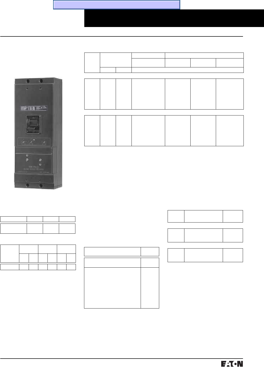
March 1999
PG.74A.01.T.E
Cutler-Hammer 119
Molded Case Circuit Breakers
Fused Current Limiting
Type Tri-Pac NB Breaker
Current Limiters
Included with breaker, one required
per pole.
Application Catalog
Number
Supplied as standard on ratings
through 500 amperes.
500NBP12
Supplied as standard on 600 through
800 ampere ratings, optional on
lower ratings when a higher “cross-
over point” is desired.
Above two limiters replace
1000NBP14 formerly supplied on rat-
ings up to 600 amperes, 1500NBP20
supplied on 700 amperes, and
2500NBP25 supplied on 800 amperes.
800NBP20
Type NB Tri-Pac Thermal-Magnetic Circuit Breakers
➀Dc rating applies to 350 amperes maximum
thermal or to magnetic only breakers.
➁Shipped separately from breaker
➂2-pole breakers or trips are supplied in 3-pole
frames with current carrying parts omitted
from the center pole.
➃60 Hz Ac only.
300 to 800 Amperes, 600 Volts Ac,
250 Volts Dc➀, 2-, 3-Pole, Inter-
changeable Trip, Replaceable
Current Limiters
Approximate Shipping Weight, Lbs. (kg)
Breaker Complete
Breaker
Frame
Only
Trip
Unit
2-
Pole
3-
Pole
2-
Pole
3-
Pole
2-
Pole
3-
Pole
Tri-Pac NB 62 75 58 65 3.5 4
Listed with Underwriters Labora-
tories, Inc. except as noted.
Tri-Pac NB breakers meet the
requirements for Class 16b, 17a and
26a circuit breakers as defined in
Federal Specification W-C-375b.
Interrupting Capacity Ratings
Underwriters Laboratories, Inc.
Listed
600 Volts Ac Maximum: 200,000
Amperes Symmetrical
Based on NEMA Test Procedures
250 Volts Dc Maximum➀: 100,000
Amperes.
On all 3-phase Delta, Grounded
B phase applications, refer to
Cutler-Hammer.
Terminals➁
Two terminals are required per pole.
Terminals are Underwriters Labora-
tories, Inc. listed for wire size and
type listed below. When used with
aluminum conductors, use joint
compound. To order optional alumi-
num terminals, add suffix “Z” to
complete breaker catalog number.
Maximum
Ampere
Rating
Wire Range, Type,
Number of Cables
Terminal
Catalog
Number
Standard Copper Pressure Terminals
350
700
800
1 #1-600 kcmil Cu
2 2/0-500 kcmil Cu
3 3/0-500 kcmil Cu
T350NB
T700NB1
T1000NB1
Optional Al/Cu Pressure Terminals
700
800
800
2 #1-500 kcmil Al/Cu
3 3/0-400 kcmil Al/Cu
3 500-750 kcmil Al/Cu
TA700NB1
TA1000NB1
TA1201NB1
Continu-
ous
Ampere
Rating
@40°C
Magnetic Trip Setting
Amperes➃
Complete Breaker Shipped as Frame, Trip Units, Limiters and Terminals
Includes Pressure Type
Copper Terminals➄
Frame Only Trip Unit Only Current Limiter
1 Required per Pole
Low High Catalog Number
2 Poles, 600 Volts Ac, 250 Volts Dc➀➂
300
350
400➃
500➃
600➃
700➃
800➃
1500
1750
2000
2500
3000
3000
3000
3000
3500
4000
5000
6000
6000
6000
NB2300P
NB2350P
NB2400P
NB2500P
NB2600P
NB2700P
NB2800P
NB2800PF
NB2800PF
NB2800PF
NB2800PF
NB2800PF
NB2800PF
NB2800PF
NB2300PT
NB2350PT
NB2400PT
NB2500PT
NB2600PT
NB2700PT
NB2800PT
500NBP12
500NBP12
500NBP12
500NBP12
800NBP20
800NBP20
800NBP20
3 Poles, 600 Volts Ac Only
300
350
400➃
500➃
600➃
700➃
800➃
1500
1750
2000
2500
3000
3000
3000
3000
3500
4000
5000
6000
6000
6000
NB3300P
NB3350P
NB3400P
NB3500P
NB3600P
NB3700P
NB3800P
NB3800PF
NB3800PF
NB3800PF
NB3800PF
NB3800PF
NB3800PF
NB3800PF
NB3300PT
NB3350PT
NB3400PT
NB3500PT
NB3600PT
NB3700PT
NB3800PT
500NBP12
500NBP12
500NBP12
500NBP12
800NBP20
800NBP20
800NBP20
Instruction Leaflet/FRED Number 13771 for Trip Unit and Fuse
Dimensions / Weights
Dimensions, Inches
Number of Poles Width Height Depth
2-3 8.25
(209.56)
22
(558.80)
5.5
(139.70)
Time/Current Curves, Dimension Sheets, Application Data
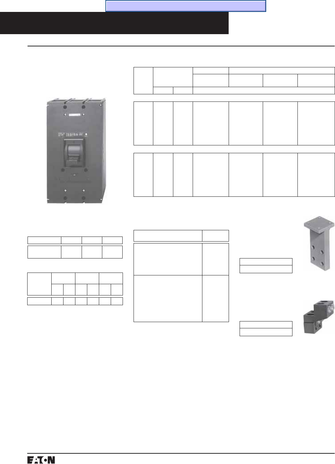
PG.74A.01.T.E
Cutler-Hammer
120 March 1999
Bus Bar Connectors➅
“T” Connector for
Cu/Al Bus
Two required per pole.
For rear bus connection.
Accepts up to four bus
bolts. May be rotated 90º.
Catalog Number
BA2000B
Molded Case Circuit Breakers
Fused Current Limiting
➃Magnetic only trip units are available. Order
by description.
➄2-pole breakers are supplied in 3-pole frames
with current carrying parts omitted from
center pole.
➅Not listed with Underwriters
Laboratories, Inc.
Type Tri-Pac PB Breaker
Current Limiters
Included with breaker, one required
per pole.
Application Catalog
Number
Supplied as standard on ratings
through 1000 amperes. (Replaces
limiter 1500PBPR30 formerly sup-
plied on 600 and 700 ampere rat-
ings, and 3000 PBPR27 supplied on
800-1000 ampere ratings.
1000PBPR20
Supplied as standard on 1200
through 1600 ampere ratings.
Optional on lower ratings where a
higher “cross-over point” is
desired. (Replaces limiter
4000PBR30 formerly supplied on
1200 through 1400 ampere ratings,
and 5000PBPR42 supplied on 1600
ampere ratings.
1600PBPR30
Type PB Tri-Pac Thermal-Magnetic Circuit Breakers
600 to 1600 Amperes, 600 Volts Ac,
60 Hertz Ac➀, 250 Volts Dc➁,
2-, 3- Poles Interchangeable Trip,
Replaceable Current Limiters
Approximate Shipping Weight, Lbs. (kg)
Breaker Complete
Breaker
Frame
Only
Trip
Unit
2-
Pole
3-
Pole
2-
Pole
3-
Pole
2-
Pole
3-
Pole
Tri-Pac PB 148 179 106 120 18 23
Listed with Underwriters Labora-
tories, Inc. except as noted.
Tri-Pac PB breakers meet the
requirements for Class 17a and 26a
circuit breakers as defined in Federal
Specification W-C-375b.
Interrupting Capacity Ratings
Underwriters Laboratories, Inc.
Listed
600 Volts Ac Maximum: 200,000
Amperes Symmetrical
Based on NEMA Test Procedures
250 Volts Dc➁: 100,000 Amperes.
On all 3-phase Delta, Grounded
B phase applications, refer to
Cutler-Hammer.
Cable Connector
(Optional)
For “T” connector.
Accepts four 600 kcmil
copper cables.
Style Number
505C706G04
Special Breakers➅
Magnetic Only Type Tri-Pacs:
Available on request.
Continu-
ous
Ampere
Rating
@40°C
Ac Magnetic Trip Set-
ting (Set on High Side,
Adjustable to Lower
Limits)
Complete Breaker Shipped as Frame, Trip Unit Current Limiters and Connectors
Includes Rear
“T” Connectors➄
Frame Only Trip Unit Only➃Current Limiter
1 Required per Pole
Low High Catalog Number
2 Poles, 600 Volts Ac➄
600
700
800
900
1000
1200
1400
1600
1500
1500
1500
1500
1500
2000
2500
3000
5000
5000
5000
5000
5000
6000
7000
8000
PB2600PR
PB2700PR
PB2800PR
PB2900PR
PB21000PR
PB21200PR
PB21400PR
PB21600PR
PB21600PRF
PB21600PRF
PB21600PRF
PB21600PRF
PB21600PRF
PB21600PRF
PB21600PRF
PB21600PRF
PB2600PRT
PB2700PRT
PB2800PRT
PB2900PRT
PB21000PRT
PB21200PRT
PB21400PRT
PB21600PRT
1000PBPR20
1000PBPR20
1000PBPR20
1000PBPR20
1000PBPR20
1600PBPR30
1600PBPR30
1600PBPR30
3 Poles, 600 Volts Ac Only
600
700
800
900
1000
1200
1400
1600
1500
1500
1500
1500
1500
2000
2500
3000
5000
5000
5000
5000
5000
6000
7000
8000
PB3600PR
PB3700PR
PB3800PR
PB3900PR
PB31000PR
PB31200PR
PB31400PR
PB31600PR
PB31600PRF
PB31600PRF
PB31600PRF
PB31600PRF
PB31600PRF
PB31600PRF
PB31600PRF
PB31600PRF
PB3600PRT
PB3700PRT
PB3800PRT
PB3900PRT
PB31000PRT
PB31200PRT
PB31400PRT
PB31600PRT
1000PBPR20
1000PBPR20
1000PBPR20
1000PBPR20
1000PBPR20
1600PBPR30
1600PBPR30
1600PBPR30
➀Higher frequency calibration not available.
Minimum of 50 Hz calibration available on
special order.
➁250 volts Dc rating applies only to magnetic
only breakers.
➂Shipped separately from breaker.
Dimensions / Weights
Dimensions, Inches
Number of Poles Width Height Depth
2-3 12.0625
(306.39)
22.125
(561.98)
9.0625
(230.19)
Time/Current Curves, Dimension Sheets, Application Data
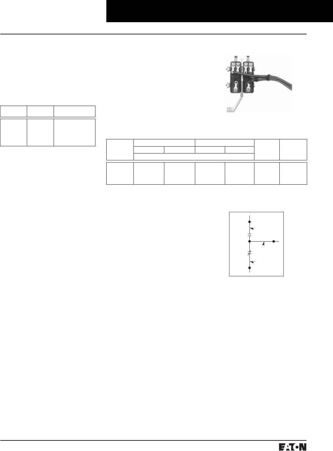
March 1999
PG.74A.01.T.E
Cutler-Hammer 121
Molded Case Circuit Breakers
Accessories for Current Limiting Circuit Breakers
Alarm Switch
For light or alarm indication when
breaker trips. Does not function with
manual operation. Automatically
resets when breaker is relatched.
Standard leads extend 18 inches out-
side of breaker. Longer leads may be
specified. Not field mountable.
Alarm Switch Contact Rating (Non
Inductive) LA Tri-Pac: 10 amperes,
120 volt Ac; 5A, 240 volt Ac.
Breaker
Frame
Normal
Pole Meeting
Contact Operation
(Specific Type Desired)
FCL
LA Tri-Pac
NB Tri-Pac
PB Tri-Pac
LCL
Center
Left
Left
Left
Left➀
Make or Break
Make or Break
Make or Break
Make or Break
Make or Break
➀When alarm switch is used in conjunction
with auxiliary switch, the auxiliary switch is
rated 250 volts max., 5 amperes maximum.
➁Left-hand mounting is standard unless other-
wise specified.
➂All switches are multiples of 1A-1B with a
common electrical connection (See diagram
above).
➃Field mounting voids UL listing of breaker
except on NB Tri-Pac and PB Tri-Pac break-
ers.
➄For Dc applications refer to factory.
➅Right-hand mounting only.
Auxiliary Switch➁
For auxiliary control circuits. Minia-
ture switches mount within breaker.
Commonly used for remote indica-
tion of open or closed breaker and
electrically interlocking component
control circuits. “A” contacts are
closed when breaker is closed. “B”
contacts are open when breaker is
closed. Standard leads extend 18
inches outside of breaker. Longer
leads may be specified.
Black Lead
Blue Lead
Red Lead
Instruction Leaflet/FRED Number 14535 NB Tri-Pac; 14534 PB Tri-Pac; 15279 LCL
Auxiliary Switch Attachment Kits for Field Mounting➂➃
Breaker
Type
For Right-Hand Mounting For Left-Hand Mounting Maxmum
Ac Voltage
Rating➄
Maximum
Non-Inductive
Amperes
1A-1B 2A-2B 1A-1B 2A-2B
Style Number
FCL
NB Tri-Pac
PB Tri-Pac
LCL
1369D79G03
4980D16G05
2602D32G14
–
–
4980D16G06
2602D32G15
–
1369D79G03
4980D16G12
2602D32G11
1372D49G03
–
4980D16G13
2602D32G12
1372D49G06
240
480
480
480
5
10
10
6 (10@240)
Factory Mounted
Auxiliary Switches➁
All of the above auxiliary switches
can be specified for factory mount-
ing at the same price as listed for the
kit. These attachments have the
leads out the side of the breaker and
are UL listed when factory mounted
unless other non UL listed modifica-
tions are used (except as noted).
Factory mounted switches only can
be supplied for the following break-
ers: FB Tri-Pac➅, LA Tri-Pac. Order
by description.
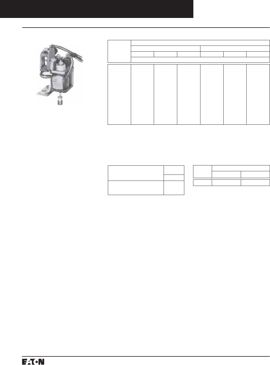
PG.74A.01.T.E
Cutler-Hammer
122 March 1999
Molded Case Circuit Breakers
Accessories for Current Limiting Circuit Breakers
Left-Hand Mounting Kits for Type LCL
Current Limiting Breakers➅
Provision to trip flux transfer shunt
trip from external 32 to 120 volt
(Dc to 60 Hz) source.➆➇
Style
Number
1372D49G22
Provision to trip flux transfer shunt
trip from external 240 to 600 volt
(50/60 Hz) source.➇➈
1372D49G32
Shunt Trip
For tripping breaker from a remote
point. A solenoid device mounts
within breaker case. Breaker trips
when coil is energized.
Shunt trips should not be used as
circuit interlocks using maintained
contact pilot devices.
A cutoff switch breaks the circuit to
the momentary rated coil when
breaker opens. Available for control
voltages up to 250 volts Dc or 600
volts Ac. Voltage and frequency
must be specified. Standard leads
extend 18 inches outside of breaker.
Longer leads may be specified.
Shunt Trip for Field Mounting➀➁➂
Voltage/Hz Breaker Type
Right-Hand Mounting Left-Hand Mounting
FCL NB Tri-Pac PB Tri-Pac FCL NB Tri-Pac PB Tri-Pac
Style Number
600/50-60 Hz
480/50-60 Hz
240/50-60 Hz
208/50-60 Hz
120/50-60 Hz
60/50-60 Hz
48/50-60 Hz
24/50-60 Hz
250 Dc
125 Dc
60 Dc
48 Dc
24 Dc
12 Dc
1369D80G15
1369D80G16
1369D80G17
1369D80G18
1369D80G19
1369D80G20
1369D80G21
1369D80G22
1369D80G23
1369D80G24
1369D80G25
1369D80G26
1369D80G27
1369D80G28
2606D58G15
2606D58G16
2606D58G17
2606D58G18
2606D58G19
2606D58G20
2606D58G21
2606D58G22
2606D58G23
2606D58G24
2606D58G25
2606D58G26
2606D58G27
2606D58G28
2606D58G15
2606D58G16
2606D58G17
2606D58G18
2606D58G19
2606D58G20
2606D58G21
2606D58G22
2606D58G23
2606D58G24
2606D58G25
2606D58G26
2606D58G27
2606D58G28
1369D80G01
1369D80G02
1369D80G03
1369D80G04
1369D80G05
1369D80G06
1369D80G07
1369D80G08
1369D80G09
1369D80G10
1369D80G11
1369D80G12
1369D80G13
1369D80G14
2606D58G01
2606D58G02
2606D58G03
2606D58G04
2606D58G05
2606D58G06
2606D58G07
2606D58G08
2606D58G09
2606D58G10
2606D58G11
2606D58G12
2606D58G13
2606D58G14
2606D58G01
2606D58G02
2606D58G03
2606D58G04
2606D58G05
2606D58G06
2606D58G07
2606D58G08
2606D58G09
2606D58G10
2606D58G11
2606D58G12
2606D58G13
2606D58G14
➀120 volt Ac ratings suitable for 55% pickup
for ground fault applications.
➁Not field mountable on non-automatic
breakers (MCS).
➂Field mounting voids breakers’ UL listing
except on NB Tri-Pac and PB Tri-Pac.
➃Right-hand mounting only.
➄Not UL listed.
➅UL listing pending. Refer to Cutler-Hammer.
➆Rated 48 volts minimum for ground fault
applications.
➇Also available factory mounted for 24 volt
Dc. Order by description.
➈Not for ground fault.
Shunt Trip Coil Data for Type LCL
Current Limiting Breakers
Shunt Trip
Voltage
Rating
Coil Inrush
Amperes Volt-Amperes
120 Ac .15 18
Instruction Leaflet/FRED Numbers
15194 14919 14940 15194 14919 14940
Factory mounted shunt trips only can be supplied for FB Tri-Pac➃➄ and
LA Tri-Pac breakers. Order by description.
Instruction Leaflet/FRED Number 15279
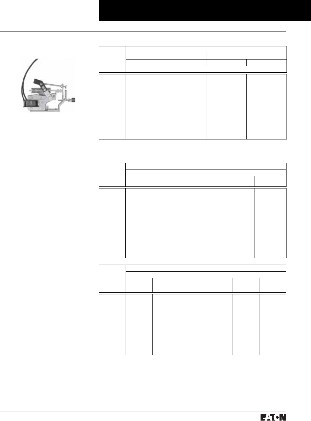
March 1999
PG.74A.01.T.E
Cutler-Hammer 123
Molded Case Circuit Breakers
Accessories for Current Limiting Circuit Breakers
Standard Undervoltage
Release➀
For undervoltage protection. A sole-
noid device mounts within breaker
case. Coil must be energized before
closing breaker. Trips breaker when
voltage drops below 40 to 60% of
coil rating. Picks up and seals in at
80% of coil rating. For line voltages
up to 250 volts Dc or 600 volts Ac.
Externally mounted resistors are
supplied for certain ratings. Stan-
dard leads extend 18 inches outside
of breaker. Longer leads may be
specified.
Note: U.V.R. attachments are not
designed for, and should not be used
as, circuit interlocks. For further
information, refer to Cutler-Hammer.
Factory Mounted
Undervoltage Releases➁
NB Tri-Pac and PB Tri-Pac undervolt-
age releases can be specified for
factory mounting at the same price
as the kit. These attachments have
the leads out the side and are
UL listed when factory mounted
unless other non-UL listed modifica-
tions are used.
Factory mounted undervoltage
releases only can be supplied for the
following breakers: FB Tri-Pac➂,
LA Tri-Pac and FCL; LCL 120 Volts
Ac only.➃ Order by description.
Undervoltage Release Attachment Kits for Field Mounting➄➅
Attachment
Voltage, Hz
Breaker Type
For Right-Hand Mounting For Left-Hand Mounting
NB Tri-Pac PB Tri-Pac NB Tri-Pac PB Tri-Pac
Style Number
24 60
48 60
120 60
208 60
240 60
480 60
600 60
12 Dc
24 Dc
48 Dc
60 Dc
125 Dc
250 Dc
–
–
373D632G01
373D632G19
373D632G02
373D632G03
373D632G04
372D032G01
372D032G02
372D032G03
–
372D032G04
372D032G05
–
5674D29G16
5674D29G09
5674D29G10
5674D29G11
5674D29G13
5674D29G14
4976D85G01
4976D85G02
4976D85G03
4976D85G04
4976D85G07
4976D85G08
–
–
373D632G05
373D632G20
373D632G06
373D632G07
373D632G08
372D032G06
372D032G07
372D032G08
–
372D032G09
372D032G10
–
5674D29G08
5674D29G01
5674D29G02
5674D29G03
5674D29G05
5674D29G06
4976D85G11
4976D85G12
4976D85G13
4976D85G14
4976D85G17
4976D85G18
➀Not UL listed.
➁Right-hand mounting considered standard
unless specified otherwise.
➂Right-hand mounting only.
➃UL listing pending.
➄Not field mountable on nonautomatic
breakers (Molded case switches).
➅Field mounting voids UL listing of breaker
except on NB Tri-Pac and PB Tri-Pac.
Undervoltage Release Coil Data
Voltage
Rating, Hz
Breaker Type
FB Tri-Pac LCL
Coil Amperes Series Resistance
(Ohms)
Total VA Coil Amperes Total VA
600 Ac
480 Ac
240 Ac
208 Ac
120 Ac
60 Ac
48 Ac
24 Ac
250 Ac
125 Ac
60 Ac
48 Ac
24 Ac
12 Ac
0.020
0.016
0.021
0.019
0.023
0.203
0.245
0.250
0.026
0.026
0.248
0.260
0.141
0.286
25,000
25,000
6,000
6,000
–
250
150
50
5,000
–
200
150
–
–
12.0
7.7
5.1
4.0
2.8
12.2
11.8
6.0
6.5
3.3
14.9
12.5
3.4
3.5
–
–
–
–
.05
–
–
–
–
–
–
–
–
–
–
–
–
–
6
–
–
–
–
–
–
–
–
–
Voltage
Rating, Hz
Breaker Type
LA Tri-Pac, PB Tri-Pac NB Tri-Pac
Coil
Amperes
External Series
Resistance
(Ohms)
Total
VA
Coil
Amperes
External Series
Resistance
(Ohms)
Total
VA
600 Ac
480 Ac
240 Ac
208 Ac
120 Ac
48 Ac
250 Dc
125 Dc
60 Dc
48 Dc
24 Dc
12 Dc
0.029
0.014
0.036
0.036
0.073
0.152
0.035
0.039
0.034
0.040
0.069
0.136
20,000
–
–
–
–
–
5,000
1,500
–
–
–
–
17.4
6.8
8.7
7.5
8.8
7.3
8.8
4.9
2.1
2.0
1.7
1.7
0.016
0.013
0.013
0.018
0.023
–
0.013
0.013
–
0.012
0.023
0.048
35,000
30,000
–
–
–
–
16,500
6,500
–
600
–
–
9.6
6.3
3.2
3.8
2.8
–
3.3
1.7
–
0.6
0.6
0.6
Instruction Leaflet/FRED Number
14961 13231 14961 13231
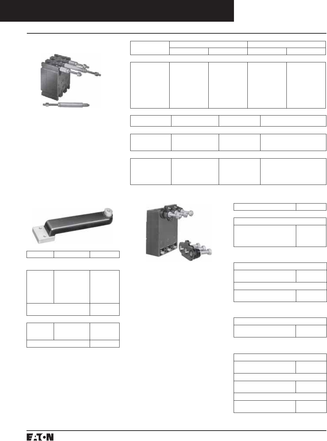
PG.74A.01.T.E
Cutler-Hammer
124 March 1999
Plug-in Adapter Kits
For rear connected applications such
as switchboards. Facilitates ease of
installation and front removal of
breaker. Includes conductor for
mounting on breaker, plug-in
mounting blocks with matching con-
ductor, rear studs and mounting
hardware. Order two mounting
blocks style number when line and
load are required; order one mount-
ing block style number when either
line or load is required.
Molded Case Circuit Breaker
Accessories for Current Limiting Circuit Breakers
Rear Connected Studs➀
For complete stud assembly, order a
stud and appropriate tube based on
thickness of customer’s mounting
panel. A short stud must be assem-
bled adjacent to a long stud to
maintain clearances required by
Underwriters Laboratories, Inc.➁
Two studs are required per pole.
➀Not Underwriters Laboratories, Inc. listed.
➁400 ampere LA studs of the same length
have sufficient clearance; however, cust-
omer connections may make it necessary
to use a short stud adjacent to a long stud.
➂Included at no charge when ordered with
stud.
➃150, 250, 300 and 400 ampere frames only.
➄These plug-in adapter kits are UL listed as
recognized components.
Mounting Panel
Thickness, Inches
Stud Tube➂
Length Style Number Length Style Number
FCL and FB Tri-Pac Breakers
1
11⁄16 - 15⁄16
3⁄8 - 5⁄8
1⁄4 - 5⁄16
Short
Long
Short
Long
Short
Long
Short
Long
451D874G01
451D874G02
451D874G01
451D874G02
451D874G01
451D874G02
451D874G01
451D874G02
11⁄16
37⁄16
13⁄8
33⁄4
111⁄16
41⁄16
2
43⁄8
32B9446H20
32B9446H24
32B9446H21
32B9446H25
32B9446H22
32B9446H26
32B9446H23
32B9446H27
Stud Ampere Rating Diameter, Inches
and Thread
Extension Back of
Breaker, Inches
Stud Style Number
LCL, LA Tri-Pac Breakers
400➃
400➃
400➃
3⁄4 -16
3⁄4 -16
3⁄4 -16
515⁄32
731⁄32
1015⁄32
05B7383G15
05B7383G16
05B7383G17
NB Tri-Pac Breakers
450
450
450
800
800
11⁄8 -12
11⁄8 -12
11⁄8 -12
11⁄4 -12
11⁄4 -12
51⁄2
8
101⁄2
51⁄2
101⁄2
623B222G01
623B222G02
623B222G03
623B375G04
623B375G03
Panelboard Connecting
Staps➀
For connecting line end of breakers
to panelboard bus.
Ampere Rating Connector Type Style Number
Power Panelboards (Convertible)
Tri-Pac FB and FCL Breakers Bus Spacing 31⁄2-inch
50
50
100
100
150
150
Center
Outside
Center
Outside
Center
Outside
1253C72G01
1253C72G02
1253C73G03
1253C73G04
1253C73G01
1253C73G02
3-Pole Mounting Bracket
2-Pole Mounting Bracket
624B600H01
624B600H02
LCL Breakers Bus Spacing 31⁄2-inch
400
400
400
Short
Medium
Long
1275C85G01
1275C85G02
1275C85G03
Mtg. Bracket Kit (1 Req’d) 751B044G01
Instruction Leaflet/FRED Number 13782
Instruction Leaflet/FRED Number 15329
Instruction Leaflet/FRED Number 15073
Description Style Number
FB Tri-Pac and FCL Breakers➄
1 Mounting Block, Line or Load
2-Pole, 100 Ampere
2-Pole, 150 Ampere
3-Pole, 100 Ampere
3-Pole, 150 Ampere
507C036G05
507C036G06
507C036G03
507C036G04
LCL Breakers
2 Mounting Blocks, Line and Load
2-Pole
3-Pole
313C644G25
313C644G26
1 Mounting Block, Line and Load
2-Pole
3-Pole
450D010G15
450D010G16
NB Tri-Pac Breakers➀
1 Mounting Block, Line or Load
NB Tri-Pac, 2 Poles
NB Tri-Pac, 3 Poles
2614D53G03
2614D53G04
Tri-Pac LA Breakers➀
2 Mounting Blocks, Line and Load
2-Pole
3-Pole
313C644G41
313C644G42
1 Mounting Block, Line Only
2-Pole
3-Pole
450D010G17
450D010G19
1 Mounting Block, Load Only
2-Pole
3-Pole
450D010G18
450D010G20
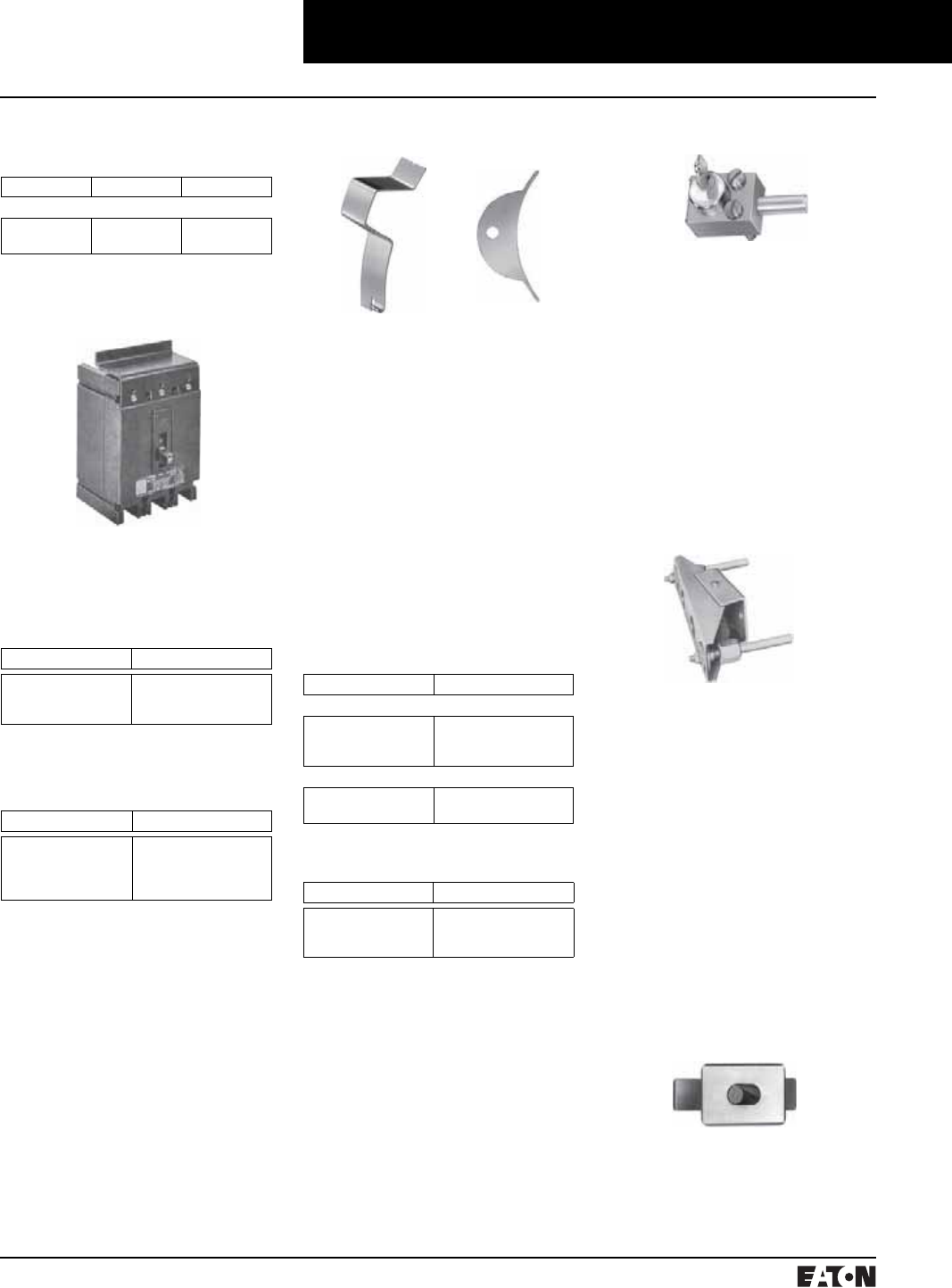
March 1999
PG.74A.01.T.E
Cutler-Hammer 125
Molded Case Circuit Breakers
Accessories for Current Limiting Circuit Breakers
Mechanical Interlocks➁
For mechanically interlocking a pair
of breakers so that only one may be
closed at one time, but both may be
open simultaneously.
Walking Beam Type➁➂➃
Mounts on panel (not included) at
rear of breaker. Standard breaker
spacing: LA Tri-Pac, NB Tri-Pac: 8-1/2
inches center to center; FB Tri-Pac:
4-3/8 inches center to center; PB Tri-
Pac: 12-1/4 inches center to center.
Order as a set of two special factory
drilled breakers and one walking
beam interlock. Specify breaker
type, panel thickness and center-to-
center dimension of breakers.
Sliding Bar Type (Field Mountable)➁➄
Mounts on panel (not included) fit-
ting over front of breakers. Standard
breaker spacing: LA Tri-Pac, NB Tri-
Pac: 8-1/2 inches; FB Tri-Pac: 4-3/16
inches center to center.
Moisture-Fungus-Corrosion
Treatment➁
Treatment can be provided to meet
customer’s specific atmospheric
conditions. Moisture-fungus treat-
ing material used meets JAN-T-152;
treatment meets MIL-V-173a.
Requests and orders should specify
government specifications or condi-
tions to be met.
➂Not UL listed.
➃Not available on drawout breakers.
➄Not available for FCL or LCL breakers.
➅Not available on motor operated breakers.
Kirk Key Interlock➄
Availability: FB, LA, NB, PB Tri-Pacs.
Permits interlocking of two breakers
or one breaker with other devices.
Before breaker can be closed, key
must be inserted and turned in
breaker interlock. Breaker must be
opened before key can be removed.
It can then be inserted in interlock or
other devices to permit their closure.
Requests and orders should com-
pletely outline interlocking scheme,
ultimate user and his address.
Mounting Block for
NB Tri-Pac Breakers➀
Extended Line Terminal
Shields➀
For shielding line side terminal con-
nections. One shield required per
breaker. Order separately when
needed. Sold only in lots of 10,
including hardware.
Base Mounting Hardware
Order separately when needed.
Ampere Rating Number of Poles Style Number
NB Tri-Pac
800
800
2
3
4990D16G04
4990D16G03
Breaker Frame Style Number
FB Tri-Pac, FCL
LA Tri-Pac
NB Tri-Pac
625B229G01
314C420G05
208B996G02
Breaker Frame Style Number
FB Tri-Pac, FCL
LA Tri-Pac
NB Tri-Pac
PB Tri-Pac
21C6782G18
1614613
1091716
624375G22
Handle Locks➀
Non-Padlockable
For prevention of unintentional
operation of breaker. Fits over
breaker handle and may be
removed.
Padlockable
For prevention of unauthorized
operation of breaker. Is non-
removable once installed on
breaker. Meets Underwriters
Laboratories, Inc. and California
Code requirements.
Note: All breakers are trip free and
will trip with handle locks attached.
Cannot be used when handle exten-
sion is used.
Handle Extension
Breaker Frame Style Number
Non-Padlockable
FB Tri-Pac
LA Tri-Pac
NB Tri-Pac
29B2721H01
1720101
1720101
Padlockable
FB Tri-Pac
LA Tri-Pac
765A754G01
373B591G02
Breaker Frame Style Number
LA Tri-Pac
NB Tri-Pac
PB Tri-Pac➁
372B399G01
1251C65G01
315C882G01
➀Not Underwriters Laboratories, Inc. listed.
Insulated base with front removeable bolted
connection.
➁Included with frame
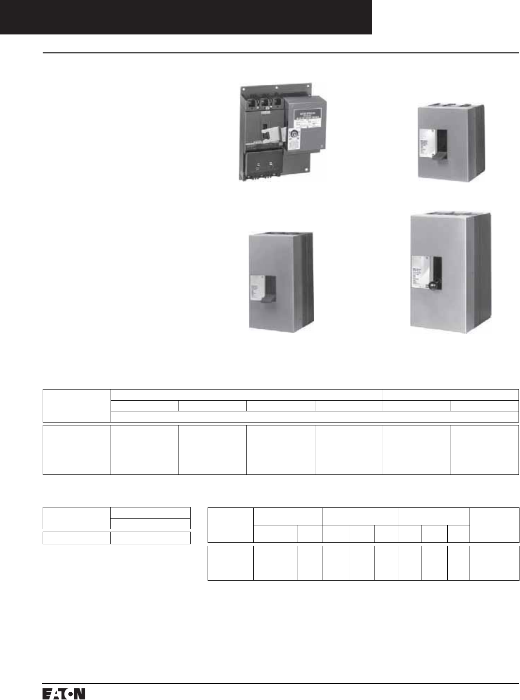
PG.74A.01.T.E
Cutler-Hammer
126 March 1999
Molded Case Circuit Breakers
Accessories for Current Limiting Circuit Breakers
Motor Operators➀
Motor operators provide complete
remote control by means of a push-
button or similar pilot device➁.
Positive switching action is accom-
plished by use of an operating arm
engaging the breaker handle. The
unit is energized momentarily to
actuate the lever arm moving it to
either the “ON” or “OFF” position.
The control is broken by an internal
cutoff switch. Means for emergency
manual operation is provided.
Motor operators are available with
motors rated 120 volts Ac, 208 volts
Ac, and 240 volts Ac.
The 480 volt operators utilize a 120
volt Ac motor in conjunction with a
480/240 to 120 volt dual voltage
transformer. (On LA and larger oper-
ators, the transformer is supplied for
separate mounting by the customer.)
Note: The motor operator is
intended only for infrequent opera-
tion in line with Underwriters Labo-
ratories, Inc. endurance standard for
AB molded case breakers.
Motor Operator Selection
Type
Breaker
Ac Voltage Dc Voltage
120 208 240 480 125 24
Style Number
FCL
LCL
FB Tri-Pac
LA Tri-Pac
NB Tri-Pac
PB Tri-Pac
656D148G15
5664D54G83
656D148G11
2607D97G22
5664D54G65
5661D52G01
656D148G10
5664D54G86
656D148G04
2607D97G25
5664D54G68
5661D52G04
656D148G17
5664D54G84
656D148G13
2607D97G23
5664D54G66
5661D52G02
656D148G17
5664D54G85
656D148G13
2607D97G24
5664D54G67
5661D52G03
–
5664D54G77
–
2607D97G44
5664D54G82
5661D52G17
–
5664D54G88
–
–
–
–
Back Mounting Plates
Type
Breaker
120, 208, 240, 480 Volts Ac
Style Number
FB-P/FCL 1282C01G01
Motor Data
Type
Breaker
Motor Inrush Current,
Ampere (Peak)
Continuous
Current (RMS)
Operating Time,
Open or Close
Type Hp. 120
Volts
208
Volts
240
Volts
120
Volts
208
Volts
240
Volts
FB Tri-Pac
LA Tri-Pac
NB Tri-Pac
PB Tri-Pac
Split Phase
Reversing
Reversing
Reversing
1/75
–
–
–
10
8
11
20
4
5
7
12
5
4
6
11
2.3
–
–
–
1.17
–
–
–
1.65
–
–
–
1.5 Seconds
12 Cycles
12 Cycles
10 Cycles
➀Ac voltage rated operators are UL listed as
recognized components.
➁The pilot device must be maintained contact
type for FB Tri-Pac, FCL, mechanisms;
momentary contact type for all others.
Instruction Leaflet/FRED Number 13148 FCL; 15334 LCL; 13148 FB Tri-Pac; 15533 LA Tri-Pac; 15534 NB Tri-Pac; 14444 PB Tri-Pac
For FB Tri-Pac/FCL Breakers For LA Tri-Pac Breakers
For NB Tri-Pac Breakers For PB Tri-Pac Breakers
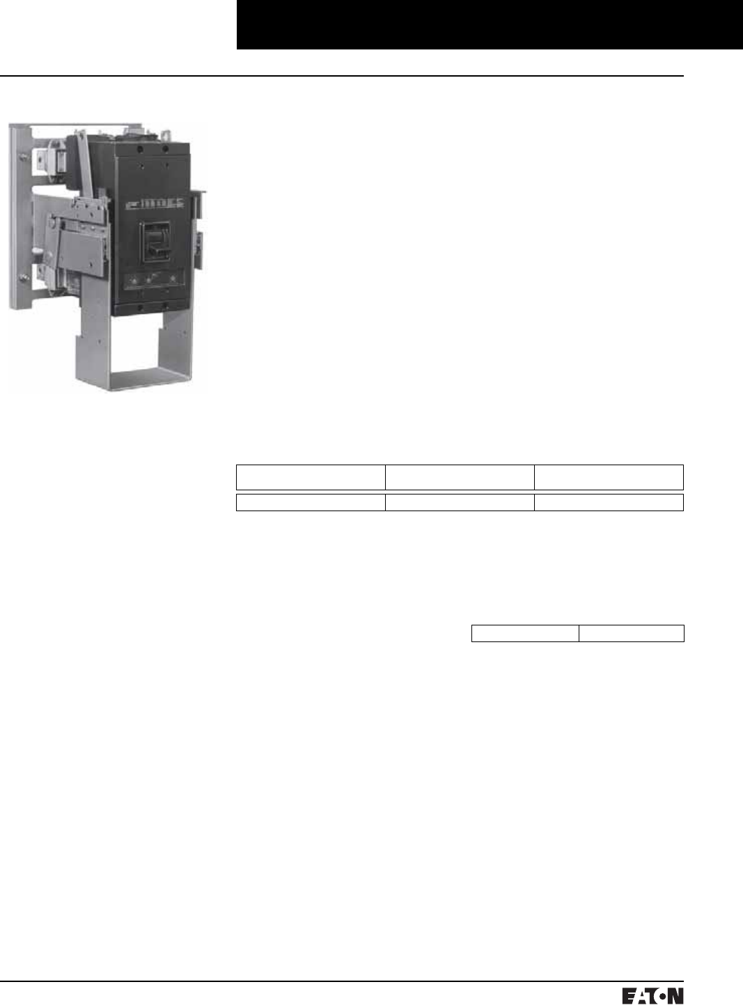
March 1999
PG.74A.01.T.E
Cutler-Hammer 127
Molded Case Circuit Breakers
Accessories for Current Limiting Circuit Breakers
Drawout Frame These drawout frames are for use
with standard 3-pole Cutler-Hammer
molded case circuit breakers. They
consist of two separate parts; sta-
tionary mounting frame and mov-
able carrier frame. Slide rails are
drawer-type, and a screw mecha-
nism is used to engage or withdraw
the movable carrier frame.
The drawout frames have three
positions: connected, test and
disconnected. The frames do not
include a safety tripping interlock,
or secondary contacts. These are
optional items and may be ordered
at additional cost.
Breakers mounted in the drawout
frames can be equipped with stan-
dard breaker accessories including
shunt trip, undervoltage release,
auxiliary switch, alarm switch and
motor operator.
Secondary Contacts
These are used to disconnect auxil-
iary circuits when attachments such
as shunt trip or motor operator are
used. Available in multiples of four
contacts with a maximum of 32 con-
tacts for the NB Tri-Pac. They must
be factory mounted. Order by
description as similar to stationary
or moving frame and specify num-
ber of contacts required.
Selection Data
Breaker Type➀Stationary Mounting Frame
Style Number
Movable Carrier Frame
Style Number
NB Tri-Pac 2603D85G09 2608D34G12
➀Drawout for FB and LA Tri-Pac, FCL, and LCL
Circuit Breakers are not available. PB Tri-Pac
movable is available factory-installed only.
Order by description.
Standard Installation
Order one stationary mounting
frame and one movable carrier
frame.
Order breakers without terminals
or rear connectors.
Order any attachments desired
(shunt trip, undervoltage release,
etc.)
Order secondary contacts as
required:
■A shunt trip, undervoltage release
or alarm switch requires two
contacts;
■A 1A-1B auxiliary switch requires
three contacts;
■A motor operator requires a
maximum of four contacts;
■Others as required.
Racking Crank
A special crank to engage or with-
draw the moving portion of the
drawout. A standard 1/2 inch hex
socket with extension can be used
for this purpose.
Cell Switches Mounted on
Drawout Frames, All Ratings
Up to four switches can be provided.
Order by description.
Each switch provides NO and NC
contact that transfers before reach-
ing the test position when being
withdrawn, and after the test posi-
tion when being racked in.
Style Number 765A767G01

PG.74A.01.T.E
Cutler-Hammer
128 March 1999
Molded Case Circuit Breakers

March 1999
PG.74A.01.T.E
Cutler-Hammer 129
Molded Case Circuit Breakers
Engine Generator Circuit Breakers
General Information
Engine generator molded case circuit
breakers are designed specifically for
application on diesel engine pow-
ered standby generators where high
interrupting circuit breakers are not
required. The JG through NG break-
ers are equipped with a special trip
unit, that includes standard thermal
(overload) protection and special low
magnetic pickup range (FG includes
a fixed thermal/magnetic pickup).
The standard thermal trip unit
provides overload protection for
conductors per the National Electric
Code. The low magnetic pickup
range is approximately two to five
times the continuous rating and
provides closer low level short circuit
protection when applied on genera-
tors that have very low short circuit
capacity. This combination allows
the user to customize the breaker to
the generator output.
Interrupting Capacity Ratings
UL 489 Interrupting Capacity Ratings
Interrupting Capacity (Symmetrical
Amperes)
Volts Ac (50/60 Hz)
240 18,000
480 14,000
600 10,000
IEC 947-2 Interrupting Capacity
Ratings
Interrupting Capacity (Symmetrical
Amperes)
Volts Ac (50/60 Hz)
220, 240 18,000/9,000
380, 415 14,000/7,000
660, 690 10,000/5,000
Standards
Engine generator molded case cir-
cuit breakers are designed to con-
form with the following standards:
■Underwriters Laboratories, Inc.,
Standard UL 489, Molded Case
Circuit Breakers and Circuit
Breaker Enclosures File E7819
■Canadian Standards Association
Standard C22.2 No. 5, Service
Entrance and Branch Circuit
Breakers
■International Electrotechnical
Commission Recommendations
IEC 947-2, Circuit Breakers
Conformance with these standards
satisfies most local and international
codes, assuming user acceptability
and simplified application.
Catalog Numbering System
This information is presented only
as an aid to understanding catalog
numbers. It is not to be used to build
catalog numbers for circuit breakers.
FG breakers include both line and
load side terminals.
JG, KG, LG, and NG breakers with
“W” catalog number suffix do not
include any terminals.
JG, KG, LG, and NG breakers with-
out “W” catalog number suffix
include both line and load terminals.
Contact Cutler-Hammer for addi-
tional ratings and internal/external
accessories.
FG 3 100 W
Frame
FG
JG
KG
LG
NG
Number
of Poles
3
Trip
Amperes
15
20
25
30
35
40
45
50
60
70
80
90
100
125
150
175
200
225
175
200
225
250
300
350
400
450
500
600
700
800
900
1000
1200
Suffix
W: Without Terminals

PG.74A.01.T.E
Cutler-Hammer
130 March 1999
Molded Case Circuit Breakers
Engine Generator Circuit Breakers
Circuit Breakers
➀Breaker continuous current is based on 115%
of the generator full load ampere rating.
➁Based on three-phase generators at 80%
power factor.
➂Without terminals.
Magnetic Pickup
Range
Maximum Generator Rating 60 Hz Engine Generator
Breaker Catalog
Number
240 Vac 480 Vac 600 Vac
kVA➀kW➁kVA➀kW➁kVA➀kW➁
Fixed
Fixed
Fixed
Fixed
5
7
9
11
4
6
7
9
11
14
18
22
9
12
14
17
14
18
23
27
11
14
18
22
FG3015
FG3020
FG3025
FG3030
Fixed
Fixed
Fixed
Fixed
13
14
16
18
10
12
13
14
25
29
32
36
20
23
26
29
32
36
41
45
25
29
32
36
FG3035
FG3040
FG3045
FG3050
Fixed
Fixed
Fixed
Fixed
22
25
29
32
17
20
23
26
43
51
58
65
35
40
46
52
54
63
72
81
43
51
58
65
FG3060
FG3070
FG3080
FG3090
Fixed
Fixed
Fixed
Fixed
Fixed
Fixed
Fixed
36
40
45
54
63
72
81
29
32
36
43
51
58
65
72
79
90
108
126
144
162
58
64
72
87
101
116
130
90
99
113
135
158
181
203
72
79
90
108
126
144
162
FG3100
FG3110
FG3125
FG3150
FG3175
FG3200
FG3225
350-700
350-700
63
72
51
58
126
144
101
116
158
181
126
144
JG3175W➂
JG3175
JG3200W➂
JG3200
350-700
350-700
81
90
65
72
162
181
130
144
203
226
162
181
JG3225W➂
JG3225
JG3250W➂
JG3250
500-1000
500-1000
108
126
87
101
217
253
173
202
271
316
217
253
KG3300W➂
KG3300
KG3350W➂
KG3350
1000-2000
600-2500
144
162
116
130
289
325
231
260
361
406
289
325
KG3400W➂
KG3400
LG3450
LG3450W➂
600-2500
600-2500
181
217
144
173
361
433
289
347
451
542
361
433
LG3500
LG3500W➂
LG3600
LG3600W➂
800-2500
800-2500
253
289
202
231
505
578
404
462
632
722
505
578
NG3700
NG3700W➂
NG3800
NG3800W➂
1600-5000
1600-5000
325
361
260
289
650
722
520
578
812
903
650
722
NG3900
NG3900W➂
NG31000
NG31000W➂
1600-5000 433 347 867 693 1083 867 NG31200
NG31200W➂
The following table lists FG through
NG engine generator breakers with
the maximum generator kVA and kW
rating. Engine generator breakers
are applied at 115% of the generator
full load current rating. The maximum
kW rating is based on three-phase
generators at 80% power factor.
Time/Current Curves, Dimension Sheets, Application Data
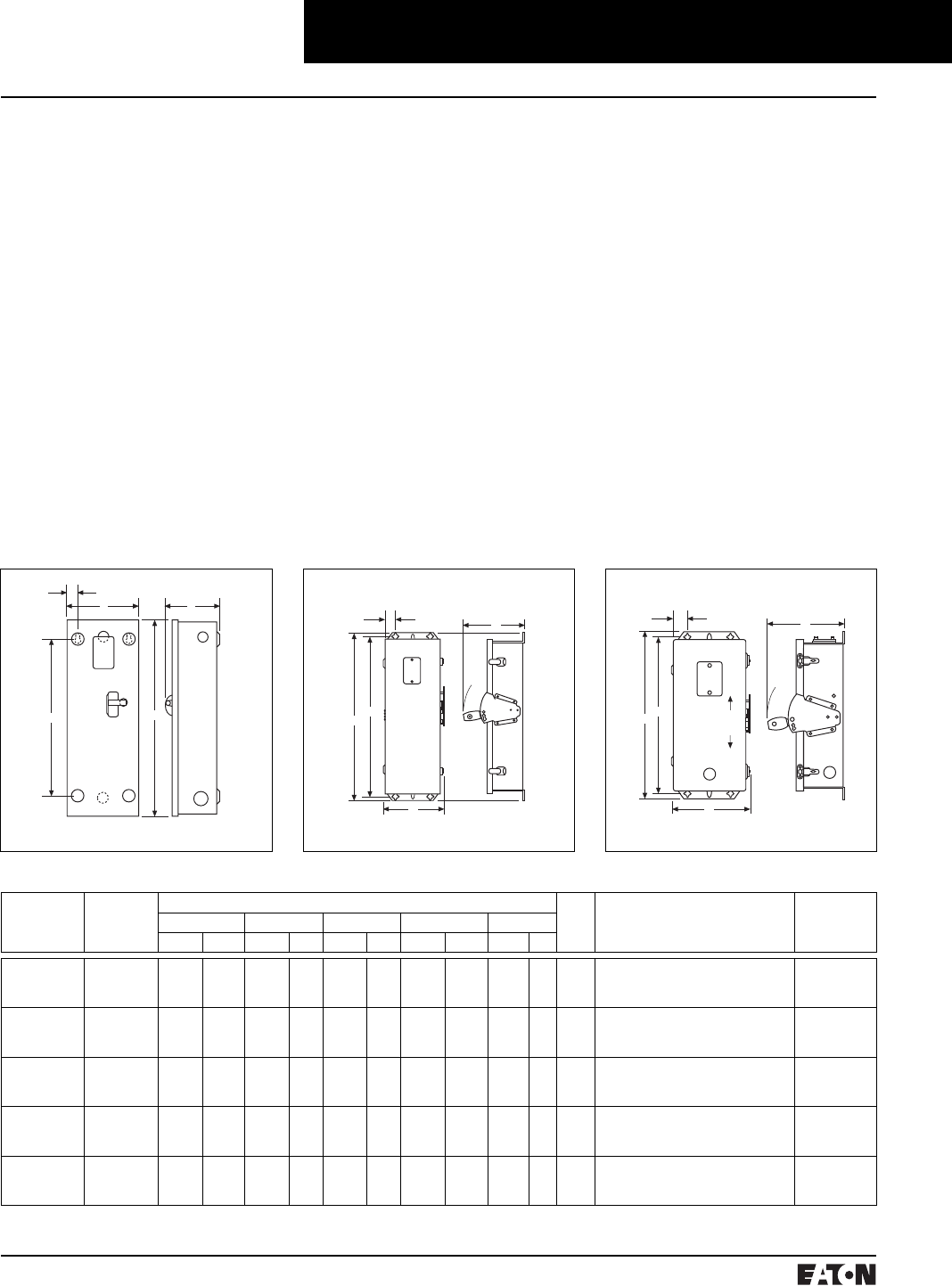
March 1999
PG.74A.01.T.E
Cutler-Hammer 131
Molded Case Circuit Breakers
Engine Generator Circuit Breakers
Enclosures
Enclosure Description
Type 1 General Purpose
■Surface or Flush Mounting
■15-1200 Ampere Range
■600 Volts Ac, 500 Volts Dc
Type 1 enclosed breakers are
designed for use in commercial
buildings, apartment buildings and
other areas where a general purpose
enclosure is applicable. The breaker
is front operable and is capable of
being padlocked in either the On or
Off position. Ratings through 1200
amperes are listed with Underwrit-
ers Laboratories, Inc. as approved
for service entrance application.
Both surface and flush mounted
enclosures are available.
Type 3R Rainproof
Surface Mounting
■Interchangeable Hubs
(Through 400 Amperes)
■15-1200 Ampere Range
■600 Volts Ac, 500 Volts Dc
This general purpose outdoor ser-
vice center employs a circuit breaker
inside a weatherproof sheet steel
breaker enclosure to serve as a main
disconnect and protective device for
feeder circuits. Ratings through 1200
amperes are listed by Underwriters
Laboratories, Inc. as suitable for ser-
vice entrance application.
Type 12 Dustproof
Surface Mounting
■No Knockouts or Other Openings
■15-1200 Ampere Range
■600 Volts Ac, 500 Volts Dc
The Type 12 enclosure is designed
in line with specifications for special
industry application where unusu-
ally severe conditions involving oil,
coolant, dust and other foreign
materials exist in the operating
atmosphere. The handle padlocks in
the Off position and the cover is
interlocked with the handle mecha-
nism to prevent opening the cover
with the circuit breaker in the On
position. Ratings through 1200
amperes are listed by Underwriters
Laboratories, Inc. as suitable for ser-
vice entrance application.
E
DA
C
B
C
ON
OFF
E
AD
B
ON
OFF
EC
AD
B
Enclosure Selection Data
Breaker
Frame
(Amperes)
Enclosure
Type Class
Dimensions App.
Wt.
Lbs.
Conduit Sizes,
Inches
Catalog
Number
ABCDE
Inches mm Inches mm Inches mm Inches mm Inches mm
FG
15-225
Type 1
Type 3R
Type 12
23.25
25.66
25.66
591
652
652
8.41
8.84
8.84
214
225
226
6.28
9.31
9.31
160
237
238
18.75
24.28
24.28
476
617
618
1.20
1.70
1.70
31
43
43
15
19
18
.25, .50, .75, 1, 1.25, 1.50, 2, 2.50
.25, .50, .75, 1, 1.25, 1.50, 2, 2.50
SFDN225
RFDN225
JFDN225
JG
175-250
Type 1
Type 3R
Type 12
34.70
37.50
37.53
881
891
953
10.92
11.56
11.56
227
294
294
7.20
10.22
10.22
183
260
260
30.00
35.77
35.77
762
909
909
1.88
1.94
1.94
48
49
49
31
40
37
.25, .50, 2, 2.50, 3
.25, .50, 2, 2.50, 3
SJDN250
RJDN250
JJDN250
KG
300-400
Type 1
Type 3R
Type 12
38.81
41.69
41.69
986
997
997
11.06
11.75
11.75
281
298
298
10.94
14.06
14.06
278
357
357
34.00
39.90
39.90
869
1014
1015
2.28
1.97
1.97
58
50
50
53
60
53
.25, .50, .75, 1.50, 2, 2.50, 3, 3.50
.25, .50, .75, 2.50, 3, 3.50
SKDN400
RKDN400
JKDN400
LG
450-600
Type 1
Type 3R
Type 12
45.88
48.31
48.31
1165
1227
1227
14.31
14.91
14.91
364
379
379
12.38
15.50
15.50
314
394
394
46.56
46.56
46.56
1183
1183
1183
1.91
1.92
1.92
48
49
49
81
84
81
.25, .50, .75, 3, 3.50, 4
.25, .50, .75, 3, 3.50, 4
SJDN600
RLDN600
JLDN600
NG
700-1200
Type 1
Type 3R
Type 12
61.22
63.59
63.59
1555
1615
1615
21.44
22.00
22.00
545
559
559
15.41
17.63
17.63
391
448
448
61.84
61.84
61.84
1571
1571
1571
1.97
1.97
1.97
50
50
50
178
175
170
SNDN1200
RNDN1200
JNDN1200
Type 3R Rainproof Type 12, 12K DustproofType 1 Surface Mounted
PG.74A.01.T.E
Cutler-Hammer
132 March 1999
Molded Case Circuit Breakers
Engine Generator Circuit Breakers
Accessories
Neutral Kits, Insulated and Groundable
Maximum
Enclosure Rating
(Amperes)
Main Lug Number
Size Cu/Al
Ground Lug
Size Cu/Al
Catalog
Number
100 (1) 14–1/0 (1) 14–1/0 INK100
250 (1) 6–350 kcmil (1) 4–300 kcmil INK250
400 (1) 4–750 kcmil or
(2) 1/0–250 kcmil
(1) 4–300 kcmil INK400
600 (2) 250–500 kcmil (1) 4–300 kcmil INK600
1200 (3) 1/0 to 750 kcmil or
(4) 1/0 to 750 kcmil
(1) #6–250 kcmil INK1200
➀Package of 3 terminals.
Standard Terminals
Breaker
Frame
Maximum
Ampere
Rating
AWG Wire Range Metric Wire
Range mm2Catalog
Number
FG 100 #14-1/0 2.5 -50 3T100FB➀
FG 150 #4-4/0 25 -95 3TA225FD➀
JG 250 #4-350 kcmil 25 -185 TA250KB
KG 350 250-500 kcmil 120 -240 TA350K
KG 400 3/0-250 kcmil (2) 95 -120 3TA400K➀
LG 600 250-500 kcmil (2) 120 -240 TA600LA
NG 700 1-500 kcmil (2) 50 -300 TA700NB1
NG 1000 3/0-400 kcmil (3) 95 -185 TA1000NB1
NG 1200 4/0-500 kcmil (4) 120 -300 TA1200NB1
Internal Accessories
Breaker
Frame
Auxiliary Switch Shunt Trip
1A-1B Catalog
Number
2A-2B Catalog
Number
Rating Catalog
Number
FG A1X1PK A2X1PK 12-24 Vdc SNT1LP03K
JG A1X2PK A2X2PK 12-24 Vdc SNT2P04K
KG A1X3PK A2X3PK 12-24 Vdc SNT3P05K
LG A1X4PK A2X4PK 12-24 Vdc SNT4LP03K
NG A1X5RPK A2X5RPK 12-24 Vdc SNT5LP03K
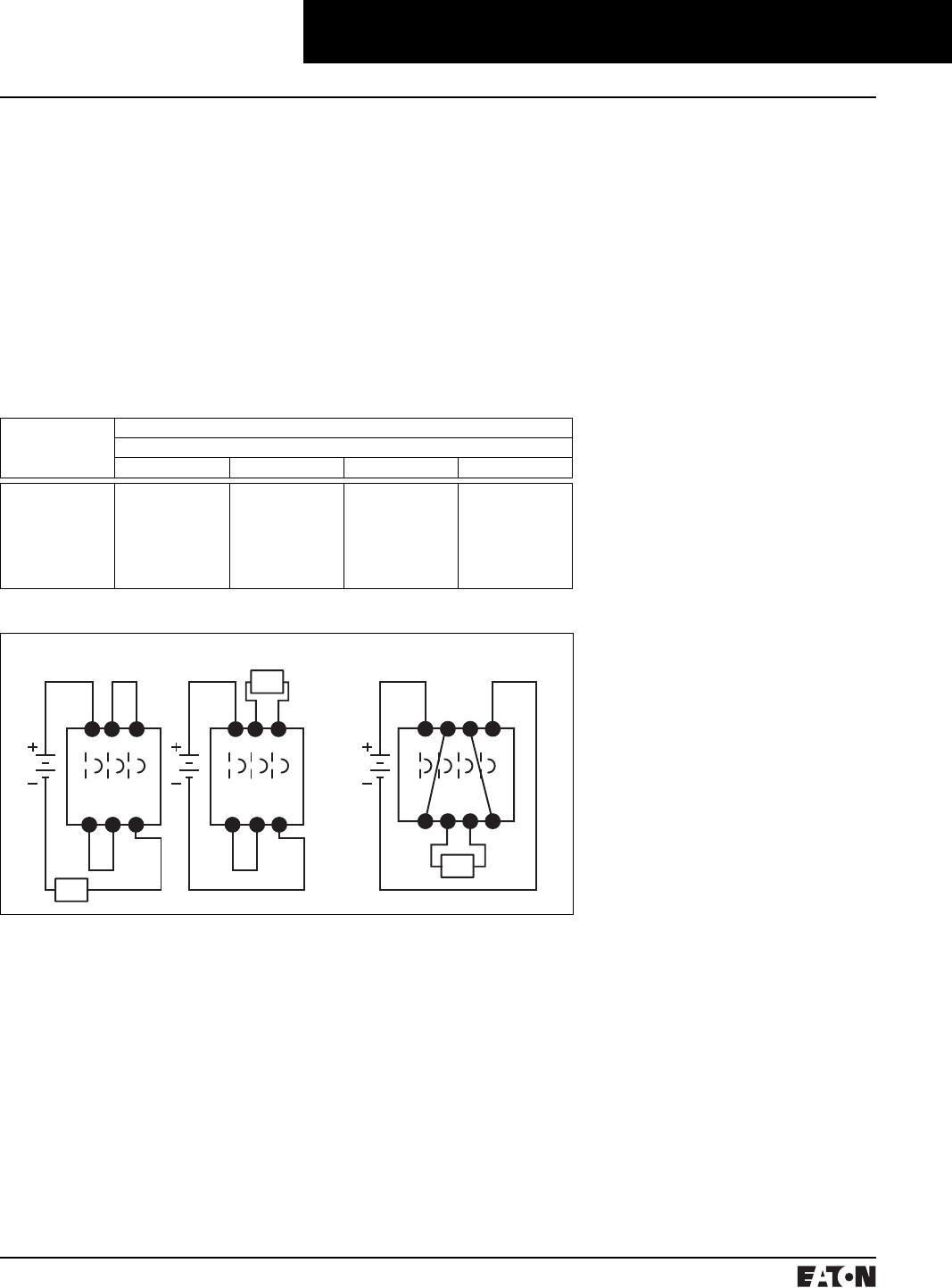
March 1999
PG.74A.01.T.E
Cutler-Hammer 133
Molded Case Circuit Breakers
Series C Circuit Breakers for DC Applications
Interrupting Capacity Ratings
UL489 Interrupting Capacity Ratings
Circuit
Breaker
Type
Interrupting Capacity (Symmetrical kA)
Volts DC➀
125➁250➂600➃750➄
HFDDC
HJDDC
HKDDC
HLDDC
HMDLDC
NBDC
PBDC
42
42
42
42
42
50
75
42
42
42
42
42
50
75
35
35
35
35
35
50
75
20
20
20
20
20
20
20
➀Dc ratings apply to substantially non-
inductive circuits. 8 millisecond time
constant.
➁1-pole in series.
➂2-poles in series.
➃3-poles in series.
➄4-poles in series. Not a UL listed voltage
rating.
➅Use rated cable per NEC Connect to
terminals as per breaker nameplate.
General Information
UL listed dc molded case circuit
breakers for use in general dc cir-
cuits and ungrounded battery supply
circuits of UPS systems providing
continuous, reliable ac power to
computer controlled applications
such as financial transactions and
telecommunications.
For standard interrupting capacity
250 dc molded case circuit breakers.
Refer to Index, Page 1, for appropri-
ate Series C frame size.
The Series C dc breakers listed
below use the same internal and
external accessories as the standard
Series C breaker. NBDC and PBDC
use same internal and external
accessories as standard NB and PB
breakers.
Molded case circuit breakers for
transportation application requiring
750 Vdc are available 15 through
2500 ampere 20 kA interrupting
capacity at 750 Vdc. Breakers require
4 poles in series for 750 Vdc applica-
tion. However, 750V is not a UL rat-
ing. For 750 Vdc application refer to
Cutler-Hammer for ordering infor-
mation. Dimensions are the same
as the standard thermal-magnetic
equivalent.
LOAD
LOAD
3-Poles in Series
LOAD
4-Poles in Series
Series Connection Diagrams for DC Application➅
PG.74A.01.T.E
Cutler-Hammer
134 March 1999
Type HKDDC DC Circuit Breakers
Maximum
Continuous
Ampere Rating
@ 40°C
Circuit Breaker
Frame Only➀
Thermal Magnetic
Trip Unit
Standard
Terminals
Catalog Number
3-Pole High Interrupting Capacity 35 kAIC @ 600 Vac
250
300
350
400
HKDDC3400F KT3250T
KT3300T
KT3350T
KT3400T
TA350K
TA350K
TA350K
3TA400K
300
350
400
450
500
600
HLDDC3600F LT3300T
LT3350T
LT3400T
LT3450T
LT3500T
LT3600T
TA602LD
TA602LD
TA602LD
TA602LD
TA602LD
3TA603LDK
Molded Case Circuit Breakers
Series C Circuit Breakers for DC Applications
Type HMDL DC Circuit Breakers
Maximum
Continuous
Ampere Rating
@ 40°C
Circuit Breaker
Frame Only➀
Thermal Magnetic
Trip Unit
Catalog Number
3-Pole High Interrupting Capacity 35 kAIC @ 600 Vac
300
350
400
450
500
600
700
800
HMDL3800F MT3300T
MT3350T
MT3400T
MT3450T
MT3500T
MT3600T
MT3700T
MT3800T
Type HFDDC DC Circuit Breakers
Maximum
Continuous
Ampere Rating
@ 40°C
Complete Circuit Breaker with Line and Load Terminals
1-Pole 2-Pole 3-Pole
Catalog Number
1, 2, 3-Pole High Interrupting Capacity 35 kAIC @ 600 Vac
15
20
25
30
35
40
45
50
60
70
80
90
100
110
125
150
175
200
225
HFDDC1015L
HFDDC1020L
HFDDC1025L
HFDDC1030L
HFDDC1035L
HFDDC1040L
HFDDC1045L
HFDDC1050L
HFDDC1060L
HFDDC1070L
HFDDC1080L
HFDDC1090L
HFDDC1100L
HFDDC1110L
HFDDC1125L
HFDDC1150L
–
–
–
HFDDC2015L
HFDDC2020L
HFDDC2025L
HFDDC2030L
HFDDC2035L
HFDDC2040L
HFDDC2045L
HFDDC2050L
HFDDC2060L
HFDDC2070L
HFDDC2080L
HFDDC2090L
HFDDC2100L
HFDDC2110L
HFDDC2125L
HFDDC2150L
–
–
–
HFDDC3015L
HFDDC3020L
HFDDC3025L
HFDDC3030L
HFDDC3035L
HFDDC3040L
HFDDC3045L
HFDDC3050L
HFDDC3060L
HFDDC3070L
HFDDC3080L
HFDDC3090L
HFDDC3100L
HFDDC3110L
HFDDC3125L
HFDDC3150L
HFDDC3175L
HFDDC3200L
HFDDC3225L
Type HJDDC DC Circuit Breakers
Maximum
Continuous
Ampere Rating
@ 40°C
Circuit Breaker
Frame Only➀
Thermal Magnetic
Trip Unit
Standard
Terminals
Catalog Number
3-Pole High Interrupting Capacity 35 kAIC @ 600 Vac
70
90
100
125
150
175
200
225
250
HJDDC3250F JT3070T
JT3090T
JT3100T
JT3125T
JT3150T
JT3175T
JT3200T
JT3225T
JT3250T
TA250KB
TA250KB
TA250KB
TA250KB
TA250KB
TA250KB
TA250KB
TA250KB
TA250KB
100
125
150
175
200
225
HKDDC3400F KT3100T
KT3125T
KT3150T
KT3175T
KT3200T
KT3225T
TA300K
TA300K
TA300K
TA300K
TA300K
TA300K
Type PBDC DC Circuit Breakers
Maximum
Continuous
Ampere
Rating
@ 40°C
Complete Circuit
Breaker Factory
Assembled
Without
Terminals➀
Includes Magnetic
Only Trip Unit
Calibrated @ 135%
Standard➁
Terminals
Catalog Number
3-Pole High Interrupting Capacity 75 kAIC @ 600 Vac
1600
2000
2500
PBDC31600W
PBDC32000W
PBDC32500W
Included
Included
Included
BA2000PB
BA2000PB
BA2500PB
➀Complete circuit breaker includes frame, trip
unit, and terminals.
Instruction Leaflet/FRED Number 29C700
Instruction Leaflet/FRED Number 29C701
Type NBDC DC Circuit Breakers
Maximum
Continuous
Ampere
Rating
@ 40°C
Complete Circuit
Breaker Factory
Assembled
Without
Terminals➀
Includes Magnetic
Only Trip Unit
Calibrated @ 135%
Standard
Terminals
Catalog Number
3-Pole High Interrupting Capacity 50 kAIC @ 600 Vac
700
800
900
1000
1200
NBDC3700MW
NBDC3800MW
NBDC3900MW
NBDC31000MW
NBDC31200MW
Included
Included
Included
Included
Included
TA1000NB1
TA1000NB1
TA1000NB1
TA1000NB1
TA1200NB1
Instruction Leaflet/FRED Number 15560
Instruction Leaflet/FRED Number 29C702
Time/Current Curves, Dimension Sheets, Application Data

March 1999
PG.74A.01.T.E
Cutler-Hammer 135
Molded Case Circuit Breakers
Add-on Ground Fault Protection
Type GFM
Type GFM Ground Fault Protection Device
Description
Cutler-Hammer Type GFM devices
are Class 1 Ground Fault Sensing
and Relaying devices designed to
comply with the requirements out-
lined in Underwriters Laboratories,
Inc. Standards for Safety entitled:
Ground Fault Sensing and Relaying
Equipment, UL1053.
Type GFM devices, when properly
installed on a grounded electrical
distribution system, will sense phase
to ground fault currents and cause a
disconnect to open and clear the
fault instantaneously at predeter-
mined current values. These devices
have a maximum voltage rating of
600V, 50/60 Hertz and may be
applied in accordance with Article
230-95 of the National Electrical
Code.
Type GFM Ground Fault Protective
Devices are self-contained combina-
tion sensing and relaying devices
designed primarily for application
on motor circuits and fixed loads
where low-level Ground Fault Equip-
ment Protection is required.
GFM devices are available in two
basic types with each type having
two physical sizes. The two basic
types differ in the type of output
circuit provided. The first type,
designated either GFM2 or GFM4,
employs an internal relay having
S.P.D.T. contacts that will operate a
remote shunt trip device where con-
trol power is available.
The second type, designated either
GFM2A or GFM4A. is completely
solid state with an output SCR circuit
designed to operate a remote, low-
energy, flux transfer shunt trip
mounted in a molded case breaker.
No supplementary control power for
the shunt trip is required.
Size Selection
The proper size selection is a func-
tion of the conductor size of the
equipment being protected. Types
GFM2/GFM2A have approximately a
two-inch window opening. Types
GFM4/GFM4A have approximately a
four-inch window opening.
Rating Selection
The basic Ground Fault Current
Pickup rating of either type GFM
device is 5 amperes, i.e., each unit
when properly installed will initiate a
trip signal to a remote shunt trip
with the presence of a 5 ampere
Ground Fault Current within estab-
lished tolerance limits. Separate
optional rating plugs are available to
alter the pickup rating to a maximum
of 100 amperes.
Control Power
Internal control power is not
required to operate Type GFM
Ground Fault Protective devices. All
internal control power required is
derived from the Ground Fault cur-
rent through the internal current
sensor.
External control power is required to
operate the remote shunt trips used
in conjunction with Type GFM2 and
GFM4 devices.
External control power is not
required with Type GFM2A and
GFM4A devices to operate the spe-
cial remote, low-energy, flux transfer
shunt trips used in molded case cir-
cuit breakers.
Trip Indication/Reset
A combination visual indicator and
reset button is provided on the top
of Type GFM2 and GFM4 devices to
indicate the initiation of a tripping
action to clear a Ground Fault. The
operation of the internal relay will
cause the white button to visibly
raise.
To reset the device, the Indicator/
Reset button must be depressed.
Failure to reset the device will not
allow the associated disconnect
device to be reclosed.
No Indicator/Reset button is pro-
vided on Types GFM2A or GFM4A
since an internal SCR is used in the
output circuit. These devices reset
automatically when the disconnect
opens to clear the Ground Fault.
Application
Type GFM devices may be installed
in Zero Sequence or Ground Return
Sensing methods, Proper Ground
Fault Protection schemes are depen-
dent upon proper system installation
and grounding methods.
Mounting
Each Type GFM device contains a
Ground Fault Sensor which is a spe-
cial current transformer. These are
insulated devices which can be
mounted directly to enclosure sur-
faces. Four tubular rivets secure the
sensor housing. These four (0.200
dia.) mounting holes can be used
to mount the GFM device in either
a vertical or horizontal mounting
position.
Optional mounting brackets as
shown on the next page are available.
These brackets may be mounted on
either the bottom or side depending
upon the installation requirements.
Regardless of the mounting method
used, the top of the device with the
visual indicator/ reset button and
nameplate instructions should be
maintained in a visual position after
installation. GFM devices should be
installed so that all conductors pass-
ing through the conductor window
are physically centered.
Type GFM
Interchangeable
Rating Plug
Reset Indicator Button
Rating
Plug
PG.74A.01.T.E
Cutler-Hammer
136 March 1999
Ordering Information
Order by catalog number or style
number:
1 Basic GFM Unit
1 Rating plug if required
1 Mounting bracket if required
1 Circuit breaker with standard
shunt trip factory installed
(as required), or optionally when
possible, a circuit breaker and field
mountable shunt trip as separate
items.
Rating Plug Installation
To install an optional rating plug to
obtain other than the minimum
5 ampere rating, remove the termi-
nal cover held in position by a single
screw and retention groove. With
the cover removed, insert the rating
plug in the position indicated. The
rating plug is held captive in position
with the addition of the terminal
cover after the wiring is completed.
With the terminal cover in position,
the ampere rating of the rating plug
remains visible.
Output Circuitry
Contact ratings for Type GFM2 and
GFM4 are 10 amperes continuous,
240 volts Ac maximum. Types
GFM2A and GFM4A are intended to
be used only with remote flux trans-
fer shunt trips.
Molded Case Circuit Breakers
Add-on Ground Fault Protection
Type GFM
GFM Optional Rating Plugs
Ampere Rating Catalog Number
10
25
50
50
100
GFMP10
GFMP25
GFMP50
GFMP75
GFMP100
Optional Mounting Brackets
Includes two (2) brackets and mount-
ing hardware
Selection Data
GFM Basic Units
Output Type Approximate Window
Opening, Inches
Basic Ampere Rating
(Plug Omitted)
Operating Time
@ 10 x Ampere Rating
Catalog Number
Unit for Use with Standard Shunt Trip
Relay
Relay
2
4
5
5
0.03 Seconds
0.03 Seconds
GFM2
GFM4
Unit for Use with Flux Transfer Shunt Trips
SCR
SCR
2
4
5
5
0.03 Seconds
0.03 Seconds
GFM2A
GFM4A
GFM
Type
Bracket Kit
Style Number
GFM2/2A
GFM4/4A
750B295G01
750B295G02
Instruction Leaflet/FRED Number 14945
Time/Current Curves, Dimension Sheets, Application Data
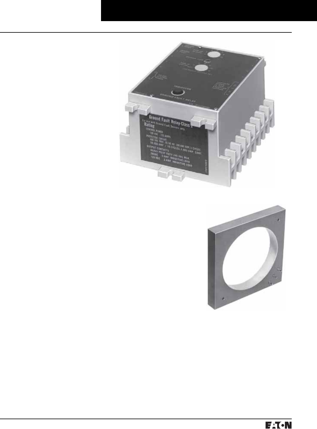
March 1999
PG.74A.01.T.E
Cutler-Hammer 137
Molded Case Circuit Breakers
Add-on Ground Fault Protection
Type GFR
Type GFR
Description
The GFR ground fault relays, current
sensors, test panels and accessory
devices are UL listed by Underwrit-
ers Laboratories, Inc. in accordance
with their standard for Ground Fault
Sensing and Relaying Equipment,
UL 1053, under File E48381.➀
A Type GFR ground fault protection
system, when properly installed on a
grounded electrical system, will
sense phase-to-ground fault cur-
rents. When the level of fault current
is in excess of the pre-selected cur-
rent pickup and time delay settings,
the GFR relay will initiate a trip
action of a disconnect device, which
will open the faulted circuit and clear
the fault.
The GFR devices are UL Class I
devices designed to protect electri-
cal equipment against extensive
damage from arcing ground faults.
A basic Type GFR ground fault pro-
tection system consists of a ground
fault relay➁, a ground fault current
sensor and a disconnect device
equipped with a shunt trip device.
This disconnect device can be a
molded case circuit breaker, a power
circuit breaker, a bolted pressure
switch or other fusible disconnect
device, suitable for application with
UL Class I Ground Fault Sensing and
Relaying equipment.
Additional optional equipment can
be added to the protection system to
meet the requirements of the speci-
fying engineer, including:
■Ground Fault Test Panel
■Ground Fault Warning Indicator
Relay
■Ground Fault Indicating Ammeter
GFR relays are available with zone
selective interlocking circuitry to
interlock several relays within the
same system. This allows the relay
which detects a ground fault to
instantly clear the fault by tripping
the disconnect device. The relay
simultaneously sends a signal to
relay units “upstream” from the
fault to time delay or to block their
operation completely. Current sen-
sors in various designs provide a
range of “window” sizes to accom-
modate standard bus and cable
arrangements.
Shunt trip attachments may be
ordered for field mounting in Cutler-
Hammer molded case circuit break-
ers, or may be ordered factory
installed in the breaker.
Electrical Ratings
GFR Relay
Ground Fault Detection Ranges:
1 to 12, 5 to 60 or 100 to 1200
Amperes
Output contacts:
240 Volt, 50/60 Hz: 3.0 Amperes
120 Volt, 50/60 Hz: 6.0 Amperes
28 Volt Dc: 3.0 Amperes
125 Volt Dc: .5 Amperes
Control power requirements:
120 Volt, 50/60 Hz: .125 Amperes, or
125 Volt Dc (optional)
Typical Current Sensor
GFR Relay
➀Suitable for either surface or semi-flush
mounting.
➁These devices are also listed with CSA under
their file number 43357.
Sensor:
600 Volts, 50/60 Hz maximum
system voltage
PG.74A.01.T.E
Cutler-Hammer
138 March 1999
Molded Case Circuit Breakers
Add-on Ground Fault Protection
Type GFR
Ordering Information
Each installation requires:
1. One relay unit (select trip ampere
as required)
2. One current sensor (select config-
uration required)
GFR Relay
GFR Relay
Types
Catalog Numbers➀
Ground Fault Pickup Amperes
1-12 5-60 100-200
For 120 Volt 50/60 Hz Control
Electrical Reset with Zone Interlocking GRF12EI GFR60EI GFR1200EI
Electrical Reset without Zone Interlocking GRF12E GFR60E GFR1200E
Mechanical Reset with Zone Interlocking GRF12MI GFR60MI GFR1200MI
Mechanical Reset without Zone Interlocking GRF12MI GFR60MI GFR1200MI
For 120 Volt Dc Control
Electrical Reset with Zone Interlocking GRF12EID GFR60EID GFR1200EID
Electrical Reset without Zone Interlocking GRF12ED GFR60ED GFR1200ED
Mechanical Reset with Zone Interlocking GRF12MID GFR60MID GFR1200MID
Mechanical Reset without Zone Interlocking GRF12MID GFR60MID GFR1200MID
Current Sensor
Window Size Style Number
Used with Relays Rated 1-12 Amperes
5.50 In. I.D. 1283C45G01
Used with Relays Rated 5-60 Amperes
2.50 In. I.D.
5.50 In. I.D.
8.25 In. I.D.
7.81 x 11.00 In. Rect.➁
3.31 x 24.94 In. Rect.➁
179C768G01
1256C13G01
179C767G01
1257C88G04
1257C92G03
Used with Relays Rated 100-1200 Amperes
2.50 In. I.D.
5.50 In. I.D.
8.25 In. I.D.
7.81 x 11.00 In. Rect.➁
9.94 x 16.94 In. Rect.➁
9.94 x 23.94 In. Rect.➁
15.94 x 19.94 In. Rect.➁
3.31 x 24.94 In. Rect.➁
6.75 x 29.64 In. Rect.➁
179C768G02
1256C13G02
179C767G02
1257C88G03
1257C90G02
1257C91G02
1257C89G02
1257C92G04
1255C39G03
Instruction Leaflet/FRED Number 15321
➀Suitable for either surface or semi-flush
mounting.
➁One end removable for installation.
➂When a mechanically reset relay is used with
a test panel, both the relay and test panel
must be reset following either a simulated
ground fault test or actual ground fault.
➃Not UL listed.
3. One circuit breaker or disconnect
device with shunt trip, or a shunt
trip attachment for mounting in
existing breaker.
4. Test panel. (Optional)
Accessories
Test Panel (120 Volts Ac)➂
Used to test the ground fault system,
to give an indication the relay has
tripped the breaker, and to reset the
relay after tripping➃. These functions
may be separately mounted pilot
devices.
Ground Fault Warning Indicator
This is an accessory item for use with
GFR Relays with interlocking cir-
cuitry. At approximately 30-50% of
the Relay pickup setting, the indica-
tor switches separate 120 volt Ac
control power to a lamp or relay, (not
included) to give an indication of a
ground fault. The indicator is rated
110/120 volts Ac 50/60 Hz
for a maximum indicator load of
.5 amperes.
Indicating Ammeter➃
The optional indicating ammeter. It
connects to the sensor terminals,
through a momentary contact
pushbutton, and will indicate (in
amperes) any ground fault current
flowing through the sensor. Kit
includes the ammeter and pushbutton.
Shunt Trip Attachments
Use 120 volt Ac shunt trips.
Face Plate
Recommended when these relays
are semi-flush mounted, to close the
door cutout opening.
Optional Test Panel
Control Test Catalog Number
120V 50/60 Hz 120V 50/60 Hz GFRTP
125V Dc 120V 50/60 Hz GFRTPD
Ground Fault Warning
Indicator
Style Number
Manual Reset 1234C67G01
Self-Resetting 1234C67G02
GFR System
Used with
Kit Style
Number
1-12 Ampere
5-60 Ampere
100-1200 Ampere
752B820G01
752B820G02
752B820G03
Description Style Number
Face Plate 752B410G01
Time/Current Curves, Dimension Sheets, Application Data
March 1999
PG.74A.01.T.E
Cutler-Hammer 139
Molded Case Circuit Breakers
Series C Internal Accessories
Alarm Switch
Make
Break
Alarm Switch (RH only)➀
Electrical Rating Contact
Arrangement
Style
Number➁➂➃
Factory
Suffix
Volts Frequency Amperes
Alarm Switch
240 50/60 Hz 6 1 Make/ 1 Break 1288C75G03 B3
Alarm Switch Auxiliary Switches Combination
240 50/60 Hz 6 1 Make/ 1 Break
and 1a/1b
1288C76G09 B13
General Information
For remote indication of automatic
trip operation. Does not function
with manual switching; however, it
will operate when either a shunt trip
or undervoltage release is operated.
➀F-Frame circuit breakers are factory sealed.
Underwriters Laboratories, Inc., requires
that internal accessories be installed at
the factory. Internal accessories are UL listed
for factory installation under E7819. Where
local codes and standards permit and UL
listing is not required, internal accessories
can be field installed. Accessory installation
should be done before the circuit breaker is
mounted and connected.
➁Includes 24-inch external pigtail leads,18
AWG (16-.010).
➂A maximum of two internal accessories may
be mounted in a three-pole circuit breaker.
Instruction Leaflet/FRED Number 15552
Alarm Switch
F-Frame
Electrical Rating Data➄➅
Maximum
Voltage
Frequency Maximum
Current
Amperes
Dielectric
Withstand
Voltage
Multi-Pole Circuit Breakers
600
125
250
50/60 Hz
Dc
Dc
6
0.50➆
0.25➆
2500
2200
2200
Single-Pole Circuit Breakers
125/250
28
28
50/60 Hz
Dc
Dc
6➆
3➆
5➇
2000
2000
2000
Alarm Switch➀
Number of
Contacts
(Make and
Break)
Mounting
Location
(Pole)
Factory Mounted Field Mounted
Connection Type and Location Field Installation Kits➈
18-Inch Pigtail Leads Terminal
Block
Pigtail
Leads
Terminal
Block
Same
Side
Rear➉ Opposite
Side
Same
Side
Suffix Number Catalog Number
1 Left
Right
B01
B05
B02
B06
B03
B07
B04
B08
A1L1LPK
A1L1RPK
A1L1LTK
A1L1RTK
2 Left
Right
B09
B12
B10
B13
–
–
B11
B14
A2L1LPK
A2L1RPK
A2L1LTK
A2L1RTK
1 (Make
Only)
Single
Pole
B15–––––
Instruction Leaflet/FRED Number 29C180
A “make” contact closes and a
“break” contact opens when the
alarm/lockout switch operates. The
switch automatically resets when
the circuit breaker is reset.
Ordering Information
G-Frame
➃Suitable for mounting in right pole only of
2- or 3-pole breaker.
➄Endurance: 6000 electrical operations plus
4000 mechanical operations.
➅Endurance: 6000 electrical operations plus
2000 mechanical operations.
➆Non-inductive load.
➇Inductive (L/R = 0.026).
➈Not listed with Underwriters Laboratories,
Inc., for field installation.
➉Standard pigtail lead exit location.
Standard mounting location.
Factory installation only. Leads exit load end
of circuit breaker.
PG.74A.01.T.E
Cutler-Hammer
140 March 1999
Molded Case Circuit Breakers
Series C Internal Accessories
Alarm Switch
➀Endurance: 6000 electrical operations plus
2000 mechanical operations.
➁Pigtail wire size: No. 18 AWG (0.82 mm2).
➂Non-inductive load.
➃Listed with Underwriters Laboratories, Inc.,
for field installation on interchangeable trip
unit breakers under E64983.
➄Standard mounting location.
➅Standard mounting location – leads exit rear
of breaker.
➆Not for use on 4-pole circuit breakers.
➇Endurance – 5,000 electrical operations plus
1000 mechanical operations.
J-Frame
Electrical Rating Data➀➁
Maximum
Voltage
Frequency Maximum
Current
Amperes
Dielectric
Withstand
Voltage
600
125
250
50/60 Hz
Dc
Dc
6
0.50➂
0.25➂
2500
Alarm Switch
Number of
Contacts
(Make and
Break)
Mounting
Location
(Pole)
Factory Mounted Field Mounted
Connection Type and Location Field Installation Kits➃
18-Inch Pigtail Leads Terminal
Block
Pigtail
Leads
Terminal
Block
Same
Side
Rear➄ Opposite
Side
Same
Side
Suffix Number Catalog Number
1 Left➅
Right
B01
B05
B02
B06
B03
B07
B04
B08
A1L2LPK
A1L2RPK
A1L2LTK
A1L2RTK➆
Instruction Leaflet/FRED Number 29C181
Electrical Rating Data➁➇
Maximum
Voltage
Frequency Maximum
Current
Amperes
Dielectric
Withstand
Voltage
600
125
250
50/60 Hz
Dc
Dc
6
0.50➂
0.25➂
2500
K-Frame
Alarm Switch
Number of
Sets of
Contacts
(1M and 1B)
Mounting
Location
(Pole)
Factory Mounted Field Mounted
Connection Type and Location Field Installation Kits➃
18-Inch Pigtail Leads Terminal
Block
Pigtail
Leads
Terminal
Block
Same
Side
Rear➄ Opposite
Side
Same
Side
Suffix Number Catalog Number
1 Left➅
Right
B01
B05
B02
B06
B03
B07
B04
B08
A1L3LPK
A1L3RPK
A1L3LTK
A1L3RTK
2 Left➅
Right
B09
B12
B10
B13
–
–
B11
B14
A2L3LPK
A2L3RPK
A2L3LTK
A2L3RTK
L- and M-Frames
Alarm Switch
Number of
Sets of
Contacts
(1M and 1B)
Mounting
Location
(Pole)
Factory Mounted Field Mounted
Connection Type and Location Field Installation Kits➃
18-Inch Pigtail Leads Terminal
Block
Pigtail
Leads
Terminal
Block
Same
Side
Rear➄ Opposite
Side
Same
Side
Suffix Number Catalog Number
1 Left➅
Right
B01
B05
B02
B06
B03
B07
B04
B08
A1L4LPK
A1L4RPK
A1L4LTK
A1L4RTK
2 Left➅
Right
B09
B12
B10
B13
–
–
B11
B14
A2L4LPK
A2L4RPK
A2L4LTK
A2L4RTK
Electrical Rating Data➁➇
Maximum
Voltage
Frequency Maximum
Current
Amperes
Dielectric
Withstand
Voltage
600
125
250
50/60 Hz
Dc
Dc
6
0.50➂
0.25➂
2500
Instruction Leaflet/FRED Number 29C183
Instruction Leaflet/FRED Number 29C182

March 1999
PG.74A.01.T.E
Cutler-Hammer 141
Molded Case Circuit Breakers
Series C Internal Accessories
Alarm Switch
N-Frame
Electrical Rating Data➀
Maximum
Voltage
Frequency Maximum
Current
Amperes
Dielectric
Withstand
Voltage
600
125
250
50/60 Hz
Dc
Dc
6
0.50➁
0.25➁
2500
Alarm Switch
Number of
Sets of
Contacts
(Make and
Break)
Mounting
Location
(Pole)
Factory Mounted Field Mounted
Connection Type and Location Field Installation Kits➂
18-Inch Pigtail Leads Terminal
Block
Pigtail
Leads
Terminal
Block
Same
Side
Rear➃ Opposite
Side
Same
Side
Suffix Number Catalog Number
1 Left
Right➃
B01
B05
B02
B06
B03
B07
B04
B08
A1L5LPK
A1L5RPK
A1L5LTK
A1L5RTK
2 Left
Right➃
B09
B12
B10
B13
–
–
B11
B14
A2L5LPK
A2L5RPK
A2L5LTK
A2L5RTK
Instruction Leaflet/FRED Number 29C184
R-Frame
Electrical Rating Data➄➅
Maximum
Voltage
Frequency Maximum
Current Amperes
600
125
250
50/60 Hz
Dc
Dc
6
0.50➁
0.25➁
Alarm Switch (RH only)
Number of
Contacts
(Make and Break)
Factory Mounted Field Mounted
Connection Type and Location Field Installation Kits➂
18-Inch Pigtail Leads Pigtail Leads
Suffix Number➆ Catalog Number➆
1 B05 A1L6RPK
2 B12 A2L6RPK
Instruction Leaflet/FRED Number 29C185
➀Endurance – 3000 electrical operations plus
1000 mechanical operations.
➁Non-inductive load.
➂Listed with Underwriters Laboratories, Inc.
for field installation under E64983.
➃Standard mounting location – leads exit rear
of breaker.
➄Endurance: 500 electrical operations plus
2500 mechanical operations.
➅Pigtail wire size: No. 18 AWG (0.82 mm2).
Leads are red, black and blue.
➆A maximum of three ASL plug-in modules
may be installed in a circuit breaker.
PG.74A.01.T.E
Cutler-Hammer
142 March 1999
Molded Case Circuit Breakers
Series C Internal Accessories
Auxiliary Switch
a
b
Auxiliary Switch General Information
The auxiliary switch provides circuit
breaker contact status information
by monitoring the position of the
molded cross bar which contains the
moving contact arms. The auxiliary
switch is used for remote indication
and interlock system verification,
and consists of one or two SPDT
switches housed in a plug-in mod-
ule. Each SPDT switch has one “a”
and one “b” contact. When the cir-
cuit breaker contacts are open, the
“a” contact is open and the “b”
contact is closed.
Ordering Information
G-Frame Auxiliary (RH only)
Electrical Ratings Contact
Arrangement
Style
Number➀➁➂
Factory
Suffix
Volts Frequency Amperes
240
240
50/60 Hz
50/60 Hz
6
6
1a/1b
2a/2b
1288C74G03
1288C73G03
A3
A6
Instruction Leaflet/FRED Number 15551
F-Frame
Electrical Rating Data➃➄
Maximum
Voltage
Frequency Maximum
Current
Amperes
Dielectric
Withstand
Voltage
125➅
600
125
250
50/60 Hz
50/60 Hz
Dc
Dc
1
6
0.50➆
0.25➆
2500
2500
2200
2200
Auxiliary Switch
Number of
Contacts
a and b
Mounting
Location
(Pole)
Factory Mounted Field Mounted
Connection Type and Location Field Installation Kits➇
18-Inch Pigtail Leads Terminal
Block
Pigtail
Leads
Terminal
Block
Same
Side
Rear➈ Opposite
Side
Same
Side
Suffix Number Catalog Number
1 Left➄
Right or
Neutral
A01
A15➉
A05
A18➉
A02
A16➉
A06
A19➉
A03
A17➉
A07
A20➉
A04
–
A08
–
A1X1PK
E1X1PK
A1X1PK
–
A1X1LTK
–
A1X1RTK
–
2 Left➄
Right or
Neutral
A09
A21➉
A12
A23➉
A10
A22➉
A13
A24➉
–
–
–
–
A11
–
A14
–
A2X1LPK
E2X1LPK
A2X1RPK
E2X1RPK
A2X1LTK
–
A2X1RTK
–
Instruction Leaflet/FRED Number 29C120
J-Frame
Electrical Rating Data➃➄
Maximum
Voltage
Frequency Maximum
Current
Amperes
Dielectric
Withstand
Voltage
600
125
250
50/60 Hz
Dc
Dc
6
0.50➆
0.25➆
2500
Auxiliary Switch
Number of
Sets of
Contacts
(1a and 1b)
Mounting
Location
(Pole)
Factory Mounted Field Mounted
Connection Type and Location Field Installation Kits
18-Inch Pigtail Leads Terminal
Block
Pigtail
Leads
Terminal
Block
Same
Side
Rear Opposite
Side
Same
Side
Suffix Number Catalog Number
1 Left
Right
A01
A05
A02
A06
A03
A07
A04
A08
A1X2PK
A1X2PK
A1X2LTK
A1X2RTK
2 Left
Right
A09
A12
A10
A13
–
–
A11
A14
A2X2PK
A2X2PK
A2X2LTK
A2X2RTK
Instruction Leaflet/FRED Number 29C121
➀Includes 24-inch external pigtail leads,
#18 AWG (16-.010).
➁A maximum of two internal accessories may
be mounted in a three-pole circuit breaker.
➂Suitable for mounting in right pole only of
2- or 3-pole breaker.
➃Endurance: 6000 electrical operations plus
4000 mechanical operations.
➄Pigtail wire size: No. 18 AWG (0.82 mm2).
➅For use in electronic circuit of 100 micro-
amperes and 15 Vdc minimum.
➆Non-inductive load.
➇Not listed with Underwriters Laboratories,
Inc., for field installation.
➈Standard pigtail lead exit location.
➉125-volt (Max.), 50/60 Hz switch for use in
electronic circuit of 100 micro-amp and 15
Vdc minimum.
Listed with Underwriters Laboratories, Inc.
for field installation or interchangeable trip
unit breakers under E64983.
Standard mounting location – leads exit rear
of breaker.
Not for use on 4-pole circuit breakers.

March 1999
PG.74A.01.T.E
Cutler-Hammer 143
Molded Case Circuit Breakers
Series C Internal Accessories
Auxiliary Switch
Electrical Rating Data➀➁
Maximum
Voltage
Frequency Maximum
Current
Amperes
Dielectric
Withstand
Voltage
600
125
250
50/60 Hz
Dc
Dc
6
0.50➂
0.25➂
2500
K-Frame
Auxiliary Switch
Number of
Sets of
Contacts
(1M and 1B)
Mounting
Location
(Pole)
Factory Mounted Field Mounted
Connection Type and Location Field Installation Kits➃
18-Inch Pigtail Leads Terminal
Block
Pigtail
Leads
Terminal
Block
Same
Side
Rear➄ Opposite
Side
Same
Side
Suffix Number Catalog Number
1 Left
Right➄
A01
A05
A02
A06
A03
A07
A04
A08
A1X3PK
A1X3PK
A1X3LTK
A1X3RTK➅
2 Left
Right➄
A09
A12
A10
A13
–
–
A11
A14
A2X3PK
A2X3PK
A2X3LTK
A2X3RTK➅
3 Left
Right
A18
A17
–
–
–
–
A15
A16
A3X3LPK
A3X3RPK
A3X3LTK
A3X3RTK➅
Instruction Leaflet/FRED Number 29C122
L- and M-Frames
Electrical Rating Data➁
Maximum
Voltage
Frequency Maximum
Current
Amperes
Dielectric
Withstand
Voltage
600
125
250
50/60 Hz
Dc
Dc
6
0.50➂
0.25➂
2500
Auxiliary Switch
Number of
Sets of
Contacts
(1a and 1b)
Mounting
Location
(Pole)
Factory Mounted Field Mounted
Connection Type and Location Field Installation Kits➃
18-Inch Pigtail Leads Terminal
Block
Pigtail
Leads
Terminal
Block
Same
Side
Rear➄ Opposite
Side
Same
Side
Suffix Number Catalog Number
1 Left
Right➄
A01
A05
A02
A06
A03
A07
A04
A08
A1X4PK
A1X4PK
A1X4LTK
A1X4RTK➅
2 Left
Right➄
A09
A12
A10
A13
–
–
A11
A14
A2X4PK
A2X4PK
A2X4LTK
A2X4RTK➅
3 Left
Right➄
A18
A17
–
–
–
–
A15
A16
A3X4PK
A3X4PK
A3X4LTK
A3X4RTK➅
Instruction Leaflet/FRED Number 29C123
➀Endurance – 5000 electrical operations plus
1000 mechanical operations.
➁Pigtail wire size – No. 18 AWG (0.82 mm2).
➂Non-inductive load.
➃Listed with Underwriters Laboratories, Inc.
for field installation under E64983.
➄Standard mounting location – leads exit rear
of breaker.
➅Not for use on 4-pole circuit breaker.
PG.74A.01.T.E
Cutler-Hammer
144 March 1999
Molded Case Circuit Breakers
Series C Internal Accessories
Auxiliary Switch
➀Endurance – 3000 electrical operations plus
1000 mechanical operations.
➁Pigtail wire size – No. 18 AWG (0.82 mm2).
➂Non-inductive load.
➃Listed with Underwriters Laboratories, Inc.
for field installation under E64983.
➄Standard mounting location – leads exit rear
of breaker.
➅Not for use on 4-pole circuit breaker.
➆Endurance: 500 electrical operations plus
2500 mechanical operations.
➇Pigtail wire size: No. 18 AWG (0.82 mm2).
Leads are red, black and blue.
➈A maximum of two auxiliary switches (any
combination of 2a/2b or 4a/4b plug-in mod-
ules may be installed in a circuit breaker.
N-Frame
Electrical Rating Data➀➁
Maximum
Voltage
Frequency Maximum
Current
Amperes
Dielectric
Withstand
Voltage
600
125
250
50/60 Hz
Dc
Dc
6
0.50➂
0.25➂
2500
Auxiliary Switch
Number of
Sets of
Contacts
(1A and 1B)
Mounting
Location
(Pole)
Factory Mounted Field Mounted
Connection Type and Location Field Installation Kits➃
18-Inch Pigtail Leads Terminal
Block
Pigtail
Leads
Terminal
Block
Same
Side
Rear➄ Opposite
Side
Same
Side
Suffix Number Catalog Number
1 Left
Right➄
A01
A05
A02
A06
A03
A07
A04
A08
A1X5LPK
A1X5RPK
A1X5LTK
A1X5RTK➅
2 Left
Right➄
A09
A12
A10
A13
–
–
A11
A14
A2X5LPK
A2X5RPK
A2X5LTK
A2X5RTK➅
3 Left
Right➄
A18
A17
–
–
–
–
A15
A16
A3X5LPK
A3X5RPK
A3X5LTK
A3X5RTK➅
Instruction Leaflet/FRED Number 29C124
R-Frame
Electrical Rating Data➆➇
Maximum
Voltage
Frequency Maximum
Current Amperes
600
125
250
50/60 Hz
Dc
Dc
6
0.50➂
0.25➂
Auxiliary Switch (RH only)
Number of
Contacts
(Make and Break)
Factory Mounted Field Mounted
Connection Type and Location Field Installation Kits➃
18-Inch Pigtail Leads Pigtail Leads
Suffix Number➈ Catalog Number➈
2 A12 A2X6RPK
4 A19 A4X6RPK
Instruction Leaflet/FRED Number 29C125

March 1999
PG.74A.01.T.E
Cutler-Hammer 145
Molded Case Circuit Breakers
Series C Internal Accessories
Auxiliary Switch and Alarm Switch Combination
a
b
Auxiliary Switch and Alarm Switch Combination
Auxiliary Switch and Alarm Switch Combination
Mounting
Location
(Pole)
Factory Mounted Field Mounted
Connection Type and Location Field Installation Kits➃
18-Inch Pigtail Leads Terminal Block Pigtail
Leads
Terminal
Block
Same Side Rear⑤ Same Side
Suffix Number Catalog Number
Left➄
Right
C01
C04
C02
C05
C03
C06
AAL1LPK
AAL1RPK
AAL1LTK
AAL1RTK➅
Instruction Leaflet/FRED Number 29C180
Ordering Information
F-Frame
Electrical Rating Data➀➁
Maximum
Voltage
Frequency Maximum
Current
Amperes
Dielectric
Withstand
Voltage
125
600
125
250
50/60 Hz
50/60 Hz
Dc
Dc
1
6
0.50➂
0.25➂
2500
2500
2200
2200
General Information
Each catalog number listed in the
following table includes one auxil-
iary switch and one alarm switch.
In an auxiliary switch ASL switch
combination, the auxiliary switch is
always mounted on the side of the
plug-in module next to the center
pole of the circuit breaker.
Auxiliary Switch and Alarm Switch Combination
Number of
Sets of
Contacts
(1a and 1b
and
1M and 1B)
Mounting
Location
(Pole)
Factory Mounted Field Mounted
Connection Type and Location Field Installation Kits➇
18-Inch Pigtail Leads Terminal
Block
Pigtail
Leads
Terminal
Block
Same
Side
Rear➈ Opposite
Side
Same
Side
Suffix Number Catalog Number
1 Left
Right➈
C01
C04
C02
C05
–
–
C03
C06
AAL2LPK
AAL2RPK
AAL2LTK
AAL2RTK➅
J-Frame
Electrical Rating Data➆➁
Maximum
Voltage
Frequency Maximum
Current
Amperes
Dielectric
Withstand
Voltage
600
125
250
50/60 Hz
Dc
Dc
6
0.50➂
0.25➂
2500
Instruction Leaflet/FRED Number 29C181
Auxiliary Switch and Alarm Switch Combination
Number of
Sets of
Contacts
(1a and 1b
and
1M and 1B)
Mounting
Location
(Pole)
Factory Mounted Field Mounted
Connection Type and Location Field Installation Kits➇
18-Inch Pigtail Leads Terminal
Block
Pigtail
Leads
Terminal
Block
Same
Side
Rear➈ Opposite
Side
Same
Side
Suffix Number Catalog Number
1 Left
Right➈
C01
C04
C02
C05
–
–
C03
C06
AAL3LPK
AAL3RPK
AAL3LTK
AAL3RTK
Instruction Leaflet/FRED Number 29C182
Electrical Rating Data➁
Maximum
Voltage
Frequency Maximum
Current
Amperes
Dielectric
Withstand
Voltage
600
125
250
50/60 Hz
Dc
Dc
6
0.50➂
0.25➂
2500
K-Frame
➀Endurance: 6000 electrical operations plus
4000 mechanical operations.
➁Pigtail wire size: No. 18 AWG (0.82 mm2).
➂Non-inductive load.
➃Not listed with Underwriters Laboratories,
Inc., for field installation.
➄Standard mounting location.
➅Not for use on 4-pole circuit breakers.
➆Endurance – 6000 electrical operations plus
2000 mechanical operations.
➇Listed with Underwriters Laboratories, Inc.
for field installation or interchangeable trip
unit breakers under E64983.
➈Standard mounting location – leads exit rear
of breaker.
Endurance – 5000 electrical operations plus
1000 mechanical operations.

PG.74A.01.T.E
Cutler-Hammer
146 March 1999
Molded Case Circuit Breakers
Series C Internal Accessories
Auxiliary Switch and Alarm Switch Combination
Auxiliary Switch and Alarm Switch Combination
Number of
Sets of
Contacts
Mounting
Location
(Pole)
Factory Mounted Field Mounted
Connection Type and Location Field Installation Kits➃
18-Inch Pigtail Leads Terminal
Block
Pigtail
Leads
Terminal
Block
Same
Side
Rear➄ Opposite
Side
Same
Side
Suffix Number Catalog Number
1A, 1B and
1 Make/
1 Break
Left
Right➄
C01
C04
C02
C05
–
–
C03
C06
AA114LPK
AA114RPK
AA114LTK
AA114RTK➅
2A, 2B and
1 Make/
1 Break
Left
Right➄
C07
C10
C08
C11
–
–
C12
C13
AA214LPK
AA214RPK
AA214LTK
AA214RTK➅
3A, 3B and
1 Make/
1 Break
Left
Right➄
C14
C15
–
–
–
–
–
–
AA314LPK
AA314RPK
–
–
L- and M-Frames
Electrical Rating Data➀➁
Maximum
Voltage
Frequency Maximum
Current
Amperes
Dielectric
Withstand
Voltage
600
125
250
50/60 Hz
Dc
Dc
6
0.50➂
0.25➂
2500
Instruction Leaflet/FRED Number 29C183
➀Endurance – 5000 electrical operations plus
1000 mechanical operations.
➁Pigtail wire size – No. 18 AWG (0.82 mm2).
➂Non-inductive load.
➃Listed with Underwriters Laboratories, Inc.
for field installation under E64983.
➄Standard mounting location – leads exit rear
of breaker.
➅Not for use on 4-pole circuit breaker.
➆Endurance – 3000 electrical operations plus
1000 mechanical operations.
N-Frame
Auxiliary Switch and Alarm Switch Combination
Number of
Sets of
Contacts
Mounting
Location
(Pole)
Factory Mounted Field Mounted
Connection Type and Location Field Installation Kits➃
18-Inch Pigtail Leads Terminal
Block
Pigtail
Leads
Terminal
Block
Same
Side
Rear➄ Opposite
Side
Same
Side
Suffix Number Catalog Number
1A, 1B and
1 Make/
1 Break
Left
Right➄
C01
C04
C02
C05
–
–
C03
C06
AA115LPK
AA115RPK
AA115LTK
AA115RTK➅
2A, 2B and
1 Make/
1 Break
Left
Right➄
C07
C10
C08
C11
–
–
C12
C13
AA215LPK
AA215RPK
AA215LTK
AA215RTK➅
Electrical Rating Data➆➁
Maximum
Voltage
Frequency Maximum
Current
Amperes
Dielectric
Withstand
Voltage
600
125
250
50/60 Hz
Dc
Dc
6
0.50➂
0.25➂
2500
Instruction Leaflet/FRED Number 29C184

March 1999
PG.74A.01.T.E
Cutler-Hammer 147
Molded Case Circuit Breakers
Series C Internal Accessories
Shunt Trip
Shunt Trip
Shunt Trip (LH 3-Pole only)
Electrical Ratings Catalog Number Suffix Number
Volts Frequency Amperes
120
240
12
24
24
50/60 Hz
50/60 Hz
Dc
Dc
60 Hz
1.1
2.1
2.8
5.7
–
1373D62G01
1373D62G02
1373D62G15
1373D62G16
1373D62G20
S1
S2
S3
S4
S7
Instruction Leaflet/FRED Number 15550
Note: G-Frame circuit breakers are
factory sealed. Underwriters Labora-
tories, Inc., requires that internal
accessories be installed at the factory.
Internal accessories are UL listed for
factory installation under E7819.
General Information
The shunt trip provides remote con-
trolled tripping of the circuit breaker.
The shunt trip consists of an inter-
mittent rated solenoid with a trip-
ping plunger and a cutoff switch
assembled to a plug-in module.
When required for ground fault pro-
tection applications, certain Ac rated
shunt trips, as noted in the Electrical
Rating Table, are suitable for opera-
tion at 55 percent of rated voltage.
Where local codes and standards
permit and UL listing is not required,
internal accessories can be field
installed. Accessory installation
should be done before the circuit
breaker is mounted and connected.
G-Frame
Ordering Information
Select shunt trip catalog number
for the voltage within the indicated
voltage range. Shunt trip coils are
designed to be applied at specific
Ac or Dc voltages within the voltage
range shown. Electrical ratings are
also shown on applicable circuit
breaker accessory nameplates.
ST
a
PG.74A.01.T.E
Cutler-Hammer
148 March 1999
Molded Case Circuit Breakers
Series C Internal Accessories
Shunt Trip
Shunt Trip
Voltage Rating
(Ac Frequency = 50/60 Hz)
Factory Mounted Field Mounted
Connection Type and Location Field Installation Kits➃
18-Inch Pigtail Leads➄ Terminal
Block
Pigtail
Leads
Terminal
Block
Same
Side
Rear➅ Opposite
Side
Same
Side
Suffix Number Catalog Number
Left-Pole Mounting Ac/Dc Ratings
12-24 Vac or Vdc
48-127 Vac or 48-60 Vdc➆
208-380 Vac or 110-127 Vdc
415-600 Vac or 220-250 Vdc
S01
S05
S09
S13
S02
S06
S10
S14
S03
S07
S11
S15
S04
S08
S12
S16
SNT1LP03K
SNT1LP08K
SNT1LP12K
SNT1LP18K
SNT1LT03K
SNT1LT08K
SNT1LT12K
SNT1LT18K
Right- or Neutral-Pole Mounting Ac/Dc Ratings➇
12-24 Vac or Vdc
48-127 Vac or 48-60 Vdc➆
208-380 Vac or 110-127 Vdc
415-600 Vac or 220-250 Vdc
S17
S21
S25
S29
S18
S22
S26
S30
S19
S23
S27
S31
S20
S24
S28
S32
SNT1RP03K
SNT1RP08K
SNT1RP12K
SNT1RP18K
SNT1RT03K➈
SNT1RT08K➈
SNT1RT12K➈
SNT1RT18K➈
F-Frame
➀Average unlatching time: 6 milliseconds.
➁Average circuit breaker contact total open-
ing time: 18 milliseconds.
➂Endurance: 6000 electrical operations plus
4000 mechanical operations.
➃Not listed with Underwriters Laboratories,
Inc., for field installation.
➄Pigtail wire size: No. 18 AWG (0.82 mm2).
➅Standard pigtail lead exit location.
Electrical Rating Data➀➁➂
50/60 Hz Dc
Supply
Voltage
Minimum
Operating
Voltage
VA Supply
Voltage
Minimum
Operating
Voltage
VA
12
24
6.75 75
300
12
24
9 100
400
48
60
110
120
127
36 92
140
480
570
640
48
60
36 100
160
208
220
240
380
156 180
200
240
610
110
120
125
127
77 55
66
71
72
415
440
480
525
550
600
300 130
330
380
450
530
590
–
220
250
–
–
–
–
–
–
–
–
–
–
–
–
110
140
–
–
–
–
–
Instruction Leaflet/FRED Number 29C140
Note: F-Frame circuit breakers are
factory sealed. Underwriters Labora-
tories, Inc., requires that internal
accessories be installed at the factory.
Internal accessories are UL listed for
factory installation under E7819.
Where local codes and standards
permit and UL listing is not required,
internal accessories can be field
installed. Accessory installation
should be done before the circuit
breaker is mounted and connected.
Shunt Trip
Voltage Rating
(Ac Frequency = 50/60 Hz)
Factory Mounted Field Mounted
Connection Type and Location Field Installation Kits
18-Inch Pigtail Leads Terminal
Block
Pigtail
Leads
Terminal
Block
Same
Side
Rear Opposite
Side
Same
Side
Suffix Number Catalog Number
Left-Pole Mounting Ac/Dc Ratings
12-24 Vac or Vdc
48-60 Vac or Vdc
110-240 Vac or 110-125 Vdc
380-440 Vac or 220-250 Vdc
480-600 Vac
S41
S49
S09
S33
S17
S42
S50
S10
S34
S18
S43
S51
S11
S35
S19
S44
S52
S12
S36
S20
SNT2P04K
SNT2P06K
SN2LP11K
SNT2P14K
SNT2P18K
SNT2T04K
SNT2T06K
SNT2T11K
SNT2T14K
SNT2T18K
Right-Pole Mounting Ac/Dc Ratings
12-24 Vac or Vdc
48-60 Vac or Vdc
110-240 Vac or 110-125 Vdc
380-440 Vac or 220-250 Vdc
480-600 Vac
S45
S53
S29
S33
S37
S46
S54
S30
S34
S38
S47
S55
S31
S35
S39
S48
S56
S32
S36
S40
SNT2P04K
SNT2P06K
SNT2P11K
SNT2P14K
SNT2P18K
SNT2T04K➈
SNT2T06K➈
SNT2T11K➈
SNT2T14K➈
SNT2T18K➈
J-Frame
Electrical Rating Data➀➁➉
50/60 Hz Dc
Supply
Voltage
Minimum
Operating
Voltage
VA Supply
Voltage
Minimum
Operating
Voltage
VA
12
24
9 31
173
12
24
8.4 50
247
48
60
36 686
1014
48
60
33.6 1094
1698
110
120
127
208
220
240
60.5 66
84
102
354
396
432
110
120
125
–
–
–
77
–
–
112
138
150
–
–
–
380
400
415
440
285 180
200
240
610
110
120
125
127
154 40
58
–
–
480
525
550
600
360 34
42
50
60
–
–
–
–
–
–
–
–
–
–
–
–Instruction Leaflet/FRED Number 29C142
➆120 Vac marked suitable for ground fault
protection devices.
➇Standard mounting location.
➈Not for use on 4-pole circuit breakers.
➉Endurance – 6000 electrical operations plus
2000 mechanical operations.
Supply voltages suitable for use with Class 1
GFP devices. Marking label included with
accessory kits.
Listed with Underwiters Laboratories, Inc.
for field installation under E64983.
Standard mounting location – leads exit rear
of breaker.
Suitable for use with Class 1 ground fault
sensing element.
March 1999
PG.74A.01.T.E
Cutler-Hammer 149
Molded Case Circuit Breakers
Series C Internal Accessories
Shunt Trip
Shunt Trip
Voltage Rating
(Ac Frequency = 50/60 Hz)
Factory Mounted Field Mounted
Connection Type and Location Field Installation Kits➄
18-Inch Pigtail Leads Terminal
Block
Pigtail
Leads
Terminal
Block
Same
Side
Rear➅ Opposite
Side
Same
Side
Suffix Number Catalog Number
Left-Pole Mounting Ac/Dc Ratings➅
12-24 Vac or Vdc
48-60 Vac or Vdc
110-240 Vac or 110-125 Vdc➆
380-440 Vac or 220-250 Vdc
480-600 Vac
S41
S49
S09
S13
S17
S42
S50
S10
S14
S18
S43
S51
S11
S15
S19
S44
S52
S12
S16
S20
SNT3P04K
SNT3P06K
SN3LP11K
SNT3P14K
SNT3P18K
SNT3T04K
SNT3T06K
SNT3T11K
SNT3T14K
SNT3T18K
Right-Pole Mounting Ac/Dc Ratings➇
12-24 Vac or Vdc
110-240 Vac or 110-125 Vdc➆
380-440 Vac or 220-250 Vdc
480-600 Vac
S45
S29
S33
S37
S46
S30
S34
S38
S47
S31
S35
S39
S48
S32
S36
S40
SNT3P04K
SNT3P11K
SNT3P14K
SNT3P18K
SNT3T04K➈
SNT3T11K➈
SNT3T14K➈
SNT3T18K➈
K-Frame
➀Approximate unlatching time – 6 milliseconds.
➁Approximate total circuit breaker contact
opening time – 18 milliseconds.
➂Endurance – 5,000 electrical operations plus
1,000 mechanical operations.
➃Supply voltages suitable for use with Class 1
GFP devices. Marking label included with
accessory kits.
➄Listed with Underwriters Laboratories, Inc.,
for field installation under E64983.
Electrical Rating Data➀➁➂
50/60 Hz Dc
Supply
Voltage
Minimum
Operating
Voltage
VA Supply
Voltage
Minimum
Operating
Voltage
VA
12
24
48
60
9 45
200
830
1280
12
24
48
60
8.4 35
170
710
1105
110➃
120➃
127➃
208➃
220➃
240➃
60 100
120
140
420
470
550
110
120
125
–
–
–
77
–
–
–
110
130
140
–
–
–
380
400
415
440
285 95
108
120
136
220
250
–
–
154 41
54
–
–
480
525
550
600
360 40
50
50
70
–
–
–
–
–
–
–
–
–
–
–
–
Instruction Leaflet/FRED Number 29C144
L- and M-Frames
Shunt Trip
Voltage Rating
(Ac Frequency = 50/60 Hz)
Factory Mounted Field Mounted
Connection Type and Location Field Installation Kits➄
18-Inch Pigtail Leads Terminal
Block
Pigtail
Leads
Terminal
Block
Same
Side
Rear➅ Opposite
Side
Same
Side
Suffix Number Catalog Number
Left-Pole Mounting Ac/Dc Ratings➅
12-24 Vac or Vdc
48-60 Vac
48-60 Vdc
110-240 Vac
110-125 Vdc
380-440 Vac or 220-250 Vdc
480-600 Vac
S01
S05
S85
S09
S41
S13
S17
S02
S06
S86
S10
S42
S14
S18
S03
S07
S87
S11
S43
S15
S19
S04
S08
–
S12
S44
S16
S20
SNT4LP03K
SNT4LP05K
SNT4LP23K
SNT4LP11K
SNT4LP26K
SNT4LP14K
SNT4LP18K
SNT4LT03K
SNT4LT05K
SNT4LT23K
SNT4LT11K
SNT4LT26K
SNT4LT14K
SNT4LT18K
Right-Pole Mounting Ac/Dc Ratings➉
12-24 Vac or Vdc
48-60 Vac
48-60 Vdc
110-240 Vac
110-125 Vdc
380-440 Vac or 220-250 Vdc
480-600 Vac
S21
S25
S88
S29
S45
S33
S37
S22
S26
S89
S30
S46
S34
S38
S23
S27
S90
S31
S47
S35
S39
S24
S28
–
S32
S48
S36
S40
SNT4RP03K
SNT4RP05K
SNT4RP23K
SNT4RP11K
SNT4RP26K
SNT4RP14K
SNT4RP18K
SNT4RT03K
SNT4RT05K
SNT4RT23K
SNT4RT11K
SNT4RT26K
SNT4RT14K
SNT4RT18K
Electrical Rating Data➀➁➂
50/60 Hz Dc
Supply
Voltage
Minimum
Operating
Voltage
VA Supply
Voltage
Minimum
Operating
Voltage
VA
12
24
945
200
12
24
935
170
48
60
34 830
1280
48
60
34 710
1105
110➃
120➃
127➃
208➃
220➃
240➃
60 100
120
140
420
470
550
110
120
125
–
–
–
77
–
–
110
130
140
–
–
–
380
400
415
440
266 95
108
120
136
220
250
–
–
154
–
–
–
41
54
–
–
480
525
550
600
336 40
50
50
70
–
–
–
–
–
–
–
–
–
–
–
–
Instruction Leaflet/FRED Number 29C146
➅Standard mounting location – leads exit rear
of breaker.
➆Suitable for use with Class 1 ground fault
sensing element.
➇For use with KT (thermal-magnetic) trip units
only.
➈Not for use on 4-pole circuit breaker.
➉For use with LT (thermal-magnetic) 3-pole
trip units only.
PG.74A.01.T.E
Cutler-Hammer
150 March 1999
Molded Case Circuit Breakers
Series C Internal Accessories
Shunt Trip
Ordering Information
Shunt Trip
Voltage Rating
(Ac Frequency = 50/60 Hz)
Factory Mounted Field Mounted
Connection Type and Location Field Installation Kits➄
18-Inch Pigtail Leads Terminal
Block
Pigtail
Leads
Terminal
Block
Same
Side
Rear➅ Opposite
Side
Same
Side
Suffix Number Catalog Number
Left-Pole Mounting Ac/Dc Ratings➅
24 Vac or Vdc
48-60 Vac
110-240 Vac➃
110-125 Vdc
380-440 Vac or 220-250 Vdc
480-600 Vac
48-60 Vdc
S01
S05
S09
S41
S13
S17
S21
S02
S06
S10
S42
S14
S18
S22
S03
S07
S11
S43
S15
S19
S23
S04
S08
S12
S44
S16
S20
S24
SNT5LP03K
SNT5LP05K
SNT5LP11K
SNT5LP26K
SNT5LP14K
SNT5LP18K
SNT5LP23K
SNT5LT03K
SNT5LT05K
SNT5LT11K
SNT5LT26K
SNT5LT14K
SNT5LT18K
SNT5LT23K
N-Frame
➀Approximate unlatching time – 6 milliseconds.
➁Approximate total circuit breaker contact
opening time – 18 milliseconds.
➂Endurance – 3000 electrical operations plus
1000 mechanical operations.
➃Supply voltages suitable for use with Class 1
GFP devices. Marking label included with
accessory kits.
➄Listed with Underwriters Laboratories, Inc.
for field installation under E64983.
➅Standard mounting location – leads exit rear
of breaker.
Electrical Rating Data➀➁➂
50/60 Hz Dc
Supply
Voltage
Minimum
Operating
Voltage
VA Supply
Voltage
Minimum
Operating
Voltage
VA
24 16.8 200 24 16.8 170
48
60
33.6 830
1280
48
60
33.6 710
1150
110➃
120➃
127➃
208➃
220➃
240➃
60 100
120
140
420
470
550
110
120
125
–
–
–
77
–
–
–
110
130
140
–
–
–
380
400
415
440
266 95
108
120
136
220
250
–
–
154
–
–
–
41
54
–
–
480
525
550
600
336 40
50
50
70
–
–
–
–
–
–
–
–
–
–
–
–
Instruction Leaflet/FRED Number 29C148

March 1999
PG.74A.01.T.E
Cutler-Hammer 151
Molded Case Circuit Breakers
Series C Internal Accessories
Shunt Trip
R-Frame
Shunt Trip (RH only)
Voltage Rating
(Ac Frequency = 50/60 Hz)
Factory Mounted Field Mounted
Connection Type and Location Field Installation Kits➇
18-Inch Pigtail Leads➈Pigtail Leads
Suffix Number➈Catalog Number➈
24 Vac or Vdc
48-60 Vac
110-240 Vac
380-440 Vac or 220-250 Vdc
480-600 Vac
48-60 Vdc
110-125 Vdc
S21
S25
S29
S33
S37
S88
S45
SNT6P03K
SNT6P05K
SNT6P11K
SNT6P14K
SNT6P18K
SNT6P23K
SNT6P26K
Instruction Leaflet/FRED Number 29C150
➀Approximate unlatching time of 6 milliseconds.
➁Average circuit breaker contact total opening
time approximately 62 milliseconds, at rated
voltage.
➂Endurance – 500 electrical operations and
2500 mechanical operations.
➃Shunt trip can be operated up to a maximum
of six times per minute.
➄Maximum operating voltage – 110% of
maximum voltage range rating.
➅Pigtail wire size – No. 18 AWG (0.82 mm2).
Leads are yellow and white.
➆Suitable for use with Class 1 GFP devices;
marking label supplied with accessory kit.
➇Listed with Underwriters Laboratories, Inc.
for field installation under E64983.
➈A maximum of two shunt trip plug-in mod-
ules may be installed in a circuit breaker.
Electrical Rating Data
Suffix
Number
Application Ratings Electrical Operating Ratings➀➁➂➃➄➅
Voltage (V) Frequency (Hz) Supply
Voltage (V)
Minimum
Operating
Voltage (V)
Ip (A) Irms
at
0.250s
(A)
Irms
at
0.033s
(A)
VA One
Minute
Dielectric
Withstand
Voltage (V)
03/03K 24 50/60 24 16.8 71.1 – 50.3 1210 1050
24 Dc 24 16.8 – 36.1 – 870 1050
05/05K 48-60 50/60 48
60
34.0 13.1
17.2
– 9.2
12.2
450
740
1120
11/11K➆110-240 50/60 110
120
127
208
220
240
60.5 4.2
4.5
4.6
7.9
8.5
8.7
– 3.0
3.2
3.3
5.6
6.0
6.1
330
390
430
1170
1370
1470
1480
14/14K 380-440 50/60 380
415
440
266.0 4.5
5.0
5.3
– 3.2
3.6
3.7
1220
1500
1640
1880
220-250 Dc 220
250
154.0 – 2.4
2.7
– 530
680
1500
18/18K 480-600 50/60 480
525
550
600
336.0 0.6
0.7
0.7
0.8
– 0.4
0.5
0.5
0.6
200
270
280
360
2200
23/23K 48-60 Dc 48
60
34.0 – 9.8
11.6
– 470
700
1120
26/26K 110-125 Dc 110
120
125
77.0 – 3.3
3.6
3.8
– 370
440
480
1250
PG.74A.01.T.E
Cutler-Hammer
152 March 1999
Molded Case Circuit Breakers
Series C Internal Accessories
Low Energy Shunt Trip
Low Energy Shunt Trip
Low Energy Shunt Trip➀
Mounting
Positions
Factory Mounted Field Mounted
Connection Type and Location Field Installation Kits➁
18-Inch Pigtail Leads Terminal Block Pigtail Leads Terminal Block
Same Side Rear➂Opposite Side Same Side
Suffix Numbers Catalog Numbers
F-Frame
Left Pole
Right Pole➂
NO1
NO5
NO2
NO6
NO3
NO7
NO4
NO8
LST1LPK
LST1RPK
LST1LTK
LST1RTK
Instruction Leaflet/FRED Number 29C141
J-Frame
Left Pole➂
Right Pole
NO1
NO5
NO2
NO6
NO3
NO7
–
–
LST2LPK
LST2RPK
–
–
Instruction Leaflet/FRED Number 29C143
K-Frame
Left Pole➂
Right Pole➃
NO1
NO5
NO2
NO6
NO3
NO7
–
–
LST3LPK
LST3RPK
–
–
Instruction Leaflet/FRED Number 29C145
L- and M-Frames
Left Pole➂
Right Pole➃
NO1
NO5
NO2
NO6
NO3
NO7
–
–
LST4LPK
LST4RPK
–
–
Instruction Leaflet/FRED Number 29C147
N-Frame
Left Pole➂ NO1 NO2 NO3 –LST5LPK –
Instruction Leaflet/FRED Number 29C149
R-Frame
Right Pole NO1 –––LST6RPK –
Instruction Leaflet/FRED Number 29C151
➀Cutoff provisions required in control circuit.
➁Listed with Underwriters Laboratories, Inc.
for field installation under E64983.
➂Standard mounting location – leads exit rear
of breaker.
➃For use with thermal-magnetic trip units only.
General Information
Low energy shunt trip devices are
designed to operate from low
energy output signals from dedi-
cated current sensors typically
applied in ground fault protection
schemes. However, with a proper
control voltage source, they may be
applied in place of conventional trip
devices for special applications. Flux
paths surrounding permanent mag-
nets used in the shunt trip assembly
hold a charged spring poised in
readiness to operate the circuit
breaker trip mechanism. When a 100
ST
LE
Ordering Information
Select shunt trip catalog number
for the voltage within the indicated
voltage range. Shunt trip coils are
designed to be applied at specific
Ac or Dc voltages within the voltage
range shown. Electrical ratings are
also shown on applicable circuit
breaker accessory nameplates.
microfarad capacitor charged to 28
Vdc is discharged through the shunt
trip coil, the resultant flux opposes
the permanent magnet flux field,
which releases the stored energy in
the spring to trip the circuit breaker.
As the circuit breaker resets, the
shunt trip reset arm is actuated by
the circuit breaker handle, resetting
the shunt trip. The plug-in module is
mounted in retaining slots in the top
of the trip unit. Coil is intermittent-
rated only. Cutoff provisions
required in control circuit.
F-, J-, K-, L-, M-, N-, and R-Frames

March 1999
PG.74A.01.T.E
Cutler-Hammer 153
Molded Case Circuit Breakers
Series C Internal Accessories
Undervoltage Release Mechanism
Undervoltage Release Mechanism (LH 3-Pole only)
Electrical Ratings Style Numbers ➀➁➂ Factory Suffix
Volts Frequency Amperes
120
24
48
60
110
208
220
240
380
415
440
480
50/60 Hz
50/60 Hz
50/60 Hz
50/60 Hz
50 Hz
60 Hz
50 Hz
50/60 Hz
50 Hz
50 Hz
50 Hz
60 Hz
0.05
0.22
0.11
0.10
0.049
0.026
0.025
0.024
0.015
0.013
0.012
0.01
1373D62G03
1373D62G04
1373D62G05
1373D62G06
1373D62G07
1373D62G08
1373D62G09
1373D62G10
1373D62G11
1373D62G12
1373D62G13
1373D62G14
T1
T2
T3
T4
T5
T6
T7
T8
T9
T10
T11
T12
Undervoltage Release
Mechanism
Instruction Leaflet/FRED Number 15553
➀Includes 24 inch external pigtail leads, #18
AWG (16-.010).
➁A maximum of two internal accessories may
be mounted in a three-pole circuit breaker.
➂Suitable for mounting in left pole only of
3-pole breaker.
UV
Note: G-frame circuit breakers are
factory sealed. Underwriters Labora-
tories, Inc., requires that internal
accessories be installed at the factory.
Internal accessories are UL listed for
factory installation under E7819.
General Information
The undervoltage release mechan-
ism monitors a voltage (typically a
line voltage) and trips the circuit
breaker when the voltage falls to
between 70 and 35 percent of the
solenoid coil rating.
The undervoltage release mecha-
nism consists of a continuous rated
solenoid with a plunger and tripping
lever mounted in a plug-in module.
The tab on the tripping lever resets
the undervoltage release mechanism
when normal voltage has been
restored and the circuit breaker
handle is moved to the reset (or OFF)
position. With less than pickup volt-
age applied to the undervoltage
release mechanism, the circuit
breaker contacts will not touch when
a closing operation is attempted.
Note: Undervoltage release mechan-
ism accessories are not designed for,
and should not be used as, circuit
interlocks.
Ordering Information
Select handle reset undervoltage
release mechanism catalog number
for the voltage within the indicated
voltage range. Undervoltage release
mechanism coils are designed to be
applied at specific Ac or Dc voltages
within the voltage range shown.
Electrical ratings are shown on appli-
cable circuit breaker accessory
nameplates.
Where local codes and standards
permit and UL listing is not required,
internal accessories can be field
installed. Accessory installation
should be done before the circuit
breaker is mounted and connected.
G-Frame
PG.74A.01.T.E
Cutler-Hammer
154 March 1999
Molded Case Circuit Breaker
Series C Internal Accessories
Undervoltage Release Mechanism
F-Frame Electrical Rating Data➀
50/60 Hz Dc
Supply
Voltage
Dropout Voltage Pickup
Voltage
VA Supply
Voltage
Dropout Voltage Pickup
Voltage
VA
Min. Max. Max. Min. Max. Max.
12 4.2 6.3 7.6 1.3
2.5
12 4.2 8.4 10.2 2.8
24 8.4 16.8 20.4 1.4 24 8.4 16.8 20.4 1.6
48
60
21.0 33.6 40.8 1.2
1.9
48
60
21.0 33.6 40.8 1.3
2.0
110
120
127
44.5 77.0 93.5 1.3
1.5
1.7
110
120
125
44.5 77.0 93.5 1.5
1.7
1.9
208
220
240
84.0 145.6 176.8 2.2
2.4
2.9
220
250
–
87.5
–
154.0
–
187.0
–
2.6
3.4
–
380
415
440
480
168.0 266.0 323.0 2.9
3.5
3.9
4.6
–
–
–
–
–
–
–
–
–
–
–
–
–
–
–
525
550
600
210.0 367.0 446.0 4.3
4.8
5.8
–
–
–
–
–
–
–
–
–
–
–
–
–
–
–
Undervoltage Release Mechanism
Voltage Rating
(Ac Freq = 50/60 Hz)
Factory Mounted (For F-Frame Breaker and F-Frame HMCP) Field Mounted (F-Frame Breaker) Field Mounted (F-Frame Breaker HMCP)
Connection Type and Location Field Installation Kits➁
18-inch Pigtail Leads Terminal Block Pigtail Leads Terminal Block Pigtail Leads Terminal Block
Same Side Rear➂Opposite Side Same Side
Suffix Numbers Catalog Numbers
Left-Pole Mounting Ac Ratings
12 Vac
24 Vac
48 Vac
60 Vac
110-127 Vac
208-240 Vac
380-480 Vac
525-600 Vac
U01
U05
U37
U97
U13
U17
U21
U25
U02
U06
U38
U98
U14
U18
U22
U26
U03
U07
U39
U99
U15
U19
U23
U27
U04
U08
U40
U100
U16
U20
U24
U28
UVH1LP02K
UVH1LP03K
UVH1LP22K
UVH1LP24K
UVH1LP08K
UVH1LP11K
UVH1LP15K
UVH1LP18K
UVH1LT02K
UVH1LT03K
UVH1LT22K
UVH1LT24K
UVH1LT08K
UVH1LT11K
UVH1LT15K
UVH1LT18K
MUVH1LP02K
MUVH1LP03K
MUVH1LP22K
MUVH1LP24K
MUVH1LP08K
MUVH1LP11K
MUVH1LP15K
MUVH1LP18K
MUVH1LT02K
MUVH1LT03K
MUVH1LT22K
MUVH1LT24K
MUVH1LT08K
MUVH1LT11K
MUVH1LT15K
MUVH1LT18K
Right-Pole Mounting Ac Ratings➃➄
12 Vac
24 Vac
48 Vac
60 Vac
110-127 Vac
208-240 Vac
380-480 Vac
525-600 Vac
U49
U53
U85
U101
U61
U65
U69
U73
U50
U54
U86
U102
U62
U66
U70
U74
U51
U55
U87
U103
U63
U67
U71
U75
U52
U56
U88
U104
U64
U68
U72
U76
UVH1RP02K
UVH1RP03K
UVH1RP22K
UVH1RP24K
UVH1RP08K
UVH1RP11K
UVH1RP15K
UVH1RP18K
UVH1RT02K
UVH1RT03K
UVH1RT22K
UVH1RT24K
UVH1RT08K
UVH1RT11K
UVH1RT15K
UVH1RT18K
MUVH1RP02K
MUVH1RP03K
MUVH1RP22K
MUVH1RP24K
MUVH1RP08K
MUVH1RP11K
MUVH1RP15K
MUVH1RP18K
MUVH1RT02K
MUVH1RT03K
MUVH1RT22K
MUVH1RT24K
MUVH1RT08K
MUVH1RT11K
MUVH1RT15K
MUVH1RT18K
Left-Pole Mounting Dc Ratings
12 Vdc
24 Vdc
48 Vdc
60 Vdc
110-127 Vdc
220-250 Vdc
U29
U33
U37
U97
U41
U45
U30
U34
U38
U98
U42
U46
U31
U35
U39
U99
U43
U47
U32
U36
U40
U100
U44
U48
UVH1LP20K
UVH1LP21K
UVH1LP22K
UVH1LP24K
UVH1LP26K
UVH1LP28K
UVH1LT20K
UVH1LT21K
UVH1LT22K
UVH1LT24K
UVH1LT26K
UVH1LT28K
MUVH1LP20K
MUVH1LP21K
MUVH1LP22K
MUVH1LP24K
MUVH1LP26K
MUVH1LP28K
MUVH1LT20K
MUVH1LT21K
MUVH1LT22K
MUVH1LT24K
MUVH1LT26K
MUVH1LT28K
Right-Pole Mounting Dc Ratings➃➄
12 Vdc
24 Vdc
48 Vdc
60 Vdc
110-127 Vdc
220-250 Vdc
U77
U81
U85
U101
U89
U93
U78
U82
U86
U102
U90
U94
U79
U83
U87
U103
U91
U95
U80
U84
U88
U104
U92
U96
UVH1RP20K
UVH1RP21K
UVH1RP22K
UVH1RP22K
UVH1RP26K
UVH1RP28K
UVH1RT20K
UVH1RT21K
UVH1RT22K
UVH1RT22K
UVH1RT26K
UVH1RT28K
MUVH1RP20K
MUVH1RP21K
MUVH1RP22K
MUVH1RP22K
MUVH1RP26K
MUVH1RP28K
MUVH1RT20K
MUVH1RT21K
MUVH1RT22K
MUVH1RT22K
MUVH1RT26K
MUVH1RT28K
➁Not listed with Underwriters Laboratories,
Inc., for field installation.
➂Standard pigtail lead exit location.
Note: F-frame circuit breakers are
factory sealed. Underwriters Labora-
tories, Inc., requires that internal
accessories be installed at the factory.
Internal accessories are UL listed for
factory installation under E7819.
Where local codes and standards
permit and UL listing is not required,
internal accessories can be field
installed. Accessory installation
should be done before the circuit
breaker is mounted and connected.
➃Standard mounting location.
➄Not for use on right pole of 4-pole circuit
breaker.
Instruction Leaflet/FRED Number 29C160 and 29C179 (HMCP)
➀Endurance: 6000 electrical operations plus
4000 mechanical operations.

March 1999
PG.74A.01.T.E
Cutler-Hammer 155
Molded Case Circuit Breakers
Series C Internal Accessories
Undervoltage Release Mechanism
➀Endurance: 6000 electrical operations plus
2000 mechanical operations.
➁For electrical rating data for manual, auto-
matic and electrical reset undervoltage re-
lease mechanisms, refer to Cutler-Hammer.
➂Listed with Underwriters Laboratories, Inc.
for field installation under E64983.
➃Not for use on right pole of 4-pole circuit
breakers.
➄Standard mounting location – leads exit rear
of breaker.
J-Frame
Undervoltage Release Mechanism
Voltage Rating
(Ac Freq =
50/60 Hz)
Factory Mounted Field Mounted
Connection Type and Location Field Installation Kits➂
18-inch Pigtail Leads Terminal
Block➁
Pigtail Leads Terminal
Block➃
Same Side Rear➂Opposite Side Same Side
Suffix Numbers Catalog Numbers
Left-Pole Mounting Ac Ratings➄
12 Vac
24 Vac
48-60 Vac
110-127 Vac
208-240 Vac
380-480 Vac
U05
U09
U13
U17
U21
U25
U06
U10
U14
U18
U22
U26
U07
U11
U15
U19
U23
U27
U08
U12
U16
U20
U24
U28
UVH2LP02K
UVH2LP03K
UVH2LP05K
UVH2LP08K
UVH2LP11K
UVH2LP15K
UVH2LT02K
UVH2LT03K
UVH2LT05K
UVH2LT08K
UVH2LT11K
UVH2LT15K
Right-Pole Mounting Ac Ratings➃
12 Vac
24 Vac
48-60 Vac
110-127 Vac
208-240 Vac
380-480 Vac
U37
U41
U45
U49
U53
U57
U38
U42
U46
U50
U54
U58
U39
U43
U47
U51
U55
U59
U40
U44
U48
U52
U56
U60
UVH2RP02K
UVH2RP03K
UVH2RP05K
UVH2RP08K
UVH2RP11K
UVH2RP15K
UVH2RT02K
UVH2RT03K
UVH2RT05K
UVH2RT08K
UVH2RT11K
UVH2RT15K
Left-Pole Mounting Dc Ratings➄
12 Vdc
24 Vdc
48-60 Vdc
110-127 Vdc
220-250 Vdc
T01
T05
T09
T13
T17
T02
T06
U10
T14
T18
T03
T07
T11
T15
T19
T04
T08
T12
T16
T20
UVH2LP20K
UVH2LP21K
UVH2LP23K
UVH2LP26K
UVH2LP28K
UVH2LT20K
UVH2LT21K
UVH2LT23K
UVH2LT26K
UVH2LT28K
Right-Pole Mounting Dc Ratings➃
12 Vdc
24 Vdc
48-60 Vdc
110-127 Vdc
220-250 Vdc
T21
T25
T29
T33
T37
T22
T26
T30
T34
T38
T23
T27
T31
T35
T39
T24
T28
T32
T36
T40
UVH2RP20K
UVH2RP21K
UVH2RP23K
UVH2RP26K
UVH2RP28K
UVH2RT20K
UVH2RT21K
UVH2RT23K
UVH2RT26K
UVH2RT28K
Electrical Rating Data ➀➁
50/60 Hz Dc
Supply
Voltage
Dropout Voltage Pickup
Voltage
VA Supply
Voltage
Dropout Voltage Pickup
Voltage
VA
Min. Max. Max. Min. Max. Max.
12 4.2 8.4 10.2 1.9 12 4.2 8.4 10.2 1.6
24 8.4 16.8 20.4 3.9 24 8.4 16.8 20.4 3.1
48
60
21.0 33.6 40.8 2.5
3.8
48
60
21.0 33.6 40.8 2.0
3.1
110
120
127
44.5 77.0 93.5 1.8
2.1
2.4
110
120
125
44.5 77.0 93.5
1.6
1.9
2.2
208
220
240
85.0 145.6 176.8 2.7
3.1
3.8
220
250
–
87.5
–
154.0
–
187.0
–
3.1
4.0
–
380
415
440
480
168.0 266.0 323.0 3.4
4.0
4.6
5.4
–
–
–
–
–
–
–
–
–
–
–
–
–
–
–
Instruction Leaflet/FRED Number 29C163
PG.74A.01.T.E
Cutler-Hammer
156 March 1999
Molded Case Circuit Breakers
Series C Internal Accessories
Undervoltage Release Mechanism
➀Endurance: 5,000 electrical operations plus
1,000 mechanical operations
➁Listed with Underwriters Laboratories, Inc.,
for field installation under E64983.
➂Standard mounting location — leads exit
rear of breaker.
➃For use with KT (thermal-magnetic) trip units
only.
➄Not for use on right pole of 4-pole circuit
breaker.
K-Frame Electrical Rating Data ➀
50/60 Hz Dc
Supply
Voltage
Dropout Voltage Pickup
Voltage
VA Supply
Voltage
Dropout Voltage Pickup
Voltage
VA
Min. Max. Max. Min. Max. Max.
12 4.2 8.4 10.2 1.9 12 4.2 8.4 10.2 1.6
24 8.4 16.8 20.4 3.9 24 8.4 16.8 20.4 3.1
48
60
21.0 33.6 40.8 2.5
3.8
48
60
21.0 33.6 40.8 2.0
3.1
110
120
127
44.5 77.0 93.5 1.8
2.1
2.4
110
120
125
44.5 77.0 93.5
1.6
1.9
2.2
208
220
240
85.0 145.6 176.8 2.7
3.1
3.8
220
250
–
87.5
–
154.0
–
187.0
–
3.1
4.0
–
380
415
440
480
168.0 266.0 323.0 3.4
4.0
4.6
5.4
–
–
–
–
–
–
–
–
–
–
–
–
–
–
–
Undervoltage Release Mechanism
Voltage Rating
(Ac Freq =
50/60 Hz)
Factory Mounted Field Mounted
Connection Type and Location Field Installation Kits➁
18-inch Pigtail Leads Terminal Block Pigtail Leads Terminal Block
Same Side Rear➂Opposite Side Same Side
Suffix Numbers Catalog Numbers
Left-Pole Mounting Ac Ratings➂
12 Vac
24 Vac
48-60 Vac
110-127 Vac
208-240 Vac
380-480 Vac
U05
U09
U13
U17
U21
U25
U06
U10
U14
U18
U22
U26
U07
U11
U15
U19
U23
U27
U08
U12
U16
U20
U24
U28
UVH3LP02K
UVH3LP03K
UVH3LP05K
UVH3LP08K
UVH3LP11K
UVH3LP15K
UVH3LT02K
UVH3LT03K
UVH3LT05K
UVH3LT08K
UVH3LT11K
UVH3LT15K
Right-Pole Mounting Ac Ratings➃➄
12 Vac
24 Vac
48-60 Vac
110-127 Vac
208-240 Vac
380-480 Vac
U37
U41
U45
U49
U53
U57
U38
U42
U46
U50
U54
U58
U39
U43
U47
U51
U55
U59
U40
U44
U48
U52
U56
U60
UVH3RP02K
UVH3RP03K
UVH3RP05K
UVH3RP08K
UVH3RP11K
UVH3RP15K
UVH3RT02K
UVH3RT03K
UVH3RT05K
UVH3RT08K
UVH3RT11K
UVH3RT15K
Left-Pole Mounting Dc Ratings➂
12 Vdc
24 Vdc
48-60 Vdc
110-127 Vdc
220-250 Vdc
T01
T05
T09
T13
T17
T02
T06
T10
T14
T18
T03
T07
T11
T15
T19
T04
T08
T12
T16
T20
UVH3LP20K
UVH3LP21K
UVH3LP23K
UVH3LP26K
UVH3LP28K
UVH3LT20K
UVH3LT21K
UVH3LT23K
UVH3LT26K
UVH3LT28K
Right-Pole Mounting Dc Ratings➃➄
12 Vdc
24 Vdc
48-60 Vdc
110-127 Vdc
220-250 Vdc
T21
T25
T29
T33
T37
T22
T26
T30
T34
T38
T23
T27
T31
T35
T39
T24
T28
T32
T36
T40
UVH3RP20K
UVH3RP21K
UVH3RP23K
UVH3RP26K
UVH3RP28K
UVH3RT20K
UVH3RT21K
UVH3RT23K
UVH3RT26K
UVH3RT28K
Instruction Leaflet/FRED Number 29C166

March 1999
PG.74A.01.T.E
Cutler-Hammer 157
Molded Case Circuit Breakers
Series C Internal Accessories
Undervoltage Release Mechanism
➀Endurance: 5000 electrical operations plus
1000 mechanical operations
➁Listed with Underwriters Laboratories, Inc.
for field installation under E64983.
➂Standard mounting location — leads exit
rear of breaker.
➃For use with LT (thermal-magnetic) trip units
only.
➄Not for use on right pole of 4-pole circuit
breaker.
L- and M-Frames Electrical Rating Data ➀
50/60 Hz Dc
Supply
Voltage
Dropout Voltage Pickup
Voltage
VA Supply
Voltage
Dropout Voltage Pickup
Voltage
VA
Min. Max. Max. Min. Max. Max.
12 4.2 8.4 10.2 1.9 12 4.2 8.4 10.2 1.6
24 8.4 16.8 20.4 3.9 24 8.4 16.8 20.4 3.1
48
60
21.0 33.6 40.8 2.5
3.8
48
60
21.0 33.6 40.8 2.0
3.1
110
120
127
44.5 77.0 93.5 1.8
2.1
2.4
110
120
125
44.5 77.0 93.5
1.6
1.9
2.2
208
220
240
85.0 145.6 176.8 2.7
3.1
3.8
220
250
–
87.5
–
154.0
–
187.0
–
3.1
4.0
–
380
415
440
480
168.0 266.0 323.0 3.4
4.0
4.6
5.4
–
–
–
–
–
–
–
–
–
–
–
–
–
–
–
Undervoltage Release Mechanism
Voltage Rating
(Ac Freq =
50/60 Hz)
Factory Mounted Field Mounted
Connection Type and Location Field Installation Kits➁
18-inch Pigtail Leads Terminal Block Pigtail Leads Terminal Block
Same Side Rear➂ Opposite Side Same Side
Suffix Numbers Catalog Numbers
Left-Pole Mounting Ac Ratings➂
12 Vac
24 Vac
48-60 Vac
110-127 Vac
208-240 Vac
380-480 Vac
U05
U09
U13
U17
U21
U25
U06
U10
U14
U18
U22
U26
U07
U11
U15
U19
U23
U27
U08
U12
U16
U20
U24
U28
UVH4LP02K
UVH4LP03K
UVH4LP05K
UVH4LP08K
UVH4LP11K
UVH4LP15K
UVH4LT02K
UVH4LT03K
UVH4LT05K
UVH4LT08K
UVH4LT11K
UVH4LT15K
Right-Pole Mounting Ac Ratings➃➄
12 Vac
24 Vac
48-60 Vac
110-127 Vac
208-240 Vac
380-480 Vac
U37
U41
U45
U49
U53
U57
U38
U42
U46
U50
U54
U58
U39
U43
U47
U51
U55
U59
U40
U44
U48
U52
U56
U60
UVH4RP02K
UVH4RP03K
UVH4RP05K
UVH4RP08K
UVH4RP11K
UVH4RP15K
UVH4RT02K
UVH4RT03K
UVH4RT05K
UVH4RT08K
UVH4RT11K
UVH4RT15K
Left-Pole Mounting Dc Ratings➂
12 Vdc
24 Vdc
48-60 Vdc
110-127 Vdc
220-250 Vdc
T01
T05
T09
T13
T17
T02
T06
T10
T14
T18
T03
T07
T11
T15
T19
T04
T08
T12
T16
T20
UVH4LP20K
UVH4LP21K
UVH4LP23K
UVH4LP26K
UVH4LP28K
UVH4LT20K
UVH4LT21K
UVH4LT23K
UVH4LT26K
UVH4LT28K
Right-Pole Mounting Dc Ratings➃➄
12 Vdc
24 Vdc
48-60 Vdc
110-127 Vdc
220-250 Vdc
T21
T25
T29
T33
T37
T22
T26
T30
T34
T38
T23
T27
T31
T35
T39
T24
T28
T32
T36
T40
UVH4RP20K
UVH4RP21K
UVH4RP23K
UVH4RP26K
UVH4RP28K
UVH4RT20K
UVH4RT21K
UVH4RT23K
UVH4RT26K
UVH4RT28K
Instruction Leaflet/FRED Number 29C170
PG.74A.01.T.E
Cutler-Hammer
158 March 1999
Molded Case Circuit Breakers
Series C Internal Accessories
Undervoltage Release Mechanism
➀Endurance: 3000 electrical operations plus
1000 mechanical operations.
➂Listed with Underwriters Laboratories, Inc.
for field installation under E64983.
➂Standard mounting location – leads exit rear
of breaker.
N-Frame Electrical Rating Data ➀
50/60 Hz Dc
Supply
Voltage
Dropout Voltage Pickup
Voltage
VA Supply
Voltage
Dropout Voltage Pickup
Voltage
VA
Min. Max. Max. Min. Max. Max.
12 4.2 8.4 10.2 1.9 12 4.2 8.4 10.2 1.6
24 8.4 16.8 20.4 3.9 24 8.4 16.8 20.4 3.1
48
60
21.0 33.6 40.8 2.5
3.8
48
60
21.0 33.6 40.8 2.0
3.1
110
120
127
44.5 77.0 93.5 1.8
2.1
2.4
110
120
125
44.5 77.0 93.5 1.6
1.9
2.2
208
220
240
84.0 145.6 176.8 2.7
3.1
3.8
220
250
87.5
–
154.0
–
187.0
–
3.1
4.0
380
415
480
500
175.0 266.0 323.0 3.4
4.0
4.6
5.4
–
–
–
–
–
–
–
–
–
–
–
–
–
–
–
Undervoltage Release Mechanism
Voltage Rating
(Ac Freq =
50/60 Hz)
Factory Mounted Field Mounted
Connection Type and Location Field Installation Kits➁
18-inch Pigtail Leads Terminal Block Pigtail Leads Terminal Block
Same Side Rear➂ Opposite Side Same Side
Suffix Numbers Catalog Numbers
Left-Pole Mounting Ac Ratings➂
12 Vac
24 Vac
48-60 Vac
110-127 Vac
208-240 Vac
380-480 Vac
U05
U09
U13
U17
U21
U25
U06
U10
U14
U18
U22
U26
U07
U11
U153
U19
U23
U27
U08
U12
U16
U20
U24
U28
UVH5LP02K
UVH5LP03K
UVH5LP05K
UVH5LP08K
UVH5LP11K
UVH5LP29K
UVH5LT02K
UVH5LT03K
UVH5LT05K
UVH5LT08K
UVH5LT11K
UVH5LT29K
Left-Pole Mounting Dc Ratings➂
12 Vdc
24 Vdc
48-60 Vdc
110-127 Vdc
220-250 Vdc
T01
T05
T09
T13
T17
T02
T06
T10
T14
T18
T03
T07
T11
T15
T19
T04
T08
T12
T16
T20
UVH5LP20K
UVH5LP21K
UVH5LP23K
UVH5LP26K
UVH5LP28K
UVH5LT20K
UVH5LT21K
UVH5LT23K
UVH5LT26K
UVH5LT28K
Instruction Leaflet/FRED Number 29C174

March 1999
PG.74A.01.T.E
Cutler-Hammer 159
Molded Case Circuit Breakers
Series C Internal Accessories
Undervoltage Release Mechanism
➀Endurance – 500 electrical operations plus
2500 mechanical operations.
➁Pigtail wire size – No. 18 AWG (0.82 mm2).
Leads are orange and brown.
➂UVR will override a momentary voltage dip
up to the response time shown.
➃Unlatching occurs 1 millisecond before
circuit breaker contacts begin to separate.
➄For 1 minute.
R-Frame
Instruction Leaflet/FRED Number 29C178
Ac Undervoltage Release Mechanism (Handle Reset) Ratings➀➁
Catalog
Suffix
Application
Ratings
Electrical Operating Ratings Approximate Operating Time (ms)
Voltage
(V)
Supply
Voltage
(V)
Dropout Voltage (V) Pickup
Voltage
(V) Max.
VA Min.➂
UVR
Response
Initiation➃
Circuit
Breaker
Contact
Separation
Maximum
Circuit
Breaker
Contact
Opening
Dielectric➄
Withstand
Voltage (V)
Min. Max.
02/02K 12 12 4.2 8.4 10.2 2.3 5 46 77 1024
03/03K 24 24 8.4 16.8 20.4 3.1 5 46 77 1048
05/05K 48-60 48
60
21.0 33.5 40.8 3.4
6.0
5 46 77 1120
08/08K 110-127 110
120
127
44.5 77.0 93.5 3.3
3.6
3.8
5 46 77 1254
11/11K 208-240 208
220
240
84.0 145.6 176.8 4.2
6.6
7.2
5 46 77 1480
29/29K 380-500 380
415
440
480
500
168.0 266.0 323.0 3.8
8.3
8.8
9.6
10.0
5 46 77 2000
Dc Undervoltage Release Mechanism (Handle Reset) Ratings➀➁
Catalog
Suffix
Application
Ratings
Electrical Operating Ratings Approximate Operating Time (ms)
Voltage
(V)
Supply
Voltage
(V)
Dropout Voltage (V) Pickup
Voltage
(V) Max.
VA Min.➂
UVR
Response
Initiation➃
Circuit
Breaker
Contact
Separation
Maximum
Circuit
Breaker
Contact
Opening
Dielectric➄
Withstand
Voltage (V)
Min. Max.
20/20K 12 12 4.2 8.4 10.2 3.4 5 46 77 1024
21/21K 24 24 8.4 16.8 20.4 4.3 5 46 77 1048
23/23K 48-60 48
60
21.0 33.5 40.8 4.8
7.2
5 46 77 1120
26/26K 110-127 110
120
125
43.8 77.0 93.5 3.3
3.6
3.8
5 46 77 1250
28/28K 220-250 220
250
87.5 154.0 187.0 6.6
7.5
5 46 77 1500
Undervoltage Release Mechanism (RH only)
Voltage Rating
(Ac Freq = 50/60 Hz)
Factory Mounted Field Mounted
Connection Type and Location Field Installation Kits➀
18-inch Pigtail Leads Pigtail Leads
Suffix Numbers➁ Catalog Numbers➁
12 Vac
24 Vac
48-60 Vac
110-127 Vac
208-240 Vac
380-500 Vac
12 Vdc
24 Vdc
48-60 Vdc
110-125 Vdc
220-250 Vdc
U37
U41
U45
U49
U53
U57
T21
T25
T29
T33
T37
UVH6RP02K
UVH6RP03K
UVH6RP05K
UVH6RP08K
UVH6RP11K
UVH6RP29K
UVH6RP20K
UVH6RP21K
UVH6RP23K
UVH6RP26K
UVH6RP28K
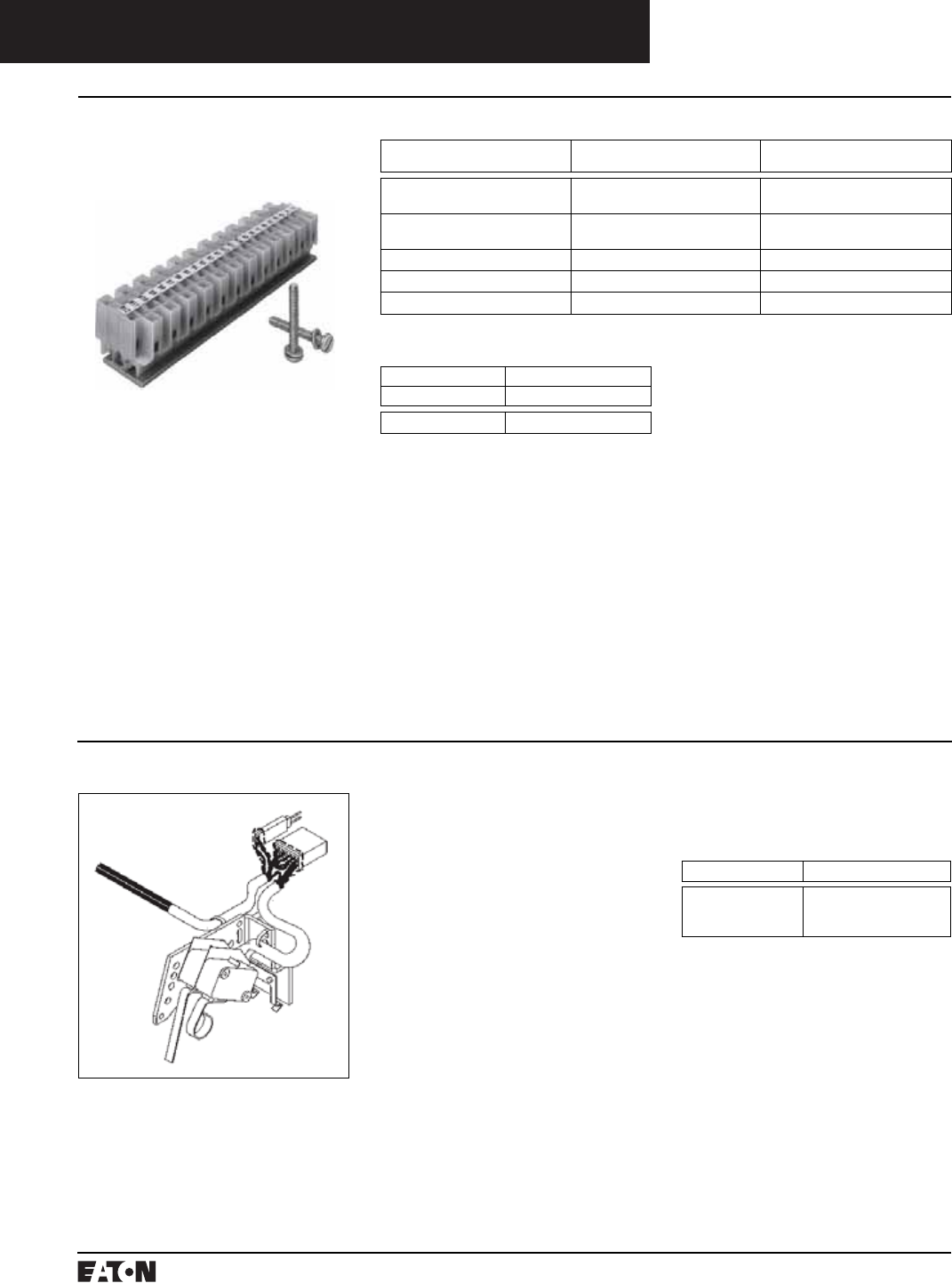
PG.74A.01.T.E
Cutler-Hammer
160 March 1999
Molded Case Circuit Breakers
Series C Internal Accessories
Accessory Terminal Block/Cutler-Hammer PowerNet Communications Kit (OPTIM 550 only)
Accessory Terminal Block
(R-Frame)
(For Fixed Mounted Configuration)
General Information
Internal accessory wiring leads are
normally supplied with pigtail leads
(No. 18 AWG) that exit from the right
side of the circuit breaker. Where
specified, fixed mounted accessory
terminal blocks are available. A max-
imum of one 24-point terminal block
can be installed on the right side of
the circuit breaker for the internal
accessories.
For convenience in determining the
appropriate number of terminal
block points required, refer to table
at right.
Number of Control Wires For Each Internally Mounted Accessories
Type of Accessory Number of Contacts Per Single
Accessory
Required Number of Wires
Auxiliary Switch 2a/2b
4a/4b
6
12
Alarm (Signal)/
Lockout Switch
1m/1b
2m/2b
6
12
Shunt Trip N/A 2
Low Energy Shunt N/A 2
Undervoltage Release Mechanism N/A 2
Ordering Information➀
Factory Installed Field Mounted
Suffix Number Catalog Number
Q01 TBRDK
Instruction Leaflet/FRED Number 29C312
➀One 24-point accessory terminal block
provided with circuit breaker when ordered
factory installed or shipped from warehouse
as separate item when ordered for field
installation. See Digitrip RMS master con-
nection diagram (IL 29C714).
Cutler-Hammer PowerNet Communications Kit (OPTIM 550 only) K-, L-, and N-Frames
General Information
The Cutler-Hammer PowerNet
Communications Kit can be ordered
to add Cutler-Hammer PowerNet
communications to an existing
OPTIM 550 breaker in the field. An
18-inch wiring pigtail is routed to the
rear of the breaker: two wires for
Cutler-Hammer PowerNet and two
wires for 24V Dc (45 mA load). It is
recommended that the power supply
be an “isolated high quality” unit.
Ordering Information
Cutler-Hammer PowerNet
Communications Kit
Circuit Breaker Catalog Numbers
K-Frame
L-Frame
N-Frame
ICK550K
ICK550L
ICK550N
Instruction Leaflet/FRED Number 29C506,
29C897, 29C898

March 1999
PG.74A.01.T.E
Cutler-Hammer 161
Molded Case Circuit Breakers
Series C External Accessories
Termination Hardware – Ring Type
Endcap Kit
The endcap kit slides onto the line or
load conductor of the circuit breaker
and acts as a threaded adapter for
the conductor to accept a ring termi-
nal or other bolt-on connector. The
endcap kit is available with English
and metric thread sizes. Screws and
washers are supplied by customer.
(Field installation only.) Listed per
UL File E7819.
Ordering Information
Thread Type Thread Size Catalog Number
Package of 12
(Priced Individually)
F-Frame
Imperial
Metric
10-32
M-5
KPEK1
KPEK1M
J-Frame
Imperial
Metric
10-32
M-5
KPEK2
KPEK2M
K-Frame
Imperial
Metric
10-32
M-5
KPEK3
KPEK3M
L-Frame
Imperial
Metric
10-32
M-5
KPEK4
KPEK4M
Keeper Nut
The keeper nut slides onto the line
or load conductor of the circuit
breaker and acts as a threaded
adapter for the conductor to accept
a ring terminal or other bolt-on con-
nector. The keeper nut is available
with English and metric thread sizes.
Screws and washers are supplied by
customer. (Field installation only.)
Listed per UL File E7819.
Ordering Information
F-Frame
Thread Type Thread Size Catalog Number
Package of 12
(Priced Individually)
Imperial
Metric
10-32
M-5
KPR1A
KPR1AM
Plug Nut
J-Frame
The plug nut is used in applications
where screw-connected ring-type
terminals are preferred to connect
cables to circuit breaker conductors.
The plug nut is press-fit into the
opening in the circuit breaker termi-
nal conductor. Screws and washers
are supplied by customer.
Ordering Information
Thread
Type
Thread
Size
Catalog Number
Package of 6
Imperial
Metric
.250-20
M-6
PLN2
PLN2M
K-Frame
L-, M-, N-Frames
Not required. Terminals are threaded.
Thread
Type
Thread
Size
Line/
Load End
Catalog
Number
Package of 3
Imperial .375-16 Line
Load
KPR3A
KPR3B
Metric M-8 Line
Load
KPR3AM
KPR3BM
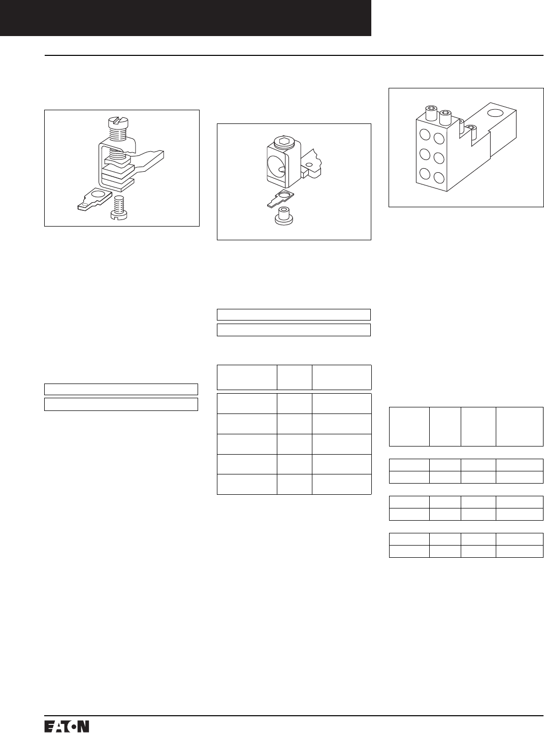
PG.74A.01.T.E
Cutler-Hammer
162 March 1999
Molded Case Circuit Breakers
Series C External Accessories
Termination Hardware – Control and Multi-Wire
Control Wire Terminal Kit
F-Frame
The control wire terminal kit pro-
vides a means to tap off control
power from a main disconnect using
the provided male end of a quick
disconnect.
For use with steel or stainless steel➀
terminals only.
Ordering Information
Package of 12 control wire terminal
tangs. Terminals must be ordered
separately. Priced individually.
Catalog Number
FCWTK
Multi-Wire Connectors
Field-installed multi-wire connec-
tors for the load side (OFF) end ter-
minals. They are used to distribute
the load from the circuit breaker to
multiple devices without the use of
separate distribution terminal
blocks.
Multi-wire lug kits include mounting
hardware, insulators and tin-plated
aluminum connectors to replace
three mechanical load lugs. UL
listed for copper only as used on the
load side (OFF) end.
Ordering Information
Package of 3.
Maximum
Amperes
Wires
Per
Terminal
Wire
Size
Range
AWG
Cu
Kit
Catalog
Number
F-Frame
225 3 #14-2 3TA150F3K
225 6 #14-6 3TA150F6K
J-Frame
225 3 #14-2 3TA250J3K
225 6 #14-6 3TA250J6K
K-Frame
400 3 #12-2/0 3TA400K3K
400 6 #14-2/0 3TA400K6K
➀Terminal kits contain one terminal for each
pole and one terminal cover.
➁Individually packed.
J- and K-Frames
Not for use with T250KB terminals.
Ordering Information
Package of 12 control wire terminal
tangs. Terminals must be ordered
separately. Priced individually.
L-Frame
Catalog Number
KCWTK
AWG Wire
Range/Number
Conductors
Metric
Wire
Range mm2
Catalog
Number
Al/Cu
(2) 250 – 350 kcmil
120-150 TA602LDCW➁
Cu
(2) 3/0 – 350 kcmil
120-150 T602LDCW➁
Al/Cu
(2) 400 – 500 kcmil
185-240 2TA603LDCW➀
2-Pole Kit
Al/Cu
(2) 400 – 500 kcmil
185-240 3TA603LDCW➀
3-Pole Kit
Al/Cu
(2) 400 – 500 kcmil
185-240 4TA603LDCW➀
4-Pole Kit
March 1999
PG.74A.01.T.E
Cutler-Hammer 163
Molded Case Circuit Breakers
Series C External Accessories
Base Mounting Hardware
Base Mounting Hardware
Ordering Information
Hardware for surface mounting of
circuit breakers is supplied only on
request. Hardware consists of
mounting screws and lockwashers.
Order hardware for circuit breaker
pole configurations as required.
Screw Length Style Number
G-Frame
2.625 (66.7 mm)
3.000 (76.2 mm)
624B375G23
8703C80G05
Imperial Thread Metric Thread
Number
of
Poles
Description Type of
Mounting
Style /
Catalog
Number
Number
of
Poles
Description Type of
Mounting
Style /
Catalog
Number
F-Frame
1 .164-32 x 3.188
inch Pan-
Head Steel
Screws,
Lockwashers,
and Clamps
Individual
Group
(one set of
hardware
for two
circuit
breakers)
624B375G01
624B375G02
1 M4 - 0.7 x
80 mm Pan-
Head Steel
Screws,
Lock-
washers,
and Clamps
Individual
Group
(one set of
hardware
for
two circuit
breakers)
4218B80G09
4218B80G10
2 .164-32 x 1.5
inch Pan-
Head
Steel Screws
and Lock-
washers
Individual 4218B80G01 2 M4 - 0.7 x
38 mm Pan-
Head Steel
Screws and
Lockwashers
Individual 4218B80G11
3, 4 .164-32 x 1.5
inch Pan-
Head
Steel Screws
and Lock-
washers
Individual BMH1 3, 4 M4 - 0.7 x
38 mm Pan-
Head Steel
Screws and
Lockwashers
Individual BMH1M
J-Frame
2, 3, 4 0.250-20 x 2.75
inch Pan-
Head Steel
Screws and
Lockwashers
Individual BMH2 2, 3, 4 M6 – 0.7 x
70mm Pan-
Head Steel
Screws and
Lockwashers
Individual BMH2M
K-Frame
2, 3, 4 0.250-20 x 1.5
inch Pan-
Head Steel
Screws and
Lockwashers
Individual BMH3 2, 3, 4 M6 – 0.7 x
38mm Pan-
Head Steel
Screws and
Lockwashers
Individual BMH3M
L-Frame
2, 3, 4 0.250-20 x 1.5
inch Filister-
Head Steel
Screws and
Lockwashers
and Flat
Washers
Individual BMH4 2, 3 – Individual BMH4M
M-Frame
2, 3 0.3125-18 x
1.25 inch
Filster-Head
Steel Screws
and
Lockwashers
and Flat
Washers
Individual BMH5 2, 3 – Individual BMH5M
N-Frame
2, 3, 4 0.3125-18 x
1.25 inch
Pan-Head
Steel Screws
and Lock-
washers
BMH5 2, 3 – Individual BMH5M
R-Frame
Supplied by customer
PG.74A.01.T.E
Cutler-Hammer
164 March 1999
Molded Case Circuit Breakers
Series C External Accessories
Drawout Cassette
Drawout Cassette
The drawout cassette is currently for
use with the standard 3-pole 65 kA/
480 Vac, 1600A and 2000A RD circuit
breakers only. It consists of two
separate components: the movable
mechanism which is factory
mounted to the circuit breaker frame
(shown in figure) and the stationary
mechanism which is housed in the
cassette and shipped separately.
The drawout mechanism has four
positions.
■Connected – The breaker is fully
connected to the primary stabs
and secondary contacts.
■Test – The breaker is not con-
nected to the primary stab but
is connected to the secondary
contacts.
■Disconnected – Both the primary
stabs and the secondary contacts
are disconnected.
■Withdraw – The breaker can be
removed from the cassette.
Note: Movable mechanism must
be ordered with RD or RDC circuit
breaker and is shipped mounted to
circuit breaker frame. Stationary
mechanism is ordered separately.
All internal accessories must be fac-
tory installed for use with drawout.
Ordering Information
RD Drawout Cassette
65 kA/480 Vac version
Description Catalog Number
Movable
Mechanism
RD20DOM
Stationary
Mechanism
RD20DOS
(without shutters)
RD20DOSS
(with shutters)
Instruction Leaflet/FRED Number 32697 Instruction Leaflet/FRED Number 32697
RD Drawout Cassette
100 kA/480 Vac version
Description Catalog Number
Movable
Mechanism
RD20DOM
Stationary
Mechanism
RD20DOS
(without shutters)
RD20DOSS
(with shutters)
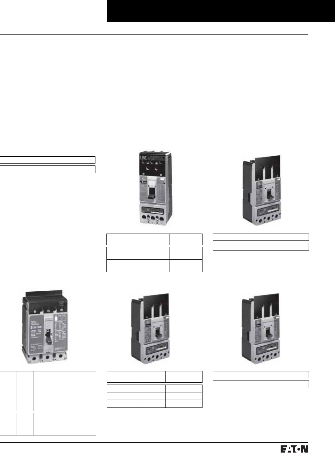
March 1999
PG.74A.01.T.E
Cutler-Hammer 165
Molded Case Circuit Breakers
Series C External Accessories
Termination Hardware – Protective Shields
J-Frame
Terminal Shields
Terminal shields provide protection
against accidental contact with live
line side terminations. Terminal
shields are fabricated from high
dielectric insulating material and
fasten over the front terminal access
openings. Small openings in the
shields provide limited access to the
terminals for tightening connectors.
(Field installation only.)
Ordering Information
G-Frame
Terminal Shield
Number Units in Package Style Number
10 GTSK3
L-Frame
F-Frame K-Frame M-Frame
Number of Poles Location Style Number
(Package of 10)
2, 3
4
Line End 1266C07G01
6631C01G01
2, 3
4
Load End 6641C16G01
6641C16G02
Style Number (Package of 1)
314CA420G01
Number
of Poles
Location Style Number
Standard
(Package of 10)
(Priced Individually)
Special - For
use when
electrical
operator is
mounted on
circuit
breaker
1
2
3
4
Line 625B229G06
625B229G07
625B229G08
625B229G09
–
–
4210B95G01
4210B95G02
Number of Poles Location Catalog Number
(Package of 10)
2, 3 Line TS33LN
4 Line TS34LN
3 Load TS33LD
Style Number (Package of 1)
4203B20G01
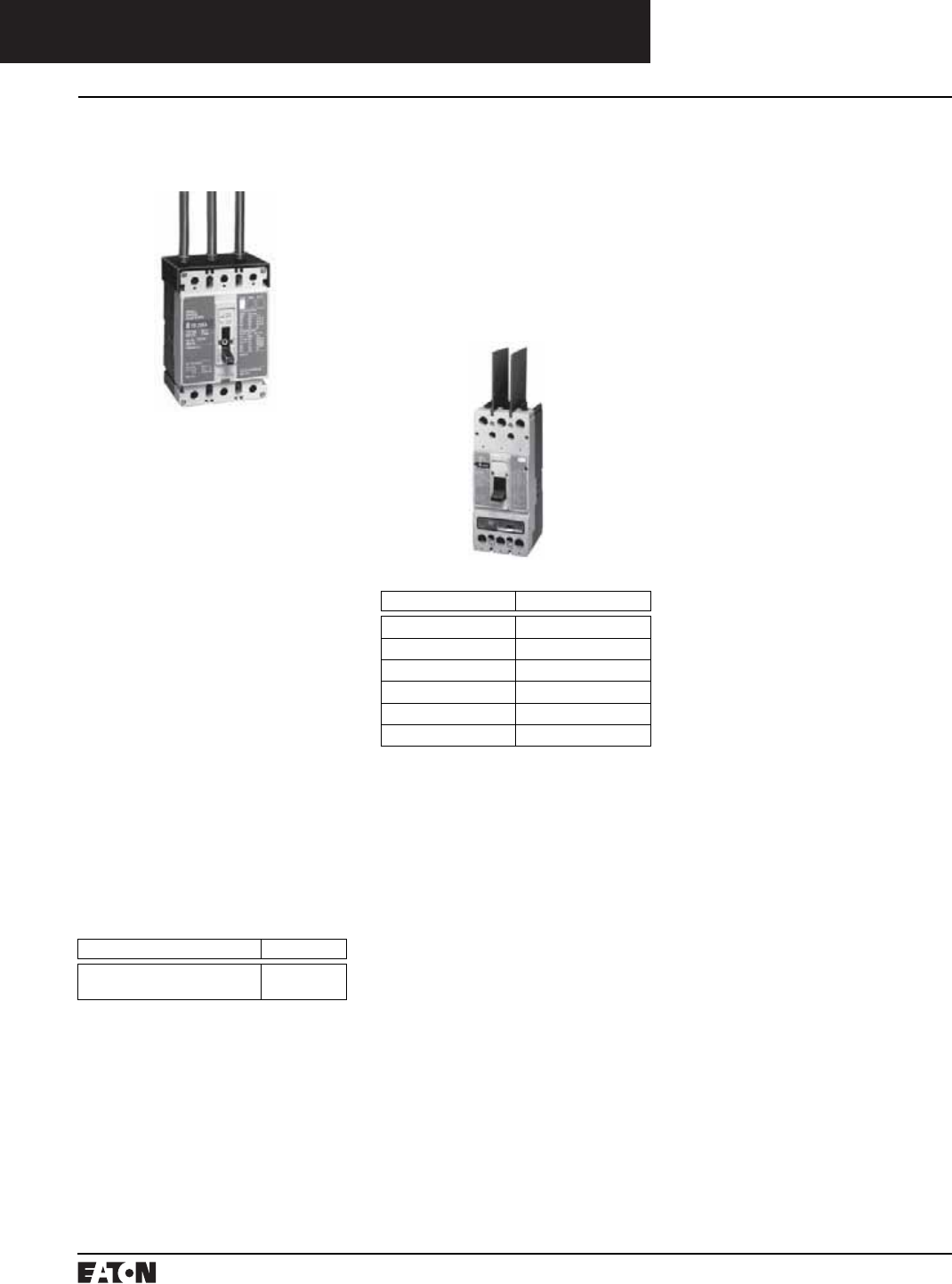
PG.74A.01.T.E
Cutler-Hammer
166 March 1999
Molded Case Circuit Breakers
Series C External Accessories
Termination Hardware
Terminal End Covers
F-Frame
The terminal end covers are
designed for use in motor control
center applications where, because
of confined spaces, line side conduc-
tors are normally custom fitted. The
molded end covers are made of high
dielectric glass-polyester and slide
over the line ends of the circuit
breaker. Close fitting conductor
openings are molded into the end
covers. The end cover and circuit
breaker case fit together to form
terminal compartments that isolate
discharged ionizing gases during cir-
cuit breaker tripping. Terminal end
covers are available with two con-
ductor opening diameters, 0.25 and
0.41 inch, and are listed per UL File
E7819. (Field installation only.)
Ordering Information
The terminal end cover is available
for 3-pole circuit breakers only. Two
conductor opening sizes are avail-
able. Specify quantity (one per
circuit breaker) when ordering.
Conductor Opening Diameter (Inches) Catalog Number
0.25 (6.35 mm)
0.41 (10.41 mm)
TEC1
TEC2
Interphase Barriers
The interphase barriers provide
additional electrical clearance
between circuit breaker poles for
special termination applications.
The barriers are high dielectric insu-
lating plates that are installed in the
molded slots between the terminals.
(Field installation only.) Two per
package.
Frame Catalog Number
F IPB1
J IPB2
K IPB3
L IPB4
M IPB4
N IPB5
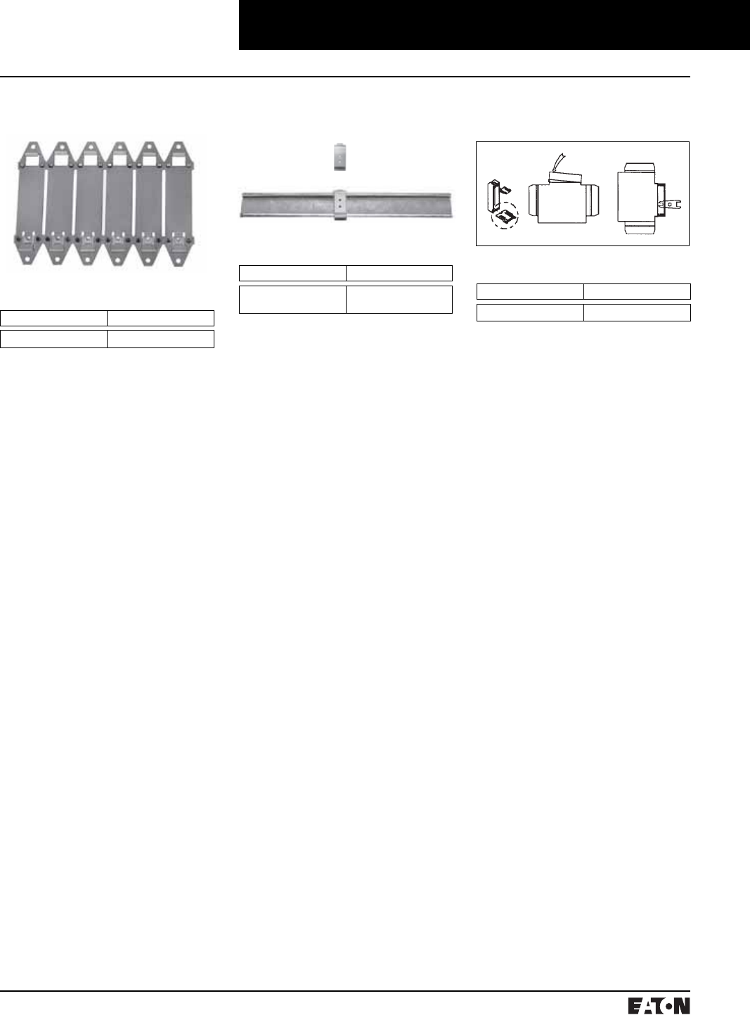
March 1999
PG.74A.01.T.E
Cutler-Hammer 167
Molded Case Circuit Breakers
Series C External Accessories
Base Mounting Adapters
Base Mounting Plate➀
G-Frame GD/GC/GHC
➀Suitable for mounting (6) single-pole circuit
breakers.
➁For use with standard 35 mm DIN Rail such
as, 35 x 7.5 or 35 x 15 mm per DIN EN50022.
➂Adapter mounting screws included are for
use with 2- and 3-pole circuit breakers.
Adapters for 1-pole circuit breakers clip into
the base molding.
➃For use on 3-pole breakers only.
DIN Rail Adapter➁➂
G-Frame GD/GC/GHC
Ordering Information
Number Units in Package Style Number
10
10
1225C79G01
1225C79G02➃
Key Operated Attachment
G-Frame GD/GC/GHC
Ordering Information
Number Units in Package Style Number
10 GK0A
Ordering Information
Number Units in Package Style Number
1 207B513G01 Instruction Leaflet/FRED Number 29C090
Instruction Leaflet/FRED Number 29C091
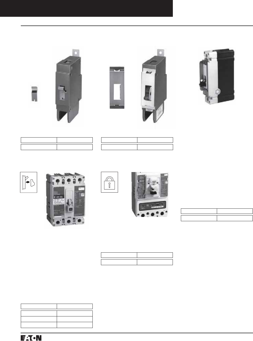
PG.74A.01.T.E
Cutler-Hammer
168 March 1999
Molded Case Circuit Breakers
Series C External Accessories
Handle Locking and Blocking Devices
Padlockable Handle
G-Frame GD/GC/GHC/GB/GHB
Lock Dog (non-padlockable)
G-Frame GD/GC/GHC/GB/
GHB/GMCP
Ordering Information
Number Units in Package Style Number
1 1294C01H01
Ordering Information
(Accepts .285 Lock Shank)
Number Units in Package Style Number
10 1223C77G03
Non-Padlockable
Handle Block
Snap-On Padlockable
Handle Lock Hasp
The snap-on padlockable handle
lock allows the handle to be locked
in the OFF or ON position. (Trip-free
operation allows the circuit breaker
to trip when the handle lock holds
the circuit breaker handle in the ON
position.) This device was designed
for use on the 1-pole circuit breaker,
but may be used on 1-, 2-, 3-, and
4-pole styles. The handle lock snaps
onto the escutcheon area of the han-
dle with an optional retaining screw
for added secureness. The handle
lock will accommodate one padlock
with a 1/4-inch (6 mm) shackle.
Listed per UL File E7819. (Field
installation only.)
Ordering Information
Frame Catalog Number
F PHB1
Padlockable Handle Block
The device is positioned in the
cover opening to prevent handle
movement. Will accommodate one
5/16 padlock.
Ordering Information
Frame Catalog Number
J, K PHB3
The nonlockable handle block
secures the circuit breaker handle
in either the ON or OFF position.
(Trip-free operation allows the cir-
cuit breaker to trip when the handle
block holds the circuit breaker han-
dle in the ON position.) The device is
positioned over the circuit breaker
handle and secured by a setscrew to
deter accidental operation of the
circuit breaker handle. Listed per UL
File E7819. (Field installation only.)
Ordering Information
Frame Catalog Number
F LKD1
J, K LKD3
L, M, N LKD4
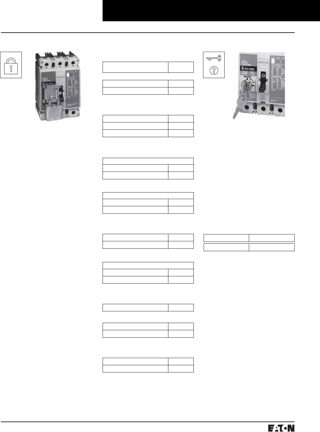
March 1999
PG.74A.01.T.E
Cutler-Hammer 169
Molded Case Circuit Breakers
Series C External Accessories
Handle Locking and Blocking Devices
The padlockable handle lock hasp
allows the handle to be locked in the
ON or OFF position. (Trip-free opera-
tion allows the circuit breaker to trip
when the handle lock holds the cir-
cuit breaker handle in the ON posi-
tion.) The hasp mounts on the circuit
breaker cover within the trimline.
The cover is predrilled on both sides
of the operating handle so that the
hasp can be mounted on either side
of the handle. The hasp will accom-
modate up to three padlocks with
1/4-inch (6 mm) shackles. Listed per
UL File E7819. (Field installation only.)
The padlockable handle lock can be
mounted on either side of the operat-
ing handle. One per circuit breaker.
(Field installation only.)
Padlockable Handle Lock Hasp
Ordering Information
Description Catalog
Number
F-Frame
1-pole breakers PHL1
2-, 3-, 4-pole breakers PLK1
Instruction Leaflet/FRED Number 29C230
J, K-Frames
2-, 3-, 4-pole breakers PLK3
For Left Side Mounting PLK3LOFF➀
For Right Side Mounting PLK3ROFF➀
Instruction Leaflet/FRED Number 29C232
L-Frame
Side Mounted
Lock On or Off HLK4
Lock Off Only (Left-Hand Mount) HLK4LOFF➀
Instruction Leaflet/FRED Number 29C234
Top Mounted
Lock On or Off HLK4S
Lock Off Only HLK4SOFF➀
Instruction Leaflet/FRED Number 29C234C
M-Frame
Lock On or Off HLK4
Lock Off Only (Left-Hand Mount) HLK4LOFF➀
Instruction Leaflet/FRED Number 29C234
Vertical Mounting
Lock On/Off HLK45
Lock Off Only HLK45OFF
Instruction Leaflet/FRED Number 29C234C
N-Frame
Side Mounted PLK5
Instruction Leaflet/FRED Number 29C234
Top Mounted (On/Off) PLK5S
Top Mounted (Off Only) PLK5SOFF➀
Instruction Leaflet/FRED Number 29C234C
R-Frame
Lock On/Off HLK6
Lock Off Only HLK6OFF➀
Instruction Leaflet/FRED Number 29C240
➀For padlockable handle lock hasp to padlock
handle in OFF position only order either
catalog number.
Cylinder Lock
The cylinder lock internally blocks the
trip bar in the tripped position to pre-
vent the circuit breaker from being
switched to ON. The cylinder lock is
factory installed in the circuit breaker
cover. Other internally mounted
accessories cannot be installed in
the same pole as the cylinder lock.
(Factory installation only.)
The cylinder lock is factory installed
in the left pole only of the circuit
breaker cover. Internal accessories
cannot be installed in the same pole
as the cylinder lock.
Ordering Information
Frames Catalog Number
F, J, K Order by description
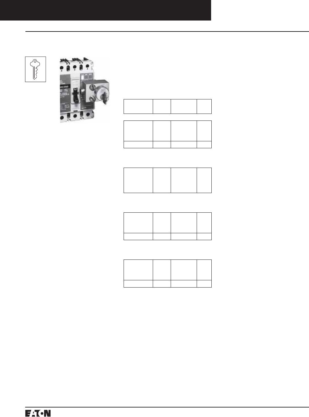
PG.74A.01.T.E
Cutler-Hammer
170 March 1999
Molded Case Circuit Breakers
Series C External Accessories
Mechanical Interlocking Devices
The key interlock is used to exter-
nally lock the circuit breaker handle
in the OFF position. When the key
interlock is locked, an extended
deadbolt blocks movement of the cir-
cuit breaker handle. Uniquely coded
keys are removable only with the
deadbolt extended. Each coded key
controls a group of circuit breakers
for a given specific customer
installation.
The key interlock assembly is Under-
writers Laboratories, Inc., listed for
field installation under UL file E7819
and consists of a mounting kit and a
purchaser supplied deadbolt lock.
The mounting kit comprises a
mounting plate, which is secured to
the circuit breaker cover in either the
left- or right-pole position, key inter-
lock mounting screws, and a wire
seal. Specific mounting kits are
required for individual key interlock
types.
Key Interlock Kit
(Lock Not Included)
Ordering Information
Key interlock mounting kits are for
field installation only. Select mount-
ing kit catalog numbers to match
type of lock used. Key interlocks are
supplied by customer.
Lock
Manufacturer
Lock
Type
Bolt Projection
in Withdrawn
Position
Kit
Catalog
Number
F-Frame
Superior
Kirk
Square D
Federal Pioneer
B-4003-1
F
SF
VF
3/8 inch
3/8 inch
None
3/8 inch
KYK1
Castell K or QK 3/8 inch CTK1
J-, K-Frames
Superior
Kirk
Square D
Federal Pioneer
Castell
B-4003-1
F
SF
VF
K or QK
3/8 inch
3/8 inch
None
3/8 inch
3/8 inch
KYK3
L-, M-, N-Frames
Superior
Kirk
Square D
Federal Pioneer
B-4003-1
F
SF
VF
3/8 inch
3/8 inch
None
3/8 inch
KYK4
Castell K or QK 3/8 inch CTK4
R-Frame
Superior
Kirk
Square D
Federal Pioneer
B-4003-1
F
SF
VF
1 inch
1 inch
1 inch
1 inch
KYK6
Castell K or QK 1 inch CTK6
Instruction Leaflet/FRED Number 29C231
Instruction Leaflet/FRED Number 29C233
Instruction Leaflet/FRED Number 29C235
Instruction Leaflet/FRED Number 29C240
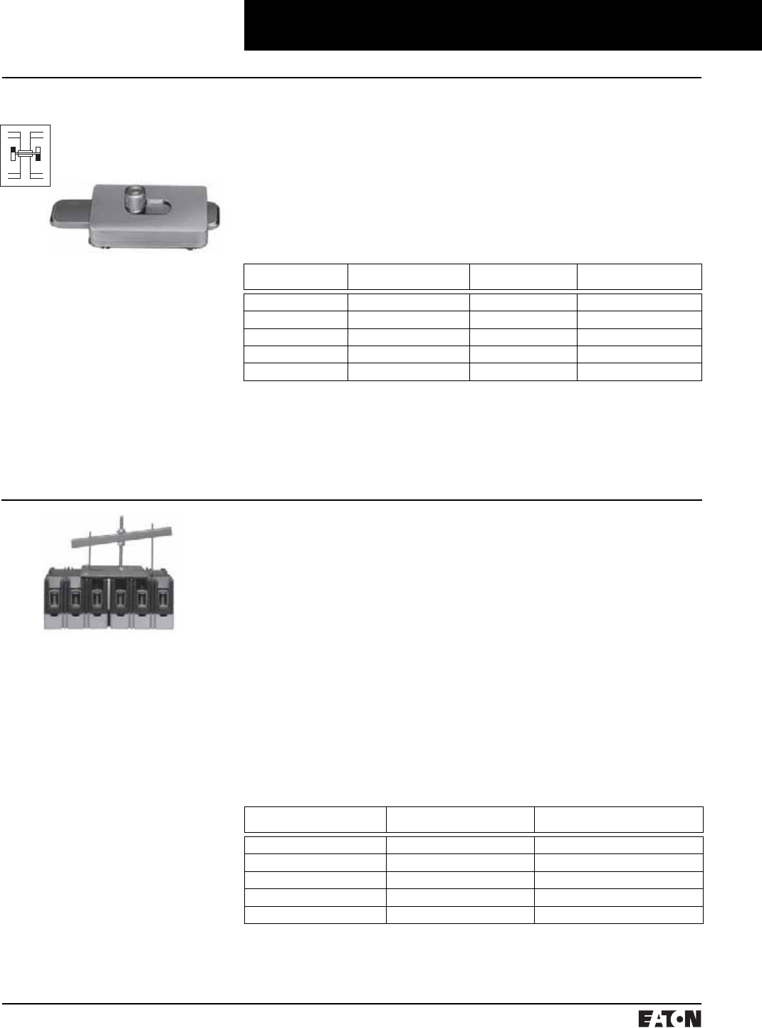
March 1999
PG.74A.01.T.E
Cutler-Hammer 171
Molded Case Circuit Breakers
Series C External Accessories
Mechanical Interlocking Devices
Ordering Information
The sliding bar interlock is available
for mounting between two adjacent
3-pole circuit breakers with circuit
breakers centerline spacing as indi-
cated in table and enclosure front
panel thickness of 1/8 or 3/16 inch.
(For field installation only.)
Sliding Bar Interlock
The sliding bar interlock provides
mechanical interlocking between
two adjacent 3-pole circuit breakers.
It is installed on the enclosure cover
between the circuit breakers. When
the sliding bar interlock handle is
moved from one side to the other,
a bar extends to alternately block
movement of the circuit breaker
handles and prevents both circuit
breakers from being switched to ON
at the same time. Sliding bar inter-
locks are not UL listed. (Field install-
ation only.)
➤
➤
Walking Beam Interlock
The walking beam interlock provides
mechanical interlocking between
two adjacent circuit breakers of the
same pole configuration. The walk-
ing beam interlock mounts on a
bracket behind and between the cir-
cuit breakers. A plunger on each end
of the beam is inserted through an
access hole in the back plate and
base of each circuit breaker. The
walking beam interlock prevents
both circuit breakers from being
switched ON at the same time. If a
walking beam interlock is installed,
the wiring troughs in the back of the
circuit breaker case are blocked by
the plungers and cannot be used for
cross wiring. Factory modified cir-
cuit breakers are required for this
application. UL File E3816.
Ordering Information
The walking beam interlock is avail-
able for mounting between two adja-
cent circuit breakers spaced 1/4-inch
apart and having the same pole con-
figuration. The two circuit breakers
must be factory modified to accept
the walking beam interlock assembly
(suitable for use with either 2-, 3-, or
4-pole circuit breakers). With properly
modified circuit breakers, the walking
beam interlock is suitable for field
installation. Order circuit breakers
specifying modification for walking
beam and select walking beam inter-
lock from table on this page. Circuit
breakers and walking beam interlock
are boxed and shipped separately.
Frame Centerline Spacing
(inches)
Catalog Number Instruction Leaflet/
FRED Number
F 4-3/16 SBK1 29C310
J 4-3/8 SBK2 29C310
K 5-3/4 SBK3 29C310
L, M 8-1/2 SBK4 29C311
N 8-1/2 SBK5 46A8396
Frame Catalog Number Instruction Leaflet/
FRED Number
F WBL1 29C300
K WBL3 29C301
L, M WBL4 29C302
N WBL5 29C303
R WBL6 29C304
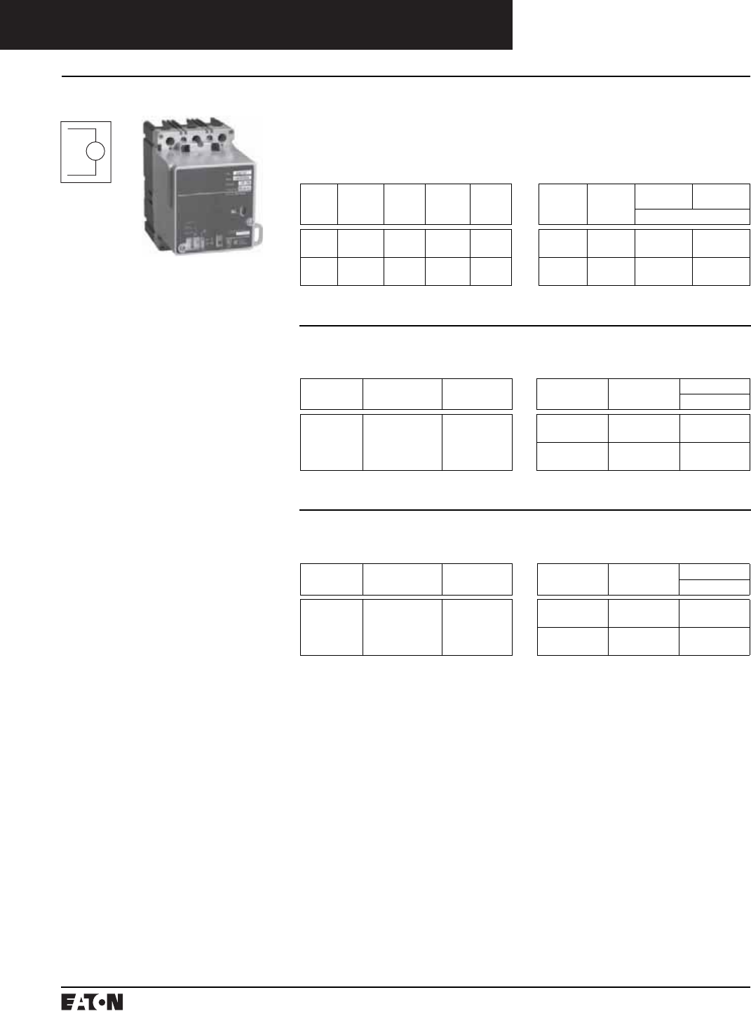
PG.74A.01.T.E
Cutler-Hammer
172 March 1999
Molded Case Circuit Breakers
Series C External Accessories
Electrical Operator
The electrical (solenoid) operator is
a single solenoid mechanism that
enables local and remote circuit
breaker ON, OFF, and reset switch-
ing. The electrical operator is
mounted on the circuit breaker
cover within the trimline of the cir-
cuit breaker. The electrical operator
uses a unique bistable latch that
allows the device to operate using
one solenoid. The accessory pro-
vides high-speed switching with a
maximum operating time of 5 cycles
(80 ms) making it suitable for gener-
ator synchronizing applications.
Means are provided for remote elec-
trical operation and for local manual
operation. A special slide includes
provisions for padlocking the circuit
breaker handle in the OFF position.
The slide will accept three padlock
shackles with a maximum diameter
of 1/4-inch (6 mm) each. An interlock
electrically disconnects the solenoid
when the electrical operator cover is
removed. The above table provides
electrical rating data for the electri-
cal (solenoid) operator.
The electrical (solenoid) operator is
Underwriters Laboratories, Inc.,
listed as a circuit breaker accessory
under UL File E64983.
EO
Electrical Operator➀
➀The electrical operator design is endurance
tested for 10,000 electrical operations.
➁Use current-limiting type fuse where
required.
➂Tolerance: +10%, –15% of nominal voltage.
➃Tolerance: ±10% of nominal voltage.
➄Underwriters laboratories listed under UL
file E64983.
➅The electrical operator design has been
endurance tested for 6,000 electrical
operations.
➆Frequency: 50/60 Hz.
➇Maximum operating time: 5 cycles (80 ms).
Ordering Information
F-Frame
Electrical Rating Data➁ Electrical Operator
Voltage Frequency Inrush
Current
Amperes
Maximum
Operating
Time
Fuse➂
Amperes
Voltage Frequency Terminal
Block
18-Inch
Pigtail Lead
Catalog Number
120➃
240➃
50/60 Hz
Ac
10
5
5 cycles
(80 ms)
3
2
120
240
Ac EOP1T07
EOP1T11
EOP1P07
EOP1P11
120➄
240➄
Dc
Dc
14
8
5 cycles
(80 ms)
3-5
2-3
120
240
Dc EOP1T07DC
EOP1T11DC
EOP1P07DC
EOP1P11DC
K-Frame
Electrical Rating Data ➄➅➆➇ Electrical Operator
Voltage (V)➂ Inrush Current (A) Fuse (A) Operating
Voltage
Frequency Terminal Block
Catalog Number
120
240
24
12
6
4
120
240
50/60 Hz
Ac
EOP3T07
EOP3T11
120
240
Dc EOP3T07DC
EOP3T11DC
J-Frame
Electrical Rating Data ➄➅➆➇
Voltage (V)➂ Inrush Current (A) Fuse (A)
120
240
24
12
6
4
Electrical Operator
Operating
Voltage
Frequency Terminal Block
Catalog Number
120
240
50/60 Hz
Ac
EOP2T07
EOP2T11
120
240
Dc EOP2T07DC
EOP2T11DC
Instruction Leaflet/FRED Number 29C202 (AC); 29C211 (DC)
Instruction Leaflet/FRED Number 29C202 (AC); 29C211 (DC)
Instruction Leaflet/FRED Number 29C200 (AC); 29C210 (DC)
March 1999
PG.74A.01.T.E
Cutler-Hammer 173
Molded Case Circuit Breakers
Series C External Accessories
Electrical Operator
The motor operator allows the cir-
cuit’s breaker to be opened, closed,
or reset remotely. It also has a lock-
off capability and provisions for
manual operation.
The motor operator contains a
reversible motor connected to a ball
screw. The ball screw drives the cir-
cuit breaker handle. Limit switches
and relays are used to control the
motor.
The motor operator is UL listed as a
recognized component suitable for
field installation on all type L-frame
circuit breakers and molded case
switches under UL File E64124.
From the point of energization of the
closing mechanism at 85% voltage,
the closing time is 30 cycles ± 10%.
Ordering Information
L- and M-Frames
Electrical Rating Data ➀➁➂➃ Electrical Operator
Voltage (V)➄ Inrush Current (A) Operating
Voltage
Frequency Terminal Block
Catalog Number
120 Ac
208
240
8
5
4
120
208
240
480
50/60 Hz EOPM4T07
EOPM4T11
EOPM4T11A
EOPM4T15
125 Dc
24
9
27
125
24
Dc EOPM4T26
EOPM4T21
N-Frame
Electrical Rating Data ➀➂➅➆ Electrical Operator
Voltage
(V)➄
Frequency Inrush
Current (A)
Fuse
(A)
Operating
Voltage
Frequency Pigtail Leads
Catalog Number
120
208
240
480
50/60 Hz 25
21
19
6
4
120
208
240
480
50/60 Hz EOP5T07
EOP5T09
EOP5T11
EOP5T15
48
125
Dc 80
13
48
125
Dc EOP5T22
EOP5T26
R-Frame
Available Motor Operator Ratings
and Operating Conditions➇➈➉Electrical Operator
Rating
Voltage (V)
Frequency Motor Inrush
Current (A)
Operating
Voltage
Frequency Factory Installed
Terminal Block
Catalog Number
120
240
48
50/60 Hz
50/60 Hz
Dc
40
27
53
120
240
48
50/60 Hz
50/60 Hz
Dc
EOP6T08K
EOP6T11K
EOP6T21K
➀Underwriters Laboratories Inc. listed under
UL File E64983.
➁The electrical operator design has been
endurance tested for 6,000 electrical
operations.
➂Frequency: 50/60 Hz.
➃Maximum operating time: 5 cycles (80 ms).
➄Tolerance: +10%, –15% of nominal voltage.
➅The electrical operator design has been
endurance tested for 2,500 electrical
operations.
➆Maximum operating time: 12 cycles max.
Operator is an intemittent duty device. The
safe duty cycle (OFF to ON to OFF) should
not exceed one per minute.
➇Operator is an intermittent duty service. The
safe duty cycle (OFF to ON to OFF) should
not exceed one per minute.
➈Electric Operating time at rated voltage;
(a) To turn breaker ON – 1/2 second max.
(b) To turn breaker OFF – 1/2 second max.
➉Motor operating temperature; Class “A”
temperature limits apply.
A minimum 1 kVA power source is recom-
mended for motor operation.
Applied voltage should be no less than 85%
or no more than 110% of rated.
Instruction Leaflet/FRED Number 29C203
Instruction Leaflet/FRED Number 29C204
Instruction Leaflet/FRED Number 29C205
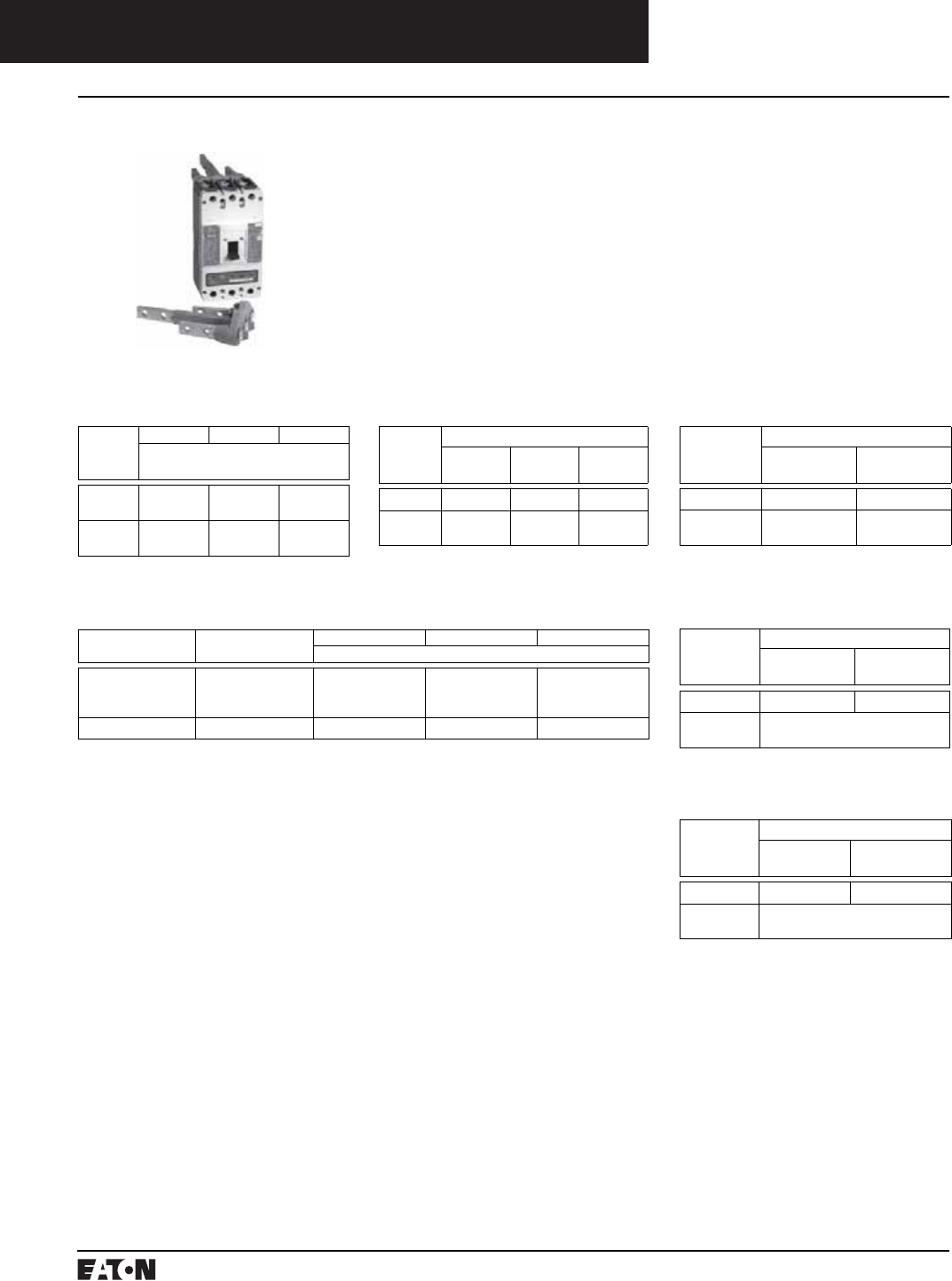
PG.74A.01.T.E
Cutler-Hammer
174 March 1999
Molded Case Circuit Breakers
Series C External Accessories
Plug-in Adapters
Ordering Information
F-Frame
Continuous
Current
Rating
(Amperes)
2-Pole 3-Pole 4-Pole
Style Number
100
150-225
507C036G13
507C036G14
507C036G15
507C036G16
179C968G03
179C968G04
Mounting
Plate
176C511H01 507C047H01 ➀
Plug-in adapters simplify installa-
tion and front removal of circuit
breakers. Individual line and load
plug-in adapters are available for
rear connection applications on
2-, 3-, and 4-pole circuit breakers.
Common mounting plates for line-
and load-end adapters are available.
➀Refer to Cutler-Hammer for availability.
➁Use 3-pole mounting plate for 2-pole circuit
breaker.
J-Frame
Continuous Current
Rating (Amperes)
Terminal End 2-Pole 3-Pole 4-Pole
Style/Catalog Number
250 Line
Load
1 Line and 1 Load
1260C86G05
1260C86G07
506C144G27
1260C86G06
1260C86G08
506C144G28
1231C67G01
1231C67G02
–
Mounting Plate – ➁ PMP23 –
N-Frame
Continuous
Current
Rating
(Amperes)
Style Number
2-Pole 3-pole
1200 2614D53G03 2614D53G04
Mounting
Plate
1290C73H01
Plug-in Adapters
K-Frame
Continuous
Current
Rating
(Amperes)
Catalog Number
2-Pole 3-pole 4-Pole
400 PAD32 PAD33 PAD34
Mounting
Plate
➁ PMP33 PMP34
Instruction Leaflet/FRED Number 13782
Instruction Leaflet/FRED Number 149321
Instruction Leaflet/FRED Number 15378 Instruction Leaflet/FRED Number 29C314
Instruction Leaflet/FRED Number 15073
Instruction Leaflet/FRED Number 13782
L-Frame
Continuous
Current
Rating
(Amperes)
Catalog Number
2-Pole 3-pole
600 506C059G03 506C059G04
Mounting
Plate
504C824H01 504C824H01
M-Frame
Continuous
Current
Rating
(Amperes)
Catalog Number
2-Pole 3-Pole
800 2614D53G05 2614D53G06
Mounting
Plate
1290C73H01
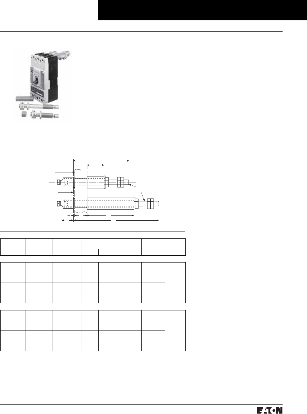
March 1999
PG.74A.01.T.E
Cutler-Hammer 175
Molded Case Circuit Breakers
Series C External Accessories
Rear Connecting Studs
E
B
AC
D
3
4
1
16
Mounting Panel
Breaker Mounting
Surface
“F” Thread
Rear Connecting Studs
Ordering Information
F-Frame
Stud
Ampere
Rating
Stud Style
Number
Panel Thickness
(Inches)
Tube Length
(Inches)
Tube
Style
Number
Dimensions
(Inches)
ABC DEF
For 15A to 100A Circuit Breakers
100A Short
100A Short
100A Short
100A Short
451D874G01
451D874G01
451D874G01
451D874G01
1
1-1/16 to 15/16
3/8 to 5/8
1/4 to 5/16
11/16
13/8
1-11/16
2
–
–
–
–
32B9446H20
32B9446H21
32B9446H22
32B9446H23
–
–
–
–
3-5/8 15/16 - 18
100A Long
100A Long
100A Long
100A Long
451D874G02
451D874G02
451D874G02
451D874G02
1
1-1/16 to 15/16
3/8 to 5/8
1/4 to 5/16
–
–
–
–
3-7/16
3-3/4
4-1/16
4-3/8
32B9446H24
32B9446H25
32B9446H26
32B9446H27
6-1/8 –
–
–
–
For 110A to 150A Circuit Breakers
150A Short
150A Short
150A Short
150A Short
374D883G01
374D883G01
374D883G01
374D883G01
1
11/16 to 15/16
3/8 to 5/8
1/4 to 5/16
11/16
13/8
1-11/16
2
–
–
–
–
374D883H06
374D883H07
374D883H08
374D883H09
–
–
–
–
4-1/4 1/16 - 14
150A Long
150A Long
150A Long
150A Long
374D883G02
374D883G02
374D883G02
374D883G02
1
11/16 to 15/16
3/8 to 5/8
1/4 to 5/16
–
–
–
–
3-7/16
3-3/4
4-1/16
4-3/8
374D883H10
374D883H11
374D883H12
374D883H13
7-1/2 –
–
–
–
Rear connecting studs are available
in several sizes to accommodate
specific fixed-mounted circuit
breaker applications.
Each rear connecting stud assembly
consists of one stud and one tube.
To maintain proper clearances
between poles, select alternate long
and short stud assemblies for circuit
breakers with more than one pole.
One assembly is required for line-
end and one for load-end of each
pole. Tubes must be ordered sepa-
rately. Connecting studs are avail-
able only with English thread sizes.
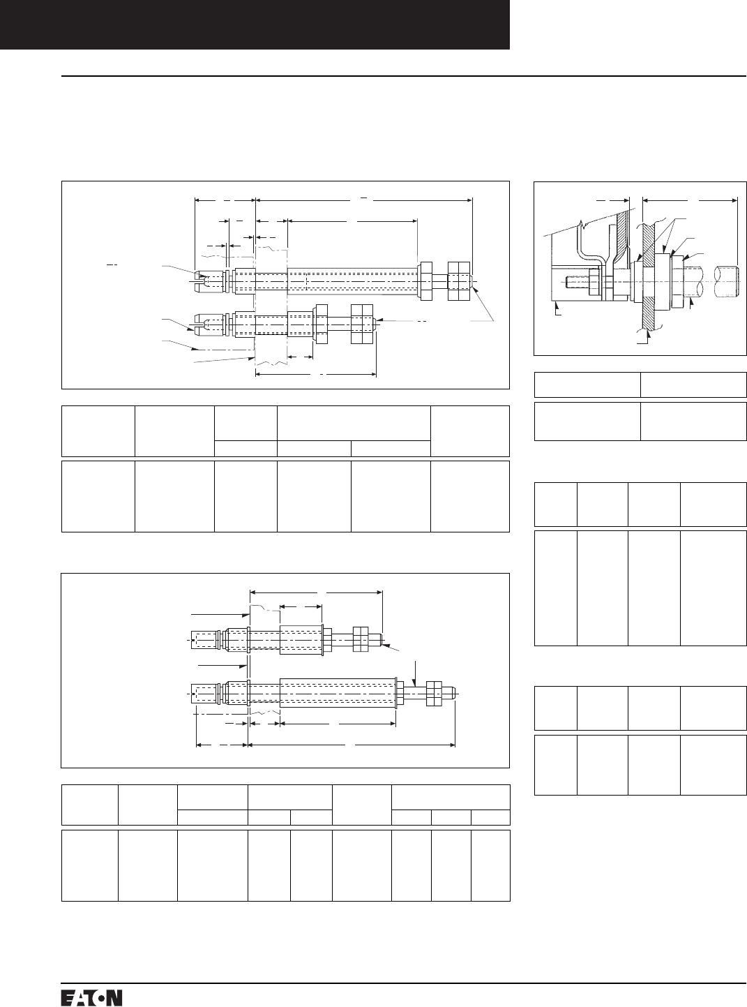
PG.74A.01.T.E
Cutler-Hammer
176 March 1999
Mounting Panel
Breaker Mounting
Surface
“F” Thread
C
A
D
B
E
1
16
1
43
64
Molded Case Circuit Breakers
Series C External Accessories
Rear Connecting Studs
Rear Connecting Studs
Ordering Information
J-Frame
Stud
Ampere
Rating
Stud Style Number Panel
Thickness
(Inches)
Tube Length
(Inches)
Tube Style Number
AB C
250A Short
250A Short
250A Short
250A Long
250A Long
250A Long
5010D23G01
5010D23G01
5010D23G01
5010D23G02
5010D23G02
5010D23G02
3/4 – 1
1/2 – 3/4
1/4 – 1/2
3/4 – 1
1/2 – 3/4
1/4 – 1/2
27/32
1-3/32
1-1/32
–
–
–
–
–
–
37/8
41/8
43/8
456D983H05
456D983H06
456D983H07
5010D23H05
5010D23H06
5010D23H07
Mounting Panel
Do Not Use More
Than 10 Ft. Lbs.
Torque to Tighten Nuts 13 Thread
1
2
C
A
3
5
8
6
21
32
18 Thread
5
16
Breaker
B
1
19
32
19
32
1
16
1
32
Stud
Length
Stud Style
Number
Panel Thickness
(Inches)
Tube Length
(Inches)
Standard
Tube Style
Number
Dimensions
(Inches)
ABC DEF
400A Short
400A Short
400A Short
400A Long
400A Long
400A Long
6642C14G02
6642C14G04
6642C14G06
6642C14G03
6642C14G05
6642C14G07
3/4 to 1
1/2 to 3/4
1/4 to 1/2
3/4 to 1
1/2 to 3/4
1/4 to 1/2
27/32
1-3/32
1-11/32
–
–
–
–
–
–
3-25/32
4-1/32
4-9/32
313C909H17
313C909H18
313C909H19
313C909H20
313C909H21
313C909H22
–
–
–
–
6-37/64
–
3-21/32 3/4 - 16
K-Frame
Stud Length
(A)
Stud Style
Number
5-15/32
7-31/32
10-15/32
314C960G07
314C960G08
314C960G09
M-Frame➀
Stud
Ampere
Rating
Diameter,
Inches
and
Thread
Extension
Back of
Breaker,
Inches
Stud
Style
Numbers
225
400
400
400
600
600
600
800
800
800
1/2-13
3/4-16
3/4-16
3/4-16
1-12
1-12
1-12
1-1/8-12
1-1/8-12
1-1/8-12
3-21/32
5-29/32
8-13/32
10-29/32
5-29/32
8-13/32
10-29/32
5-29/32
8-13/32
10-29/32
314C960G01
314C960G04
314C960G05
314C960G06
314C960G07
314C960G08
314C960G09
314C960G10
314C960G11
314C960G12
N-Frame➀
Stud
Ampere
Rating
Diameter,
Inches
and
Thread
Extension
Back of
Breaker,
Inches
Stud
Style
Numbers
800
800
800
1200
1200
1-1/8-12
1-1/8-12
1-1/8-12
1-1/4-12
1-1/4-12
5-1/2
8
10-1/2
5-1/2
10-1/2
623B222G01
623B222G02
623B222G03
373B375G04
373B375G03
L-Frame
A
Insulators
Nut
Rear
Connecting
Stud
Washer
Insulating Panel
Circuit Breaker
7
16
➀Not UL listed.
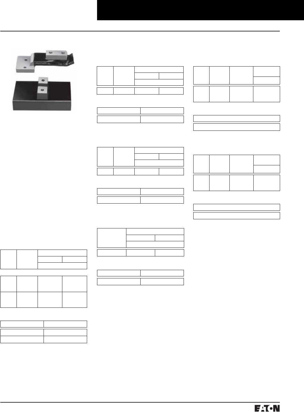
March 1999
PG.74A.01.T.E
Cutler-Hammer 177
Molded Case Circuit Breakers
Series C External Accessories
Panelboard Connecting Straps
Panelboard Connecting Straps
J-Frame
Panelboard Connecting Straps
Bus
Spacing
(Inches)
Continuous
Current
Rating
(Amperes)
Pole Connector Type
Center Outside
Style Number
3-1/2 250 2600D26G01 2600D26G02
Panelboard connecting straps are
used to connect the circuit breaker
terminals to the panelboard bus.
The panelboard connecting straps
are available with various ratings for
outside and center poles. (Field
installation only.)
Ordering Information
Panelboard connecting straps are
available to meet the needs of most
standard panelboard applications.
Style numbers for mounting brack-
ets for CDP panelboard installations
are also included.
Refer to panelboard manufacturer
for compatibility.
K-Frame
Panelboard Connecting Straps
Bus
Spacing
(Inches)
Continuous
Current
Rating
(Amperes)
Pole Connector Type
Center Outside
Style Number
3-1/2 400 4212B78G02 4212B77G01
L-Frame
Panelboard Connecting Straps
Continuous
Current
Rating
(Amperes)
Pole Connector Type
Center Outside
Style Number
600 624B609G01 506C052G01
M-Frame
Panelboard Connecting Straps
Bus
Spacing
(Inches)
Continuous
Current
Rating
(Amperes)
Connector
Type
Pole Connector
Type
Style Number
3-1/2 800 Short
Medium
Long
314C996G01
314C996G02
314C996G03
Mounting Bracket
Style Number
315C270H01
N-Frame
Panelboard Connecting Straps
Bus
Spacing
(Inches)
Continuous
Current
Rating
(Amperes)
Connector
Type
Pole Connector
Type
Style Number
3-1/2 1200 Short
Medium
Long
505C606G04
505C606G05
505C606G06
Mounting Bracket (Four (4) Required)
Style Number
315C270H01
Mounting Bracket
Number of Poles Style Number
2 624B600H02
3 624B600H01
F-Frame
Panelboard Connecting Straps
Bus
Spacing
(Inches)
Continuous
Current
Rating
(Amperes)
Pole Connector Type
Center Outside
Style Number
5-3⁄4-Inch Deep Box, 600 Vac Maximum
2-3/4
2-3/4
2-3/4
50
100
150
673B142G02
673B142G02
673B142G04
673B142G09
673B142G10
673B142G03
3-1/2
3-1/2
3-1/2
50
100
150
1253C72G01
1253C73G03
1253C73G01
1253C72G03
1253C73G06
1253C73G05
Mounting Bracket
Number of Poles Style Number
2, 3 208B297H01
Mounting Bracket
Number of Poles Style Number
2, 3 208B264H01
Mounting Bracket
Number of Poles Style Number
2, 3 1576707
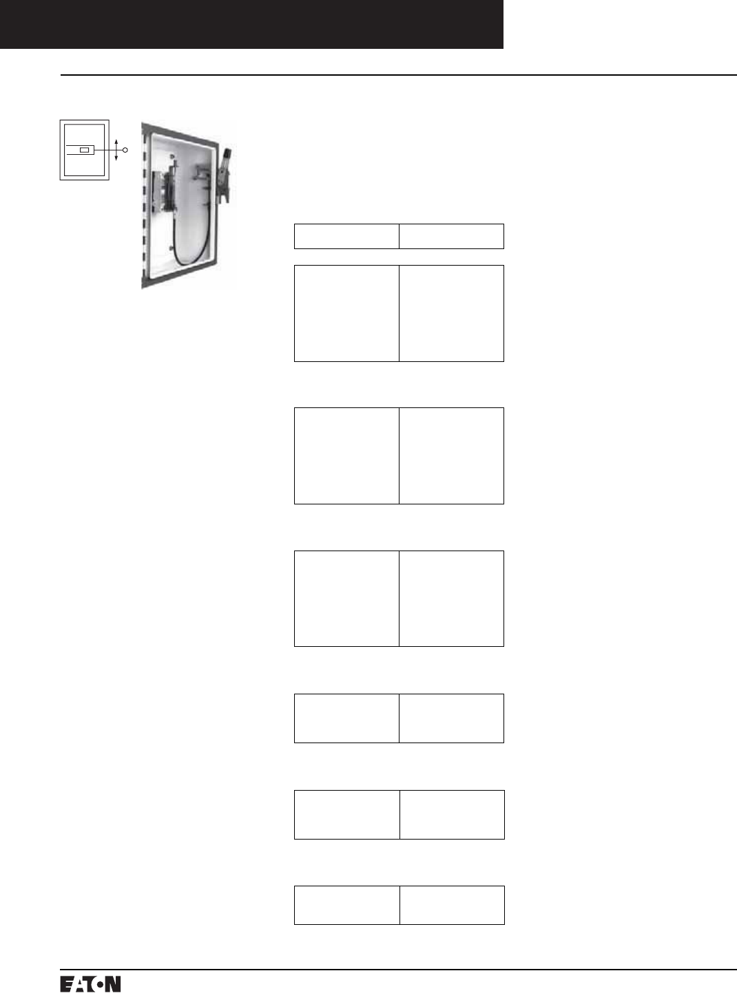
PG.74A.01.T.E
Cutler-Hammer
178 March 1999
Molded Case Circuit Breakers
Series C External Accessories
Handle Mechanisms
Flange Mounted Flex Shaft
The Flex Shaft type handle mecha-
nism is an extra heavy-duty handle
mechanism designed for mounting
in flange-type enclosures. An oper-
ating handle, flexible shaft, and
mechanism are required for
standard application.
The handle can be locked in the
RESET position with up to three
padlocks. The handle is suitable
for Types 1, 3R, 4➀, 4X➀, and 12 fab-
ricated enclosures. The handle fits
the industry standard cutout.
Eight lengths of shafts are available
for use with the wide range of
depths of various enclosures (3 feet
through 10 feet). These choices
enable this mechanism to be
mounted in various depth, width,
and height enclosures.
Note: when selecting the length of
shaft, ensure minimum bending
radius of 4 inches is maintained
to operate properly.
The standard method of shipment
includes the mechanism preset at
the factory; however, minor field
adjustments may be required.
For this publication, the term
Circuit Breaker shall also include
the molded case switch and Series C
motor circuit protector (HMCP).
UL File E64893.
Ordering Information
Catalog Number includes complete
assembly consisting of C371 handle,
flexible shaft, operating mechanism,
and door interlock hardware to fit
industry standard flange cutout.
Length of Flex Shaft
(in feet)
Catalog
Number
F-Frame➁
3
4
5
6
7
8
9
10
F1S03C
F1S04C
F1S05C
F1S06C
F1S07C
F1S08C
F1S09C
F1S10C
Instruction Leaflet/FRED Number 15609
J-Frame➁
3
4
5
6
7
8
9
10
F2S03C
F2S04C
F2S05C
F2S06C
F2S07C
F2S08C
F2S09C
F2S10C
Instruction Leaflet/FRED Number 15605
K-Frame➁
3
4
5
6
7
8
9
10
F3S03C
F3S04C
F3S05C
F3S06C
F3S07C
F3S08C
F3S09C
F3S10C
Instruction Leaflet/FRED Number 15604
L- and M-Frames
4
5
6
10
F4S04
F4S05
F4S06
F4S10
N-Frame
4
5
6
10
F5S04
F5S05
F5S06
F5S10
Instruction Leaflet/FRED Number 15606
R-Frame
4
5
6
F6S04
F6S05
F6S06
Instruction Leaflet/FRED Number 15606
➀Type 4/4X handle mechanisms are available.
Add suffix X to complete catalog number.
➁Add suffix I to complete catalog number for
IEC handle. Add suffix L to complete catalog
number for 6-inch handle.
Instruction Leaflet/FRED Number 15606
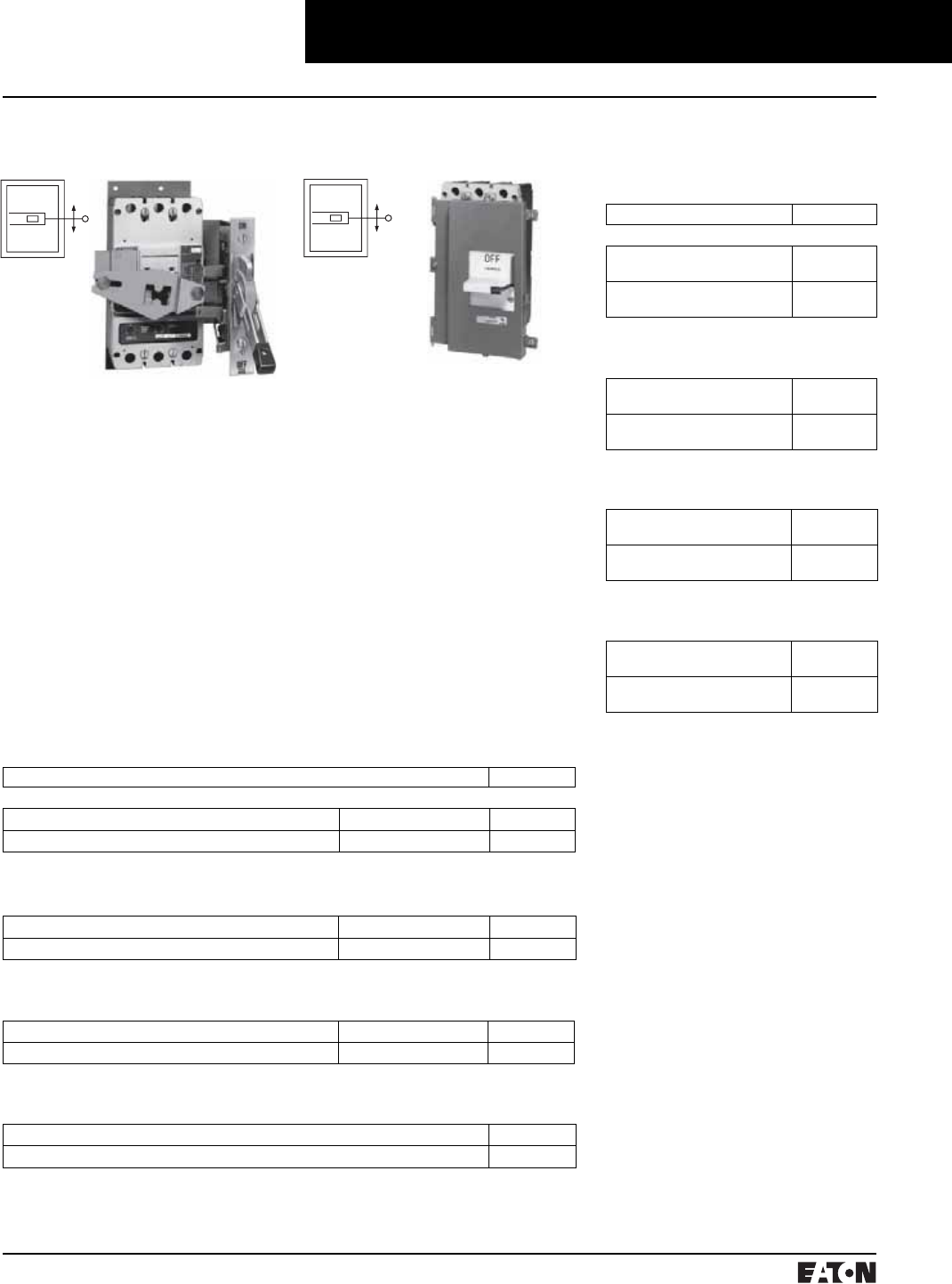
March 1999
PG.74A.01.T.E
Cutler-Hammer 179
Molded Case Circuit Breakers
Series C External Accessories
Handle Mechanisms
Instruction Leaflet/FRED Number 14439
Flange Mounted
Type SM Safety
The SM safety handle mechanism
provides a means of externally oper-
ating a circuit breaker mounted in an
enclosure and is designed to reduce
the possibility of circuit breaker tam-
pering. The handle mechanism is
especially suited for use in automo-
tive and machine tool industries
through its conformance to Type 12
and J. I. C. requirements. A specially
modified handle mechanism for
Type 4 enclosure application is also
available order by description. The
handle mechanism will accept up to
three padlock shackles, each with a
maximum diameter of 3/8 inch
(9.52mm). UL File E64893.
Ordering Information
Description Catalog Number
F-Frame
Right-Hand Mounting Enclosure Cover Hinged on Left SM150R
Left-Hand Mounting Enclosure Cover Hinged on Right SM150L
Instruction Leaflet/FRED Number 29C274
J-Frame
Right-Hand Mounting Enclosure Cover Hinged on Left SM250JR
Left-Hand Mounting Enclosure Cover Hinged on Right SM250JL
Instruction Leaflet/FRED Number 29C274
K-Frame
Right-Hand Mounting Enclosure Cover Hinged on Left SM400KR
Left-Hand Mounting Enclosure Cover Hinged on Right SM400KL
Instruction Leaflet/FRED Number 29C284
L- and M-Frames
Hinged on Left SM600R
Hinged on Right SM600L
➀Width spacer kits cannot be used with short
rod at minimum enclosure depth.
J-Frame
For use with Type 1
Enclosure Catalog
SMCU250JD
For use with Type 12
Enclosure Catalog
CMCU250JD
Through-the-Door
Type MC Motor Control
Instruction Leaflet/FRED Number 14572
The MC motor control handle mecha-
nism is a linear-operating, fixed-
depth mechanism designed for
through-the-door mounting in stan-
dardized and shallow depth enclo-
sures. The handle mechanism pro-
vides positive operation and direct
disconnect status indication. It is
interlocked with the enclosure door
so that the door can be opened only
when the handle is set to OFF.
(A defeater, supplied with the handle
mechanism, can be used to bypass
the interlock for maintenance and
inspection.) The handle mechanism
will accept up to three padlock shack-
les, each with a maximum diameter
of 3/8 inch (7.92 mm).UL File E56845.
Ordering Information
Description Catalog Number
F-Frame
For use with Type 1
Enclosure Catalog
SMCU150FD
For use with Type 12
Enclosure Catalog
CMCU150FD
Instruction Leaflet/FRED Number 29C273
Instruction Leaflet/FRED Number 29C273
K-Frame
For use with Type 1
Enclosure Catalog
SMCU400KD
For use with Type 12
Enclosure Catalog
CMCU400KD
Instruction Leaflet/FRED Number 29C283
M-Frames
For use with Type 1
Enclosure Catalog
SMCU600LD
For use with Type 12
Enclosure Catalog
CMCU600LD
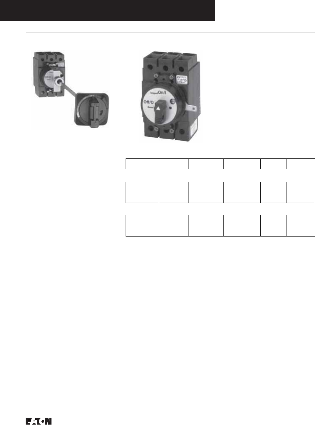
PG.74A.01.T.E
Cutler-Hammer
180 March 1999
Molded Case Circuit Breakers
Series C External Accessories
Handle Mechanisms
Through-the-Door Rotary
These compact rotary handle mech-
anisms are especially designed for
use with the GD/GC/GHC circuit pro-
tection devices. The Close-Coupled
version is designed for mounting in
a shallow enclosure, while the Vari-
Depth is suitable for deep enclosures.
Both G-frame handle mechanisms
are suitable for use on Type 1 enclo-
sures. In addition, the Vari-Depth
handle mechanism is offered for use
with Types 3R, 12, and 4X enclosures.
The new handles are a compact,
plastic, general purpose design
which is easy to install. These mech-
anisms are commonly used where
high volume, standardized enclo-
sures are being fabricated.
The Close-Coupled design is avail-
able with or without a shroud. The
handle is offered in two colors; black
or yellow. An escutcheon ring and
interlock clip are provided as stan-
dard. This standard design includes
a lock-off feature.
The Vari-Depth design includes an
operating mechanism, shaft, and
external handle. The handle is avail-
able in two colors; black or yellow.
An external lock-off is included in
the handle design. The shaft may be
cut to size to fit the enclosure.
UL and CSA listed.
Ordering Information
Breaker
Frame
Enclosure
Type
Handle
Color
Shaft
Length
Shroud
Included
Catalog
Number
G-Frame Vari-Depth Design
(Catalog Number includes complete assembly consisting of handle, shaft, and operating mechanism.)
GD/GC/GHC
GD/GC/GHC
GD/GC/GHC
GD/GC/GHC
Type 1
Type 1
Type 3R/12/4X
Type 3R/12/4X
Black
Yellow
Black
Yellow
14 inches – HRGCV11L
HRGCV31L
HRGCV14L
HRGCV34L
G-Frame Close-Coupled Design
(Catalog Number includes complete assembly consisting of operating handle and door interlock.)
GD/GC/GHC
GD/GC/GHC
GD/GC/GHC
GD/GC/GHC
Type 1
Type 1
Type 1
Type 1
Black
Black
Yellow
Yellow
–No
Yes
No
Yes
HRGCC10
HRGCC1S
HRGCC30
HRGCC3S
Instruction Leaflet/FRED Number 15567 (Close Coupled);
Instruction Leaflet/FRED Number 15569 (Variable Depth)
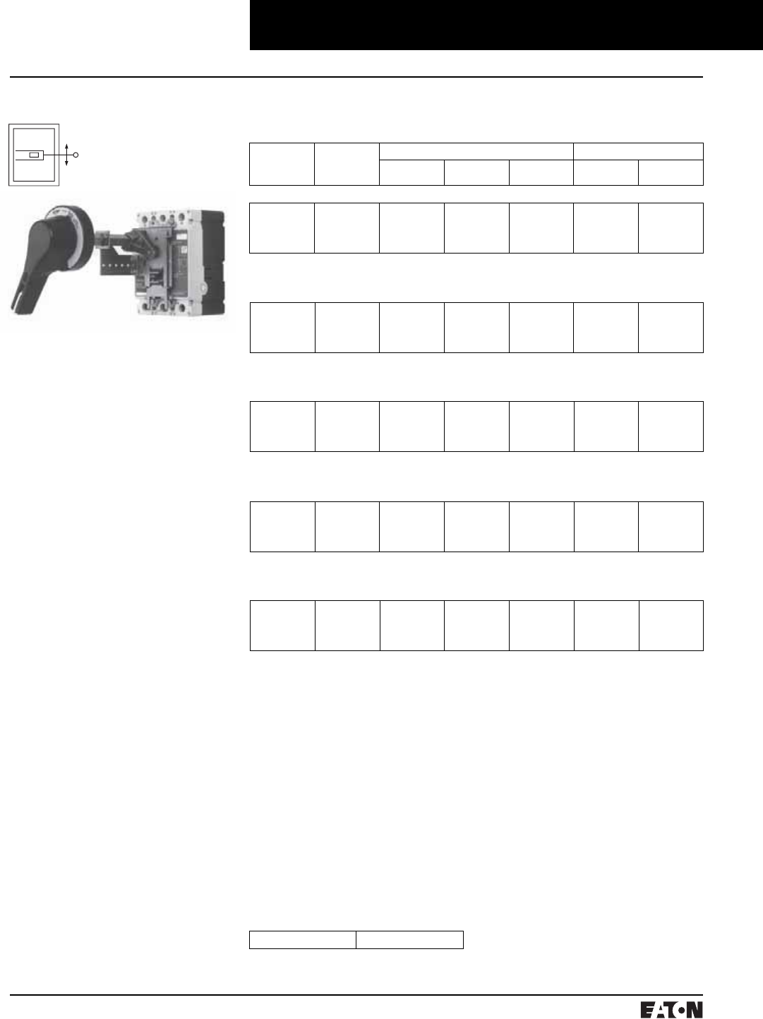
March 1999
PG.74A.01.T.E
Cutler-Hammer 181
Molded Case Circuit Breakers
Series C External Accessories
Handle Mechanisms
Instruction Leaflet/FRED Number 15602
N-Frame
6
12
16
24
HM5R06
HM5R12
HM5R16
HM5R24
6648C22G11
6648C22G11
6648C22G11
6648C22G11
6648C23G07
6648C23G07
6648C23G07
6648C23G07
4217B37G04
4217B37G01
4217B37G02
4217B37G03
WHM5R06
WHM5R12
WHM5R16
WHM5R24
WHM5R06X
WHM5R12X
WHM5R16X
WHM5R24X
Instruction Leaflet/FRED Number 15601
L- and M-Frames
6
12
16
24
HM4R06
HM4R12
HM4R16
HM4R24
6648C22G11
6648C22G11
6648C22G11
6648C22G11
6648C23G07
6648C23G07
6648C23G07
6648C23G07
4217B37G04
4217B37G01
4217B37G02
4217B37G03
WHM4R06
WHM4R12
WHM4R16
WHM4R24
WHM4R06X
WHM4R12X
WHM4R16X
WHM4R24X
Instruction Leaflet/FRED Number 15600
K-Frame
6
12
16
24
HM3R06
HM3R12
HM3R16
HM3R24
6648C22G01
6648C22G01
6648C22G01
6648C22G01
6648C23G13
6648C23G13
6648C23G13
6648C23G13
4217B37G04
4217B37G01
4217B37G02
4217B37G03
WHM3R06
WHM3R12
WHM3R16
WHM3R24
WHM3R06X
WHM3R12X
WHM3R16X
WHM3R24X
Instruction Leaflet/FRED Number 15599
J-Frame
6
12
16
24
HM2R06
HM2R12
HM2R16
HM2R24
6648C22G01
6648C22G01
6648C22G01
6648C22G01
6648C23G02
6648C23G02
6648C23G02
6648C23G02
4217B37G04
4217B37G01
4217B37G02
4217B37G03
WHM2R06
WHM2R12
WHM2R16
WHM2R24
WHM2R06X
WHM2R12X
WHM2R16X
WHM2R24X
Through-the-Door Rotary
The general purpose rotary handle
mechanisms are suitable for use
with Types 1, 3R, (4, 4X), and 12
fabricated enclosures. They are
designed for use with Series C
F-frame circuit breakers, molded
case switches, and motor circuit
protectors (HMCP).
Required for a standard application
are the operating handle, shaft, and
mechanism.
The operating handle has been
designed to meet NFPA 79 require-
ments. It may be mounted in either
the horizontal or the vertical direc-
tion. The handle was ergonomically
designed with extra clearance for a
“gloved hand” to operate. It may be
padlocked in the OFF position utiliz-
ing 3 padlocks.
The standard label on the operating
handle indicates ON/Tripped/OFF/
Reset. UL File E64893
To meet the various enclosure
depths, four variable depth shafts
are offered (6-inch, 12-inch, 16-inch,
and 24-inch). Each shaft includes a
support brace to ensure proper
alignment. In addition, the 16-inch
and 24-inch extra long shafts include
an adjustable support bracket.
The standard mechanism located on
the breaker does include means for
internally locking the breaker in the
“OFF” position with up to three
padlocks each with a maximum
diameter of.312-inch.
Type 4/4X handles are similar to stan-
dard handles except they include an
internal neoprene gasket. Type 4/4X
handle style number is 6648C22G03.
Due to gasketing effect between the
handle and the housing, the handle
may not indicate a tripped position.
Accessories
As an option, an auxiliary switch is
offered so that the control panel
builder may electrically indicate the
status of the breaker. This accessory
would be mounted on the mecha-
nism and comes with 24-inch pigtail
leads.
Instruction Leaflet/FRED Number 15594
Ordering Information
Shaft
Length
(Inches)
Complete
Catalog
Number➀
Separate Style Number Catalog Number
Standard
Handle➂
Breaker
Mechanism➃
Shaft➄IEC IP65➄➅ IEC IP66➄➅
F-Frame
6
12
16
24
HM1R06
HM1R12
HM1R16
HM1R24
6648C22G01
6648C22G01
6648C22G01
6648C22G01
6648C23G11
6648C23G11
6648C23G11
6648C23G11
4217B37G04
4217B37G01
4217B37G02
4217B37G03
WHM1R06
WHM1R12
WHM1R16
WHM1R24
WHM1R06X
WHM1R12X
WHM1R16X
WHM1R24X
Style Number 5108A61G01
Refer to CD-ROM, SA.74A.01.T.E,
for replacement type Vari-depth
and AMT handle mechanisms.
➀Complete catalog number includes the stan-
dard handle, mechanism, shaft, and support
brace/bracket.
➁Handle is designed suitable for Types 1, 3R,
and 12 enclosures. Use style number
6648C22G03 for Type 4/4X handle or add X
suffix to complete catalog number.
➂The standard handle label indicates ON/
Tripped/OFF/Reset.
➂Breaker mechanism includes a shaft support
bracket and its parts.
➃Longer shafts (16-inch and 24-inch) include
an adjustable support extension.
➄IEC Handle Mechanism supplied with Metric
thread mounting hardware.
➅Complete Catalog Number includes a
handle, mechanism and shaft.
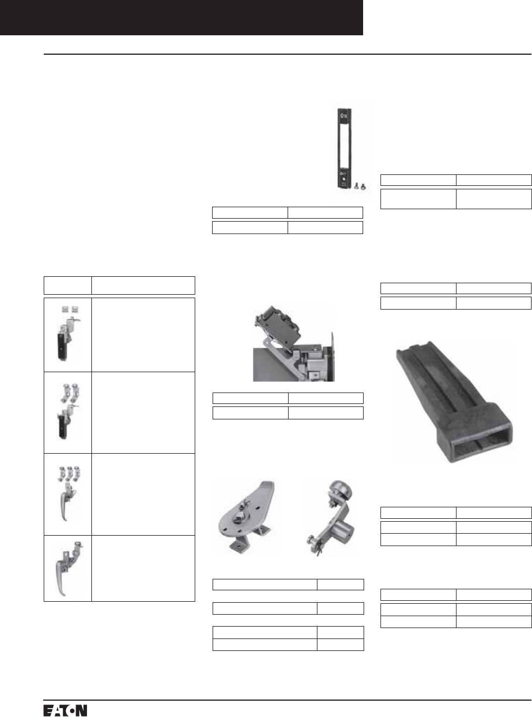
PG.74A.01.T.E
Cutler-Hammer
182 March 1999
Door Operated Interlock Defeater
Kit for Type SM Mechanisms
Required when door hardware is not
used, operates as door closes. Addi-
tional method of securing door such
as screw latch, also required (sup-
plied by box manufacturer).
Door Hardware listed in this section
may be used with Types SM and
AMT handle mechanisms.
Three choices of door hardware and
an auxiliary handle are offered to
provide the best latching scheme for
individual needs. The door hard-
ware is designed with a provision
for padlocking, and a coin-proof slot
that requires the use of a tool to
open the door.
Select desired hardware below.
Additional latches can be ordered
from accessories section if desired.
Molded Case Circuit Breakers
Series C External Accessories
Handle Mechanisms
Description Style Number
Door Operated
Interlock Defeater Kit 623B214G02
Description Style Number
For Door Hardware Using Sliding Latches
Right- or Left-Hand Mounting 622B747G01
For Door Hardware Using Rolling Latches
Right-Hand Mounting 370D801G04
Left-Hand Mounting 370D802G04
Description Style Number
Dress Nameplate 373D260G05
Hardware
Item
Description and
Catalog Number
With sliding latches for smaller
panels up to approx. 30-inch high.
Catalog Number
Right Hand: DH1R
Left Hand: DH1L
Instruction Leaflet/FRED
Number 13327(L); 13326(R)
With 2-roller latches for
intermediate panels up to
approx. 40-inch high.
Catalog Number
Right Hand: DH2R
Left Hand: DH2L
Instruction Leaflet/FRED
Number 13325(L); 13324(R)
With 3-roller latches for larger
panels, approx. 40-inch and
higher.
Catalog Number
Right Hand: DH3R
Left Hand: DH3L
Instruction Leaflet/FRED
Number 13323(L); 13322(R)
Auxiliary handle for larger panels.
Catalog Number
Right Hand: DH4R
Left Hand: DH4L
Door Hardware
F-, J-, K-, L- and M-Frames
Note: Right-hand enclosure cover
hinged on left, left-hand enclosure
cover hinged on right.
Accessories
Dress Nameplates:
Required to meet automo-
tive specifications. Mounts
from inside enclosure and
covers operating mecha-
nism mounting bolts;
makes mechanism non-
removable when enclosure
door is closed.
Description Style Number
Electrical Interlock Kit 622B747G01
Electrical Interlock Kit: Provides 1
N.C. and 1 N.O. contacts (SPDT
switch) for use with auxiliary cir-
cuits. Mounts to end of mechanism
housing as shown.
Auxiliary Latch Kits: Provide an
additional latch for use with applica-
tions where two point latching may
not be adequate.
Sliding Latch Rolling Latch
Description Style Number
Remote Mounting Kit 505C367G01
Remote Mounting Kit (J-Frame)
Enables the operating mechanism to
be mounted remotely on a vertical
centerline from the circuit breaker or
disconnect switch.
Handle Extension
Handle extension is not included with
J-, K-, L-, and M-Frame breakers. It
must be purchased separately.
Handle extension is included with
breaker with N- and R-Frame
breakers.
Frame Catalog Number
J, KHEX3
L, MHEX4
Frame Catalog Number
NHEX5
RHEX6
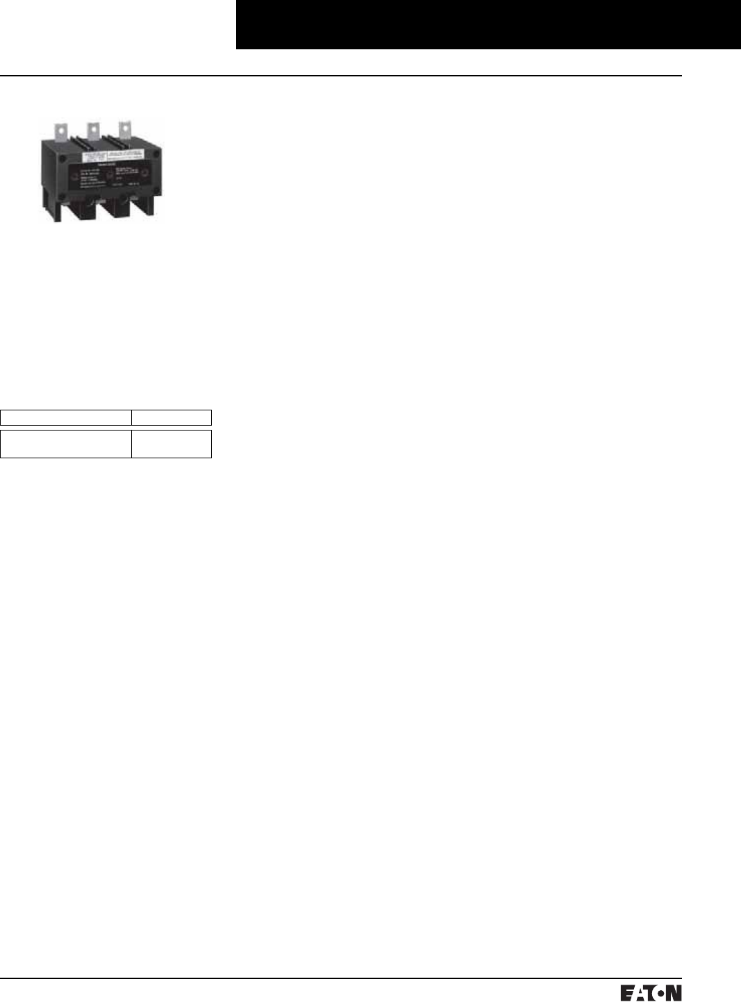
March 1999
PG.74A.01.T.E
Cutler-Hammer 183
Molded Case Circuit Breakers
Series C External Accessories
Current Limiters
Type LFD
The LFD current limiter is an acces-
sory that bolts to the load end of a
standard FDB or FD thermal-mag-
netic circuit breaker, providing
200,000A interrupting capacity at up
to 600 Vac. LFD current limiters for
thermal-magnetic circuit breakers
are listed with Underwriters Labora-
tories, Inc., under File E47239.
Ordering Information
Instruction Leaflet/FRED Number 29C407
Circuit Breaker Rating Amperes➀Catalog Number
15-70
80-160
LFD3070R
LFD3150R
➀Underwriters Laboratories Inc. listed under
UL File E64983.
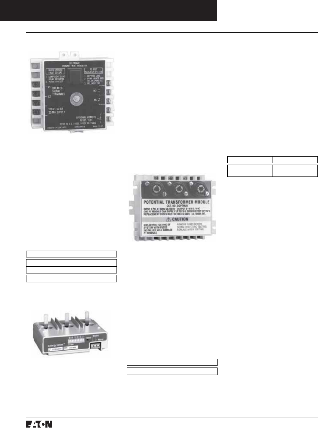
PG.74A.01.T.E
Cutler-Hammer
184 March 1999
Molded Case Circuit Breaker
Series C External Accessories
Instruction Leaflet/FRED Number 29C614 Diagram
Ordering Information
Catalog Number
GFAU – Ground Fault Alarm Unit
Style Number
1264C67G01 – Face Mounting Bracket
Instruction Leaflet/FRED Number 29C894 Diagram
Ordering Information
Description Catalog Number
Potential Transformer Module DOPTMLN
Ground Fault Alarm Unit
Potential Transformer Module
The Ground Fault Alarm Unit is a
remotely mounted device with a
combination indicating light/test
button that will light when the
breaker trips or alarms on ground
fault. The Ground Fault Alarm Unit
requires a separate 120 Vac power
source to power the light and the
internal relay which has 1 N.O. and
1 N.C. contacts for remote indica-
tion. The Ground Fault Alarm Unit
can be panel mounted for ordering
with an optional face mounting
bracket. For use on Digitrip 310 only.
K- through N-frame.
The Potential Transformer Module is
required for Series C, Digitrip OPTIM
1050, to provide a voltage input to
allow the trip unit to monitor power
and energy as well as power factor.
The Potential Transformer Module is
a 6 VA transformer with a primary
voltage input of up to 600V line to
line. Three 0.1 ampere fuses are pro-
vided on the primary of the trans-
former and can be used for isolation
purposes during dielectric testing.
The device is normally panel
mounted and can feed up to 16
OPTIM trip units.
➀Model 550 OPTIMs require the Cutler-Hammer
PowerNet field upgrade kit.
IQ Energy Sentinel
The IQ Energy Sentinel is a highly
accurate, microprocessor-based,
breaker-mounted device designed to
Solid-State (Electronic)
Portable Test Kit
The solid-state (electronic) portable
test kit provides verification of per-
formance of all ratings of Digitrip
310 electronic trip units installed in
Series C circuit breakers while in
service under varying load and/or
phase imbalance. The test kit oper-
ates on 120-volt, 50/60 Hz power; it
includes complete instructions and
test times for testing long time,
short time/instantaneous operation
and optional ground fault operation
of the circuit breaker.
Ordering Information
Description Catalog Number
Solid-State (Electronic)
Portable Test Kit STK2
monitor power and energy readings.
It represents an alternative to watt
meters, watt-hour meters, and watt
demand meters. Key advantages
include savings in space, lower
installation costs, and remote moni-
toring capability.
The IQ Energy Sentinel mounts on
the load side of a Series C F-frame
(150 ampere) circuit breaker. It can
be applied on three-phase, four-wire
systems, or single-phase, three-wire
systems with voltage connected
through phases A and C.
Instruction Leaflet/FRED Number 17437
For more information see
Descriptive Bulletin 8178.
March 1999
PG.74A.01.T.E
Cutler-Hammer 185
Cutler-Hammer PowerNet
Software
Auxiliary Power Module
The Auxiliary Power Module is a
power supply requiring 120 Vac
input at 50 or 60 Hz that provides a
32 Vdc output➀. The Auxiliary Power
Module provides control power for
testing an OPTIM trip unit when
other means of control power is not
available or for continuous OPTIMizer
operation versus temporary with a
battery. The Auxiliary Power Module
connects into the top of the Digitrip
OPTIMizer via a keyed receptacle.
The main application for the Auxil-
iary Power Module would be for the
testing of a stand-alone non-commu-
nicating OPTIM breaker that ordi-
narily would not have control power.
Ordering Information
Catalog Number
PRTAAPM
Molded Case Circuit Breakers
Series C External Accessories
OPTIM System Components
Series C Digitrip OPTIM trip units
can communicate back to a central
Personal Computer by installing
Cutler-Hammer PowerNet software➁.
In addition other software packages
are available to allow the user to
configure the trip units as well as
monitor system performance.
Instruction Leaflet/FRED Number 29C890
Instruction Leaflet/FRED Number 29C893
Ordering Information
Catalog Number
BIM
Instruction Leaflet/FRED Number 29C892
Ordering Information
Catalog Number
OPTIMizer – Standard Package
The Breaker Interface Module (BIM)
is a panel mounted user interface
device that is mounted on the front
of an electrical assembly or at a
remote location. The BIM is used to
access, configure, test and display
information for OPTIM trip units and
other devices. The BIM consists of
four display windows, eight function
buttons, 18 LEDs, and a graphical
time/current curve to provide
breaker status, operational informa-
tion, protection status and energy
monitoring. A 24 Vdc power supply
is required to provide power to the
BIM. This is supplied by the switch-
board builder to Cutler-Hammer
specifications. The BIM is a member
of the Cutler-Hammer PowerNet
family of communicating devices
that connects OPTIM trip units,
Digitrip RMS 810/910 trip units and
energy sentinels as a subnetwork
system. The BIM can also be con-
nected to a main network via a PONI
module to Cutler-Hammer PowerNet
software.
Breaker Interface Module
(BIM)
Digitrip OPTIMizer
The Digitrip OPTIMizer is a hand-
held programmer that is used to
access, configure, test and display
information from OPTIM trip units.
The OPTIMizer plugs into the front
of an OPTIM trip unit via an eight-
pin telephone jack and is powered
by a nine-volt battery or the auxil-
iary power module. In addition,
a three-pin INCOM network connec-
tion is also provided to program
other OPTIM devices on the system.
An Auxiliary Power Module connec-
tion provides a trip test when con-
trol power is not present at the
breaker. The OPTIMizer is supplied
as a standard package to include the
programmer, the eight-pin connec-
tion cord, battery and carrying case.
The Auxiliary Power Module is
optional.
Note: 24 Vdc Power Supply
A 24 Vdc power supply is required for all Digitrip
OPTIM trip units that are required to communi-
cate either on the main Cutler-Hammer PowerNet
network or as a subnetwork to a BIM. The break-
er’s load is 45 mA of current. Typically one power
supply is required per switchboard and can pro-
vide control power to a BIM and the OPTIM trip
units. The 24 Vdc power supply should be an
“isolated high quality” power supply with a
“CE” label, and is normally provided by the
switchboard manufacturer to Cutler-Hammer
recommendations.
➀The OPTIMizer can work off of 32 Vdc control
power, although 24 Vdc is the standard on
OPTIM breakers.
➁Model 550 OPTIMS require the Cutler-Hammer
PowerNet field upgrade kit.

PG.74A.01.T.E
Cutler-Hammer
186 March 1999
Molded Case Circuit Breakers
Special Modifications
Special Calibration➀
Special non-UL-listed calibrations
are available for certain ambient
temperatures other than 40°C and
for frequencies other than 50/60 Hz
or Dc. Reduced interrupting ratings
will apply for 400 Hz applications.
Maximum thermal calibration is
limited to 135A at 400 Hz.
See Application Data 29-160 for
information regarding special
conditions.
50°C Calibration➀
Add suffix “V” to catalog number
for complete breaker, listed above,
when ordering listed ampere ratings
for breakers to be used in 50°C
ambients.
Suffix H01 400 Hz.
Moisture-Fungus Treatment
All Series C circuit breaker cases are
molded from glass-polyester which
does not support the growth of fun-
gus. Any parts which are susceptible
to the growth of fungus will require
special treatment.
Freeze-Tested Circuit
Breakers
The circuit breakers may be ordered
with freeze testing. This option uses
special lubrication and mechanical
operation is verified at -40°C.
Suffix J01 Fungus Treated
Suffix F01 Freeze Tested.
Marine Applications
F-Frame circuit breakers can be sup-
plied to meet the following marine
specifications:
U.S. Coast Guard CFR 46 ABS –
American Bureau of Shipping
IEEE 45
These specifications generally
require molded case circuit breakers
to be supplied with 50°C ambient
calibration, special nameplating,
and plug-in adapter kits. When plug-
in adapter kits are used, no termi-
nals need be supplied.
Series C circuit breakers can also be
supplied to meet UL489 Supplement
SA (Marine Use) and UL489 Supple-
ment SB (Naval Use).
UL489 Supplement SA applies to
vessels over 65 feet in length.
Requirements include 40°C ambient
calibration, special labeling, and
no use of aluminum conductors or
terminals.
UL489 Supplement SB requires 50°C
ambient calibration, vibration test-
ings, special nameplating and no
use of aluminum conductors or
terminals.
Suffix H08 “Marine.”
Suffix H09 “Naval.”
➀Not listed with Underwriters Laboratories,
Inc.
➁For use with standard 35 mm DIN rail such
as, 35 x 7.5 or 15 mm per DIN EN50022.
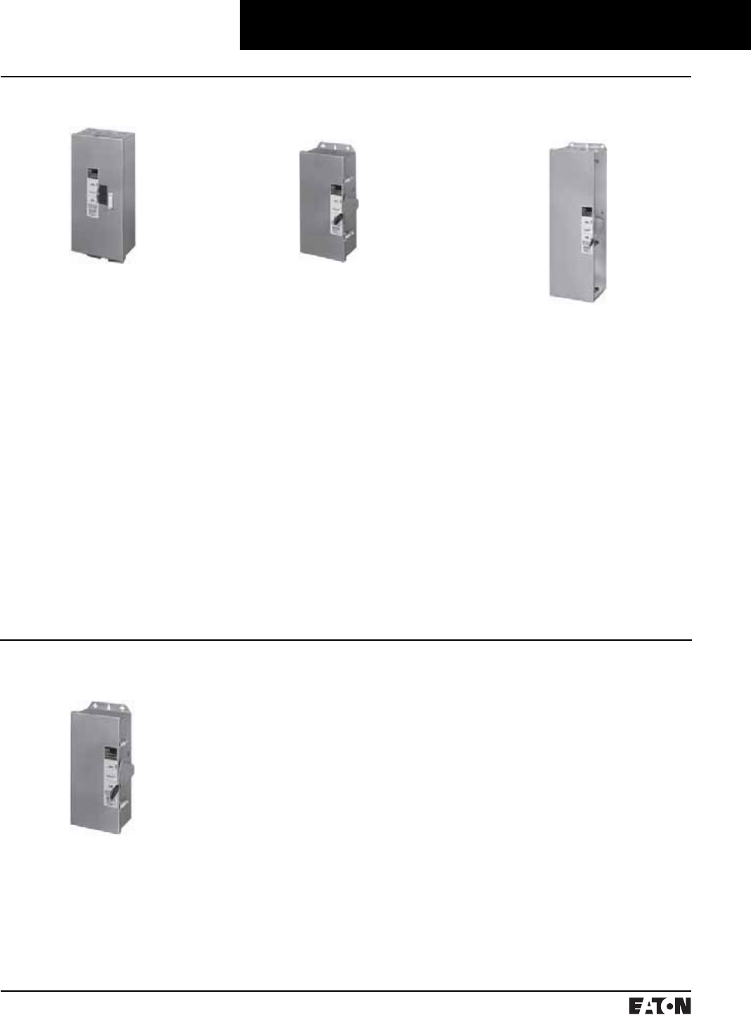
March 1999
PG.74A.01.T.E
Cutler-Hammer 187
Molded Case Circuit Breakers
Enclosures
NEMA 7, 9 Hazardous
Location
Cast Aluminum, Explosionproof
Surface Mounting
15-800 Ampere Range
600 Volts Ac, 250 Volts Dc
Hazardous location, Class I, Groups B
(except XFDN050), C, D; Class II,
Groups E, F, G. This special service
cast aluminum enclosure is supplied
with a wide, machined flanged cover
to prevent igniting outside atmo-
spheres by arcing from inside the
enclosure. Front operable, the handle
padlocks in the Off position. Enclo-
sures rated 600 amperes and above
have lift-off hinges for ease of assem-
bly. UL and cUL File Number E71279.
NEMA 3R Rainproof
Surface Mounting
NEMA 4/4X, 5 Water
and Dustproof
NEMA 12 Dustproof
Surface Mounting
NEMA 1 General Purpose
No Knockouts or Other Openings
15-1200 Ampere Range
600 Volts Ac, 500 Volts Dc
The Type 12 enclosure is designed in
line with specifications for special
industry application where unusually
Surface or Flush Mounting
15-1200 Ampere Range
600 Volts Ac, 500 Volts Dc
NEMA 1 enclosed breakers are
designed for indoor use in commer-
cial buildings, apartment buildings
and other areas where a general pur-
pose enclosure is applicable. The
breaker is front operable and is capa-
ble of being padlocked in the Off
position. (Padlocking not available
on enclosures for Quicklag break-
ers.) Ratings through 1200 amperes
are listed with Underwriters Labora-
tories, Inc. as suitable for service
entrance application. Both surface
and flush mounted enclosures are
available. UL File Number E7819.
CSA File Number LR84319.
Interchangeable Hubs (through
400 amperes)15-1200 Ampere Range
600 Volts Ac, 500 Volts Dc
This general purpose outdoor ser-
vice center employs a circuit breaker
inside a weatherproof sheet steel
enclosure to serve as a main discon-
nect and protective device for feeder
circuits. The operating handle can be
padlocked in the Off position, and is
interlocked to prevent the door from
opening when the breaker is On. Rat-
ings through 1200 amperes are
listed by Underwriters Laboratories,
Inc. as suitable for service entrance
application. UL File Number E7819.
CSA File Number LR84319.
Stainless Steel – Type 304
Surface Mounting
15-1200 Ampere Range
600 Volts Ac, 500 Volts Dc
This enclosure meets NEMA 4/4X
and 5 requirements for water and
dustproof applications and has no
knockouts or other openings. It is
particularly well suited for use in
dairies, borax mines, breweries,
paper mills and other process indus-
tries. The operating handle can be
padlocked in the Off position, and is
interlocked to prevent the door from
opening when the breaker is On.
Ratings through 1200 amperes are
Underwriters Laboratories, Inc. listed
as suitable for service entrance
application. UL File Number E7819.
CSA File Number LR84319.
severe conditions involving oil, cool-
ant, dust and other foreign materials
exist in the operating atmosphere.
The handle padlocks in the Off posi-
tion and the cover is interlocked with
the handle mechanism to prevent
opening the cover with the circuit
breaker in the On position. Ratings
through 1200 amperes are listed by
Underwriters Laboratories, Inc. as
suitable for service entrance applica-
tion. A NEMA 12 semi-dust-tight
design which includes knockouts
is available. These units are rated
15-400 amperes, 600 volts Ac, 500
volts Dc. UL File Number E7819.
CSA File Number LR84319.
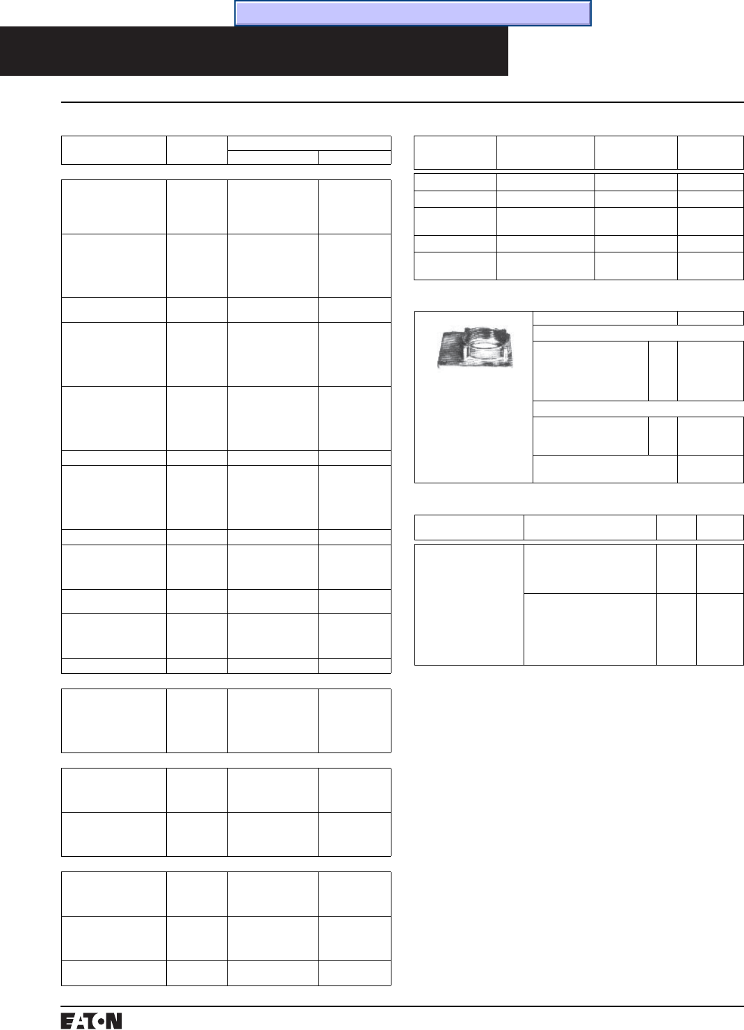
PG.74A.01.T.E
Cutler-Hammer
188 March 1999
Molded Case Circuit Breakers
Enclosures
Raintight Hubs
All rainproof enclosures
30A through 400A are
shipped with plate over
cutout. Hubs are not
supplied with screws
on 30A through 400A
enclosures. Use screws
from plate.
Hub Diameter in Inches Catalog Number
Small Hubs
For use with RGDN
and RFDN
3⁄4
1
1-1⁄4
1-1⁄2
2
DS075H1
DS100H1
DS125H1
DS150H1
DS200H1
Large Hubs
For use with RJDN.
(RKDN has two cutouts)
2
2-1⁄2
3
R1H200
R1H250
R1H300
Required if using Type DS hubs
on RJDN and RKDN enclosures.
R1HA
➀Enclosures only shown above; if an assembled enclosed
circuit breaker is required refer to Cutler-Hammer Satellite.
➁Suitable for use with one-pole breaker base mounting plate kit.
QCCBP required.
➂Enclosure must have date stamp later than 4-15-98.
➃Maximum wire size: 4/0.
➄Availability to be announced.
➅LCL requires additional adapter plate 1223C06G01.
➆LA-P requires additional adapter plate S/N 1223C06G02.
➇If ground fault protection is required, contact regional satellite.
Enclosure Only Catalog Numbers Selection Guide➀
Breaker Frame Breaker
Ampere Range
Enclosure
NEMA Class Catalog Number
Series C Breakers
GC, GHC, GD
2- and 3-Pole only
GHCGFEP➁
1-Pole Only
15-100 1 Surface
3R
12
12K
4/4X, 5 St. Steel
SGDN100➁
RGDN100
JGDN100
DGDN100
WGDN100
EHD, FD, FDB,
HFD, FDC
15-100 1 Surface
1 Flush
3R
12
12K
4/4X, 5 St. Steel
SFDN100
FFDN100
RFDN100
JFDN100
DFDN100
WFDN100
EHD, FD, FDB
HFD, FDC
15-50
60-225➃
7/9 Cast Aluminum
7/9 Cast Aluminum
XFDN050
XFDN225
FD, FDB, HFD, FDC,
ED, EDH, EDC
125-225 1 Surface
1 Flush
3R
12
12K
4/4X, 5 St. Steel
SFDN225
FFDN225
RFDN225
JFDN225
DFDN225
WFDN225
JD, JDB, HJD, JDC 125-250 1 Surface
1 Flush
3R
12
12K
4/4X, 5 St. Steel
SJDN250
FJDN250
RJDN250
JJDN250
DJDN250
WJDN250
JD, JDB, HJD, JDC 125-250 7/9 Cast Aluminum XJDN250
KD, KDB, HKD, KDC, DK 125-400 1 Surface
1 Flush
3R
12
12K
4/4X, 5 St. Steel
SKDN400
FKDN400
RKDN400
JKDN400
DKDN400
WKDN400
KD, KDB, HKD, KDC, DK 125-400 7/9 Cast Aluminum XKDN400
LD, LDB, HLD, LDC 300-600 1 Surface
3R
12
4/4X, 5 St. Steel
SLDN600
RLDN600
JLDN600
WLDN600
LD, LDB, HLD, LDC
MD, MDS
300-600
400-800
7/9 Cast Aluminum XMCN800
MD, MDS, ND, NDC,
HND
400-1200 1 Surface
3R
12
4/4X, 5 St. Steel
SNDN1200
RNDN1200
JNDN1200
WNDN1200
ND, HND, NDC 7/9 Cast Aluminum XNDN1200
Earth Leakage Breakers➄
ELFD, ELHFD and ELFDC
(3-Pole Only)
15-100 1 Surface
1 Flush
3R
12
12K
4/4X
SFD100E
FFD100E
RFDN100E
JFDN100E
DFDN100E
WFDN100E
Current Limit-R Breakers
FCL 15-100 3R
12
12K
4/4X, 5 St. Steel
RFDN150
JFDN150
DFDN150
WFDN150
LCL➅125-400 1 Surface
3R
12
4/4X, 5 St. Steel
SNDN1200
RNDN1200
JNDN1200
WNDN1200
TRI-PAC Breakers
FB-P 15-100 3R
12
12K
4/4X, 5 St. Steel
RFDN150
JFDN150
DFDN150
WFDN150
LA-P➆ 70-400 1 Surface
3R
12
4/4X
SNDN1200
RNDN1200
JNDN1200
WNDN1200
NB-P 500-800 12
4/4X, 5 St. Steel
JNDPN800
WNDPN800
Neutral Kits, Insulated and Groundable➇
Maximum
Enclosure Rating
(Amperes)
Main Lug Size
Cu/Al
Ground Lug Size
Cu/Al
Catalog
Number
100 (1) 14–1/0 (1) 14–1/0 INK100
250 (1) 6–350 kcmil (1) 4–300 kcmil INK250
400 (1) 4–750 kcmil or
(2) 1/0–250 kcmil
(1) 4–300 kcmil INK400
600 (2) 250–500 kcmil (1) 4–300 kcmil INK600
1200 (3) 1/0 to 750 kcmil or
(4) 1/0 to 750 kcmil
(1) #6–250 kcmil INK1200
Breather and Drain, Hazardous Enclosures➄
Description Compliance Conduit
Opening
Catalog
Number
A Universal Breather/
Drain Fitting is installed
in the top of an enclo-
sure to provide ventila-
tion to minimize
condensation and in the
bottom to allow drainage
of accumulated conden-
sation while maintaining
explosion proof integrity.
Type BD:
NEMA 7 – Class I, Groups
C, D; Class I, Zone 1, Group IIB
NEMA 9 – Class II, Groups F, G
1/2 XPBD2
Type DBB:
NEMA 7 – Class I, Groups B,
C, D; Class I, Zone 1, Group IIB
+ Hydrogen
NEMA 9 – Class II, Groups E,
F, G
1/2 XPDBB50
Time/Current Curves, Dimension Sheets, Application Data
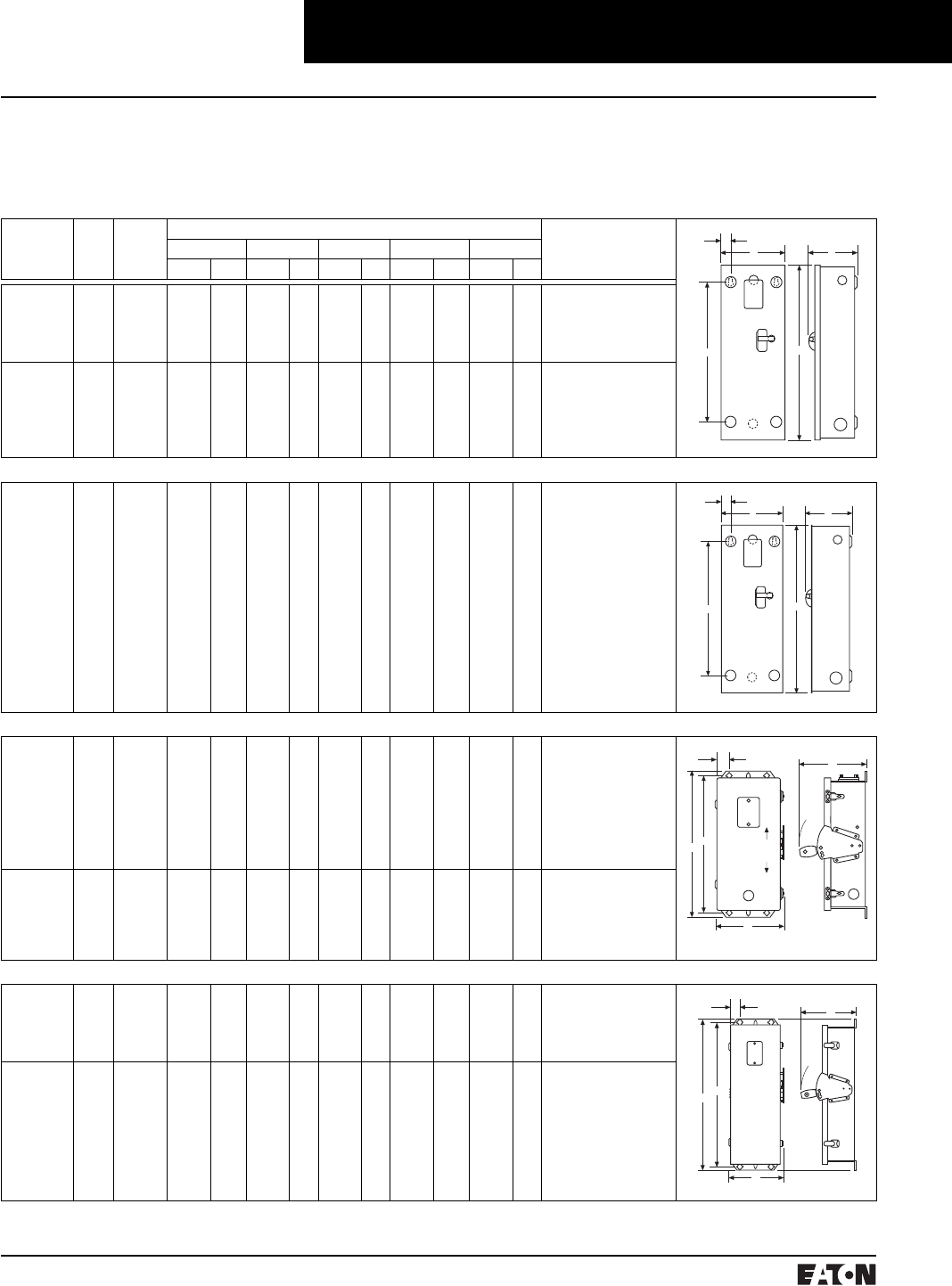
March 1999
PG.74A.01.T.E
Cutler-Hammer 189
Dimensions and Shipping Weights
Not to be used for construction purposes unless approved.
Inches and Millimeters.
NEMA 1 Surface Mounted
Catalog
Number
App.
Wt.
Lbs.
Max.
Amperes
Dimensions Conduit Sizes, Inches
ABCDE
Inches mm Inches mm Inches mm Inches mm Inches mm
SGDN100
SFDN100
SFDN150
SFDN225
SJDN250
12
12
15
15
31
100
100
150
225
250
171⁄2
171⁄2
231⁄4
231⁄4
3445⁄64
444
444
591
591
881
813⁄32
813⁄32
813⁄32
813⁄32
1059⁄64
214
214
214
214
227
69⁄32
69⁄32
69⁄32
69⁄32
713⁄64
160
160
160
160
183
131⁄32
131⁄32
183⁄4
183⁄4
30
331
331
476
476
762
113⁄64
113⁄64
113⁄64
113⁄64
17⁄8
31
31
31
31
48
1⁄4, 1⁄2, 3⁄4, 1, 11⁄4, 11⁄2, 2, 21⁄2
1⁄4, 1⁄2, 3⁄4, 1, 11⁄4, 11⁄2, 2, 21⁄2
1⁄4, 1⁄2, 3⁄4, 1, 11⁄4, 11⁄2, 2, 21⁄2
1⁄4, 1⁄2, 3⁄4, 1, 11⁄4, 11⁄2, 2, 21⁄2
1⁄4, 1⁄2, 2, 21⁄2, 3
SKDN400
SLDN600
SNDN1200
53
81
178
400
600
1200
3813⁄16
457⁄8
617⁄32
986
1165
1555
111⁄16
145⁄16
217⁄16
281
364
545
1015⁄16
123⁄8
1513⁄32
278
314
391
34
469⁄16
6127⁄32
869
1183
1571
29⁄32
129⁄32
131⁄32
58
48
50
1⁄4, 1⁄2, 3⁄4, 11⁄2, 2, 21⁄2, 3, 31⁄2
1⁄4, 1⁄2, 3⁄4, 3, 31⁄2, 4
NEMA 1 Flush Mounted
FFDN100
FFDN150
FFDN225
FJDN250
FKDN400
12
15
15
32
53
100
150
225
250
400
1813⁄16
249⁄16
249⁄16
361⁄64
401⁄8
478
624
624
915
1019
923⁄32
923⁄32
923⁄32
1215⁄64
123⁄8
247
247
247
311
314
69⁄32
69⁄32
69⁄32
713⁄64
1015⁄16
160
160
160
183
278
131⁄32
183⁄4
183⁄4
30
34
331
476
476
762
869
155⁄64
155⁄64
155⁄64
17⁄8
215⁄16
47
47
47
48
75
1⁄4, 1⁄2, 3⁄4, 1, 11⁄4, 11⁄2, 2, 21⁄2
1⁄4, 1⁄2, 3⁄4, 1, 11⁄4, 11⁄2, 2, 21⁄2
1⁄4, 1⁄2, 3⁄4, 1, 11⁄4, 11⁄2, 2, 21⁄2
1⁄4, 1⁄2, 2, 21⁄2, 3
1⁄4, 1⁄2, 3⁄4, 11⁄2, 2, 21⁄2, 3, 31⁄2
NEMA 12, 12K Dustproof
JGDN100
JFDN100
JFDN150
JFDN225
JJDN250
JKDN400
JLDN600
JNDPN800
JNDN1200
14
14
18
18
37
58
81
110
170
100
100
150
225
250
400
600
800
1200
1929⁄32
1929⁄32
2521⁄32
2521⁄32
3717⁄32
4111⁄16
485⁄16
6319⁄32
6319⁄32
506
506
652
652
953
1059
1227
1545
1545
827⁄32
827⁄32
827⁄32
827⁄32
119⁄16
113⁄4
1429⁄32
22
22
225
225
225
225
294
298
379
559
559
95⁄16
95⁄16
95⁄16
95⁄16
107⁄32
141⁄16
151⁄2
175⁄8
175⁄8
237
237
237
237
260
357
394
448
448
1817⁄32
1817⁄32
249⁄32
249⁄32
3549⁄64
3915⁄16
469⁄16
–
6127⁄32
471
471
617
617
909
1014
1183
–
1571
145⁄64
145⁄64
145⁄64
145⁄64
115⁄16
131⁄32
159⁄64
–
131⁄32
43
43
43
43
49
150
49
–
50
DGDN100
DFDN100
DFDN150
DFDN225
DJDN250
DKDN400
16
16
19
19
36
53
100
100
150
225
250
400
1929⁄32
1929⁄32
2521⁄32
2521⁄32
3717⁄32
4111⁄16
506
506
652
652
953
1059
827⁄32
827⁄32
827⁄32
827⁄32
119⁄16
113⁄4
225
225
225
225
294
298
95⁄16
95⁄16
95⁄16
95⁄16
107⁄32
141⁄16
237
237
237
237
260
357
–
–
–
–
–
–
–
–
–
–
–
–
–
–
–
–
–
–
–
–
1⁄4, 1⁄2, 3⁄4, 1, 11⁄4,11⁄2, 2, 21⁄2
1⁄4, 1⁄2, 3⁄4, 1, 11⁄4,11⁄2, 2, 21⁄2
1⁄4, 1⁄2, 3⁄4, 1, 11⁄4,11⁄2, 2, 21⁄2
1⁄4, 1⁄2, 3⁄4, 1, 11⁄4,11⁄2, 2, 21⁄2
1⁄4, 1⁄2, 2, 21⁄2, 3
1⁄4, 1⁄2, 3⁄4, 11⁄2, 2, 21⁄2, 3, 31⁄2
NEMA 3R Rainproof
RGDN100
RFDN100
RFDN150
RFDN225
RJDN250
14
14
19
19
40
100
100
150
225
250
1929⁄32
1929⁄32
2521⁄32
2521⁄32
371⁄2
458
458
603
603
891
827⁄32
827⁄32
827⁄32
827⁄32
119⁄16
225
225
225
225
294
95⁄16
95⁄16
95⁄16
95⁄16
107⁄32
237
237
237
237
260
1817⁄32
1817⁄32
249⁄32
249⁄32
3549⁄64
471
471
617
617
909
145⁄64
145⁄64
145⁄64
145⁄64
115⁄16
43
43
43
43
49
1⁄4, 1⁄2, 3⁄4, 1, 11⁄4, 2, 21⁄2
1⁄4, 1⁄2, 3⁄4, 1, 11⁄4, 2, 21⁄2
1⁄4, 1⁄2, 3⁄4, 1, 11⁄4, 2, 21⁄2
1⁄4, 1⁄2, 3⁄4, 1, 11⁄4, 2, 21⁄2
1⁄4, 1⁄2, 2, 21⁄2, 3
RKDN400
RLDN600
RNDN1200
60
84
175
400
600
1200
4111⁄16
485⁄16
6319⁄32
997
1227
1615
113⁄4
1429⁄32
22
298
379
559
141⁄16
151⁄2
175⁄8
357
394
448
3915⁄16
469⁄16
6127⁄32
1014
1183
1571
131⁄32
159⁄64
131⁄32
50
49
50
1⁄4, 1⁄2, 3⁄4, 21⁄2, 3, 31⁄2
1⁄4, 1⁄2, 3⁄4, 3, 31⁄2, 4
Molded Case Circuit Breakers
Enclosures
E
DA
C
B
D
E
BC
A
ON
OFF
EC
AD
B
C
ON
OFF
E
AD
B
(Continued)
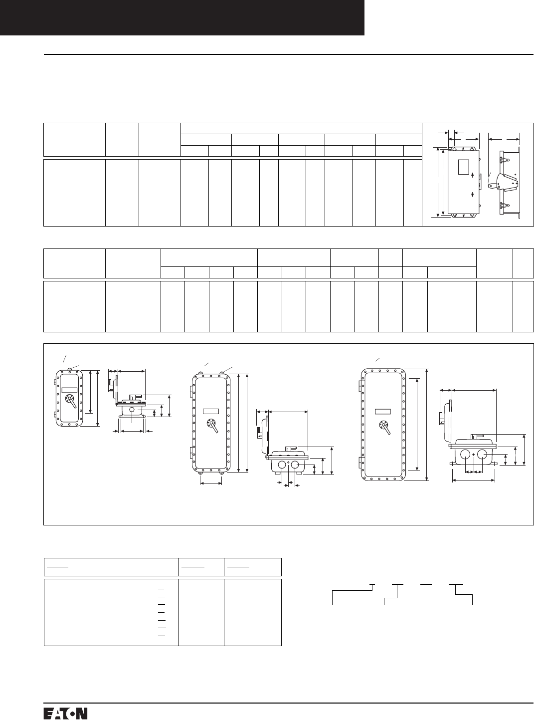
PG.74A.01.T.E
Cutler-Hammer
190 March 1999
Molded Case Circuit Breakers
Enclosures
123G-MTG.
HOLES (3)
8 7 6
F-MTG.
A
CONDUIT POSITION NO.
E-MTG.
11
JB
I
D
C
CONDUIT POSITION NO.
123G-MTG.
HOLES (4)
F-MTG.
A
E-MTG.
8 7 6
I
D
C
JB
H
H
CONDUIT POSITION NO.
123
G-MTG.
HOLES (4)
F-MTG.
A
8 7 6
I
D
C
JB
HH
E-MT
Dimensions and Shipping Weights
Not to be used for construction purposes unless approved.
Inches and Millimeters.
NEMA 4/4X, 5 Stainless Steel
Catalog
Number
App.
Wt.
Lbs.
Max.
Amperes
Dimensions
ABCDE
Inches mm Inches mm Inches mm Inches mm Inches mm
WGDN100
WFDN100
WFDN150
WFDN225
WJDN250
WKDN400
WLDN600
WNDN1200
16
16
20
20
39
60
88
185
100
100
150
225
250
400
600
1200
1929⁄32
1929⁄32
2521⁄32
2521⁄32
371⁄2
4111⁄16
485⁄16
6319⁄32
506
506
652
652
953
1059
1227
1545
827⁄32
827⁄32
827⁄32
827⁄32
119⁄16
113⁄4
1429⁄32
22
225
225
225
225
294
298
379
559
95⁄16
95⁄16
95⁄16
95⁄16
107⁄32
141⁄16
151⁄2
175⁄8
237
237
237
237
260
357
394
448
1817⁄32
1817⁄32
249⁄32
249⁄32
3549⁄64
3915⁄16
469⁄16
6127⁄32
471
471
617
617
909
1014
1183
1571
145⁄64
145⁄64
145⁄64
145⁄64
115⁄16
131⁄32
159⁄64
131⁄32
43
43
43
43
49
50
49
50
E
B
D
AON
OFF
C
NEMA 4/4X, 5 Stainless Steel
Catalog
Number
Breaker
Size
(Amperes)
Overall
Enclosure
Enclosure
Mounting
Conduit Hinged
Cover
Standard
Conduit
Weight
(lbs.)
Dia.
No.
A B C D E F G H I J Size Location
XFDN050
XFDN225
XJDN250
XKDN400
XMCN800
XNDN1200
50
100/225
250
400
600/800
1200➀
15
251⁄2
381⁄2
443⁄4
503⁄4
65
105⁄8
121⁄2
13
18
203⁄4
25
83⁄4
101⁄8
111⁄4
123⁄8
15
151⁄4
513⁄16
75⁄8
83⁄4
97⁄8
121⁄2
123⁄4
9
101⁄2
111⁄2
10
22
231⁄2
12
20
28
45
40
50
1⁄2
1⁄2
1⁄2
1⁄2
1⁄2
1⁄2
13⁄4
2
21⁄8
3
4
61⁄2
31⁄4
31⁄4
31⁄2
4
5
43⁄4
25⁄8
43⁄4
51⁄2
51⁄2
6
7
11⁄4
2
21⁄2
3
4
4
2 & 7
2 & 7
2 & 7
1, 3 & 6, 8
1, 3 & 6, 8
1, 3 & 6, 8
34
70
120
180
460
600
1
1
1
2
3
3
Conduit Openings
Refer to outline dimensions for size and
location of standard conduit openings.
In addition, 1⁄2-inch openings are drilled
and tapped for breather and drain. Unless
ordered with breather and drain, these
openings are plugged. Refer to Cutler-
Hammer for list price of breather and
drain.
Diagram 1
Diagram 2 Diagram 3
➀Power cables must enter and leave from
opposite ends (through feed).
Circuit Breaker Enclosure Interpretation Data
1st Field
Enclosure Type
2nd Field
Breaker Family
3rd Field
Maximum Ampacity
NEMA 1 Flush F
Surface S
NEMA 3R R
NEMA 12 J
NEMA 12K D
NEMA 4, 4X, 5 Stainless W
NEMA 7/9 Cast Al. X
G-Frame
F-Frame
J-Frame
K-Frame
L-Frame
M-Frame
N-Frame
50
100
150
225
250
400
600
1200 * “N” in this position indicates enclosure complies with 1981 NEC
gutter space requirement.
R FD N* 150
NEMA
Enclosure
Breaker
Frame
Maximum
Ampacity
1st
Field
2nd
Field
3rd
Field

March 1999
PG.74A.01.T.E
Cutler-Hammer 191
Molded Case Circuit Breaker
Standards
Standards
Series C® molded case circuit break-
ers are designed to conform with
the following standards:
■Underwriters Laboratories, Inc.,
Standard UL 489, Molded Case
Circuit Breakers and Circuit
Breaker Enclosures
■National Electrical Manufacturers
Association Standards Publication
No. AB1-1993, Molded Case
Circuit Breakers
■Australian Standard AS 2184,
Molded Case Circuit Breakers
■British Standards Institution
Standard BS 4752: Part 1,
Switchgear and Control Gear
Part 1: Circit Breakers
■Canadian Standards Association
Standard C22.2 No. 5, Service
Entrance and Branch Circuit
Breakers
■International Electrotechnical
Commission Recommendations
IEC 157-1, Circuit Breakers
■Japanese T-Mark Standard
Molded Case Circuit Breakers
■South African Bureau of
Standards, Standard SABS 156,
Standard Specification for
Molded Case Circuit Breakers
■Swiss Electro-Technical Associa-
tion Standard SEV 157-1, Safety
Regulations for Circuit Breakers
■Union Technique de I’Electricite
Standard NF C 63-120, Low Volt-
age Switchgear and Control Gear
Circuit Breaker Requirements
■Verband Deutscher Elektrotech-
niker (Association of German
Electrical Engineers) Standard
VDE 0660, Low Voltage Switch-
gear and Control Gear, Circuit
Breakers
Conformance with these standards
satisfies most local and international
codes, assuming user acceptability
and simplified application.
Series C molded case circuit break-
ers equal or exceed Federal Speci-
fication Classification W-C-375b
requirements for the particular class
associated with the circuit breaker
frame being considered.
Further Information
Circuit Breaker
CD-ROM SA.74A.01.T.E
PG.74A.01.T.E
Cutler-Hammer
192 March 1999
SD
TCC
DS
Quicklag
Miniature Circuit
Breakers UL/CSA
SD
TCC
SD
TCC
DS
SD
TCC
DS
SD
TCC
DS
SD
TCC
DS
SD
TCC
DS
SD
TCC
DS
SD
TCC
DS
SD
TCC
DS
SD
TCC
DS
SD
TCC
DS
SD
TCC
DS
SD
TCC
DS
Title Page
Main Menu
Series C
UL/CSA Power
Breakers
SD
TCC
DS
Series C
IEC 947-2
SD
TCC
DS
Replacement
Circuit Breakers
Help
GFJK
LMNR
Motor
Circuit
Protectors
Earth
Leakage Current
Limiting Engine
Generator
SD - Selection Data
TCC - Time-Current Curves
DS - Dimension Sheets
SPCL & SPHM
Supplementary
Protectors
UL-1077 & IEC
Universal
IEC 947-2
SDSD
TCC
DS
SD
TCC
DS
Mining
Service Navy Add-on
Ground
Fault
Direct
Current
SD
DS
Circuit
Breaker
Enclosures
SD
DS
Fusible
Panelboard
Switches
SD
TCC
DS SD
TCC
DS
Selection Data, Time Current Curves, Dimension Data
Miniature and Molded Case Circuit Breakers
Circuit Breaker Electronic Catalog
System Requirements
■Processor: 486 or faster
(Pentium or Pentium Pro recommended)
■Operating System: Microsoft Windows 95,
Windows 98, Windows NT 3.5, or Windows NT 4.0
■Memory: 8 MB of available RAM
(16 MB recommended)
■Available Hard Disk Storage Space: 12 MB
■Devices: a CD-ROM drive and a mouse
■Monitor: minimum 640 x 480 resolution and 8-bit color
(256 colors)
Installation Instructions
■This is an autorun CD. Just insert this disk in the
CD-ROM drive and wait for it to launch.
CD-ROM Installation Help Line: U.S.: 1-800-270-5134
Outside of the United States: Contact your local
Cutler-Hammer sales office.
If the CD is not included in this Product Guide, contact
Cutler-Hammer Fulfillment Center at 1-800-957-7050 and
ask for SA.74A.01.T.E.
Navigation Chart of CD-ROM
