Installation Directions
82986-Installationsheet 82986-InstallationSheet 82986-InstallationSheet 786685 Batch10 unilog cesco-content
2016-10-06
: Pdf 1000359651-Installationsheet 1000359651-InstallationSheet B5 unilog
Open the PDF directly: View PDF ![]() .
.
Page Count: 192 [warning: Documents this large are best viewed by clicking the View PDF Link!]
- Table of Contents
- 1 Introduction
- 2: Overview and Specifications
- 3 Mechanical Installation
- 4 Electrical Installation
- 5 Communication Installation
- 6 Using the IQ 250/260
- Introduction
- Understanding Meter Face Elements
- Understanding Meter Face Buttons
- Using the Front Panel
- Understanding Startup and Default Displays
- Using the Main Menu
- Using Reset Mode
- Entering a Password
- Using Configuration Mode
- Using Operating Mode
- Understanding the % of Load Bar
- Performing Watt-Hour Accuracy Testing
- 7 Using the I/O Option Cards
- 8 Programming the IQ 250/260
- Overview
- Connecting to the IQ 250/260
- Accessing the IQ 250/260 Device Profile
- Performing Tasks
- Configuring Settings
- Configuring I/O Option Cards
- Polling the IQ 250/260 Meter
- Using the Tools Menu
- Performing Additional Software Tasks
- Appendix A Navigation Maps
- Appendix B Modbus Map
- Appendic C Using DNP Mapping

IQ 250/260
High Performance
Multifunction Electricity Meter
Installation & Operation Manual
IB02601006E Rev. 1.5

IQ 250/260 Meter
www.eaton.com IB02601006E TOC- 1
Table of Contents
1 INTRODUCTION 1-1
About this Manual 1-1
Warranty and Liability Information 1-1
Safety Precautions 1-2
2 IQ 250/260 Overview and Specications 2-1
IQ 250/260 Overview 2-1
Voltage and Current Inputs 2-2
Ordering Information 2-3
Measured Values 2-4
Utility Peak Demand 2-5
Specications 2-5
Compliance 2-8
Accuracy 2-8
3 Mechanical Installation 3-1
Introduction 3-1
ANSI Installation Steps 3-3
DIN Installation Steps 3-4
IQ 250/260T Transducer Installation 3-5
4 Electrical Installation 4-1
Considerations When Installing Meters 4-1
CT Leads Terminated to Meter 4-2
CT Leads Pass Through (No Meter Termination) 4-3
Quick Connect Crimp-on Terminations 4-4
Voltage and Power Supply Connections 4-5
Ground Connections 4-5
Voltage Fuses 4-5
Electrical Connection Diagrams 4-6
5 Communication Installation 5-1
IQ 250/260 Communication 5-1
RS-485 / KYZ Output (Com 2) 5-1
Using the Power Xpert® Gateway 5-4
IQ 250/260T Communication Information 5-5

TOC-2 IB02601006E www.eaton.com
IQ 250/260 Meter
6 Using the IQ 250/260 6-1
Introduction 6-1
Understanding Meter Face Elements 6-1
Understanding Meter Face Buttons 6-1
Using the Front Panel 6-2
Understanding Startup and Default Displays 6-2
Using the Main Menu 6-3
Using Reset Mode 6-3
Entering a Passwords 6-4
Using Conguration Mode 6-5
Conguring the Scroll Feature 6-6
Conguring CT Setting 6-7
Conguring PT Setting 6-8
Conguring Connection Setting 6-9
Conguring Communication Port Setting 6-9
Using Operating Mode 6-10
Understanding the % of Load Bar 6-11
Performing Watt-Hour Accuracy Testing (Verication) 6-12
7 Using the IQ 250/260 I/O Option Cards 7-1
Overview 7-1
Installing Option Cards 7-2
Conguring Option Cards 7-2
Digital Output (Relay Contact)/Digital Input Card 7-3
Specications 7-3
Wiring Diagram 7-4
Pulse Output (Solid State Relay Contacts)/Digital Input Card 7-5
Specications 7-5
Default Conguration 7-5
Wiring Diagram 7-6
1mA Output Card 7-7
Specications 7-7
Default Conguration 7-7
Wiring Diagram 7-8
20mA Output Card 7-9
Specications 7-9
Default Conguration 7-9
Wiring Diagram 7-10

IQ 250/260 Meter
www.eaton.com IB02601006E TOC- 3
8 Programming the IQ 250/260 8-1
Overview 8-1
Connecting to the IQ 250/260 8-1
Accessing the IQ 250/260 Device Prole 8-2
Selecting Settings 8-2
Performing Tasks 8-3
Conguring Settings 8-6
Conguring CT, PT Ratios and System Hookup 8-6
Conguring Time Settings 8-7
Conguring System Settings 8-7
Conguring Communications Settings 8-8
Setting Display Conguration 8-9
Conguring Energy, Power Scaling, and Averaging 8-10
Conguring Limits (IQ 260 only) 8-12
Conguring I/O Option Cards 8-14
Conguring a Relay Output/Digital Input Card 8-15
Conguring a Pulse Output/Digital Input Card 8-17
Conguring a 0-1mA Output Card 8-19
Conguring a 4-20mA Output Card 8-20
Polling the IQ 250/260 Meter 8-21
Instantaneous Polling 8-22
Poll Max and Min Readings 8-23
Poll Power and Energy 8-24
Poll Accumulators 8-24
Poll Phasors 8-25
Poll Status Inputs 8-26
Poll Limits (IQ 260 only) 8-27
Using the IQ 250/260 Tools Menu 8-28
Accessing the Device Prole Screen 8-28
Setting Device Time 8-28
Retrieving Device Time 8-28
Resetting Device Information 8-29
Retrieving Device Status 8-29
Viewing Option Card Information 8-29
Performing Manual Relay Control 8-30
Performing Firmware Flash Update 8-30
Performing Additional Tasks with Eaton Meter Conguration Software 8-31
Using Connection Manager 8-31
Disconnecting from an IQ 250/260 8-33
Changing the Primary Device/Address 8-33
Merging Connection Databases 8-33
Using the Options Screen 8-34
Using the Help Menu 8-34

TOC-4 IB02601006E www.eaton.com
IQ 250/260 Meter
Appendix A - IQ 250/260 Navigation Maps A-1
Introduction A-1
Navigation Maps A-1
Appendix B - Modbus Mapping for IQ 250/260 B-1
Introduction B-1
Modbus Register Map Sections B-1
Data Formats B-1
Floating Point Values B-2
Important Note Concerning IQ 250/260 Modbus Map B-3
Retrieving Logs Using the IQ 250/260 with
L Option’s Modbus Map B-4
Log Retrieval Procedure B-12
Log Retrieval Example B-13
Log Record Interpretation B-18
Modbus Register Map (MM-1 to MM-44) MM-1
Appendix C - Using DNP Mapping for IQ 250/260 C-1
Overview C-1
Physical Layer C-1
Data Link Layer C-1
Application Layer C-2
Error Reply C-2
DNP Lite Register Map C-3
DNP Message Layouts C-5

Chapter 1:
IQ 250/260 Meter Introduction
www.eaton.com IB02601006E 1- 1
1 Introduction
About This Manual
This document is the user manual for the installation, operation, and maintenance of the Eaton
IQ250/260Meter.ItisintendedforauthorizedandqualiedpersonnelwhousetheIQ250/260
Meter.PleaserefertothespecicWARNINGSandCAUTIONSinthissectionbeforeproceeding.
ForTechnicalSupportandafterhouremergencies,contactourPowerQualityTechnicalSupport
teamat1-800-809-2772,option4/sub-option1orbyemailatPQSUPPORT@EATON.COM.
ForthoseoutsidetheUnitedStatesandCanada,call414-449-7100option4/sub-option1.You
canalsovisitusonthewebathttp://www.eaton.comandfollowtheProductslink.
Warranty and Liability Information
NOWARRANTIESEXPRESSEDORIMPLIED,INCLUDINGWARRANTIESOFFITNESSFOR
APARTICULARPURPOSEOFMERCHANTABILITY,ORWARRANTIESARISINGFROM
COURSEORDEALINGORUSAGEOFTRADEAREMADEREGARDINGTHEINFORMATION,
RECOMMENDATIONS,ANDDESCRIPTIONSCONTAINEDHEREIN.
InnoeventwillEatonberesponsibletothepurchaseroruserincontract,intort(including
negligence),strictliabilityorotherwiseforanyspecial,indirect,incidental,orconsequential
damageorlossofuseofequipment,plantorpowersystem,costofcapital,lossofpower,
additionalexpensesintheuseofexistingpowerfacilities,orclaimsagainstthepurchaseror
userbyitscustomersresultingfromtheuseoftheinformationanddescriptionscontainedherein.
Eatondisclaimsliabilityforanymodicationsorinterfaceswithotherequipmentthatarenotin
conformitywiththespecicationsandinformationcontainedwithinthismanual.Anyunauthorized
actionofthiskindcanjeopardizeoperation,safety,orreliability.
Theinformationcontainedinthisdocumentisbelievedtobeaccurateatthetimeofpublication,
however,Eatonassumesnoresponsibilityforanyerrorswhichmayappearhereandreserves
therighttomakechangeswithoutnotice.

1-2 IB02601006E www.eaton.com
Chapter 1:
Introduction IQ 250/260 Meter
SafetyPrecautions
Allsafetycodes,safetystandards,and/orregulationsmustbestrictlyobservedintheinstallation,
operation, and maintenance of this device.
WARNINGS refertoinstructionsthat,ifnotfollowed,canresultindeathorinjury.
CAUTIONSrefertoinstructionsthat,ifnotfollowed,canresultinequipmentdamage.
WARNINGS
SHOCK HAZARDS:
IMPROPER INSTALLATION CAN CAUSE DEATH, INJURY, AND/OR EQUIPMENT DAMAGE.
FollowallWarningsandCautions.Completelyreadandunderstoodtheinformationinthis
documentbeforeattemptingtoinstalloroperatetheequipment.Improperwiringcouldcause
death,injury,orequipmentdamage.OnlyqualiedpersonnelaretoservicetheIQ250/260
Meter.
TROUBLESHOOTING PROCEDURES MAY REQUIRE PROXIMITY TO EXPOSED ENERGIZED
(LIVE) ELECTRICAL WIRING AND/OR PARTS WHERE THE HAZARD OF FATAL ELECTRIC
SHOCK IS PRESENT. Exerciseextremecaretoavoidinjuryordeath.Alwaysdisconnect,
lock-out,andtagthecurrent andvoltagesourcesandthecontrolpowersupplycircuitbefore
touchingtheconnectionsorcomponentsontherearfaceofthemeterbaseunit.
FAILURE TO GROUND THE IQ 250/260 METER MAY RESULT IN INJURY, DEATH, OR
EQUIPMENT DAMAGE. ProperlygroundtheIQ250/260Meterduringinstallation.
Covered by one or more of the following patents:
US Patent Numbers D526920, D525893, 6751563, 6735535, 6636030.

Chapter 2:
IQ 250/260 Meter Overview and Specications
www.eaton.com IB02601006E 2- 1
2 OverviewandSpecications
IQ 250/260 Overview
TheIQ250/260isamultifunctionpowerandenergymeterdesignedtobe
usedinelectricalsubstations,panelboards,andasaprimaryrevenue
meter,duetoitshighperformancemeasurementcapability.Theunit
providesmultifunctionmeasurementofallelectricalparametersandmakes
thedataavailableinmultipleformatsviadisplay,communicationsystems,
andthroughanalogsignaltransmission.Inaddition,theIQ250/260meter
hasoptionaldataloggingcapability.
Figure2.1:IQ250/260Meter
The IQ 250/260 meter isdesignedwithadvancedmeaurementcapabilities,allowingitto
achievehighperformanceaccuracy.Itisspeciedasa0.2%classenergymeterforbilling
applicationsaswellasahighlyaccuratepanelindicationmeter.
TheIQ250/260providesadditionalcapabilities,includingstandardRS485,ModbusandDNP
3.0Protocols,andOptioncardsthatcanbeaddedatanytime.
FeaturesoftheIQ250/260include:
• 0.2%Classrevenuecertiableenergyanddemandmetering
• MeetsANSIC12.20(0.2%)andIEC687(0.2%)classes
• Multifunctionmeasurementincludingvoltage,current,power,frequency,energy,power
factor, etc.
• Powerqualitymeasurements(%THDandAlarmLimits)IQ260
• Optional128kiloBytesofmemoryfordatalogging-IQ250/260withLoption
• PercentageofLoadBarforanalogmeterreading
• Easytousefaceplateprogramming
• RS485communication
• OptionalI/OCards-eldupgradeablewithoutremovinginstalledmeter
InadditiontotheIQ250/260M-meterwithintegral
display/transducerconguration,anIQ250/260Ttransducer
congurationisavailable.TheIQ250/260Tisadigitaltransducer
onlyunit(withoutadisplay),providingRS485communication
viaModbusRTU,ModbusASCIIorDNP3.0protocols.
TheIQ250/260TisdesignedtoinstallusingDINRail
mounting.(SeeChapter3ofthismanualforIQ250/260T
mountinginformation.)
Figure2.2:IQ250/260T

2-2 IB02601006E www.eaton.com
Chapter 2:
Overview and Specications IQ 250/260 Meter
Voltage and Current Inputs
Universal Voltage Inputs
VoltageInputsallowmeasurementupto480VAC(PhasetoReference)and600VAC(Phaseto
Phase).Thisinsurespropermetersafetywhenwiringdirectlytohighvoltagesystems.Oneunitwill
performtospecicationon69Volt,120Volt,230Volt,277Volt,and347Voltpowersystems.
NOTE: Highervoltagesrequiretheuseofpotentialtransformers(PTs).
Current Inputs
Theunitsupportsa5Ampora1Ampsecondaryforcurrentmeasurements.
NOTE: The secondarycurrentmustbespeciedandorderedwiththemeter.
TheIQ250/260CurrentInputsuseauniquedualinputmethod:
Method 1: CT Pass Through
TheCTpassesdirectlythroughthemeterwithoutanyphysicalterminationonthemeter.This
insuresthatthemetercannotbeapointoffailureontheCTcircuit.Thisispreferableforutility
userswhensharingrelayclassCTs.NoBurdenisaddedtothesecondaryCTcircuit.
Method 2: Current “Gills”
Thisunitadditionallyprovidesultra-ruggedTerminationPassThroughBarsthatallowCTleadstobe
terminatedonthemeter.This,too,eliminatesanypossiblepointoffailureatthemeter.Thisisa
preferredtechniqueforinsuringthatrelayclassCTintegrityisnotcompromised(theCTwillnot
openinafaultcondition).

Chapter 2:
IQ 250/260 Meter Overview and Specications
www.eaton.com IB02601006E 2- 3
Ordering Information
IQ - 260 - M - A - 6 - 5 - 1 - 1 - 0
1 2 3 4 5 6 7 8
1. Model:
250=PowerMeter
260=PowerQualityMeter
2. Meter Type
M=Meter(withintegraldisplay)
T=TransducerOnly(nodisplay)
3. Data Logging:
A=None
L=On-boarddatalogging
4. Frequency:
5=50HzSystem
6=60HzSystem
5. Current Input:
5=5AmpSecondary
1=1AmpSecondary
6. Power Supply:
1=Universal,(90-265)VAC@50/60Hzor(100-370)VDC
4=(18-60)VDC
7. I/O Slot 1: (See Chapter 7 for I/O Card Specications.)
0=None
1=2RelayOutputs/2StatusInputs
2=4KYZPulses/4StatusInputs
3=4AnalogOutputs-0-1mA
4=4AnalogOutputs-4-20mA
8. I/O 2: (See Chapter 7 for I/O Card Specications.)
0=None
1=2RelayOutputs/2StatusInputs
2=4KYZPulses/4StatusInputs
3=4AnalogOutputs-0-1mA
4=4AnalogOutputs-4-20mA
Example: IQ 260-M-A-6-5-1-1-0
(IQ260PowerQualityMeterwithnodatalogging,a60HzSystem,5AmpSecondary,90-265
VAC/100-370VDCPowerSupply,2RelayOutputs/2StatusInputsI/OCardinCardSlot1andno
cardinCardSlot2)

2-4 IB02601006E www.eaton.com
Chapter 2:
Overview and Specications IQ 250/260 Meter
Measured Values
TheIQ250/260providesthefollowingMeasuredValuesallinReal-TimeInstantaneous,and
someadditionallyasAverage,MaximumandMinimumvalues.
IQ 250/260 Measured Values
Measured Values Instantaneous Avg Max Min
VoltageL-N X X X
VoltageL-L X X X
CurrentperPhase X X X X
CurrentNeutral X X X X
WATT(A,B,C,Tot.) X X X X
VAR(A,B,C,Tot.) X X X X
VA(A,B,C,Tot.) X X X X
PF(A,B,C,Tot.) X X X X
+Watt-Hour(A,B,C,Tot.) X
-Watt-Hour(A,B,C,Tot.) X
Watt-HourNet X
+VAR-Hour(A,B,C,Tot.) X
-VAR-Hour(A,B,C,Tot.) X
VAR-HourNet
(A,B,C,Tot.)
X
VA-Hour(A,B,C,Tot.) X
Frequency X X X
%THD(IQ260) X X X
VoltageAngles X
CurrentAngles X
%ofLoadBar X

Chapter 2:
IQ 250/260 Meter Overview and Specications
www.eaton.com IB02601006E 2- 5
Utility Peak Demand
TheIQ250/260providesuser-conguredFixedWindoworSlidingWindowDemandmodes.This
feature enablesyoutosetupacustomizedDemandprole.FixedWindowDemandmode
recordstheaveragedemandfortimeintervalsthatyoudene(usually5,15or30minutes).
SlidingWindowDemandmodefunctionslikemultiple,overlappingFixedWindowDemands.You
denethesubintervalsatwhichanaverageofdemandiscalculated.AnexampleofSliding
WindowDemandmodewouldbea15-minuteDemandblockusing5-minutesubintervals,thus
providinganewdemandreadingevery5minutes,basedonthelast15minutes.
UtilityDemandFeaturescanbeusedtocalculateWatt,VAR,VAandPFreadings.Voltageprovides
anInstantaneousMaxandMinreadingwhichdisplaysthehighestsurgeandlowestsagseenbythe
meter.AllotherparametersofferMaxandMincapabilityovertheselectableaveragingperiod.
Specications
Power Supply
Range: 1Option:Universal,(90-265)VAC@50/60Hzor(100-370)VDC
4Option:(18-60)VDC
PowerConsumption: (5to10)VA,(3.5to7)W-dependingonthemeter’shardware
conguration
Voltage Inputs (Measurement Category III)(SeeAccuracySpecications,laterinthischapter.
Range: Universal,Auto-ranging:
PhasetoReference(Va,Vb,VctoVref):(20to576)VAC
PhasetoPhase(VatoVb,VbtoVc,VctoVa):(0to721)VAC
Supportedhookups: 3ElementWye,2.5ElementWye,2ElementDelta,4Wire
Delta
InputImpedance: 1MOhm/Phase
Burden: 0.36VA/PhaseMaxat600Volts;0.014VAat120Volts
PickupVoltage: 20VAC
Connection: 7Pin0.400”PluggableTerminalBlock
AWG#12-26/(0.129-3.31)mm2
FaultWithstand: MeetsIEEEC37.90.1
Reading: ProgrammableFullScaletoanyPTRatio
Current Inputs(SeeAccuracySpecications,laterinthischapter.)
Class10: 5ANominal,10AMaximum
Class2: 1ANominal,2AMaximum
Burden: 0.005VAPerPhaseMaxat11Amps
PickupCurrent: 0.1%ofnominal
Connections: OLugorULugElectricalConnection(Figure4.1)
Pass-throughWire,0.177”/4.5mmMaximumDiameter
(Figure4.2)
QuickConnect,0.25”MaleTab(Figure4.3)
FaultWithstand(at23oC):100A/10sec.,300A/3sec.,500A/1sec.
Reading: ProgrammableFullScaletoanyCTRatio
ContinuousCurrent
Withstand: 20AmpsforScrewTerminatedorPassThroughConnections
2-6 IB02601006E www.eaton.com
Chapter 2:
Overview and Specications IQ 250/260 Meter
KYZ/RS485 Port Specications
RS485Transceiver;meetsorexceedsEIA/TIA-485Standard:
Type: Two-wire,halfduplex
Min.InputImpedance: 96kΩ
Max.OutputCurrent: ±60mA
Wh Pulse
KYZoutputcontacts(andinfraredLEDlightpulsesthroughfaceplate):
(SeeChapter6forKhvalues.)
PulseWidth: 90ms
FullScaleFrequency: ~3Hz
Contacttype: SolidState–SPDT(NO–C–NC)
Relaytype: Solidstate
Peakswitchingvoltage: DC±350V
Continuousloadcurrent: 120mA
Peakloadcurrent: 350mAfor10ms
Onresistance,max.: 35Ω
Leakagecurrent: 1µA@350V
Isolation: AC3750V
ResetState: (NC-C)Closed;(NO-C)Open
InfraredLED:
PeakSpectralWavelength:940nm
ResetState: Off
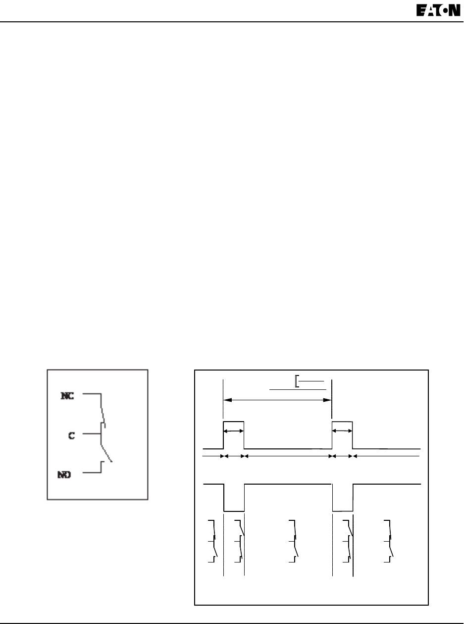
InternalSchematic: Outputtiming:
(De-energizedState)
][
3600
][
WattP
pulse
Watthour
Kh
sT
][
=
90ms
90ms
LED
ON
LED
ON
LED
OFF
LED
OFF
LED
OFF
IR LED Light Pulses
Through Faceplate
NO
C
NC
NO
C
NC
NO
C
NC
NO
C
NC
NO
C
NC
KYZ Output
Contact States
Through Backplate
P[Watt] - Not a scaled value

Chapter 2:
IQ 250/260 Meter Overview and Specications
www.eaton.com IB02601006E 2- 7
Isolation
AllInputsandOutputsaregalvanicallyisolatedto2500Vac
Environmental Rating
Storage: (-20to+70)
0
C
Operating: (-20to+70)
0
C
Humidity: to95%RHNon-condensing
FaceplateRating: NEMA12(WaterResistant),MountingGasketIncluded
Measurement Methods
Voltage,Current: TrueRMS
Power: Samplingatover400SamplesperCycleonAllChannels
Update Rate
Watts,VARandVA: Every6cycles(e.g.,100ms@60Hz)
Allotherparameters: Every60cycles(e.g.,1s@60Hz)
1secondforcurrentonlymeasurement,ifreference
voltageisnotavailable
Communication
Standard:
1.RS485PortthroughBackPlate
2.EnergyPulseOutputthroughBackPlate
Protocols: ModbusRTU,ModbusASCII,DNP3.0
ComPortBaudRate: 9,600to57,600bps
ComPortAddress: 001-247
DataFormat: 8Bit,NoParity
IQ250/260T DefaultInitialCommunicationBaud9600(SeeChapter5)
Mechanical Parameters
Dimensions:seeChapter3.
Weight: 2pounds/0.9kg(shipsina6”/152.4mmcubecontainer)
(WithoutOptionCard)

2-8 IB02601006E www.eaton.com
Chapter 2:
Overview and Specications IQ 250/260 Meter
Compliance
• ULListing:USL/CNLE185559
• CECompliant
• IEC62053-22(0.2%Accuracy)
• ANSIC12.20(0.2%Accuracy)•
• ANSIC62.41(Burst)•
IC12.2• IEC1000-4-2-ESD
• ANSIC62.41tobesuppliedbeforedocumentrelease
Accuracy (SeefullRangespecicationsearlierinthischapter.)
For 23o C,3PhasebalancedWyeorDeltaload,at50or60Hz(asperorder),5A(Class10)
nominalunit:
Parameter Accuracy Accuracy Input Range1
VoltageL-N[V] 0.1%ofreading (69to480)V
VoltageL-L[V] 0.2%ofreading2(120to600)V
CurrentPhase[A] 0.1%ofreading3(0.15to5)A
CurrentNeutral(calculated)
[A]
2%ofFullScale (0.15to5)A@(45to65)Hz
ActivePowerTotal[W] 0.2%ofreading1, 2 (0.15to5)A@(69to480)V@+/-(0.5to1)lag/leadPF
ActiveEnergyTotal[Wh] 0.2%ofreading1, 2 (0.15to5)A@(69to480)V@+/-(0.5to1)lag/leadPF
ReactivePowerTotal[VAR] 0.2%ofreading1, 2 (0.15to5)A@(69to480)V@+/-(0to0.8)lag/leadPF
ReactiveEnergyTotal[VARh] 0.2%ofreading1, 2 (0.15to5)A@(69to480)V@+/-(0to0.8)lag/leadPF
ApparentPowerTotal[VA] 0.2%ofreading1, 2 (0.15to5)A@(69to480)V@+/-(0.5to1)lag/leadPF
ApparentEnergyTotal[VAh] 0.2%ofreading1, 2 (0.15to5)A@(69to480)V@+/-(0.5to1)lag/leadPF
PowerFactor 0.2%ofreading1, 2 (0.15to5)A@(69to480)V@+/-(0.5to1)lag/leadPF
Frequency[Hz] +/-0.03Hz (45to65)Hz
TotalHarmonicDistortion[%] +/-2% (0.5to10)A4or(69to480)V,measurementrange(1to99.99)%
LoadBar +/-1segment (0.005to6)A
1•For2.5elementprogrammedunits,degradeaccuracybyanadditional0.5%ofreading.
•For1A(Class2)Nominal,degradeaccuracybyanadditional0.5%ofreading.
•For1A(Class2)Nominal,theinputcurrentrangeforaccuracyspecicationis20%ofthevalueslisted
inthetable.
2Forunbalancedvoltageinputswhereatleastonecrossesthe150Vautoscalethreshold(forexample,
120V/120V/208Vsystem),degradetheaccuracyto0.4%ofreading.
3Withreferencevoltageapplied(VA,VB,orVC).Otherwise,degradeaccuracyto0.2%.Seehookup
diagrams8,9,and10inChapter4.
4Atleastonevoltageinput(minimum20Vac)mustbeconnectedforTHDmeasurementoncurrent
channels.

Chapter 3:
IQ 250/260 Meter Mechanical Installation
www.eaton.com IB02601006E 3-1
3 Mechanical Installation
Introduction
TheIQ250/260metercanbeinstalledusingastandardANSIC39.1(4”Round)oranIEC92mmDIN(Square)
form.Innewinstallations,simplyuseexistingDINorANSIpunches.Forexistingpanels,pulloutoldanalog
metersandreplacethemwiththeIQ250/260.Thevariousmodelsusethesameinstallation.SeeChapter4for
wiringdiagrams.
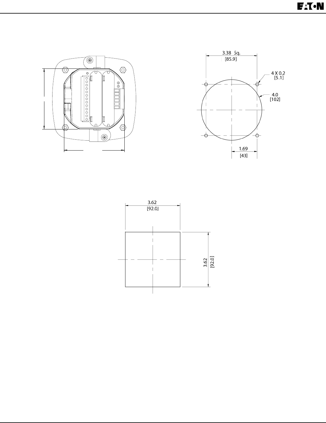
NOTE: Thedrawingsshownbelowandonthenextpagegiveyouthemeterdimensionsininchesand
millimeters(mmshowninbrackets).Toleranceis+/-0.1”[2.54mm].
Figure 3.1: IQ 250/260 Face Figure 3.2: IQ 250/260 Dimensions
Figure 3.3: IQ 250/260T Dimensions
3.56 [9.04]
0.06 [0.15]
0.77 [1.95]
4.85 [12.32]
0.91 [2.31]
5.02 [12.75]
0.77 [1.95]
Gasket
3.25 [8.26]
4.85 [12.32]
4.85 [12.32]
3.56 [9.04] 3.25 [8.26]
0.95 [2.41]
3.56 [9.04]
0.06 [0.15]
0.77 [1.95]
4.85 [12.32]
0.91 [2.31]
5.02 [12.75]
0.77 [1.95]
Gasket
3.25 [8.26]
4.85 [12.32]
4.85 [12.32]
3.56 [9.04] 3.25 [8.26]
0.95 [2.41]
3.56 [9.04]
0.06 [0.15]
0.77 [1.95]
4.85 [12.32]
0.91 [2.31]
5.02 [12.75]
0.77 [1.95]
Gasket
3.25 [8.26]
4.85 [12.32]
4.85 [12.32]
3.56 [9.04] 3.25 [8.26]
0.95 [2.41]
3-2 IB02601006E www.eaton.com
Chapter 3:
Mechanical Installation IQ 250/260 Meter
Fig. 3.4: IQ 250/260 Back Face Figure 3.5: ANSI Mounting Panel Cutout
Figure 3.6: DIN Mounting Cutout
3.56 [9.04]
0.06 [0.15]
0.77 [1.95]
4.85 [12.32]
0.91 [2.31]
5.02 [12.75]
0.77 [1.95]
Gasket
3.25 [8.26]
4.85 [12.32]
4.85 [12.32]
3.56 [9.04] 3.25 [8.26]
0.95 [2.41]
Chapter 3:
IQ 250/260 Meter Mechanical Installation
www.eaton.com IB02601006E 3-3
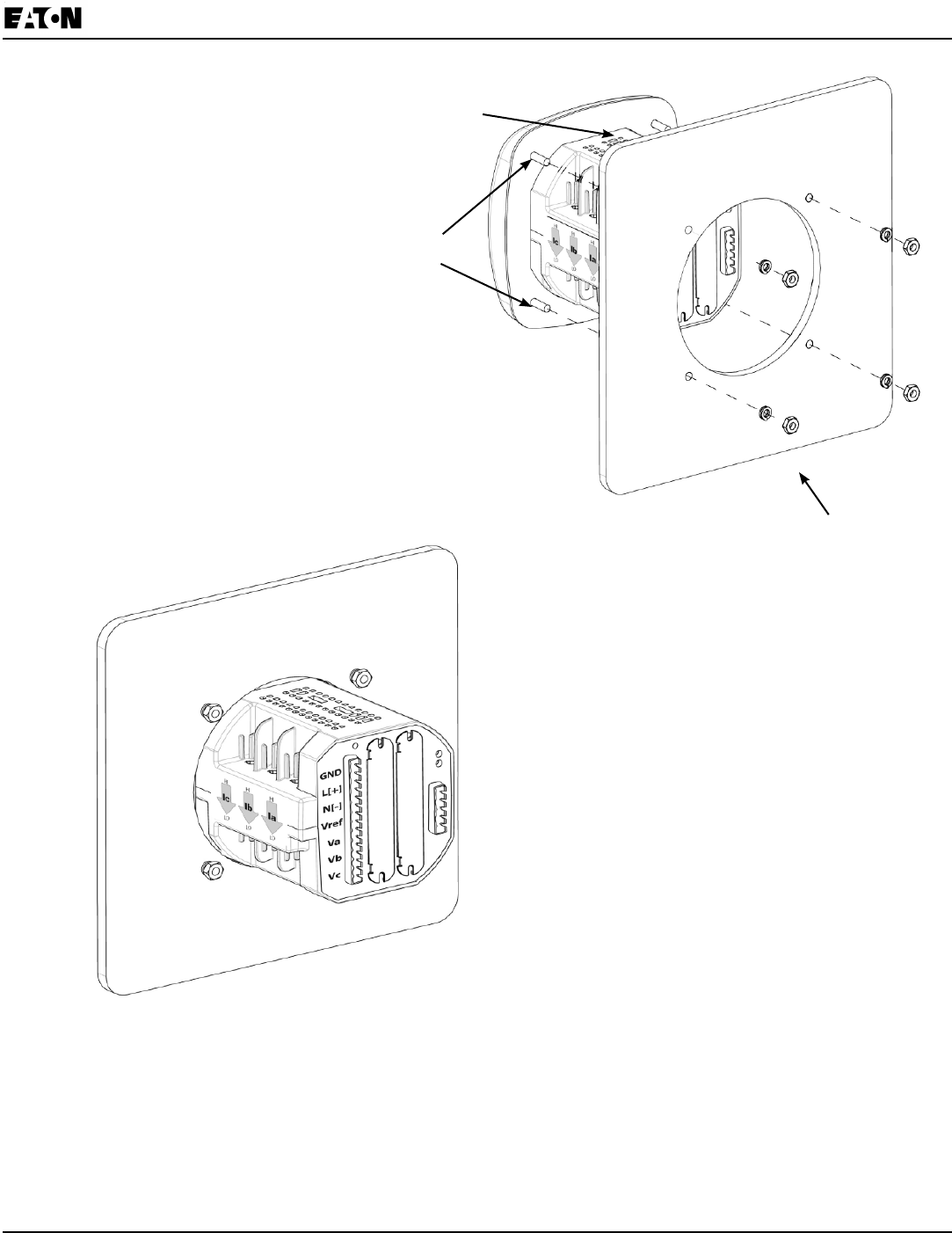
ANSI Installation Steps
1.Insert4threadedrodsbyhandintothebackofmeter.Twistuntilsecure.
2.SlideNEMA12MountingGasketontobackofmeterwithrodsinplace.
3.SlidemeterwithMountingGasketintopanel.
4.Securefrombackofpanelwithlockwasherandnutoneachthreadedrod.
Useasmallwrenchtotighten.Donotovertighten.The maximum installation torque is 0.4 Newton-
Meter.
NEMA 12 Mounting Gasket
Threaded Rods
Lock Washer
and Nut
Figure 3.7: ANSI Mounting Procedure
3-4 IB02601006E www.eaton.com
Chapter 3:
Mechanical Installation IQ 250/260 Meter
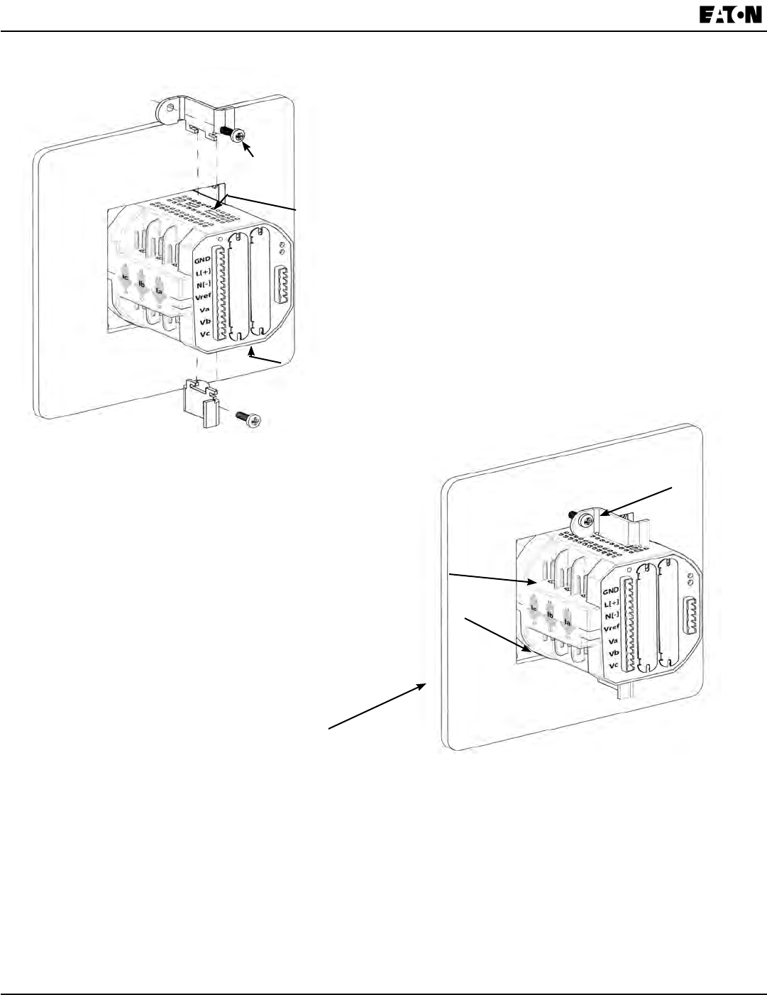
DIN Installation Steps
1.SlidemeterwithNEMA12MountingGasketintopanel.(RemoveANSIStuds,ifinplace.)
2.Frombackofpanel,slide2DINMountingBracketsintogroovesintopandbottomof
meterhousing.Snapintoplace.
3.Securemetertopanelwithlockwasheranda#8screwthrougheachofthe2mounting
brackets.Tightenwitha#2Phillipsscrewdriver.Donotovertighten.The maximum installation torque
is 0.4 Newton-Meter.
DIN Mounting Bracket (supplied by others: if needed, contact
technical support referenced on page 1-1)
Top Mounting Bracket Groove
Bottom Mounting Bracket Groove
#8 Screw
IQ 250/260 Meter
with NEMA 12 Mounting
Gasket
Remove (unscrew) ANSI
Studs for DIN Installation
Figure 3.8: DIN Mounting Procedure
Chapter 3:
IQ 250/260 Meter Mechanical Installation
www.eaton.com IB02601006E 3-5
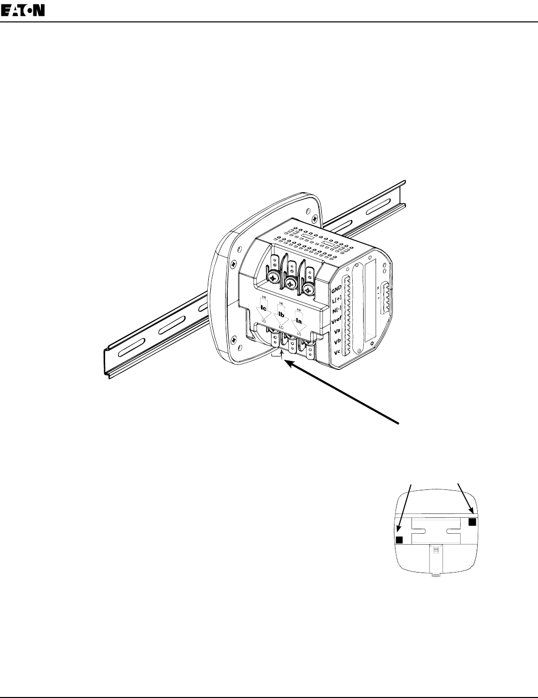
IQ 250/260T Transducer Installation
TheIQ250/260TTransducermodelisinstalledusingDINRailMounting.
SpecsforDINRailMounting: InternationalStandardsDIN46277/3
DINRail(Slotted)Dimensions: 0.297244”x1.377953”x3”(inches)
7.55mmx35mmx76.2mm(millimeters)
Figure 3.9: DIN Rail Mounting Procedure Release Clip
1.SlidetopgrooveofmeterontotheDINRail.
2.Pressgentlyuntilthemeterclicksintoplace.
NOTES:
• ToremovethemeterfromtheDINRail,pulldownon
theReleaseCliptodetachtheunitfromtherail.
•IfmountingwiththeDINRailprovided,usetheBlackRubber
Stoppers(alsoprovided).Seegureontheright.
NOTE ON DIN RAILS:
DINRailsarecommonlyusedasamountingchannelformost
terminalblocks,controldevices,circuitprotectiondevicesand
PLCs.DINRailsaremadeofcoldrolledsteelelectrolitically
platedandarealsoavailableinaluminum,PVC,stainlesssteel
and copper.
Release
Clip

3-6 IB02601006E www.eaton.com
Chapter 3:
Mechanical Installation IQ 250/260 Meter

Chapter 4:
IQ 250/260 Meter Electrical Installation
www.eaton.com IB02601006E 4-1
4 Electrical Installation
Considerations When Installing Meters
InstallationoftheIQ250/260Metermustbeperformedonly byqualiedpersonnelwhofollow
standardsafetyprecautionsduringallprocedures.Thosepersonnelshouldhaveappropriate
trainingandexperiencewithhighvoltagedevices.Appropriatesafetygloves,safetyglassesand
protectiveclothingisrecommended.
DuringnormaloperationoftheIQ250/260Meter,dangerousvoltagesowthroughmanypartsofthemeter,includ-
ing:TerminalsandanyconnectedCTs(CurrentTransformers)andPTs(PotentialTransformers),allI/OModules
(InputsandOutputs)andtheircircuits.AllPrimaryandSecondarycircuitscan,attimes,producelethalvoltages
andcurrents.Avoidcontactwithanycurrent-carryingsurfaces.
DonotusethemeteroranyI/OOutputDeviceforprimaryprotectionorinanenergy-limitingcapacity.Themeter
canonlybeusedassecondaryprotection.Donotusethemeterforapplicationswherefailureofthemetermay
causeharmordeath.Donotusethemeterforanyapplicationwheretheremaybeariskofre.
Allmeterterminalsshouldbeinaccessibleafterinstallation.
Donotapplymorethanthemaximumvoltagethemeteroranyattacheddevicecanwithstand.Refertometerand/
ordevicelabelsandtotheSpecicationsforalldevicesbeforeapplyingvoltages.DonotHIPOT/Dielectrictestany
Outputs,InputsorCommunicationsterminals.
EatonrecommendstheuseofShortingBlocksandFusesforvoltageleadsandpowersupplytopreventhazard-
ousvoltageconditionsordamagetoCTs,ifthemeterneedstoberemovedfromservice.CTgroundingisoptional.
NOTES:
• IFTHEEQUIPMENTISUSEDINAMANNERNOTSPECIFIEDBYTHEMANUFACTURER,THE
PROTECTIONPROVIDEDBYTHEEQUIPMENTMAYBEIMPAIRED.
• THEREISNOREQUIREDPREVENTIVEMAINTENANCEORINSPECTIONNECESSARYFOR
SAFETY.HOWEVER,ANYREPAIRORMAINTENANCESHOULDBEPERFORMEDBYTHE
FACTORY.
DISCONNECT DEVICE:Thefollowingpartisconsideredtheequipmentdisconnectdevice.
ASWITCHORCIRCUIT-BREAKERSHALLBEINCLUDEDINTHEEND-USE
EQUIPMENTORBUILDINGINSTALLATION.THESWITCHSHALLBEINCLOSE
PROXIMITYTOTHEEQUIPMENTANDWITHINEASYREACHOFTHEOPERATOR.THE
SWITCHSHALLBEMARKEDASTHEDISCONNECTINGDEVICEFORTHEEQUIPMENT.
4-2 IB2601006E www.eaton.com
Chapter 4:
Electrical Installation IQ 250/260 Meter
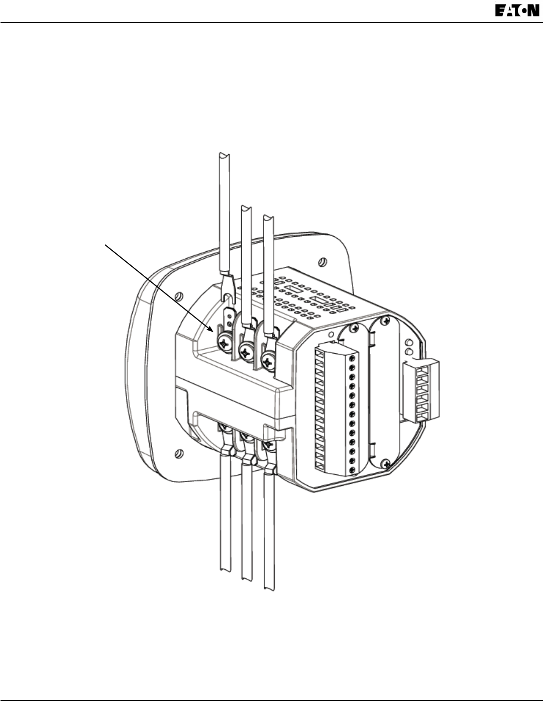
CT Leads Terminated to Meter
TheIQ250/260isdesignedtohaveCurrentInputswiredinoneofthreeways.Diagram4.1showsthemosttypical
connectionwhereCTLeadsareterminatedtothemeterattheCurrentGills.ThisconnectionusesNickel-Plated
BrassStuds(CurrentGills)withscrewsateachend.ThisconnectionallowstheCTwirestobeterminatedusing
eitheran“O”ora“U”lug.Tightenthescrewswitha#2Phillipsscrewdriver.
OthercurrentconnectionsareshowninFigures4.2and4.3.VoltageandRS485/KYZConnectionisshownin
Figure4.4.
WiringDiagramsareshownlaterinthischapter.
CommunicationsConnectionsaredetailedinChapter5.
Current Gills
(Nickel-Plated Brass Stud)
Figure 4.1: CT Leads terminated to Meter, #8 Screw for Lug Connection
Chapter 4:
IQ 250/260 Meter Electrical Installation
www.eaton.com IB02601006E 4-3
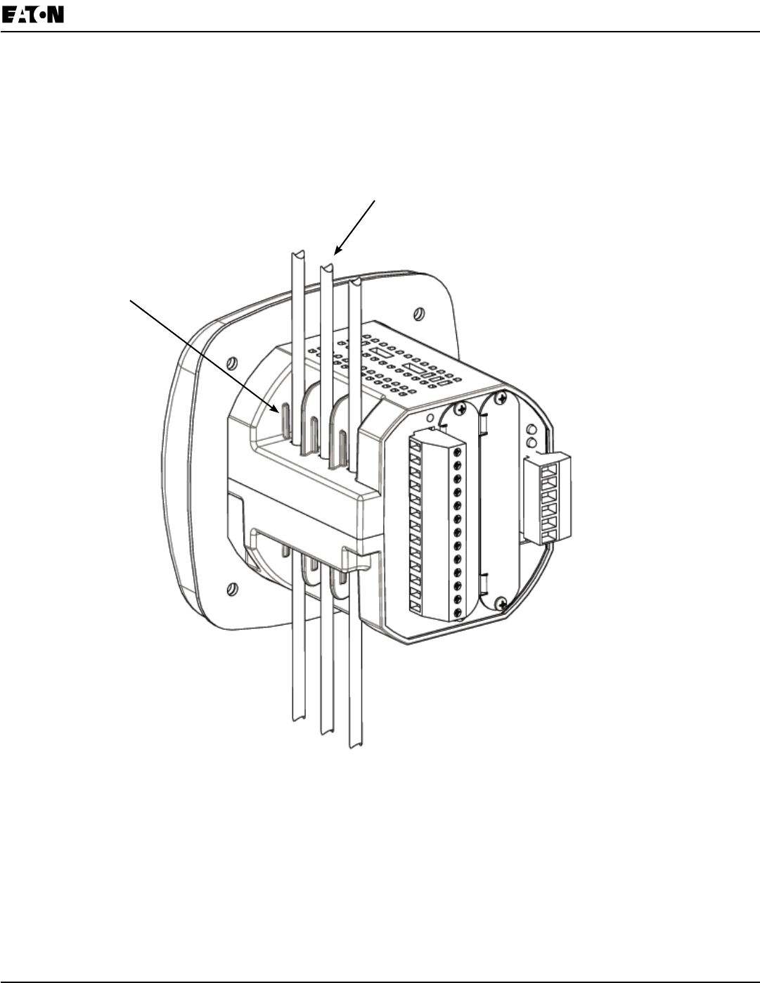
CT Leads Pass Through (No Meter Termination)
ThesecondmethodallowstheCTwirestopassthroughtheCTInputswithoutterminatingatthemeter.Inthis
case,removetheCurrentGillsandplacetheCTwiredirectlythroughtheCTopening.Theopeningwillaccomo-
dateupto0.177”/4.5mmmaximumdiameterCTwire.
CT Wire passing through meter
Current Gills removed
Figure 4.2: Pass-Through Wire Electrical Connection
4-4 IB2601006E www.eaton.com
Chapter 4:
Electrical Installation IQ 250/260 Meter
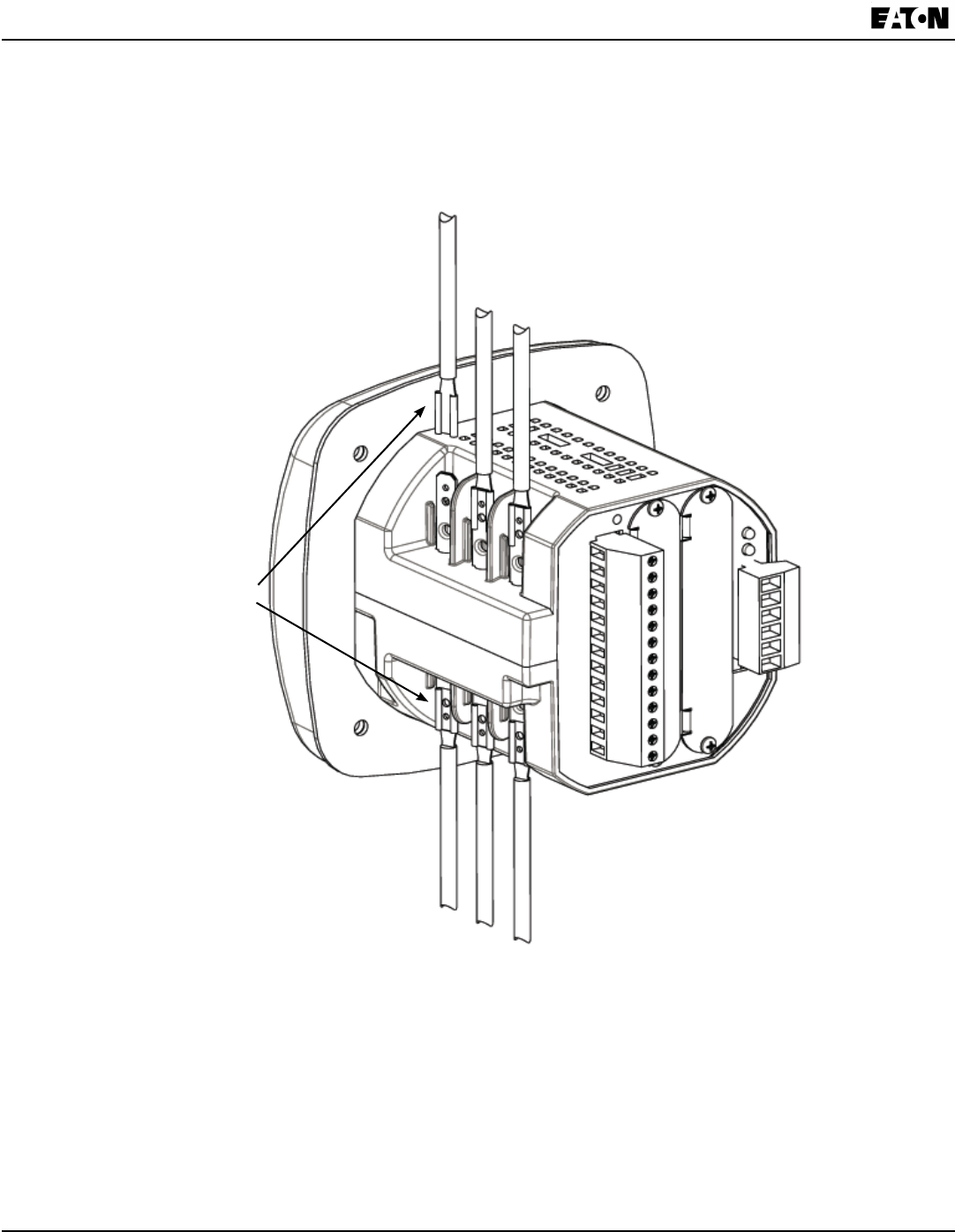
Quick Connect Crimp-on Terminations
ForQuickTerminationorforPortableApplications,a0.25”QuickConnectCrimp-onConnectorscanalsobeused.
Quick Connect
Crimp-on Terminations
Figure 4.3: Quick Connect Electrical Connection
Chapter 4:
IQ 250/260 Meter Electrical Installation
www.eaton.com IB02601006E 4-5
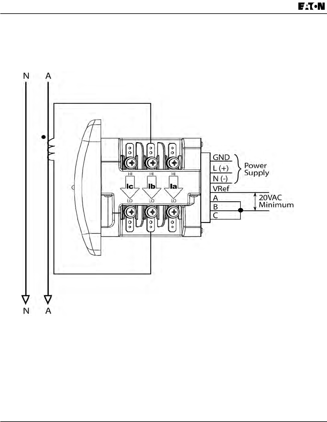
Voltage and Power Supply Connections
VoltageInputsareconnectedtothebackoftheunitviaaoptionalwireconnectors.Theconnectorsaccomodate
AWG#12-26/(0.129-3.31)mm2.
Figure 4.4: Voltage Connection
Ground Connections
Themeter’sGroundTerminalsshouldbeconnecteddirectlytotheinstallation’sprotectiveearthground.UseAWG#
12/2.5 mm2wireforthisconnection.
Voltage Fuses
Eatonrecommendstheuseoffusesoneachofthesensevoltagesandonthecontrolpower,eventhoughthewiring
diagramsinthischapterdonotshowthem.
Usea0.1Ampfuseoneachvoltageinput.
Usea3AmpSlowBlowfuseonthepowersupply.
Power
Supply
Inputs
Voltage
Inputs
RS485 and KYZ
Pulse Output
CAUTION! Do not apply
input or supply voltage
to these terminals.

4-6 IB2601006E www.eaton.com
Chapter 4:
Electrical Installation IQ 250/260 Meter
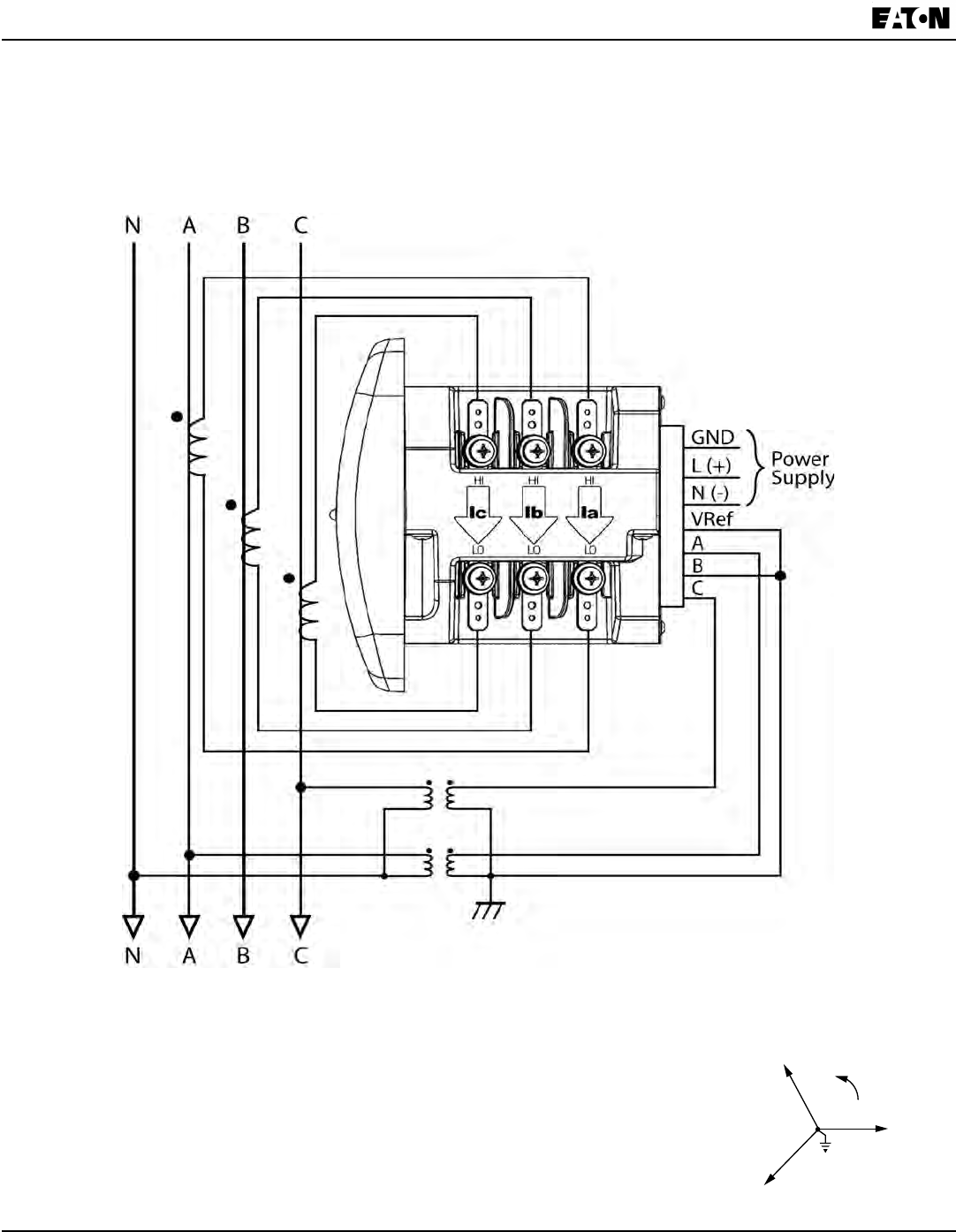
Electrical Connection Diagrams
ThefollowingpagescontainelectricalconnectiondiagramsfortheIQ250/260meter.Choosethediagramthatbest
suitsyourapplication.BesuretomaintaintheCTpolaritywhenwiring.
Thediagramsarepresentedinthefollowingorder:
1.ThreePhase,Four-WireSystemWye/DeltawithDirectVoltage,3Element
a.ExampleofDualPhaseHookup
b.ExampleofSinglePhaseHookup
2.ThreePhase,Four-WireSystemWyewithDirectVoltage,2.5Element
3 Three-Phase,Four-WireWye/DeltawithPTs,3Element
4.Three-Phase,Four-WireWyewithPTs,2.5Element
5.Three-Phase,Three-WireDeltawithDirectVoltage
6.Three-Phase,Three-WireDeltawith2PTs
7.Three-Phase,Three-WireDeltawith3PTs
8.CurrentOnlyMeasurement(ThreePhase)
9.CurrentOnlyMeasurement(DualPhase)
10.CurrentOnlyMeasurement(SinglePhase)
Chapter 4:
IQ 250/260 Meter Electrical Installation
www.eaton.com IB02601006E 4-7
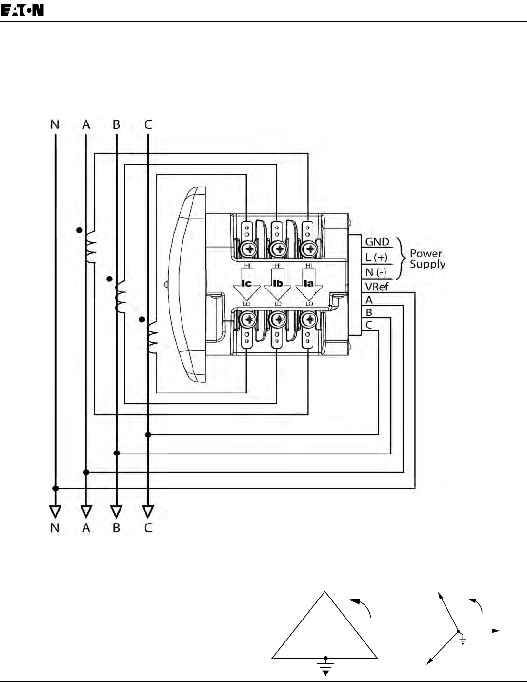
Select: “ 3 EL WYE ” (3 Element Wye) from the
IQ 250/260’s Front Panel Display. (See Chapter 6.)
C
B
A
C
B A
1. Service: WYE/Delta, 4-Wire with No PTs, 3 CTs
4-8 IB2601006E www.eaton.com
Chapter 4:
Electrical Installation IQ 250/260 Meter
1a. Example of Dual Phase Hookup
Chapter 4:
IQ 250/260 Meter Electrical Installation
www.eaton.com IB02601006E 4-9
1b. Example of Single Phase Hookup

4-10 IB2601006E www.eaton.com
Chapter 4:
Electrical Installation IQ 250/260 Meter
2. Service: 2.5 Element WYE, 4-Wire with No PTs, 3 CTs
Select: “ 2.5 EL WYE ” (2.5 Element Wye) from the
IQ 250/260’s Front Panel Display. (See Chapter 6.)
C
B
A

Chapter 4:
IQ 250/260 Meter Electrical Installation
www.eaton.com IB02601006E 4-11
3. Service: WYE/Delta, 4-Wire with 3 PTs, 3 CTs
Select: “ 3 EL WYE ” (3 Element Wye) from the
IQ 250/260’s Front Panel Display. (See Chapter 6.)
C
B
A
C
B A
C
B A
4-12 IB2601006E www.eaton.com
Chapter 4:
Electrical Installation IQ 250/260 Meter
4. Service: 2.5 Element WYE, 4-Wire with 2 PTs, 3 CTs
Select: “ 2.5 EL WYE ” (2.5 Element Wye) from the
IQ 250/260’s Front Panel Display. (See Chapter 6.)
C
B
A
Chapter 4:
IQ 250/260 Meter Electrical Installation
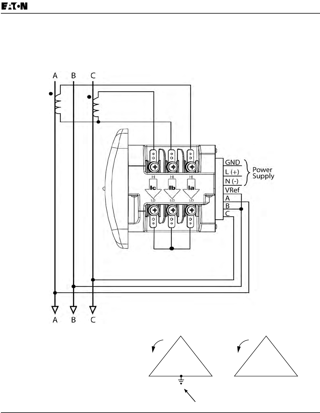
www.eaton.com IB02601006E 4-13
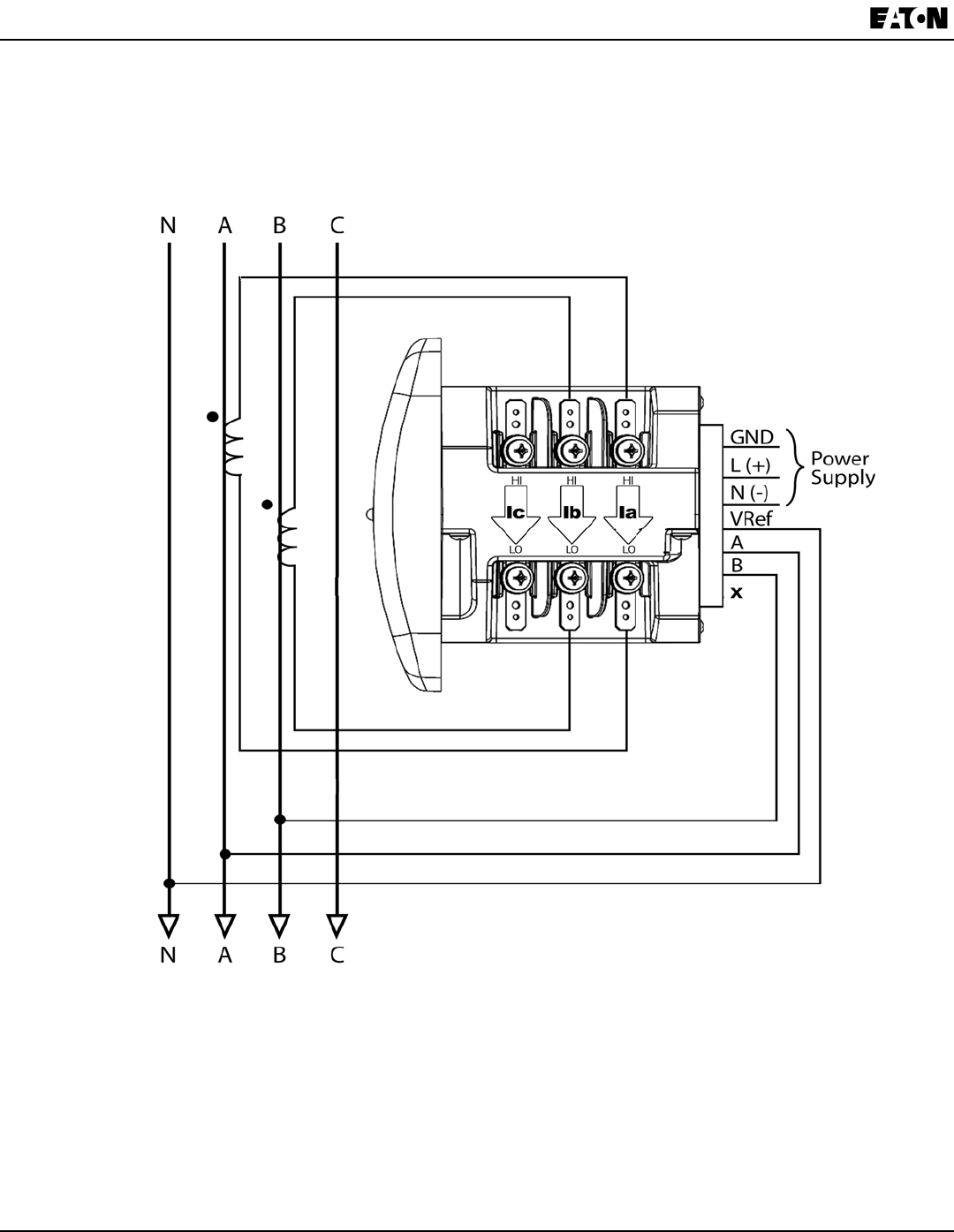
5. Service: Delta, 3-Wire with No PTs, 2 CTs
Select: “ 2 Ct dEL ” (2 CT Delta) from the
IQ 250/260’s Front Panel Display. (See Chapter 6.) Not connected to meter
C
B A
C
B A

4-14 IB2601006E www.eaton.com
Chapter 4:
Electrical Installation IQ 250/260 Meter
6. Service: Delta, 3-Wire with 2 PTs, 2 CTs
C
B A
C
B A
Select: “ 2 Ct dEL ” (2 CT Delta) from the
IQ 250/260’s Front Panel Display. (See Chapter 6.) Not connected to meter
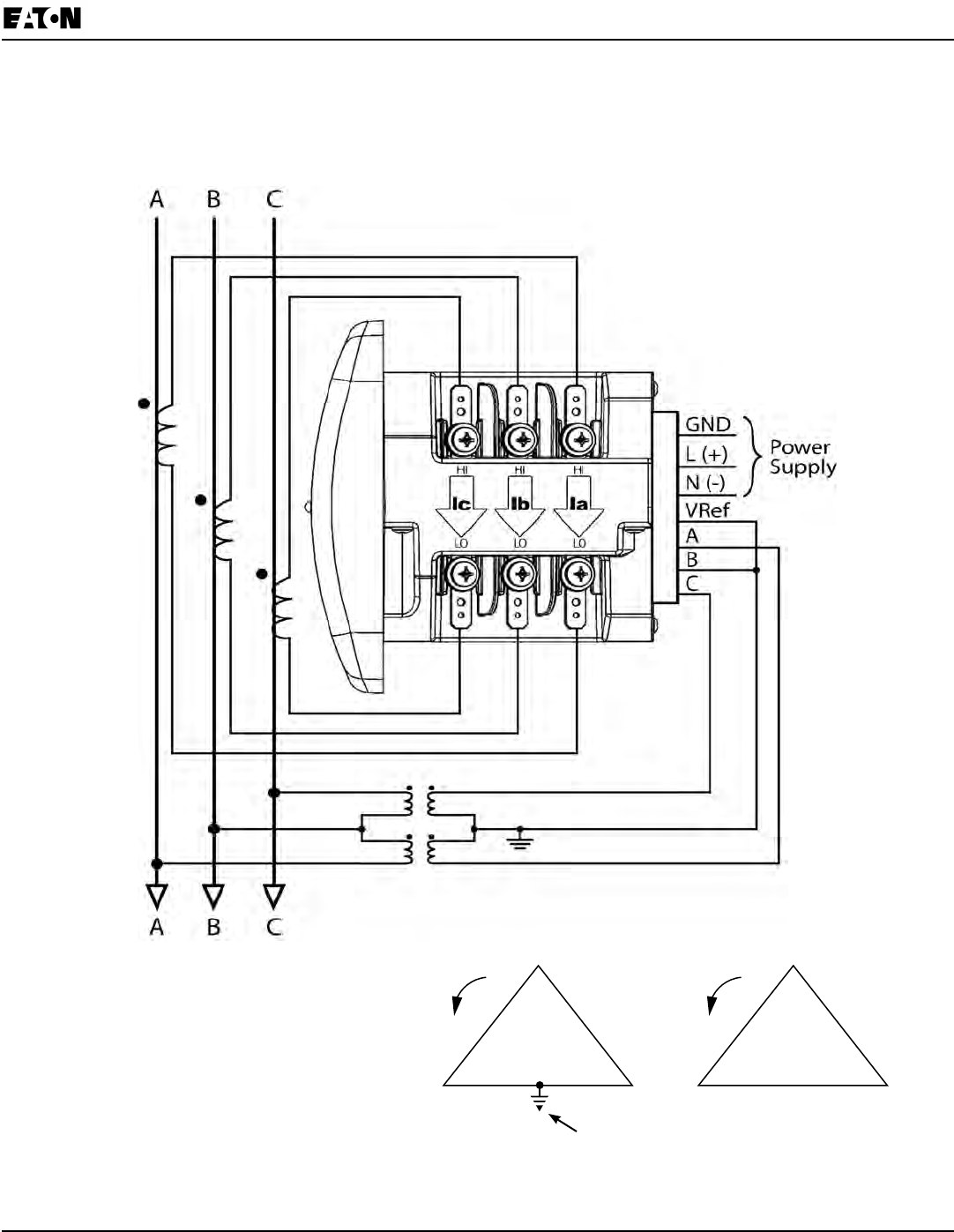
Chapter 4:
IQ 250/260 Meter Electrical Installation
www.eaton.com IB02601006E 4-15
7. Service: Delta, 3-Wire with 2 PTs, 3 CTs
NOTE: The third CT for hookup is optional and is for Current Measurement only.
C
B A
C
B A
Select: “ 2 Ct dEL ” (2 CT Delta) from the
IQ 250/260’s Front Panel Display. (See Chapter 6.) Not connected to meter

4-16 IB2601006E www.eaton.com
Chapter 4:
Electrical Installation IQ 250/260 Meter
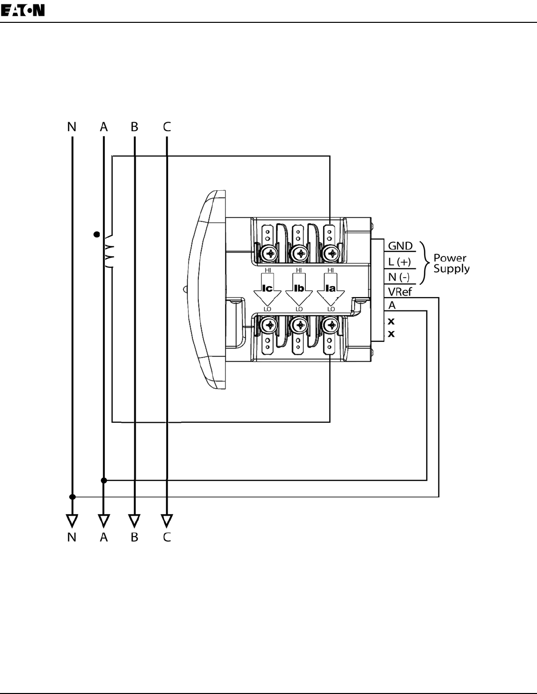
8. Service: Current Only Measurement (Three Phase)
Select: “ 3 EL WYE ” (3 Element Wye) from the
IQ 250/260’s Front Panel Display. (See Chapter 6.)
* For improved accuracy, this connection is recommended, but not required.
*
Chapter 4:
IQ 250/260 Meter Electrical Installation
www.eaton.com IB02601006E 4-17
9. Service: Current Only Measurement (Dual Phase)
Select: “ 3 EL WYE ” (3 Element Wye) from the
IQ 250/260’s Front Panel Display. (See Chapter 6.)
* For improved accuracy, this connection is recommended, but not required.
*
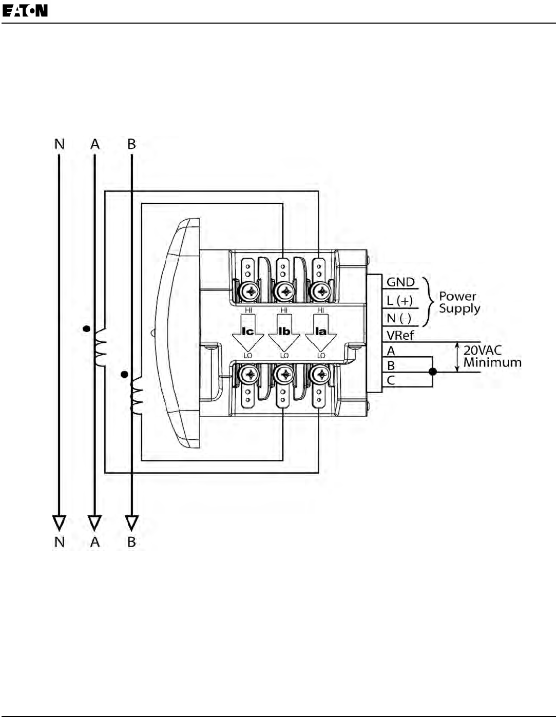
4-18 IB2601006E www.eaton.com
Chapter 4:
Electrical Installation IQ 250/260 Meter
10. Service: Current Only Measurement (Single Phase)
* For improved accuracy, this connection is recommended, but not required.
*
Select: “ 3 EL WYE ” (3 Element Wye) from the
IQ 250/260’s Front Panel Display. (See Chapter 6.)
Chapter 5:
IQ 250/260 Meter Communication Installation
www.eaton.com IB02601006E 5-1
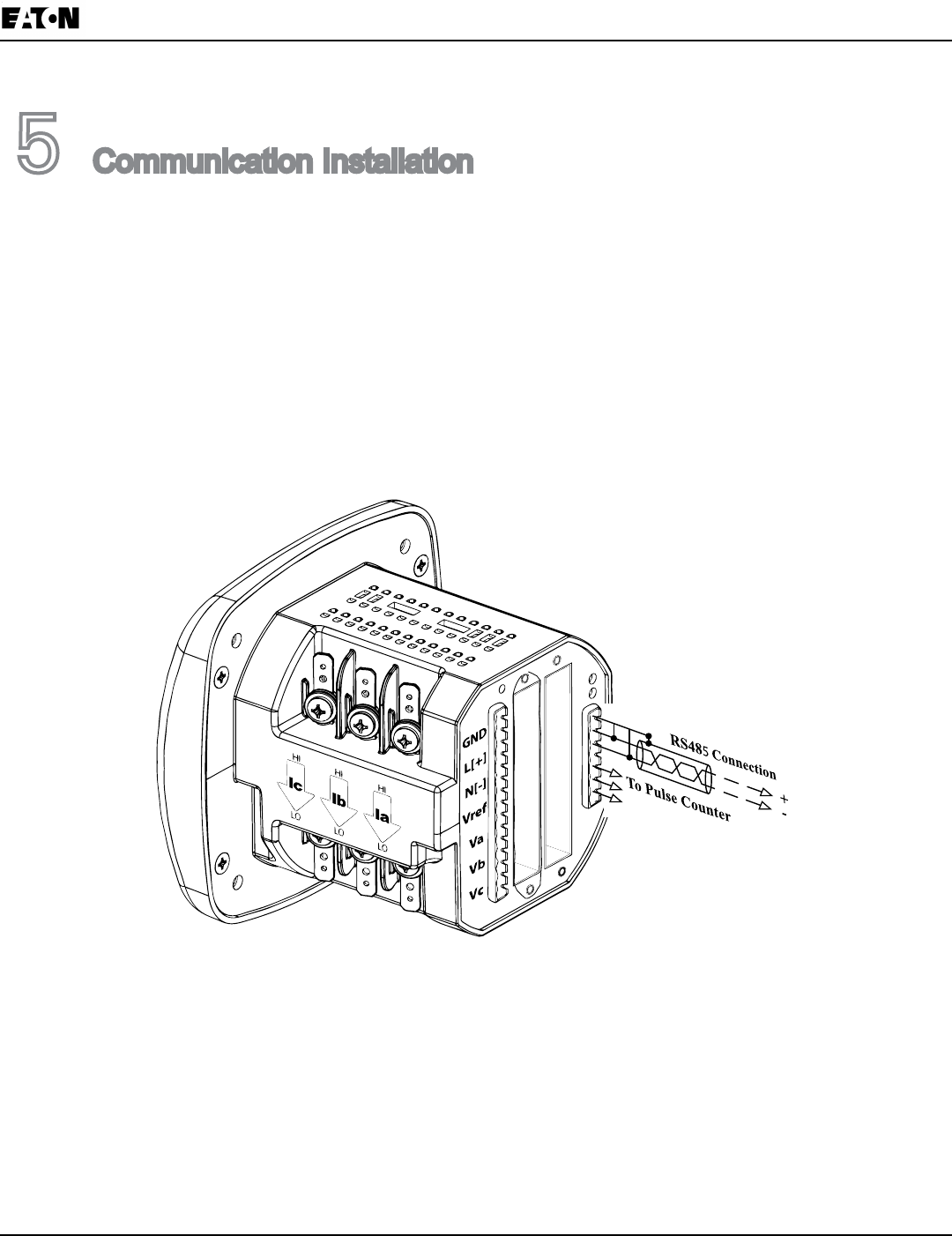
5 CommunicationInstallation
IQ 250/260 Communication
TheIQ250/260MeterprovidesRS485communicationspeakingModbusASCII,ModbusRTU,andDNP3.0
protocols.
RS485 / KYZ Output (Com 2)
Com2providesacombinationRS485andanEnergyPulseOutput(KYZpulse).SeeChapter2fortheKYZOut-
putSpecications;seeChapter6forPulseConstants.
RS485allowsyoutoconnectoneormultipleIQ250/260meterstoaPCorotherdevice,ateitheralocalorremote
site.AllRS485connectionsareviableforupto4000feet(1219.20meters).
Figure 5.1: IQ 250/260 Back with RS485 Communication Installation
5-2 IB02601006E www.eaton.com
Chapter 5:
Communication Installation IQ 250/260 Meter
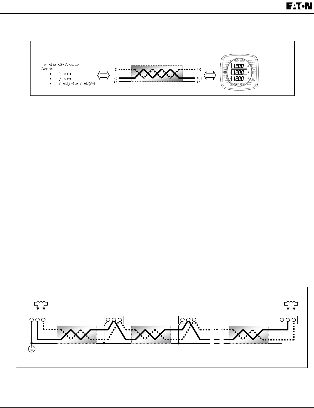
Figure5.2showsthedetailofa2-wireRS485connection.
Figure 5.2: 2-wire RS485 Connection
NOTES:
For All RS485 Connections:
•Useashieldedtwistedpaircable22AWG(0.33mm2)orthicker,andgroundtheshield,preferablyatonelocation
only.
•Establishpoint-to-pointcongurationsforeachdeviceonaRS485bus:connect(+)terminalsto(+)terminals;
connect(-)terminalsto(-)terminals.
•Youmayconnectupto31metersonasinglebususingRS485.Beforeassemblingthebus,eachmetermusthave
auniqueaddress:refertoChapter8forinstructions.
•Protectcablesfromsourcesofelectricalnoise.
•Avoidboth“Star”and“Tee”connections(seeFigure5.4).
•No more than two cables shouldbeconnectedat any one pointonanRS485network,whethertheconnections
are for devices, converters, or terminal strips.
•Includeallsegmentswhencalculatingthetotalcablelengthofanetwork.IfyouarenotusinganRS485repeater,
themaximumlengthforcableconnectingalldevicesis4000feet(1219.20meters).
•ConnectshieldtoRS485MasterandindividualdevicesasshowninFigure5.3.Youmayalsoconnecttheshield
toearth-groundatonepoint.
• Termination Resistors(RT)maybeneededonbothendsforlongerlengthtransmissionlines.However,since
themeterhassomelevelofterminationinternally,TerminationResistorsmaynotbeneeded.Whentheyareused,
thevalueoftheTerminationResistorsisdeterminedbytheelectricalparametersofthecable.
Figure5.3showsarepresentationofanRS485DaisyChainconnection.
Figure 5.3: RS485 Daisy Chain Connection
IQ 250/260 485 Connection
Twisted pair, shielded (SH) cable
RT
+ - SH
RT
+ - SH
+ - SH + - SH
Slave device 1 Slave device 2
Last Slave device N Master device
Earth Connection, preferably at
single location
Twisted pair, shielded (SH) cable Twisted pair, shielded (SH) cable

Chapter 5:
IQ 250/260 Meter Communication Installation
www.eaton.com IB02601006E 5-3
Figure 5.4: Incorrect “T” and “Star” Topologies
Twisted pair, shielded (SH) cable
+ - SH
+ - SH
+ - SH
Slave device 1
Slave device 2
Last Slave device N Master device
Earth Connection, preferably at
sin
g
le location
Twisted pair, shielded (SH) cable Twisted pair, shielded (SH) cable
Twisted pair, shielded (SH) cable
+ -SH
Twisted pair, shielded (SH) cable
Twisted pair, shielded (SH) cable Twisted pair, shielded (SH) cable
+ - SH +- SH
+ - SH + -SH
Master device
Slave device 1Slave device 2
Slave device 3Slave device 4
R
T
R
T
+ - SH
Long stub results “T” connection that can cause
interference
p
roblem!
“STAR” connection can cause interference
p
roblem!

5-4 IB02601006E www.eaton.com
Chapter 5:
Communication Installation IQ 250/260 Meter
Using the Power Xpert® Gateway
ThePowerXpert®GatewayallowsanIQ250/260tocommunicatewithaPCthroughastandardwebbrowser.See
the
PowerXpert
®
GatewayUserGuide
,documentnumber164201670,foradditionalinformation.
IQ 250/260T Communication Information
TheIQ250/260TTransducermodeldoesnotincludeadisplayorbuttonsonthefrontfaceofthemeter.Program-
mingandcommunicationutilizetheRS485connectiononthebackfaceofthemetershowninsection5.1.2.Once
aconnectionisestablished,EatonMeterCongurationSoftwarecanbeusedtoprogramthemeterandcommuni-
catetoIQ250/260Tslavedevices.Refertochapter8forinstructionsonusingthesoftwaretoprogramthemeter.
Meter Connection
Toprovidepowertothemeter,attachanAux cabletoGND,L(+)andN(-)RefertoChapter4,Figure1.
The RS485 cableattachestoSH,B(-)andA(+)asshowninFigure5.3ofthischapter.
Chapter 6:
IQ 250/260 Meter Using the IQ 250/260
www.eaton.com IB02601006E 6-1
6 UsingtheIQ250/260
Introduction
Youcanusethe Elements and ButtonsontheIQ250/260meter’sfacetoviewmeterreadings,resetand/or
conguretheIQ250/260,andperformrelatedfunctions.ThefollowingsectionsexplaintheElementsandButtons
and detail their use.
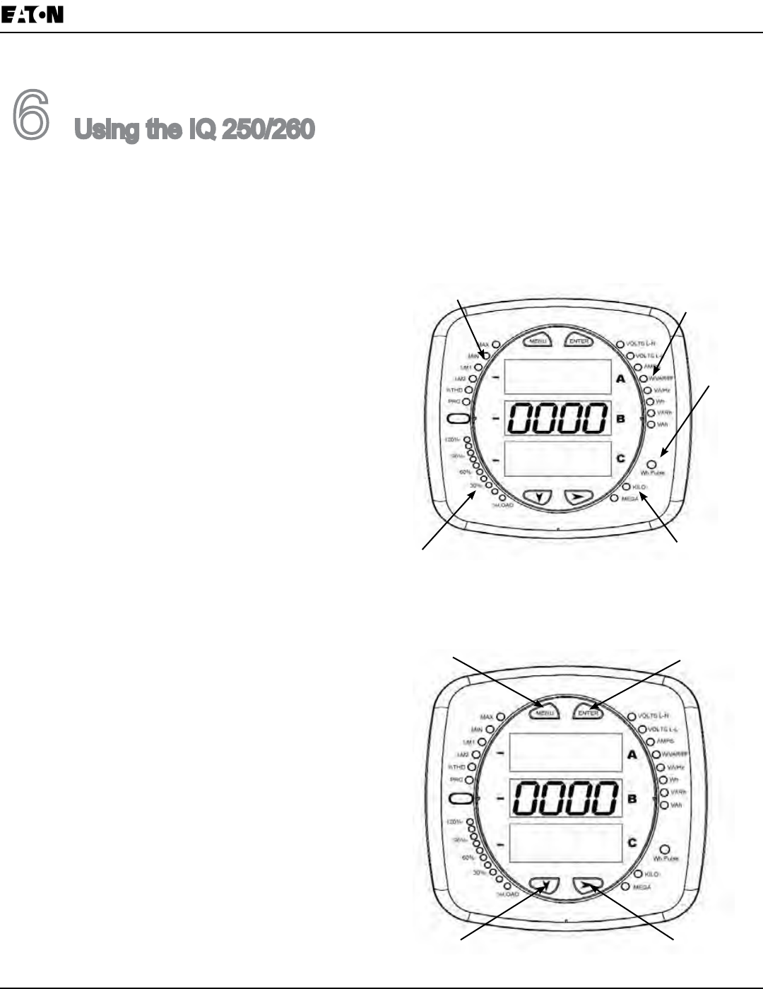
Understanding Meter Face Elements
Themeterfacefeaturesthefollowingelements:
•Reading Type Indicator:
IndicatesTypeofReading
•Parameter Designator:
IndicatesReadingDisplayed
•Watt-Hour Test Pulse:
EnergyPulseOutputtoTestAccuracy
•Scaling Factor:
KiloorMegamultiplierofDisplayedReadings
•% of Load Bar:
GraphicDisplayofAmpsas%oftheLoad
Understanding Meter Face Buttons
The meter face has Menu, Enter, Down and
Right buttons,whichallowyoutoperformthe
followingfunctions:
•ViewMeterInformation
•EnterDisplayModes
•CongureParameters(maybePasswordProtected)
•PerformResets(maybePasswordProtected)
•PerformLEDChecks
•ChangeSettings
•ViewParameterValues
•ScrollParameterValues
•ViewLimitStates
Parameter
Designator
Watt-Hour
Test Pulse
Scaling
Factor
% of Load Bar
Reading Type
Indicator
Figure 6.1: Face Plate of IQ 250/260 with Elements
Figure 6.2: Face Plate of IQ 250/260 with Buttons
Enter
Menu
Down Right

6-2 IB02601006E www.eaton.com
Chapter 6:
Using the IQ 250/260 IQ 250/260 Meter
Using the Front Panel
YoucanaccessfourmodesusingtheIQ250/260frontpanelbuttons:
•Operating Mode(Default)
•Reset Mode
•Conguration Mode
•Information Mode. Information Mode displaysasequenceofscreensthatshowmodelinformation,suchas
Frequency and Amps.
UsetheMenu, Enter, Down and Rightbuttonstonavigatethrougheachmodeanditsrelatedscreens.
NOTES:
•
AppendixA
contains the complete Navigation Mapforthefrontpaneldisplaymodesandtheirscreens.
•Themetercanalsobeconguredusingsoftware;seeChapter8
for instructions.
Understanding Startup and Default Displays
UponPowerUp,themeterdisplaysasequenceofscreens:
•Lamp Test ScreenwhereallLEDsarelit
• Lamp Test Screenwherealldigitsarelit
•Firmware Screenshowingbuildnumber
•Error Screen(ifanerrorexists).
Afterstartup,ifauto-scrollingisenabled,theIQ250/260scrollstheparameterreadingsontherightsideofthe
frontpanel.TheKiloorMegaLEDlights,showingthescalefortheWh,VARhandVAhreadings.Figure6.3
showsanexampleofaWhreading.
TheIQ250/260continuestoprovidescrollingreadingsuntiloneofthebuttonsonthefrontpanelispressed,
causingthemetertoenteroneoftheotherModes.
Figure 6.3: Wh Reading
Chapter 6:
IQ 250/260 Meter Using the IQ 250/260
www.eaton.com IB02601006E 6-3
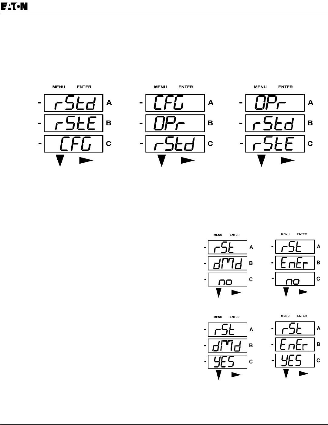
Using the Main Menu
1. Press the Menubutton.TheMainMenuscreenappears.
•TheReset: Demandmode(rStd)appearsintheAwindow.UsetheDown buttontoscroll,causingthe
Reset: Energy(rStE),Conguration(CFG), Operating(OPr), and Information (InFo) modes to move to the
A window.
•ThemodethatiscurrentlyashingintheAwindowisthe“Active”mode,whichmeansitisthemodethatcan
becongured.
For example: Press Down Twice- CFG moves to A window. Press Down Twice - OPr moves to A window.
2. Press the EnterbuttonfromtheMainMenutoviewtheParametersscreenforthemodethatiscurrently
active.
Using Reset Mode
ResetModehastwo options:
• Reset: Demand(rStd):resetstheMaxandMinvalues.
• Reset: Energy (rStE):resetstheenergyaccumulatorelds.
Press the EnterbuttonwhileeitherrStd or rStE isintheAwindow.
The Reset Demand No or Reset Energy No screen appears.
•IfyoupresstheEnter button again,theMainMenuappears,
withthe next modeintheAwindow.(TheDownbutton
doesnotaffectthisscreen.)
•IfyoupresstheRightbutton,theReset Demand YES or
Reset Energy YES screen appears.
Press Enter to perform a reset.
NOTE: IfPasswordProtectionisenabledforReset,youmust
enterthefourdigitPasswordbeforeyoucanresetthemeter.
(SeeChapter8forinformationonPasswordProtection.)
To enter a password, follow the instructions on the next
page.
CAUTION! Reset Demand YES resets all Max and Min values.
Onceyouhaveperformedareset,thescreendisplayseither“rSt dMd donE”
or “rSt EnEr donE”andthenresumesauto-scrollingparameters.
6-4 IB02601006E www.eaton.com
Chapter 6:
Using the IQ 250/260 IQ 250/260 Meter
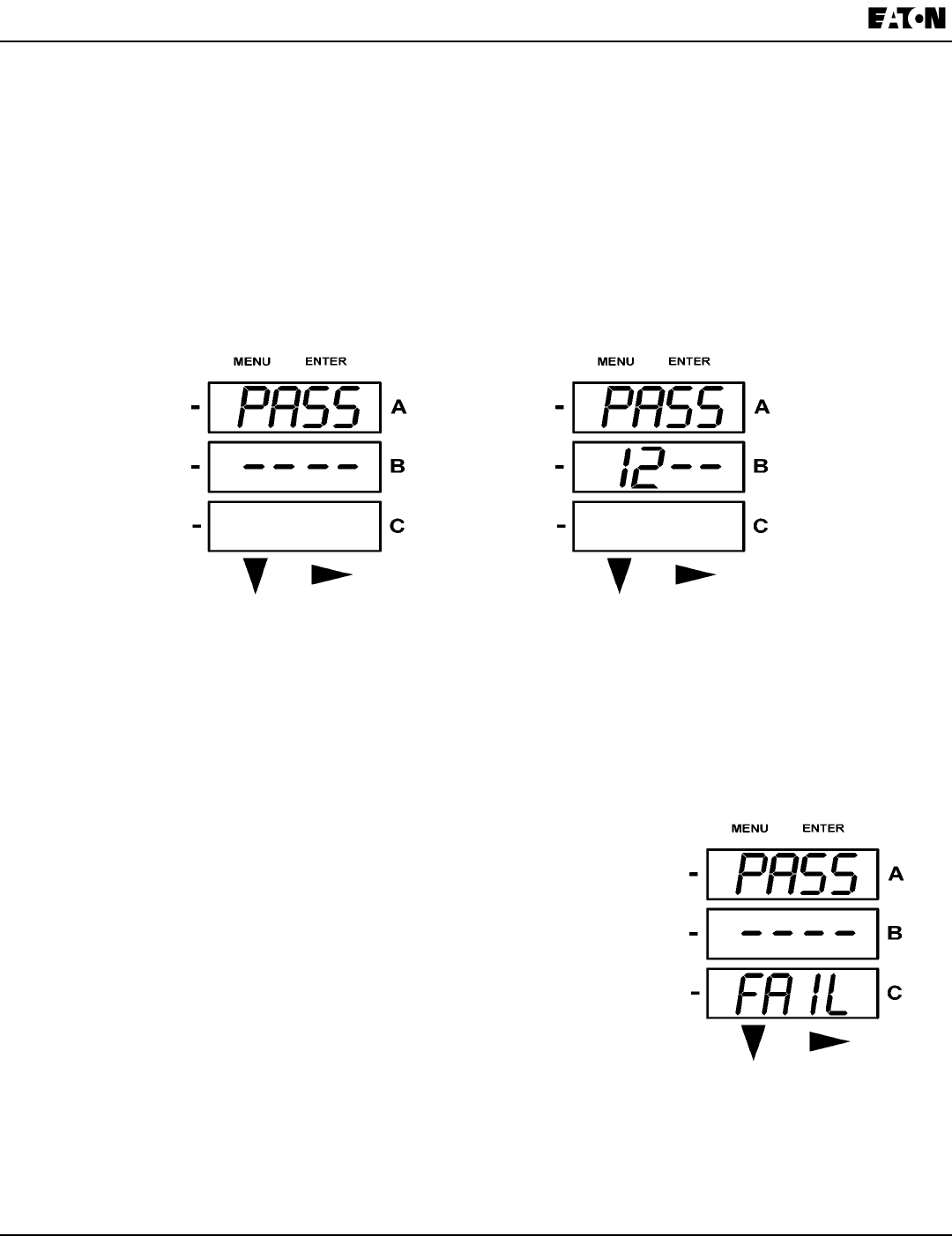
Entering a Password
IfPasswordProtectionhasbeenenabledinthesoftwareforResetand/orConguration(seeChapter8for
information),ascreenappearsrequestingaPasswordwhenyoutrytoresetthemeterand/orconguresettings
throughthefrontpanel.
•PASSappearsintheAwindowand4dashesappearintheBwindow.Theleftmost dashisashing.
1. Press the Downbuttontoscrollnumbersfrom0to9fortheashingdash.Whenthecorrectnumber
appears for that dash, use the the Rightbuttontomovetothenextdash.
Example:Theleftscreen,below,showsfourdashes.Therightscreenshowsthedisplayaftertherst
twodigitsofthepasswordhavebeenentered.
2.Whenall4digitsofthepasswordhavebeenselected,presstheEnterbutton.
•IfyouareinReset ModeandthecorrectPasswordhasbeenentered,“rSt dMd donE”or“rSt EnEr
donE”appearsandthescreenresumesauto-scrollingparameters.
• IfyouareinConguration ModeandthecorrectPasswordhasbeenentered,thedisplayreturnstothe
screenthatrequiredapassword.
•IfanincorrectPasswordhasbeenentered,“PASS ---- FAIL”appears,and:
•Thepreviousscreenisredisplayed,ifyouareinReset Mode.
•ThepreviousOperatingModescreenisredisplayed,ifyouarein
Conguration Mode.
Chapter 6:
IQ 250/260 Meter Using the IQ 250/260
www.eaton.com IB02601006E 6-5
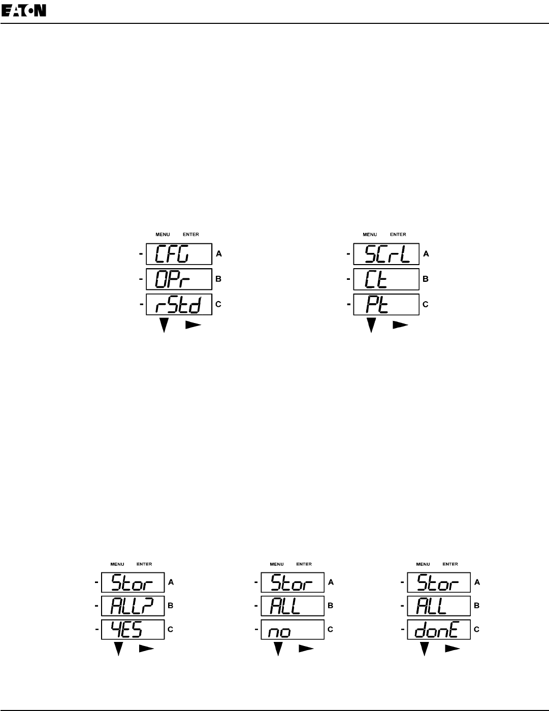
Using Conguration Mode
Conguration ModefollowsReset:EnergyontheMainMenu.
To access Conguration Mode:
1. Press the Menubuttonwhilethemeterisauto-scrollingparameters.
2. Press the DownbuttonuntiltheCongurationModeoption(CFG)isintheAwindow.
3. Press the Enter button.TheConguration Parameters screen appears.
4. Press the Downbuttontoscrollthroughthecongurationparameters:Scroll (SCrL), CT, PT, Connection
(Cnct) and Port.Theparametercurrently‘Active,”i.e.,congurable,ashesintheAwindow.
5. Press the EnterbuttontoaccesstheSettingscreenforthecurrentlyactiveparameter.
NOTE:You can use the Enter button to scroll through all of the Conguration parameters and their
Setting screens, in order.
Press Enter when CFG is in A window - Parameter screen appears - Press Down-
Press Enter when Parameter you want is in A window
6.Theparameterscreenappears,showingthecurrentsettings.Tochangethesettings:
•UseeithertheDownbuttonortheRightbuttontoselectanoption.
•Toenteranumbervalue,usetheDownbuttontoselectthenumbervalueforadigitandtheRightbutton
tomovetothenextdigit.
NOTE: WhenyoutrytochangethecurrentsettingandPasswordProtectionisenabledforthemeter,the
Passwordscreenappears.See the previous page for instructions on entering a password.
7.Onceyouhaveenteredthenewsetting,presstheMenubuttontwice.
8. The Store ALL YESscreenappears.Youcaneither:
•PresstheEnterbuttontosavethenewsetting.
•PresstheRight buttontoaccesstheStore ALL no screen;thenpresstheEnterbuttontocanceltheSave.
9.Ifyouhavesavedthesettings,theStore ALL done screen appears and the meter resets.
Press the Enter button to save the settings Press the Enter button to The settings have been saved

6-6 IB02601006E www.eaton.com
Chapter 6:
Using the IQ 250/260 IQ 250/260 Meter
Conguring the Scroll Feature
WheninAuto Scrollmode,themeterperformsascrollingdisplay,showingeachparameterfor7seconds,witha1
secondpausebetweenparameters.Theparametersthatthemeterdisplaysaredeterminedbythefollowing
conditions:
•Theyhavebeenselectedthroughsoftware.(RefertoChapter8forinstructions.)
•WhetheryourmetermodelisanIQ250orIQ260.
To enable or disable Auto-scrolling:
1. Press the EnterbuttonwhenSCrl isintheAwindow.
The Scroll YES screen appears.
2. Press either the Right or Down buttonifyouwanttoaccessthe
Scroll no screen.
To return to the Scoll YESscreen,presseitherbutton.
3. Press the EnterbuttononeithertheScroll YES screen(toenableauto-scrolling)ortheScroll no screen
(todisableauto-scrolling).
The CT- nscreenappears(thisisthenextCongurationmodeparameter).
NOTE:
• To exitthescreenwithoutchangingscrollingoptions,presstheMenubutton.
•ToreturntotheMainMenuscreen,presstheMenubuttontwice.
•Toreturntothescrolling(ornon-scrolling)parametersdisplay,presstheMenubuttonthreetimes.

Chapter 6:
IQ 250/260 Meter Using the IQ 250/260
www.eaton.com IB02601006E 6-7
Conguring CT Setting
TheCTSettinghasthreeparts:Ct-n (numerator),Ct-d(denominator),andCt-S(scaling).
1. Press the EnterbuttonwhenCtisintheAwindow.
The Ct-nscreenappears.Youcaneither:
•ChangethevaluefortheCTnumerator.
•AccessoneoftheotherCTscreensbypressingtheEnterbutton:pressEnteroncetoaccesstheCt-d
screen,twicetoaccesstheCt-S screen.
NOTE: The Ct-d screen is preset to a 5 amp or 1 amp value at the factory and cannot be changed.
a. To change the value for the CT numerator
From the Ct-n screen:
•UsetheDownbuttontoselectthenumbervalueforadigit.
•UsetheRightbuttontomovetothenextdigit.
b. To change the value for CT scaling
From the Ct-S screen:
UsetheRightbuttonortheDownbuttontochoosethescalingyouwant.TheCt-Ssettingcanbe1, 10, or
100.
NOTE: If you are prompted to enter a password, refer to the instructions earlier in the chapter.
2.Whenthenewsettingisentered,presstheMenubuttontwice.
3. The Store ALL YES screen appears. Press EntertosavethenewCTsetting.
Example CT Settings:
200/5Amps: SettheCt-nvaluefor200andtheCt-Svaluefor1.
800/5Amps: SettheCt-nvaluefor800andtheCt-Svaluefor1.
2,000/5Amps: SettheCt-nvaluefor2000andtheCt-Svaluefor1.
10,000/5Amps: SettheCt-nvaluefor1000andtheCt-Svaluefor10.
NOTES:
• ThevalueforAmpsisaproductoftheCt-nvalueandtheCt-Svalue.
•Ct-nandCt-Saredictatedbyprimarycurrent;Ct-dissecondarycurrent.
Press Enter Use buttons to set Ct-n value The Ct-d cannot be changed Use buttons to select scaling
6-8 IB02601006E www.eaton.com
Chapter 6:
Using the IQ 250/260 IQ 250/260 Meter
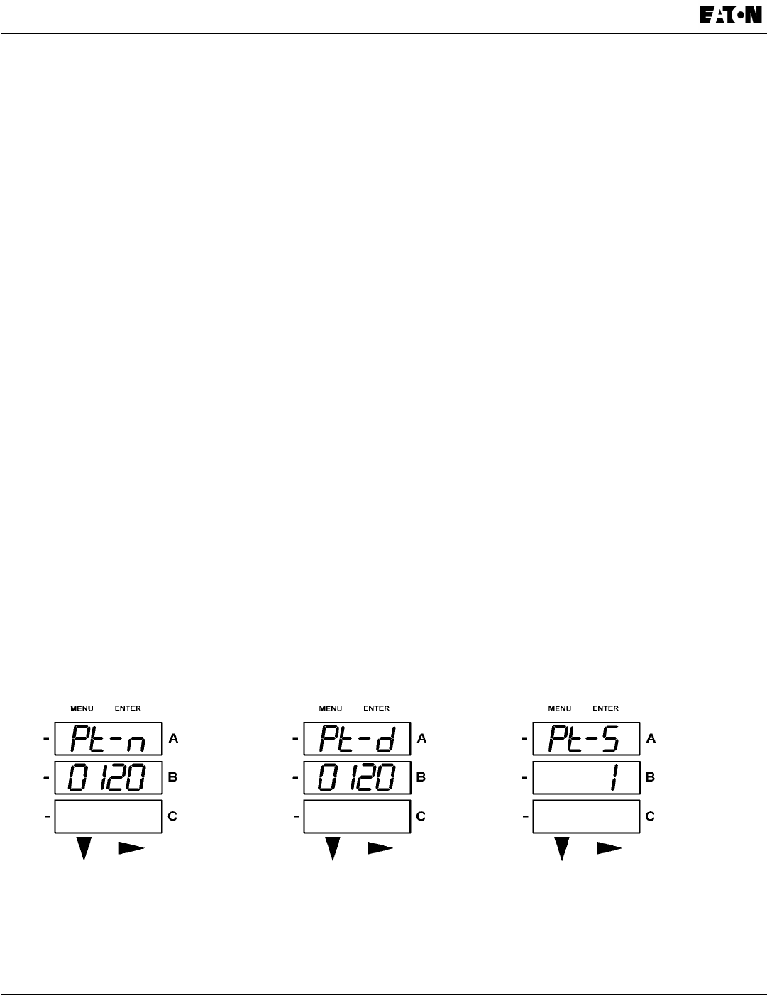
Conguring PT Setting
ThePTSettinghasthreeparts:Pt-n (numerator),Pt-d(denominator),andPt-S(scaling).
1. Press the Enter buttonwhenPtisintheAwindow.
The PT-n screenappears.Youcaneither:
•ChangethevalueforthePTnumerator.
•AccessoneoftheotherPTscreensbypressingtheEnterbutton:pressEnter once to access the Pt-d
screen,twicetoaccessthePt-S screen.
a. To change the value for the PT numerator or denominator
From the Pt-n or Pt-d screen:
• UsetheDown buttontoselectthenumbervalueforadigit.
•UsetheRightbuttontomovetothenextdigit.
b. To change the value for the PT scaling
From the Pt-S screen:
UsetheRightbuttonortheDownbuttontochoosethescalingyouwant.ThePt-Ssettingcanbe1, 10,
100, or 1000.
NOTE: If you are prompted to enter a password, refer to the instructions earlier in this chapter.
2.Whenthenewsettingisentered,pressthe Menu buttontwice.
3. The STOR ALL YES screenappears.PressEntertosavethenewPTsetting.
Example Settings:
277/277Volts: Pt-nvalueis277,Pt-dvalueis277,Pt-Svalueis1.
14,400/120Volts: Pt-nvalueis1440,Pt-dvalueis120,Pt-Svalueis10.
138,000/69Volts: Pt-nvalueis1380,Pt-dvalueis69,Pt-Svalueis100.
345,000/115Volts: Pt-nvalueis3450,Pt-dvalueis115,Pt-Svalueis100.
345,000/69Volts: Pt-nvalueis345,Pt-dvalueis69,Pt-Svalueis1000.
NOTE: Pt-nandPt-Saredictatedbyprimaryvoltage;Pt-dissecondaryvoltage.
Use buttons to set Pt-n value Use buttons to set Pt-d value Use buttons to select scaling
Chapter 6:
IQ 250/260 Meter Using the IQ 250/260
www.eaton.com IB02601006E 6-9
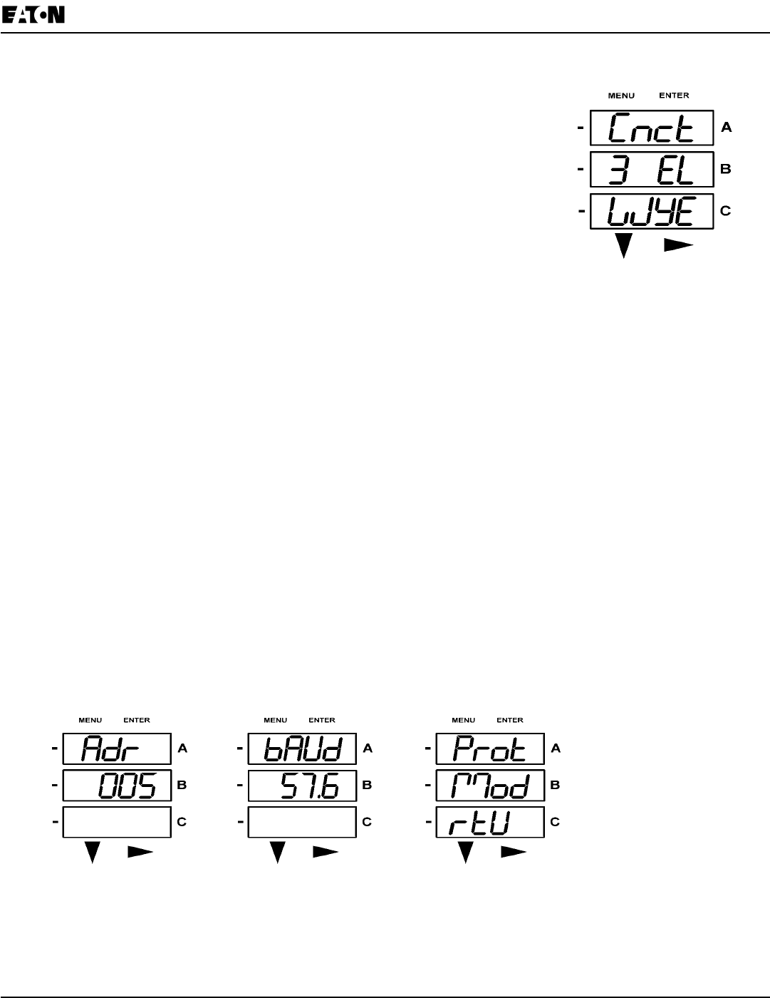
Conguring Connection Setting
1. Press the EnterbuttonwhenCnctisintheAwindow.TheCnct screen appears.
2. Press the Right button or Down buttontoselectaconguration.
Thechoicesare:
•3ElementWye(3 EL WYE)
•2.5ElementWye(2.5EL WYE)
•2CTDelta(2 Ct dEL)
NOTE: If you are prompted to enter a password, refer to the instructions
earlier in this chapter.
3.Whenyouhavemadeyourselection,presstheMenubuttontwice.
4. The STOR ALL YES screen appears. Press Enter tosavethesetting. Use buttons to select conguration
Conguring Communication Port Setting
Portcongurationconsistsof:Address(athreedigitnumber),Baud Rate(9600;19200;38400;or57600),and
Protocol(DNP3.0;ModbusRTU;orModbusASCII).
1. Press the EnterbuttonwhenPOrtisintheAwindow.
The Adr(address)screenappears.Youcaneither:
•Entertheaddress.
•AccessoneoftheotherPortscreensbypressingtheEnterbutton:pressEnter once to access the bAUd
screen(BaudRate);pressEntertwicetoaccesstheProtscreen(Protocol).
a. To enter the Address, from the Adr screen:
• UsetheDown buttontoselectthenumbervalueforadigit.
•UsetheRightbuttontomovetothenextdigit.
b.To select the Baud Rate, from the bAUd screen:
UsetheRightbuttonortheDownbuttontoselectthesettingyouwant.
c. To select the Protocol, from the Prot screen:
Press the Right buttonorthe Downbuttontoselectthesettingyouwant.
NOTE: If you are prompted to enter a password, refer to the instructions earlier in this chapter.
2.Whenyouhavenishedmakingyourselections,presstheMenubuttontwice.
3. The STOR ALL YES screen appears. Press Entertosavethesettings.
Use buttons to enter Address Use buttons to select Baud Rate Use buttons to select Protocol

6-10 IB02601006E www.eaton.com
Chapter 6:
Using the IQ 250/260 IQ 250/260 Meter
Using Operating Mode
Operating ModeistheIQ250/260meter’sdefaultmode,thatis,thestandardfrontpaneldisplay.AfterStartup,
themeterautomaticallyscrollsthroughtheparameterscreens,ifscrollingisenabled.Eachparameterisshownfor
7seconds,witha1secondpausebetweenparameters.Scrollingissuspendedfor3minutesafteranybuttonis
pressed.
1. Press the DownbuttontoscrollalltheparametersinOperating Mode.Thecurrently“Active,”i.e.,displayed,
parameterhastheIndicatorlightnexttoit,ontherightfaceofthemeter.
2. Press the Rightbuttontoviewadditionalreadingsforthatparameter.Thetablebelowshowspossible
readingsforOperatingMode.Sheet 2 in
AppendixA
showstheOperatingModeNavigationMap.
NOTE: Readingsorgroupsofreadingsareskippedifnotapplicabletothemetertypeorhookup,orif
theyaredisabledintheprogrammablesettings.
OPERATING MODE PARAMETER READINGS
POSSIBLE READINGS
VOLTS L-N VOLTS_LN VOLTS_LN_
MAX VOLTS_LN_
MIN VOLTS_LN_
THD
VOLTS L-L VOLTS_LL VOLTS_LL_
MAX VOLTS_LL_
MIN
AMPS AMPS AMPS_
NEUTRAL AMPS_
MAX AMPS_MIN AMPS_THD
W/VAR/PF W_VAR_PF W_VAR_
PF_MAX_
POS
W_VAR_
PF_MIN_
POS
W_VAR_
PF_MIN_
NEG
VA/Hz VA_FREQ VA_FREQ_
MAX VA_FREQ_
MIN
Wh KWH_REC KWH_DEL KWH_NET KWH_TOT
VARh KVARH_
POS KVARH_
NEG KVARH_
NET KVARH_
TOT
VAh KVAH

Chapter 6:
IQ 250/260 Meter Using the IQ 250/260
www.eaton.com IB02601006E 6-11
Understanding the % of Load Bar
The10-segmentLEDbargraphatthebottomleftoftheIQ250/260frontpanelprovidesagraphicrepresentationof
Amps.Thesegmentslightaccordingtotheload,asshowninthe%LoadSegmentTablebelow.
WhentheLoadisover120%ofFullLoad,allsegmentsash“On”(1.5secs)and“Off”(0.5secs).
% of Load Segment Table
Segments
Load >= % Full Load
none no load
1 1%
1-2 15%
1-3 30%
1-4 45%
1-5 60%
1-6 72%
1-7 84%
1-8 96%
1-9 108%
1-10 120%
All Blink >120%
6-12 IB02601006E www.eaton.com
Chapter 6:
Using the IQ 250/260 IQ 250/260 Meter
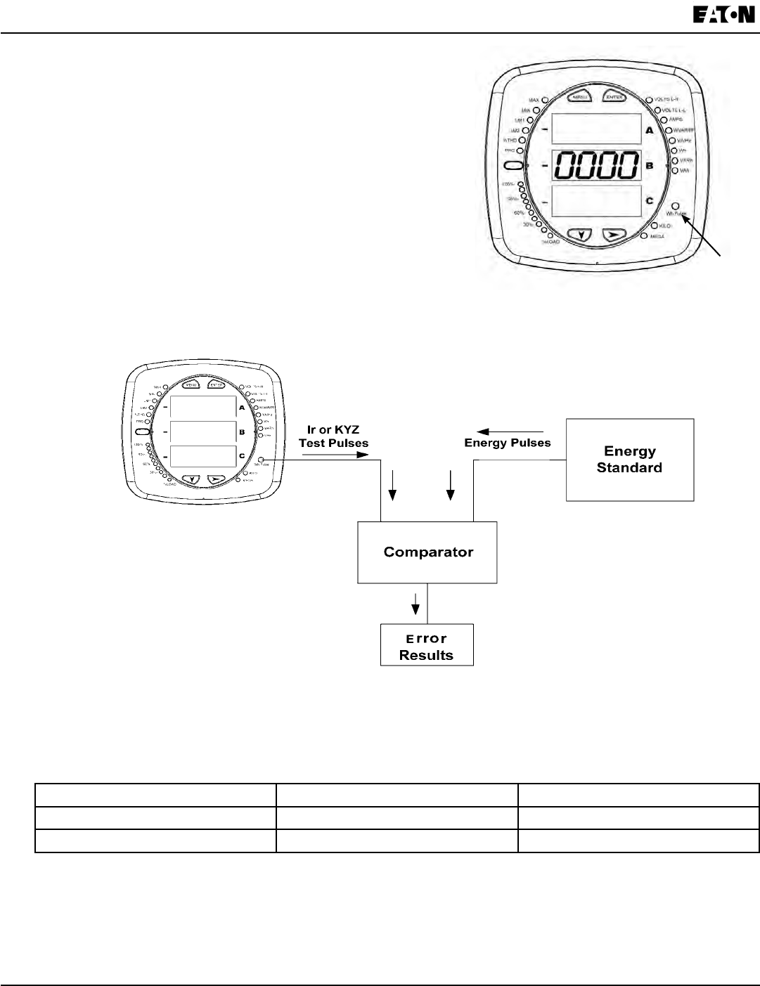
Performing Watt-Hour Accuracy Testing (Verication)
To be certied for revenue metering, power providers
and utility companies must verify that the billing energy
meter performs to the stated accuracy. To conrm the
meter’s performance and calibration, power providers use
eld test standards to ensure that the unit’s energy
measurements are correct. Since the IQ 250/260 is a
traceable revenue meter, it contains a utility grade test pulse
that can be used to gate an accuracy standard. This is an
essential feature required of all billing grade meters.
• Refer to Figure 6.5 for an example of how this process works.
• Refer to Table 6.1 for the Wh/Pulse Constants for Accuracy Testing.
Table6.1:Infrared&KYZPulseConstantsforAccuracyTesting-KhWatthourperpulse
Input Voltage Level Class 10 Models Class 2 Models
Below 150V 0.500017776 0.1000035555
Above 150V 2.000071103 0.400014221
NOTE: Minimumpulsewidthis90milliseconds.
Figure 6.5: Using the Watt-Hour Test Pulse
Figure 6.4: Watt-Hour Test Pulse
Watt-Hour
Test Pulse
Chapter 7:
IQ 250/260 Meter Using the I/O Option Cards
www.eaton.com IB02601006E 7-1
7 UsingtheI/OOptionCards
Overview
The IQ 250/260 offers extensive I/O expandability. UsingthetwouniversalOptionCardslots,theunitcanbe
easilyconguredtoacceptnewI/OOptioncardsevenafterinstallation,withoutyourneedingtoremoveitfromthe
installation.TheIQ250/260auto-detectsanyinstalledOptioncards.Upto2modulesofanytypeoutlinedinthis
chaptercanbeusedpermeter.
Option Card Slots
I/ Option Card
Figure 7.1: IQ 250/260 Back Showing Option Card Slots and I/O Card
7-2 IB02601006E www.eaton.com
Chapter 7:
Using the I/O Option Cards IQ 250/260 Meter
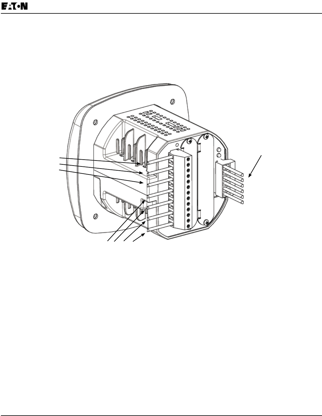
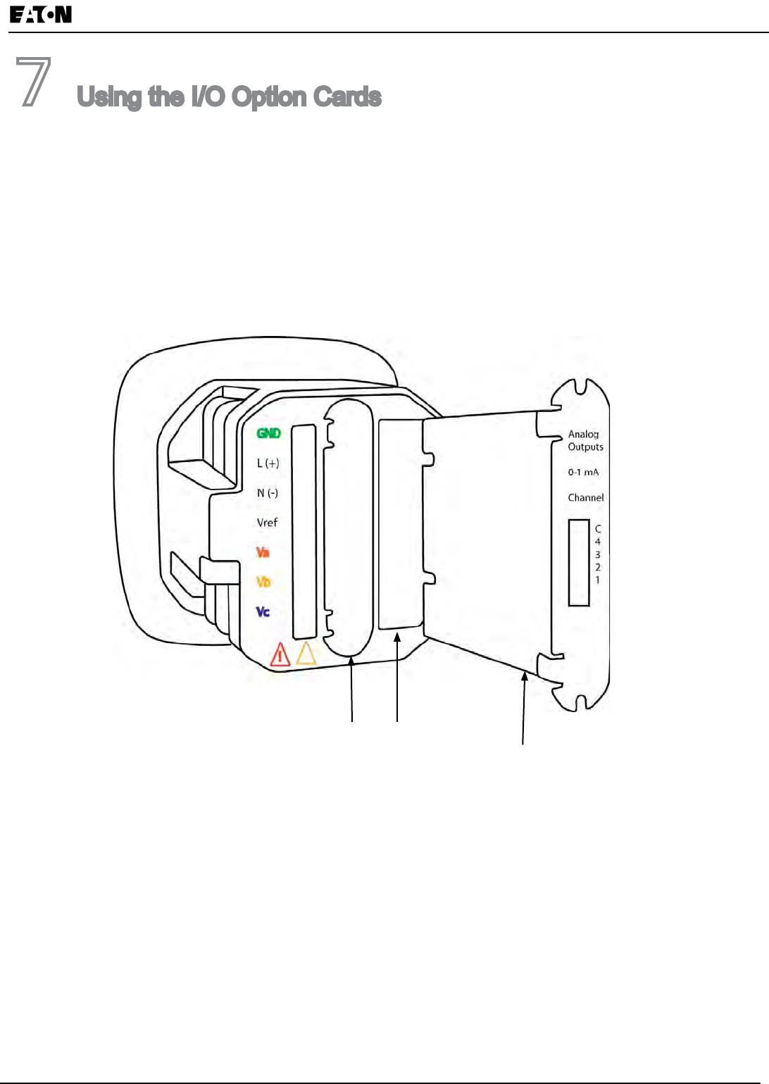
Installing Option Cards
TheOptionCardsareinsertedinoneofthetwoOptionCardslotsinthebackoftheIQ250/260.
Note: RemoveVoltageInputsandpowersupplyterminaltotheIQ250/260beforeperformingcardinstallation.
1.RemovethescrewsatthetopandthebottomoftheOptionCardslotcovers.
2.Thereisaplastic“track”onthetopandthebottomoftheslot.TheOptioncardtsintothistrack.
WARNING!
For safety,
remove these
connections
before
installing
Option
Cards (GND,
L, N, Vref,
Va, Vb, Vc)
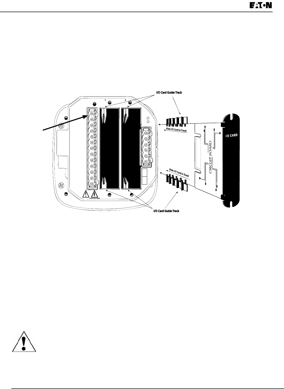
3.Slidethecardinsidetheplastictrackandinsertitintotheslot.Youwillhearaclickwhenthecard
isfullyinserted.Be careful,itiseasytomisstheguidetrack.
CAUTIONS!
•MakesuretheI/Ocardisinsertedproperlyintothetracktoavoiddamagingthecard’scomponents.
•Forpropertofcards,andtoavoiddamagingtheunit,insertcomponentsinthefollowingorder:
1.OptionCard1
2.OptionCard2
3.Detachableterminalblock1
4.Detachableterminalblock2
5.CommunicationconnectionforRS485Port
Conguring Option Cards
CAUTION! FOR PROPER OPERATION, RESET ALL PARAMETERS IN THE UNIT AFTER
HARDWARE MODIFICATION.
TheIQ250/260auto-detectsanyOptioncardsinstalledinit.YouconguretheOptioncardsthroughsoftware.
RefertoChapter8forinstructions.
I/O Card Guide Track
I/O Card Guide Track
GND
Tx
Rx
SH
+
-
RS485
KYZNC
NO
C
L (+)
L (-)
Vref
Va
Vb
Vc
Figure 7.2: Detail of Guide Tracks

Chapter 7:
IQ 250/260 Meter Using the I/O Option Cards
www.eaton.com IB02601006E 7-3
The following sections describe the available Option cards.
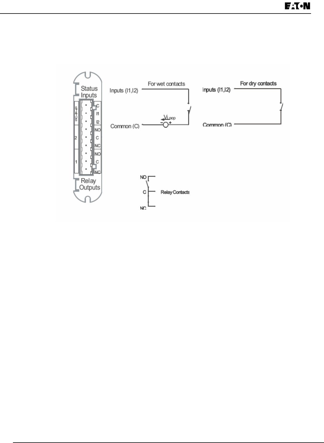
Digital Output (Relay Contact) / Digital Input Card (IQ250/260-IO1)
TheDigitalOutput/Inputcardisacombinationofrelaycontactoutputsforloadswitchinganddry/wetcontactsensing
digitalinputs.Theoutputsareelectricallyisolatedfromtheinputsandfromthemainunit.
Specications
The technical specications at 25 °C are as follows:
Powerconsumption: 0.320Winternal
Relayoutputs.
Numberofoutputs: 2
Contacttype: Changeover(SPDT)
Relaytype: Mechanicallylatching
Switchingvoltage: AC250V/DC30V
Switchingpower: 1250VA/150W
Switchingcurrent: 5A
Switchingratemax.: 10/s
Mechanicallife: 5x10⁷switchingoperations
Electricallife: 105switchingoperationsatratedcurrent
Breakdownvoltage: AC1000Vbetweenopencontacts
Isolation: AC3000V/5000Vsurgesystemtocontacts
Reset/Powerdownstate: Nochange-laststateisretained
Inputs.
NumberofInputs: 2
Sensingtype: Wetordrycontactstatusdetection
Wettingvoltage: DC12V,internallygenerated
Inputcurrent: 2.5mA–constantcurrentregulated
Minimuminputvoltage: 0V(inputshortedtocommon)
Maximuminputvoltage: DC150V(diodeprotectedagainstpolarityreversal)
Filtering: De-bouncingwith50msdelaytime
Detectionscanrate: 100ms
Isolation: AC2500Vsystemtoinputs
The general specications are as follows:
Operatingtemperature: (-20to+70)°C
Storagetemperature: (-40to+80)°C
Relativeairhumidity: Maximum95%,non-condensing
EMC-ImmunityInterference: EN61000-4-2
Weight: 1.5oz
Dimensions(inch)WxHxL: 0.72x2.68x3.26
ExternalConnection: AWG12-26/(0.129-3.31)mm2
9pin,0.200”pluggableterminalblock
7-4 IB02601006E www.eaton.com
Chapter 7:
Using the I/O Option Cards IQ 250/260 Meter
Wiring Diagram
Fig. 7.3: Relay Contact (2) / Status Input (2) Card
Relay card
Pulse card

Chapter 7:
IQ 250/260 Meter Using the I/O Option Cards
www.eaton.com IB02601006E 7-5
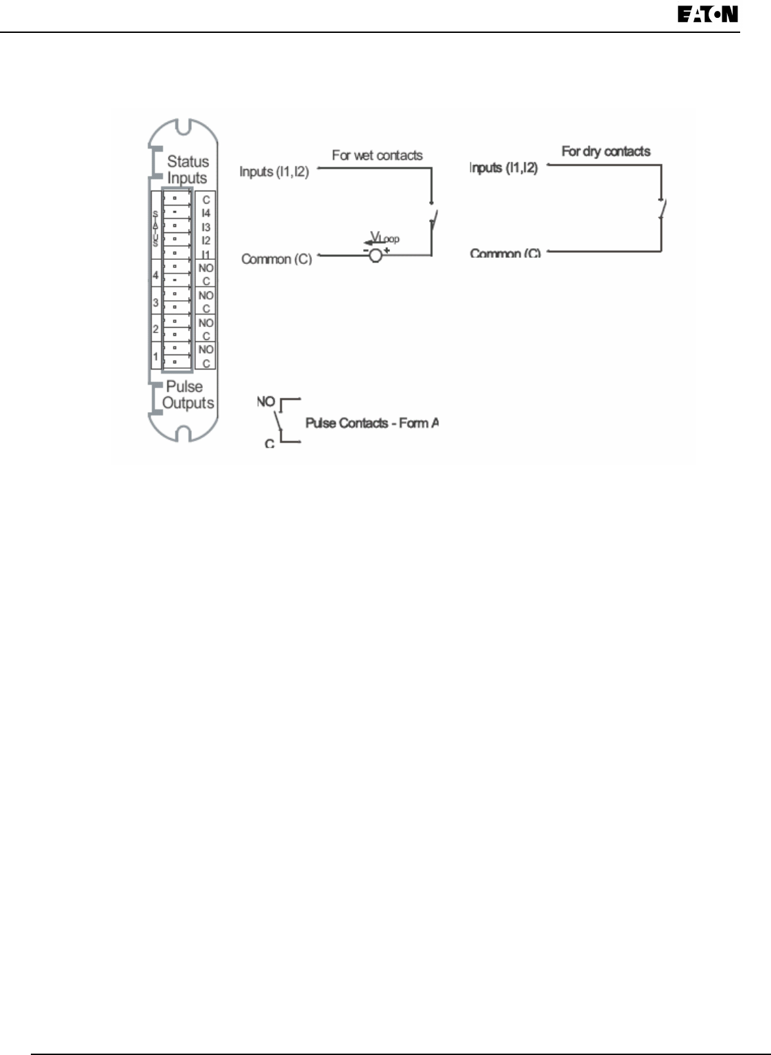
Pulse Output (Solid State Relay Contacts) / Digital Input Card (IQ250/260-IO2)
ThePulseOutput/DigitalInputcardisacombinationofpulseoutputsviasolidstatecontactsanddry/wetcontact
sensingdigitalinputs.Theoutputsareelectricallyisolatedfromtheinputsandfromthemainunit.
Specications
The technical specications at 25 °C are as follows:
Powerconsumption: 0.420Winternal
Relayoutputs
Numberofoutputs: 4
Contacttype: Closing(SPST-NO)
Relaytype: Solidstate
Peakswitchingvoltage: DC±350V
Continuousloadcurrent: 120mA
Peakloadcurrent: 350mAfor10ms
Onresistance,max.: 35Ω
Leakagecurrent: 1µA@350V
SwitchingRatemax.: 10/s
Isolation: AC3750Vsystemtocontacts
Reset/Powerdownstate: Opencontacts
Inputs
Numberofinputs: 4
Sensingtype: Wetordrycontactstatusdetection
Wettingvoltage: DC12V,internallygenerated
Inputcurrent: 2.5mA–constantcurrentregulated
Minimuminputvoltage: 0V(inputshortedtocommon)
Maximuminputvoltage: DC150V(diodeprotectedagainstpolarityreversal)
Filtering: De-bouncingwith50msdelaytime
Detectionscanrate: 100ms
Isolation: AC2500Vsystemtoinputs
The general specications are as follows:
OperatingTemperature: (-20to+70)°C
StorageTemperature: (-40to+80)°C
Relativeairhumidity: Maximum95%,non-condensing
EMC-ImmunityInterference: EN61000-4-2
Weight: 1.3oz
Dimensions(inch)WxHxL: 0.72x2.68x3.26
ExternalConnection: AWG12-26/(0.129-3.31)mm2
13pin,3.5mmpluggableterminalblock
Default Conguration:
TheIQ250/260automaticallyrecognizestheinstalledoptioncardduringPowerUp.Ifyouhavenotprogrammeda
congurationforthecard,theunitwilldefaulttothefollowingoutputs:
Status Inputs DefaultedtoStatusDetect
Pulse Outputs DefaultedtoEnergyPulses
Pulse Channel 1 1.8+Watt-hrsperpulse
Pulse Channel 2 1.8-Watt-hrsperpulse
Pulse Channel 3 1.8+VAR-hrsperpulse
Pulse Channel 4 1.8-VAR-hrsperpulse
7-6 IB02601006E www.eaton.com
Chapter 7:
Using the I/O Option Cards IQ 250/260 Meter
Wiring Diagram
Fig. 7.4: Pulse Output (4) / Status Input (4) Card
Relay card
Pulse card

Chapter 7:
IQ 250/260 Meter Using the I/O Option Cards
www.eaton.com IB02601006E 7-7
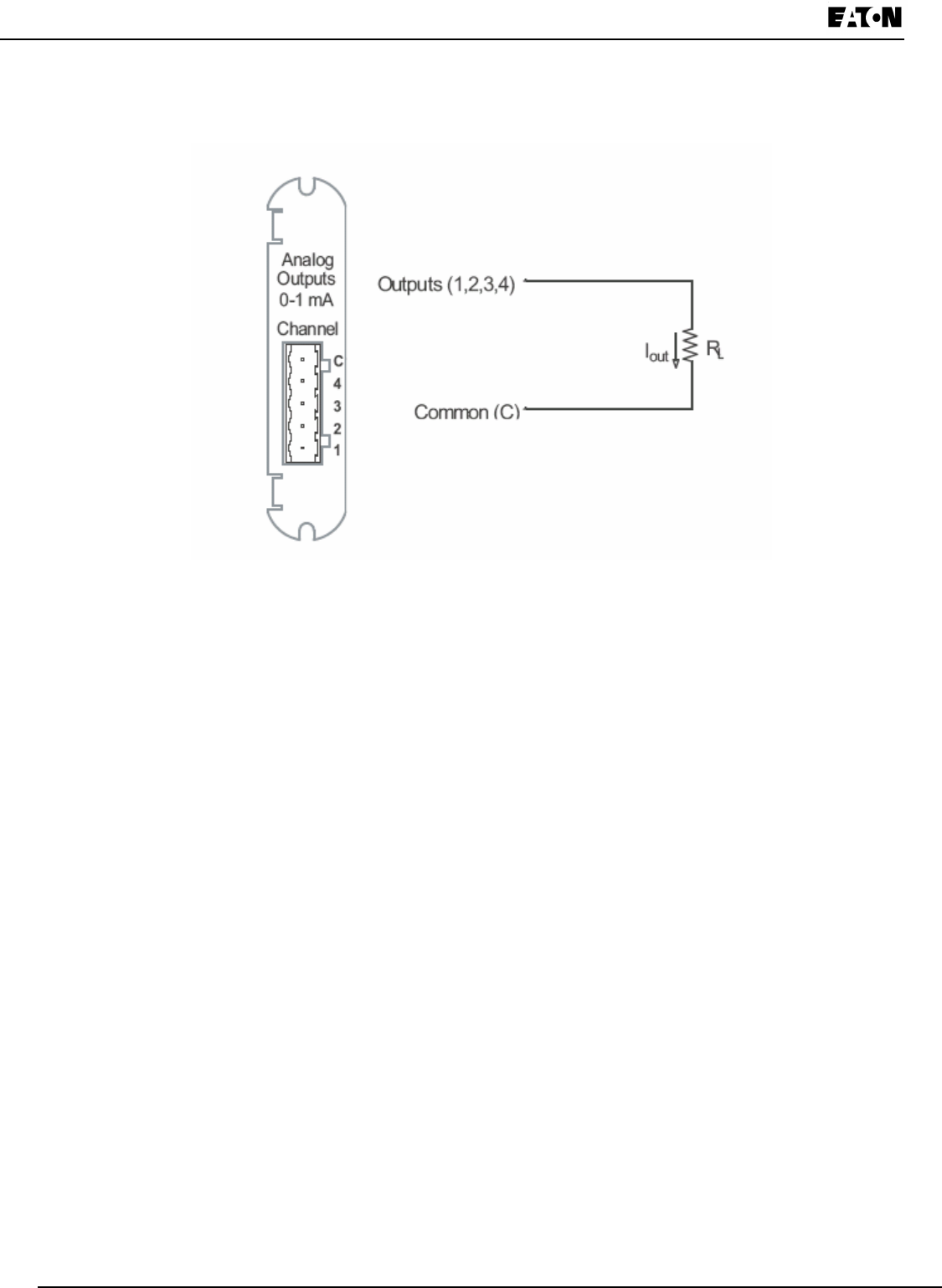
1mA Output Card (IQ250/260-IO3)
The1mAcardtransmitsastandardizedbi-directional0-1mAsignal.Thissignalislinearlyproportionaltoreal-time
quantitiesmeasuredbytheIQ250/260meter.Theoutputsareelectricallyisolatedfromthemainunit.
Specications:
The technical specications at 25° C at 5kΩ load are as follows:
Numberofoutputs: 4singleended
Powerconsumption: 1.2Winternal
Signaloutputrange: (-1.2to+1.2)mA
Max.loadimpedance: 10kΩ
Hardwareresolution: 12bits
Effectiveresolution: 14bitswith2.5kHzPWM
Updaterateperchannel: 100ms
Outputaccuracy: ±0.1%ofoutputrange(2.4mA)
Loadregulation ±0.06%ofoutputrange(2.4mA)loadstepof5kΩ@±1mA
Temperaturecoefcient ±30nA/°C
Isolation: AC2500Vsystemtooutputs
Reset/Defaultoutputvalue: 0mA
The general specications are as follows:
Operatingtemperature: (-20to+70)°C
Storagetemperature: (-40to+80)°C
Relativeairhumidity: Maximum95%,non-condensing
EMC-ImmunityInterference: EN61000-4-2
Weight: 1.6oz
Dimensions(inch)WxHxL: 0.72x2.68x3.26
Externalconnection: AWG12-26/(0.29-3.31)mm2
5pin,0.200”pluggableterminalblock
Default Conguration:
TheIQ250/260automaticallyrecognizestheinstalledoptioncardduringPowerUp.Ifyouhavenotprogrammeda
congurationforthecard,theunitwilldefaulttothefollowingoutputs:
Channel 1 +Watts,+1800Watts=>+1mA
-Watts,-1800Watts=>-1mA
Channel 2 +VARs,+1800VARs=>+1mA
-VARs,-1800VARs=>-1mA
Channel 3PhaseAVoltageWYE,300Volts=>+1mA
PhaseAVoltageDelta,600Volts=>+1mA
Channel 4 PhaseACurrent,10Amps=>+1mA
7-8 IB02601006E www.eaton.com
Chapter 7:
Using the I/O Option Cards IQ 250/260 Meter
Wiring Diagram
Fig 7.5: 4-Channel 0 - 1mA Output Card
0-1mA
0-20mA

Chapter 7:
IQ 250/260 Meter Using the I/O Option Cards
www.eaton.com IB02601006E 7-9
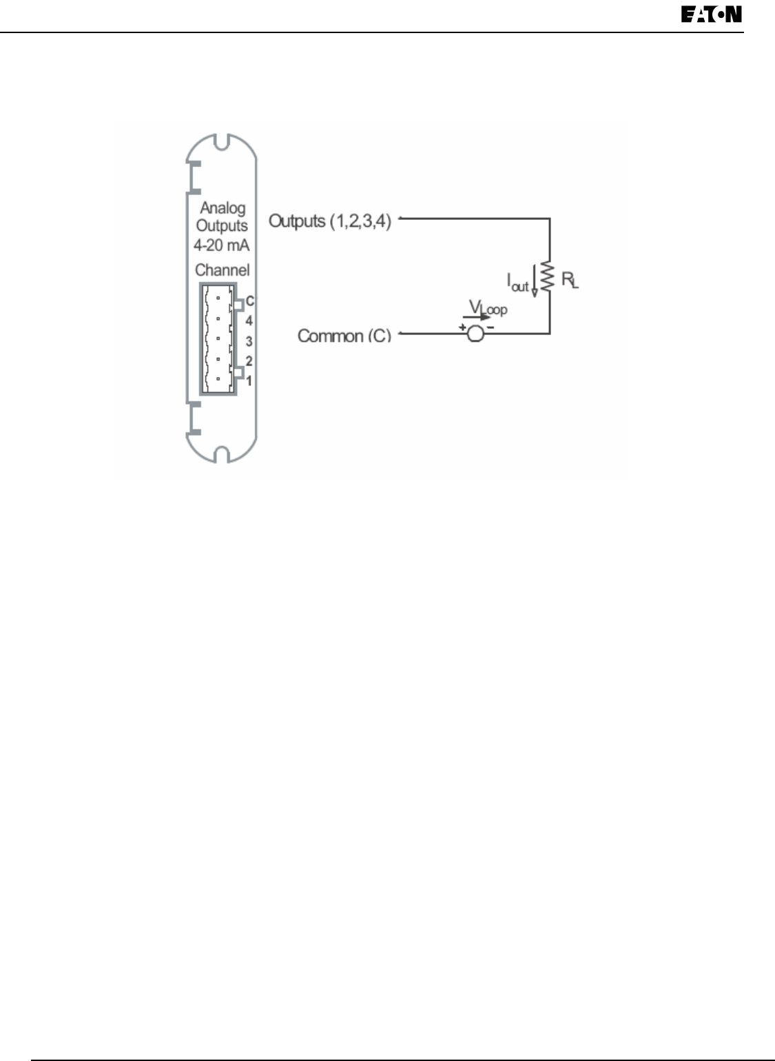
20mA Output Card (IQ250/260-IO4)
The20mAcardtransmitsastandardized0-20mAsignal.Thissignalislinearlyproportionaltoreal-timequantities
measuredbytheIQ250/260.The current sources need to be loop powered.Theoutputsareelectricallyisolated
from the main unit.
Specications
The technical specications at 25° C at 500Ω load are as follows:
Numberofoutputs: 4singleended
Powerconsumption: 1Winternal
Signaloutputrange: (0to24)mA
Max.loadimpedance: 850Ω@24VDC
Hardwareresolution: 12bits
Effectiveresolution: 14bitswith2.5kHzPWM
Updaterateperchannel: 100ms
Outputaccuracy: ±0.1%ofoutputrange(24mA)
Loadregulation: ±0.03%ofoutputrange(24mA)loadstepof200Ω@20mA
Temperaturecoefcient ±300nA/°C
Isolation: AC2500Vsystemtooutputs
Maximumloopvoltage: 28Vdcmax
Internalvoltagedrop: 3.4VDC@24mA
Reset/Defaultoutputvalue: 12mA
The general specications are as follows:
Operatingtemperature: (-20to+70)°C
Storagetemperature: (-40to+80)°C
Relativeairhumidity: Maximum95%,non-condensing
EMC-Immunityinterference: EN61000-4-2
Weight: 1.6oz
Dimensions(inch)WxHxL: 0.72x2.68x3.26
Externalconnection: AWG12-26/(0.129-3.31)mm2
5pin,0.200”pluggableterminalblock
Default Conguration:
TheIQ250/260automaticallyrecognizestheinstalledoptioncardduringPowerUp.Ifyouhavenotprogrammeda
congurationforthecard,theunitwilldefaulttothefollowingoutputs:
Channel 1 +Watts,+1800Watts=>20mA
-Watts,-1800Watts=>4mA
0Watts=>12mA
Channel 2 +VARs,+1800VARs=>20mA
-VARs,-1800VARs=>4mA
0VARs=>12mA
Channel 3PhaseAVoltageWYE,300Volts=>20mA
0Volts=>4mA
PhaseAVoltageDelta,600Volts=>20mA
Channel 4 PhaseACurrent,10Amps=>20mA
0PhaseACurrent,0Amps=>4mA
7-10 IB02601006E www.eaton.com
Chapter 7:
Using the I/O Option Cards IQ 250/260 Meter
Wiring Diagram
Fig. 7.6: 4-Channel 4 - 20mA Output Card
0-1mA
0-20mA
Chapter 8:
IQ 250/260 Meter Programming the IQ 250/260
www.eaton.com IB02601006E 8-1
8 Programming the IQ 250/260
Overview
The IQ 250/260 Meter can be congured using either the meter Face Buttons (Menu, Enter, Down and Right) or
Eaton Meter Conguration Software. To connect to the meter for software conguration, use the RS485 port (Com
2) on the back panel of the meter.
The 250/260T must be congured with the Eaton Meter Conguration Software, using the RS485 port, since it does
not have a front panel.
This chapter contains instructions for programming the IQ 250/260 Meter and Transducer using the Eaton Meter
Conguration Software.
Connecting to the IQ 250/260
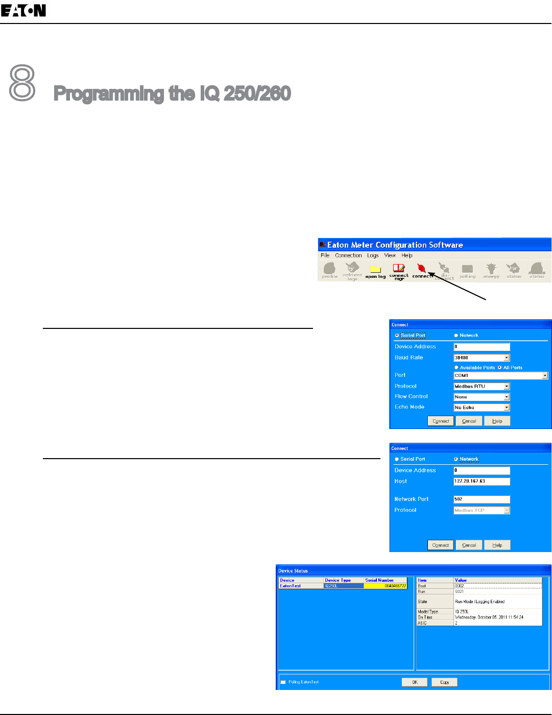
1. Open Eaton Meter Conguration Software.
2. Click the Connect icon on the Title bar or Connection>Quick Connect.
3. If you are connecting to the IQ 250/260 through your PC:
a. Make sure the Serial Port radio button is selected.
b. Enter Device Address (1-247).
c. Select Baud Rate from the pull-down menu.
d. Select the port you are using from the pull-down menu. The
Available Ports/All Ports radio buttons determine which port selections
the menu displays.
e. Select Modbus RTU from the Protocol pull-down menu.
f. Select Flow Control: None or Hardware.
g. Select Echo Mode: No Echo or Static Echo.
If you are connecting to the Meter through the Power Xpert® Gateway:
a. Make sure the Network radio button is selected.
b. Enter Device Address (1-247).
c. Enter the Gateway’s IP Address.
d. Enter Network Port.
e. Protocol defaults to Modbus TCP.
4. Click the Connect button. You will see the Device Status
screen, shown on the right.
NOTE for IQ 250/260 Transducer:
When the IQ 250/260T is powered up, for 10
seconds you can connect to the meter using the
Factory Initial Default Settings (even if the Device
Prole has been changed). After 10 seconds,
the Device Prole reverts to the actual Device Prole
in use.
Factory Initial Default Settings
Baud Rate: 9600
Port: COM1
Protocol: Modbus RTU
8-2 IB02601006E www.eaton.com
Chapter 8:
Programming the IQ 250/260 IQ 250/260 Meter
Accessing the IQ 250/260 Device Prole
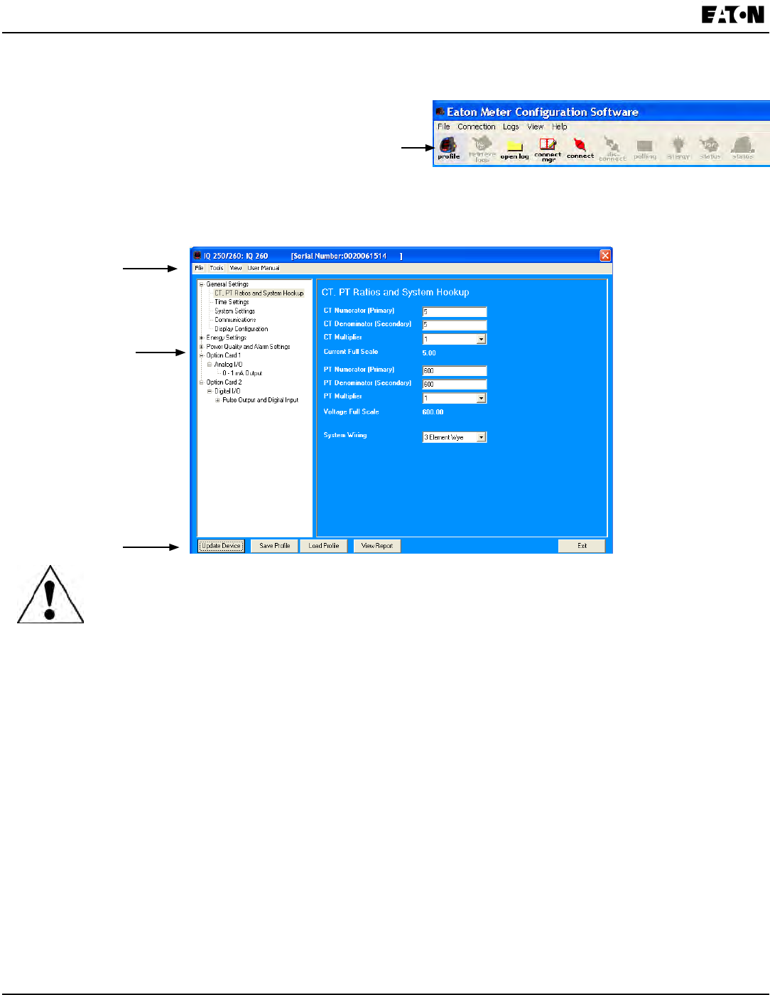
1. Click the Prole icon in the Title Bar.
You will see the IQ 250/260 Device Prole screen.
The Menu on the left side of the screen allows you to
navigate between settings screens (see below).
The Device Prole screen features a Tree Menu for Settings navigation, and Buttons and a
Title Bar that allow you to perform tasks, for example, updating the Device Prole.
Tree Menu,
Listing Settings
Buttons
IMPORTANT! Modication to the Device Prole may cause improper Option Card operation due to
changed Scaling, etc. Verify or update Programmable Settings related to any Option Cards installed in
the meter.
Selecting Settings
n The Tree Menu on the left side of the screen allows you to navigate between Settings. The example screen
pictured above shows the Tree Menu you will see when you rst open the screen. Click on the + next to a
Setting (for example, Power Quality and Alarms Settings) to see additional Setting options.
n From the Tree Menu, click on the Setting you want to congure (for example, Energy Settings) to display its
screen in the right side of the Device Prole screen.
NOTES:
The • Tree Menu you see may look different from that shown in the example screen, because the Option Card
sections of the menu depend on the connected meter’s conguration. That is, if you have Option cards in your
meter, the Settings for those particular Option cards appear in the Tree Menu.
This example screen is for an IQ 260 Meter. The Tree Menu for an IQ 250 Meter does not have • Power Quality
and Alarm Settings.
If your meter has the data logging option (see Chapter 2), you will see a • Trending Proles setting.
Title Bar
Chapter 8:
IQ 250/260 Meter Programming the IQ 250/260
www.eaton.com IB02601006E 8-3
Performing Tasks
You can perform tasks from either the Device Prole screen Buttons or from the Title Bar.
n The screen Buttons and their functions are as follows:
· Update Device: Click to send the current settings to the meter.
NOTE: You must click the Update Device button after making changes to the Settings screens, if you
want to update the connected meter’s settings.
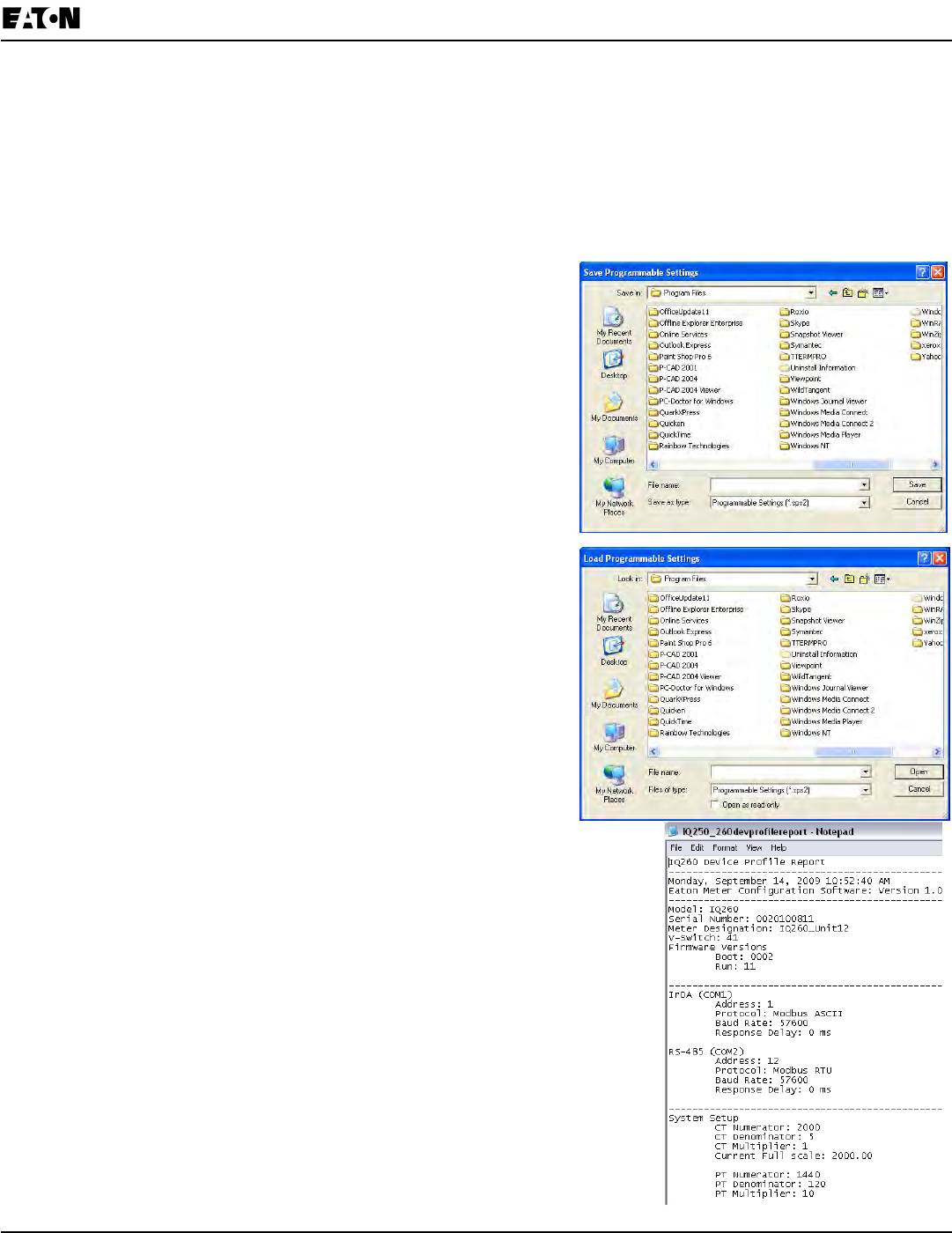
· Save Prole: Click to save the Device Prole settings to
a le. You will see the Save Programmable Settings
window, shown on the right. Give a name to the Device
Prole and click Save.
· Load Prole: Click to load a previously saved Device
Prole Settings le. You will see the Load
Programmable Settings window, shown on the right.
Select the saved Device Prole you want and click Open.
The settings from that le will now appear in the Settings
screens; for example, the CT and PT Ratios will be those
from the saved Device Prole, rather than from the
currently connected meter.
· View Report: Click to open a Notepad window
containing the Device Prole settings in a text le.
See the example window, shown on the right.
• Print the text le by selecting File>Print from the
Notepad Title Bar.
• Save the text le by selecting File>Save from the
Notepad Title Bar.
· Exit: Click to leave the Device Prole Editor.
8-4 IB02601006E www.eaton.com
Chapter 8:
Programming the IQ 250/260 IQ 250/260 Meter
n Three items in the Title Bar - File, Tools, and View - open menus that allow you to perform functions. These
menus and functions are described below.
When you click User Manual from the Title Bar a pdf le of this manual opens, with instructions for whichever
Device Prole Setting is active at the current time. For example, if you are on the Display Conguration screen
and you click User Manual, the instructions for setting display conguration are shown.
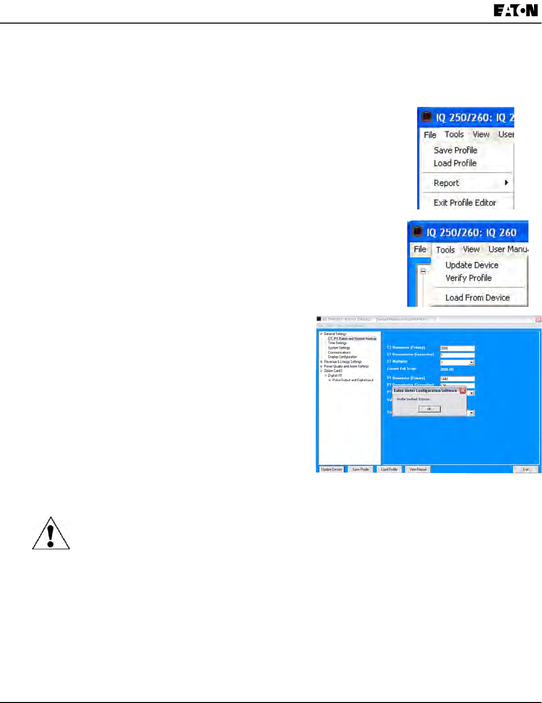
· Click File from the Title Bar to see the menu shown on the right.
The File menu allows you to perform functions that can also be performed
using the screen Buttons, described on the previous page: Save Prole,
Load Prole, Report, and Exit Prole Editor.
· Click Tools from the Title Bar to see the menu shown on the right.
The Tools menu allows you to:
o Update Device: Functions the same as the Update Device button.
See previous page for instructions and Note.
o Verify Prole: Click to perform a verication of the
current Device Prole settings. You will see a
window like the one shown below, on the right.
NOTE: If there are any errors, the number of errors
and type are listed in the window. Click View>Output
Logs>Errors to see more information about any
errors (refer to the View menu section on the next
page for additional information).
o Load from Device: Click to load the Settings elds
with values from the currently connected meter.
IMPORTANT! If you have made changes to the settings and have not saved them to a le or
updated the device, the changes are lost.
Chapter 8:
IQ 250/260 Meter Programming the IQ 250/260
www.eaton.com IB02601006E 8-5
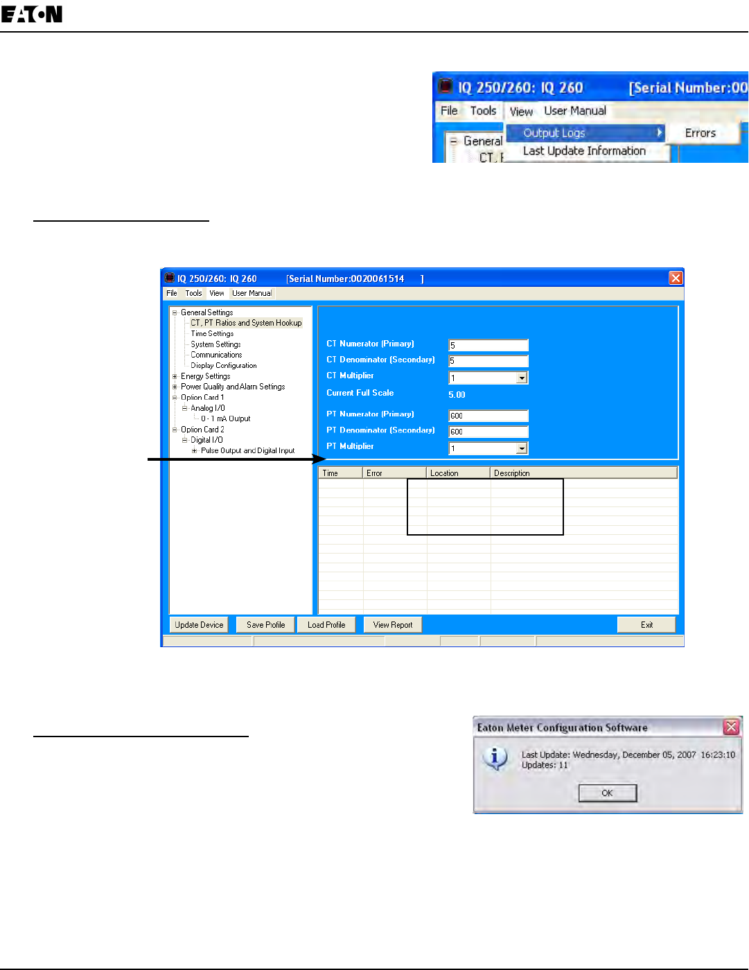
· Click View from the Title Bar to see the menu
shown on the right. The View menu allows you to:
o View Output Logs/Errors: View the Errors Log.
o View Last Update Information: View Update
information for this Device Prole.
NOTE: The instructions for these two functions follow.
Viewing Errors Output Log: Click Output Logs>Errors from the View menu to open a display on the bottom of the
screen, detailing any errors, the time they occurred, the location of the error, and a description of the error. See the
screen example below.
Click and Drag to
Resize Error
Display
You can resize the display by clicking and dragging on the line above the Errors display. Click View Output
Log>Errors a second time to remove the Errors display from the screen.
Viewing Last Update Information: click Last Update Information
from the View menu to open a window displaying the time and date
of the last update, and the total number of updates, for this
Device Prole.
Click OK to close the window.
Any Device Prole Errors
will be shown here

8-6 IB02601006E www.eaton.com
Chapter 8:
Programming the IQ 250/260 IQ 250/260 Meter
Conguring Settings
The following sections contain detailed instructions for conguring the Device Prole settings. All of the settings are
reached from the Tree Menu of the Device Prole screen.
Conguring CT, PT Ratios and System Hookup
Use this setting to congure Current Transformer and Potential Transformer ratios and to select the System
Hookup.
v Functional Overview of CT and PT Ratios:
Current and Potential Transformers are used mainly for the following reasons:
• To insulate, and as a result isolate, the meter from high-voltage circuits
• To change the primary voltage and current to standard values and sizes that the meter can measure.
The CT and PT transformers deliver fractions of the primary voltage and current to the meter. With properly set ratios
and multipliers, the readings of the meter can be used to determine the energy, voltage, current, or power of the
system.
From the Tree Menu, click General Settings>CT, PT, Ratios and System Hookup.
The screen elds and acceptable entries are as follows:
CT Ratios
CT Numerator (Primary): 1 - 9999
CT Denominator (Secondary): 5 or 1 Amp
NOTE: This eld is display only.
CT Multiplier (Scaling): 1, 10 or 100
Current Full Scale: Display only.
PT Ratios
PT Numerator (Primary): 1 - 9999
PT Denominator (Secondary): 40 - 600
PT Multiplier (Scaling): 1, 10, 100, or 1000
Voltage Full Scale: Display only.
System Wiring
3 Element Wye; 2.5 Element Wye; 2 CT Delta
Example Settings:
For a CT of 2000/5A, set the following CT Ratios in the entry elds:
CT Numerator (Primary) 2000
CT Denominator (Secondary) 5
CT Multiplier 1
The Current Full Scale eld will read 2000.
NOTE: You can obtain the same Current Full Scale by entering a CT Numerator of 200 and a CT Multiplier of 10.
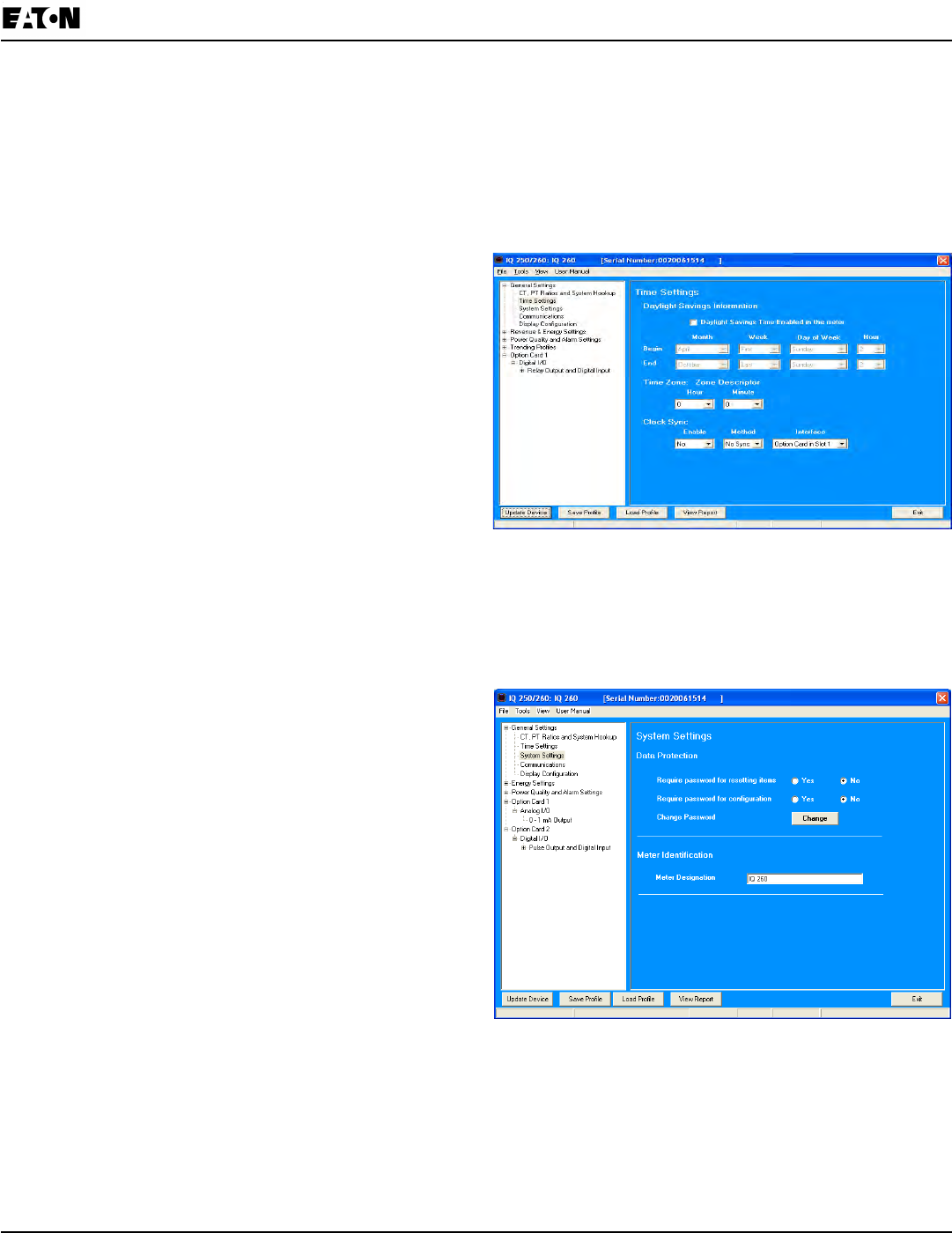
Chapter 8:
IQ 250/260 Meter Programming the IQ 250/260
www.eaton.com IB02601006E 8-7
For a system that has 14400V primary with a 120V secondary line to neutral (PT Ratio of 120:1), set the following
PT Ratios in the entry elds:
PT Numerator (Primary) 1440
PT Denominator (Secondary 120
PT Multiplier 10
The Voltage Full Scale eld will read 14400.
Conguring Time Settings
Use this setting to enable or disable Daylight Savings
Time for the IQ 250/260, and to set the beginning and
ending times for Daylight Savings Time. You can also set
the Time Zone and enable Clock Sync if supported by
your meter. From the Tree Menu, click General
Settings>Time Settings.
Check or uncheck the box to Enable or Disable
Daylight Savings time.
Use the entry elds to set the start and end times for
the Daylight Savings Time feature, if enabled. Select
the values you want from the Month, Week, Day of the
Week, and Hour elds.
Select the time Zone and Clock Sync options from the
pull-down menus,
NOTE: The Hour eld uses a 24-Hour clock.
Conguring System Settings
From the Tree Menu, click General Settings>System
Settings.
From this screen, you can do the following:
• Enable or Disable Password for Resetting
and/or Conguration: click the radio button next to
Yes or No.
Enabling Password protection prevents unauthorized
tampering with devices.
IMPORTANT! You must set up a password before
enabling Password Protection. Click the Change
button next to Change Password if you have not already
set up a password.
• Change the Password: click the Change button.
• Change the Device Designation: input a new designation into this eld.
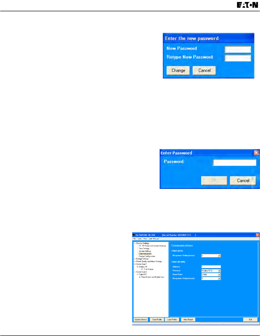
8-8 IB02601006E www.eaton.com
Chapter 8:
Programming the IQ 250/260 IQ 250/260 Meter
When you click the Change button next to Change Password in the Settings screen, you will see the Enter the
New Password screen.
1. Type in the new password (0 - 9999).
2. Retype the password.
3. Click Change. The new password will be saved and the meter
will restart.
NOTE: If Password Protection has already been enabled for conguration and you attempt to change the
password, you will see the Enter Password screen (shown below) after you click Change. Enter the old password
and click OK to proceed with the password change.
You can enable or disable a Password for Resetting (Reset Max/Min Energy Settings, Energy Accumulators, and
the Individual Logs) and Conguration (Device Prole) in the Systems Settings screen (see previous page).
NOTE: If you enable a Password for Resetting, you must also enable it for Conguration.
IMPORTANT! You must set up a password before enabling Password Protection. Click the Change button next
to Change Password if you have not already set up a password and follow the above instructions.
When anyone attempts to make a change that is under
Password protection, the Enter Password screen opens.
(See the example screen on the right.) If the correct Password is not
entered, the change will not take place.
Conguring Communications Settings
Use this screen to enter communication settings for the meter’s RS485 Port (Com 2).
NOTES:
• The settings on this screen are the current settings for communication.
• Any changes may affect communication between the meter and your PC.
From the Tree Menu, click
General Settings>Communications.
The screen elds and acceptable entries are as follows:
COM 2 (RS-485)
Address: 1 - 247
Protocol: Modbus RTU, Modbus ASCII or DNP 3.0

Chapter 8:
IQ 250/260 Meter Programming the IQ 250/260
www.eaton.com IB02601006E 8-9
NOTE: Response Delay is the delay the meter should use before responding to queries. If your connecting device
requires a delay before receiving information, use response delay to program the time to wait before the meter starts
responding to queries.
Setting Display Conguration
Use this screen to set the display of the meter’s faceplate. Refer to Chapter 6 of this manual for additional
information and instructions on using the faceplate.
From the Tree Menu, click General Settings>Display Conguration.
The screen elds and acceptable entries are as follows:
• Phases Displayed: A; A and B; A, B, and C. This
eld determines which phases display on the
faceplate. For example, if you select A and B, only
those two phases will be displayed on the faceplate.
• Auto Scroll Display: Yes or No. This eld enables or
disables the scrolling of selected readings on the
faceplate. If enabled, the readings scroll every
5 seconds.
• Enable on Face Plate of Display: Check the boxes of
the Readings you want displayed on the faceplate
of the meter. You must select at least one reading.
• Power Direction: View as Load or View as Generator
• Flip Power Factor Sign: Yes or No.
• Current Display Auto-Scale: On or Off (no decimal places)
• Load Bar Custom Conguration: Click this bar to add Current scaling. Additional elds open on the screen - see
the gure below.
Enter the Current scale you want to use, The Primary Full Scale eld will reect your entry (as it says on the
screen, Primary Full Scale Current for the Load Bar is equal to the Current Scale multiplied by the CT multiplier).

8-10 IB02601006E www.eaton.com
Chapter 8:
Programming the IQ 250/260 IQ 250/260 Meter
Conguring Energy, Power Scaling, and Averaging
Use this setting to congure:
• The display of Power in the meter
• The display and storage of Energy in the meter
• The interval over which Average values are computed.
v Functional Overview of Energy Settings and Averaging:
n Energy Scaling
Energy Setting includes:
• Digits (the number of digits in the reading)
• Decimals (the number of decimal places in the reading)
• Energy Scale: the scale of the reading – unit; kilo (number times 1000); Mega (number times 1 million).
Energy settings allow you to balance the resolution (or accuracy) of the energy stored, with the interval over which
energy rollover occurs. For example, the maximum resolution for a k scale reading is: 99999.999k.
To calculate the speed at which the energy will rollover, you must know the Energy Full Scale, which is computed
from the CT and PT Full Scale values (see Section 9.2.4.1). The formula for calculating Energy Full Scale is:
Wye system: CT Full Scale x PT Full Scale x 3
Delta system: CT Full Scale x PT Full Scale x 3 x √3
For example, for a CT Full Scale of 2000, PT Full Scale of 14400, Wye system:
2000 x 14400 x 3=86400000
In this example, the energy will increment at 86400000 Watts per hour, or 24000 Watts per second.
This value allows you to determine the number of digits, decimal places, and energy scale you want to congure for
the Energy settings, when you take into account the rollover time. To determine the number of hours before rollover,
use this formula:
[Max Resolution]/[Full Scale] = #Hours, where Max Resolution = maximum digits and decimals for the Energy scale
in use.
Using the example from above, with an energy scale of Mega, the formula would be:
99999.999 M/86.4 M = 1157.4074 hours or about 48 days until rollover.
NOTE: To increase the number of days until rollover, you can:
• Increase the number of digits (to 8)
• Decrease the number of decimal places (to 0)
• Increase the Energy Scale (to M).
n Demand Averaging
Demand is the average rate of energy use over time. The IQ 250/260 supports two types of demand averaging:
Fixed demand and Sliding demand:
• Fixed demand records the average demand for time intervals that you dene (usually 5, 15 or 30 minutes).
• Sliding demand functions like multiple, overlapping Fixed demand. You dene the subintervals at which an
average of demand is calculated. An example of Sliding demand would be a 15-minute Demand block using
5-minute subintervals, thus providing a new demand reading every 5 minutes, based on the last 15 minutes.
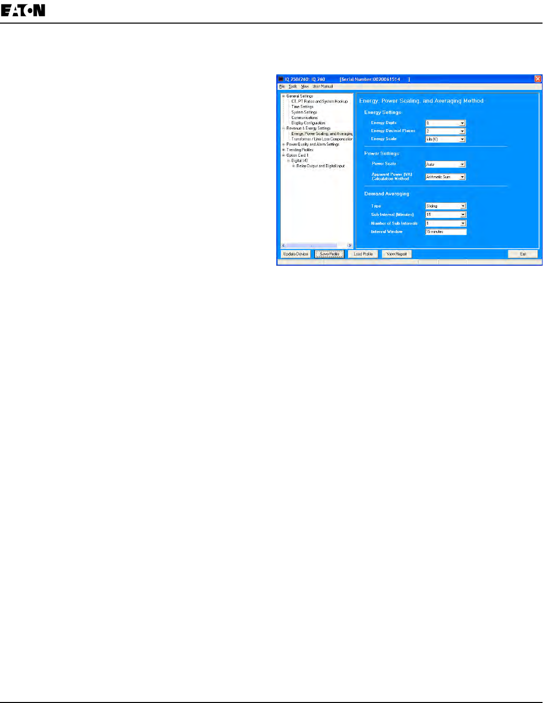
Chapter 8:
IQ 250/260 Meter Programming the IQ 250/260
www.eaton.com IB02601006E 8-11
From the Tree Menu, click Energy Settings> Energy, Power Scaling, and Averaging.
The screen elds and acceptable entries are as follows:
• Energy Settings
Energy Digits: 5; 6; 7; 8
Energy Decimal Places: 0 - 6
Energy Scale: unit; kilo (K); Mega (M)
For example: a reading for Digits: 8; Decimals: 3;
Scale: K would be formatted: 00123.456k
NOTES:
v Your selection in the Energy Settings elds
determines the precision of energy stored for
display and polling. Refer to the Functional
Overview at the beginning of this section for more
information.
v If you are changing the energy settings, we
recommend you rst reset the Energy Accumulators,
in order to prevent erroneous counts. See instructions
for resetting the meter’s Energy Accumulators, later in
this chapter.
• Power Settings:
Power Scale: Auto; unit; kilo (K); Mega (M)
Apparent Power (VA) Calculation Method: Arithmetic Sum or Vector Sum
• Demand Averaging:
Type: Fixed or Sliding
Interval (Fixed demand) or Sub-Interval (Sliding demand) in minutes: 5; 15; 30; 60
Number of Subintervals: 1; 2; 3; 4
Interval Window: This eld is display only. It is the product of the values entered in the Sub-Interval and Number
of Subintervals elds.
NOTE: You will only see the Number of Subintervals and Interval Window elds if you select Sliding Demand.
NOTE: If you have set an Input to trigger End of Interval (EOI) demand averaging (using either a Relay Output/
Digital Input or a Pulse Output/Digital Input Option card) any entry you make in the Demand Averaging eld will be
ignored. A message to that effect appears on the screen. See the Relay Card and Pulse Output Card instructions
later in this chapter.
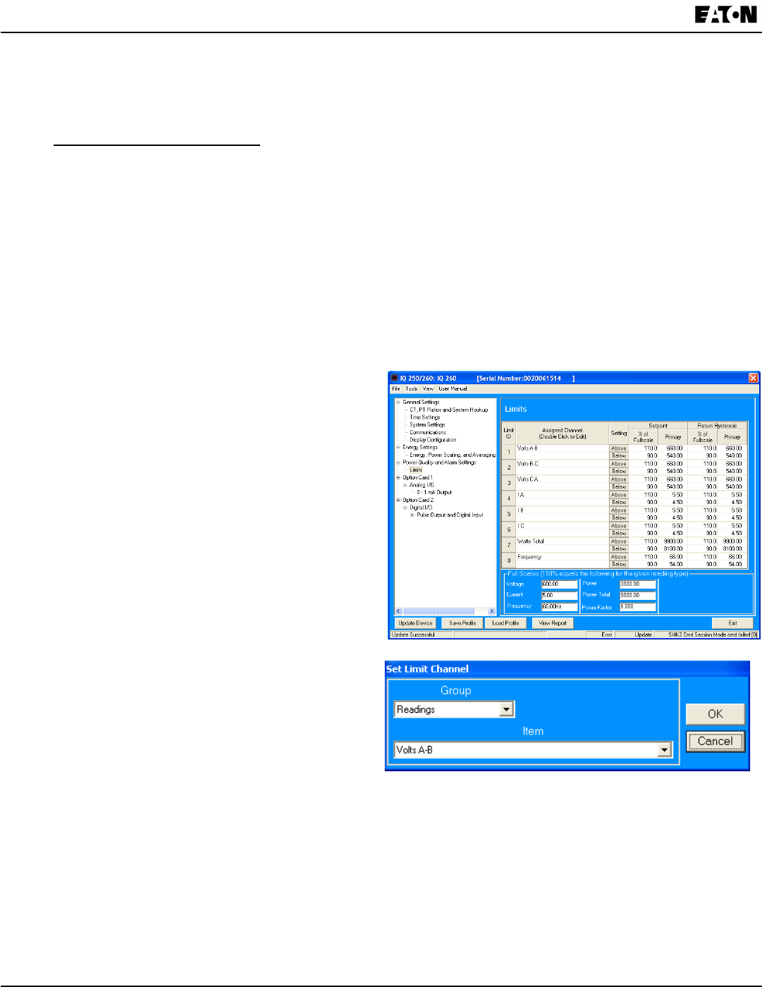
8-12 IB02601006E www.eaton.com
Chapter 8:
Programming the IQ 250/260 IQ 250/260 Meter
Conguring Limits (IQ 260 Only)
Use this screen to assign Limits for the meter.
v Functional Overview for Limits:
Limits are transition points used to divide acceptable and unacceptable measurements. When a value goes
above or below the limit, an out-of-limit condition occurs. You can set and congure up to eight Limits for the
IQ 260 meter.
Once they are congured, you can view the out-of-Limits (or Alarm) conditions in the Limits Polling screen.
You can assign the eight limits to readings from three groups of parameters:
• Readings (Instantaneous Voltage; Instantaneous Current; Total and Per Phase Power and Power Factor;
Frequency; and Neutral Current)
• Demand (Current; Per Phase, Total Power and Power Factor)
• THD (For IQ 260, voltage and current)
From the Tree Menu, click Power Quality and Alarm Settings>Limits.
The current settings for Limits are shown in the
screen.
The bottom of the screen shows the Full Scale values
for:
• Voltage
• Current
• Frequency
• Power
• Power Total
• Power Factor
• THD
• Phase Angles
1. Select a limit by double-clicking on the Assigned
Channel eld.
2. You will see the screen on the right. Select a Group
and an Item for the Limit.
3. Click OK.
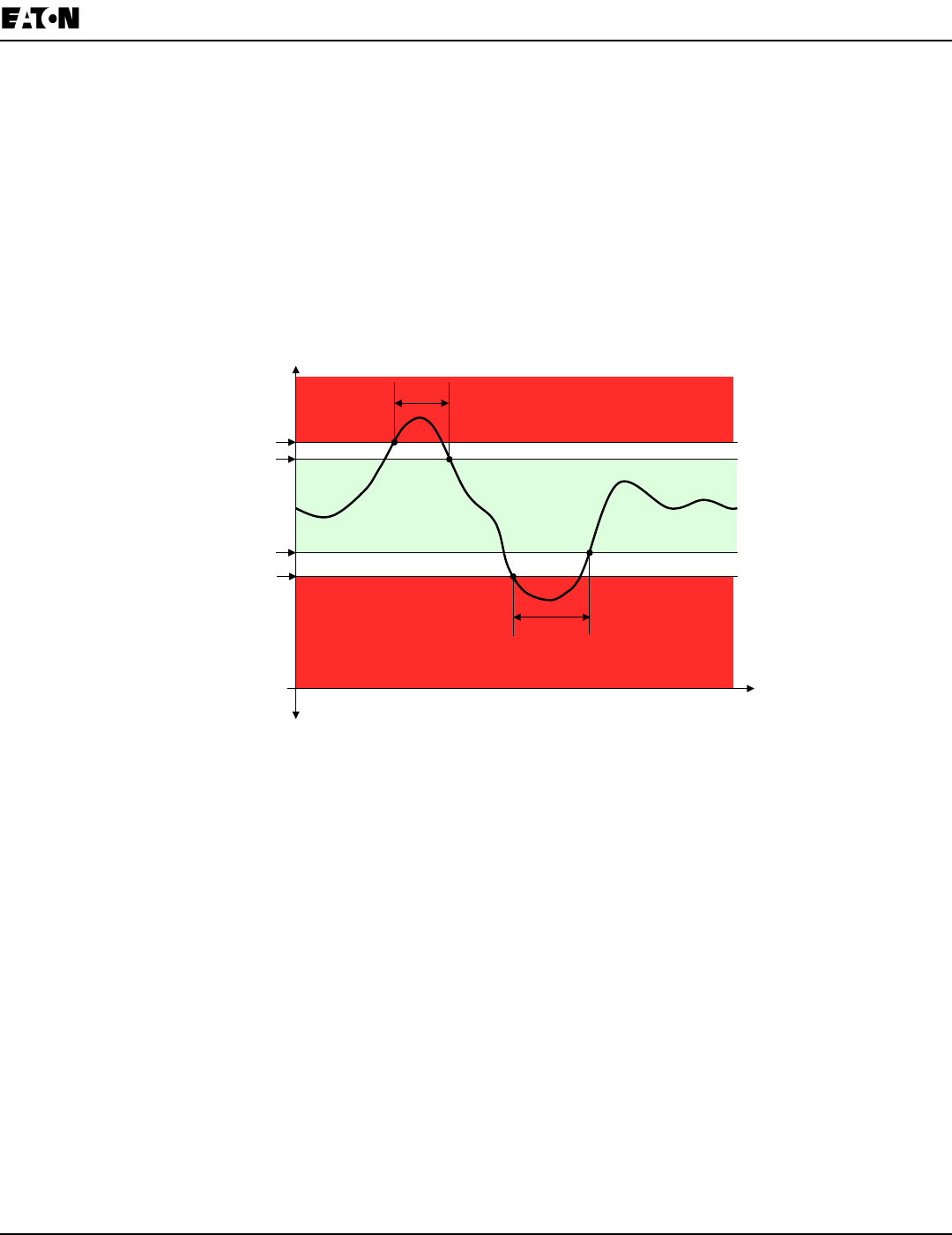
Chapter 8:
IQ 250/260 Meter Programming the IQ 250/260
www.eaton.com IB02601006E 8-13
To Congure a Limit:
Double-click on the Field to set the following values:
Above and Below Set Point: % of Full Scale (the point at which the reading goes out of limit)
Examples: 100% of 120V Full Scale = 120V
90% of 120V Full Scale = 108V
Above and Below Return Hysteresis: (the point at which the reading goes back within limit)
Examples: Above Set Point = 110% Below Set Point = 90%
(Out of Limit above 132V) (Out of Limit below 108V)
Above Return Hysteresis = 105% Below Return Hysteresis = 95%
(Stay Out of Limit until below 126V) (Stay Out of Limit until above 114V)
The Primary elds are display only. They show what the set point and return hysteresis value are for each limit.
NOTES:
• If you are entering negative limits, be aware that the negative value affects the way the above and below limits
function, since negative numbers are processed as signed values.
• If the Above Return Hysteresis is greater than the Above Set Point, the Above Limit is Disabled; if the Below
Return Hysteresis is less than the Below Set Point, the Below Limit is Disabled. You may want to use this feature
to disable either Above or Below Limit conditions for a reading.
TIME
Above Limit
condition
Below Limit
condition
Above Limit Trigger point
Return point from Above Limit condition
Below Limit Trigger point
Return point from Below Limit condition
HYSTERESIS
HYSTERESIS
- MEASURED VALUE
(if applicable)
+ MEASURED VALUE
0
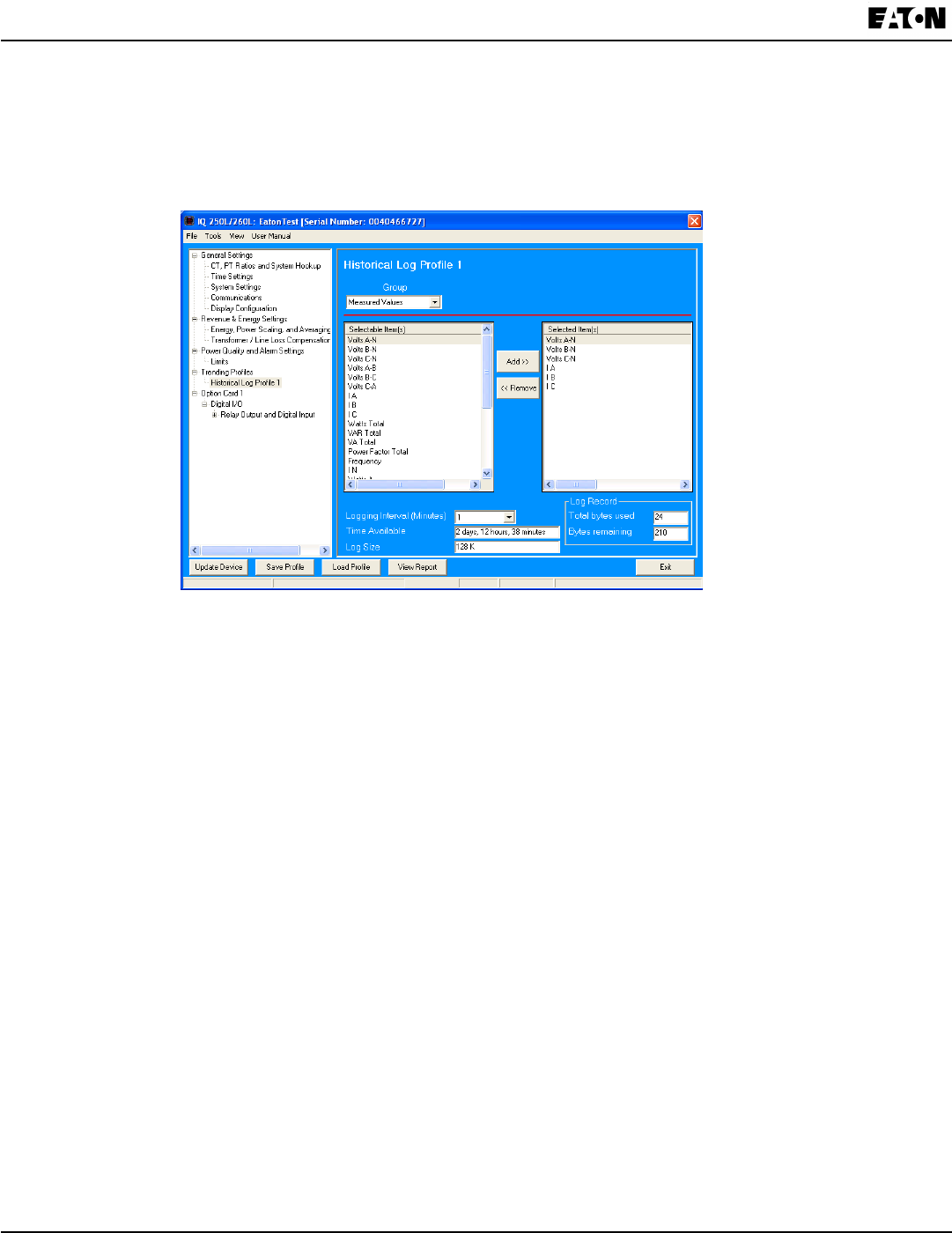
8-14 IB02601006E www.eaton.com
Chapter 8:
Programming the IQ 250/260 IQ 250/260 Meter
Conguring Trending Prole (Data logging option)
If your meter has the data logging option (see Chapter 2) you will see the Trending Proles setting in the Tree Menu.
Click on Trending Proles>Historical Log Prole 1 to display the screen shown below. (The screen shown here is
for an IQ 260 meter with the L option. If you are connected to an IQ250 with the L option, you won’t see the Power
Quality and Alarm menu options.)
This screen lets you select the data values for the Historical log. Depending on your meter model, Historical log
parameters can be selected from up to eleven groups:
Measured Values (Instantaneous Voltage; Instantaneous Current; Total and Per Phase Power and Power Factor; •
Frequency; Neutral Current; Symmetrical Components and Voltage Unbalances)
Demand (Current; Per Phase, Total Power and Power Factor)•
Maximums (Maximum values for all of the readings listed above, including THD (IQ 260 only), Voltage and •
currents)
Minimums (Minimum values for all of the readings listed above, including THD (IQ 260 only), Voltage and •
currents)
Energy (Watt-hours, VA-hours, VAR-hours)•
Accumulators (Input and Output Accumulator values)•
Short Term Min (Min value within the Demand Interval)•
Short Term Max (Max value within the Demand Interval)•
Uncompensated ((Watt-hours, VA-hours, VAR-hours)•
THD (For voltage and current) - IQ 260 with the L option only•
Harmonic Magnitudes (For voltage and current up to the 40th order) - IQ 260 with the L option only•
1. Select a Group.
NOTE: If you select Harmonic Magnitudes, another eld opens on the screen allowing you to select one of the
following for Harmonic Magnitude: Volts A; Volts B; Volts C; I A; I B; I C.
2. Select items for your log. The Group eld determines the items that are available for selection.
a. Highlight the item(s) you want in the Selectable Items box.
b. Click Add. The item(s) are added to the Selected Items box.
c. To remove item(s), highlight them in the Selected Items box and click Remove.
3. Set the Logging Interval (Minutes). The available choices are: 1, 3, 5, 10, 15, 30, 60, EOI (End of Interval) Pulse.
The Logging Interval determines when the meter takes a snapshot.
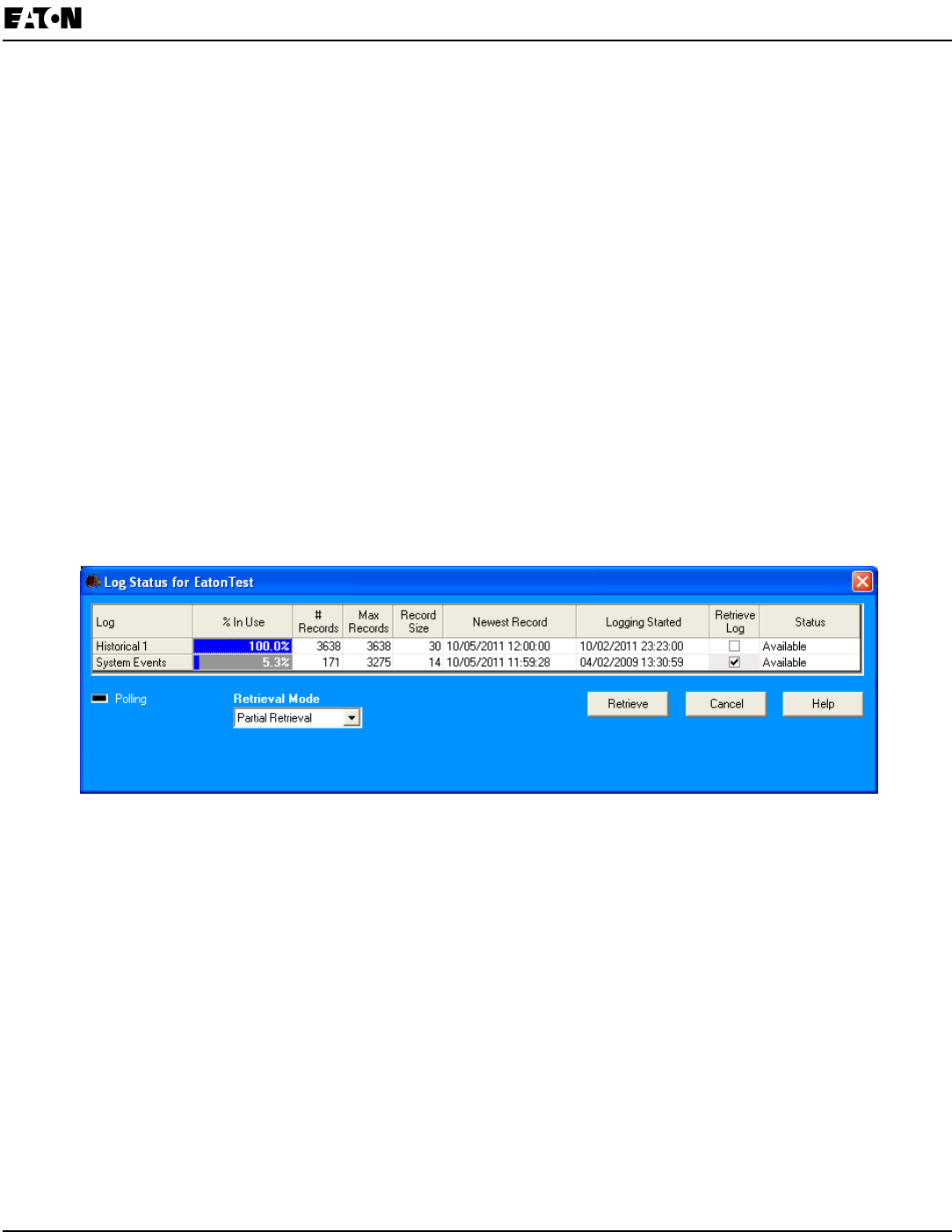
Chapter 8:
IQ 250/260 Meter Programming the IQ 250/260
www.eaton.com IB02601006E 8-15
NOTES:
Only one Option Card input or output can be set to trigger an EOI pulse.•
The maximum rate for EOI Pulse used to trigger a log is once per minute.•
When you choose EOI Pulse, the meter takes a snapshot on the End of Interval Pulse condition, rather than on •
a time interval. Below are two examples of using EOI Pulse for log recording.
Examples of EOI Pulse Recording:
A Relay Option Card is installed in your meter and set to trigger on a state change. You can use EOI pulse to •
take a snapshot upon that state change.
An IQ 260 meter is connected on each side of a load. You want to take a snapshot of both sides of the load at •
the same time. You can do this by connecting a Relay card in each of the meters to a device that will trigger
them. Then set the EOI pulse to take a snapshot when the devices are triggered.
NOTE: There are two display elds at the bottom of the Historical Log Prole screen. They show the Total Bytes
Used and the Bytes Remaining for this historical log. These elds are updated as you make selections on the
screen.
Viewing Log Status/Retrieving Logs (Data logging option, Option L)
For an IQ 250/IQ 260 meter, follow these steps to view Log status and/or retrieve logs.
1. Click Logs>Statistics or Logs>Retrieve Log(s) from Device from the Title bar (or click the Log Status or
Retrieve Logs icons). You will see the screen shown below.
2. This screen shows the following information for the Historical log (Historical 1) and the System Events log:
% in Use - the amount of the log that is currently being used•
# of Records - the number of records currently in the log•
Max Records - the maximum number of records the log can hold•
Record Size - the current record size in Bytes•
Newest Record - the date and time stamp of the most recent record in the log•
Logging Started - the date and time that logging began•
Retrieve Log - a checkbox that lets you select log retrieval•
Status - whether the log is Available or Not Available for retrieval•
3. To retrieve the Historical log, click its Retrieve Log checkbox.
NOTE: The System Events log is always retrieved when the Historical log is retrieved: its box is always checked.
4. Use the pull-down menu for Retrieval Mode to select one of two options:
Partial Retrieval (this is the default Retrieval mode)•
Time Range Retrieval •
NOTES:
In Partial Retrieval mode, only the newest records are retrieved. This increases retrieval speed, since records
that have previously been retrieved are ignored. When the log is full, it will roll over. Partial Retrieval mode
should be used for Billing and continuous logging.
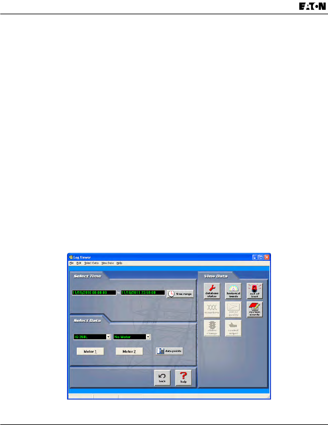
8-16 IB02601006E www.eaton.com
Chapter 8:
Programming the IQ 250/260 IQ 250/260 Meter
The Time Range Retrieval mode is useful if you want to retrieve specic events. If you select Use Time Range
from the pull-down menu, date range elds will display, allowing you to select the time range for data retrieval.
Only records (within the specied time range) that are newer than the latest records in the log database can be
retrieved for any selected logs. For this reason, Time Range Retrieval should not be used for Billing or
continuous logging purposes. The only way to retrieve earlier records using Time Range Retrieval is to delete the
existing log database(s) before retrieving the log(s).
5. Click Retrieve.
a. You will see a screen that shows the percent retrieved for each log, the time elapsed since retrieval
began, and any messages.
b. After the logs have been retrieved, you will see a screen which shows you the Mode, Start time, and Status of
Log Conversion.
c. The Log Viewer opens.
NOTES:
Only one person at a time can download a log. If someone else is downloading a log, it will be unavailable •
until the download is complete.
Retrieve logs as often as you want. Each time you retrieve a log le, Eaton Meter Conguration Software •
appends only the newest records and captures to the existing database.
Using the Log Viewer
To access Log Viewer, either:
Retrieve logs from a connected meter, as shown in the previous section.•
Click the Open Log icon from the Eaton Meter Conguration Software’s Main screen. The Retrieved Logs •
directory opens, allowing you to pick a previously stored log le.
Run Log Viewer from the Windows® Start menu.•
You will see the Log Viewer’s main screen, shown below.

Chapter 8:
IQ 250/260 Meter Programming the IQ 250/260
www.eaton.com IB02601006E 8-17
1. Choose the log data le(s) you want to view in either of the following ways:
If you have retrieved logs through Eaton Meter Conguration Software, the meter’s designated label is shown in •
the eld above the Meter 1 button. Click the Log’s button on the right side of the screen to view a log. (The but-
tons of unavailable logs are grayed out and unselectable.)
If you want to view a previously retrieved log, click either Meter button (1 or 2). Log Viewer opens a window •
prompting you to select a log database (.db). See the example screen below.
2. Select the le you want and click Open.
NOTE: You can choose a different log le (.db) for Meter 1 and for Meter 2.
3. Select the data points you want to view by clicking the Data Points button in Log Viewer’s Main screen. You will
see the screen shown below. Note that the number of data points you see reects the number of parameters
in the log.
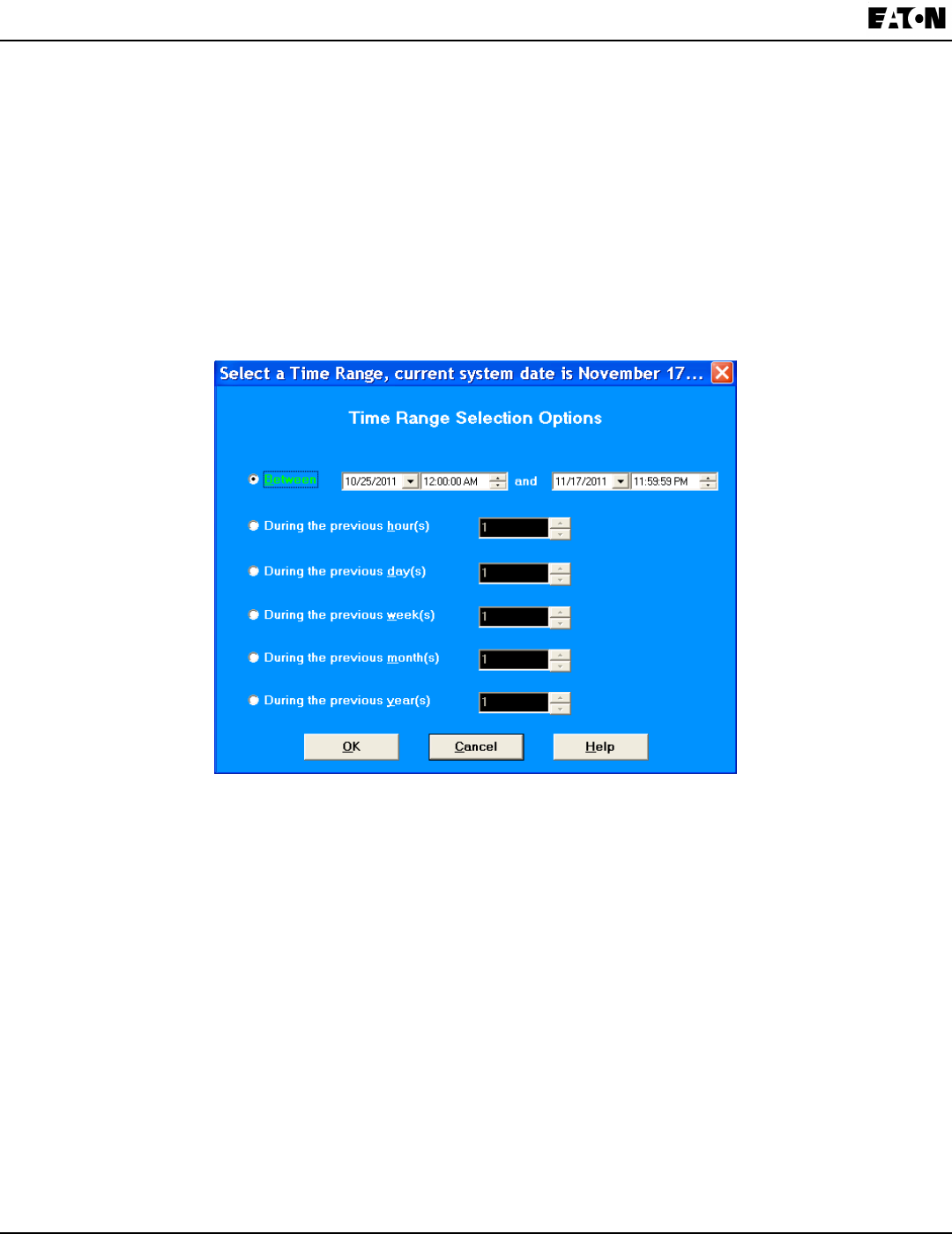
8-18 IB02601006E www.eaton.com
Chapter 8:
Programming the IQ 250/260 IQ 250/260 Meter
4. From the Available Data Points column, click on the data points you want to include when viewing the log le. To
select multiple points, hold down the Ctrl key while clicking. To select points in sequence, hold down the Shift
key while clicking.
Click the Add button to move the Data Points to the Selected Data Points column.•
Click the Restore button to return the selection to its previous setting.•
5. When you nish your selection, click OK to return to Log Viewer’s main screen.
6. Select the portion of the log you want to view by specifying a time range. Log Viewer bases its time/date format on
your computer’s Regional Settings (Windows® Control Panel). Click the Time Range button. You will see the
following screen:
To select a specic time range, click the Between radio button and enter a date and time in each eld. You can •
also the arrows to open a calendar for the date and to increment the time eld.
To select a range of hours, days, months or years only, click the appropriate radio button and use the arrows to •
select the range.
7. Click OK. The time range you selected is displayed in the Log Viewer’s main screen.
8. Click on the Historical Trends button or View Data>Snapshots. Log Viewer displays trending data for the selected
log le based on the time range and data points you chose. See the example screen on the next page.

Chapter 8:
IQ 250/260 Meter Programming the IQ 250/260
www.eaton.com IB02601006E 8-19
The name of the log le and the type of data point are listed in the top row.•
You can move the columns, so that the most important data is most accessible. Right-click on the column title •
and drag it to the desired location on the table.
To save the data to your clipboard, right-click with the cursor positioned anywhere in the table.•
To sort the data by Date/Time or data point, in either ascending or descending order, click the Sort button and •
use the pull-down menus to make your selection. See the screen shown below.
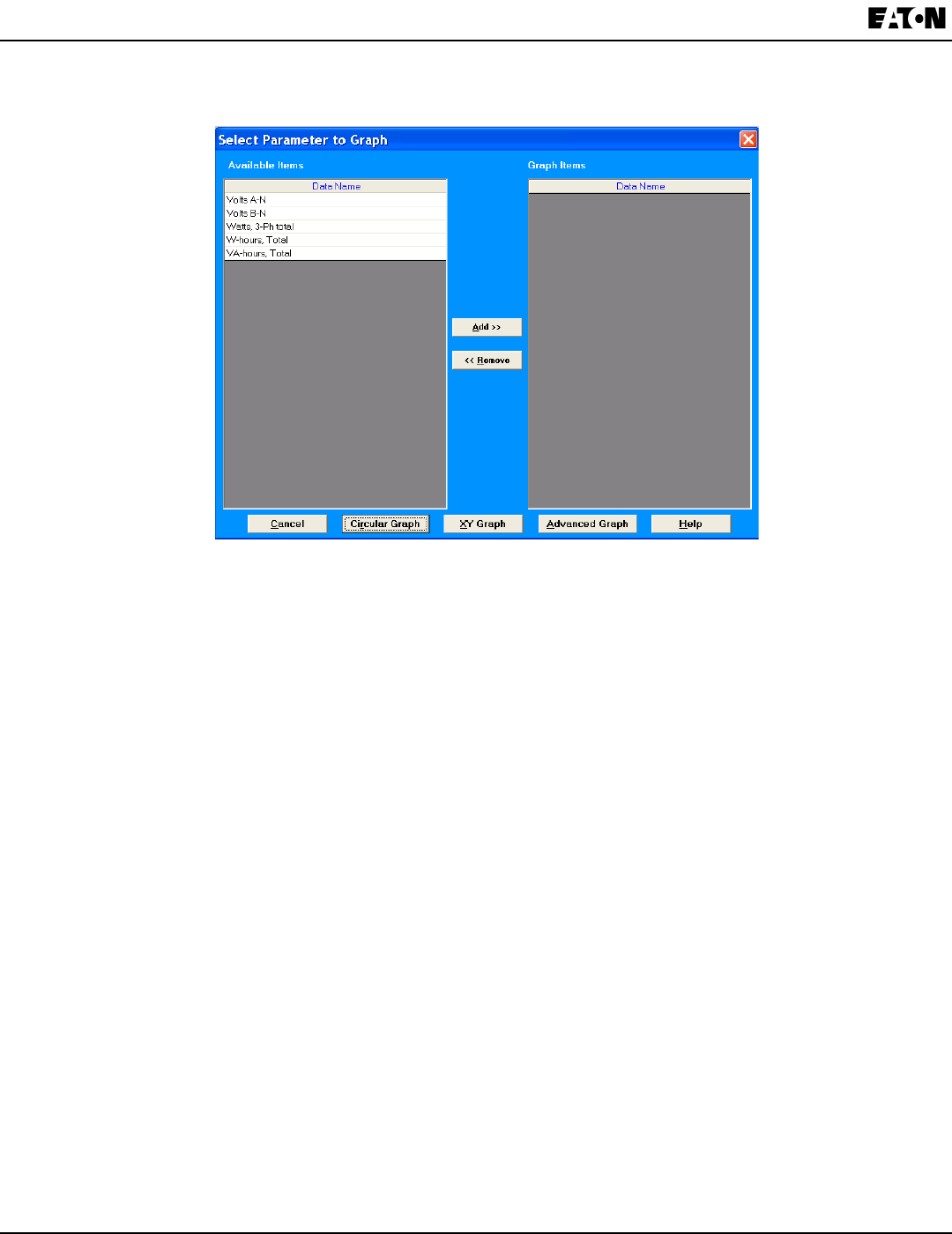
8-20 IB02601006E www.eaton.com
Chapter 8:
Programming the IQ 250/260 IQ 250/260 Meter
9. To display Trending data as either an XY, Circular, or Advanced graph, click the Graph button. You will see the
following screen.
The Available Items column lists the log’s data points. (To add a new data point, return to Log Viewer’s main
screen and click the Data Points button.)
a. Click on the data points you want to graph.
b. Click the Add button. The items appear in the Graph Items column. To select multiple data points, hold
down the Ctrl key while clicking. To select data points in sequence, hold down the Shift key while clicking.
NOTE: Only six data points in total can be graphed at one time. If there are two open log les, you can only
select three data points per le.
c. To view the graph, click either the Circular, XY, or Advanced Graph buttons. See the example graphs
on the next two pages.
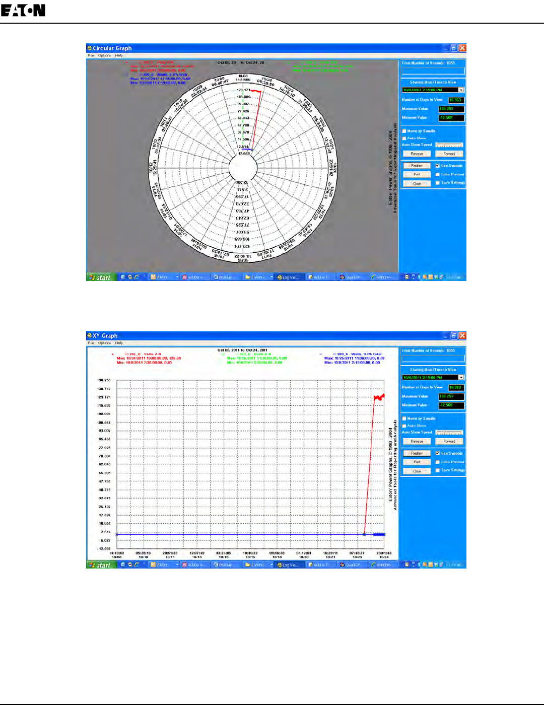
Chapter 8:
IQ 250/260 Meter Programming the IQ 250/260
www.eaton.com IB02601006E 8-21
Circular Graph
XY Graph

8-22 IB02601006E www.eaton.com
Chapter 8:
Programming the IQ 250/260 IQ 250/260 Meter
Advanced Graph
The following instructions pertain to all of the graphs:
To change the starting point of the graph, choose a new date/time segment from the Starting Date/Time to View •
pull-down menu.
To change the amount of time represented on the graph, enter a value in the Number of Days to View eld and •
press Enter or click on the Redraw button.
To change the scale of the graph, enter a value in the Minimum Value and Maximum Value elds and press •
Enter or the Redraw button.
To view one sample at a time, click in the Move by Sample box; then click on the Forward or Reverse buttons •
each time you would like to view the next (or previous) sample.
To view a continuous, sample-by-sample rendering of the graph, click the Move by Sample box and the Auto •
Show box. Select a speed by sliding the Auto Show Speed bar left or right; click on the Forward or Reverse but-
tons to determine the direction of the Auto Show. To stop Auto Show, deselect the Auto Show box.
To print the graph on a color printer, check the Color Printout box and click Print.•
To print the graph on a black-and-white printer, click the Use Symbols box and click Print.•
To copy the graph data to the computer’s clipboard, select Copy from the File menu. Paste the data into aspread •
sheet, such as Excel®.
To export the graph’s data, select Export Data from the File menu.•
To change the graph’s color assignments, select Select Colors from the Options menu. You will see the screen •
shown on the next page.
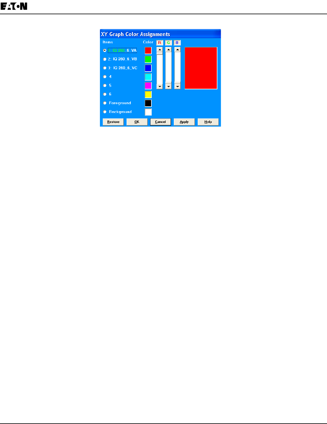
Chapter 8:
IQ 250/260 Meter Programming the IQ 250/260
www.eaton.com IB02601006E 8-23
NOTES:
- The Advanced Graph also has a Color button which opens the Color Assignments screen.
- The Color Assignments screen is slightly different for the Advanced Graph.
The small squares under the Color heading represent the color currently assigned to each component of
the graph. To make adjustments to an Item’s color, click the radio button beside it and create a new color
by moving the red, green and blue sliders. Create black by moving all sliders down, white by moving all
sliders up. The large square on the right shows the color you have created.
Click OK to return to the graph; Log Viewer redraws the graph using the new color scheme. Click the
Restore button to return all color schemes to their default values.
10. When you are nished using the Log Viewer, click the X button or File>Exit to close the screen.
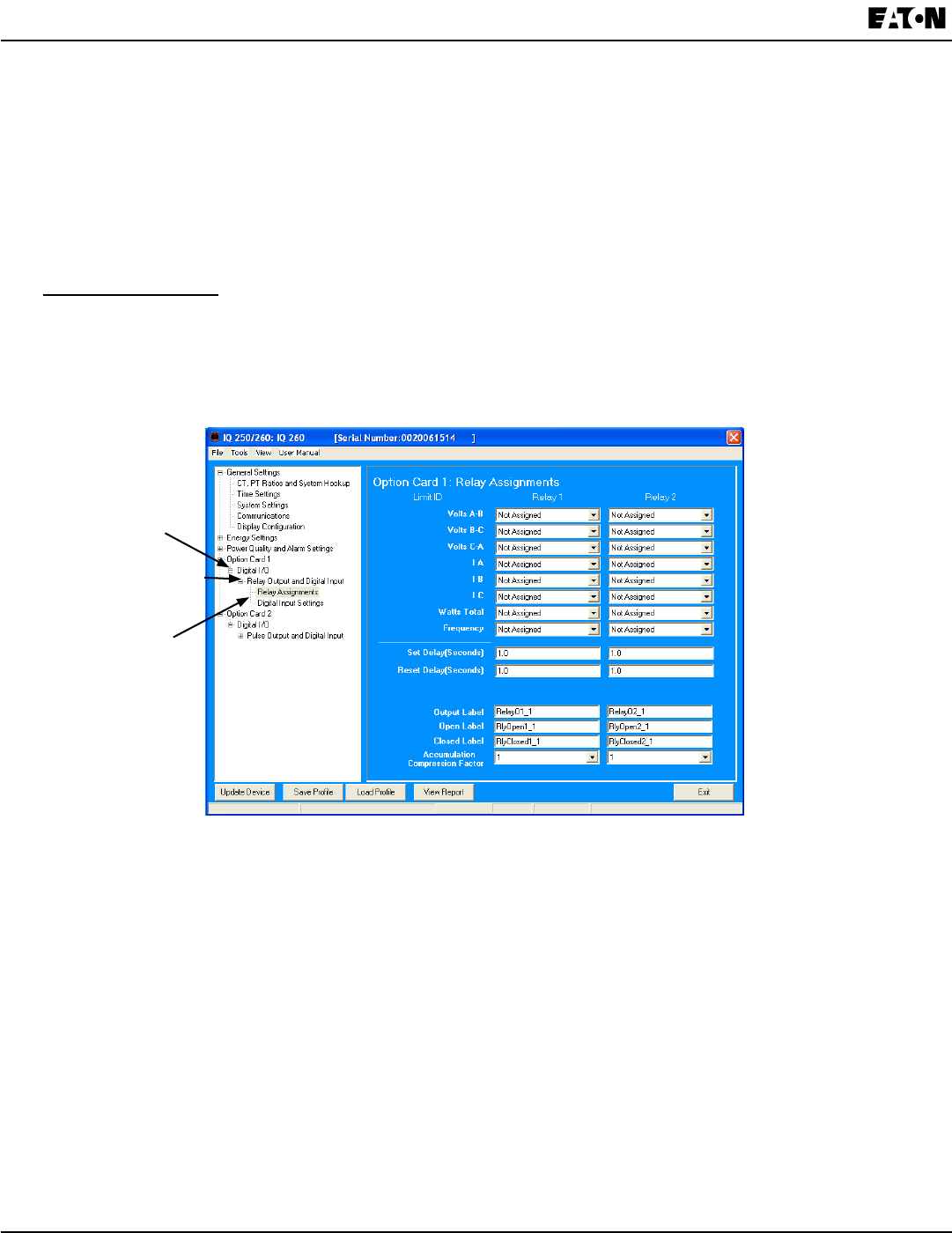
8-24 IB02601006E www.eaton.com
Chapter 8:
Programming the IQ 250/260 IQ 250/260 Meter
Conguring I/O Option Cards
The IQ 250/260 Meter automatically detects the presence of any Option cards installed in it. You will see the
installed card(s) listed in the Tree Menu (see gure below). Up to two Option cards can be installed in the
meter. Refer to Chapter 7 of this manual for additional information concerning Option cards, including installation
procedures.
You must congure an Option card before using it. The following sections provide you with instructions for
conguring each of the available Option cards.
Option Card Screens:
The type of Option card installed in the meter determines the settings you need to congure, and so, the screens
you will see. Click on the selectable lines under your Option card in the Tree menu. See the example below.
General Type of Card
e.g., Digital I/O
Card Name,
e.g. Relay Output and
Digital Input
Option Card
Settings screens, e.g.,
Relay Assignments,
Digital Input Settings
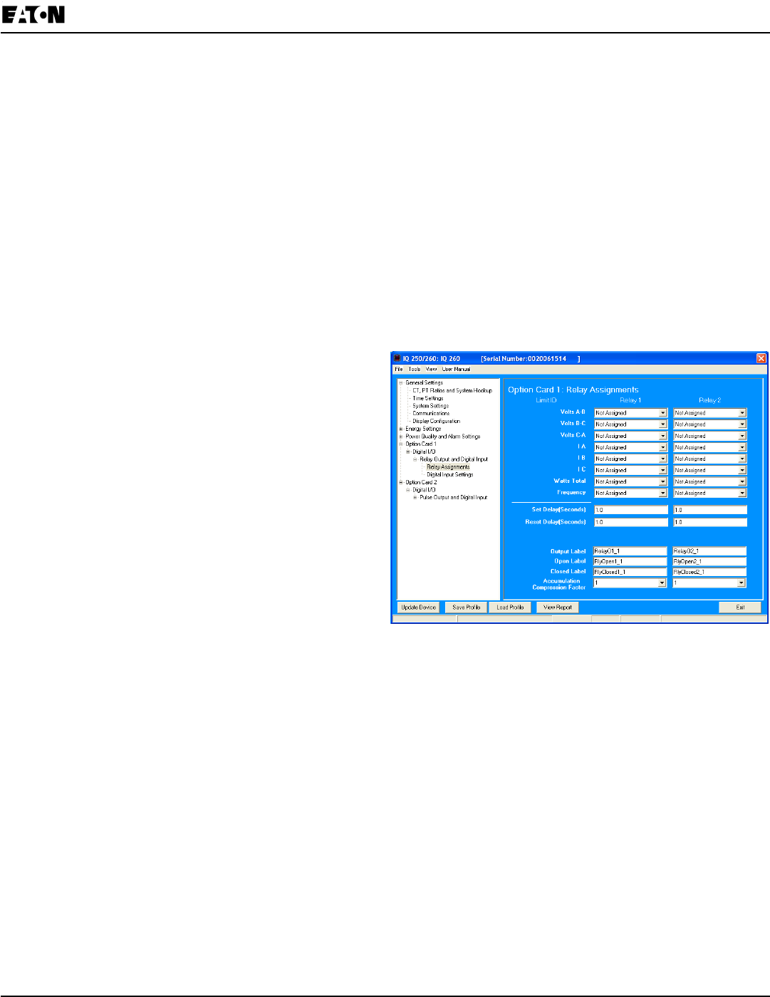
Chapter 8:
IQ 250/260 Meter Programming the IQ 250/260
www.eaton.com IB02601006E 8-25
Conguring a Relay Output/Digital Input Card (IQ250/260-IO1):
The Relay Output/Digital Input Option Card has:
· Two relay contact outputs for load switching
· Two wet/dry contact sensing digital inputs.
Accumulators in the software count the transitions of the Inputs and Outputs.
For technical specications and hardware installation, refer to Chapter 7 of this manual.
NOTE: When installing a Relay Output/Digital Input card, we recommend you reset the accumulators for the card,
in order to prevent erroneous counts. See instructions on using the Reset Device Information screen to reset card
accumulators, later in this chapter.
An example use of the optional Relay Card is in monitoring the status of circuit breakers or relays in your electrical
system. The two status inputs could be used to monitor two circuit breakers, and the two relay outputs could be used
to sound an alarm upon the occurrence of a programmed out of limit condition (IQ 260, only). Relay outputs on IQ
250/260 can be manually triggered: see the “Performing Manual Relay Control” section, later in this chapter.
Click Relay Assignments to set the limits/alarm conditions (IQ 260, only) and labeling and compression op-
tions for the card’s Relay Outputs. From the Relay Assignments screen, you can:
• Congure up to 8 limits for each of the two Relay
Outputs (IQ 260)
• Set a Delay and Reset Delay for the Outputs (IQ 260)
• Assign each Output an Output Label, Open Label,
and Closed Label
• Assign an Accumulation Compression Factor for
each output
IMPORTANT! First use the Limits screen to set up the
limits you want to assign to an Output. See
instructions earlier in this chapter.
NOTE: The Limits functionality is only available for
the IQ 260. If you are connected to an IQ 250, you
will only see the Label and Accumulation
Compression Factor elds in this screen.
1. The available Limits appear in the Limit ID column.
To assign a Limit to an Output Relay:
Select the Alarm trigger from the pull-down menu next to the Limit ID. The options are:
• Above Limit (the Output is triggered when the Above Limit condition occurs)
• Below Limit (the Output is triggered when the Below Limit condition occurs).
You can assign the limit to one or both (or neither) of the Relay Outputs.
NOTE: A Relay operates when any one assigned Limit is tripped, and stays in the Set condition as long as one
Limit is in the Alarm state.
2. You can enter Set Delay and/or Reset Delay. These values are the delay before the Output is changed: Set is
when the common is shorted to Normal Open (this is the Set Condition).
3. The current Output Labels are displayed in the screen. These labels are used for Logging. To change the
Output labels, click in the Labels eld you want to change, and enter a new label. The elds that can be changed
are:
• Output Label – Label ID
• Open Label – Open state ID
• Closed Label – Closed state ID
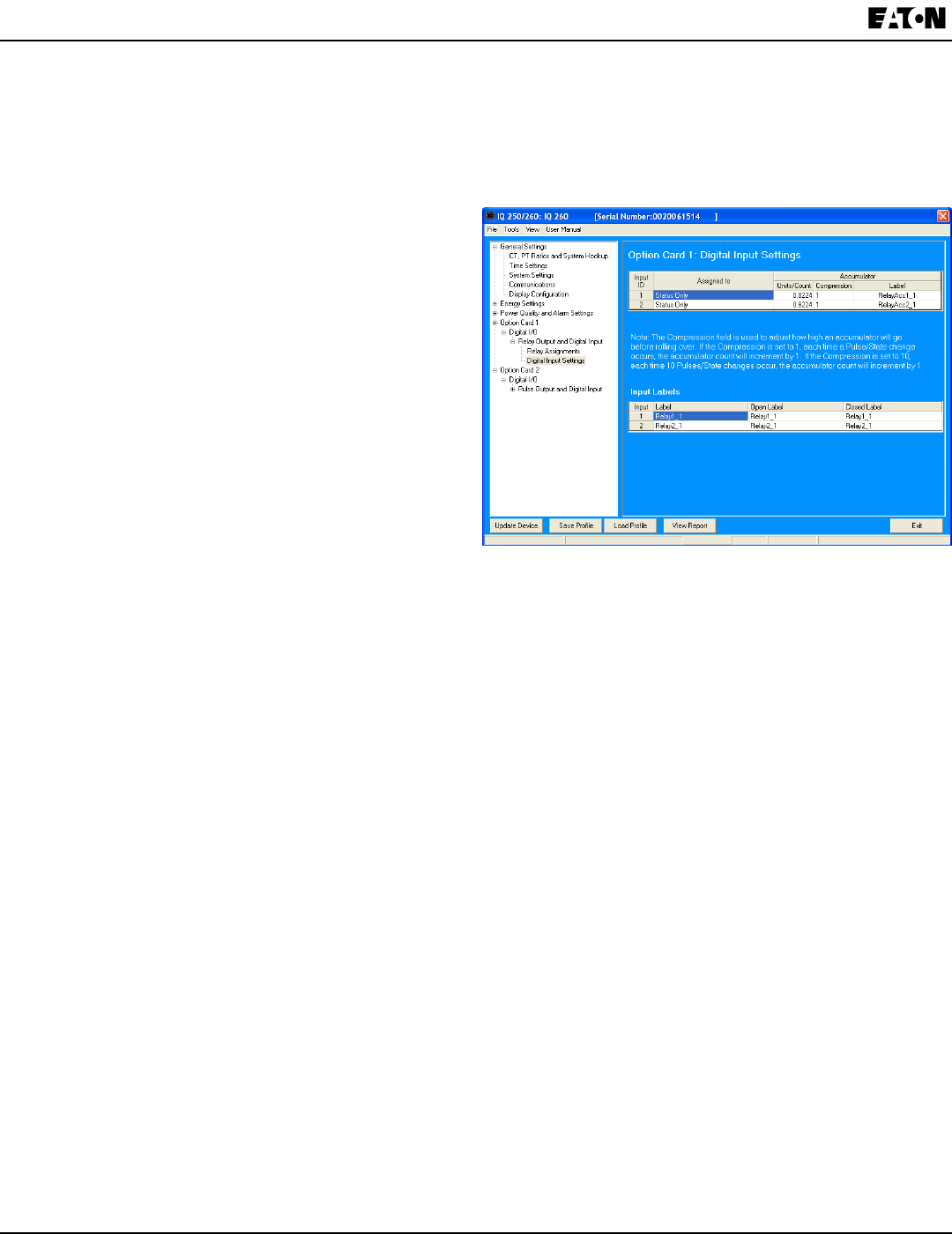
8-26 IB02601006E www.eaton.com
Chapter 8:
Programming the IQ 250/260 IQ 250/260 Meter
4. You can specify an Accumulation Compression Factor. The Compression Factor is used to adjust how high an
accumulator will go before rolling over. Because of this, it is useful in delaying rollover.
For example, if you select a Compression Factor of 10, each time 10 Pulse/State changes occur, the accumulator
count will increment by 1. The available Compression Factors are: 1, 10, 100, 1000, 10000, and 100000. The
default Compression Factor is 1.
5. To congure the Relay Inputs, click Digital Input Settings. Use this screen to set up Accumulators and Input
Labels.
• You can set up to two Input IDs for your Relay
Card, and assign a Label, Open Label, and
Closed Label for each.
• You can assign labels and other information for
Accumulators for the Inputs.
a. Make a selection in the Assigned to eld.
The available selections are:
• Status Only
• EOI Pulse, Trigger on Contact Closing
• EOI Pulse, Trigger on Contact Opening
• EOI Pulse, Trigger on Contact Change
• Accumulator, Increment on Contact
Closing
• Accumulator, Increment on Contact Opening
• Accumulator, Increment on Contact Change
NOTES on End of Interval (EOI):
• EOI is triggered when the selected condition is met.
• EOI is used as a trigger for demand averaging: when the selected condition is met, the EOI delineates
an interval that results in demand averaging being performed.
• The minimum interval between EOI Pulses used to trigger demand averaging should be 5 minutes.
• Only one Option Card input or output can be set to trigger an EOI pulse.
b. Enter Units/Count. The Units/Count is the output ratio from the device that is being input into the meter.
For example, if you have a KYZ module that is outputting a pulse every 1.8 kWh, with the input set to
Accumulator, Increment on Contact Opening, you would set the Units/Count to be the value of the KYZ; in
this case either 1.8 or a ratio of that number.
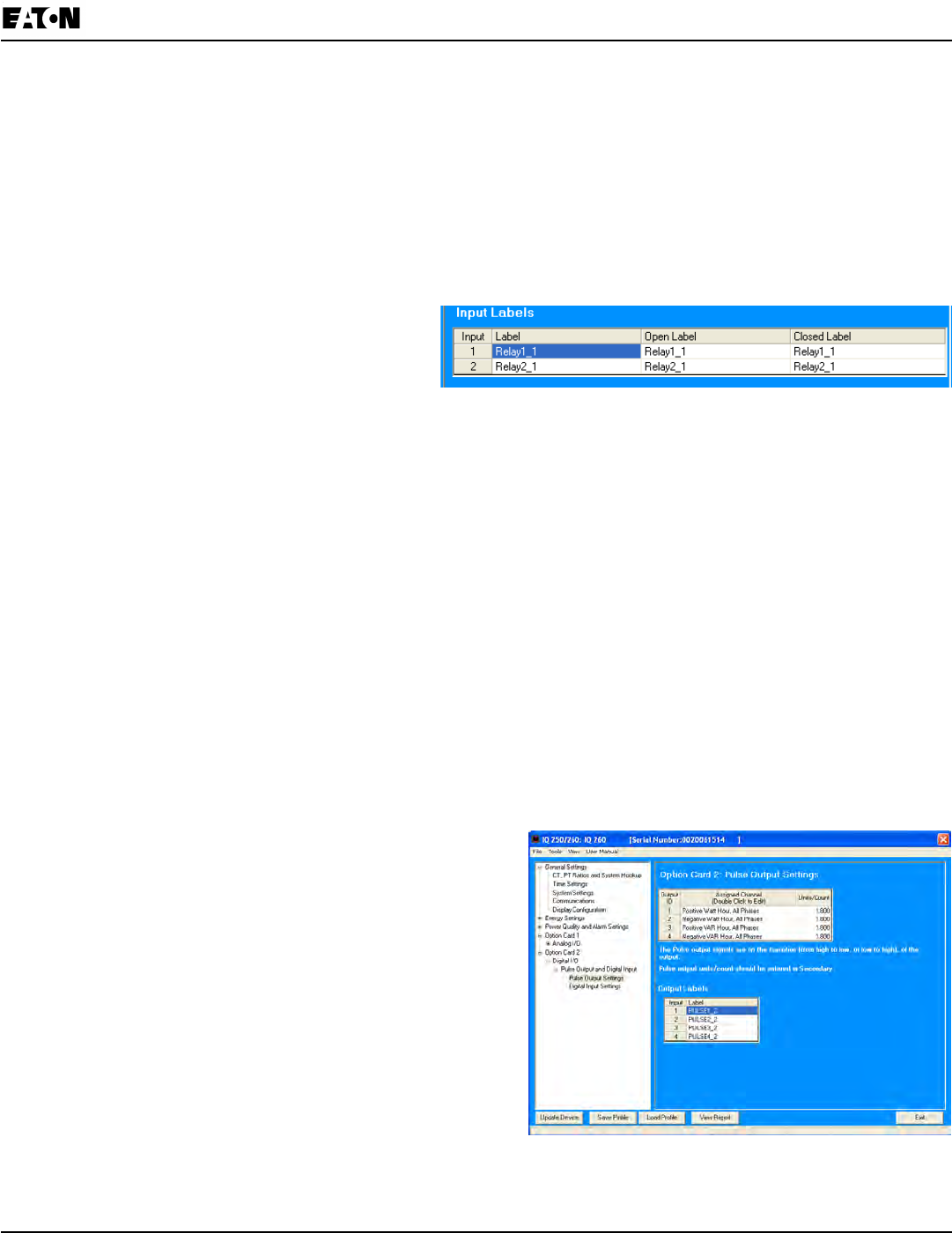
Chapter 8:
IQ 250/260 Meter Programming the IQ 250/260
www.eaton.com IB02601006E 8-27
c. Enter Compression. The Compression Factor is used to adjust how high an accumulator will go before
rolling over. For example, if you select a Compression Factor of 10, each time 10 Pulse/State changes
occur, the accumulator count will increment by 1.
The available Compression Factors are: 1, 10, 100, 1000, 10000, and 100000. The default Compression
Factor is 1.
d. Enter a Label for the Accumulator.
e. The current Input Labels are displayed in the screen. To change the Input Labels, click in the Labels eld
you want to change, and enter a new label. The elds that can be changed are:
• Input Label – Input ID
• Open Label – Open state ID
• Closed Label – Closed state ID
Conguring a Pulse Output/Digital Input Card (IQ250/260-IO2):
The Pulse Output/Digital Input Option Card has:
• Four Pulse Outputs via solid state contacts
• Four wet/dry contact sensing digital inputs.
Accumulators in the software count the pulses of the Inputs and Outputs. For technical specications and hardware
installation, refer to Chapter 7 of this manual.
NOTE: When installing a Pulse Output/Digital Input card, we recommend you reset the accumulators for the
card, in order to prevent erroneous counts. See instructions on using the Reset Device Information screen to reset
card accumulators, later in this chapter.
An example use of the Pulse Output/Digital Input Card is in a sub-metering application where a pulse output is
needed. The Input Accumulators allow you to count the pulses from another device, for example, a KYZ module or
another meter. The Output Accumulators allow you to count the pulses being output by the card.
The Pulse Output and Digital Input Card has two screens for conguration: the Pulse Output Settings screen
and the Digital Input Settings screen.
1. Click Pulse Output Settings.
• You can set up to four Output IDs for your Card.
• Each Output has a Label, an Assigned Channel, and a
Unit/Count.
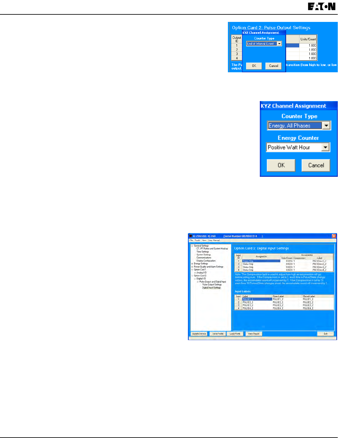
8-28 IB02601006E www.eaton.com
Chapter 8:
Programming the IQ 250/260 IQ 250/260 Meter
2. Double-click an Assigned Channel eld to add or edit an Output ID.
You will see the window shown on the right.
3. Select the Counter Type. The available selections are:
• Energy, All Phases
• End of Interval Event – this counter is triggered by a
Demand Averaging Interval
• Energy, Phase A
• Energy, Phase B
• Energy, Phase C
• None.
NOTE: If you select one of the Energy Counter Types, you will see the Energy
Counter eld, shown on the right. The available selections are: Total Watt Hour;
Positive Watt Hour; Negative Watt Hour; Total VAR Hour; Positive VAR Hour;
Negative VAR Hour; VA Hour; Received Watt Hour; Delivered Watt Hour;
Inductive VAR Hour; Capacitive VAR Hour.
4. Click OK. The Counter Type you selected displays in the Assigned Channel eld
of the Pulse Output Settings screen.
5. When you select the Assigned Channel, a value is entered for it in the Units/Count
eld. You can edit this eld by double-clicking in it. The Units/Count is determined by the Secondary (the
readings in the meter).
6. The current Output Labels are displayed on the screen. To change the Output labels, click in the Labels eld
you want to change, and enter a new label.
7. Click Digital Input Settings.
• You can set up to four Input IDs for your Card, and
assign a Label, Open Label, and Closed Label for
each.
• You can assign labels and other information for
Accumulators for the Inputs.
a. Make a selection in the Assigned to eld. The
available selections are:
• Status Only
• EOI Pulse, Trigger on Contact Closing
• EOI Pulse, Trigger on Contact Opening
• EOI Pulse, Trigger on Contact Change
• Accumulator, Increment on Contact Closing
• Accumulator, Increment on Contact Opening
• Accumulator, Increment on Contact Change
NOTES on End of Interval (EOI):
• EOI is triggered when the selected condition is met.
• EOI is used as a trigger for demand averaging: when the selected condition is met, the EOI delineates
an interval that results in demand averaging being performed.
• The minimum interval between EOI Pulses used to trigger demand averaging should be 5 minutes.
• Only one Option Card input or output can be set to trigger an EOI pulse.
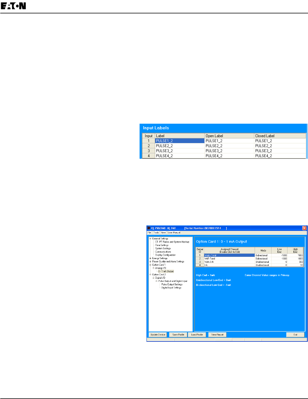
Chapter 8:
IQ 250/260 Meter Programming the IQ 250/260
www.eaton.com IB02601006E 8-29
b. Enter Units/Count. The Units/Count is the output ratio from the device that is being input into the
meter. For example, if you have a KYZ module that is outputting a pulse every 1.8 kWh, with the
input set to Accumulator, Increment on Contact Opening, you would set the Units/Count to be the value
of the KYZ; in this case either 1.8 or a ratio of that number.
NOTE: When EOI is chosen for the Assigned to, a pulse is generated on the selected EOI Event.
When this option is chosen, you do not need to set Units/Count.
c. Enter Compression. The Compression Factor is used to adjust how high an accumulator will go
before rolling over. Because of this, it is useful for delaying rollover. For example, if you select a
Compression Factor of 10, each time 10 Pulse/State changes occur, the accumulator count will
increment by 1. The available Compression Factors are: 1, 10, 100, 1000, 10000, and 100000. The
default Compression Factor is 1.
d. Enter a Label for the Accumulator.
· The current Input Labels are displayed on
the screen. To change the Input Labels,
click in the Labels eld you want to change,
and enter a new label.
Conguring a 0-1 mA Output Card (IQ250/260-IO3):
The 0-1mA Output Option Card is an analog communication card, which transmits a standard, bi-directional 0-1
milliamp signal. For technical specications and hardware installation, see Chapter 7 of this manual.
An example use of the optional 0-1mA Output Card is in enabling the meter to communicate with an RTU (Remote
Terminal Unit).
1. Click 0-1 mA Output.
· You can set up to four Output IDs for your
Output Card.
2. Double-click an Assigned Channel eld to add
or edit an Output ID. You will see the window
shown on the next page.
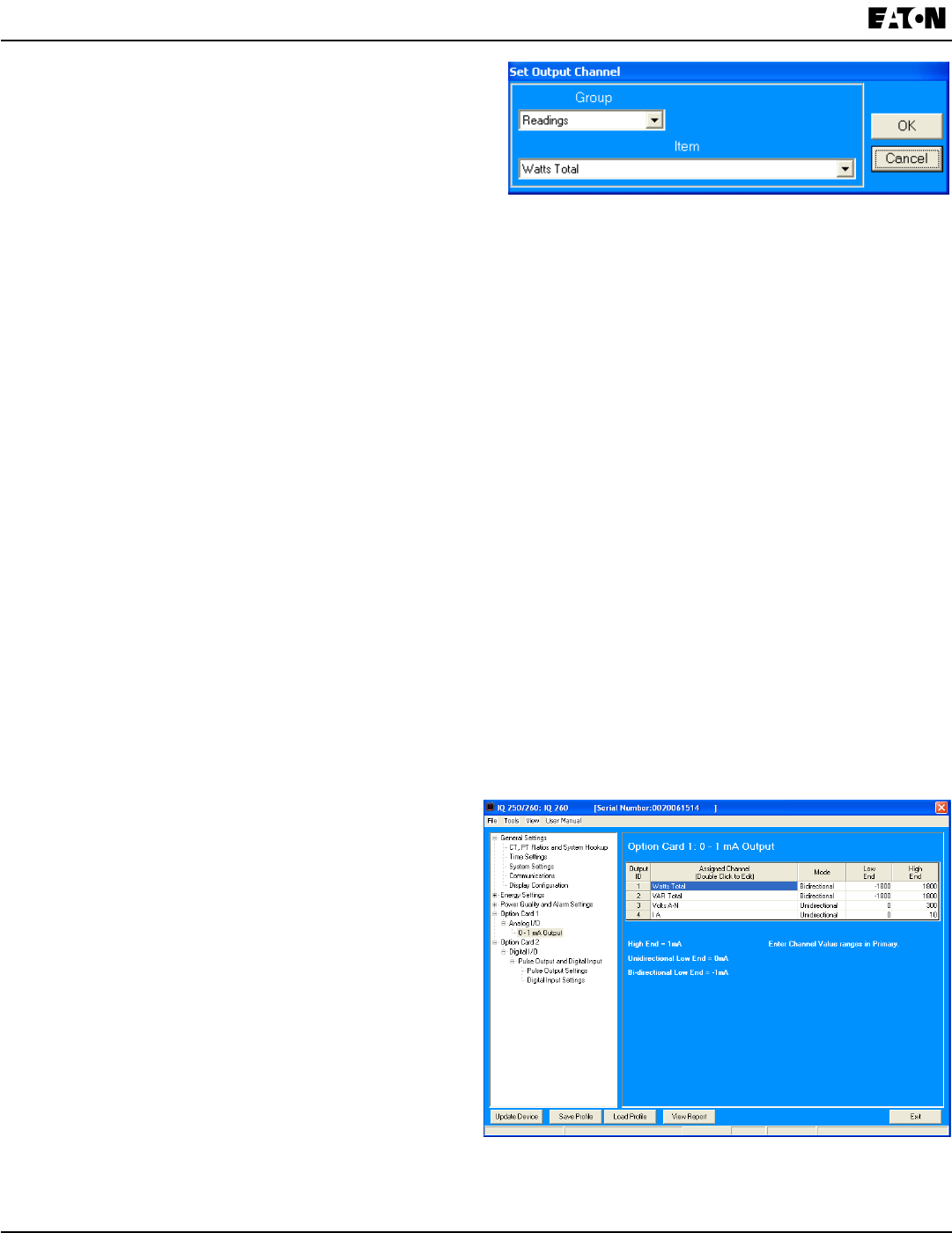
8-30 IB02601006E www.eaton.com
Chapter 8:
Programming the IQ 250/260 IQ 250/260 Meter
3. Select Group for your Output Channel. The available
selections are as follows:
• Readings
• Demand
• Maximums
• Minimums
• Phase Angles
• THD
• Not Assigned.
4. Select Item for your Output Channel. The items are the available readings for the group you selected. For
example, as shown in the window above, Volts A-N is an item you can select when you have selected Readings
as the Group.
5. Click OK. The Output Channel you selected is displayed in the Assigned Channel eld.
6. Enter Low End and High End for the channel.
NOTE: For the Item selected for the Assigned Channel, the Output Card takes the value in the meter and outputs a
DC current within its range. The Low End is the lowest value, and the High End is the highest value. For example,
for VOLTS A-N and Bidirectional Mode, at Full Scale of 120V, the Low End is 115V and the High End is 125V. The
Analog Output Card will output –1 mA when the reading is 115V, 0 mA when the reading is 120V, and 1 mA when the
reading is 125V.
7. You can select either Unidirectional or Bidirectional for Mode.
8. Enter an Update Rate. The suggested rate is between 100 and 200 msec.
Conguring a 4-20 mA Output Card (IQ250/260-IO4):
The 4-20mA Output Option Card is an analog communication card, which transmits a standard, uni-directional
4-20 milliamp signal.For technical specications and hardware installation, see Chapter 7 of this manual.
An example use of the optional 4-20mA Output Card is in enabling the meter to communicate with an RTU (Remote
Terminal Unit).
Click 4-20 mA Output.
Follow the instructions for conguring the
0-1 mA Card. The conguration of a 4-20 mA Card
is the same as a 0-1 mA Card, except that this card
can only be unidirectional.
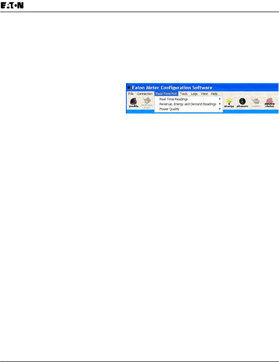
Chapter 8:
IQ 250/260 Meter Programming the IQ 250/260
www.eaton.com IB02601006E 8-31
Polling the IQ 250/260 Meter
n The Real Time Poll features of the Eaton Meter Conguration Software are used to continuously view
instantaneous values within an IQ 250/260 Meter. The software provides tabular views of metered values,
circuit measurements, interval data, Power Quality values, Pulse data and Input/Output status and
accumulations.
The Real Time Poll features are divided into three groups, accessed by clicking the Real Time Poll menu in the
Title Bar:
• Real Time Readings
• Revenue, Energy and Demand Readings
• Power Quality and Alarms
When you click Real Time Readings; Revenue, Energy and Demand Readings; and Power Quality and
Alarms, you will see a sub-menu that allows you to select individual polling screens.
n NOTE: Clicking the Polling Icon on the Title Bar is the same as selecting Instantaneous Polling from the Real-
Time Poll>Real Time Readings menu; clicking the Phasors Icon on the Title Bar is the same as selecting
Phasors from the Real-Time Poll>Power Quality and Alarms menu.
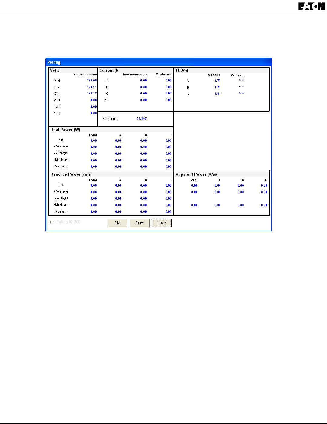
8-32 IB02601006E www.eaton.com
Chapter 8:
Programming the IQ 250/260 IQ 250/260 Meter
Instantaneous Polling
n Click Real-Time Poll>Real Time Readings>Instantaneous Polling. You will see the screen shown below.
NOTE: You will only see the THD Readings if you are connected to an IQ 260.
n Click Print to print a copy of the screen.
n Click Help to view instructions for this screen.
n Click OK to return to the main screen.
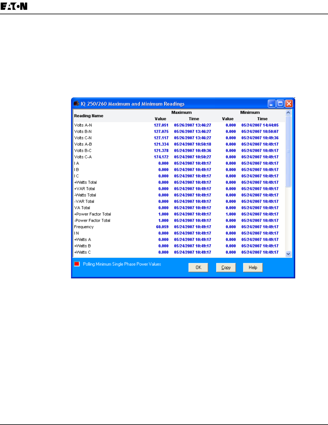
Chapter 8:
IQ 250/260 Meter Programming the IQ 250/260
www.eaton.com IB02601006E 8-33
Poll Max and Min Readings
Click Real-Time Poll>Real Time Readings>Poll Max and Min Readings. You will see the screen shown below.
This screen displays the maximum and minimum values and the time of their occurrence for all of the IQ 250/260
Real-Time readings. Use the scroll bar to view readings not displayed on the screen.
n Click Copy to copy the readings to the clipboard. You can then
paste them into another document, for example, an Excel le.
n Click OK to close the screen.
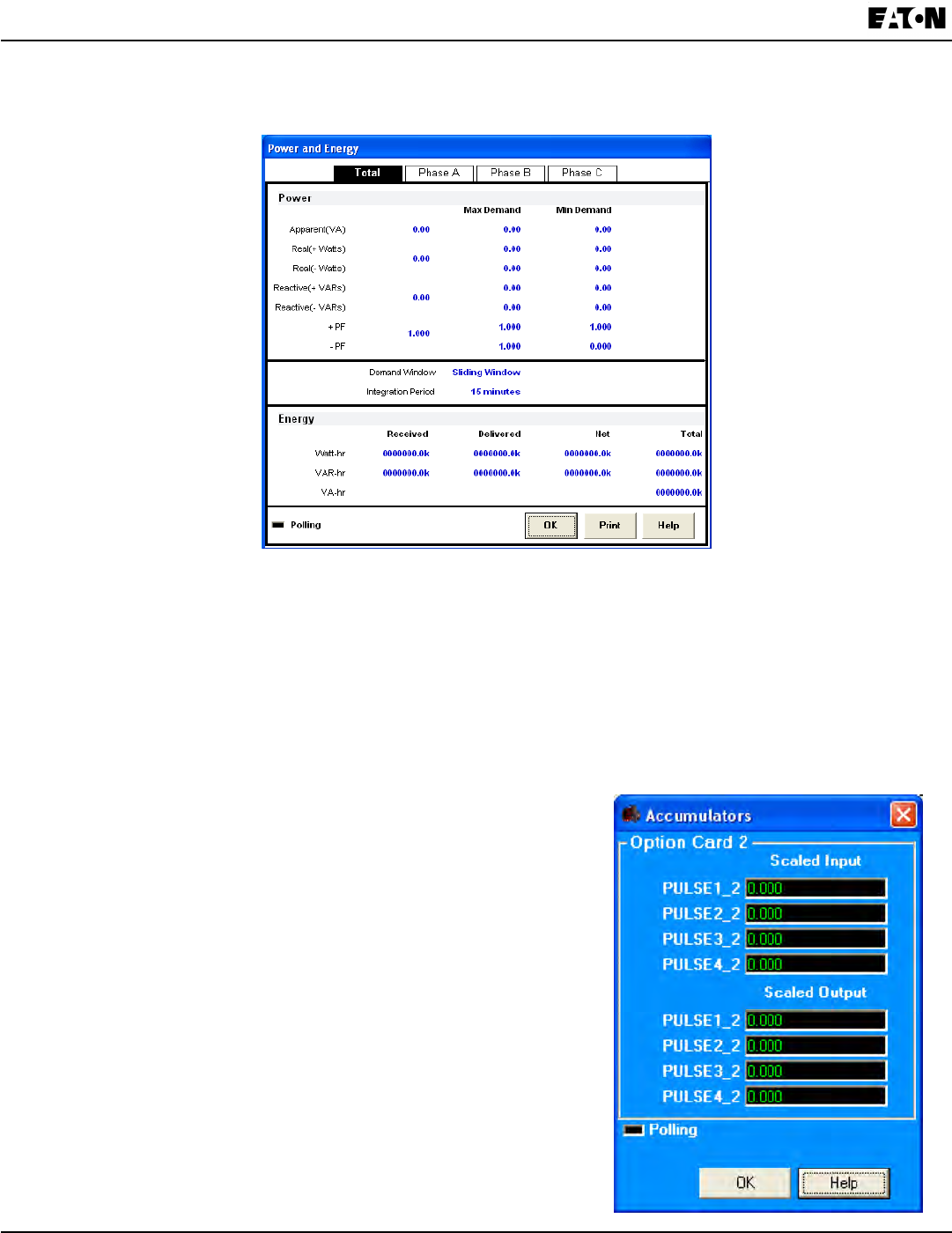
8-34 IB02601006E www.eaton.com
Chapter 8:
Programming the IQ 250/260 IQ 250/260 Meter
Poll Power and Energy
n Click Real-Time Poll>Revenue, Energy and Demand Readings>Power and Energy. You will see the screen
shown below.
This screen displays the power and energy for Total Power and all three phases.
1. Click the tabs at the top of the screen to select the view you want:
• Total
• Phase A
• Phase B
• Phase C
2. Click Print to print the readings.
3. Click OK to close the screen.
Poll Accumulators
n Click Real-Time Poll>Revenue, Energy and Demand Readings>
Accumulations. You will see the screen shown on the right.
This screen displays the current readings for the Input and
Output Accumulators of any installed Relay Ouput/Digital Input
and Pulse Output/Digital Input Option cards.
The readings are shown after the congured Compression and
Units/Count have been applied. For information on setting
Compression and Units/Counts for Accumulators, refer to
the instructions for conguring Relay Output/Digital Input
and Pulse Output/Digital Input Cards, earlier in this chapter.
Click OK to close the screen.
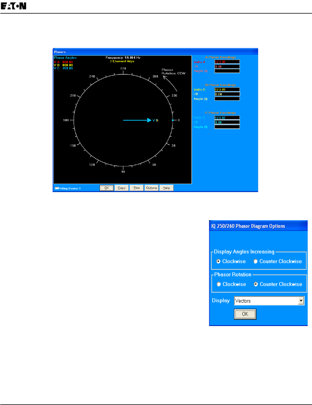
Chapter 8:
IQ 250/260 Meter Programming the IQ 250/260
www.eaton.com IB02601006E 8-35
Poll Phasors
1. Click Real Time Poll>Power Quality and Alarms>Phasors. You will see the screen shown below.
The Phasors screen displays the Phase relationships of the currently connected IQ 250/260. If you have an
auxiliary voltage reading (i.e. generator and bus where the V Aux is the generator), Aux box and the V Aux
phaser are displayed. The V Aux phasor is referenced to V A phase.
2. To adjust the Phasor display, click Options at the bottom of the screen.
You will see the screen shown on the right.
a. In the Display Angles Increasing and Phasor Rotation boxes,
select either Clockwise or Counter Clockwise.
b. From the pull-down menu at the bottom of the screen, select
Vectors, Triangles or Vectors and Triangles to change the graphic
representation of the data.
3 Click OK to save your selections and return to the Phasors screen.
• Click Copy to save a copy of the screen to the clipboard.
• Click Print to send a copy of the graph to a printer.
• Click Help to view instructions for this screen.
• Click OK to return to the main screen.
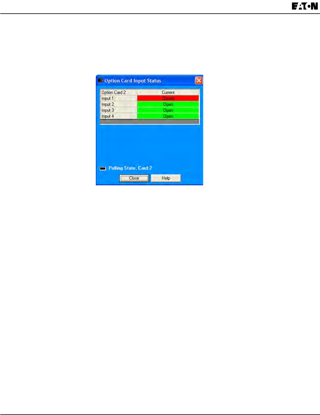
8-36 IB02601006E www.eaton.com
Chapter 8:
Programming the IQ 250/260 IQ 250/260 Meter
Poll Status Inputs
1. Click Real Time Poll>Power Quality and Alarms>Poll Status Inputs. You will see the screen shown below.
This screen displays the status (Open or Closed) of the Digital Inputs of any installed Relay Output/Digital Input
or Pulse Output/Digital Input Option cards.
2. Click Close to close the screen.

Chapter 8:
IQ 250/260 Meter Programming the IQ 250/260
www.eaton.com IB02601006E 8-37
Poll Limits (IQ 260 Only)
Click Real-Time Poll>Power Quality and Alarms>Limits. You will see the screen shown below.
This screen shows the current status of any Limits programmed in the Device Prole.
NOTE: See instructions for conguring Limits, earlier in this chapter.
1. The displayed elds are:
• Limit ID – the identication of the limit.
• Label - the item the Limit is set for.
• Value – the current reading for this item.
• Status/Limit1/Limit2 – whether the current reading is “In” or “Out” for the Above (Limit 1) and Below (Limit 2)
Setpoints.
• Limit 1/Setting/Point/Hysteresis – Above: the point above which the reading goes out of limit (Setpoint) and the
point at which it returns to within limit (Hysteresis).
• Limit 2/Setting/Point/Hysteresis – Below: the point below which the reading goes out of limit (Setpoint) and the
point at which it returns to within limit (Hysteresis).
2. Click Print to print the screen.
3. Click OK to close the screen.
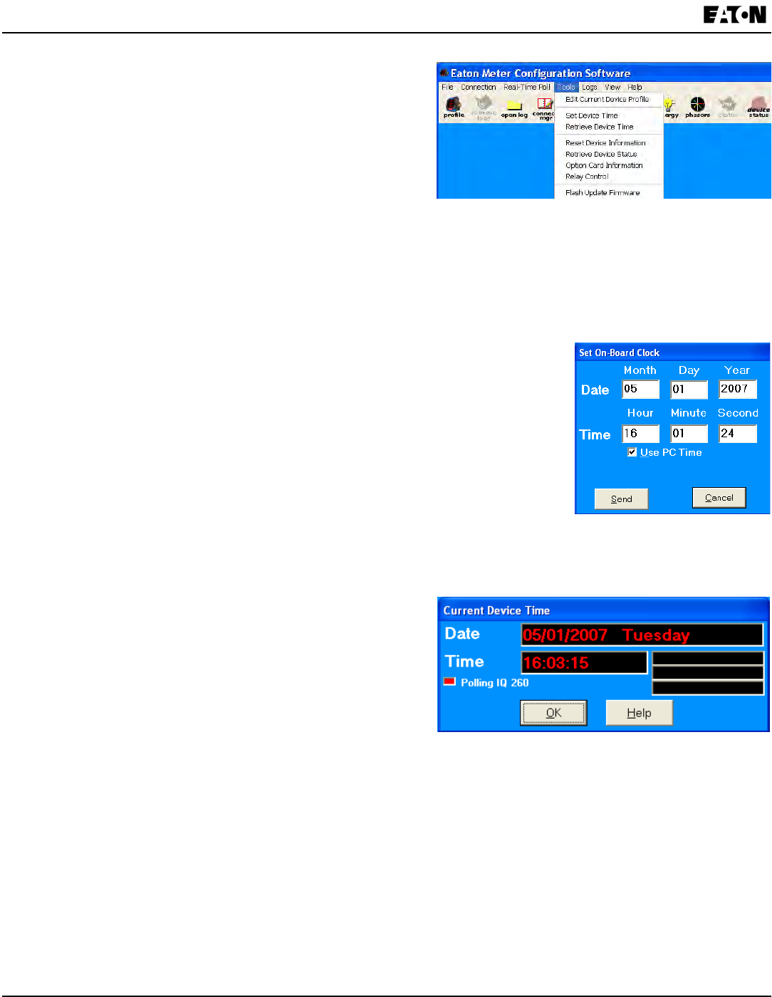
8-38 IB02601006E www.eaton.com
Chapter 8:
Programming the IQ 250/260 IQ 250/260 Meter
Using the IQ 250/260 Tools Menu
The Tools Menu allows you to access specic functions for
the IQ 250/260 Meter. Click Tools from the Title Bar to display
the Tools Menu.
Accessing the Device Prole Screen
Click the rst option, Edit Current Device Prole, to open the
Device Prole screen. This menu option performs the same
function as clicking the Prole icon in the Title Bar.
Setting Device Time
1. Click Tools>Set Device Time. You will see the screen shown on the right.
This screen allows you to set the meter’s internal clock and/or synchronize
it to your PC’s time. The meter’s clock is used for logging and other time
retrieval purposes.
2. You can enter a new Month, Day, and Year in the Date elds.
3. Check the box next to Use PC Time to synchronize the meter to your PC;
uncheck the box if you want to reset the time manually. You can then enter the
Hour, Minute, and Seconds you want in the Time elds.
4. Click Send to send the new date and/or time to the meter; click Cancel to close
the screen.
Retrieving Device Time
1. Click Tools>Retrieve Device Time. You will see the screen
shown on the right.
This screen displays the meter’s internal time. If Daylight
Savings Time is enabled, ‘DST’ will display in one of the
elds to the right of the Time eld.
2. Click OK to close the screen.
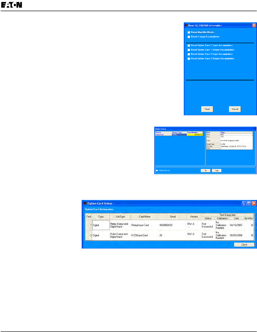
Chapter 8:
IQ 250/260 Meter Programming the IQ 250/260
www.eaton.com IB02601006E 8-39
Resetting Device Information
1. Click Tools>Reset Device Information. You will see the screen shown
on the right.
2. Select the items you want to reset and click Reset.
NOTES:
• You can reset Max/Min Blocks, Energy Accumulators, and Option Card
Accumulators.
• When installing a Pulse Output/Digital Input card or a Relay Output/Digital
Input card, we recommend you reset the accumulators for the card, in order
to prevent erroneous counts.
• This feature requires a Password if Password for Reset is enabled for the
meter.
Retrieving Device Status
1. Click Tools>Retrieve Device Status. you will see the screen
shown on the right.
NOTE: This is the same screen that opens when you rst c
onnect to the meter.
2. This screen shows the status of any connected devices. If
more than one meter is displayed, click on a device to display
detailed information for it on the right side of the scren.
3. Click OK to close the screen.
Viewing Option Card Information
1. Click Tools>Option Card
Information. You will see the
screen shown on the right.
This screen displays detailed
information about any Option
cards installed in the meter:
• Type
• Sub Type
• Card Name
• Serial Number
• Version
• Test Information.
2. Click Close to close the screen.
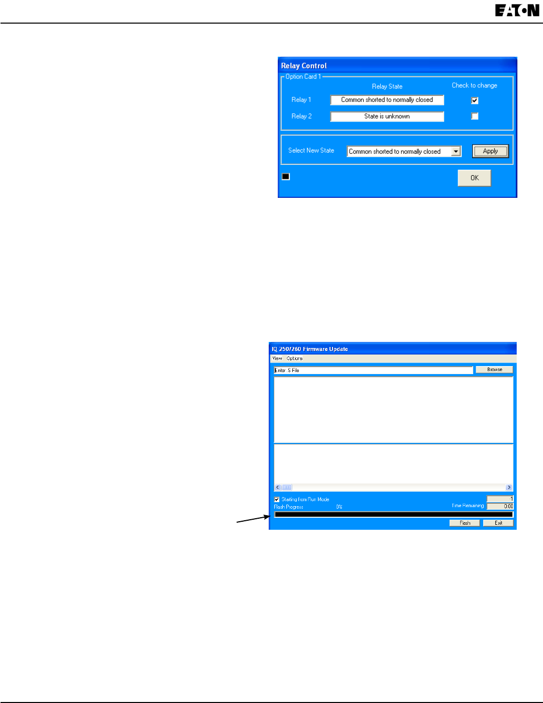
8-40 IB02601006E www.eaton.com
Chapter 8:
Programming the IQ 250/260 IQ 250/260 Meter
Performing Manual Relay Control
1. Click Tools>Relay Control. You will see the screen
shown on the right.
This screen allows you to manually set the state of
any installed Relay Output/Digital Input cards.
2. The screen displays the current Relay state. To
change the state:
a. Select the state you want in the Select New State
eld.
b. Click the checkbox next to the Relays you want to
change to the new state.
c. Click Apply.
NOTE: If this feature is Password Protected, the Enter Password screen opens.
3. Click OK to close the screen.
NOTES:
• A Relay cannot be manually controlled if a Limit has been assigned to it. See the instructions for
conguring a Relay Output/Digital Input Card, earlier in this chapter. (This only applies to the IQ 260 meter.)
• If the Relay State eld is “State is Unknown,” verify that the Relay conguration is correct. You may also
see this message after you have performed a Reset. Select a New State for the Relay and click Apply.
Performing Firmware Flash Update
1. Click Tools>Flash Me. You will see the screen
shown on the right.
This function allows you to update the IQ 250/260’s
rmware.
2. Click Browse to locate the ash le.
3. Click Flash to update the rmware with the ash le.
4. When Flash is complete, click Exit to close the
screen.
This Bar Shows Flashing Progress
NOTE: If Flash Update fails, you will see a message to that effect. Check Device Status (see instructions
on the previous page) to see if your meter is in Boot Mode.
• If the meter is in Boot Mode, uncheck the Starting from Run Mode box in the Flash Me screen and try ash
updating the rmware again.
• If the meter’s status is not displayed in the Device Status screen, the meter may be stuck in Boot Mode. If
you are certain the communication settings are correct for the meter, try connecting to the meter using the
following defaults:
Address 001
Baud Rate 9600
Protocol Modbus RTU
Once you connect to the meter, you can try ash upgrading again.
Flashing progress states and messages are
shown here: shows you current state of ashing
the rmware and any relevant output messages.
Communications messages display here
(messages being sent to the meter).
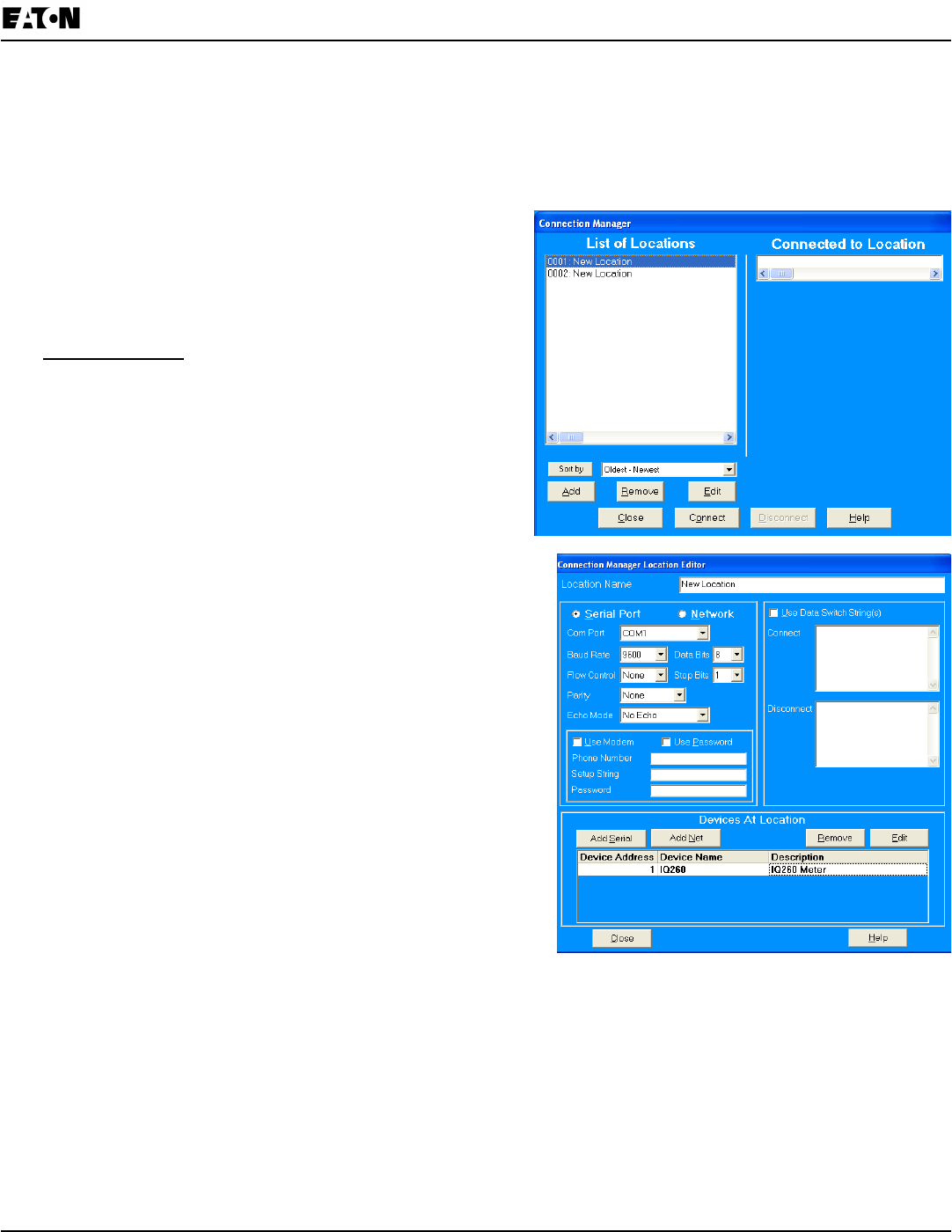
Chapter 8:
IQ 250/260 Meter Programming the IQ 250/260
www.eaton.com IB02601006E 8-41
Performing Additional Tasks with Eaton Meter Conguration Software
The following sections contain instructions for other tasks you can perform with the Eaton Meter Conguration
Software.
Using Connection Manager
Use Connection Manager to Add or Remove Connection
Locations and/or Devices at Locations.
1. Click Connection>Connection Manager or click on the
Connect Mgr icon. You will see the screen, shown on the
right.
List of Locations:
On the left side of the Connection Manager screen is a List
of Locations. These are the locations of one or more meters
to which you can connect. You can Add a Location and/or a
Device; Edit a Location and/or Device; or Remove a
Location and/or Device.
• To Add a Location:
a. Click on the Add button. You will see the Connection
Manager Location Editor screen. On this screen,
you program the Communication settings for each
New Location.
b. Type a Name for the New Location.
c. Click Serial Port or Network.
d. Enter Communications Settings:
Com Port: COM 1 - 99
Baud Rate: 1200 - 115200
Flow Control: None or Hardware
Data Bits: 8 (or 7)
Parity: None (Even, Odd)
e. To Add a Device:
- Click Add Serial (to add a Serial Port Connected Device)
or Add Net (to add a Network Connected Device) in the
Devices at Location box. You can add up to 255 Devices
(Serial Port and/or Network connected) at one Location.
NOTES:
• All devices must have the same connection parameters:
Baud, Parity and Flow Control.
• Multiple Devices slow down polling.
• If you are connecting to a device through the Power Xpert® Gateway, the protocol must be Modbus TCP.
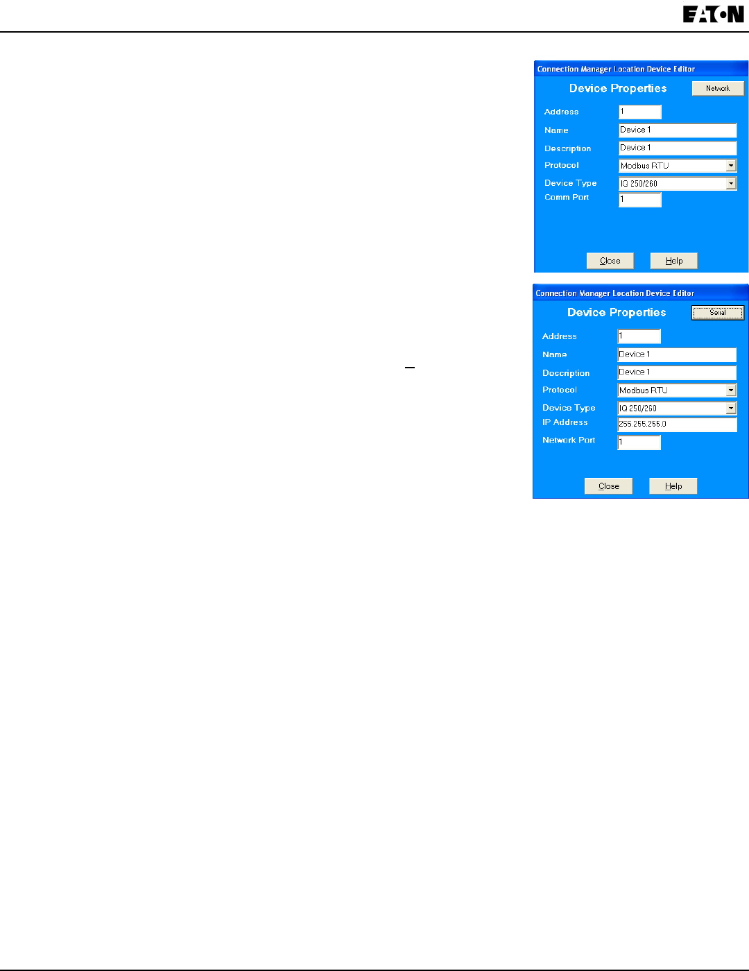
8-42 IB02601006E www.eaton.com
Chapter 8:
Programming the IQ 250/260 IQ 250/260 Meter
f. To Edit a Device:
- Select the Device from the Devices at Location box. (Scroll down to
nd all devices.)
- Click Edit. You will see the Connection Manager Location
Device Editor screen, shown on the right.
- Use this screen to program the Device Properties for each device at a
Location.
• If the Device has a Serial Port Device Connection, you will see the
rst (top) example screen.
• If the Device has a Network Device Connection, you will see the
second example screen.
Click the Network or Serial button at the top of the screen to switch
connection screens.
- Enter Device Properties:
Address: 1 - 247 (Unique Address)
Name: Device Name
Description: (Type and Number, for example)
Protocol: Modbus RTU, ASCII, or Modbus TCP (if connecting
to this device via the Power Xpert® Gateway, the
protocol must be Modbus TCP)
Device Type: IQ 250/260
Comm Port: 1 or 2 (Serial Port Only)
IP Address: 100.10.10.10 (for example) (Network Only)
Port Number: 502 (Default) (Network Only)
- Click Close to save settings and return to the Connection Manager
Location Editor screen.
g. To Remove a Device, select the Device from the Devices at Location box and click Remove.
h. Click Close to return to the Connection Manager screen.
• To Edit a Location:
a. Select a Location from the List of Locations box.
b. Click the Edit button. The Connection Manager Location Editor screen appears, displaying the current
settings for the location.
c. Make any changes to settings and/or devices at the location.
d. Click Close to exit the screen.
• To Remove a Location:
a. Select a Location from the List of Locations box.
b. Click Remove.
c. Click Yes in the Conrmation window.
• To Sort List of Locations:
a. Select a sort method (A-Z, Z-A, Newest-Oldest or Oldest-Newest) from the pull-down menu.
b. Click Sort By.
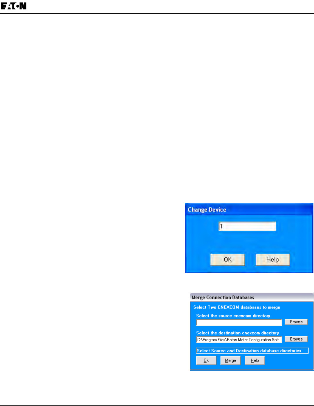
Chapter 8:
IQ 250/260 Meter Programming the IQ 250/260
www.eaton.com IB02601006E 8-43
• To Connect to a Location:
a. Select the Location you want to connect to from the List of Locations box.
NOTE: You may only connect to one location at a time. To change to a different location, you must disconnect
from the current location by selecting it and clicking Disconnect.
b. Click Connect. When the connection is made, the selected location appears in the Connected To Locations
section of the screen.
c. Click Close. The Device Status screen opens, conrming the connection. The Computer Status Bar at the
bottom of the screen also conrms the computer’s connection parameters.
NOTE: If the connection fails, a popup screen will alert you. Check that all cables are secure, that the RS-232 cable
is connected to the correct Com Port on the computer, and that the computer is set to use the same baud rate and
protocol as the meter to which the computer is connected.
Disconnecting from an IQ 250/260
To disconnect from an IQ 250/260 Meter or from a location, do one of the following:
• Click on the Disconnect icon in the Title Bar.
• Select Connection>Disconnect from the Title Bar.
• From the Connection Manager screen, select the location from the Connected to Location eld and click the
Disconnect button.
Changing the Primary Device/Address
Use this feature to select another meter as the primary device.
1. Click Connect>Change Primary Device/Address. You will
see the scree on the right.
2. Enter the address of the device you want to designate as the
new Primary Device.
3. Click OK.
Merging Connection Databases
Use this feature to combine two sets of cnexcom databases.
1. Click Connection>Merge Connection Databases. You will see
the screen on the right. It allows you to select the two databases
to merge.
2. Click the Browse button next to each eld to pick the databases.
The Source cnexcom database will be merged into the
Destination cnexcom database.
3. Click the Merge button to proceed with the merge; click OK to
exit the screen.
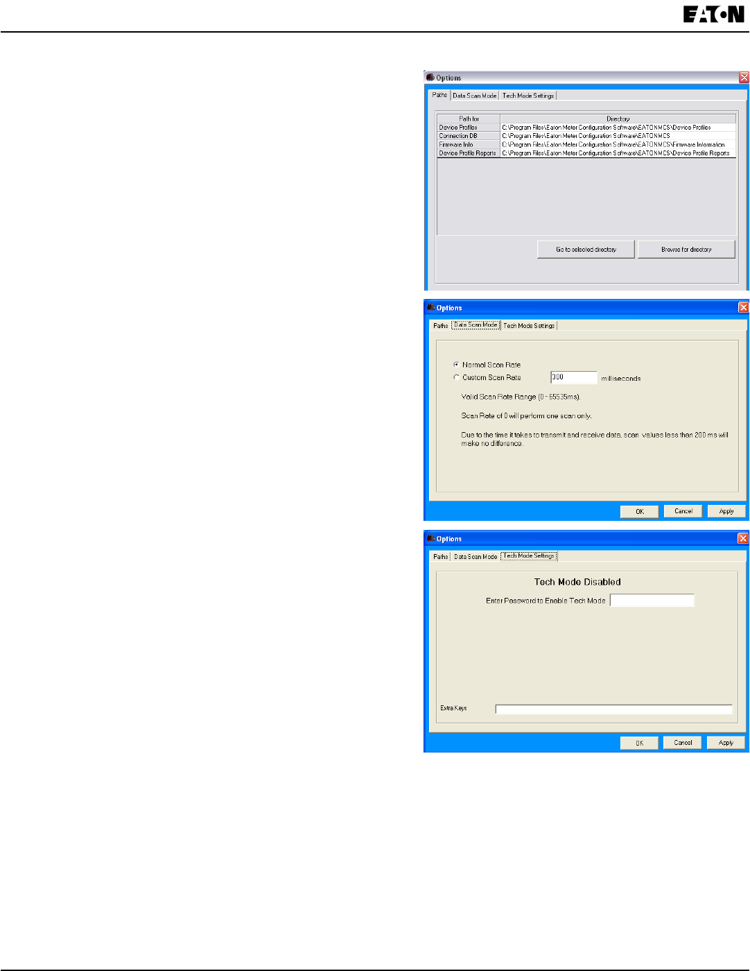
8-44 IB02601006E www.eaton.com
Chapter 8:
Programming the IQ 250/260 IQ 250/260 Meter
Using the Options Screen
1. Click View>Options. You will see the screen shown on the
right.
Use this screen to access the following features:
• Paths for Eaton Meter Conguration Software les
• Data Scan Mode
• Tech Mode Settings
Use the tabs at the top of the screen to access the features.
2. The rst Options screen is the Paths screen, shown on the
right. Use this screen to view or change the paths the
Eaton Meter Conguration Software uses for data.
3. Click the Data Scan Mode tab to see the second screen on
the right. Use this screen to select Normal Scan rate or to
enter a custom Scan rate.
4. Click the Tech Mode tab to see the third screen on the right.
Use this screen to access Tech Mode, by entering a valid
password.
5. Click:
• Apply to apply your selection(s) and keep the Options
screen open.
• Okay to apply your selection and close the Options screen.
• Cancel to close the Options screen without saving any
selections that have not been applied (using the Apply
button).
Using the Help Menu
The Help menu, accessed by clicking Help in the Title Bar,
allows you to:
• View this manual online: click Help>User Manual.
• View information about the Eaton Meter Conguration Software, including version number: click Help>About
Eaton Meter Conguration Software.

Appendix A:
IQ 250/260 Meter IQ 250/260 Navigation Maps
www.eaton.com IB02601006E A-1
App. A IQ250/260NavigationMaps
Introduction
YoucanconguretheIQ250/260andperformrelatedtasksusingthebuttonsonthemeterface.
•Chapter6containsadecriptionofthebuttonsonthemeterfaceandinstructionsforprogramming
themeterusingthem.
•Themetercanalsobeprogrammedusingsoftware.SeeChapter8forinstructionsonprogrammingthemeter
usingtheEatonMeterCongurationSoftware.
Navigation Maps (Sheets 1 to 4)
TheIQ250/260NavigationMapsbeginonthenextpage.Themapsshowindetailhowtomovefromonescreen
toanotherandfromoneDisplayModetoanotherusingthebuttonsonthefaceofthemeter.AllDisplayModeswill
automaticallyreturntoOperatingModeafter10minuteswithnouseractivity.
IQ 250/260 Navigation Map Titles:
•MainMenuScreens(Sheet1)
•OperatingModeScreens(Sheet2)
•ResetModeScreens(Sheet3)
•CongurationModeScreens(Sheet4)
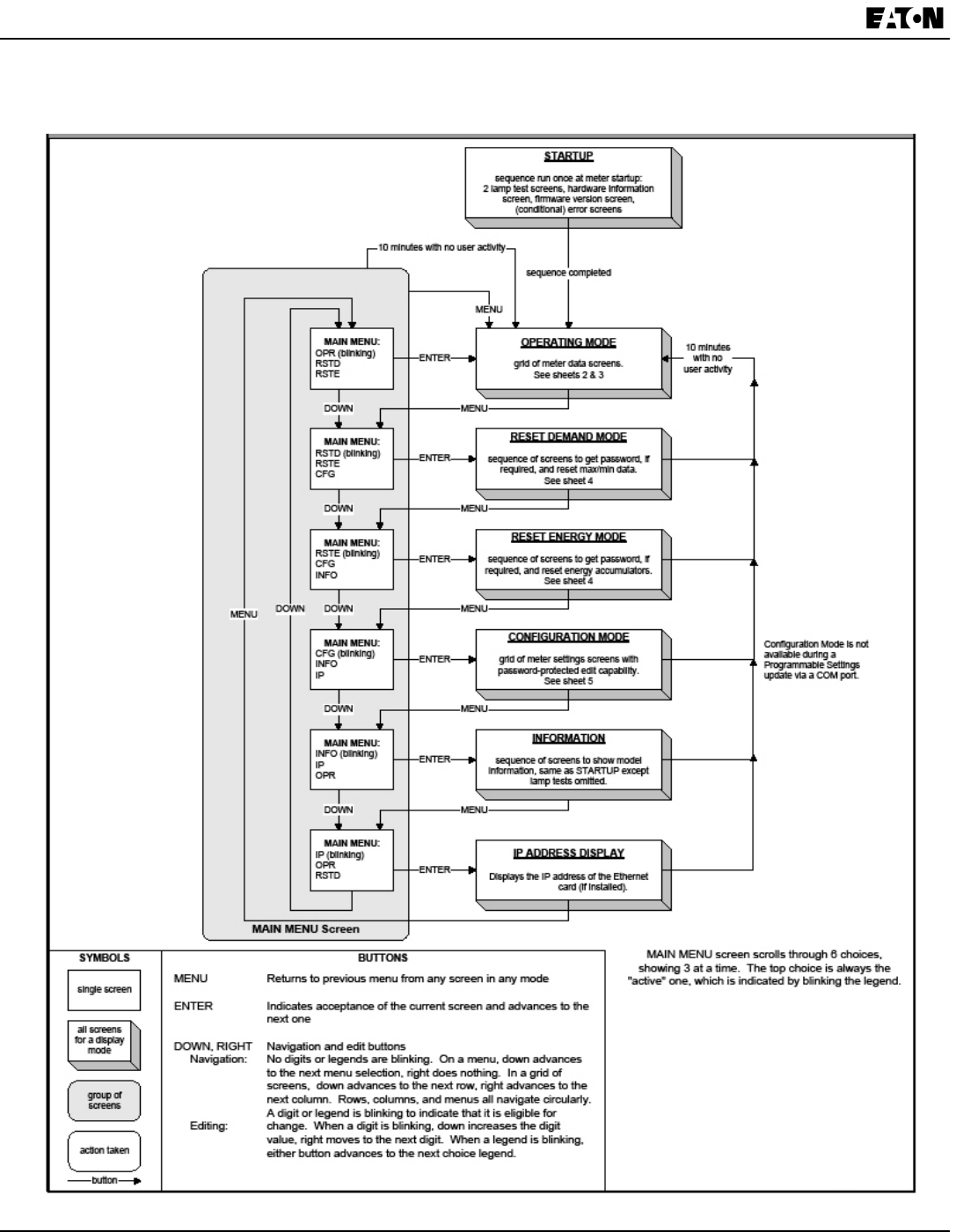
A-2 IB02601006E www.eaton.com
Appendix A:
IQ 250/260 Navigation Maps IQ 250/260 Meter
Main Menu Screens (Sheet 1)

Appendix A:
IQ 250/260 Meter IQ 250/260 Navigation Maps
www.eaton.com IB02601006E A-3
Operating Mode Screens (Sheet 2)
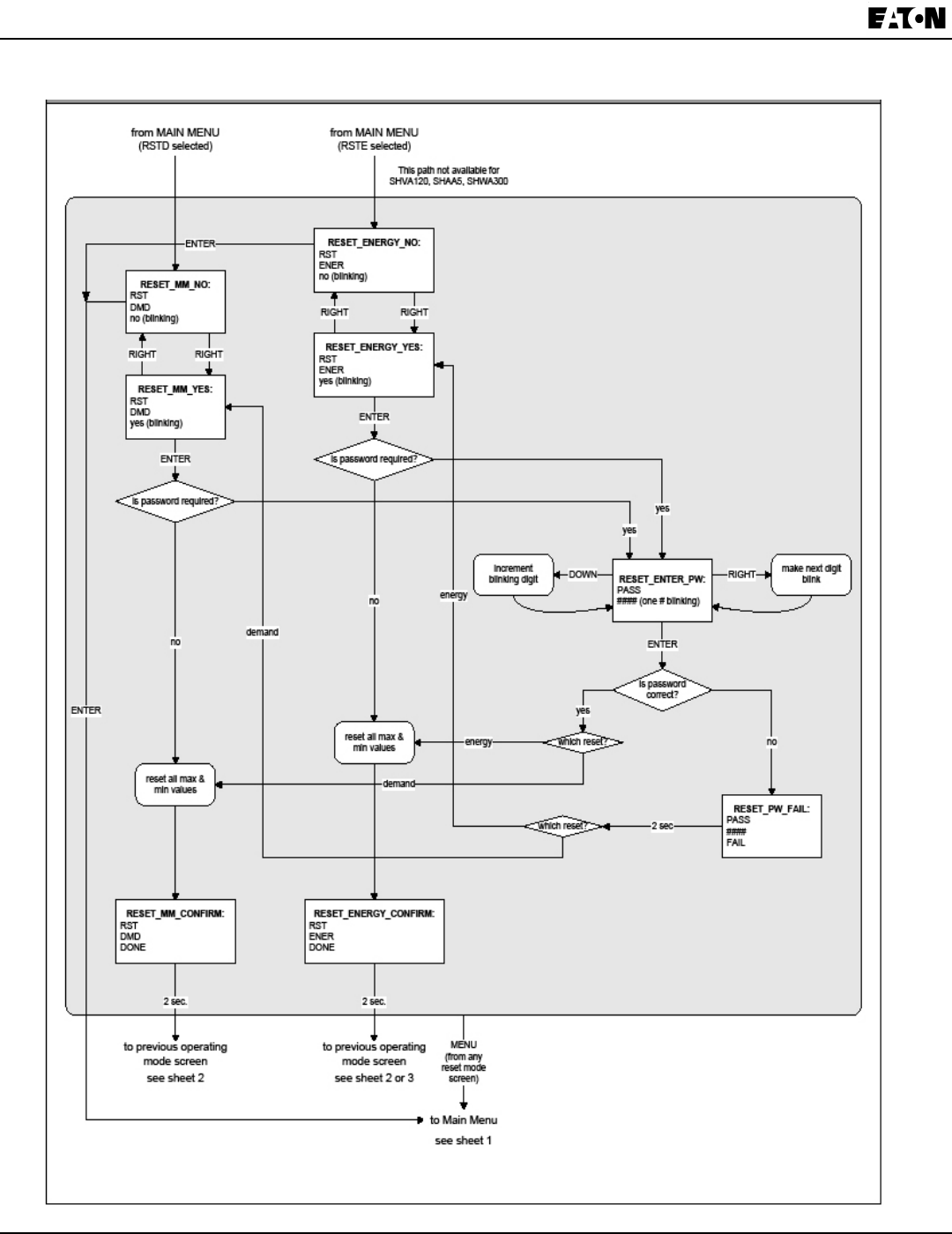
A-4 IB02601006E www.eaton.com
Appendix A:
IQ 250/260 Navigation Maps IQ 250/260 Meter
Reset Mode Screens (Sheet 3)
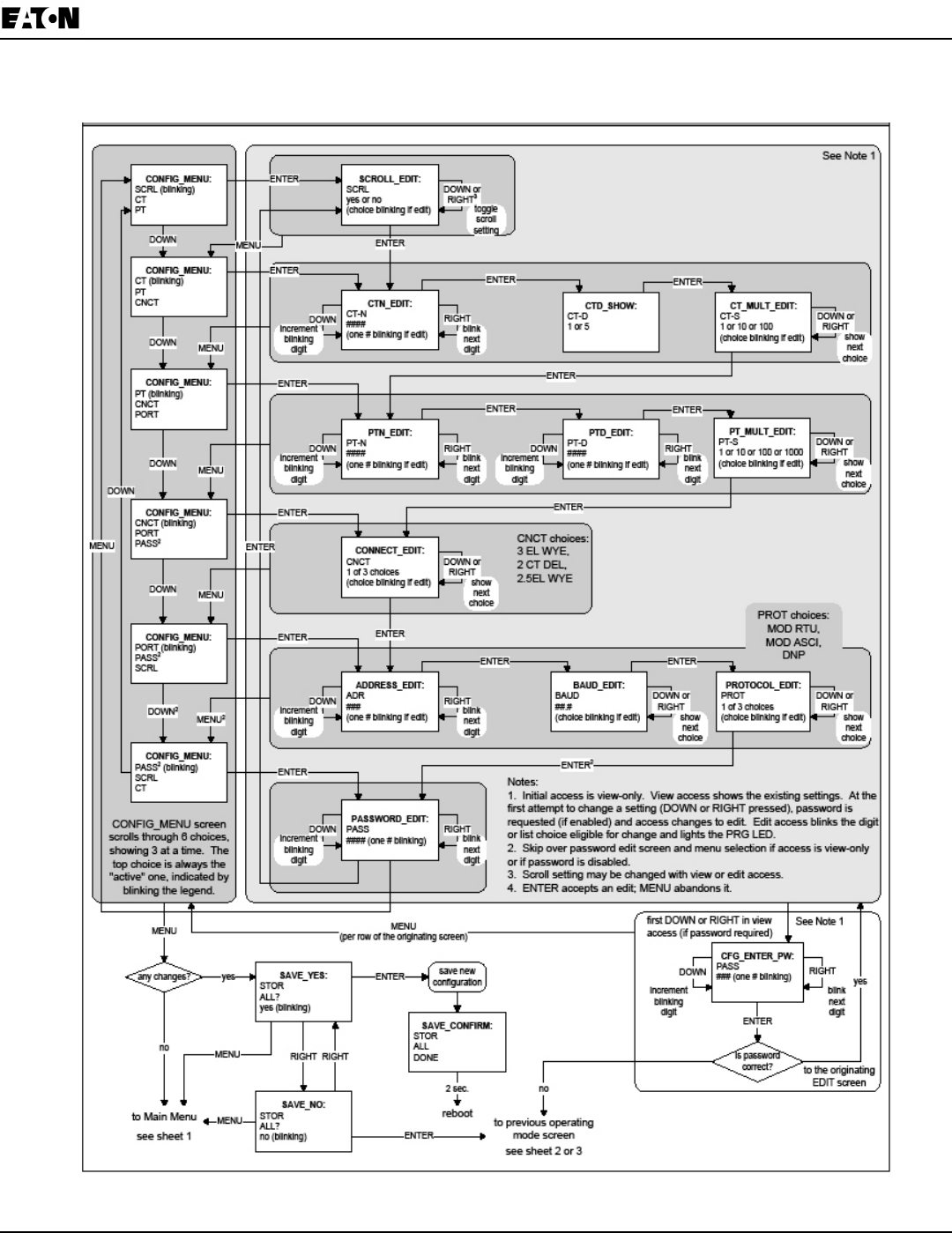
Appendix A:
IQ 250/260 Meter IQ 250/260 Navigation Maps
www.eaton.com IB02601006E A-5
Conguration Mode Screens (Sheet 4)

A-6 IB02601006E www.eaton.com
Appendix A:
IQ 250/260 Navigation Maps IQ 250/260 Meter

Appendix B:
IQ 250/260 Meter IQ 250/260 Modbus Map
www.eaton.com IB02601006E B-1
App.B IQ 250/260 Modbus Map
Introduction
The Modbus Map for the IQ 250/260 Meter gives details and information about the possible
readings of the meter and its programming. The IQ 250/260 can be programmed using the buttons
on the face of the meter (Chapter 6) or with the Eaton Meter Configuration Software (Chapter 8).
Modbus Register Map Sections
The IQ 250/260 Modbus Register Map includes the following sections:
Fixed Data Section, Registers 1- 47, details the Meter’s Fixed Information.
Meter Data Section, Registers 1000 - 12031, details the Meter’s Readings, including Primary
Readings, Energy Block, Demand Block, Phase Angle Block, Status Block, THD Block, Minimum
and Maximum in Regular and Time Stamp Blocks, Option Card Blocks, and Accumulators.
Operating Mode readings are described in Chapter 6 of this manual.
Commands Section, Registers 20000 - 26011, details the Meter’s Resets Block, Programming
Block, Other Commands Block and Encryption Block.
Programmable Settings Section, Registers 30000 - 33575, details all the setups you can program to
configure your meter.
Secondary Readings Section, Registers 40001 - 40100, details the Meter’s Secondary Readings.
Data Formats
ASCII: ASCII characters packed 2 per register in high, low order and without any
termination characters.
SINT16/UINT16: 16-bit signed/unsigned integer.
SINT32/UINT32: 32-bit signed/unsigned integer spanning 2 registers. The lower-addressed
register is the high order half.
FLOAT: 32-bit IEEE floating point number spanning 2 registers. The lower-addressed
register is the high order half (i.e., contains the exponent).
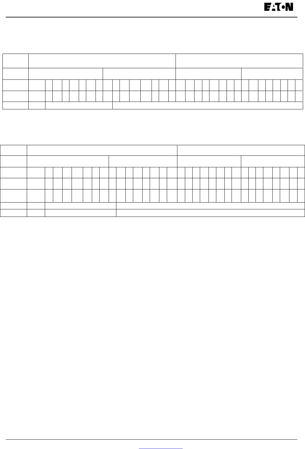
Appendix B:
Modbus Mapping for IQ 250/260 IQ 250/260 Meter
B-2 IB02601006E www.eaton.com
Floating Point Values
Floating Point Values are represented in the following format:
Register 0 1
Byte 0 1 0 1
Bit 7 6 5 4 3 2 1 0 7 6 5 4 3 2 1 0 7 6 5 4 3 2 1 0 7 6 5 4 3 2 1 0
Meaning s e e e e e e e e
m
mm m
m
m
m
mm
m
m
m
m
m
m
m
m
m
m
m
m
m
m
sign exponent mantissa
The formula to interpret a Floating Point Value is: -1sign x 2 exponent-127x1.mantissa = 0x0C4E11DB9
-1sign x 2 137-127 x 1· 1000010001110110111001
-1 x 210 x 1.75871956
-1800.929
Formula Explanation:
C4E11DB9 (hex) 11000100 11100001 00011101 10111001 (binary)
The sign of the mantissa (and therefore the number) is 1, which represents a negative
value.
The Exponent is 10001001 (binary) or 137 decimal.
The Exponent is a value in excess 127. So, the Exponent value is 10.
The Mantissa is 11000010001110110111001 binary.
With the implied leading 1, the Mantissa is (1).C23B72 (hex).
The Floating Point Representation is therefore -1.75871956 times 2 to the 10.
Decimal equivalent: -1800.929
NOTES:
• Exponent = the whole number before the decimal point.
• Mantissa = the positive fraction after the decimal point.
Register 0x0C4E1 0x01DB9
Byte 0x0C4 0x0E1 0x01D 0x0B9
Bit 7 6 5 4 3 2 1 0 7 6 5 4 3 2 1 0 7 6 5 4 3 2 1 0 7 6 5 4 3 2 1 0
1 1 0 0 0 1 0 0 1 1 1 0 0 0 0 1 0 0 0 1 1 1 0 1 1 0 1 1 1 0 0 1
Meaning s e e e e e e e e m
m
m
m
m
m
m
m
m
m
m
m
m
m
m
m
m
m
m
m
mm
m
sign exponent mantissa
1 0x089 + 137 0b011000010001110110111001

Appendix B:
IQ 250/260 Meter IQ 250/260 Modbus Map
www.eaton.com IB02601006E B-3
Important Note Concerning the IQ 250/260 Meter’s Modbus Map
In depicting Modbus Registers (Addresses), the IQ 250/260 meter’s Modbus map uses Holding Registers
only.
Hex Representation
The representation shown in the table below is used by developers of Modbus drivers and libraries, SEL
2020/2030 programmers and Firmware Developers. The IQ 250/260 meter’s Modbus map also uses this
representation.
Hex Description
0008 – 000F Meter Serial Number
Decimal Representation
The IQ 250/260 meter’s Modbus map defines Holding Registers as (4X) registers. Many popular SCADA
and HMI packages and their Modbus drivers have user interfaces that require users to enter these
Registers starting at 40001. So instead of entering two separate values, one for register type and one for
the actual register, they have been combined into one number.
The IQ 250/260 meter’s Modbus map uses a shorthand version to depict the decimal fields -i.e., not all of
the digits required for entry into the SCADA package UI are shown.
For Example:
You need to display the meter’s serial number in your SCADA application. The IQ 250/260 meter’s
Modbus map shows the following information for meter serial number:
Decimal Description
9 – 16 Meter Serial Number
In order to retrieve the meter’s serial number, enter 40009 into the SCADA UI as the starting register, and
8 as the number of registers.
In order to work with SCADA and Driver packages that use the 40001 to 49999 method for
requesting holding registers, take 40000 and add the value of the register (Address) in the
decimal column of the Modbus Map. Then enter the number (e.g., 4009) into the UI as the
starting register.
For SCADA and Driver packages that use the 400001 to 465536 method for requesting
holding registers take 400000 and add the value of the register (Address) in the decimal
column of the Modbus Map. Then enter the number (e.g., 400009) into the UI as the starting
register. The drivers for these packages strip off the leading four and subtract 1 from the
remaining value. This final value is used as the starting register or register to be included
when building the actual modbus message.
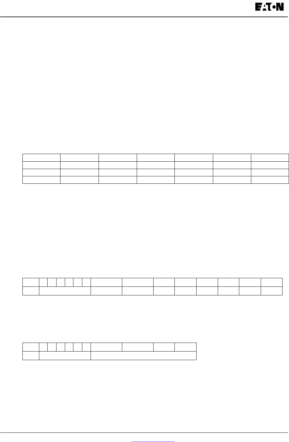
Appendix B:
Modbus Mapping for IQ 250/260 IQ 250/260 Meter
B-4 IB02601006E www.eaton.com
Retrieving Logs Using the IQ 250/260 Meter with Option L’s Modbus Map
This section describes the log interface system of the IQ 250/260 meters with the logging option from a
programming point of view. It is intended for Programmers implementing independent drivers for Log
Retrieval from the meter. It describes the meaning of the meter’s Modbus Registers related to Log
Retrieval and Conversion, and details the procedure for retrieving a log’s records.
NOTES:
All references assume the use of Modbus function codes 0x03, 0x06, and 0x10, where each
register is a 2 byte MSB (Most Significant Byte) word, except where otherwise noted.
The caret symbol (^) notation is used to indicate mathematical “power.” For example, 2^8
means 28; which is 2 x 2 x 2 x 2 x 2 x 2 x 2 x 2, which equals 256.
Data Formats
Timestamp: Stores a date from 2000 to 2099. Timestamp has a Minimum resolution of 1 second.
Byte 0 1 2 3 4 5
Value Year Month Day Hour Minute Second
Range 0-99 (+2000) 1-12 1-31 0-23 0-59 0-59
Mask 0x7F 0x0F 0x1F 0x1F 0x3F 0x3F
The high bits of each timestamp byte are used as flags to record meter state information at the time of the
timestamp. These bits should be masked out, unless needed.
IQ 250/260 Meter Logs
The IQ 250/260 meter has 2 logs: System Event and 1 Historical log. Each log is described below.
1) System Event ( 0 ) : The System Event log is used to store events which happen in, and to, the
meter. Events include Startup, Reset Commands, Log Retrievals, etc.
The System Event Log Record takes 20 bytes, 14 bytes of which are available when the log is
retrieved.
Byte 0 1 2 3 4 5 6 7 8 9 10 11 12 13
Value timestamp Group Event Mod Chan Param1 Param2 Param3 Param4
2) Historical Log ( 2 ) : The Historical Log records the values of its assigned registers at the
programmed interval.
NOTE: See Block Definitions (on the next page) for details on programming and interpreting the
log.
Byte 0 1 2 3 4 5 6 . . N
Value timestamp values . . .

Appendix B:
IQ 250/260 Meter IQ 250/260 Modbus Map
www.eaton.com IB02601006E B-5
Block Definitions
This section describes the Modbus Registers involved in retrieving and interpreting an IQ 250/260 meter’s
log. Other sections refer to certain ‘values’ contained in this section. See the corresponding value in this
section for details.
NOTES:
Register is the Modbus Register Address in 0-based Hexadecimal notation. To convert it to 1-
based decimal notation, convert from hex16 to decimal10 and add 1.
For example: 0x03E7 = 1000.
Size is the number of Modbus Registers (2 byte) in a block of data.
1) Historical Log Programmable Settings:
The Historical log is programmed using a list of Modbus Registers that will be copied into the
Historical Log record. In other words, the Historical Log uses a direct copy of the Modbus
Registers to control what is recorded at the time of record capture.
To supplement this, the programmable settings for the Historical Logs contain a list of descriptors,
which group registers into items. Each item descriptor lists the data type of the item, and the
number of bytes for that item. By combining these two lists, the Historical Log record can be
interpreted.
For example: Registers 0x03E7 and 0x03E8 are programmed to be recorded by the Historical
log. The matching descriptor gives the data type as float, and the size as 4 bytes. These
registers program the log to record “Primary Readings Volts A-N.”
Historical Log Blocks:
Start Register: 0x7917 (Historical Log 1)
Block Size: 192 registers per log (384 bytes)
The Historical log programmable settings are comprised of 3 blocks. Each Historical log block
is composed of 3 sections: The header, the list of registers to log, and the list of item
descriptors.
i. Header:
Registers: 0x7917 – 0x7918
Size: 2 registers
Byte 0 1 2 3
Value # Registers # Sectors Interval
# Registers: The number of registers to log in the record. The size of the record
in memory is [12 + (# Registers x 2)]. The size during normal log retrieval is [6 +
(# Registers x 2)]. If this value is 0, the log is disabled. Valid values are {0-117}.
# Sectors: The number of Flash Sectors allocated to this log. Each sector is
64kb, minus a sector header of 20 bytes. If this value is 0, the log is disabled.
Valid values are {0-15}.
Interval: The interval at which the Historical log’s Records are captured. This
value is an enumeration:

Appendix B:
Modbus Mapping for IQ 250/260 IQ 250/260 Meter
B-6 IB02601006E www.eaton.com
0x01 1 minute
0x02 3 minute
0x04 5 minute
0x08 10 minute
0x10 15 minute
0x20 30 minute
0x40 60 minute
0
End of Interval (EOI) Pulse: Setting the interval to EOI causes a record to be logged whenever an
EOI pulse event is generated. This is most commonly used in conjunction with the Digital I/O Option
Cards.
NOTE: The interval between records will not be even (fixed), and thus should not be used with
programs that expect a fixed interval.
ii. Register List:
Registers: 0x7919 – 0x798D
Size: 1 register per list item, 117 list items
The Register List controls what Modbus Registers are recorded in each record of the
Historical log. Since many items, such as Voltage, Energy, etc., take up more than 1
register, multiple registers need to be listed to record those items.
For example: Registers 0x03E7 and 0x03E8 are programmed to be recorded by the
historical log. These registers program the log to record “Primary Readings Volts A-N.”
Each unused register item should be set to 0x0000 or 0xFFFF to indicate that it
should be ignored.
The actual size of the record, and the number of items in the register list which are
used, is determined by the # registers in the header.
Each register item is the Modbus Address in the range of 0x0000 to 0xFFFF.
iii. Item Descriptor List:
Registers: 0x798E – 0x79C8
Size: 1 byte per item, 117 bytes (59 registers)
While the Register List describes what to log, the Item Descriptor List describes how to
interpret that information. Each descriptor describes a group of register items, and what
they mean.
Each descriptor is composed of 2 parts:
Type: The data type of this descriptor, such as signed integer, IEEE floating
point, etc. This is the high nibble of the descriptor byte, with a value in the range
of 0-14. If this value is 0xFF, the descriptor should be ignored.
ASCII: An ASCII string, or byte array
1 Bitmap: A collection of bit flags
2 Signed Integer: A 2’s
Complement integer
3 Float: An IEEE floating point
4 Energy: Special Signed Integer, where the value is
adjusted by the energy settings in the meter’s
Programmable Settings.

Appendix B:
IQ 250/260 Meter IQ 250/260 Modbus Map
www.eaton.com IB02601006E B-7
}
5 Unsigned Integer
6 Signed Integer 0.1 scale: Special Signed Integer, where
the value is divided by 10 to give a 0.1 scale.
7-14 Unused
15 Disabled: used as end list marker.
Size: The size in bytes of the item described. This number is used to determine
the pairing of descriptors with register items.
For example: If the first descriptor is 4 bytes, and the second descriptor is 2
bytes, then the first 2 register items belong to the 1st descriptor, and the 3rd
register item belongs to the 2nd descriptor.
NOTE: As can be seen from the example, above, there is not a 1-to-1 relation
between the register list and the descriptor list. A single descriptor may refer to
multiple register items.
Register Items Descriptors
0x03C7 Float, 4 byte
0x03C8
0x1234 Signed Int, 2 byte
NOTE: The sum of all descriptor sizes must equal the number of bytes in the
data portion of the Historical Log record.
2) Log Status Block:
The Log Status Block describes the current status of the log in question. There is one header block
for each of the logs. Each log’s header has the following base address:
Log Base Address
System: 0xC747
Historical 1: 0xC757
Bytes Value Type Range # Bytes
0 - 3 Max Records UINT32 0 to 4,294,967,294 4
4 - 7 Number of Records Used UINT32 1 to 4,294,967,294 4
8 - 9 Record Size in Bytes UINT16 4 to 250 2
10 - 11 Log Availability UINT16 2
12 - 17 Timestamp, First Record TSTAMP 1Jan2000 - 31Dec2099 6
18 - 23 Timestamp, Last Record TSTAMP 1Jan2000 - 31Dec2099 6
24 - 31 Reserved 8
Max Records: The maximum number of records the log can hold given the record
size, and sector allocation. The data type is an unsigned integer from 0 – 2^32.
# Records Used: The number of records stored in the log. This number will equal
the Max Records when the log has filled. This value will be set to 1 when the log is
reset. The data type is an unsigned integer from 1 – 2^32.

Appendix B:
Modbus Mapping for IQ 250/260 IQ 250/260 Meter
B-8 IB02601006E www.eaton.com
NOTE: The first record in every log before it has rolled over is a “dummy” record,
filled with all 0xFF’s. When the log is filled and rolls over, this record is overwritten.
Record Size: The number of bytes in this record, including the timestamp. The data
type is an unsigned integer in the range of 14 – 242.
Log Availability: A flag indicating if the log is available for retrieval, or if it is in use
by another port.
0 Log Available for retrieval
1 Not used
2 In use by COM2 (RS485)
3 In use by COM3 (Option Card 1)
4 In use by COM4 (Option Card 2)
0xFFFF Log Not Available - the log cannot be retrieved. This
indicates that the log is disabled.
NOTE: To query the port by which you are currently connected, use the
Port ID register:
Register: 0x1193
Size: 1 register
Description: A value from 1-4, which enumerates the port that the
requestor is currently connected on.
NOTES:
When Log Retrieval is engaged, the Log Availability value will be set to
the port that engaged the log. The Log Availability value will stay the
same until either the log has been disengaged, or 5 minutes have
passed with no activity. It will then reset to 0 (available).
Each log can only be retrieved by one port at a time.
Only one log at a time can be retrieved.
First Timestamp: Timestamp of the oldest record.
Last Timestamp: Timestamp of the newest record.
3) Log Retrieval Block:
The Log Retrieval Block is the main interface for retrieving logs. It is comprised of 2 parts: the
header and the window. The header is used to program the particular data the meter presents
when a log window is requested. The window is a sliding block of data that can be used to
access any record in the specified log.
Session Com Port: The IQ 250/260 meter’s Com Port which is currently retrieving
logs. Only one Com Port can retrieve logs at any one time.
Registers: 0xC34E – 0xC34E
Size: 1 register
0 No Session Active
1 Not used
2 COM2 (RS485)
3 COM3 (Communications Capable Option Card 1)
4 COM4 (Communications Capable Option Card 2)

Appendix B:
IQ 250/260 Meter IQ 250/260 Modbus Map
www.eaton.com IB02601006E B-9
To get the current Com Port, see the NOTE on querying the port, on the previous page.
i. The Log Retrieval Header is used to program the log to be retrieved, the record(s) of
that log to be accessed, and other settings concerning the log retrieval.
Registers: 0xC34F – 0xC350
Size: 2 registers
Log Number: The log to be retrieved. Write this value to set which log is being
retrieved.
0 System Events
1 Alarms
2 Historical Log
Enable: This value sets if a log retrieval session is engaged (locked for retrieval)
or disengaged (unlocked, read for another to engage). Write this value with
1(enable) to begin log retrieval. Write this value with 0(disable) to end log
retrieval.
0 Disable
1 Enable
Scope: Sets the amount of data to be retrieved for each record. The default
should be 0 (normal).
0 Normal
1 Timestamp Only
2 Image
Normal [0]: The default record. Contains a 6-byte timestamp at the
beginning, then N data bytes for the record data.
Timestamp [1]: The record only contains the 6-byte timestamp. This is most
useful to determine a range of available data for non-interval based logs,
such as System Events.
Image [2]: The full record, as it is stored in memory. Contains a 2-byte
checksum, 4-byte sequence number, 6-byte timestamp, and then N data
bytes for the record data.
Records Per Window: The number of records that fit evenly into a window.
This value is settable, as less than a full window may be used. This number tells
the retrieving program how many records to expect to find in the window.
(RecPerWindow x RecSize) = #bytes used in the window.
This value should be ((123 x 2) \ recSize), rounded down.
Bytes Value Type Format Description # Bytes
0 - 1 Log Number,
Enable, Scope
UINT16 nnnnnnnn esssssss nnnnnnnn - log to retrieve
e - retrieval session enable
sssssss - retrieval mode
2
2 - 3 Records per
Window, Number
of Repeats
UINT16 wwwwwwww nnnnnnnn wwwwwwww - records per window
nnnnnnnn - repeat count
2

Appendix B:
Modbus Mapping for IQ 250/260 IQ 250/260 Meter
B-10 IB02601006E www.eaton.com
For example, with a record size of 30, the RecPerWindow = ((123 x 2) \ 30) =
8.2 ~= 8
Number of Repeats: Specifies the number of repeats to use for the Modbus
Function Code 0x23 (35) (See next page for more information on this Function
Code). Since the meter must pre-build the response to each log window request,
this value must be set once, and each request must use the same repeat count.
Upon reading the last register in the specified window, the record index will
increment by the number of repeats, if auto-increment is enabled.
0 Disables auto-increment
1 No Repeat count, each request will only get 1 window.
2-8 2-8 windows returned for each Function Code 0x23
request.
Bytes Value Type Format Description # Bytes
0 - 3 Offset of First Record
in Window
UINT32 ssssssss nnnnnnnn
nnnnnnnn nnnnnnnn
ssssssss - window status
nn…nn - 24-bit record index
number.
4
4 - 249 Log Retrieve Window UINT16 246
ii. The Log Retrieval Window block is used to program the data you want to retrieve from
the log. It also provides the interface used to retrieve that data.
Registers: 0xC351 - 0xC3CD
Size: 125 registers
Window Status: The status of the current window. Since the time to prepare a
window may exceed an acceptable modbus delay (1 second), this acts as a state
flag, signifying when the window is ready for retrieval. When this value indicates
that the window is not ready, the data in the window should be ignored. Window
Status is Read-only, any writes are ignored.
0 Window is Ready
0xFF Window is Not Ready
Record Number: The record number of the first record in the data window.
Setting this value controls which records will be available in the data window.
When the log is engaged, the first (oldest) record is “latched.” This means
that record number 0 will always point to the oldest record at the time of
latching, until the log is disengaged (unlocked).
To retrieve the entire log using auto-increment, set this value to 0, and
retrieve the window repeatedly, until all records have been retrieved.
NOTES:
When auto-increment is enabled, this value will automatically increment so
that the window will “page” through the records, increasing by
RecordsPerWindow each time that the last register in the window is read.
When auto-increment is not enabled, this value must be written-to
manually, for each window to be retrieved.
Log Retrieval Data Window: The actual data of the records, arranged
according to the above settings.

Appendix B:
IQ 250/260 Meter IQ 250/260 Modbus Map
www.eaton.com IB02601006E B-11
Log Retrieval
Log Retrieval is accomplished in 3 basic steps:
1. Engage the log.
2. Retrieve each of the records.
3. Disengage the log.
Auto-Increment
In the traditional Modbus retrieval system, you write the index of the block of data to retrieve, then
read that data from a buffer (window). To improve the speed of retrieval, the index can be
automatically incremented each time the buffer is read.
In the IQ 250/260, when the last register in the data window is read, the record index is
incremented by the Records per Window.
Modbus Function Code 0x23
QUERY
Field Name Example (Hex)
Slave Address 01
Function 23
Starting Address Hi C3
Starting Address Lo 51
# Points Hi 00
# Points Lo 7D
Repeat Count 04
Function Code 0x23 is a user defined Modbus function code, which has a format similar to
Function Code 0x03, except for the inclusion of a “repeat count.” The repeat count (RC) is
used to indicate that the same N registers should be read RC number of times. (See the
Number of Repeats bullet on the previous page.)
NOTES:
By itself this feature would not provide any advantage, as the same data will be
returned RC times. However, when used with auto-incrementing, this function
condenses up to 8 requests into 1 request, which decreases communication
time, as fewer transactions are being made.
In the IQ 250/260 meter repeat counts are limited to 8 times for Modbus RTU,
and 4 times for Modbus ASCII.
The response for Function Code 0x23 is the same as for Function Code 0x03, with the data
blocks in sequence.
IMPORTANT: Before using function code 0x23, always check to see if the current connection
supports it. Some relay devices do not support user defined function codes; if that is the
case, the message will stall. Other devices don’t support 8 repeat counts.

Appendix B:
Modbus Mapping for IQ 250/260 IQ 250/260 Meter
B-12 IB02601006E www.eaton.com
Log Retrieval Procedure
The following procedure documents how to retrieve a single log from the oldest record to the newest
record, using the “normal” record type (see Scope). All logs are retrieved using the same method.
See following section for a Log Retrieval example.
NOTES:
This example uses auto-increment.
In this example, Function Code 0x23 is not used
You will find referenced topics in the Block Definitions section.
Modbus Register numbers are listed in brackets.
1. Engage the Log:
a) Read the Log Status Block.
i. Read the contents of the specific logs’ status block [0xC737+, 16 reg] (see Log
Headers).
ii. Store the # of Records Used, the Record Size, and the Log Availability.
iii. If the Log Availability is not 0, stop Log Retrieval; this log is not available at this time.
If Log Availability is 0, proceed to step 1b (Engage the log).
This step is done to ensure that the log is available for retrieval, as well as
retrieving information for later use.
b) Engage the log.
Write log to engage to Log Number, 1 to Enable, and the desired mode to Scope (default
0 (Normal)) [0xC34F, 1 reg]. This is best done as a single-register write.
This step will latch the first (oldest) record to index 0, and lock the log so that only
this port can retrieve the log, until it is disengaged.
c) Verify the log is engaged.
Read the contents of the specific logs’ status block [0xC737+, 16 reg] again to see if the
log is engaged for the current port (see Log Availability).
If the Log is not engaged for the current port, repeat step 1b (Engage the log).
d) Write the retrieval information.
i. Compute the number of records per window, as follows:
RecordsPerWindow = (246 \ RecordSize)
If using 0x23, set the repeat count to 2-8. Otherwise, set it to 1.
Since we are starting from the beginning for retrieval, the first record
index is 0.
ii. Write the Records per window, the Number of repeats (1), and Record Index (0)
[0xC350, 3 reg].
This step tells the meter what data to return in the window.
2. Retrieve the records:
a) Read the record index and window.
Read the record index, and the data window [0xC351, 125 reg].
If the meter Returns a Slave Busy Exception, repeat the request.
If the Window Status is 0xFF, repeat the request.
If the Window Status is 0, go to step 2b (Verify record index).
NOTES:
We read the index and window in 1 request to minimize communication time, and
to ensure that the record index matches the data in the data window returned.

Appendix B:
IQ 250/260 Meter IQ 250/260 Modbus Map
www.eaton.com IB02601006E B-13
Space in the window after the last specified record (RecordSize x
RecordPerWindow) is padded with 0xFF, and can be safely discarded.
b) Verify that the record index incremented by Records Per Window.
The record index of the retrieved window is the index of the first record in the window.
This value will increase by Records Per Window each time the window is read, so it
should be 0, N, N x 2, N x 3 . . . for each window retrieved.
If the record index matches the expected record index, go to step 2c (Compute
next expected record index).
If the record index does not match the expected record index, then go to step 1d
(Write the retrieval information), where the record index will be the same as the
expected record index. This will tell the meter to repeat the records you were
expecting.
c) Compute next Expected Record Index.
If there are no remaining records after the current record window, go to step 3
(Disengage the log).
Compute the next expected record index by adding Records Per Window, to the
current expected record index.
If this value is greater than the number of records, resize the window so it only
contains the remaining records and go to step 1d (Write the retrieval information),
where the Records Per Window will be the same as the remaining records.
3. Disengage the log:
Write the Log Number (of log being disengaged) to the Log Index and 0 to the Enable bit
[0xC34F, 1 reg].
Log Retrieval Example
The following example illustrates a log retrieval session. The example makes the following assumptions:
Log Retrieved is Historical Log (Log Index 2).
Auto-Incrementing is used.
Function Code 0x23 is not used (Repeat Count of 1).
The Log contains Volts-AN, Volts-BN, Volts-CN (12 bytes).
100 Records are available (0-99).
COM Port 2 (RS-485) is being used (see Log Availability).
There are no Errors.
Retrieval is starting at Record Index 0 (oldest record).
Protocol used is Modbus RTU. The checksum is left off for simplicity.
The IQ 250/260 meter is at device address 1.
No new records are recorded to the log during the log retrieval process.

Appendix B:
Modbus Mapping for IQ 250/260 IQ 250/260 Meter
B-14 IB02601006E www.eaton.com
1) Read [0xC757, 16 reg], Historical Log Header Block.
Send: 0103 C757 0010
Command:
-Register Address: 0xC757
-# Registers: 16
------------------------------
Receive: 010320 00000100 00000064 0012 0000 060717101511
060718101511 0000000000000000
Data:
-Max Records: 0x100 = 256 records maximum.
-Num Records: 0x64 = 100 records currently logged.
-Record Size: 0x12 = 18 bytes per record.
-Log Availability: 0x00 = 0, not in use, available for retrieval.
-First Timestamp: 0x060717101511 = July 23, 2006, 16:21:17
-Last Timestamp: 0x060717101511 = July 24, 2006, 16:21:17
NOTE: This indicates that Historical Log 1 is available for retrieval.
2) Write 0x0280 -> [0xC34F, 1 reg], Log Enable.
Send: 0106 C34F 0280
Command:
-Register Address: 0xC34F
-# Registers: 1 (Write Single Register Command)
Data:
-Log Number: 2 (Historical Log 1)
-Enable: 1 (Engage log)
-Scope: 0 (Normal Mode)
------------------------------
Receive: 0106C34F0280 (echo)
NOTE: This engages the log for use on this COM Port, and latches the oldest record as
record index 0.
3) Read [0xC757, 16 reg], Availability is 0.
Send: 0103 C757 0010
Command:
-Register Address: 0xC757
-# Registers: 16
------------------------------
Receive: 010320 00000100 00000064 0012 0002 060717101511
060718101511 0000000000000000
Data:
-Max Records: 0x100 = 256 records maximum.
-Num Records: 0x64 = 100 records currently logged.
-Record Size: 0x12 = 18 bytes per record.
-Log Availability: 0x02 = 2, In use by COM2, RS485 (the current port)
-First Timestamp: 0x060717101511 = July 23, 2006, 16:21:17
-Last Timestamp: 0x060717101511 = July 24, 2006, 16:21:17
NOTE: This indicates that the log has been engaged properly in step 2. Proceed to retrieve
the log.
4) Compute #RecPerWin as (246\18)=13. Write 0x0D01 0000 0000 -> [0xC350, 3 reg] Write
Retrieval Info. Set Current Index as 0.
Send: 0110 C350 0003 06 0D01 00 000000
Command:

Appendix B:
IQ 250/260 Meter IQ 250/260 Modbus Map
www.eaton.com IB02601006E B-15
-Register Address: 0xC350
-# Registers: 3, 6 bytes
Data:
-Records per Window: 13. Since the window is 246 bytes, and the record is 18
bytes, 246\18 = 13.66, which means that 13 records
evenly fit into a single window. This is 234 bytes, which
means later on, we only need to read 234 bytes (117
registers) of the window to retrieve the records.
-# of Repeats: 1. We are using auto-increment (so not 0), but not
function code 0x23.
-Window Status: 0 (ignore)
-Record Index: 0, start at the first record.
------------------------------
Receive: 0110C3500003 (command ok)
NOTES:
This sets up the window for retrieval; now we can start retrieving the records.
As noted above, we compute the records per window as 246\18 = 13.66, which is
rounded to 13 records per window. This allows the minimum number of requests to
be made to the meter, which increases retrieval speed.
5) Read [0xC351, 125 reg], first 2 reg is status/index, last 123 reg is window data. Status
OK.
Send: 0103 C351 007D
Command:
-Register Address: 0xC351
-# Registers: 0x7D, 125 registers
------------------------------
Receive: 0103FA 00000000
060717101511FFFFFFFFFFFFFFFFFFFFFFFF
06071710160042FAAACF42FAAD1842FAA9A8 . . .
Data:
-Window Status: 0x00 = the window is ready.
-Index: 0x00 = 0, The window starts with the 0’th record, which
is the oldest record.
-Record 0: The next 18 bytes is the 0’th record (filler).
-Timestamp: 0x060717101511, = July 23, 2006, 16:21:17
-Data: This record is the “filler” record. It is used by the meter
so that there is never 0 records. It should be ignored. It
can be identified by the data being all 0xFF.
NOTE: Once a log has rolled over, the 0’th record will be
a valid record, and the filler record will disappear.
-Record 1: The next 18 bytes is the 1’st record.
-Timestamp: 0x060717101600 July 23, 2006, 16:22:00
-Data:
-Volts AN: 0x42FAAACF, float = 125.33~
-Volts BN: 0x42FAAD18, float = 125.33~
-Volts CN: 0x42FAA9A8, float = 125.33~
. . . 13 records
NOTES:
This retrieves the actual window. Repeat this command as many times as necessary
to retrieve all of the records when auto-increment is enabled.
Note the filler record. When a log is reset (cleared) in the meter, the meter
always adds a first “filler” record, so that there is always at least 1 record in the log.
This “filler” record can be identified by the data being all 0xFF, and it being index 0.

Appendix B:
Modbus Mapping for IQ 250/260 IQ 250/260 Meter
B-16 IB02601006E www.eaton.com
If a record has all 0xFF for data, the timestamp is valid, and the index is NOT 0, then
the record is legitimate.
When the “filler” record is logged, its timestamp may not be “on the interval.” The next
record taken will be on the next “proper interval,” adjusted to the hour.
For example, if the interval is 1 minute, the first “real” record will be taken on the next
minute (no seconds). If the interval is 15 minutes, the next record will be taken at :15,
:30, :45, or :00 - whichever of those values is next in sequence.
6) Compare the index with Current Index.
NOTES:
The Current Index is 0 at this point, and the record index retrieved in step 5 is 0: thus
we go to step 8.
If the Current Index and the record index do not match, go to step 7. The data that
was received in the window may be invalid, and should be discarded.
7) Write the Current Index to [0xC351, 2 reg].
Send: 0110 C351 0002 04 00 00000D
Command:
-Register Address: 0xC351
-# Registers: 2, 4 bytes
Data:
-Window Status: 0 (ignore)
-Record Index: 0x0D = 13, start at the 14th record.
------------------------------
Receive: 0110C3510002 (command ok)
NOTES:
This step manually sets the record index, and is primarily used when an out-of-order
record index is returned on a read (step 6).
The example assumes that the second window retrieval failed somehow, and we need
to recover by requesting the records starting at index 13 again.
8) For each record in the retrieved window, copy and save the data for later
interpretation.
9) Increment Current Index by RecordsPerWindow.
NOTES:
This is the step that determines how much more of the log we need to retrieve.
On the first N passes, Records Per Window should be 13 (as computed in step 4),
and the current index should be a multiple of that (0, 13, 26, . . .). This amount will
decrease when we reach the end (see step 10).
If the current index is greater than or equal to the number of records (in this case 100),
then all records have been retrieved; go to step 12. Otherwise, go to step 10 to check
if we are nearing the end of the records.
10) If number records – current index < RecordsPerWindow, decrease to match.
NOTES:
Here we bounds-check the current index, so we don’t exceed the records available.
If the number of remaining records (#records – current index) is less than the Records
per Window, then the next window is the last, and contains less than a full window of
records. Make records per window equal to remaining records (#records-current

Appendix B:
IQ 250/260 Meter IQ 250/260 Modbus Map
www.eaton.com IB02601006E B-17
index). In this example, this occurs when current index is 91 (the 8’th window). There
are now 9 records available (100-91), so make Records per Window equal 9.
11) Repeat step 5 through 10.
NOTES:
Go back to step 5, where a couple of values have changed.
Pass CurIndex FirstRecIndex RecPerWindow
0 0 0 13
1 13 13 13
2 26 26 13
3 39 39 13
4 52 52 13
5 65 65 13
6 78 78 13
7 91 91 9
8 100 -- ---- -- -----
At pass 8, since Current Index is equal to the number of records (100), log retrieval
should stop; go to step 12 (see step 9 Notes).
12) No more records available, clean up.
13) Write 0x0000 -> [0xC34F, 1 reg], disengage the log.
Send: 0106 C34F 0000
Command:
-Register Address: 0xC34F
-# Registers: 1 (Write Single Register Command)
Data:
-Log Number: 0 (ignore)
-Enable: 0 (Disengage log)
-Scope: 0 (ignore)
------------------------------
Receive: 0106C34F0000 (echo)
NOTES:
This disengages the log, allowing it to be retrieved by other COM ports.
The log will automatically disengage if no log retrieval action is taken for 5 minutes.

Appendix B:
Modbus Mapping for IQ 250/260 IQ 250/260 Meter
B-18 IB02601006E www.eaton.com
Log Record Interpretation
The records of each log are composed of a 6 byte timestamp, and N data. The content of the data
portion depends on the log.
1. System Event Record:
Byte 0 1 2 3 4 5 6 7 8 9 10 11 12 13
Value timestamp Group Event Mod Chan Param1 Param2 Param3 Param4
Size: 14 bytes (20 bytes image).
Data: The System Event data is 8 bytes; each byte is an enumerated value.
Group: Group of the event.
Event: Event within a group.
Modifier: Additional information about the event, such as number of sectors or log
number.
Channel: The Port of the meter that caused the event.
0 Firmware
1 Not used
2 COM 2 (RS485)
3 COM 3 (Option Card 1)
4 COM 4 (Option Card 2)
7 User (Face Plate)
Param 1-4: These are defined for each event (see table on the next page).
NOTE: The System Log Record is 20 bytes, consisting of the Record Header (12 bytes) and
Payload (8 bytes). The Timestamp (6 bytes) is in the header. Typically, software will retrieve
only the timestamp and payload, yielding a 14-byte record. The table on the next page shows all
defined payloads.

Appendix B:
IQ 250/260 Meter IQ 250/260 Modbus Map
www.eaton.com IB02601006E B-19
Group
(Event
group)
Event
(Event
within
group)
Mod
(Event
modifier)
Channel
(1-4 for
COMs, 7
for USER,
0 for FW) Parm1 Parm2 Parm3 Parm4 Comments
0 Startup
0 0 0 FW version Meter Run Firmware Startup
1 slot# 0 class ID card status 0xFF 0xFF Option Card Using Default Settings
1 Log Activity
1 log# 1-4 0xFF 0xFF 0xFF 0xFF Reset
2 log# 1-4 0xFF 0xFF 0xFF 0xFF Log Retrieval Begin
3 log# 0-4 0xFF 0xFF 0xFF 0xFF Log Retrieval End
2 Clock Activity
1 0 1-4 0xFF 0xFF 0xFF 0xFF Clock Changed
2 0 0 0xFF 0xFF 0xFF 0xFF Daylight Time On
3 0 0 0xFF 0xFF 0xFF 0xFF Daylight Time Off
3 System Resets
1 0 0-4, 7 0xFF 0xFF 0xFF 0xFF Max & Min Reset
2 0 0-4, 7 0xFF 0xFF 0xFF 0xFF Energy Reset
3 slot# 0-4 1 (inputs)
or 2
(outputs)
0xFF 0xFF 0xFF Accumulators Reset
4 Settings Activity
1 0 1-4, 7 0xFF 0xFF 0xFF 0xFF Password Changed
2 0 1-4 0xFF 0xFF 0xFF 0xFF V-switch Changed
3 0 1-4, 7 0xFF 0xFF 0xFF 0xFF Programmable Settings Changed
4 0 1-4, 7 0xFF 0xFF 0xFF 0xFF Measurement Stopped
5 Boot Activity
1 0 1-4 FW version Exit to Boot
6 Error Reporting & Recovery
4 log # 0 0xFF 0xFF 0xFF 0xFF Log Babbling Detected
5 log # 0 # records discarded time in seconds Babbling Log Periodic Summary
6 log # 0 # records discarded time in seconds Log Babbling End Detected
7 sector# 0 error count stimulus 0xFF Flash Sector Error
8 0 0 0xFF 0xFF 0xFF 0xFF Flash Error Counters Reset
9 0 0 0xFF 0xFF 0xFF 0xFF Flash Job Queue Overflow
0x88
1 sector# 0 log # 0xFF 0xFF 0xFF acquire sector
2 sector# 0 log # 0xFF 0xFF 0xFF release sector
3 sector# 0 erase count erase sector
4 log# 0 0xFF 0xFF 0xFF 0xFF write log start record
log# values: 0 = system log, 1 = alarms log, 2-4 = historical logs 1-3, 5 = I/O change
log
sector# values: 0-63
slot# values: 1-2
NOTES:
o Stimulus for a flash sector error indicates what the flash was doing when the error
occurred: 1 = acquire sector, 2 = startup, 3 = empty sector, 4 = release sector, 5 = write
data

Appendix B:
Modbus Mapping for IQ 250/260 IQ 250/260 Meter
B-20 IB02601006E www.eaton.com
o Flash error counters are reset to zero in the unlikely event that both copies in EEPROM
are corrupted.
o A “babbling log” is one that is saving records faster than the meter can handle long term.
Onset of babbling occurs when a log fills a flash sector in less than an hour. For as long
as babbling persists, a summary of records discarded is logged every 60 minutes.
Normal logging resumes when there have been no new append attempts for 30 seconds.
o Logging of diagnostic records may be suppressed via a bit in programmable settings.
2. Historical Log Record:
Byte 0 1 2 3 4 5 6 . . N
Value timestamp values . . .
Size: 6+2 x N bytes (12+2 x N bytes), where N is the number of registers stored.
Data: The Historical Log Record data is 2 x N bytes, which contains snapshots of the values of
the associated registers at the time the record was taken. Since the meter uses specific
registers to log, with no knowledge of the data it contains, the Programmable Settings need
to be used to interpret the data in the record. See Historical Log Programmable Settings
for details.
Examples
a) Log Retrieval Section:
send: 01 03 75 40 00 08 - Meter designation
recv: 01 03 10 4D 65 74 72 65 44 65 73 69 6E 67 5F 20 20 20 20 00 00
send: :01 03 C7 57 00 10 - Historical Log status block
recv: :01 03 20 00 00 05 1E 00 00 05 1E 00 2C 00 00 06 08 17 51 08
00 06 08 18 4E 39 00 00 00 00 00 00 00 00 00 00 00
send: :01 03 79 17 00 40 - Historical Log PS settings
recv: :01 03 80 13 01 00 01 23 75 23 76 23 77 1F 3F 1F 40 1F 41 1F
42 1F 43 1F 44 06 0B 06 0C 06 0D 06 0E 17 75 17 76 17 77 18
67 18 68 18 69 00 00 00 00 00 00 00 00 00 00 00 00 00 00 00
00 00 00 00 00 00 00 00 00 00 00 00 00 00 00 00 00 00 00 00
00 00 00 00 00 00 00 00 00 00 00 00 00 00 00 00 00 00 00 00
00 00 00 00 00 00 00 00 00 00 00 00 00 00 00 00 00 00 00 00
00 00 00 00 00 00 00 00 00 00 00 00 00
send: :01 03 79 57 00 40 - ""
recv: :01 03 80 00 00 00 00 00 00 00 00 00 00 00 00 00 00 00 00 00
00 00 00 00 00 00 00 00 00 00 00 00 00 00 00 00 00 00 00 00
00 00 00 00 00 00 00 00 00 00 00 00 00 00 00 00 00 00 00 00
00 00 00 00 00 00 00 00 00 00 00 00 00 00 00 00 00 00 00 00
00 00 00 00 00 00 00 00 00 00 00 00 00 00 00 00 00 00 00 00
00 00 00 00 00 00 00 00 00 00 00 00 00 62 62 62 34 34 34 44
44 62 62 62 62 62 62 00 00 00 00 00 00
send: :01 03 75 35 00 01 - Energy PS settings
recv: :01 03 02 83 31 00 00
send: :01 03 11 93 00 01 - Connected Port ID
recv: :01 03 02 00 02 00 00

Appendix B:
IQ 250/260 Meter IQ 250/260 Modbus Map
www.eaton.com IB02601006E B-21
send: :01 03 C7 57 00 10 - Historical Log status block
recv: :01 03 20 00 00 05 1E 00 00 05 1E 00 2C 00 00 06 08 17 51 08
00 06 08 18 4E 39 00 00 00 00 00 00 00 00 00 00 00
send: :01 03 C3 4F 00 01 - Log Retrieval header
recv: :01 03 02 FF FF 00 00
send: :01 10 C3 4F 00 04 08 02 80 05 01 00 00 00 00 - Engage the log
recv: :01 10 C3 4F 00 04
send: :01 03 C7 57 00 10 - Historical Log status block
recv: :01 03 20 00 00 05 1E 00 00 05 1E 00 2C 00 02 06 08 17 51 08
00 06 08 18 4E 39 00 00 00 00 00 00 00 00 00 00 00
send: :01 10 C3 51 00 02 04 00 00 00 00 - Set the retrieval index
recv: :01 10 C3 51 00 02
send: :01 03 C3 51 00 40 - Read first half of window
recv: :01 03 80 00 00 00 00 06 08 17 51 08 00 00 19 00 2F 27 0F 00
00 00 00 00 00 00 00 00 00 00 00 00 00 00 00 00 00 00 00 03
E8 00 01 00 05 00 00 00 00 00 00 06 08 17 51 09 00 00 19 00
2F 27 0F 00 00 00 00 00 00 00 00 00 00 00 00 00 00 00 00 00
00 00 00 03 E8 00 01 00 04 00 00 00 00 00 00 06 08 17 51 0A
00 00 19 00 2F 27 0F 00 00 00 00 00 00 00 00 00 00 00 00 00
00 00 00 00 00 00 00 03 E8 00 00 00 00
send: :01 03 C3 91 00 30 - Read second half of window
recv: :01 03 60 00 05 00 00 00 00 00 00 06 08 17 51 0B 00 00 19 00
2F 27 0F 00 00 00 00 00 00 00 00 00 00 00 00 00 00 00 00 00
00 00 00 03 E8 00 01 00 04 00 00 00 00 00 00 06 08 17 51 0C
00 00 19 00 2F 27 0F 00 00 00 00 00 00 00 00 00 00 00 00 00
00 00 00 00 00 00 00 03 E8 00 01 00 04 00 00 00 00 00 00 00
00
send: :01 03 C3 51 00 40 - Read first half of last window
recv: :01 03 80 00 00 05 19 06 08 18 4E 35 00 00 19 00 2F 27 0F 00
00 00 00 00 00 00 00 00 00 00 00 00 00 00 00 00 00 00 00 03
E8 00 01 00 04 00 00 00 00 00 00 06 08 18 4E 36 00 00 19 00
2F 27 0F 00 00 00 00 00 00 00 00 00 00 00 00 00 00 00 00 00
00 00 00 03 E8 00 01 00 04 00 00 00 00 00 00 06 08 18 4E 37
00 00 19 00 2F 27 0F 00 00 00 00 00 00 00 00 00 00 00 00 00
00 00 00 00 00 00 00 03 E8 00 00 00 00
send: :01 03 C3 91 00 30 - Read second half of last window
recv: :01 03 60 00 05 00 00 00 00 00 00 06 08 18 4E 38 00 00 19 00
2F 27 0F 00 00 00 00 00 00 00 00 00 00 00 00 00 00 00 00 00
00 00 00 03 E8 00 01 00 04 00 00 00 00 00 00 06 08 18 4E 39
00 00 19 00 2F 27 0F 00 00 00 00 00 00 00 00 00 00 00 00 00
00 00 00 00 00 00 00 03 E8 00 00 00 05 00 00 00 00 00 00 00
00
send: :01 06 C3 4F 00 00 - Disengage the log
recv: :01 06 C3 4F 00 00

Appendix B:
Modbus Mapping for IQ 250/260 IQ 250/260 Meter
B-22 IB02601006E www.eaton.com
b) Sample Historical Log Record:
Historical Log Record and Programmable Settings
13|01|00 01|23 75|23 76|23 77|1F 3F 1F 40|1F 41
1F 42|1F 43 1F 44|06 0B 06 0C|06 0D 06 0E|17 75|
17 76|17 77|18 67|18 68|18 69|00 00 . . . . . .
62 62 62 34 34 34 44 44 62 62 62 62 62 62 . . .
These are the Item These are the These are the Descriptions:
Values: Type and Size:
13 - # registers
01 - # sectors
01 - interval
23 75 6 2 - (SINT 2 byte) Volts A THD Maximum
23 76 6 2 - (SINT 2 byte) Volts B THD Maximum
23 77 6 2 - (SINT 2 byte) Volts C THD Maximum
1F 3F 1F 40 3 4 - (Float 4 byte) Volts A Minimum
1F 41 1F 42 3 4 - (Float 4 byte) Volts B Minimum
1F 43 1F 44 3 4 - (Float 4 byte) Volts C Minimum
06 0B 06 0C 4 4 - (Energy 4 byte) VARhr Negative Phase A
06 0D 06 0E 4 4 - (Energy 4 byte) VARhr Negative Phase B
17 75 6 2 - (SINT 2 byte) Volts A 1st Harmonic
Magnitude
17 76 6 2 - (SINT 2 byte) Volts A 2nd Harmonic
Magnitude
17 77 6 2 - (SINT 2 byte) Volts A 3rd Harmonic
Magnitude
18 67 6 2 - (SINT 2 byte) Ib 3rd Harmonic Magnitude
18 68 6 2 - (SINT 2 byte) Ib 4th Harmonic Magnitude
18 69 6 2 - (SINT 2 byte) Ib 5th Harmonic Magnitude
Sample Record
06 08 17 51 08 00|00 19|00 2F|27 0F|00 00 00 00|00
00 00 00|00 00 00 00|00 00 00 00|00 00 00 00|03 E8|
00 01|00 05|00 00|00 00|00 00 . . .
06 08 17 51 08 00 - August 23, 2006 17:08:00
00 19 - 2.5%
00 2F - 4.7%
27 0F - 999.9% (indicates the value isn’t valid)
00 00 00 00 - 0
00 00 00 00 - 0
00 00 00 00 - 0
00 00 00 00 - 0
00 00 00 00 - 0
03 E8 - 100.0% (Fundamental)
00 01 - 0.1%
00 05 - 0.5%
00 00 - 0.0%
00 00 - 0.0%
00 00 - 0.0%

Appendix B:
IQ 250/260 Meter IQ 250/260 Modbus Map
www.eaton.com IB02601006E B-23
Modbus Register Map (MM-1 to MM-32)
The IQ 250/260 meter’s Modbus Register Map begins on the following page.

Appendix B:
Modbus Mapping for IQ 250/260 IQ 250/260 Meter
B-24 IB02601006E www.eaton.com
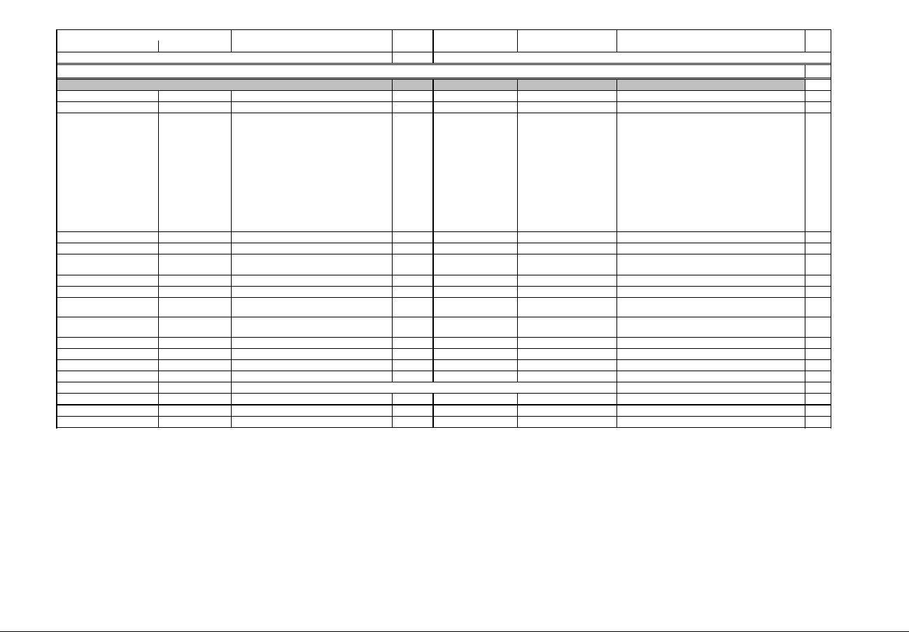
IQ 250/260 Meter App. B: Modbus Map
www.eaton.com IB02601006E MM-1
Description (Note 1) Format Range (Note 6) Units or Resolution Comments
read-only
0000 - 0007 1 - 8 Meter Name ASCII 16 char none 8
0008 - 000F 9 - 16 Meter Serial Number ASCII 16 char none 8
0010 - 0010 17 - 17 Meter Type UINT16 bit-mapped ------st -----vvv t = transducer model (1=yes, 0=no),
s= submeter model(1=yes,0=no),
vvv = IQ Model:
V40 = IQ 250,
V41 = IQ 260,
V48 = IQ 250L (with logging),
V49 = IQ 260L (with logging)
1
0011 - 0012 18 - 19 Firmware Version ASCII 4 char none 2
0013 - 0013 20 - 20 Map Version UINT16 0 to 65535 none 1
0014 - 0014 21 - 21 Meter Configuration UINT16 bit-mapped -----ccc --ffffff ccc = CT denominator (1 or 5),
ffffff = calibration frequency (50 or 60)
1
0015 - 0015 22 - 22 ASIC Version UINT16 0-65535 none 1
0016 - 0017 23 - 24 Boot Firmware Version ASCII 4 char none 2
0018 - 0018 25 - 25 Option Slot 1 Usage UINT16 bit-mapped same as register 10000
(0x270F)
1
0019 - 0019 26 - 26 Option Slot 2 Usage UINT16 bit-mapped same as register 11000
(0x2AF7)
1
001A - 001D 27 - 30 Meter Type Name ASCII 8 char none 4
001E - 0026 31 - 39 Reserved Reserved 9
0027 - 002E 40 - 47 Reserved Reserved 8
002F - 0115 48 - 278 Reserved Reserved 231
0116 - 0130 279 - 305
0131 - 01F3 306 - 500 Reserved Reserved 194
01F4 - 0203 501 - 516 Reserved Reserved 16
Modbus Address
Hex Decimal #
Reg
Fixed Data Section
Identification Block
Integer Readings Block occupies these registers, see below
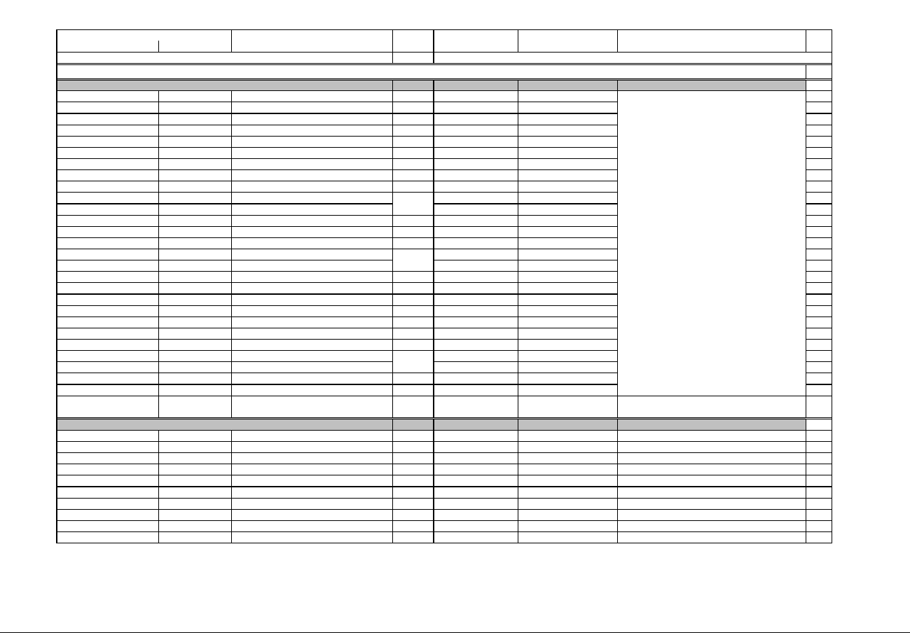
IQ 250/260 Meter App. B: Modbus Map
www.eaton.com IB02601006E MM-2
Description (Note 1) Format Range (Note 6) Units or Resolution Comments
Modbus Address
Hex Decimal #
Reg
read-only
0116 - 0116 279 - 279 Volts A-N UINT16 0 to 9999 volts 1
0117 - 0117 280 - 280 Volts B-N UINT16 0 to 9999 volts 1
0118 - 0118 281 - 281 Volts C-N UINT16 0 to 9999 volts 1
0119 - 0119 282 - 282 Volts A-B UINT16 0 to 9999 volts 1
011A - 011A 283 - 283 Volts B-C UINT16 0 to 9999 volts 1
011B - 011B 284 - 284 Volts C-A UINT16 0 to 9999 volts 1
011C - 011C 285 - 285 Amps A UINT16 0 to 9999 amps 1
011D - 011D 286 - 286 Amps B UINT16 0 to 9999 amps 1
011E - 011E 287 - 287 Amps C UINT16 0 to 9999 amps 1
011F - 011F 288 - 288 Neutral Current UINT16 -9999 to +9999 amps 1
0120 - 0120 289 - 289 Watts, 3-Ph total SINT16 -9999 to +9999 watts 1
0121 - 0121 290 - 290 VARs, 3-Ph total SINT16 -9999 to +9999 VARs 1
0122 - 0122 291 - 291 VAs, 3-Ph total UINT16 0 to +9999 VAs 1
0123 - 0123 292 - 292 Power Factor, 3-Ph total SINT16 -1000 to +1000 none 1
0124 - 0124 293 - 293 Frequency UINT16 0 to 9999 Hz 1
0125 - 0125 294 - 294 Watts, Phase A SINT16 -9999 M to +9999 watts 1
0126 - 0126 295 - 295 Watts, Phase B SINT16 -9999 M to +9999 watts 1
0127 - 0127 296 - 296 Watts, Phase C SINT16 -9999 M to +9999 watts 1
0128 - 0128 297 - 297 VARs, Phase A SINT16 -9999 M to +9999 M VARs 1
0129 - 0129 298 - 298 VARs, Phase B SINT16 -9999 M to +9999 M VARs 1
012A - 012A 299 - 299 VARs, Phase C SINT16 -9999 M to +9999 M VARs 1
012B - 012B 300 - 300 VAs, Phase A UINT16 0 to +9999 VAs 1
012C - 012C 301 - 301 VAs, Phase B UINT16 0 to +9999 VAs 1
012D - 012D 302 - 302 VAs, Phase C UINT16 0 to +9999 VAs 1
012E - 012E 303 - 303 Power Factor, Phase A SINT16 -1000 to +1000 none 1
012F - 012F 304 - 304 Power Factor, Phase B SINT16 -1000 to +1000 none 1
0130 - 0130 305 - 305 Power Factor, Phase C SINT16 -1000 to +1000 none 1
Block Size: 27
read-only
03E7 - 03E8 1000 - 1001 Volts A-N FLOAT 0 to 9999 M volts 2
03E9 - 03EA 1002 - 1003 Volts B-N FLOAT 0 to 9999 M volts 2
03EB - 03EC 1004 - 1005 Volts C-N FLOAT 0 to 9999 M volts 2
03ED - 03EE 1006 - 1007 Volts A-B FLOAT 0 to 9999 M volts 2
03EF - 03F0 1008 - 1009 Volts B-C FLOAT 0 to 9999 M volts 2
03F1 - 03F2 1010 - 1011 Volts C-A FLOAT 0 to 9999 M volts 2
03F3 - 03F4 1012 - 1013 Amps A FLOAT 0 to 9999 M amps 2
03F5 - 03F6 1014 - 1015 Amps B FLOAT 0 to 9999 M amps 2
03F7 - 03F8 1016 - 1017 Amps C FLOAT 0 to 9999 M amps 2
03F9 - 03FA 1018 - 1019 Watts, 3-Ph total FLOAT -9999 M to +9999 M watts 2
Readings Block ( Integer values)
1.Use the settings from Programmable settings for scale
and decimal point location. (see User Settings Flags)
2. Per phase power and PF have values
only for WYE hookup and will be
zero for all other hookups.
3. If the reading is 10000 that means that the value is out
of range. Please adjust the programmable settings in
that case. The display will also show '----' in case of over
range.
Primary Readings Block
Meter Data Section (Note 2)
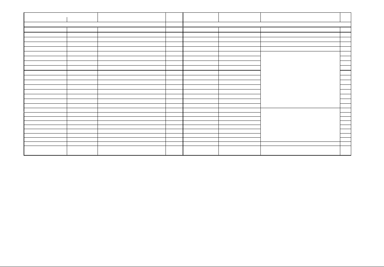
IQ 250/260 Meter App. B: Modbus Map
www.eaton.com IB02601006E MM-3
Description (Note 1) Format Range (Note 6) Units or Resolution Comments
Modbus Address
Hex Decimal #
Reg
03FB - 03FC 1020 - 1021 VARs, 3-Ph total FLOAT -9999 M to +9999 M VARs 2
03FD - 03FE 1022 - 1023 VAs, 3-Ph total FLOAT -9999 M to +9999 M VAs 2
03FF - 0400 1024 - 1025 Power Factor, 3-Ph total FLOAT -1.00 to +1.00 none 2
0401 - 0402 1026 - 1027 Frequency FLOAT 0 to 65.00 Hz 2
0403 - 0404 1028 - 1029 Neutral Current FLOAT 0 to 9999 M amps 2
0405 - 0406 1030 - 1031 Watts, Phase A FLOAT -9999 M to +9999 M watts 2
0407 - 0408 1032 - 1033 Watts, Phase B FLOAT -9999 M to +9999 M watts 2
0409 - 040A 1034 - 1035 Watts, Phase C FLOAT -9999 M to +9999 M watts 2
040B - 040C 1036 - 1037 VARs, Phase A FLOAT -9999 M to +9999 M VARs 2
040D - 040E 1038 - 1039 VARs, Phase B FLOAT -9999 M to +9999 M VARs 2
040F - 0410 1040 - 1041 VARs, Phase C FLOAT -9999 M to +9999 M VARs 2
0411 - 0412 1042 - 1043 VAs, Phase A FLOAT -9999 M to +9999 M VAs 2
0413 - 0414 1044 - 1045 VAs, Phase B FLOAT -9999 M to +9999 M VAs 2
0415 - 0416 1046 - 1047 VAs, Phase C FLOAT -9999 M to +9999 M VAs 2
0417 - 0418 1048 - 1049 Power Factor, Phase A FLOAT -1.00 to +1.00 none 2
0419 - 041A 1050 - 1051 Power Factor, Phase B FLOAT -1.00 to +1.00 none 2
041B - 041C 1052 - 1053 Power Factor, Phase C FLOAT -1.00 to +1.00 none 2
041D - 041E 1054 - 1055 Symmetrical Component Magnitude, 0 Seq FLOAT 0 to 9999 M volts 2
041F - 0420 1056 - 1057 Symmetrical Component Magnitude, + Seq FLOAT 0 to 9999 M volts 2
0421 - 0422 1058 - 1059 Symmetrical Component Magnitude, - Seq FLOAT 0 to 9999 M volts 2
0423 - 0423 1060 - 1060 Symmetrical Component Phase, 0 Seq SINT16 -1800 to +1800 0.1 degree 1
0424 - 0424 1061 - 1061 Symmetrical Component Phase, + Seq SINT16 -1800 to +1800 0.1 degree 1
0425 - 0425 1062 - 1062 Symmetrical Component Phase, - Seq SINT16 -1800 to +1800 0.1 degree 1
0426 - 0426 1063 - 1063 Unbalance, 0 sequence component UINT16 0 to 65535 0.01% 1
0427 - 0427 1064 - 1064 Unbalance, -sequence component UINT16 0 to 65535 0.01% 1
0428 - 0428 1065 - 1065 Current Unbalance UINT16 0 to 20000 0.01% 1
Block Size: 66
Per phase power and PF have values
only for WYE hookup and will be
zero for all other hookups.
Voltage unbalance per IEC6100-4.30
Values apply only to WYE hookup and
will be zero for all other hookups.

IQ 250/260 Meter App. B: Modbus Map
www.eaton.com IB02601006E MM-4
Description (Note 1) Format Range (Note 6) Units or Resolution Comments
Modbus Address
Hex Decimal #
Reg
read-only
05DB - 05DC 1500 - 1501 W-hours, Received SINT32 0 to 99999999 or
0 to -99999999
Wh per energy format 2
05DD - 05DE 1502 - 1503 W-hours, Delivered SINT32 0 to 99999999 or
0 to -99999999
Wh per energy format 2
05DF - 05E0 1504 - 1505 W-hours, Net SINT32 -99999999 to 99999999 Wh per energy format 2
05E1 - 05E2 1506 - 1507 W-hours, Total SINT32 0 to 99999999 Wh per energy format 2
05E3 - 05E4 1508 - 1509 VAR-hours, Positive SINT32 0 to 99999999 VARh per energy format 2
05E5 - 05E6 1510 - 1511 VAR-hours, Negative SINT32 0 to -99999999 VARh per energy format 2
05E7 - 05E8 1512 - 1513 VAR-hours, Net SINT32 -99999999 to 99999999 VARh per energy format 2
05E9 - 05EA 1514 - 1515 VAR-hours, Total SINT32 0 to 99999999 VARh per energy format 2
05EB - 05EC 1516 - 1517 VA-hours, Total SINT32 0 to 99999999 VAh per energy format 2
05ED - 05EE 1518 - 1519 W-hours, Received, Phase A SINT32 0 to 99999999 or
0 to -99999999
Wh per energy format 2
05EF - 05F0 1520 - 1521 W-hours, Received, Phase B SINT32 0 to 99999999 or
0 to -99999999
Wh per energy format 2
05F1 - 05F2 1522 - 1523 W-hours, Received, Phase C SINT32 0 to 99999999 or
0 to -99999999
Wh per energy format 2
05F3 - 05F4 1524 - 1525 W-hours, Delivered, Phase A SINT32 0 to 99999999 or
0 to -99999999
Wh per energy format 2
05F5 - 05F6 1526 - 1527 W-hours, Delivered, Phase B SINT32 0 to 99999999 or
0 to -99999999
Wh per energy format 2
05F7 - 05F8 1528 - 1529 W-hours, Delivered, Phase C SINT32 0 to 99999999 or
0 to -99999999
Wh per energy format 2
05F9 - 05FA 1530 - 1531 W-hours, Net, Phase A SINT32 -99999999 to 99999999 Wh per energy format 2
05FB - 05FC 1532 - 1533 W-hours, Net, Phase B SINT32 -99999999 to 99999999 Wh per energy format 2
05FD - 05FE 1534 - 1535 W-hours, Net, Phase C SINT32 -99999999 to 99999999 Wh per energy format 2
05FF - 0600 1536 - 1537 W-hours, Total, Phase A SINT32 0 to 99999999 Wh per energy format 2
0601 - 0602 1538 - 1539 W-hours, Total, Phase B SINT32 0 to 99999999 Wh per energy format 2
0603 - 0604 1540 - 1541 W-hours, Total, Phase C SINT32 0 to 99999999 Wh per energy format 2
0605 - 0606 1542 - 1543 VAR-hours, Positive, Phase A SINT32 0 to 99999999 VARh per energy format 2
0607 - 0608 1544 - 1545 VAR-hours, Positive, Phase B SINT32 0 to 99999999 VARh per energy format 2
0609 - 060A 1546 - 1547 VAR-hours, Positive, Phase C SINT32 0 to 99999999 VARh per energy format 2
060B - 060C 1548 - 1549 VAR-hours, Negative, Phase A SINT32 0 to -99999999 VARh per energy format 2
060D - 060E 1550 - 1551 VAR-hours, Negative, Phase B SINT32 0 to -99999999 VARh per energy format 2
060F - 0610 1552 - 1553 VAR-hours, Negative, Phase C SINT32 0 to -99999999 VARh per energy format 2
0611 - 0612 1554 - 1555 VAR-hours, Net, Phase A SINT32 -99999999 to 99999999 VARh per energy format 2
0613 - 0614 1556 - 1557 VAR-hours, Net, Phase B SINT32 -99999999 to 99999999 VARh per energy format 2
0615 - 0616 1558 - 1559 VAR-hours, Net, Phase C SINT32 -99999999 to 99999999 VARh per energy format 2
0617 - 0618 1560 - 1561 VAR-hours, Total, Phase A SINT32 0 to 99999999 VARh per energy format 2
0619 - 061A 1562 - 1563 VAR-hours, Total, Phase B SINT32 0 to 99999999 VARh per energy format 2
061B - 061C 1564 - 1565 VAR-hours, Total, Phase C SINT32 0 to 99999999 VARh per energy format 2
061D - 061E 1566 - 1567 VA-hours, Phase A SINT32 0 to 99999999 VAh per energy format 2
061F - 0620 1568 - 1569 VA-hours, Phase B SINT32 0 to 99999999 VAh per energy format 2
0621 - 0622 1570 - 1571 VA-hours, Phase C SINT32 0 to 99999999 VAh per energy format 2
Block Size: 72
Primary Energy Block
* Wh received & delivered always have opposite signs
* Wh received is positive for "view as load", delivered is
positive for "view as generator"
* 5 to 8 digits
* decimal point implied, per energy format
* resolution of digit before decimal point = units, kilo, or
mega, per energy format
* see note 10

IQ 250/260 Meter App. B: Modbus Map
www.eaton.com IB02601006E MM-5
Description (Note 1) Format Range (Note 6) Units or Resolution Comments
Modbus Address
Hex Decimal #
Reg
read-only
07CF - 07D0 2000 - 2001 Amps A, Average FLOAT 0 to 9999 M amps 2
07D1 - 07D2 2002 - 2003 Amps B, Average FLOAT 0 to 9999 M amps 2
07D3 - 07D4 2004 - 2005 Amps C, Average FLOAT 0 to 9999 M amps 2
07D5 - 07D6 2006 - 2007 Positive Watts, 3-Ph, Average FLOAT -9999 M to +9999 M watts 2
07D7 - 07D8 2008 - 2009 Positive VARs, 3-Ph, Average FLOAT -9999 M to +9999 M VARs 2
07D9 - 07DA 2010 - 2011 Negative Watts, 3-Ph, Average FLOAT -9999 M to +9999 M watts 2
07DB - 07DC 2012 - 2013 Negative VARs, 3-Ph, Average FLOAT -9999 M to +9999 M VARs 2
07DD - 07DE 2014 - 2015 VAs, 3-Ph, Average FLOAT -9999 M to +9999 M VAs 2
07DF - 07E0 2016 - 2017 Positive PF, 3-Ph, Average FLOAT -1.00 to +1.00 none 2
07E1 - 07E2 2018 - 2019 Negative PF, 3-PF, Average FLOAT -1.00 to +1.00 none 2
07E3 - 07E4 2020 - 2021 Neutral Current, Average FLOAT 0 to 9999 M amps 2
07E5 - 07E6 2022 - 2023 Positive Watts, Phase A, Average FLOAT -9999 M to +9999 M watts 2
07E7 - 07E8 2024 - 2025 Positive Watts, Phase B, Average FLOAT -9999 M to +9999 M watts 2
07E9 - 07EA 2026 - 2027 Positive Watts, Phase C, Average FLOAT -9999 M to +9999 M watts 2
07EB - 07EC 2028 - 2029 Positive VARs, Phase A, Average FLOAT -9999 M to +9999 M VARs 2
07ED - 07EE 2030 - 2031 Positive VARs, Phase B, Average FLOAT -9999 M to +9999 M VARs 2
07EF - 07F0 2032 - 2033 Positive VARs, Phase C, Average FLOAT -9999 M to +9999 M VARs 2
07F1 - 07F2 2034 - 2035 Negative Watts, Phase A, Average FLOAT -9999 M to +9999 M watts 2
07F3 - 07F4 2036 - 2037 Negative Watts, Phase B, Average FLOAT -9999 M to +9999 M watts 2
07F5 - 07F6 2038 - 2039 Negative Watts, Phase C, Average FLOAT -9999 M to +9999 M watts 2
07F7 - 07F8 2040 - 2041 Negative VARs, Phase A, Average FLOAT -9999 M to +9999 M VARs 2
07F9 - 07FA 2042 - 2043 Negative VARs, Phase B, Average FLOAT -9999 M to +9999 M VARs 2
07FB - 07FC 2044 - 2045 Negative VARs, Phase C, Average FLOAT -9999 M to +9999 M VARs 2
07FD - 07FE 2046 - 2047 VAs, Phase A, Average FLOAT -9999 M to +9999 M VAs 2
07FF - 0800 2048 - 2049 VAs, Phase B, Average FLOAT -9999 M to +9999 M VAs 2
0801 - 0802 2050 - 2051 VAs, Phase C, Average FLOAT -9999 M to +9999 M VAs 2
0803 - 0804 2052 - 2053 Positive PF, Phase A, Average FLOAT -1.00 to +1.00 none 2
0805 - 0806 2054 - 2055 Positive PF, Phase B, Average FLOAT -1.00 to +1.00 none 2
0807 - 0808 2056 - 2057 Positive PF, Phase C, Average FLOAT -1.00 to +1.00 none 2
0809 - 080A 2058 - 2059 Negative PF, Phase A, Average FLOAT -1.00 to +1.00 none 2
080B - 080C 2060 - 2061 Negative PF, Phase B, Average FLOAT -1.00 to +1.00 none 2
080D - 080E 2062 - 2063 Negative PF, Phase C, Average FLOAT -1.00 to +1.00 none 2
Block Size: 64
read-only
0BB7 - 0BB8 3000 - 3001 Watts, 3-Ph total FLOAT -9999 M to +9999 M watts 2
0BB9 - 0BBA 3002 - 3003 VARs, 3-Ph total FLOAT -9999 M to +9999 M VARs 2
0BBB - 0BBC 3004 - 3005 VAs, 3-Ph total FLOAT -9999 M to +9999 M VAs 2
0BBD - 0BBE 3006 - 3007 Power Factor, 3-Ph total FLOAT -1.00 to +1.00 none 2
Uncompensated Readings Block
Primary Demand Block

IQ 250/260 Meter App. B: Modbus Map
www.eaton.com IB02601006E MM-6
Description (Note 1) Format Range (Note 6) Units or Resolution Comments
Modbus Address
Hex Decimal #
Reg
0BBF - 0BC0 3008 - 3009 Watts, Phase A FLOAT -9999 M to +9999 M watts 2
0BC1 - 0BC2 3010 - 3011 Watts, Phase B FLOAT -9999 M to +9999 M watts 2
0BC3 - 0BC4 3012 - 3013 Watts, Phase C FLOAT -9999 M to +9999 M watts 2
0BC5 - 0BC6 3014 - 3015 VARs, Phase A FLOAT -9999 M to +9999 M VARs 2
OBC7 - 0BC8 3016 - 3017 VARs, Phase B FLOAT -9999 M to +9999 M VARs 2
0BC9 - 0BCA 3018 - 3019 VARs, Phase C FLOAT -9999 M to +9999 M VARs 2
0BCB - 0BCC 3020 - 3021 VAs, Phase A FLOAT -9999 M to +9999 M VAs 2
0BCD - 0BCE 3022 - 3023 VAs, Phase B FLOAT -9999 M to +9999 M VAs 2
0BCF - 0BD0 3024 - 3025 VAs, Phase C FLOAT -9999 M to +9999 M VAs 2
0BD1 - 0BD2 3026 - 3027 Power Factor, Phase A FLOAT -1.00 to +1.00 none 2
0BD3 - 0BD4 3028 - 3029 Power Factor, Phase B FLOAT -1.00 to +1.00 none 2
0BD5 - 0BD6 3030 - 3031 Power Factor, Phase C FLOAT -1.00 to +1.00 none 2
0BD7 - 0BD8 3032 - 3033 W-hours, Received SINT32 0 to 99999999 or
0 to -99999999
Wh per energy format 2
0BD9 - 0BDA 3034 - 3035 W-hours, Delivered SINT32 0 to 99999999 or
0 to -99999999
Wh per energy format 2
0BDB - 0BDC 3036 - 3037 W-hours, Net SINT32 -99999999 to 99999999 Wh per energy format 2
0BDD - 0BDE 3038 - 3039 W-hours, Total SINT32 0 to 99999999 Wh per energy format 2
0BDF - 0BE0 3040 - 3041 VAR-hours, Positive SINT32 0 to 99999999 VARh per energy format 2
0BE1 - 0BE2 3042 - 3043 VAR-hours, Negative SINT32 0 to -99999999 VARh per energy format 2
0BE3 - 0BE4 3044 - 3045 VAR-hours, Net SINT32 -99999999 to 99999999 VARh per energy format 2
0BE5 - 0BE6 3046 - 3047 VAR-hours, Total SINT32 0 to 99999999 VARh per energy format 2
0BE7 - 0BE8 3048 - 3049 VA-hours, Total SINT32 0 to 99999999 VAh per energy format 2
0BE9 - 0BEA 3050 - 3051 W-hours, Received, Phase A SINT32 0 to 99999999 or
0 to -99999999
Wh per energy format 2
0BEB - 0BEC 3052 - 3053 W-hours, Received, Phase B SINT32 0 to 99999999 or
0 to -99999999
Wh per energy format 2
0BED - 0BEE 3054 - 3055 W-hours, Received, Phase C SINT32 0 to 99999999 or
0 to -99999999
Wh per energy format 2
0BEF - 0BF0 3056 - 3057 W-hours, Delivered, Phase A SINT32 0 to 99999999 or
0 to -99999999
Wh per energy format 2
0BF1 - 0BF2 3058 - 3059 W-hours, Delivered, Phase B SINT32 0 to 99999999 or
0 to -99999999
Wh per energy format 2
0BF3 - 0BF4 3060 - 3061 W-hours, Delivered, Phase C SINT32 0 to 99999999 or
0 to -99999999
Wh per energy format 2
0BF5 - 0BF6 3062 - 3063 W-hours, Net, Phase A SINT32 -99999999 to 99999999 Wh per energy format 2
Per phase power and PF have values
only for WYE hookup and will be
zero for all other hookups.
* Wh received & delivered always have opposite signs
* Wh received is positive for "view as load", delivered is
positive for "view as generator"
* 5 to 8 digits
* decimal point implied, per energy format
* resolution of digit before decimal point = units, kilo, or
mega, per energy format
* see note 10
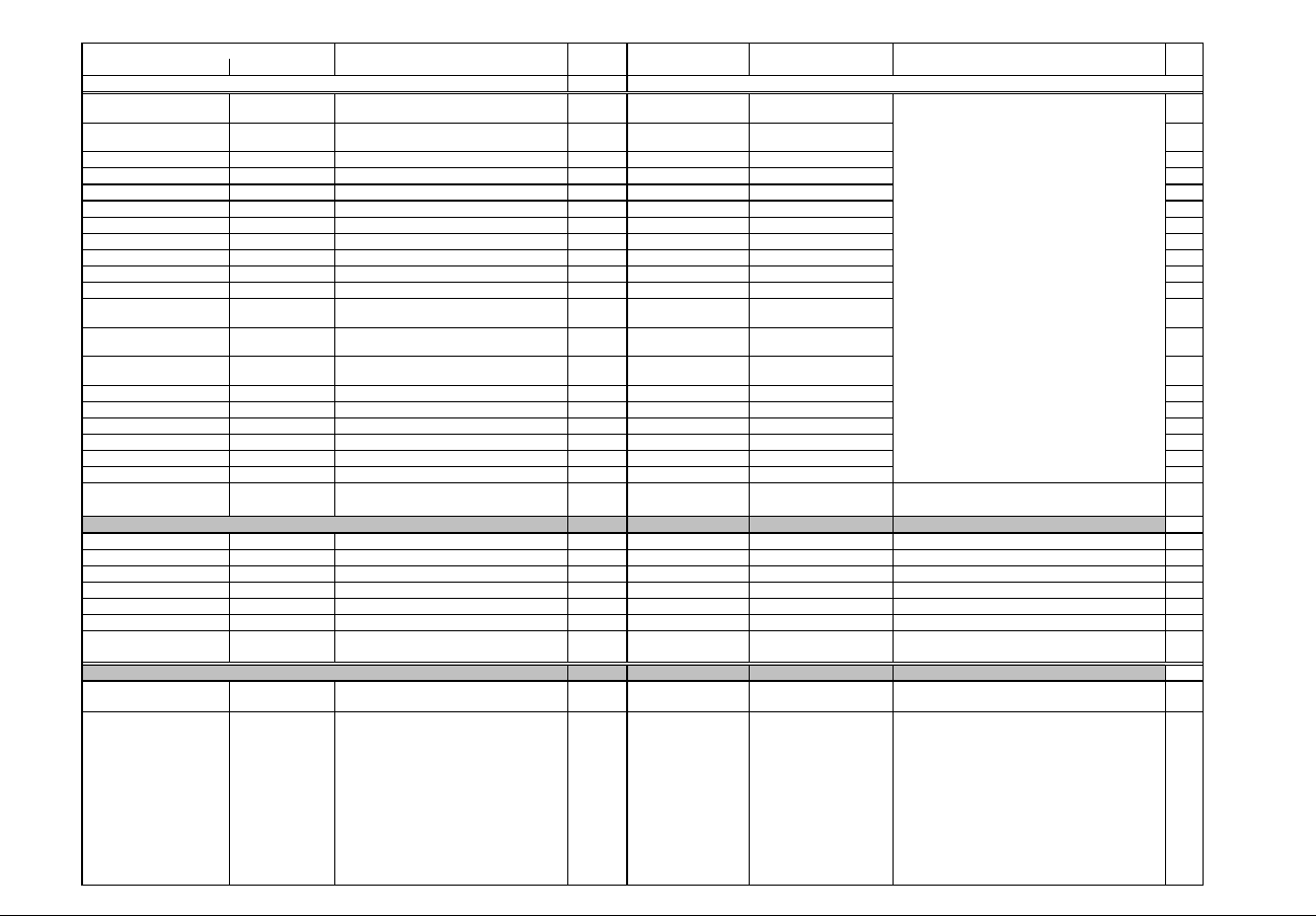
IQ 250/260 Meter App. B: Modbus Map
www.eaton.com IB02601006E MM-7
Description (Note 1) Format Range (Note 6) Units or Resolution Comments
Modbus Address
Hex Decimal #
Reg
0BF7 - 0BF8 3064 - 3065 W-hours, Net, Phase B SINT32 -99999999 to 99999999 Wh per energy format 2
0BF9 - 0BFA 3066 - 3067 W-hours, Net, Phase C SINT32 -99999999 to 99999999 Wh per energy format 2
0BFB - 0BFC 3068 - 3069 W-hours, Total, Phase A SINT32 0 to 99999999 Wh per energy format 2
0BFD - 0BFE 3070 - 3071 W-hours, Total, Phase B SINT32 0 to 99999999 Wh per energy format 2
0BFF - 0C00 3072 - 3073 W-hours, Total, Phase C SINT32 0 to 99999999 Wh per energy format 2
0C01 - 0C02 3074 - 3075 VAR-hours, Positive, Phase A SINT32 0 to 99999999 VARh per energy format 2
0C03 - 0C04 3076 - 3077 VAR-hours, Positive, Phase B SINT32 0 to 99999999 VARh per energy format 2
0C05 - 0C06 3078 - 3079 VAR-hours, Positive, Phase C SINT32 0 to 99999999 VARh per energy format 2
0C07 - 0C08 3080 - 3081 VAR-hours, Negative, Phase A SINT32 0 to -99999999 VARh per energy format 2
0C09 - 0C0A 3082 - 3083 VAR-hours, Negative, Phase B SINT32 0 to -99999999 VARh per energy format 2
0C0B - 0C0C 3084 - 3085 VAR-hours, Negative, Phase C SINT32 0 to -99999999 VARh per energy format 2
0C0D - 0C0E 3086 - 3087 VAR-hours, Net, Phase A SINT32 -99999999 to 99999999 VARh per energy format 2
0C0F - 0C10 3088 - 3089 VAR-hours, Net, Phase B SINT32 -99999999 to 99999999 VARh per energy format 2
0C11 - 0C12 3090 - 3091 VAR-hours, Net, Phase C SINT32 -99999999 to 99999999 VARh per energy format 2
0C13 - 0C14 3092 - 3093 VAR-hours, Total, Phase A SINT32 0 to 99999999 VARh per energy format 2
0C15 - 0C16 3094 - 3095 VAR-hours, Total, Phase B SINT32 0 to 99999999 VARh per energy format 2
0C17 - 0C18 3096 - 3097 VAR-hours, Total, Phase C SINT32 0 to 99999999 VARh per energy format 2
0C19 - 0C1A 3098 - 3099 VA-hours, Phase A SINT32 0 to 99999999 VAh per energy format 2
0C1B - 0C1C 3100 - 3101 VA-hours, Phase B SINT32 0 to 99999999 VAh per energy format 2
0C1D - 0C1E 3102 - 3103 VA-hours, Phase C SINT32 0 to 99999999 VAh per energy format 2
Block Size: 104
read-only
1003 - 1003 4100 - 4100 Phase A Current SINT16 -1800 to +1800 0.1 degree 1
1004 - 1004 4101 - 4101 Phase B Current SINT16 -1800 to +1800 0.1 degree 1
1005 - 1005 4102 - 4102 Phase C Current SINT16 -1800 to +1800 0.1 degree 1
1006 - 1006 4103 - 4103 Angle, Volts A-B SINT16 -1800 to +1800 0.1 degree 1
1007 - 1007 4104 - 4104 Angle, Volts B-C SINT16 -1800 to +1800 0.1 degree 1
1008 - 1008 4105 - 4105 Angle, Volts C-A SINT16 -1800 to +1800 0.1 degree 1
Block Size: 6
read-only
1193 - 1193 4500 - 4500 Port ID UINT16 1 to 4 none Identifies which COM port a master is connected to; 1 for
COM1, 2 for COM2, etc.
1
1194 - 1194 4501 - 4501 Meter Status UINT16 bit-mapped mmmpch-- tffeeccc mmm = measurement state (0=off, 1=running normally,
2=limp mode, 3=warmup, 6&7=boot, others unused)
See note 16.
pch = NVMEM block OK flags (p=profile, c=calibration,
h=header), flag is 1 if OK
t - CT PT compensation status. (0=Disabled,1=Enabled)
ff = flash state (0=initializing, 1=logging disabled by
model option, 3=logging)
ee = edit state (0=startup, 1=normal, 2=privileged
command session, 3=profile update mode)
ccc = port enabled for edit(0=none, 1-4=COM1-COM4,
7=front panel)
1
Phase Angle Block
Status Block

IQ 250/260 Meter App. B: Modbus Map
www.eaton.com IB02601006E MM-8
Description (Note 1) Format Range (Note 6) Units or Resolution Comments
Modbus Address
Hex Decimal #
Reg
1195 - 1195 4502 - 4502 Limits Status UINT16 bit-mapped 87654321 87654321 high byte is setpt 1, 0=in, 1=out
low byte is setpt 2, 0=in, 1=out
see notes 11, 12, 17
1
1196 - 1197 4503 - 4504 Time Since Reset UINT32 0 to 4294967294 4 msec wraps around after max count 2
1198 - 119A 4505 - 4507 Meter On Time TSTAMP 1Jan2000 - 31Dec2099 1 sec 3
119B - 119D 4508 - 4510 Current Date and Time TSTAMP 1Jan2000 - 31Dec2099 1 sec 3
119E - 119E 4511 - 4511 Clock Sync Status UINT16 bit-mapped mmm0 0ppe 0000 000s mmm00ppe = configuration per programmable settings
(see register 30011, 0x753A)
s = status: 1=working properly, 0=not working
1
119F - 119F 4512 - 4512 Current Day of Week UINT16 1 to 7 1 day 1=Sun, 2=Mon, etc. 1
Block Size: 13
read-only
176F - 176F 6000 - 6000 Volts A-N, %THD UINT16 0 to 10000 0.01% 1
1770 - 1770 6001 - 6001 Volts B-N, %THD UINT16 0 to 10000 0.01% 1
1771 - 1771 6002 - 6002 Volts C-N, %THD UINT16 0 to 10000 0.01% 1
1772 - 1772 6003 - 6003 Amps A, %THD UINT16 0 to 10000 0.01% 1
1773 - 1773 6004 - 6004 Amps B, %THD UINT16 0 to 10000 0.01% 1
1774 - 1774 6005 - 6005 Amps C, %THD UINT16 0 to 10000 0.01% 1
1775 - 179C 6006 - 6045 Phase A Voltage harmonic magnitudes UINT16 0 to 10000 0.01% 40
179D - 17C4 6046 - 6085 Phase A Voltage harmonic phases SINT16 -1800 to +1800 0.1 degree 40
17C5 - 17EC 6086 - 6125 Phase A Current harmonic magnitudes UINT16 0 to 10000 0.01% 40
17ED - 1814 6126 - 6165 Phase A Current harmonic phases SINT16 -1800 to +1800 0.1 degree 40
1815 - 183C 6166 - 6205 Phase B Voltage harmonic magnitudes UINT16 0 to 10000 0.01% 40
183D - 1864 6206 - 6245 Phase B Voltage harmonic phases SINT16 -1800 to +1800 0.1 degree 40
1865 - 188C 6246 - 6285 Phase B Current harmonic magnitudes UINT16 0 to 10000 0.01% 40
188D - 18B4 6286 - 6325 Phase B Current harmonic phases SINT16 -1800 to +1800 0.1 degree 40
18B5 - 18DC 6326 - 6365 Phase C Voltage harmonic magnitudes UINT16 0 to 10000 0.01% 40
18DD - 1904 6366 - 6405 Phase C Voltage harmonic phases SINT16 -1800 to +1800 0.1 degree 40
1905 - 192C 6406 - 6445 Phase C Current harmonic magnitudes UINT16 0 to 10000 0.01% 40
192D - 1954 6446 - 6485 Phase C Current harmonic phases SINT16 -1800 to +1800 0.1 degree 40
1955 - 1955 6486 - 6486 Wave Scope scale factor for channel Va UINT16 0 to 32767 1
1956 - 1956 6487 - 6487 Wave Scope scale factors for channel Ib UINT16 0 to 32767 1
1957 - 1958 6488 - 6489 Wave Scope scale factors for channels Vb and
Ib
UINT16 0 to 32767 2
1959 - 195A 6490 - 6491 Wave Scope scale factors for channels Vc and
Ic
UINT16 0 to 32767 2
195B - 199A 6492 - 6555 Wave Scope samples for channel Va SINT16 -32768 to +32767 64
199B - 19DA 6556 - 6619 Wave Scope samples for channel Ia SINT16 -32768 to +32767 64
19DB - 1A1A 6620 - 6683 Wave Scope samples for channel Vb SINT16 -32768 to +32767 64
1A1B - 1A5A 6684 - 6747 Wave Scope samples for channel Ib SINT16 -32768 to +32767 64
1A5B - 1A9A 6748 - 6811 Wave Scope samples for channel Vc SINT16 -32768 to +32767 64
1A9B - 1ADA 6812 - 6875 Wave Scope samples for channel Ic SINT16 -32768 to +32767 64
Block Size: 876
THD Block (Note 13)
In each group of 40 registers, the first register represents
the fundamental frequency or first harmonic, the second
represents the second harmonic, and so on up to the
40th register which represents the 40th harmonic.
Harmonic magnitudes are given as % of the fundamental
magnitude. Thus the first register in each group of 40
will typically be 9999. A reading of 10000 indicates
invalid.
Convert individual samples to volts or amps:
V or A = (sample * scale factor) / 1,000,000
Samples update in conjunction with THD and harmonics;
samples not available (all zeroes) if THD not available.

IQ 250/260 Meter App. B: Modbus Map
www.eaton.com IB02601006E MM-9
Description (Note 1) Format Range (Note 6) Units or Resolution Comments
Modbus Address
Hex Decimal #
Reg
read-only
1F27 - 1F28 7976 - 7977 Volts A-N, previous Demand interval Short Term
Minimum
FLOAT 0 to 9999 M volts 2
1F29 - 1F2A 7978 - 7979 Volts B-N, previous Demand interval Short Term
Minimum
FLOAT 0 to 9999 M volts 2
1F2B - 1F2C 7980 - 7981 Volts C-N, previous Demand interval Short Term
Minimum
FLOAT 0 to 9999 M volts 2
1F2D - 1F2E 7982 - 7983 Volts A-B, previous Demand interval Short Term
Minimum
FLOAT 0 to 9999 M volts 2
1F2F - 1F30 7984 - 7985 Volts B-C, previous Demand interval Short Term
Minimum
FLOAT 0 to 9999 M volts 2
1F31 - 1F32 7986 - 7987 Volts C-A, previous Demand interval Short Term
Minimum
FLOAT 0 to 9999 M volts 2
1F33 - 1F34 7988 - 7989 Volts A-N, Short Term Minimum FLOAT 0 to 9999 M volts 2
1F35 - 1F36 7990 - 7991 Volts B-N, Short Term Minimum FLOAT 0 to 9999 M volts 2
1F37 - 1F38 7992 - 7993 Volts C-N, Short Term Minimum FLOAT 0 to 9999 M volts 2
1F39 - 1F3A 7994 - 7995 Volts A-B, Short Term Minimum FLOAT 0 to 9999 M volts 2
1F3B - 1F3C 7996 - 7997 Volts B-C, Short Term Minimum FLOAT 0 to 9999 M volts 2
1F3D - 1F3E 7998 - 7999 Volts C-A, Short Term Minimum FLOAT 0 to 9999 M volts 2
Block Size: 24
read-only
1F3F - 1F40 8000 - 8001 Volts A-N, Minimum FLOAT 0 to 9999 M volts 2
1F41 - 1F42 8002 - 8003 Volts B-N, Minimum FLOAT 0 to 9999 M volts 2
1F43 - 1F44 8004 - 8005 Volts C-N, Minimum FLOAT 0 to 9999 M volts 2
1F45 - 1F46 8006 - 8007 Volts A-B, Minimum FLOAT 0 to 9999 M volts 2
1F47 - 1F48 8008 - 8009 Volts B-C, Minimum FLOAT 0 to 9999 M volts 2
1F49 - 1F4A 8010 - 8011 Volts C-A, Minimum FLOAT 0 to 9999 M volts 2
1F4B - 1F4C 8012 - 8013 Amps A, Minimum Avg Demand FLOAT 0 to 9999 M amps 2
1F4D - 1F4E 8014 - 8015 Amps B, Minimum Avg Demand FLOAT 0 to 9999 M amps 2
1F4F - 1F50 8016 - 8017 Amps C, Minimum Avg Demand FLOAT 0 to 9999 M amps 2
1F51 - 1F52 8018 - 8019 Positive Watts, 3-Ph, Minimum Avg Demand FLOAT 0 to +9999 M watts 2
1F53 - 1F54 8020 - 8021 Positive VARs, 3-Ph, Minimum Avg Demand FLOAT 0 to +9999 M VARs 2
1F55 - 1F56 8022 - 8023 Negative Watts, 3-Ph, Minimum Avg Demand FLOAT 0 to +9999 M watts 2
1F57 - 1F58 8024 - 8025 Negative VARs, 3-Ph, Minimum Avg Demand FLOAT 0 to +9999 M VARs 2
1F59 - 1F5A 8026 - 8027 VAs, 3-Ph, Minimum Avg Demand FLOAT -9999 M to +9999 M VAs 2
1F5B - 1F5C 8028 - 8029 Positive Power Factor, 3-Ph, Minimum Avg
Demand
FLOAT -1.00 to +1.00 none 2
1F5D - 1F5E 8030 - 8031 Negative Power Factor, 3-Ph, Minimum Avg
Demand
FLOAT -1.00 to +1.00 none 2
Short term Primary Minimum Block
Minimum instantaneous value measured during the
demand interval before the one most recently completed.
Minimum instantaneous value measured during the most
recently completed demand interval.
Primary Minimum Block

IQ 250/260 Meter App. B: Modbus Map
www.eaton.com IB02601006E MM-10
Description (Note 1) Format Range (Note 6) Units or Resolution Comments
Modbus Address
Hex Decimal #
Reg
1F5F - 1F60 8032 - 8033 Frequency, Minimum FLOAT 0 to 65.00 Hz 2
1F61 - 1F62 8034 - 8035 Neutral Current, Minimum Avg Demand FLOAT 0 to 9999 M amps 2
1F63 - 1F64 8036 - 8037 Positive Watts, Phase A, Minimum Avg Demand FLOAT -9999 M to +9999 M watts 2
1F65 - 1F66 8038 - 8039 Positive Watts, Phase B, Minimum Avg Demand FLOAT -9999 M to +9999 M watts 2
1F67 - 1F68 8040 - 8041 Positive Watts, Phase C, Minimum Avg Demand FLOAT -9999 M to +9999 M watts 2
1F69 - 1F6A 8042 - 8043 Positive VARs, Phase A, Minimum Avg Demand FLOAT -9999 M to +9999 M VARs 2
1F6B - 1F6C 8044 - 8045 Positive VARs, Phase B, Minimum Avg Demand FLOAT -9999 M to +9999 M VARs 2
1F6D - 1F6E 8046 - 8047 Positive VARs, Phase C, Minimum Avg Demand FLOAT -9999 M to +9999 M VARs 2
1F6F - 1F70 8048 - 8049 Negative Watts, Phase A, Minimum Avg
Demand
FLOAT -9999 M to +9999 M watts 2
1F71 - 1F72 8050 - 8051 Negative Watts, Phase B, Minimum Avg
Demand
FLOAT -9999 M to +9999 M watts 2
1F73 - 1F74 8052 - 8053 Negative Watts, Phase C, Minimum Avg
Demand
FLOAT -9999 M to +9999 M watts 2
1F75 - 1F76 8054 - 8055 Negative VARs, Phase A, Minimum Avg Demand FLOAT -9999 M to +9999 M VARs 2
1F77 - 1F78 8056 - 8057 Negative VARs, Phase B, Minimum Avg Demand FLOAT -9999 M to +9999 M VARs 2
1F79 - 1F7A 8058 - 8059 Negative VARs, Phase C, Minimum Avg
Demand
FLOAT -9999 M to +9999 M VARs 2
1F7B - 1F7C 8060 - 8061 VAs, Phase A, Minimum Avg Demand FLOAT -9999 M to +9999 M VAs 2
1F7D - 1F7E 8062 - 8063 VAs, Phase B, Minimum Avg Demand FLOAT -9999 M to +9999 M VAs 2
1F7F - 1F80 8064 - 8065 VAs, Phase C, Minimum Avg Demand FLOAT -9999 M to +9999 M VAs 2
1F81 - 1F82 8066 - 8067 Positive PF, Phase A, Minimum Avg Demand FLOAT -1.00 to +1.00 none 2
1F83 - 1F84 8068 - 8069 Positive PF, Phase B, Minimum Avg Demand FLOAT -1.00 to +1.00 none 2
1F85 - 1F86 8070 - 8071 Positive PF, Phase C, Minimum Avg Demand FLOAT -1.00 to +1.00 none 2
1F87 - 1F88 8072 - 8073 Negative PF, Phase A, Minimum Avg Demand FLOAT -1.00 to +1.00 none 2
1F89 - 1F8A 8074 - 8075 Negative PF, Phase B, Minimum Avg Demand FLOAT -1.00 to +1.00 none 2
1F8B - 1F8C 8076 - 8077 Negative PF, Phase C, Minimum Avg Demand FLOAT -1.00 to +1.00 none 2
1F8D - 1F8D 8078 - 8078 Volts A-N, %THD, Minimum UINT16 0 to 9999 0.01% 1
1F8E - 1F8E 8079 - 8079 Volts B-N, %THD, Minimum UINT16 0 to 9999 0.01% 1
1F8F - 1F8F 8080 - 8080 Volts C-N, %THD, Minimum UINT16 0 to 9999 0.01% 1
1F90 - 1F90 8081 - 8081 Amps A, %THD, Minimum UINT16 0 to 9999 0.01% 1
1F91 - 1F91 8082 - 8082 Amps B, %THD, Minimum UINT16 0 to 9999 0.01% 1
1F92 - 1F92 8083 - 8083 Amps C, %THD, Minimum UINT16 0 to 9999 0.01% 1
1F93 - 1F94 8084 - 8085 Symmetrical Component Magnitude, 0 Seq,
Minimum
FLOAT 0 to 9999 M volts 2
1F95 - 1F96 8086 - 8087 Symmetrical Component Magnitude, + Seq,
Minimum
FLOAT 0 to 9999 M volts 2
1F97 - 1F98 8088 - 8089 Symmetrical Component Magnitude, - Seq,
Minimum
FLOAT 0 to 9999 M volts 2
1F99 - 1F99 8090 - 8090 Symmetrical Component Phase, 0 Seq,
Minimum
SINT16 -1800 to +1800 0.1 degree 1
1F9A - 1F9A 8091 - 8091 Symmetrical Component Phase, + Seq,
Minimum
SINT16 -1800 to +1800 0.1 degree 1
1F9B - 1F9B 8092 - 8092 Symmetrical Component Phase, - Seq, Minimum SINT16 -1800 to +1800 0.1 degree 1

IQ 250/260 Meter App. B: Modbus Map
www.eaton.com IB02601006E MM-11
Description (Note 1) Format Range (Note 6) Units or Resolution Comments
Modbus Address
Hex Decimal #
Reg
1F9C - 1F9C 8093 - 8093 Unbalance, 0 sequence, Minimum UINT16 0 to 65535 0.01% 1
1F9D - 1F9D 8094 - 8094 Unbalance, -sequence, Minimum UINT16 0 to 65535 0.01% 1
1F9E - 1F9E 8095 - 8095 Current Unbalance, Minimum UINT16 0 to 20000 0.01% 1
Block Size: 96
read-only
20CF - 20D1 8400 - 8402 Volts A-N, Min Timestamp TSTAMP 1Jan2000 - 31Dec2099 1 sec 3
20D2 - 20D4 8403 - 8405 Volts B-N, Min Timestamp TSTAMP 1Jan2000 - 31Dec2099 1 sec 3
20D5 - 20D7 8406 - 8408 Volts C-N, Min Timestamp TSTAMP 1Jan2000 - 31Dec2099 1 sec 3
20D8 - 20DA 8409 - 8411 Volts A-B, Min Timestamp TSTAMP 1Jan2000 - 31Dec2099 1 sec 3
20DB - 20DD 8412 - 8414 Volts B-C, Min Timestamp TSTAMP 1Jan2000 - 31Dec2099 1 sec 3
20DE - 20E0 8415 - 8417 Volts C-A, Min Timestamp TSTAMP 1Jan2000 - 31Dec2099 1 sec 3
20E1 - 20E3 8418 - 8420 Amps A, Min Avg Dmd Timestamp TSTAMP 1Jan2000 - 31Dec2099 1 sec 3
20E4 - 20E6 8421 - 8423 Amps B, Min Avg Dmd Timestamp TSTAMP 1Jan2000 - 31Dec2099 1 sec 3
20E7 - 20E9 8424 - 8426 Amps C, Min Avg Dmd Timestamp TSTAMP 1Jan2000 - 31Dec2099 1 sec 3
20EA - 20EC 8427 - 8429 Positive Watts, 3-Ph, Min Avg Dmd Timestamp TSTAMP 1Jan2000 - 31Dec2099 1 sec 3
20ED - 20EF 8430 - 8432 Positive VARs, 3-Ph, Min Avg Dmd Timestamp TSTAMP 1Jan2000 - 31Dec2099 1 sec 3
20F0 - 20F2 8433 - 8435 Negative Watts, 3-Ph, Min Avg Dmd Timestamp TSTAMP 1Jan2000 - 31Dec2099 1 sec 3
20F3 - 20F5 8436 - 8438 Negative VARs, 3-Ph, Min Avg Dmd Timestamp TSTAMP 1Jan2000 - 31Dec2099 1 sec 3
20F6 - 20F8 8439 - 8441 VAs, 3-Ph, Min Avg Dmd Timestamp TSTAMP 1Jan2000 - 31Dec2099 1 sec 3
20F9 - 20FB 8442 - 8444 Positive Power Factor, 3-Ph, Min Avg Dmd
Timestamp
TSTAMP 1Jan2000 - 31Dec2099 1 sec 3
20FC - 20FE 8445 - 8447 Negative Power Factor, 3-Ph, Min Avg Dmd
Timestamp
TSTAMP 1Jan2000 - 31Dec2099 1 sec 3
20FF - 2101 8448 - 8450 Frequency, Min Timestamp TSTAMP 1Jan2000 - 31Dec2099 1 sec 3
2102 - 2104 8451 - 8453 Neutral Current, Min Avg Dmd Timestamp TSTAMP 1Jan2000 - 31Dec2100 1 sec 3
2105 - 2107 8454 - 8456 Positive Watts, Phase A, Min Avg Dmd
Timestamp
TSTAMP 1Jan2000 - 31Dec2099 1 sec 3
2108 - 210A 8457 - 8459 Positive Watts, Phase B, Min Avg Dmd
Timestamp
TSTAMP 1Jan2000 - 31Dec2099 1 sec 3
210B - 210D 8460 - 8462 Positive Watts, Phase C, Min Avg Dmd
Timestamp
TSTAMP 1Jan2000 - 31Dec2099 1 sec 3
210E - 2110 8463 - 8465 Positive VARs, Phase A, Min Avg Dmd
Timestamp
TSTAMP 1Jan2000 - 31Dec2099 1 sec 3
2111 - 2113 8466 - 8468 Positive VARs, Phase B, Min Avg Dmd
Timestamp
TSTAMP 1Jan2000 - 31Dec2099 1 sec 3
2114 - 2116 8469 - 8471 Positive VARs, Phase C, Min Avg Dmd
Timestamp
TSTAMP 1Jan2000 - 31Dec2099 1 sec 3
2117 - 2119 8472 - 8474 Negative Watts, Phase A, Min Avg Dmd
Timestamp
TSTAMP 1Jan2000 - 31Dec2099 1 sec 3
211A - 211C 8475 - 8477 Negative Watts, Phase B, Min Avg Dmd
Timestamp
TSTAMP 1Jan2000 - 31Dec2099 1 sec 3
211D - 211F 8478 - 8480 Negative Watts, Phase C, Min Avg Dmd
Timestamp
TSTAMP 1Jan2000 - 31Dec2099 1 sec 3
2120 - 2122 8481 - 8483 Negative VARs, Phase A, Min Avg Dmd
Timestamp
TSTAMP 1Jan2000 - 31Dec2099 1 sec 3
2123 - 2125 8484 - 8486 Negative VARs, Phase B, Min Avg Dmd
Timestamp
TSTAMP 1Jan2000 - 31Dec2099 1 sec 3
2126 - 2128 8487 - 8489 Negative VARs, Phase C, Min Avg Dmd
Timestamp
TSTAMP 1Jan2000 - 31Dec2099 1 sec 3
Primary Minimum Timestamp Block

IQ 250/260 Meter App. B: Modbus Map
www.eaton.com IB02601006E MM-12
Description (Note 1) Format Range (Note 6) Units or Resolution Comments
Modbus Address
Hex Decimal #
Reg
2129 - 212B 8490 - 8492 VAs, Phase A, Min Avg Dmd Timestamp TSTAMP 1Jan2000 - 31Dec2099 1 sec 3
212C - 212E 8493 - 8495 VAs, Phase B, Min Avg Dmd Timestamp TSTAMP 1Jan2000 - 31Dec2099 1 sec 3
212F - 2131 8496 - 8498 VAs, Phase C, Min Avg Dmd Timestamp TSTAMP 1Jan2000 - 31Dec2099 1 sec 3
2132 - 2134 8499 - 8501 Positive PF, Phase A, Min Avg Dmd Timestamp TSTAMP 1Jan2000 - 31Dec2099 1 sec 3
2135 - 2137 8502 - 8504 Positive PF, Phase B, Min Avg Dmd Timestamp TSTAMP 1Jan2000 - 31Dec2099 1 sec 3
2138 - 213A 8505 - 8507 Positive PF, Phase C, Min Avg Dmd Timestamp TSTAMP 1Jan2000 - 31Dec2099 1 sec 3
213B - 213D 8508 - 8510 Negative PF, Phase A, Min Avg Dmd Timestamp TSTAMP 1Jan2000 - 31Dec2099 1 sec 3
213E - 2140 8511 - 8513 Negative PF, Phase B, Min Avg Dmd Timestamp TSTAMP 1Jan2000 - 31Dec2099 1 sec 3
2141 - 2143 8514 - 8516 Negative PF, Phase C, Min Avg Dmd Timestamp TSTAMP 1Jan2000 - 31Dec2099 1 sec 3
2144 - 2146 8517 - 8519 Volts A-N, %THD, Min Timestamp TSTAMP 1Jan2000 - 31Dec2099 1 sec 3
2147 - 2149 8520 - 8522 Volts B-N, %THD, Min Timestamp TSTAMP 1Jan2000 - 31Dec2099 1 sec 3
214A - 214C 8523 - 8525 Volts C-N, %THD, Min Timestamp TSTAMP 1Jan2000 - 31Dec2099 1 sec 3
214D - 214F 8526 - 8528 Amps A, %THD, Min Timestamp TSTAMP 1Jan2000 - 31Dec2099 1 sec 3
2150 - 2152 8529 - 8531 Amps B, %THD, Min Timestamp TSTAMP 1Jan2000 - 31Dec2099 1 sec 3
2153 - 2155 8532 - 8534 Amps C, %THD, Min Timestamp TSTAMP 1Jan2000 - 31Dec2099 1 sec 3
2156 - 2158 8535 - 8537 Symmetrical Comp Magnitude, 0 Seq, Min
Timestamp
TSTAMP 1Jan2000 - 31Dec2099 1 sec 3
2159 - 215B 8538 - 8540 Symmetrical Comp Magnitude, + Seq, Min
Timestamp
TSTAMP 1Jan2000 - 31Dec2099 1 sec 3
215C - 215E 8541 - 8543 Symmetrical Comp Magnitude, - Seq, Min
Timestamp
TSTAMP 1Jan2000 - 31Dec2099 1 sec 3
215F - 2161 8544 - 8546 Symmetrical Comp Phase, 0 Seq, Min
Timestamp
TSTAMP 1Jan2000 - 31Dec2099 1 sec 3
2162 - 2164 8547 - 8549 Symmetrical Comp Phase, + Seq, Min
Timestamp
TSTAMP 1Jan2000 - 31Dec2099 1 sec 3
2165 - 2167 8550 - 8552 Symmetrical Comp Phase, - Seq, Min
Timestamp
TSTAMP 1Jan2000 - 31Dec2099 1 sec 3
2168 - 2170 8553 - 8555 Unbalance, 0 Seq, Min Timestamp TSTAMP 1Jan2000 - 31Dec2099 1 sec 3
2171 - 2173 8556 - 8558 Unbalance, - Seq, Min Timestamp TSTAMP 1Jan2000 - 31Dec2099 1 sec 3
2174 - 2176 8559 - 8561 Current Unbalance, Min Timestamp TSTAMP 1Jan2000 - 31Dec2099 1 sec 3
Block Size: 162

IQ 250/260 Meter App. B: Modbus Map
www.eaton.com IB02601006E MM-13
Description (Note 1) Format Range (Note 6) Units or Resolution Comments
Modbus Address
Hex Decimal #
Reg
read-only
230F - 2310 8976 - 8977 Volts A-N, previous Demand interval Short Term
Maximum
FLOAT 0 to 9999 M volts
2311 - 2312 8978 - 8979 Volts B-N, previous Demand interval Short Term
Maximum
FLOAT 0 to 9999 M volts
2313 - 2314 8980 - 8981 Volts C-N, previous Demand interval Short Term
Maximum
FLOAT 0 to 9999 M volts
2315 - 2316 8982 - 8983 Volts A-B, previous Demand interval Short Term
Maximum
FLOAT 0 to 9999 M volts
2317 - 2318 8984 - 8985 Volts B-C, previous Demand interval Short Term
Maximum
FLOAT 0 to 9999 M volts
2319 - 231A 8986 - 8987 Volts C-A, previous Demand interval Short Term
Maximum
FLOAT 0 to 9999 M volts
231B - 231C 8988 - 8989 Volts A-N, Maximum FLOAT 0 to 9999 M volts 2
231D - 231E 8990 - 8991 Volts B-N, Maximum FLOAT 0 to 9999 M volts 2
232F - 2320 8992 - 8993 Volts C-N, Maximum FLOAT 0 to 9999 M volts 2
2321 - 2322 8994 - 8995 Volts A-B, Maximum FLOAT 0 to 9999 M volts 2
2323 - 2324 8996 - 8997 Volts B-C, Maximum FLOAT 0 to 9999 M volts 2
2325 - 2326 8998 - 8999 Volts C-A, Maximum FLOAT 0 to 9999 M volts 2
Block Size: 12
read-only
2327 - 2328 9000 - 9001 Volts A-N, Maximum FLOAT 0 to 9999 M volts 2
2329 - 232A 9002 - 9003 Volts B-N, Maximum FLOAT 0 to 9999 M volts 2
232B - 232C 9004 - 9005 Volts C-N, Maximum FLOAT 0 to 9999 M volts 2
232D - 232E 9006 - 9007 Volts A-B, Maximum FLOAT 0 to 9999 M volts 2
232F - 2330 9008 - 9009 Volts B-C, Maximum FLOAT 0 to 9999 M volts 2
2331 - 2332 9010 - 9011 Volts C-A, Maximum FLOAT 0 to 9999 M volts 2
2333 - 2334 9012 - 9013 Amps A, Maximum Avg Demand FLOAT 0 to 9999 M amps 2
2335 - 2336 9014 - 9015 Amps B, Maximum Avg Demand FLOAT 0 to 9999 M amps 2
2337 - 2338 9016 - 9017 Amps C, Maximum Avg Demand FLOAT 0 to 9999 M amps 2
2339 - 233A 9018 - 9019 Positive Watts, 3-Ph, Maximum Avg Demand FLOAT 0 to +9999 M watts 2
233B - 233C 9020 - 9021 Positive VARs, 3-Ph, Maximum Avg Demand FLOAT 0 to +9999 M VARs 2
233D - 233E 9022 - 9023 Negative Watts, 3-Ph, Maximum Avg Demand FLOAT 0 to +9999 M watts 2
233F - 2340 9024 - 9025 Negative VARs, 3-Ph, Maximum Avg Demand FLOAT 0 to +9999 M VARs 2
2341 - 2342 9026 - 9027 VAs, 3-Ph, Maximum Avg Demand FLOAT -9999 M to +9999 M VAs 2
2343 - 2344 9028 - 9029 Positive Power Factor, 3-Ph, Maximum Avg
Demand
FLOAT -1.00 to +1.00 none 2
2345 - 2346 9030 - 9031 Negative Power Factor, 3-Ph, Maximum Avg
Demand
FLOAT -1.00 to +1.00 none 2
2347 - 2348 9032 - 9033 Frequency, Maximum FLOAT 0 to 65.00 Hz 2
2349 - 234A 9034 - 9035 Neutral Current, Maximum Avg Demand FLOAT 0 to 9999 M amps 2
234B - 234C 9036 - 9037 Positive Watts, Phase A, Maximum Avg Demand FLOAT -9999 M to +9999 M watts 2
Primary Maximum Block
Short term Primary Maximum Block
Maximum instantaneous value measured during the
demand interval before the one most recently completed.
Maximum instantaneous value measured during the most
recently completed demand interval.

IQ 250/260 Meter App. B: Modbus Map
www.eaton.com IB02601006E MM-14
Description (Note 1) Format Range (Note 6) Units or Resolution Comments
Modbus Address
Hex Decimal #
Reg
234D - 234E 9038 - 9039 Positive Watts, Phase B, Maximum Avg Demand FLOAT -9999 M to +9999 M watts 2
234F - 2350 9040 - 9041 Positive Watts, Phase C, Maximum Avg Demand FLOAT -9999 M to +9999 M watts 2
2351 - 2352 9042 - 9043 Positive VARs, Phase A, Maximum Avg Demand FLOAT -9999 M to +9999 M VARs 2
2353 - 2354 9044 - 9045 Positive VARs, Phase B, Maximum Avg Demand FLOAT -9999 M to +9999 M VARs 2
2355 - 2356 9046 - 9047 Positive VARs, Phase C, Maximum Avg Demand FLOAT -9999 M to +9999 M VARs 2
2357 - 2358 9048 - 9049 Negative Watts, Phase A, Maximum Avg
Demand
FLOAT -9999 M to +9999 M watts 2
2359 - 235A 9050 - 9051 Negative Watts, Phase B, Maximum Avg
Demand
FLOAT -9999 M to +9999 M watts 2
235B - 235C 9052 - 9053 Negative Watts, Phase C, Maximum Avg
Demand
FLOAT -9999 M to +9999 M watts 2
235D - 235E 9054 - 9055 Negative VARs, Phase A, Maximum Avg
Demand
FLOAT -9999 M to +9999 M VARs 2
235F - 2360 9056 - 9057 Negative VARs, Phase B, Maximum Avg
Demand
FLOAT -9999 M to +9999 M VARs 2
2361 - 2362 9058 - 9059 Negative VARs, Phase C, Maximum Avg
Demand
FLOAT -9999 M to +9999 M VARs 2
2363 - 2364 9060 - 9061 VAs, Phase A, Maximum Avg Demand FLOAT -9999 M to +9999 M VAs 2
2365 - 2366 9062 - 9063 VAs, Phase B, Maximum Avg Demand FLOAT -9999 M to +9999 M VAs 2
2367 - 2368 9064 - 9065 VAs, Phase C, Maximum Avg Demand FLOAT -9999 M to +9999 M VAs 2
2369 - 236A 9066 - 9067 Positive PF, Phase A, Maximum Avg Demand FLOAT -1.00 to +1.00 none 2
236B - 236C 9068 - 9069 Positive PF, Phase B, Maximum Avg Demand FLOAT -1.00 to +1.00 none 2
236D - 236E 9070 - 9071 Positive PF, Phase C, Maximum Avg Demand FLOAT -1.00 to +1.00 none 2
236F - 2370 9072 - 9073 Negative PF, Phase A, Maximum Avg Demand FLOAT -1.00 to +1.00 none 2
2371 - 2372 9074 - 9075 Negative PF, Phase B, Maximum Avg Demand FLOAT -1.00 to +1.00 none 2
2373 - 2374 9076 - 9077 Negative PF, Phase C, Maximum Avg Demand FLOAT -1.00 to +1.00 none 2
2375 - 2375 9078 - 9078 Volts A-N, %THD, Maximum UINT16 0 to 9999 0.01% 1
2376 - 2376 9079 - 9079 Volts B-N, %THD, Maximum UINT16 0 to 9999 0.01% 1
2377 - 2377 9080 - 9080 Volts C-N, %THD, Maximum UINT16 0 to 9999 0.01% 1
2378 - 2378 9081 - 9081 Amps A, %THD, Maximum UINT16 0 to 9999 0.01% 1
2379 - 2379 9082 - 9082 Amps B, %THD, Maximum UINT16 0 to 9999 0.01% 1
237A - 237A 9083 - 9083 Amps C, %THD, Maximum UINT16 0 to 9999 0.01% 1
237B - 237C 9084 - 9085 Symmetrical Component Magnitude, 0 Seq,
Maximum
FLOAT 0 to 9999 M volts 2
237D - 237E 9086 - 9087 Symmetrical Component Magnitude, + Seq,
Maximum
FLOAT 0 to 9999 M volts 2
237F - 2380 9088 - 9089 Symmetrical Component Magnitude, - Seq,
Maximum
FLOAT 0 to 9999 M volts 2
2381 - 2381 9090 - 9090 Symmetrical Component Phase, 0 Seq,
Maximum
SINT16 -1800 to +1800 0.1 degree 1
2382 - 2382 9091 - 9091 Symmetrical Component Phase, + Seq,
Maximum
SINT16 -1800 to +1800 0.1 degree 1
2383 - 2383 9092 - 9092 Symmetrical Component Phase, - Seq,
Maximum
SINT16 -1800 to +1800 0.1 degree 1
2384 - 2384 9093 - 9093 Unbalance, 0 Seq, Maximum UINT16 0 to 65535 0.01% 1
2385 - 2385 9094 - 9094 Unbalance, - Seq, Maximum UINT16 0 to 65535 0.01% 1
2386 - 2386 9095 - 9095 Current Unbalance, Maximum UINT16 0 to 20000 0.01% 1
Block Size: 96

IQ 250/260 Meter App. B: Modbus Map
www.eaton.com IB02601006E MM-15
Description (Note 1) Format Range (Note 6) Units or Resolution Comments
Modbus Address
Hex Decimal #
Reg
read-only
24B7 - 24B9 9400 - 9402 Volts A-N, Max Timestamp TSTAMP 1Jan2000 - 31Dec2099 1 sec 3
24BA - 24BC 9403 - 9405 Volts B-N, Max Timestamp TSTAMP 1Jan2000 - 31Dec2099 1 sec 3
24BD - 24BF 9406 - 9408 Volts C-N, Max Timestamp TSTAMP 1Jan2000 - 31Dec2099 1 sec 3
24C0 - 24C2 9409 - 9411 Volts A-B, Max Timestamp TSTAMP 1Jan2000 - 31Dec2099 1 sec 3
24C3 - 24C5 9412 - 9414 Volts B-C, Max Timestamp TSTAMP 1Jan2000 - 31Dec2099 1 sec 3
24C6 - 24C8 9415 - 9417 Volts C-A, Max Timestamp TSTAMP 1Jan2000 - 31Dec2099 1 sec 3
24C9 - 24CB 9418 - 9420 Amps A, Max Avg Dmd Timestamp TSTAMP 1Jan2000 - 31Dec2099 1 sec 3
24CC - 24CE 9421 - 9423 Amps B, Max Avg Dmd Timestamp TSTAMP 1Jan2000 - 31Dec2099 1 sec 3
24CF - 24D1 9424 - 9426 Amps C, Max Avg Dmd Timestamp TSTAMP 1Jan2000 - 31Dec2099 1 sec 3
24D2 - 24D4 9427 - 9429 Positive Watts, 3-Ph, Max Avg Dmd Timestamp TSTAMP 1Jan2000 - 31Dec2099 1 sec 3
24D5 - 24D7 9430 - 9432 Positive VARs, 3-Ph, Max Avg Dmd Timestamp TSTAMP 1Jan2000 - 31Dec2099 1 sec 3
24D8 - 24DA 9433 - 9435 Negative Watts, 3-Ph, Max Avg Dmd Timestamp TSTAMP 1Jan2000 - 31Dec2099 1 sec 3
24DB - 24DD 9436 - 9438 Negative VARs, 3-Ph, Max Avg Dmd Timestamp TSTAMP 1Jan2000 - 31Dec2099 1 sec 3
24DE - 24E0 9439 - 9441 VAs, 3-Ph, Max Avg Dmd Timestamp TSTAMP 1Jan2000 - 31Dec2099 1 sec 3
24E1 - 24E3 9442 - 9444 Positive Power Factor, 3-Ph, Max Avg Dmd
Timestamp
TSTAMP 1Jan2000 - 31Dec2099 1 sec 3
24E4 - 24E6 9445 - 9447 Negative Power Factor, 3-Ph, Max Avg Dmd
Timestamp
TSTAMP 1Jan2000 - 31Dec2099 1 sec 3
24E7 - 24E9 9448 - 9450 Frequency, Max Timestamp TSTAMP 1Jan2000 - 31Dec2099 1 sec 3
24EA - 24EC 9451 - 9453 Neutral Current, Max Avg Dmd Timestamp TSTAMP 1Jan2000 - 31Dec2100 1 sec 3
24ED - 24EF 9454 - 9456 Positive Watts, Phase A, Max Avg Dmd
Timestamp
TSTAMP 1Jan2000 - 31Dec2099 1 sec 3
24F0 - 24F2 9457 - 9459 Positive Watts, Phase B, Max Avg Dmd
Timestamp
TSTAMP 1Jan2000 - 31Dec2099 1 sec 3
24F3 - 24F5 9460 - 9462 Positive Watts, Phase C, Max Avg Dmd
Timestamp
TSTAMP 1Jan2000 - 31Dec2099 1 sec 3
24F6 - 24F8 9463 - 9465 Positive VARs, Phase A, Max Avg Dmd
Timestamp
TSTAMP 1Jan2000 - 31Dec2099 1 sec 3
24F9 - 24FB 9466 - 9468 Positive VARs, Phase B, Max Avg Dmd
Timestamp
TSTAMP 1Jan2000 - 31Dec2099 1 sec 3
24FC - 24FE 9469 - 9471 Positive VARs, Phase C, Max Avg Dmd
Timestamp
TSTAMP 1Jan2000 - 31Dec2099 1 sec 3
24FF - 2501 9472 - 9474 Negative Watts, Phase A, Max Avg Dmd
Timestamp
TSTAMP 1Jan2000 - 31Dec2099 1 sec 3
2502 - 2504 9475 - 9477 Negative Watts, Phase B, Max Avg Dmd
Timestamp
TSTAMP 1Jan2000 - 31Dec2099 1 sec 3
2505 - 2507 9478 - 9480 Negative Watts, Phase C, Max Avg Dmd
Timestamp
TSTAMP 1Jan2000 - 31Dec2099 1 sec 3
2508 - 250A 9481 - 9483 Negative VARs, Phase A, Max Avg Dmd
Timestamp
TSTAMP 1Jan2000 - 31Dec2099 1 sec 3
250B - 250D 9484 - 9486 Negative VARs, Phase B, Max Avg Dmd
Timestamp
TSTAMP 1Jan2000 - 31Dec2099 1 sec 3
250E - 2510 9487 - 9489 Negative VARs, Phase C, Max Avg Dmd
Timestamp
TSTAMP 1Jan2000 - 31Dec2099 1 sec 3
2511 - 2513 9490 - 9492 VAs, Phase A, Max Avg Dmd Timestamp TSTAMP 1Jan2000 - 31Dec2099 1 sec 3
2514 - 2516 9493 - 9495 VAs, Phase B, Max Avg Dmd Timestamp TSTAMP 1Jan2000 - 31Dec2099 1 sec 3
2517 - 2519 9496 - 9498 VAs, Phase C, Max Avg Dmd Timestamp TSTAMP 1Jan2000 - 31Dec2099 1 sec 3
251A - 251C 9499 - 9501 Positive PF, Phase A, Max Avg Dmd Timestamp TSTAMP 1Jan2000 - 31Dec2099 1 sec 3
Primary Maximum Timestamp Block

IQ 250/260 Meter App. B: Modbus Map
www.eaton.com IB02601006E MM-16
Description (Note 1) Format Range (Note 6) Units or Resolution Com
Modbus Address
Hex Decimal
251D - 251F 9502 - 9504 Positive PF, Phase B, Max Avg Dmd Timestamp TSTAMP 1Jan2000 - 31Dec2099 1 sec
2520 - 2522 9505 - 9507 Positive PF, Phase C, Max Avg Dmd Timestamp TSTAMP 1Jan2000 - 31Dec2099 1 sec
2523 - 2525 9508 - 9510 Negative PF, Phase A, Max Avg Dmd
Timestamp
TSTAMP 1Jan2000 - 31Dec2099 1 sec
2526 - 2528 9511 - 9513 Negative PF, Phase B, Max Avg Dmd
Timestamp
TSTAMP 1Jan2000 - 31Dec2099 1 sec
2529 - 252B 9514 - 9516 Negative PF, Phase C, Max Avg Dmd
Timestamp
TSTAMP 1Jan2000 - 31Dec2099 1 sec
252C - 252E 9517 - 9519 Volts A-N, %THD, Max Timestamp TSTAMP 1Jan2000 - 31Dec2099 1 sec
252F - 2531 9520 - 9522 Volts B-N, %THD, Max Timestamp TSTAMP 1Jan2000 - 31Dec2099 1 sec
2532 - 2534 9523 - 9525 Volts C-N, %THD, Max Timestamp TSTAMP 1Jan2000 - 31Dec2099 1 sec
2535 - 2537 9526 - 9528 Amps A, %THD, Max Timestamp TSTAMP 1Jan2000 - 31Dec2099 1 sec
2538 - 253A 9529 - 9531 Amps B, %THD, Max Timestamp TSTAMP 1Jan2000 - 31Dec2099 1 sec
253B - 253D 9532 - 9534 Amps C, %THD, Max Timestamp TSTAMP 1Jan2000 - 31Dec2099 1 sec
253E - 2540 9535 - 9537 Symmetrical Comp Magnitude, 0 Seq, Max
Timestamp
TSTAMP 1Jan2000 - 31Dec2099 1 sec
2541 - 2543 9538 - 9540 Symmetrical Comp Magnitude, + Seq, Max
Timestamp
TSTAMP 1Jan2000 - 31Dec2099 1 sec
2544 - 2546 9541 - 9543 Symmetrical Comp Magnitude, - Seq, Max
Timestamp
TSTAMP 1Jan2000 - 31Dec2099 1 sec
2547 - 2549 9544 - 9546 Symmetrical Comp Phase, 0 Seq, Max
Timestamp
TSTAMP 1Jan2000 - 31Dec2099 1 sec
254A - 254C 9547 - 9549 Symmetrical Comp Phase, + Seq, Max
Timestamp
TSTAMP 1Jan2000 - 31Dec2099 1 sec
254D - 254F 9550 - 9552 Symmetrical Comp Phase, - Seq, Max
Timestamp
TSTAMP 1Jan2000 - 31Dec2099 1 sec
2550 - 2552 9553 - 9555 Unbalance, 0 Seq, Max Timestamp TSTAMP 1Jan2000 - 31Dec2099 1 sec
2553 - 2555 9556 - 9558 Unbalance, - Seq, Max Timestamp TSTAMP 1Jan2000 - 31Dec2099 1 sec
2556 - 2558 9559 - 9561 Current Unbalance, Max Timestamp TSTAMP 1Jan2000 - 31Dec2099 1 sec
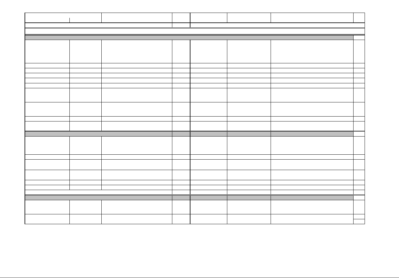
IQ 250/260 Meter App. B: Modbus Map
www.eaton.com IB02601006E MM-17
Description (Note 1) Format Range (Note 6) Units or Resolution Comments
Modbus Address
Hex Decimal #
Reg
read-only
270F - 270F 10000 - 10000 Class ID and card status UINT16 bit-mapped undv-----cccctttt Flags active if bit is set: u=unsupported card; n=card
need configuration; d=card is using default configuration;
v=communication with card is ok
Field: cccc=class of installed card.
Field tttt=type of card. See note 22
1
2710 - 2710 10001 - 10001 Reserved Reserved 1
2711 - 2718 10002 - 10009 Card name ASCII 16 char none ASCII name of the installed card 8
2719 - 2720 10010 - 10017 Serial number ASCII 16 char none Serial Number in ASCII of the installed card 8
2721 - 2722 10018 - 10019 Version ASCII 4 char none Version in ASCII of the hardware of the installed card. 2
2723 - 2746 10020 - 10055 Reserved Reserved 36
2747 - 2748 10056 - 10057 Firmware Version ASCII 4 char none Version of the BOOT firmware of the card, left justified
and padded with spaces. Blank for boards without
embedded firmware.
2
2749 - 274A 10058 - 10059 Firmware Version ASCII 4 char none Version of the RUN firmware of the card, left justified and
padded with spaces. Blank for boards without embedded
firmware.
2
274B - 274E 10060 - 10063 Reserved Reserved 4
Block Size: 64
Read-only
274F - 274F 10064 - 10064 Current speed and format UINT16 bit-mapped -abcde-- fghijklm Bps: a=57600; b=38400; c=19200; d=14400; e=9600
Stop bits 'f': cleared 1 stop bit, set 2 stop bits
Parity: g=even; h=odd; i=none
Data bits: j=8; k=7; l=6; m=5
1
2750 - 2750 10065 - 10065 Reserved UINT16 bit-mapped Reserved 1
2751 - 2751 10066 - 10066 Current protocol UINT16 bit-mapped -------- -----ppp- ppp=protocol
100=DNP3; 010=Ascii Modbus; 001=Rtu Modbus
1
2752 - 2752 10067 - 10067 Current reply delay UINT16 0 to 65535 milliseconds Delay to reply to a Modbus transaction after receiving it. 1
2753 - 2756 10068 - 10071 Reserved Reserved 4
Block Size: 8
read-only
2757 - 2790 10072 - 10129 Data and Control Block for Option Card 1.
Meaning of registers depends on installed card. -
- see below
Register assignments depend on which type of card is in
the slot. See overlays below.
58
Block Size: 66
Option Card 1 Section
Card Identification and Configuration Block (Note 14)
Current Communication Settings for Option Card 1
Data and Control Blocks for Option Card 1
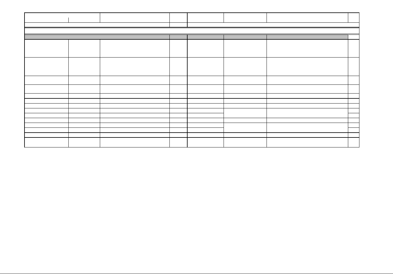
IQ 250/260 Meter App. B: Modbus Map
www.eaton.com IB02601006E MM-18
Description (Note 1) Format Range (Note 6) Units or Resolution Comments
Modbus Address
Hex Decimal #
Reg
read-only except as indicated
2757 - 2757 10072 - 10072 Digital Input States UINT16 bit-mapped -------- 22221111 Two nibble fields: (2222) for input#2 and (1111) for input
#1.
Lsb in each nibble is the current state of the input. Msb
in each nibble is the oldest registered state.
1
2758 - 2758 10073 - 10073 Digital Relay States UINT16 bit-mapped -------- --ab--cd If "a" is 1 then state of Relay#2 is unknown, otherwise
state of Relay#2 is in "c": (1=tripped, 0=released).
If "b" is 1 then state of Relay#1 is unknown, otherwise
state of Relay#1 is in "d": (1=tripped, 0=released).
1
2759 - 2759 10074 - 10074 Turn relay on UINT16 bit-mapped -------- ------21 Writing a 1 in bit N turns relay N+1 ON (this register is
writeable only in privileged session)
1
275A - 275A 10075 - 10075 Turn relay off UINT16 bit-mapped -------- ------21 Writing a 1 in bit N turns relay N+1 OFF (this register is
writeable only in privileged session)
1
275B - 275B 10076 - 10076 Trip/Release delay timer for Relay 1 UINT16 0 to 9999 0.1 sec time to trip or release 1
275C - 275C 10077 - 10077 Trip/Release delay timer for Relay 2 UINT16 0 to 9999 0.1 sec time to trip or release 1
275D - 275E 10078 - 10079 Reserved Reserved 2
275F - 275F 10080 - 10080 Input 1 Accumulator, Scaled UINT16 0 to 9999 1
2760 - 2760 10081 - 10081 Input 2 Accumulator, Scaled UINT16 0 to 9999 1
2761 - 2762 10082 - 10083 Reserved Reserved 2
2763 - 2763 10084 - 10084 Relay 1 Accumulator, Scaled UINT16 0 to 9999 1
2764 - 2764 10085 - 10085 Relay 2 Accumulator, Scaled UINT16 0 to 9999 1
2765 - 2790 10086 - 10129 Reserved Reserved 44
Block Size: 58
resolution is 1, 10, 100, 1000,
10000, or 100000 counts
Disabled accumulators always read 0.
resolution is 1, 10, 100, 1000,
10000, or 100000 counts
Disabled accumulators always read 0.
Expansions for Data and Control Block for Option Card 1
Data and Control Block -- Digital I/O Relay Card Overlay (Note 15)
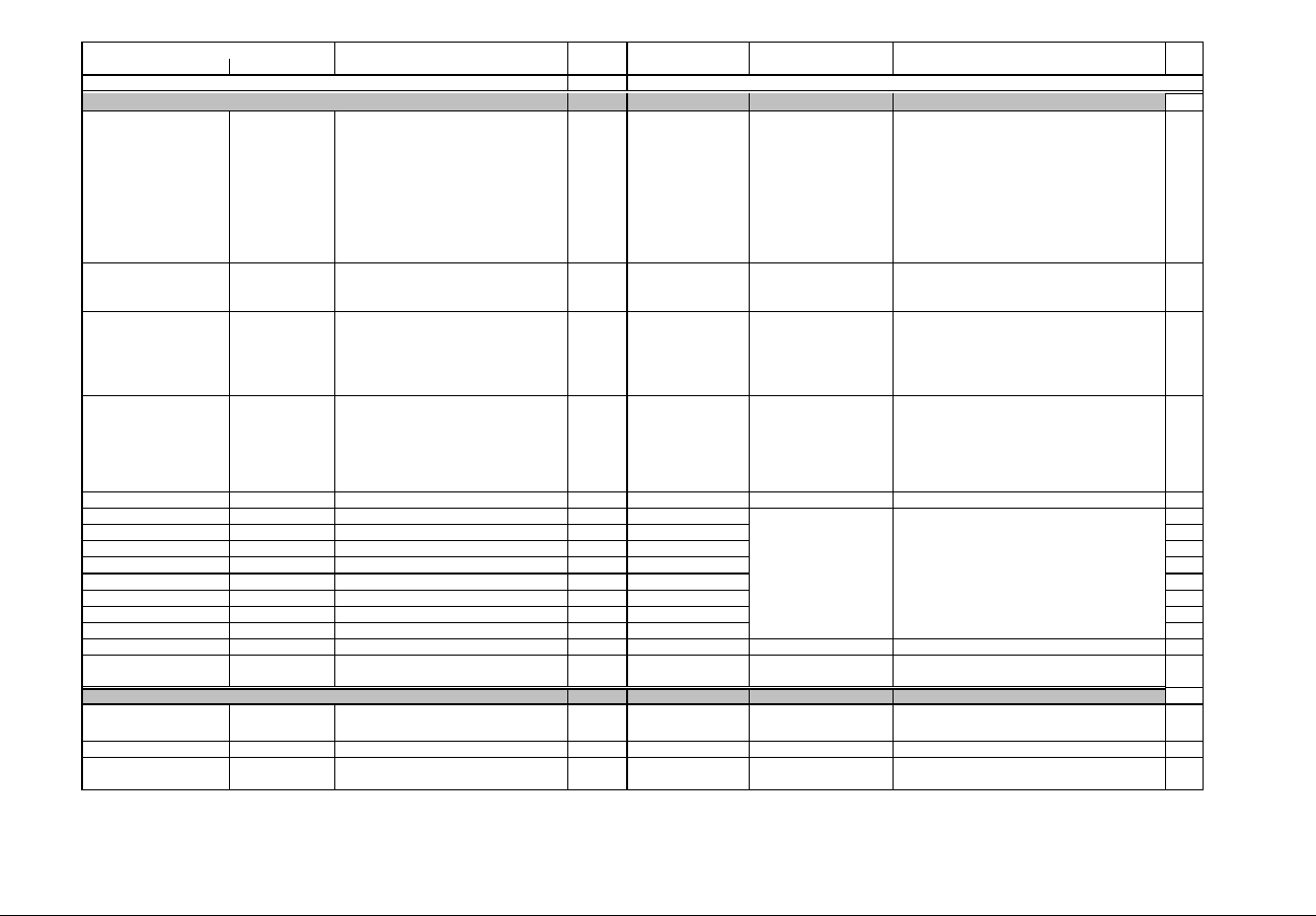
IQ 250/260 Meter App. B: Modbus Map
www.eaton.com IB02601006E MM-19
Description (Note 1) Format Range (Note 6) Units or Resolution Comments
Modbus Address
Hex Decimal #
Reg
read-only except as indicated
2757 - 2757 10072 - 10072 Digital Input States UINT16 bit-mapped dddd cccc bbbb aaaa Nibble "dddd" for input#4, "cccc" for input#3, "bbbb" for
input#2 and "aaaa" for input#1.
Within each field, rightmost bit is the current state
(1=closed, 0=open), and bits at left are the older states
100ms apart. (historical states)
Example:
xxxx xxxx xxxx 0011
Current state of input#1 is closed, before that it was
closed too, before that it was open and the oldest state
known is open.
1
2758 - 2758 10073 - 10073 Digital Output States UINT16 bit-mapped -------- ----4321 One bit for each output. Bit 4 is for output #4, and bit 1 is
for output #1. If a bit is set the output is closed,
otherwise it is opened.
1
2759 - 2759 10074 - 10074 Pulse Output Test Select UINT16 bit-mapped -------- ----4321 Write 1 to a bit to set its corresponding Pulse Output into
test mode. Write 0 to restore it to normal operation. A
privileged session is required to write the bits. Reading
this register reports the mode for each output (1=under
test, 0=normal).
1
275A - 275A 10075 - 10075 Pulse Output Test Power UINT16 bit-mapped ddvvvvvv vvvvvvvv This register is Writeable in privileged session only.
Simulates constant Power for the Pulse Output under
test. Format is same as Kt settings for Pulse Output.
"V" is raw value in Wh/pulse from 0 to 9999.
"dd"=decimal point position: 00=0.XXXX, 01=X.XXX,
10=XX.XX, 11= XXX.X
1
275B - 275E 10076 - 10079 Reserved Reserved 4
275F - 275F 10080 - 10080 Input 1 Accumulator, Scaled UINT16 0 to 9999 1
2760 - 2760 10081 - 10081 Input 2 Accumulator, Scaled UINT16 0 to 9999 1
2761 - 2761 10082 - 10082 Input 3 Accumulator, Scaled UINT16 0 to 9999 1
2762 - 2762 10083 - 10083 Input 4 Accumulator, Scaled UINT16 0 to 9999 1
2763 - 2763 10084 - 10084 Output 1 Accumulator, Scaled UINT16 0 to 9999 1
2764 - 2764 10085 - 10085 Output 2 Accumulator, Scaled UINT16 0 to 9999 1
2765 - 2765 10086 - 10086 Output 3 Accumulator, Scaled UINT16 0 to 9999 1
2766 - 2766 10087 - 10087 Output 4 Accumulator, Scaled UINT16 0 to 9999 1
2767 - 2790 10088 - 10129 Reserved Reserved 42
Block Size: 58
read-only
2757 - 2757 10072 - 10072 Status of card UINT16 bit-mapped ----cf-- -------- Flag fields:
c=calibration not good; f=configuration error
1
2758 - 2790 10073 - 10129 Reserved Reserved 57
Block Size: 58
Data and Control Block -- Digital I/O Pulse Output Card Overlay (Note 15)
resolution is 1, 10, 100, 1000,
10000, or 100000 counts
Disabled accumulators always read 0.
Data and Control Block--Analog Out 0-1mA / Analog Out 4-20mA (Note 15)

IQ 250/260 Meter App. B: Modbus Map
www.eaton.com IB02601006E MM-20
Description (Note 1) Format Range (Note 6) Units or Resolution Comments
Modbus Address
Hex Decimal #
Reg
read-only
2757 - 2757 10072 - 10072 Card and Network Status UINT16 bit-mapped rhp----- sfw-m-ii Flags: r=run mode; h=card is healthy; p=using last good
known programmable settings
Server flags: s=smtp ok; f=ftp ok; w=web server ok;
m=modbus tcp/ip ok.
IP Status ii: 00=IP not valid yet, 01=IP from p.settings;
10=IP from DHCP;11=using last good known IP.
1
2758 - 2758 10073 - 10073 Reserved Reserved 1
2759 - 275B 10074 - 10076 MAC address in use by the network card UINT16 bit-mapped 6 bytes These 3 registers hold the 6 bytes of the card's ethernet
MAC address
3
275C - 275F 10077 - 10080 Current IP Address UINT16 These 4 registers hold the 4 numbers (1 number each
register) that make the IP address used by the card.
4
2760 - 2760 10081 - 10081 Current IP Mask Length UINT16 0 to 32 Number of bits that are set in the IP address mask,
starting from the Msb of the 32 bit word.
Example 24 = 255.255.255.0; a value of 2 would mean
192.0.0.0
1
2761 - 2762 10082 - 10083 Firmware Version ASCII 4 char none Version of the BOOT firmware of the card, left justified
and padded with spaces. Blank for boards without
embedded firmware.
2
2763 - 2764 10084 - 10085 Firmware Version ASCII 4 char none Version of the RUN firmware of the card, left justified and
padded with spaces. Blank for boards without embedded
firmware.
2
2765 - 2790 10086 - 10129 Reserved Reserved for Extended Nw Status 44
Block Size: 58
read-only
2AF7 - 2AF7 11000 - 11000 Class ID and card status UINT16 bit-mapped undv-----cccctttt Flags active if bit is set: u=unsupported card; n=card
need configuration; d=card is using default configuration;
v=communication with card is ok
Field: cccc=class of installed card.
Field tttt=type of card. See note 22
1
2AF8 - 2AF8 11001 - 11001 Reserved Read only 1
2AF9 - 2B00 11002 - 11009 Card name ASCII 16 char none ASCII name of the installed card 8
2B01 - 2B08 11010 - 11017 Serial number ASCII 16 char none Serial Number in ASCII of the installed card 8
2B09 - 2B0A 11018 - 11019 Version ASCII 4 char none Version in ASCII of the hardware of the installed card. 2
2B0B - 2B28 11020 - 11055 Reserved Reserved 36
2B2F - 2B30 11056 - 11057 Firmware Version ASCII 4 char none Version of the BOOT firmware of the card, left justified
and padded with spaces. Blank for boards without
embedded firmware.
2
2B31 - 2B32 11058 - 11059 Firmware Version ASCII 4 char none Version of the RUN firmware of the card, left justified and
padded with spaces. Blank for boards without embedded
firmware.
2
2B33 - 2B36 11060 - 11063 Reserved Reserved 4
Block Size: 64
Data and Control Block -- Network Card Overlay (Note 15)
Option Card 2 Section
Card Identification and Configuration Block (Note 14)
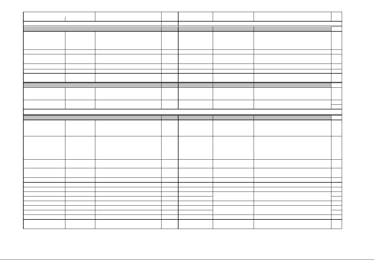
IQ 250/260 Meter App. B: Modbus Map
www.eaton.com IB02601006E MM-21
Description (Note 1) Format Range (Note 6) Units or Resolution Comments
Modbus Address
Hex Decimal #
Reg
Read-only
2B37 - 2B37 11064 - 11064 Current speed and format UINT16 bit-mapped -abcde-- fghijklm Bps: a=57600; b=38400; c=19200; d=14400; e=9600
Stop bits 'f': cleared 1 stop bit, set 2 stop bits
Parity: g=even; h=odd; i=none
Data bits: j=8; k=7; l=6; m=5
1
2B38 - 2B38 11065 - 11065 Reserved UINT16 bit-mapped Reserved 1
2B39 - 2B39 11066 - 11066 Current protocol UINT16 bit-mapped -------- -----ppp- ppp=protocol
100=DNP3; 010=Ascii Modbus; 001=Rtu Modbus
1
2B3A - 2B3A 11067 - 11067 Current reply delay UINT16 0 to 65535 milliseconds Delay to reply a Modbus transaction after receiving it. 1
2B3B - 2B3E 11068 - 11071 Reserved Reserved 4
Block Size: 8
read-only
2B3F - 2B78 11072 - 11129 Data and Control Block for Option Card 2
Meaning of registers depend on installed card. --
see below
Register assignments depend on which type of card is in
the slot. See overlays below.
58
Block Size: 66
read-only except as indicated
2B3F - 2B3F 11072 - 11072 Digital Input States UINT16 bit-mapped -------- 22221111 Two nibble fields: (2222) for input#2 and (1111) for input
#1.
Lsb in each nibble is the current state of the input. Msb
in each nibble is the oldest registered state.
1
2B40 - 2B40 11073 - 11073 Digital Relay States UINT16 bit-mapped -------- --ab--cd If "a" is 1 then state of Relay#2 is unknown, otherwise
state of Relay#2 is in "c": (1=tripped, 0=released).
If "b" is 1 then state of Relay#1 is unknown, otherwise
state of Relay#1 is in "d": (1=tripped, 0=released).
1
2B41 - 2B41 11074 - 11074 Turn relay on UINT16 bit-mapped -------- ------21 Writing a 1 in bit N turns relay N+1 ON (this register is
writeable only in privileged session)
1
2B42 - 2B42 11075 - 11075 Turn relay off UINT16 bit-mapped -------- ------21 Writing a 1 in bit N turns relay N+1 OFF (this register is
writeable only in privileged session)
1
2B43 - 2B43 11076 - 11076 Trip/Release delay timer for Relay 1 UINT16 0 to 9999 0.1 sec time to trip or release 1
2B44 - 2B44 11077 - 11077 Trip/Release delay timer for Relay 2 UINT16 0 to 9999 0.1 sec time to trip or release 1
2B45 - 2B46 11078 - 11079 Reserved Reserved 2
2B47 - 2B47 11080 - 11080 Input 1 Accumulator, Scaled UINT16 0 to 9999 1
2B48 - 2B48 11081 - 11081 Input 2 Accumulator, Scaled UINT16 0 to 9999 1
2B49 - 2B4A 11082 - 11083 Reserved Reserved 2
2B4B - 2B4B 11084 - 11084 Relay 1 Accumulator, Scaled UINT16 0 to 9999 1
2B4C - 2B4C 11085 - 11085 Relay 2 Accumulator, Scaled UINT16 0 to 9999 1
2B4D - 2B78 11086 - 11129 Reserved Reserved 44
Block Size: 58
resolution is 1, 10, 100, 1000,
10000, or 100000 counts
Disabled accumulators always read 0.
Current Communication Settings for Option Card 2
Data and Control Blocks for Option Card 2
Expansions for Data and Control Block for Option Card 2
Data and Control Block -- Digital I/O Relay Card Overlay (Note 15)
resolution is 1, 10, 100, 1000,
10000, or 100000 counts
Disabled accumulators always read 0.
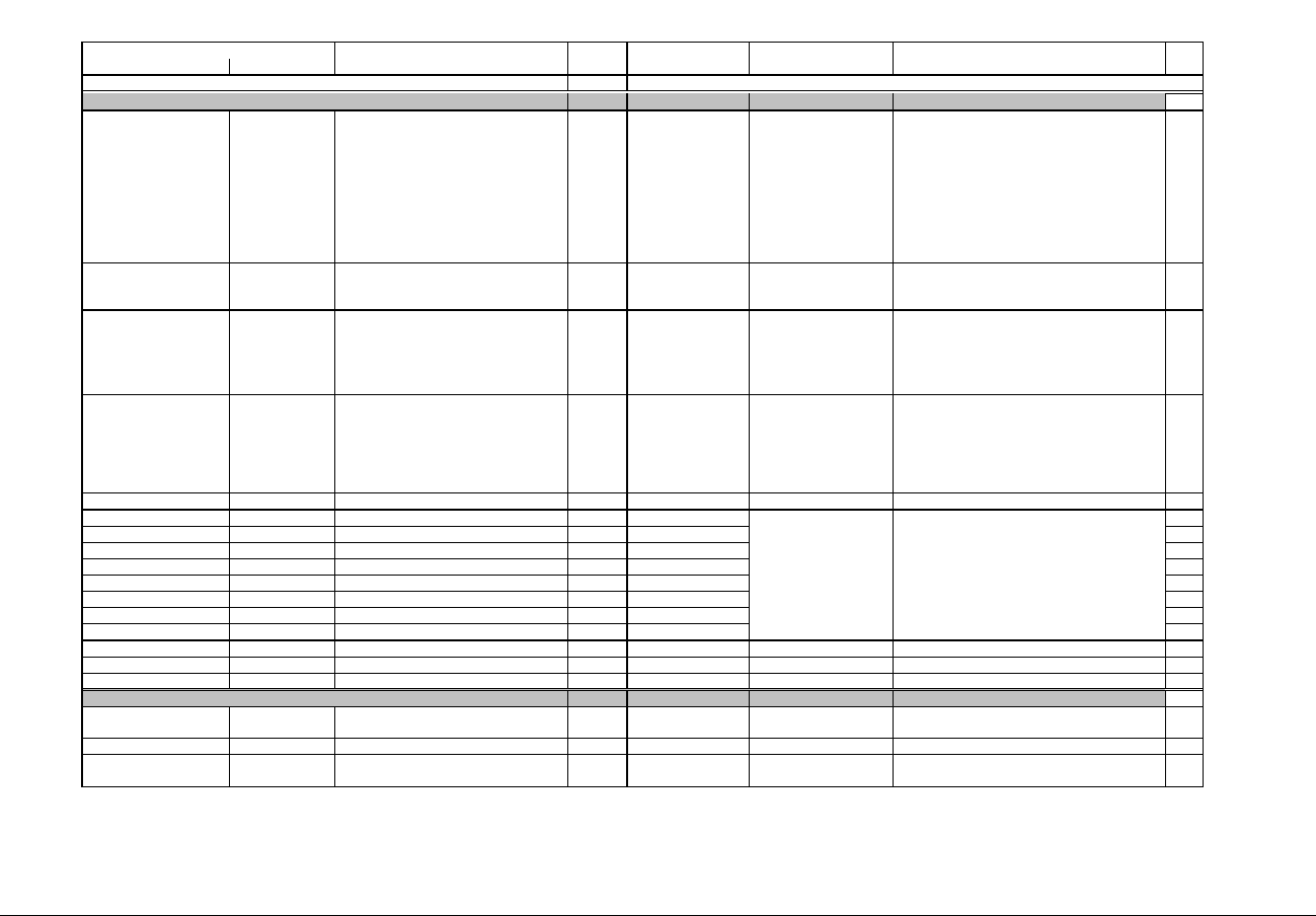
IQ 250/260 Meter App. B: Modbus Map
www.eaton.com IB02601006E MM-22
Description (Note 1) Format Range (Note 6) Units or Resolution Comments
Modbus Address
Hex Decimal #
Reg
read-only except as indicated
2B3F - 2B3F 11072 - 11072 Digital Input States UINT16 bit-mapped dddd cccc bbbb aaaa Nibble "dddd" for input#4, "cccc" for input#3, "bbbb" for
input#2 and "aaaa" for input#1.
Within each field, right most bit is the current state
(1=closed, 0=open), and bits at left are the older states
100ms apart. (historical states)
Example:
xxxx xxxx xxxx 0011
Current state of input#1 is closed, before that it was
closed too, before that it was open and the oldest state
known is open.
1
2B40 - 2B40 11073 - 11073 Digital Output States UINT16 bit-mapped -------- ----4321 One bit for each output. Bit 4 is for output #4, and bit 1 is
for output #1. If a bit is set the output is closed,
otherwise it is opened.
1
2B41 - 2B41 11074 - 11074 Pulse Output Test Select UINT16 bit-mapped -------- ----4321 Write 1 to a bit to set its corresponding Pulse Output into
test mode. Write 0 to restore it to normal operation. A
privileged session is required to write the bits. Reading
this register reports the mode for each output (1=under
test, 0=normal).
1
2B42 - 2B42 11075 - 11075 Pulse Output Test Power UINT16 bit-mapped ddvvvvvv vvvvvvvv This register is Writeable in privileged session only.
Simulates constant Power for the Pulse Output under
test. Format is same as Kt settings for Pulse Output.
"V" is raw value in Wh/pulse from 0 to 9999.
"dd"=decimal point position: 00=0.XXXX, 01=X.XXX,
10=XX.XX, 11= XXX.X
1
2B43 - 2B46 11076 - 11079 Reserved Reserved 4
2B47 - 2B47 11080 - 11080 Input 1 Accumulator, Scaled UINT16 0 to 9999 1
2B48 - 2B48 11081 - 11081 Input 2 Accumulator, Scaled UINT16 0 to 9999 1
2B49 - 2B49 11082 - 11082 Input 3 Accumulator, Scaled UINT16 0 to 9999 1
2B4A - 2B4A 11083 - 11083 Input 4 Accumulator, Scaled UINT16 0 to 9999 1
2B4B - 2B4B 11084 - 11084 Output 1 Accumulator, Scaled UINT16 0 to 9999 1
2B4C - 2B4C 11085 - 11085 Output 2 Accumulator, Scaled UINT16 0 to 9999 1
2B4D - 2B4D 11086 - 11086 Output 3 Accumulator, Scaled UINT16 0 to 9999 1
2B4E - 2B4E 11087 - 11087 Output 4 Accumulator, Scaled UINT16 0 to 9999 1
2B4F - 2B78 11088 - 11129 Reserved Reserved 42
Block Size: 58
read-only
2B3F - 2B3F 11072 - 11072 Status of card UINT16 bit-mapped ----cf-- -------- Flag fields:
c=calibration not good; f=configuration error
1
2B40 - 2B78 11073 - 11129 Reserved UINT16 Reserved 57
Block Size: 58
Data and Control Block -- Digital I/O Pulse Output Card Overlay (Note 15)
resolution is 1, 10, 100, 1000,
10000, or 100000 counts
Disabled accumulators always read 0.
Data and Control Block--Analog Out 0-1mA / Analog Out 4-20mA (Note 15)
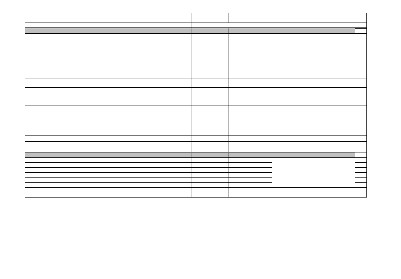
IQ 250/260 Meter App. B: Modbus Map
www.eaton.com IB02601006E MM-23
Description (Note 1) Format Range (Note 6) Units or Resolution Comments
Modbus Address
Hex Decimal #
Reg
read-only
2B3F - 2B3F 11072 - 11072 Card and Network Status UINT16 bit-mapped rhp----- sfw-m-ii Flags: r=run mode; h=card is healthy; p=using last good
known programmable settings
Server flags: s=smtp ok; f=ftp ok; w=web server ok;
m=modbus tcp/ip ok.
IP Status ii: 00=IP not valid yet, 01=IP from p.settings;
10=IP from DHCP;11=using last good known IP.
1
2B40 - 2B40 11073 - 11073 Reserved Reserved 1
2B41 - 2B43 11074 - 11076 MAC address in use by the network card UINT16 bit-mapped 6 bytes These 3 registers hold the 6 bytes of the card's Ethernet
MAC address.
3
2B44 - 2B47 11077 - 11080 Current IP Address UINT16 These 4 registers hold the 4 numbers (1 number each
register) that make the IP address used by the card.
4
2B48 - 2B48 11081 - 11081 Current IP Mask Length UINT16 0 to 32 Number of bits that are set in the IP address mask,
starting from the Msb of the 32 bit word.
Example 24 = 255.255.255.0; a value of 2 would mean
192.0.0.0
1
2B49 - 2B4A 11082 - 11083 Firmware Version ASCII 4 char none Version of the BOOT firmware of the card, left justified
and padded with spaces. Blank for boards without
embedded firmware.
2
2B4B - 2B4C 11084 - 11085 Firmware Version ASCII 4 char none Version of the RUN firmware of the card, left justified and
padded with spaces. Blank for boards without embedded
firmware.
2
2B4D - 2B78 11086 - 11129 Reserved Reserved for Extended Nw Status 44
Block Size: 58
read-only
2EDF - 2EE0 12000 - 12001 Option Card 1, Input 1 Accumulator UINT32 0 to 999999999 number of transitions 2
2EE1 - 2EE6 12002 - 12007 Option Card 1, Inputs 2-4 Accumulators UINT32 0 to 999999999 number of transitions 6
2EE7 - 2EE8 12008 - 12009 Option Card 1, Output or Relay 1 Accumulator UINT32 0 to 999999999 number of transitions 2
2EE9 - 2EEE 12010 - 12015 Option Card 1, Output or Relays 2-4 UINT32 0 to 999999999 number of transitions 6
2EEF - 2EF6 12016 - 12023 Option Card 2 Inputs Accumulators UINT32 0 to 999999999 number of transitions 8
2EF7 - 2EFE 12024 - 12031 Option Card 2 Outputs Accumulators UINT32 0 to 999999999 number of transitions 8
Block Size: 32
Data and Control Block -- Network Card Overlay (Note 15)
Accumulators Block
These are unscaled counts. See option card section
for scaled versions.
Input accumulators count either or both transitions;
output accumulators count both transitions.
Unused accumulators always read 0.

IQ 250/260 Meter App. B: Modbus Map
www.eaton.com IB02601006E MM-24
Description (Note 1) Format Range (Note 6) Units or Resolution Comments
Modbus Address
Hex Decimal #
Reg
write-only
4E1F - 4E1F 20000 - 20000 Reset Max/Min Blocks UINT16 password (Note 5) 1
4E20 - 4E20 20001 - 20001 Reset Energy Accumulators UINT16 password (Note 5) 1
4E21 - 4E21 20002 - 20002 Reset Alarm Log (Note 21) UINT16 password (Note 5) 1
4E22 - 4E22 20003 - 20003 Reset System Log (Note 21) UINT16 password (Note 5) 1
4E23 - 4E23 20004 - 20004 Reset Historical Log 1 (Note 21) UINT16 password (Note 5) 1
4E24 - 4E24 20005 - 20005 Reserved 1
4E25 - 4E25 20006 - 20006 Reserved 1
4E26 - 4E26 20007 - 20007 Reset I/O Change Log (Note 21) UINT16 password (Note 5) 1
4E27 - 4E27 20008 - 20008 Reset Power Quality Log UINT16 password (Note 5) 1
4E28 - 4E28 20009 - 20009 Reset Waveform Capture Log UINT16 password (Note 5) 1
4E29 - 4E2A 20010 - 20011 Reserved Reserved 2
4E2B - 4E2B 20012 - 20012 Reset Option Card 1 Input Accumulators UINT16 password (Note 5) 1
4E2C - 4E2C 20013 - 20013 Reset Option Card 1 Output Accumulators UINT16 password (Note 5) 1
4E2D - 4E2D 20014 - 20014 Reset Option Card 2 Input Accumulators UINT16 password (Note 5) 1
4E2E - 4E2E 20015 - 20015 Reset Option Card 2 Output Accumulators UINT16 password (Note 5) 1
Block Size: 16
conditional write
5207 - 5207 21000 - 21000 Initiate Meter Firmware Reprogramming UINT16 password (Note 5) 1
5208 - 5208 21001 - 21001 Force Meter Restart UINT16 password (Note 5) causes a watchdog reset, always reads 0 1
5209 - 5209 21002 - 21002 Open Privileged Command Session UINT16 password (Note 5) meter will process command registers (this register
through 'Close Privileged Command Session' register
below) for 5 minutes or until the session is closed,
whichever comes first.
1
520A - 520A 21003 - 21003 Initiate Programmable Settings Update UINT16 password (Note 5) meter enters PS update mode 1
520B - 520B 21004 - 21004 Calculate Programmable Settings Checksum
(Note 3)
UINT16 0000 to 9999 meter calculates checksum on RAM copy of PS block 1
520C - 520C 21005 - 21005 Programmable Settings Checksum (Note 3) UINT16 0000 to 9999 read/write checksum register; PS block saved in
nonvolatile memory on write (Note 8)
1
520D - 520D 21006 - 21006 Write New Password (Note 3) UINT16 0000 to 9999 write-only register; always reads zero 1
520E - 520E 21007 - 21007 Terminate Programmable Settings Update (Note
3)
UINT16 any value meter leaves PS update mode via reset 1
520F - 5211 21008 - 21010 Set Meter Clock TSTAMP 1Jan2000 - 31Dec2099 1 sec saved only when 3rd register is written 3
5212 - 5212 21011 - 21011 Reserved Reserved 1
5213 - 5219 21012 - 21018 Reserved Reserved 7
521A - 521A 21019 - 21019 Close Privileged Command Session UINT16 any value ends an open command session 1
Block Size: 20
read/write
658F - 659A 26000 - 26011 Perform a Secure Operation UINT16 encrypted command to read password or change meter
type
12
Block Size: 12
Commands Section (Note 4)
Resets Block (Note 9)
Reply to a reset log command indicates that the
command was accepted but not necessarily that the
reset is finished. Poll log status block to determine this.
Privileged Commands Block
Encryption Block

IQ 250/260 Meter App. B: Modbus Map
www.eaton.com IB02601006E MM-25
Description (Note 1) Format Range (Note 6) Units or Resolution Comments
Modbus Address
Hex Decimal #
Reg
write only in PS update mode
752F - 752F 30000 - 30000 CT multiplier & denominator UINT16 bit-mapped dddddddd mmmmmmmm high byte is denominator (1 or 5, read-only),
low byte is multiplier (1, 10, or 100)
1
7530 - 7530 30001 - 30001 CT numerator UINT16 1 to 9999 none 1
7531 - 7531 30002 - 30002 PT numerator UINT16 1 to 9999 none 1
7532 - 7532 30003 - 30003 PT denominator UINT16 1 to 9999 none 1
7533 - 7533 30004 - 30004 PT multiplier & hookup UINT16 bit-mapped mmmmmmmm mmmmhhhh mm…mm = PT multiplier (1, 10, 100, or 1000)
hhhh = hookup enumeration (0 = 3 element wye[9S], 1 =
delta 2 CTs[5S], 3 = 2.5 element wye[6S])
1
7534 - 7534 30005 - 30005 Averaging Method UINT16 bit-mapped --iiiiii b----sss iiiiii = interval (5,15,30,60)
b = 0-block or 1-rolling
sss = # subintervals (1,2,3,4)
1
7535 - 7535 30006 - 30006 Power & Energy Format UINT16 bit-mapped ppppiinn feee-ddd pppp = power scale (0-unit, 3-kilo, 6-mega, 8-auto)
ii = power digits after decimal point (0-3),
applies only if f=1 and pppp is not auto
nn = number of energy digits (5-8 --> 0-3)
eee = energy scale (0-unit, 3-kilo, 6-mega)
f = decimal point for power
(0=data-dependant placement,
1=fixed placement per ii value)
ddd = energy digits after decimal point (0-6)
See note 10.
1
7536 - 7536 30007 - 30007 Operating Mode Screen Enables UINT16 bit-mapped -------x eeeeeeee eeeeeeee = op mode screen rows on/off, rows top to
bottom are bits low order to high order
x = set to suppress PF on W/VAR/PF screens
1
7537 - 7537 30008 - 30008 Daylight Saving On Rule UINT16 bit-mapped hhhhhwww -dddmmmm 1
7538 - 7538 30009 - 30009 Daylight Saving Off Rule UINT16 bit-mapped hhhhhwww -dddmmmm 1
7539 - 7539 30010 - 30010 Time Zone UTC offset UINT16 bit-mapped z000 0000 hhhh hhmm mm = minutes/15; 00=00, 01=15, 10=30, 11=45
hhhh = hours; -23 to +23
z = Time Zone valid (0=no, 1=yes)
i.e. register=0 indicates that time zone is not set while
register=0x8000 indicates UTC offset = 0 1
753A - 753A 30011 - 30011 Clock Sync Configuration UINT16 bit-mapped 0000 0000 mmm0 0ppe e = enable automatic clock sync (0=no, 1=yes)
pp = port performing synchronization (2-3 = COM3-
COM4)
mmm = sync method (1=NTP, all other values=no sync)
1
Programmable Settings Section
Basic Setups Block
applies only if daylight savings in User Settings Flags =
on; specifies when to make changeover
hhhhh = hour, 0-23
www = week, 1-4 for 1st - 4th, 5 for last
ddd = day of week, 1-7 for Sun - Sat
mmmm = month, 1-12
Example: 2AM on the 4th Sunday of March
hhhhh=2, www=4, ddd=1, mmmm=3

IQ 250/260 Meter App. B: Modbus Map
www.eaton.com IB02601006E MM-26
Description (Note 1) Format Range (Note 6) Units or Resolution Comments
Modbus Address
Hex Decimal #
Reg
753B - 753B 30012 - 30012 Reserved Reserved 1
753C - 753C 30013 - 30013 User Settings 2 UINT16 bit-mapped -------- -------s s = display secondary volts (1=yes, 0=no) 1
753D - 753D 30014 - 30014 DNP Options UINT16 bit-mapped -------- ww-i-vvp p selects primary or secondary values for DNP voltage,
current and power registers
(0=secondary, 1=primary)
vv sets divisor for voltage scaling
(0=1, 1=10, 2=100)
i sets divisor for current scaling
(0=1, 1=10)
ww sets divisor for power scaling in addition to scaling
for Kilo
(0=1, 1=10, 2=100, 3=1000)
Example:
120KV, 500A, 180MW
p=1, vv=2, i=0, and ww=3
voltage reads 1200, current reads 500, watts reads 180
1
753E - 753E 30015 - 30015 User Settings Flags UINT16 bit-mapped vvkgeinn srpdywfa vv = number of digits after decimal point for voltage
display.
0 - For voltage range (0 - 9999V)
1 - For voltage range (100.0kV - 999.9 kV)
2 - For voltage range (10.00kV - 99.99 kV)
3 - For voltage range ( 0kV - 9.999 kV)
This setting is used only when k=1.
k = enable fixed scale for voltage display.
(0=autoscale, 1=unit if vv=0 and kV if vv=1,2,3 )
g = enable alternate full scale bar graph current
(1=on, 0=off)
e = enable ct pt compensation
(0=Disabled, 1=Enabled).
i = fixed scale and format current display
0=normal autoscaled current display
1=always show amps with no decimal places
nn = number of phases for voltage & current screen
(3=ABC, 2=AB, 1=A, 0=ABC)
s = scroll (1=on, 0=off)
r = password for reset in use (1=on, 0=off)
p = password for configuration in use (1=on, 0=off)
d = daylight saving time changes (0=off, 1=on)
y = diagnostic events in system log (1=yes, 0=no)
w = power direction
(0=view as load, 1=view as generator)
f = flip power factor sign (1=yes, 0=no)
a
=
apparent power computation method
1
753F - 753F 30016 - 30016 Full Scale Current (for load % bar graph) UINT16 0 to 9999 none If non-zero and user settings bit g is set, this value
replaces CT numerator in the full scale current
calculation. (See Note 12)
1
7540 - 7547 30017 - 30024 Meter Designation ASCII 16 char none 8
7548 - 7548 30025 - 30025 COM1 setup UINT16 bit-mapped ----dddd -0100110 1
7549 - 7549 30026 - 30026 COM2 setup UINT16 bit-mapped ----dddd -ppp-bbb 1
754A - 754A 30027 - 30027 COM2 address UINT16 1 to 247 none 1
754B - 754B 30028 - 30028 Limit #1 Identifier UINT16 0 to 65535 use Modbus address as the identifier (see notes 7, 11,
12)
1
754C - 754C 30029 - 30029 Limit #1 Out High Setpoint SINT16 -200.0 to +200.0 0.1% of full scale Setpoint for the "above" limit (LM1), see notes 11-12. 1
dddd = reply delay (* 50 msec)
ppp = protocol (1-Modbus RTU, 2-Modbus ASCII, 3-
DNP)
bbb = baud rate (1-9600, 2-19200, 4-38400, 6-57600)

IQ 250/260 Meter App. B: Modbus Map
www.eaton.com IB02601006E MM-27
Description (Note 1) Format Range (Note 6) Units or Resolution Comments
Modbus Address
Hex Decimal #
Reg
754D - 754D 30030 - 30030 Limit #1 In High Threshold SINT16 -200.0 to +200.0 0.1% of full scale Threshold at which "above" limit clears; normally less
than or equal to the "above" setpoint; see notes 11-12.
1
754E - 754E 30031 - 30031 Limit #1 Out Low Setpoint SINT16 -200.0 to +200.0 0.1% of full scale Setpoint for the "below" limit (LM2), see notes 11-12. 1
754F - 754F 30032 - 30032 Limit #1 In Low Threshold SINT16 -200.0 to +200.0 0.1% of full scale Threshold at which "below" limit clears; normally greater
than or equal to the "below" setpoint; see notes 11-12.
1
7550 - 7554 30033 - 30037 Limit #2 SINT16 5
7555 - 7559 30038 - 30042 Limit #3 SINT16 5
755A - 755E 30043 - 30047 Limit #4 SINT16 5
755F - 7563 30048 - 30052 Limit #5 SINT16 5
7564 - 7568 30053 - 30057 Limit #6 SINT16 5
7569 - 756D 30058 - 30062 Limit #7 SINT16 5
756E - 7572 30063 - 30067 Limit #8 SINT16 5
7573 - 7582 30068 - 30083 Reserved Reserved 16
7583 - 75C2 30084 - 30147 Reserved Reserved 64
75C3 - 75C3 30148 - 30148 watts loss due to iron when watts positive UINT16 0 to 99.99 0.01% 1
75C4 - 75C4 30149 - 30149 watts loss due to copper when watts positive UINT16 0 to 99.99 0.01% 1
75C5 - 75C5 30150 - 30150 var loss due to iron when watts positive UINT16 0 to 99.99 0.01% 1
75C6 - 75C6 30151 - 30151 var loss due to copper when watts positive UINT16 0 to 99.99 0.01% 1
75C7 - 75C3 30152 - 30152 watts loss due to iron when watts negative UINT16 0 to 99.99 0.01% 1
75C8 - 75C48 30153 - 30153 watts loss due to copper when watts negative UINT16 0 to 99.99 0.01% 1
75C9 - 75C9 30154 - 30154 var loss due to iron when watts negative UINT16 0 to 99.99 0.01% 1
75CA - 75CA 30155 - 30155 var loss due to copper when watts negative UINT16 0 to 99.99 0.01% 1
75CB - 75CB 30156 - 30156 transformer loss compensation user settings flag UINT16 bit-mapped -------- ----cfwv c - 0 disable compensation for losses due to copper,
1 enable compensaion for losses due to copper
f - 0 disable compensation for losses due to iron,
1 enable compensaion for losses due to iron
w - 0 add watt compensation,
1 subtract watt compensation
v - 0 add var compensation,
1 subtract var compensation
1
75CC - 75E5 30157 - 30182 Reserved Reserved 26
75E6 - 75E6 30183 - 30183 Programmable Settings Update Counter UINT16 0-65535 Increments each time programmable settings are
changed; occurs when new checksum is calculated.
1
75E8 - 7607 30184 - 30215 Non-voltaile registers for use by system
integrators
SINT16 32
7608 - 7626 30216 - 30247 Reserved for Software Use Reserved 32
7627 - 7627 30248 - 30248 A phase PT compensation @ 69V (% error) SINT16 -15 to 15 0.01% 1
7628 - 7628 30249 - 30249 A phase PT compensation @ 120V (% error) SINT16 -15 to 15 0.01% 1
7629 - 7629 30250 - 30250 A phase PT compensation @ 230V (% error) SINT16 -15 to 15 0.01% 1
762A - 762A 30251 - 30251 A phase PT compensation @ 480V (% error) SINT16 -15 to 15 0.01% 1
762B - 762B 30252 - 30255 B phase PT compensation @ 69V, 120V, 230V,
480V (% error)
SINT16 -15 to 15 0.01% 4
762F - 762F 30256 - 30259 C phase PT compensation @ 69V, 120V, 230V,
480V (% error)
SINT16 -15 to 15 0.01% 4
same as Limit #1 same as Limit #1 same as Limit #1

IQ 250/260 Meter App. B: Modbus Map
www.eaton.com IB02601006E MM-28
Description (Note 1) Format Range (Note 6) Units or Resolution Comments
Modbus Address
Hex Decimal #
Reg
7633 - 7633 30260 - 30260 A phase CT compensation @ c1 (% error) SINT16 -15 to 15 0.01% 1
7634 - 7634 30261 - 30261 A phase CT compensation @ c2 (% error) SINT16 -15 to 15 0.01% 1
7635 - 7635 30262 - 30262 A phase CT compensation @ c3 (% error) SINT16 -15 to 15 0.01% 1
7636 - 7636 30263 - 30263 A phase CT compensation @ c4 (% error) SINT16 -15 to 15 0.01% 1
7637 - 7637 30264 - 30267 B phase CT compensation @ c1, c2, c3, c4 (%
error)
SINT16 -15 to 15 0.01% 4
763B - 763E 30268 - 30271 C phase CT compensation @ c1, c2, c3, c4 (%
error)
SINT16 -15 to 15 0.01% 4
763F - 7642 30272 - 30275 A phase PF compensation @ c1, c2, c3, c4 SINT16 -50 to 50 4
7643 - 7646 30276 - 30279 B phase PF compensation @ c1, c2, c3, c4 SINT16 -50 to 50 4
7647 - 764A 30280 - 30283 C phase PF compensation @ c1, c2, c3, c4 SINT16 -50 to 50 4
Block Size: 284
write only in PS update mode
7917 - 7917 31000 - 31000 Historical Log #1 Sizes UINT16 bit-mapped eeeeeeee ssssssss high byte is number of registers to log in each record (0-
117),
low byte is number of flash sectors for the log (see note
19)
0 in either byte disables the log
1
7918 - 7918 31001 - 31001 Historical Log #1 Interval UINT16 bit-mapped 00000000 hgfedcba only 1 bit set: a=1 min, b=3 min, c=5 min, d=10 min,
e=15 min, f=30 min, g=60 min, h=EOI pulse
1
7919 - 7919 31002 - 31002 Historical Log #1, Register #1 Identifier UINT16 0 to 65535 use Modbus address as the identifier (see note 7) 1
791A - 798D 31003 - 31118 Historical Log #1, Register #2 - #117 Identifiers UINT16 0 to 65535 same as Register #1 Identifier 116
798E - 79D6 31119 - 31191 Historical Log #1 Software Buffer Reserved for software use. 73
79D7 - 7A96 31192 - 31383 Reserved 192
7A97 - 7B56 31384 - 31575 Reserved 192
7B57 - 7B57 31576 - 31607 Reserved
.
.
1
7B58 - 7B58 31577 - 31577 Reserved
7B59 - 7B59 31578 - 31578 Reserved 1
7B5A - 7B5A 31579 - 31579 Reserved .
.
1
7B5B - 7B5B 31580 - 31580 Reserved Reserved 1
7B5C - 7B5C 31581 - 31581 Channel A Voltage Surge Threshold UINT16 0 to 3276.7 0.1% of full scale 1
7B5D - 7B5D 31582 - 31582 Channel A Current Surge Threshold UINT16 0 to 3276.7 0.1% of full scale 1
7B5E - 7B5E 31583 - 31583 Channel A Voltage Sag Threshold UINT16 0 to 3276.7 0.1% of full scale 1
7B5F - 7B61 31584 - 31586 Reserved Reserved 3
7B62 - 7B67 31587 - 31592 Channel B Surge & Sag Thresholds 6
7B68 - 7B6D 31593 - 31598 Channel C Surge & Sag Thresholds 6
7B6E - 7B76 31599 - 31607 Reserved Reserved 9
Block Size: 608
.
.
.
.
Thresholds are % of full scale, see note 12
same as Channel A
same as Channel A
For Class 10 unit
c1=0.25A
c2=0.5A
c3=1A
c4=5A
For Class 2 unit
c1=0.05A
c2=0.1A
c3=0.2A
c4=1A
Log Setups Block
IQ 250/260 Meter App. B: Modbus Map
www.eaton.com IB02601006E MM-29
Description (Note 1) Format Range (Note 6) Units or Resolution Comments
Modbus Address
Hex Decimal #
Reg
write only in PS update mode
7CFF - 7CFF 32000 - 32000 Class ID of the Option Card 1 Settings UINT16 bit-mapped -------- cccctttt Which class (cccc) and type(tttt) of card the Option
Settings for Card 1 apply to. See note 22.
1
7D00 - 7D3E 32001 - 32063 Settings for Option Card 1, First Overlay -- see
below
63
7D3F - 7F3E 32064 - 32575 Settings for Option Card 1, Second Overlay --
see below
512
Block Size: 576
First Overlay write only in PS update mode
7D00 - 7D00 32001 - 32001 Slave address UINT16 1~247 (for Modbus)
1~65534 (for DNP)
none Slave address of the unit. The communication capable
card is always a master.
Set to 0 when an analog board is installed.
1
7D01 - 7D01 32002 - 32002 Speed and format UINT16 bit-mapped -abcde--fghijklm Bps: a=57600; b=38400; c=19200; d=14400; e=9600
Stop bits 'f': cleared 1 stop bit, set 2 stop bits
Parity: g=even; h=odd; i=none
Data bits: j=8; k=7; l=6; m=5
Set to 0 when an analog board is installed.
1
7D02 - 7D02 32003 - 32003 Reserved Reserved 1
7D03 - 7D03 32004 - 32004 Protocol UINT16 bit-mapped -------- -----ppp- ppp= 100 =DNP3; 010=Ascii Modbus; 001=Rtu Modbus
Set to 0 when an analog board is installed.
1
7D04 - 7D04 32005 - 32005 Reply delay UINT16 0 to 65535 milliseconds Delay to reply to a Modbus transaction after receiving it.
Set to 0 when an analog board is installed
1
7D05 - 7D3E 32006 - 32063 Reserved Reserved 58
Block Size: 63
First Overlay write only in PS update mode
7D00 - 7D00 32001 - 32001 Input#1 - 2 bindings & logging enables UINT16 bit-mapped -------- 2222 1111 One nibble for each input.
Assuming "abcc" as the bits in each nibble:
"a": select this input for EOI (End Of Interval)pulse
sensing.
"b": log this input when pulse is detected
"cc": Input event trigger mode - Contact sensing method;
00 = none; 01 = open to close; 10 = close to open; 11 =
any change.
Every input has an associated internal accumulator (See
input Accumulator Scaling), which is incremented every
time the input changes according with the trigger mode
crieteria “cc”
1
7D01 - 7D01 32002 - 32002 Relay #1 Delay to Operate UINT16 0.1 second units Delay to operate the relay since request. 1
7D02 - 7D02 32003 - 32003 Relay #1 Delay to Release UINT16 0.1 second units Delay to release the relay since request. 1
7D03 - 7D08 32004 - 32009 Reserved UINT16 Set to 0. 6
7D09 - 7D09 32010 - 32010 Relay #2 Delay to Operate UINT16 0.1 second units Delay to operate the relay since request. 1
7D0A - 7D0A 32011 - 32011 Relay #2 Delay to Release UINT16 0.1 second units Delay to release the relay since request. 1
7D0B - 7D20 32012 - 32033 Reserved UINT16 Set to 0. 22
7D21 - 7D21 32034 - 32034 Input Accumulators Scaling UINT16 bit-mapped -------- 22221111 1
Overlays for Option Card 1 Programmable Settings
Settings Registers for any communication capable card, including network and analog cards
Settings Registers for Digital I/O Relay Card
4 bits per input or output accumulator
Programmable Settings for Option Card 1
Option Card 1 Setups Block
Register assignments depend on which type of card is in the slot. See overlays below.
Register assignments depend on which type of card is in the slot. See overlays below.

IQ 250/260 Meter App. B: Modbus Map
www.eaton.com IB02601006E MM-30
Description (Note 1) Format Range (Note 6) Units or Resolution Comments
Modbus Address
Hex Decimal #
Reg
7D22 - 7D22 32035 - 32035 Relay Accumulators Scaling UINT16 bit-mapped -------- 22221111 1
7D23 - 7D23 33036 - 33036 Fast pulse input selector UINT16 bit-mapped p------- -----nnn When value 'nnn' is non-zero, it determines which of the
card inputs will be a fast pulse detection input.
The polarity bit 'P' tells the event to be detected: 1=open-
to-close; 0=close-to-open. There is no “any-change”
detection mode
1
7D24 - 7D3E 32037 - 32063 Reserved Set to 0. 27
Block Size: 63
First Overlay write only in PS update mode
7D00 - 7D00 32001 - 32001 Input#1 - 4 bindings & logging enables UINT16 bit-mapped 44443333 22221111 One nibble for each input.
Assuming "abcc" as the bits in each nibble:
"a": select this input for EOI (End Of Interval)pulse
sensing.
"b": log this input when pulse is detected
"cc": Input event trigger mode - Contact sensing method;
00 = none; 01 = open to close; 10 = close to open; 11 =
any change.
Every input has an associated internal accumulator (See
input Accumulator Scaling), which is incremented every
time the input changes according with the trigger mode
crieteria “cc”
1
7D01 - 7D01 32002 - 32002 Source for Pulse Ouput#1 UINT16 enumeration -----ppp ----vvvv "ppp" (Phase) : 000 = none, 001 = Phase A, 010 =
Phase B, 011 = Phase C, 100 = All Phases, 101 = Pulse
from EOI(End Of Interval).
"vvvv"(Value) :
0000= none,
0001 = Wh,
0010 = +Wh,
0011 = -Wh,
0100= Varh,
0101 = +Varh,
0110 = -Varh,
0111 = VAh,
1000= Received Wh,
1001= Delivered Wh,
1010= Inductive Varh,
1011 = Capacitive Varh
1
The nibble informs what should be the scaling of the
accumulator 0=no-scaling, 1=0.1, 2=0.01, 3= 1m,
4=0.1m, 5=0.01m, 6=1u, 7=0.1u; the value 15 disable
the accumulator.
Example: suppose that the internal input accumulator #1
is 12345, and its corresponding scaling setting is “0011”
(3 decimal). Then, the accumulator will be read as:
Scaling 3, means 1m or 0.001.
Scaled accumulator = 12345 * 0.001 = 12 (Twelve).
Settings Registers for Digital I/O Pulse Output Card
IQ 250/260 Meter App. B: Modbus Map
www.eaton.com IB02601006E MM-31
Description (Note 1) Format Range (Note 6) Units or Resolution Comments
Modbus Address
Hex Decimal #
Reg
7D02 - 7D02 32003 - 32003 Kt [Wh/pulse] factor for Pulse Output#1 UINT16 bit-mapped ddVVVVVV VVVVVVVV "V…V" = not scaled energy value per pulse, from 0 to
9999.
"dd"= decimal point position: 00=0.XXXX, 01=X.XXX,
10=XX.XX, 11= X.XXX.
1
7D03 - 7D04 32004 - 32005 Output#2 Assignment and Kt UINT16 2
7D05 - 7D06 32006 - 32007 Output#3 Assignment and Kt UINT16 2
7D07 - 7D08 32008 - 32009 Output#4 Assignment and Kt UINT16 2
7D09 - 7D09 32010 - 32010 Input Accumulators Scaling UINT16 bit-mapped 44443333 22221111 1
7D0A - 7D0A 32011 - 32011 Output Accumulators Scaling UINT16 bit-mapped 44443333 22221111 1
7D0B - 7D0B 32012 - 32012 Fast pulse input selector UINT16 bit-mapped p------- -----nnn When value 'nnn' is non-zero, it determines which of the
card inputs will be a fast pulse detection input.
The polarity bit 'P' tells the event to be detected: 1=open-
to-close; 0=close-to-open. There is no “any-change”
detection mode.
1
7D0C - 7D3E 32013 - 32063 Reserved Reserved 51
Block Size: 63
Second Overlay write only in PS update mode
7D3F - 7D46 32064 - 32071 Input#1 Label ASCII 16 char 8
7D47 - 7D4E 32072 - 32079 Input#1 Low State Name ASCII 16 char 8
7D4F - 7D56 32080 - 32087 Input#1 High State Name ASCII 16 char 8
7D57 - 7D6E 32088 - 32111 Input#2 Label and State Names 24
7D6F - 7D9E 32112 - 32159 Reserved Reserved 48
7D9F - 7DA6 32160 - 32167 Relay#1 Label ASCII 16 char 8
7DA7 - 7DAE 32168 - 32175 Relay#1 Open State Name ASCII 16 char 8
7DAF - 7DB6 32176 - 32183 Relay#1 Closed State Name ASCII 16 char 8
7DB7 - 7DCE 32184 - 32207 Relay#2 Label and State Names 24
7DCF - 7DFE 32208 - 32255 Reserved Reserved 48
7DFF - 7E06 32256 - 32263 Input#1 Accumulator Label ASCII 16 char 8
7E07 - 7E0E 32264 - 32271 Input#2 Accumulator Label ASCII 16 char 8
7E0F - 7E1E 32272 - 32287 Reserved Reserved 16
7E1F - 7E1F 32288 - 32288 Input#1 Accumulator Kt UINT16 bit-mapped ddVVVVVV VVVVVVVV 1
7E20 - 7E20 32289 - 32289 Input#2 Accumulator Kt UINT16 bit-mapped ddVVVVVV VVVVVVVV 1
7E21 - 7F3E 32290 - 32575 Reserved Reserved 286
Block Size: 512
Second Overlay write only in PS update mode
7D3F - 7D46 32064 - 32071 Input#1 Label ASCII 16 char 8
7D47 - 7D4E 32072 - 32079 Input#1 Low State Name ASCII 16 char 8
7D4F - 7D56 32080 - 32087 Input#1 High State Name ASCII 16 char 8
7D57 - 7D6E 32088 - 32111 Input#2 Label and State Names 24
7D6F - 7D86 32112 - 32135 Input#3 Label and State Names 24
7D87 - 7D9E 32136 - 32159 Input#4 Label and State Names 24same as Input#1
see Relay Card above
Settings Registers for Digital I/O Relay Card
same as Input#1
same as Relay#1
KT power factor for the Pulse Output
"V" is raw power value in Wh/pulse from 0 to 9999.
"dd"=decimal point position: 00=0.XXXX, 01=X.XXX,
10=XX.XX, 11= X.XXX.
Settings Registers for Digital I/O Pulse Output Card
same as Input#1
same as Input#1
same as Output #1
same as Output #1
same as Output #1
IQ 250/260 Meter App. B: Modbus Map
www.eaton.com IB02601006E MM-32
Description (Note 1) Format Range (Note 6) Units or Resolution Comments
Modbus Address
Hex Decimal #
Reg
7D9F - 7DA6 32160 - 32167 Output#1 Label ASCII 16 char 8
7DA7 - 7DAE 32168 - 32175 Output#1 Open State Name ASCII 16 char 8
7DAF - 7DB6 32176 - 32183 Output#1 Closed State Name ASCII 16 char 8
7DB7 - 7DCE 32184 - 32207 Output#2 Label and State Names 24
7DCF - 7DE6 32208 - 32231 Output#3 Label and State Names 24
7DE7 - 7DFE 32232 - 32255 Output#4 Label and State Names 24
7DFF - 7E06 32256 - 32263 Input#1 Accumulator Label ASCII 16 char 8
7E07 - 7E0E 32264 - 32271 Input#2 Accumulator Label ASCII 16 char 8
7E0F - 7E16 32272 - 32279 Input#3 Accumulator Label ASCII 16 char 8
7E17 - 7E1E 32280 - 32287 Input#4 Accumulator Label ASCII 16 char 8
7E1F - 7E1F 32288 - 32288 Input#1 Accumulator Kt UINT16 bit-mapped ddVVVVVV VVVVVVVV 1
7E20 - 7E20 32289 - 32289 Input#2 Accumulator Kt UINT16 bit-mapped ddVVVVVV VVVVVVVV 1
7E21 - 7E21 32290 - 32290 Input#3 Accumulator Kt UINT16 bit-mapped ddVVVVVV VVVVVVVV 1
7E22 - 7E22 32291 - 32291 Input#4 Accumulator Kt UINT16 bit-mapped ddVVVVVV VVVVVVVV 1
7E23 - 7F3E 32292 - 32575 Reserved Reserved 284
Block Size: 512
Second Overlay write only in PS update mode
7D3F - 7D3F 32064 - 32064 Update rate UINT16 0 to 65535 milliseconds Fixed -- see specifications. 1
7D40 - 7D40 32065 - 32065 Channel direction - 1mA Card only! UINT16 bit-mapped -------- ----4321 Full range output for 0-1mA card only: A bit set(1) means
full range (-1mA to +1mA); a bit cleared(0) means source
only (0mA to +1mA).
1
7D41 - 7D41 32066 - 32066 Format parameter for output #1 UINT16 bit-mapped -------- ---f suwb Format of the polled register:f=float 32; s=signed 32 bit
int; u=unsigned 32 bit int; w=signed 16 bit int;
b=unsigned 16 bit int.
1
7D42 - 7D42 32067 - 32067 Source register for Output#1 UINT16 0 to 65535 This register should be programmed with the address of
the register whose value is to be used for current output.
In different words, the current level output of analog
board will follow the value of the register addressed here.
1
7D43 - 7D44 32068 - 32069 High value of source register for output#1 Value read from the source register at which High
nominal current will be output. Example: for the 4-20mA
card, if this register is programmed with 750, then the
current output will be 20mA when the value read from the
source register is 750.
2
7D45 - 7D46 32070 - 32071 Low value of source register for output#1 Value read from the source register at which Low
nominal current will be output. Example: for the 4-20mA
card, if this register is programmed with 0, then the
current output will be 4mA when the value read from the
source register is 0.
2
7D47 - 7D4C 32072 - 32077 Analog output#2 format, register, max & min 6Same as analog output#1
same as Output#1
same as Output#1
same as Output#1
KT power factor for the accumulator input
"V" is raw power value in Wh/pulse from 0 to 9999.
"dd"=decimal point position: 00=0.XXXX, 01=X.XXX,
10=XX.XX, 11= X.XXX.
Settings Registers for Analog Out 0-1mA / Analog Out 4-20mA Cards
Depends on the format parameter
Depends on the format parameter

IQ 250/260 Meter App. B: Modbus Map
www.eaton.com IB02601006E MM-33
Description (Note 1) Format Range (Note 6) Units or Resolution Comments
Modbus Address
Hex Decimal #
Reg
7D4D - 7D52 32078 - 32083 Analog output#3 format, register, max & min 6
7D53 - 7D58 32084 - 32089 Analog output#4 format, register, max & min 6
7D59 - 7F3E 32090 - 32575 Reserved Reserved 486
Block Size: 512
Second Overlay write only in PS update mode
7D3F - 7D3F 32064 - 32064 General Options bit-mapped -------- ---s cwme Servers enable(1) or disable(0) flags:
s=Modbus_TCP_server; c=Modbus_TCP_client; w=Web
server ; m=HTTP Modbus RTU for diagnostics.
Sleep enabled e=0; sleep disabled e=1.
1
7D40 - 7D40 32065 - 32065 DHCP enable bit-mapped -------- -------d DHCP: d=1 enabled, d=0 disabled (user must provide IP
configuration).
1
7D41 - 7D48 32066 - 32073 Host name label ASCII 16 bytes (8 registers) 8
7D49 - 7D4C 32074 - 32077 IP card network address UINT16 0 to 255 (IPv4) These 4 registers hold the 4 numbers (1 number each
register) that make the IP address used by the card.
4
7D4D - 7D4D 32078 - 32078 IP network address mask length UINT16 0 to 32 Number of bits that are set in the IP address mask,
starting from the Msb of the 32 bit word.
Example 24 = 255.255.255.0; a value of 2 would mean
192.0.0.0
1
7D4E - 7D51 32079 - 32082 IP card network gateway address UINT16 0 to 255 (IPv4) These 4 registers hold the 4 numbers that make the IP
gateway address on network.
4
7D52 - 7D55 32083 - 32086 IP card network DNS #1 address UINT16 0 to 255 (IPv4) IP address of the DNS#1 on the network. 4
7D56 - 7D59 32087 - 32090 IP card network DNS #2 address UINT16 0 to 255 (IPv4) IP address of the DNS#2 on the network. 4
7D5A - 7E62 32091 - 32355 Reserved Write this with 0 to keep future compatibility. 265
7E63 - 7E63 32356 - 32356 FTP Client Flags bit-mapped -------- -----u-e General FTP flags:
u: 0=FTP remote address is an URL address; 1=FTP
remote address is an IP address.
e: 0=FTP disabled; 1=Enabled.
1
7E64 - 7E64 32357 - 32357 Reserved Set to 0 1
7E65 - 7E84 32358 - 32389 FTP remote server address ASCII or
UINT16
The type of the data in these registers depend on bit 'u'
in the FTP Client Flags register.
IP address (4 numbers) or URL (64-characters) of the
FTP server
32
7E85 - 7E85 32390 - 32390 FTP remote port UINT16 IP port of the remote FTP server 1
7E86 - 7EC5 32391 - 32454 FTP remote directory ASCII 128 characters Remote directory where the files to be retrieved are. 64
7EC6 - 7ED5 32455 - 32470 FTP remote username ASCII 32 characters Username to access remote FTP 16
7ED6 - 7EE5 32471 - 32485 FTP remote password ASCII 32 characters Password to for previous username account. 16
7EE6 - 7F3E 32486 - 32575 Reserved Set to 0 89
Block Size: 512
Same as analog output#1
Same as analog output#1
Settings Registers for Network Cards
IQ 250/260 Meter App. B: Modbus Map
www.eaton.com IB02601006E MM-34
Description (Note 1) Format Range (Note 6) Units or Resolution Comments
Modbus Address
Hex Decimal #
Reg
write only in PS update mode
80E7 - 80E7 33000 - 33000 Class ID of the Option Card 2 Settings UINT16 bit-mapped -------- cccctttt Which class (cccc) and type(tttt) of card the Option
Settings for Card 2 apply to. See note 22
1
80E8 - 8126 33001 - 33063 Settings for Option Card 2, First Overlay -- see
below
63
8127 - 8326 33064 - 33575 Settings for Option Card 2, Second Overlay --
see below
512
Block Size: 576
First Overlay write only in PS update mode
80E8 - 80E8 33001 - 33001 Slave address UINT16 1~247 (for Modbus)
1~65534 (for DNP)
none Slave address of the unit. The communication capable
card is always a master.
Set to 0 when an analog board is installed.
1
80E9 - 80E9 33002 - 33002 Speed and format UINT16 bit-mapped -abcde--fghijklm Bps: a=57600; b=38400; c=19200; d=14400; e=9600
Stop bits 'f': cleared 1 stop bit, set 2 stop bits
Parity: g=even; h=odd; i=none
Data bits: j=8; k=7; l=6; m=5
Set to 0 when an analog board is installed.
1
80EA - 80EA 33003 - 33003 Reserved UINT16 bit-mapped Reserved 1
80EB - 80EB 33004 - 33004 Protocol UINT16 bit-mapped -------- -----ppp- ppp= 100 =DNP3; 010=Ascii Modbus; 001=Rtu Modbus
Set to 0 when an analog board is installed.
1
80EC - 80EC 33005 - 33005 Reply delay UINT16 0 to 65535 milliseconds Delay to reply to a Modbus transaction after receiving it.
Set to 0 when an analog board is installed
1
80ED - 8126 33006 - 33063 Reserved Reserved 58
Block Size: 63
Overlays for Option Card 2 Programmable Settings
Settings Registers for any communication capable card, including network and analog cards
Programmable Settings for Option Card 2
Option Card 2 Setups Block
Register assignments depend on which type of card is in the slot. See overlays below.
Register assignments depend on which type of card is in the slot. See overlays below.
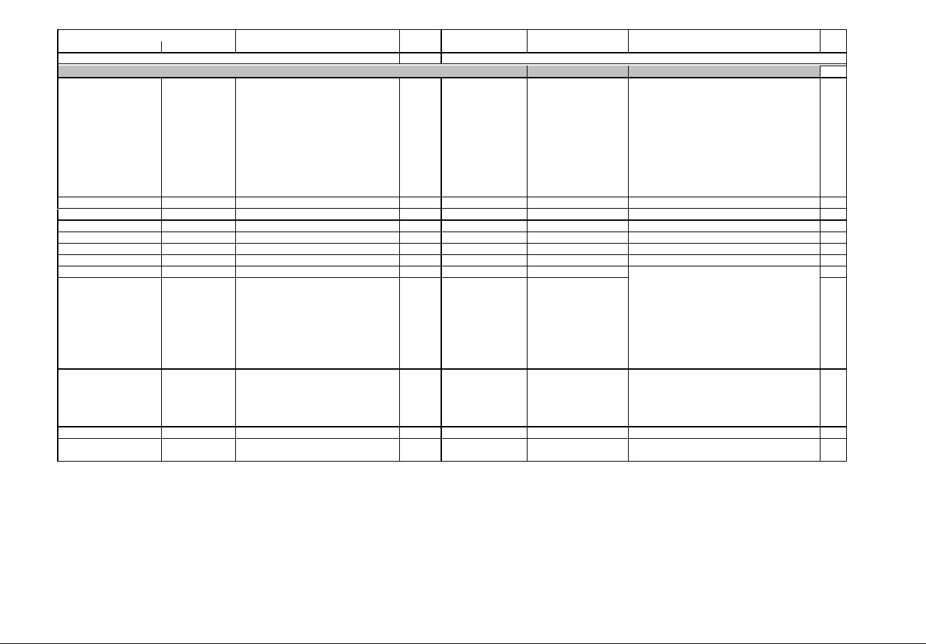
IQ 250/260 Meter App. B: Modbus Map
www.eaton.com IB02601006E MM-35
Description (Note 1) Format Range (Note 6) Units or Resolution Comments
Modbus Address
Hex Decimal #
Reg
First Overlay write only in PS update mode
80E8 - 80E8 33001 - 33001 Input#1 - 2 bindings & logging enables UINT16 bit-mapped -------- 2222 1111 One nibble for each input.
Assuming "abcc" as the bits in each nibble:
"a": select this input for EOI (End Of Interval)pulse
sensing.
"b": log this input when pulse is detected
"cc": Input event trigger mode - Contact sensing method;
00 = none; 01 = open to close; 10 = close to open; 11 =
any change.
Every input has an associated internal accumulator (See
input Accumulator Scaling), which is incremented every
time the input changes according with the trigger mode
crieteria “cc”
1
80E9 - 80E9 33002 - 33002 Relay #1 Delay to Operate UINT16 0.1 second units Delay to operate the relay since request. 1
80EA - 80EA 33003 - 33003 Relay #1 Delay to Release UINT16 0.1 second units Delay to release the relay since request. 1
80EB - 80F0 33004 - 33009 Reserved UINT16 Set to 0. 6
80F1 - 80F1 33010 - 33010 Relay #2 Delay to Operate UINT16 0.1 second units Delay to operate the relay since request. 1
80F2 - 80F2 33011 - 33011 Relay #2 Delay to Release UINT16 0.1 second units Delay to release the relay since request. 1
80F3 - 8108 33012 - 33033 Reserved UINT16 Set to 0. 22
8109 - 8109 33034 - 33034 Input Accumulators Scaling UINT16 bit-mapped -------- 22221111 1
810A - 810A 33035 - 33035 Relay Accumulators Scaling UINT16 bit-mapped -------- 22221111 1
810B - 810B 33036 - 33036 Fast pulse input selector UINT16 bit-mapped p------- -----nnn When value 'nnn' is non-zero, it determines which of the
card inputs will be a fast pulse detection input.
The polarity bit 'P' tells the event to be detected: 1=open-
to-close; 0=close-to-open. There is no “any-change”
detection mode.
1
810C - 8126 33037 - 33063 Reserved Reserved 27
Block Size: 63
Settings Registers for Digital I/O Relay Card
4 bits per input or output accumulator
The nibble informs what should be the scaling of the
accumulator 0=no-scaling, 1=0.1, 2=0.01, 3= 1m,
4=0.1m, 5=0.01m, 6=1u, 7=0.1u; the value 15 disable
the accumulator.
Example: suppose that the internal input accumulator #1
is 12345, and its corresponding scaling setting is “0011”
(3 decimal). Then, the accumulator will be read as:
Scaling 3, means 1m or 0.001.
Scaled accumulator = 12345 * 0.001 = 12 (Twelve).

IQ 250/260 Meter App. B: Modbus Map
www.eaton.com IB02601006E MM-36
Description (Note 1) Format Range (Note 6) Units or Resolution Comments
Modbus Address
Hex Decimal #
Reg
First Overlay write only in PS update mode
80E8 - 80E8 33001 - 33001 Input#1 - 4 bindings & logging enables UINT16 bit-mapped 44443333 22221111 One nibble for each input.
Assuming "abcc" as the bits in each nibble:
"a": select this input for EOI (End Of Interval)pulse
sensing.
"b": log this input when pulse is detected
"cc": Input event trigger mode - Contact sensing method;
00 = none; 01 = open to close; 10 = close to open; 11 =
any change.
Every input has an associated internal accumulator (See
input Accumulator Scaling), which is incremented every
time the input changes according with the trigger mode
crieteria “cc”
1
80E9 - 80E9 33002 - 33002 Source for Pulse Ouput#1 UINT16 enumeration -----ppp ----vvvv "ppp" (Phase) : 000 = none, 001 = Phase A, 010 =
Phase B, 011 = Phase C, 100 = All Phases, 101 = Pulse
from EOI(End Of Interval).
"vvvv"(Value) :
0000= none,
0001 = Wh,
0010 = +Wh,
0011 = -Wh,
0100= Varh,
0101 = +Varh,
0110 = -Varh,
0111 = VAh,
1000= Received Wh,
1001= Delivered Wh,
1010= Inductive Varh,
1011 = Capacitive Varh
1
80EA - 80EA 33003 - 33003 Kt [Wh/pulse] factor for Pulse Output#1 UINT16 bit-mapped ddVVVVVV VVVVVVVV "V…V" = not scaled energy value per pulse, from 0 to
9999.
"dd"= decimal point position: 00=0.XXXX, 01=X.XXX,
10=XX.XX, 11= X.XXX.
1
80EB - 80EC 33004 - 33005 Output#2 Assignment and Kt UINT16 2
80ED - 80EE 33006 - 33007 Output#3 Assignment and Kt UINT16 2
80EF - 80F0 33008 - 33009 Output#4 Assignment and Kt UINT16 2
80F1 - 80F1 33010 - 33010 Input Accumulators Scaling UINT16 bit-mapped 44443333 22221111 1
80F2 - 80F2 33011 - 33011 Output Accumulators Scaling UINT16 bit-mapped 44443333 22221111 1
80F3 - 80F3 33012 - 33012 Fast pulse input selector UINT16 bit-mapped p------- -----nnn When value 'nnn' is non-zero, it determines which of the
card inputs will be a fast pulse detection input.
The polarity bit 'P' tells the event to be detected: 1=open-
to-close; 0=close-to-open. There is no “any-change”
detection mode.
1
80F4 - 8126 33013 - 33063 Reserved Reserved 51
Block Size: 63
see Relay Card above
Settings Registers for Digital I/O Pulse Output Card
same as Output #1
same as Output #1
same as Output #1
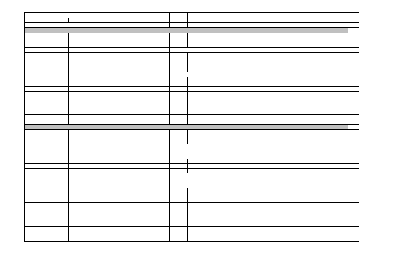
IQ 250/260 Meter App. B: Modbus Map
www.eaton.com IB02601006E MM-37
Description (Note 1) Format Range (Note 6) Units or Resolution Comments
Modbus Address
Hex Decimal #
Reg
Second Overlay write only in PS update mode
8127 - 812E 33064 - 33071 Input#1 Label ASCII 16 char 8
812F - 8136 33072 - 33079 Input#1 Low State Name ASCII 16 char 8
8137 - 813E 33080 - 33087 Input#1 High State Name ASCII 16 char 8
813F - 8156 33088 - 33111 Input#2 Label and State Names 24
8157 - 8186 33112 - 33159 Reserved 48
8187 - 818E 33160 - 33167 Relay#1 Label ASCII 16 char 8
818F - 8196 33168 - 33175 Relay#1 Open State Name ASCII 16 char 8
8197 - 819E 33176 - 33183 Relay#1 Closed State Name ASCII 16 char 8
819F - 81B6 33184 - 33207 Relay#2 Label and State Names 24
81B7 - 81E6 33208 - 33255 Reserved 48
81E7 - 81EE 33256 - 33263 Input#1 Accumulator Label ASCII 16 char 8
81EF - 81F6 33264 - 33271 Input#2 Accumulator Label ASCII 16 char 8
8208 - 8208 33289 - 33289 Input#2 Accumulator Kt UINT16 bit-mapped ddVVVVVV VVVVVVVV 1
8209 - 8326 33290 - 33575 Reserved 286
Block Size: 512
Second Overlay write only in PS update mode
8127 - 812E 33064 - 33071 Input#1 Label ASCII 16 char 8
812F - 8136 33072 - 33079 Input#1 Low State Name ASCII 16 char 8
8137 - 813E 33080 - 33087 Input#1 High State Name ASCII 16 char 8
813F - 8156 33088 - 33111 Input#2 Label and State Names 24
8157 - 816E 33112 - 33135 Input#3 Label and State Names 24
816F - 8186 33136 - 33159 Input#4 Label and State Names 24
8187 - 818E 33160 - 33167 Output#1 Label ASCII 16 char 8
818F - 8196 33168 - 33175 Output#1 Open State Name ASCII 16 char 8
8197 - 819E 33176 - 33183 Output#1 Closed State Name ASCII 16 char 8
819F - 81B6 33184 - 33207 Output#2 Label and State Names 24
81B7 - 81CE 33208 - 33231 Output#3 Label and State Names 24
81CF - 81E6 33232 - 33255 Output#4 Label and State Names 24
81E7 - 81EE 33256 - 33263 Input#1 Accumulator Label ASCII 16 char 8
81EF - 81F6 33264 - 33271 Input#2 Accumulator Label ASCII 16 char 8
81F7 - 81FE 33272 - 33279 Input#3 Accumulator Label ASCII 16 char 8
81FF - 8206 33280 - 33287 Input#4 Accumulator Label ASCII 16 char 8
8207 - 8207 33288 - 33288 Input#1 Accumulator Kt UINT16 bit-mapped ddVVVVVV VVVVVVVV 1
8208 - 8208 33289 - 33289 Input#2 Accumulator Kt UINT16 bit-mapped ddVVVVVV VVVVVVVV 1
8209 - 8209 33290 - 33290 Input#3 Accumulator Kt UINT16 bit-mapped ddVVVVVV VVVVVVVV 1
820A - 820A 33291 - 33291 Input#4 Accumulator Kt UINT16 bit-mapped ddVVVVVV VVVVVVVV 1
820B - 8326 33292 - 33575 Reserved Reserved 284
Block Size: 512
same as Input#1
same as Output#1
same as Output#1
same as Output#1
KT power factor for the accumulator input
"V" is raw power value in Wh/pulse from 0 to 9999.
"dd"=decimal point position: 00=0.XXXX, 01=X.XXX,
10=XX.XX, 11= X.XXX.
Settings Registers for Digital I/O Relay Card
same as Input#1
same as Relay#1
KT power factor for the Pulse Output
"V" is raw power value in Wh/pulse from 0 to 9999.
"dd"=decimal point position: 00=0.XXXX, 01=X.XXX,
10=XX.XX, 11= X.XXX.
Settings Registers for Digital I/O Pulse Output Card
same as Input#1
same as Input#1
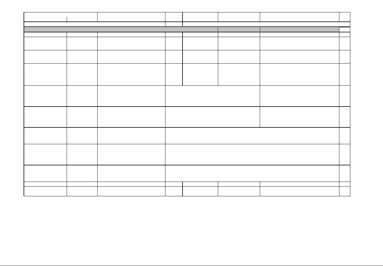
IQ 250/260 Meter App. B: Modbus Map
www.eaton.com IB02601006E MM-38
Description (Note 1) Format Range (Note 6) Units or Resolution Comments
Modbus Address
Hex Decimal #
Reg
Second Overlay write only in PS update mode
8127 - 8127 33064 - 33064 Update rate UINT16 0 to 65535 milliseconds Fixed -- see specifications. 1
8128 - 8128 33065 - 33065 Channel direction - 1mA Card only! UINT16 bit-mapped -------- ----4321 Full range output for 0-1mA card only: A bit set(1) means
full range (-1mA to +1mA); a bit cleared(0) means source
only (0mA to +1mA).
1
8129 - 8129 33066 - 33066 Format parameter for output #1 UINT16 bit-mapped -------- ---f suwb Format of the polled register:f=float 32; s=signed 32 bit
int; u=unsigned 32 bit int; w=signed 16 bit int;
b=unsigned 16 bit int.
1
812A - 812A 33067 - 33067 Source register for Output#1 UINT16 0 to 65535 This register should be programmed with the address of
the register whose value is to be used for current output.
In different words, the current level output of analog
board will follow the value of the register addressed here.
1
812B - 812C 33068 - 33069 High value of source register for output#1 Value read from the source register at which High
nominal current will be output. Example: for the 4-20mA
card, if this register is programmed with 750, then the
current output will be 20mA when the value read from the
source register is 750.
2
812D - 812E 33070 - 33071 Low value of source register for output#1 Value read from the source register at which Low
nominal current will be output. Example: for the 4-20mA
card, if this register is programmed with 0, then the
current output will be 4mA when the value read from the
source register is 0.
2
812F - 8134 33072 - 33077 Analog output#2 format, register, max & min 6
8135 - 813A 33078 - 33083 Analog output#3 format, register, max & min 6
813B - 8140 33084 - 33089 Analog output#4 format, register, max & min 6
8141 - 8326 33090 - 33575 Reserved Reserved 486
Block Size: 512
Same as analog output#1
Same as analog output#1
Same as analog output#1
Settings Registers for Analog Out 0-1mA / Analog Out 4-20mA Cards
Depends on the format parameter
Depends on the format parameter
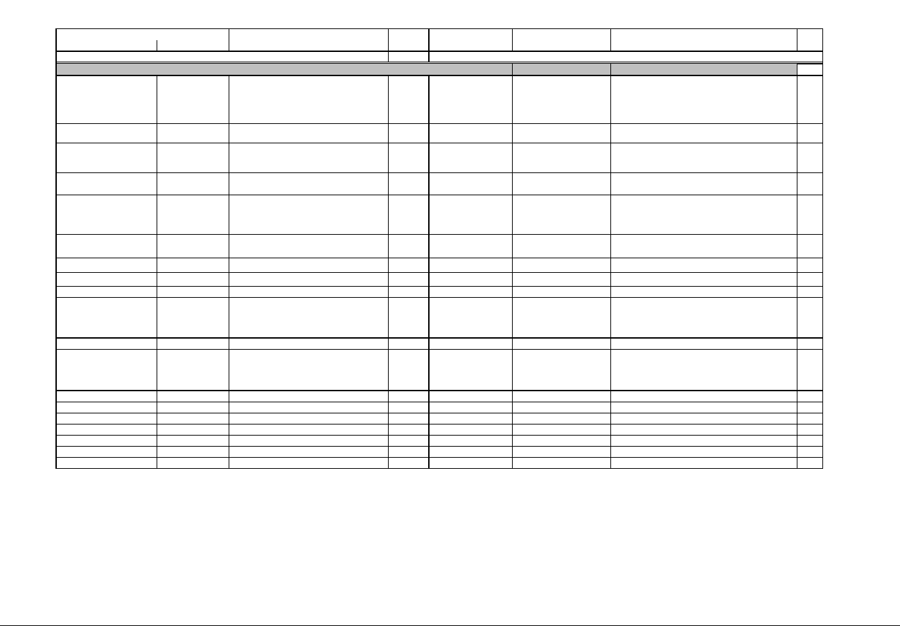
IQ 250/260 Meter App. B: Modbus Map
www.eaton.com IB02601006E MM-39
Description (Note 1) Format Range (Note 6) Units or Resolution Comments
Modbus Address
Hex Decimal #
Reg
Second Overlay write only in PS update mode
8127 - 8127 33064 - 33064 General Options bit-mapped -------- ---s cwme Servers enable(1) or disable(0) flags:
s=Modbus_TCP_server; c=Modbus_TCP_client; w=Web
server ; m=HTTP Modbus RTU for diagnostics.
Sleep enabled e=0; sleep disabled e=1.
1
8128 - 8128 33065 - 33065 DHCP enable bit-mapped -------- -------d DHCP: d=1 enabled, d=0 disabled (user must provide IP
configuration).
1
8129 - 8130 33066 - 33073 Host name label ASCII 16 bytes (8 registers) 8
8131 - 8134 33074 - 33077 IP card network address UINT16 0 to 255 (IPv4) These 4 registers hold the 4 numbers (1 number each
register) that make the IP address used by the card.
4
8135 - 8135 33078 - 33078 IP network address mask length UINT16 0 to 32 Number of bits that are set in the IP address mask,
starting from the Msb of the 32 bit word.
Example 24 = 255.255.255.0; a value of 2 would mean
192.0.0.0
1
8136 - 8139 33079 - 33082 IP card network gateway address UINT16 0 to 255 (IPv4) These 4 registers hold the 4 numbers that make the IP
gateway address on network.
4
813A - 813D 33083 - 33086 IP card network DNS #1 address UINT16 0 to 255 (IPv4) IP address of the DNS#1 on the network. 4
813E - 8141 33087 - 33090 IP card network DNS #2 address UINT16 0 to 255 (IPv4) IP address of the DNS#2 on the network. 4
8142 - 824A 33091 - 33355 Reserved Write this with 0 to keep future compatibility. 265
824B - 824B 33356 - 33356 FTP Client Flags bit-mapped -------- -----u-e General FTP flags:
u: 0=FTP remote address is an URL address; 1=FTP
remote address is an IP address.
e: 0=FTP disabled; 1=Enabled.
1
824C - 824C 33357 - 33357 Reserved Reserved 1
824D - 826C 33358 - 33389 FTP remote server address ASCII or
UINT16
The type of the data in these registers depend on bit 'u'
in the FTP Client Flags register.
IP address (4 numbers) or URL (64-characters) of the
FTP server
32
826D - 826D 33390 - 33390 FTP remote port UINT16 IP port of the remote FTP server 1
826E - 82AD 33391 - 33454 FTP remote directory ASCII 128 characters Remote directory where the files to be retrieved are. 64
82AE - 82BD 33455 - 33470 FTP remote username ASCII 32 characters Username to access remote FTP 16
82BE - 82CC 33471 - 33485 FTP remote password ASCII 32 characters Password to for previous username account. 16
82CD - 8326 33486 - 33575 Reserved Reserved 89
Block Size: 512
Settings Registers for Network Cards

IQ 250/260 Meter App. B: Modbus Map
www.eaton.com IB02601006E MM-40
Description (Note 1) Format Range (Note 6) Units or Resolution Comments
Modbus Address
Hex Decimal #
Reg
read-only except as noted
9C40 - 9C40 40001 - 40001 System Sanity Indicator UINT16 0 or 1 none 0 indicates proper meter operation 1
9C41 - 9C41 40002 - 40002 Volts A-N UINT16 2047 to 4095 volts 2047= 0, 4095= +150 1
9C42 - 9C42 40003 - 40003 Volts B-N UINT16 2047 to 4095 volts 1
9C43 - 9C43 40004 - 40004 Volts C-N UINT16 2047 to 4095 volts 1
9C44 - 9C44 40005 - 40005 Amps A UINT16 0 to 4095 amps 0= -10, 2047= 0, 4095= +10 1
9C45 - 9C45 40006 - 40006 Amps B UINT16 0 to 4095 amps 1
9C46 - 9C46 40007 - 40007 Amps C UINT16 0 to 4095 amps 1
9C47 - 9C47 40008 - 40008 Watts, 3-Ph total UINT16 0 to 4095 watts 0= -3000, 2047= 0, 4095= +3000 1
9C48 - 9C48 40009 - 40009 VARs, 3-Ph total UINT16 0 to 4095 VARs watts, VARs, VAs = 1
9C49 - 9C49 40010 - 40010 VAs, 3-Ph total UINT16 2047 to 4095 VAs 3000 * (register - 2047) / 2047 1
9C4A - 9C4A 40011 - 40011 Power Factor, 3-Ph total UINT16 1047 to 3047 none 1047= -1, 2047= 0, 3047= +1
pf = (register - 2047) / 1000
1
9C4B - 9C4B 40012 - 40012 Frequency UINT16 0 to 2730 Hz 0= 45 or less, 2047= 60, 2730= 65 or more
freq = 45 + ((register / 4095) * 30)
1
9C4C - 9C4C 40013 - 40013 Volts A-B UINT16 2047 to 4095 volts 2047= 0, 4095= +300 1
9C4D - 9C4D 40014 - 40014 Volts B-C UINT16 2047 to 4095 volts 1
9C4E - 9C4E 40015 - 40015 Volts C-A UINT16 2047 to 4095 volts 1
9C4F - 9C4F 40016 - 40016 CT numerator UINT16 1 to 9999 none 1
9C50 - 9C50 40017 - 40017 CT multiplier UINT16 1, 10, 100 none 1
9C51 - 9C51 40018 - 40018 CT denominator UINT16 1 or 5 none 1
9C52 - 9C52 40019 - 40019 PT numerator UINT16 1 to 9999 none 1
9C53 - 9C53 40020 - 40020 PT multiplier UINT16 1, 10, 100, 1000 none 1
9C54 - 9C54 40021 - 40021 PT denominator UINT16 1 to 9999 none 1
9C55 - 9C56 40022 - 40023 W-hours, Positive UINT32 0 to 99999999 Wh per energy format * 5 to 8 digits 2
9C57 - 9C58 40024 - 40025 W-hours, Negative UINT32 0 to 99999999 Wh per energy format * decimal point implied, per energy format 2
9C59 - 9C5A 40026 - 40027 VAR-hours, Positive UINT32 0 to 99999999 VARh per energy format 2
9C5B - 9C5C 40028 - 40029 VAR-hours, Negative UINT32 0 to 99999999 VARh per energy format 2
9C5D - 9C5E 40030 - 40031 VA-hours UINT32 0 to 99999999 VAh per energy format * see note 10 2
9C5F - 9C60 40032 - 40033 W-hours, Positive, Phase A UINT32 0 to 99999999 Wh per energy format 2
9C61 - 9C62 40034 - 40035 W-hours, Positive, Phase B UINT32 0 to 99999999 Wh per energy format 2
9C63 - 9C64 40036 - 40037 W-hours, Positive, Phase C UINT32 0 to 99999999 Wh per energy format 2
9C65 - 9C66 40038 - 40039 W-hours, Negative, Phase A UINT32 0 to 99999999 Wh per energy format 2
9C67 - 9C68 40040 - 40041 W-hours, Negative, Phase B UINT32 0 to 99999999 Wh per energy format 2
9C69 - 9C6A 40042 - 40043 W-hours, Negative, Phase C UINT32 0 to 99999999 Wh per energy format 2
9C6B - 9C6C 40044 - 40045 VAR-hours, Positive, Phase A UINT32 0 to 99999999 VARh per energy format 2
9C6D - 9C6E 40046 - 40047 VAR-hours, Positive, Phase B UINT32 0 to 99999999 VARh per energy format 2
9C6F - 9C70 40048 - 40049 VAR-hours, Positive, Phase C UINT32 0 to 99999999 VARh per energy format 2
9C71 - 9C72 40050 - 40051 VAR-hours, Negative, Phase A UINT32 0 to 99999999 VARh per energy format 2
9C73 - 9C74 40052 - 40053 VAR-hours, Negative, Phase B UINT32 0 to 99999999 VARh per energy format 2
9C75 - 9C76 40054 - 40055 VAR-hours, Negative, Phase C UINT32 0 to 99999999 VARh per energy format 2
9C77 - 9C78 40056 - 40057 VA-hours, Phase A UINT32 0 to 99999999 VAh per energy format 2
9C79 - 9C7A 40058 - 40059 VA-hours, Phase B UINT32 0 to 99999999 VAh per energy format 2
9C7B - 9C7C 40060 - 40061 VA-hours, Phase C UINT32 0 to 99999999 VAh per energy format 2
volts = 300 * (register - 2047) / 2047
CT = numerator * multiplier / denominator
PT = numerator * multiplier / denominator
* resolution of digit before decimal point = units, kilo, or
mega, per energy format
Secondary Readings Section
Secondary Block
volts = 150 * (register - 2047) / 2047
amps = 10 * (register - 2047) / 2047
IQ 250/260 Meter App. B: Modbus Map
www.eaton.com IB02601006E MM-41
Description (Note 1) Format Range (Note 6) Units or Resolution Comments
Modbus Address
Hex Decimal #
Reg
9C7D - 9C7D 40062 - 40062 Watts, Phase A UINT16 0 to 4095 watts 1
9C7E - 9C7E 40063 - 40063 Watts, Phase B UINT16 0 to 4095 watts 1
9C7F - 9C7F 40064 - 40064 Watts, Phase C UINT16 0 to 4095 watts 1
9C80 - 9C80 40065 - 40065 VARs, Phase A UINT16 0 to 4095 VARs 0= -3000, 2047= 0, 4095= +3000 1
9C81 - 9C81 40066 - 40066 VARs, Phase B UINT16 0 to 4095 VARs watts, VARs, VAs = 1
9C82 - 9C82 40067 - 40067 VARs, Phase C UINT16 0 to 4095 VARs 3000 * (register - 2047) / 2047 1
9C83 - 9C83 40068 - 40068 VAs, Phase A UINT16 2047 to 4095 VAs 1
9C84 - 9C84 40069 - 40069 VAs, Phase B UINT16 2047 to 4095 VAs 1
9C85 - 9C85 40070 - 40070 VAs, Phase C UINT16 2047 to 4095 VAs 1
9C86 - 9C86 40071 - 40071 Power Factor, Phase A UINT16 1047 to 3047 none 1
9C87 - 9C87 40072 - 40072 Power Factor, Phase B UINT16 1047 to 3047 none 1
9C88 - 9C88 40073 - 40073 Power Factor, Phase C UINT16 1047 to 3047 none 1
9C89 - 9CA2 40074 - 40099 Reserved N/A N/A none Reserved 26
9CA3 - 9CA3 40100 - 40100 Reset Energy Accumulators UINT16 password (Note 5) write-only register; always reads as 0 1
Block Size: 100
read/write except as noted
C34C - C34D 49997 - 49998 Log Retrieval Session Duration UINT32 0 to 4294967294 4 msec 0 if no session active; wraps around after max count 2
C34E - C34E 49999 - 49999 Log Retrieval Session Com Port UINT16 0 to 4 0 if no session active, 1-4 for session active on COM1 -
COM4
1
C34F - C34F 50000 - 50000 Log Number, Enable, Scope UINT16 bit-mapped nnnnnnnn esssssss high byte is the log number (0-system, 2-history
.
.
e is retrieval session enable(1) or disable(0)
sssssss is what to retrieve (0-normal record, 1-
timestamps only, 2-complete memory image (no data
validation if image)
1
C350 - C350 50001 - 50001 Records per Window or Batch, Record Scope
Selector, Number of Repeats
UINT16 bit-mapped wwwwwwww snnnnnnn high byte is records per window if s=0 or records per
batch if s=1, low byte is number of repeats for function
35 or 0 to suppress auto-incrementing; max number of
repeats is 8 (RTU) or 4 (ASCII) total windows, a batch is
all the windows
1
C351 - C352 50002 - 50003 Offset of First Record in Window UINT32 bit-mapped ssssssss nnnnnnnn
nnnnnnnn nnnnnnnn
ssssssss is window status (0 to 7-window number, 0xFF-
not ready); this byte is read-only.
nn…nn is a 24-bit record number. The log's first record
is latched as a reference point when the session is
enabled. This offset is a record index relative to that
point. Value provided is the relative index of the whole or
partial record that begins the window.
2
C353 - C3CD 50004 - 50126 Log Retrieve Window UINT16 see comments none mapped per record layout and retrieval scope, read-only 123
Block Size: 130
1047= -1, 2047= 0, 3047= +1
pf = (register - 2047) / 1000
Log Retrieval Section
Log Retrieval Block
IQ 250/260 Meter App. B: Modbus Map
www.eaton.com IB02601006E MM-42
Description (Note 1) Format Range (Note 6) Units or Resolution Comments
Modbus Address
Hex Decimal #
Reg
read only
C738 - C747 51000 - 51015 Reserved 16
C748 - C749 51016 - 51017 System Log Log Size in Records UNIT32 0 to 4,294,967,294 record 2
C74a - C74b 51018 - 51019 Number of Records Used UNIT32 1 to 4,294,967,294 record 2
C74c - C74c 51020 - 51020 Record Size in Bytes UNIT16 14 to 242 byte 1
C74d- C74d 51021 - 51021 Log Availability UNIT16 none 0=unavailable 1
C74e - C750 51022 - 51024 Timestamp, First Record TSTAMP Jan2000 - 31Dec2099 1 sec 3
C751 - C753 51025 - 51027 Timestamp, Last Record TSTAMP Jan2000-31Dec2099 1 sec .. 3
.
C754 - C757 51028 - 51031 Reserved
C758 - C767 51032 - 51047 Historical Log Status 16
C768 - C7b7 51048 - 51127 Reserved
Block Size: 128
.
.
.
.
. 4
same as system log block
End of Map

IQ 250/260 Meter App. B: Modbus Map
www.eaton.com IB02601006E MM-43
Notes
1
2
3
4
5
6
7
8
9
10
11
12
FS = CT numerator * CT multiplier
FS = PT numerator * PT multiplier
FS = 60 (or 50)
FS = 1.0
FS = 100.0
FS = 180.0
13
14
15
16
17
18
Limits evaluation for all entites except demand averages commences immediately after the warmup period. Evaluation for demand averages, maximum demands, and minimum demands commences at the end of the
first demand interval after startup.
Not applicable to IQ 250/260 meters.
frequency
power factor
percentage
angle
THD not available shows 10000 in all THD and harmonic magnitude and phase registers for the channel. THD may be unavailable due to low V or I amplitude, delta hookup (V only), or meter model.
Option Card Identification and Configuration Block is an image of the EEPROM on the card.
A block of data and control registers is allocated for each option slot. Interpretation of the register data depends on what card is in the slot.
Measurement states: Off occurs during programmable settings updates; Run is the normal measuring state; Limp indicates that an essentail non-volatile memory block is corrupted; and Warmup occurs briefly
(approximately 4 seconds) at startup while the readings stabilize. Run state is required for measurement, historical logging, demand interval processing, limit alarm evaluation, min/max comparisons, and THD
calculations. Resetting min/max or energy is allowed only in run and off states; warmup will return a busy exception. In limp state, the meter reboots at 5 minute intervals in an effort to clear the problem.
Entities to be monitored against limits are identified by Modbus address. Entities occupying multiple Modbus registers, such as floating point values, are identified by the lower register address. If any of the 8 limits is
unused, set its identifier to zero. If the indicated Modbus register is not used or is a nonsensical entity for limits, it will behave as an unused limit.
There are 2 setpoints per limit, one above and one below the expected range of values. LM1 is the "too high" limit, LM2 is "too low". The entity goes "out of limit" on LM1 when its value is greater than the setpoint. It
remains "out of limit" until the value drops below the in threshold. LM2 works similarly, in the opposite direction. If limits in only one direction are of interest, set the in threshold on the "wrong" side of the setpoint.
Limits are specified as % of full scale, where full scale is automatically set appropriately for the entity being monitored:
current
voltage
3 phase power FS = CT numerator * CT multiplier * PT numerator * PT multiplier * 3 [ * SQRT(3) for delta hookup]
single phase power FS = CT numerator * CT multiplier * PT numerator * PT multiplier [ * SQRT(3) for delta hookup]
Register valid only in programmable settings update mode. In other modes these registers read as 0 and return an illegal data address exception if a write is attempted.
Meter command registers always read as 0. They may be written only when the meter is in a suitable mode. The registers return an illegal data address exception if a write is attempted in an incorrect mode.
If the password is incorrect, a valid response is returned but the command is not executed. Use 5555 for the password if passwords are disabled in the programmable settings.
M denotes a 1,000,000 multiplier.
Each identifier is a Modbus register. For entities that occupy multiple registers (FLOAT, SINT32, etc.) all registers making up the entity must be listed, in ascending order. For example, to log phase A volts, VAs,
voltage THD, and VA hours, the register list would be 0x3E7, 0x3E8, 0x411, 0x412, 0x176F, 0x61D, 0x61E and the number of registers (0x7917 high byte) would be 7.
Writing this register causes data to be saved permanently in nonvolatile memory. Reply to the command indicates that it was accepted but not whether or not the save was successful. This can only be determined
after the meter has restarted.
Reset commands make no sense if the meter state is LIMP. An illegal function exception will be returned.
Energy registers should be reset after a format change.
FLOAT 32-bit IEEE floating point number spanning 2 registers. The lower-addressed register is the high order half (i.e., contains the exponent).
TSTAMP 3 adjacent registers, 2 bytes each. First (lowest-addressed) register high byte is year (0-99), low byte is month (1-12). Middle register high byte is day(1-31), low byte is hour (0-23 plus DST bit).
DST (daylight saving time) bit is bit 6 (0x40). Third register high byte is minutes (0-59), low byte is seconds (0-59). For example, 9:35:07AM on October 12, 2049 would be 0x310A, 0x0C49,
0x2307, assuming DST is in effect.
All registers not explicitly listed in the table read as 0. Writes to these registers will be accepted but won't actually change the register (since it doesn't exist).
Meter Data Section items read as 0 until first readings are available or if the meter is not in operating mode. Writes to these registers will be accepted but won't actually change the register.
Data Formats
ASCII ASCII characters packed 2 per register in high, low order and without any termination characters.
SINT16 / UINT16 16-bit signed / unsigned integer.
SINT32 / UINT32 32-bit signed / unsigned integer spanning 2 registers. The lower-addressed register is the high order half.

IQ 250/260 Meter App. B: Modbus Map
www.eaton.com IB02601006E MM-44
19
20
21
22
Depending on the meter model, there are 15, 29, or 45 flash sectors available in a common pool for distribution among the historical and waveform logs. The pool size, number of sectors for each log, and the number
of registers per record together determine the maximum number of records a log can hold.
S = number of sectors assigned to the log,
H = number of Modbus registers to be monitored in each historical record (up to 117),
R = number of bytes per record = (12 + 2H) for historical logs
N = number of records per sector = 65516 / R, rounded down to an integer value (no partial records in a sector)
T = total number of records the log can hold = S * N
.
Only 1 input on all digital input cards may be specified as the end-of-interval pulse.
Logs cannot be reset during log retrieval. Busy exception will be returned.
Combination of class and type currently defined are:
0x23 = Fiber cards
0x24 = Network card
0x41 = Relay card
0x42 = Pulse card
0x81 = 0-1mA analog output card
0x82 = 4-20mA analog output card.
Appendix C:
IQ 250/260 Meter Using DNP Mapping for IQ 250/260
www.eaton.com IB02601006E C-1
App.C Using DNP Mapping for IQ 250/260
Overview
This Appendix describes the functionality of the IQ 250/260 meter's version of the DNP protocol. A DNP
programmer needs this information to retrieve data from the meter. The DNP version used by the IQ
250/260 is a reduced set of the Distributed Network Protocol Version 3.0 subset 2; it gives enough
functionality to get critical measurements from the meter.
This DNP version supports Class 0 object/qualifiers 0,1,2,6, only. No event generation is supported. The
IQ 250/260 meter always acts as a secondary device (slave) in DNP communication.
Physical Layer
The IQ 250/260 meter’s DNP version uses serial communication. It can be assigned to Port 2 (RS485
compliant port) or any communication capable option board. Speed and data format is transparent: they
can be set to any supported value.
Data Link Layer
The IQ 250/260 can be assigned with a value from 1 to 65534 as the target device address for. The data
link layer follows the standard frame FT3 used by the DNP Version 3.0 protocol, but only 4 functions are
implemented: Reset Link, Reset User, Unconfirmed User Data, and Link Status, as depicted in following
table.
Function Function Code
Reset Link 0
Reset User 1
Unconfirmed User Data 4
Link Status 9
Table C.1: Supported Link Functions
.[dst] and [src] are the device address of the IQ 250/260 and Master device, respectively.
In order to establish optimal communication with the meter, we recommend that you perform the Reset
Link and Reset User functions. The Link Status is not mandatory, but can be performed as well. The inter-
character time-out for DNP is 1 second. If this amount of time, or more, elapses between two consecutive
characters within a FT3 frame, the frame will be dropped.
The inter-character time-out for DNP Lite is 1 second. If this amount of time, or more, elapses between
two consecutive characters within a FT3 frame, the frame will be dropped.

Appendix C:
Using DNP Mapping for IQ 250/260 IQ 250/260 Meter
C-2 IB02601006E www.eaton.com
Application Layer
The IQ 250/260 meter’s DNP version supports the Read function, Write Function, the Direct Operate
function and the Direct Operate Unconfirmed function.
The Read function (code 01) provides a means for reading the critical measurement data from
the IQ 250/260 meter. This function should be posted to read object 60 variation 1, which will
read all the available Class 0 objects from the DNP register map. See register map in following
section. In order to retrieve all objects with their respective variations, the qualifier must be set to
ALL (0x06). See the DNP Message Layouts for an example showing a read Class 0 request data
from the IQ 250/260.
The Write function (code 02) provides a mean for clearing the Device restart bit in the Internal
Indicator register only. This is mapped to Object 80, point 0 with variation 1. When clearing the
restart device indicator use qualifier 0. The DNP Message Layouts section shows the supported
frames for this function.
The Direct Operate function (code 05) is intended for resetting the energy counters and the
demand counters (minimum and maximum energy registers). These actions are mapped to
Object 12, point 0 and point 2, that are seen as a control relay.
The relay must be operated (On) in 0 msec and released (Off) in 1 msec only. Qualifiers 0x17 or
x28 are supported for writing the energy reset. Sample frames are shown in the DNP Message
Layouts section.
The Direct Operate Unconfirmed (or Unacknowledged) function (code 06) is intended for
asking the communication port to switch to Modbus RTU protocol from DNP Lite. This switching
is seen as a control relay mapped into Object 12, point 1 in the IQ 250/260. The relay must be
operated with qualifier 0x17, code 3 count 0, with 0 millisecond on and 1 millisecond off, only.
After sending this request the current communication port will accept Modbus RTU frames only.
To make this port go back to DNP protocol, the unit must be power-recycled. The DNP Message
Layouts section shows the constructed frame to perform DNP to Modbus RTU protocol change.
Error Reply
In the case of an unsupported function, or any other recognizable error, an error reply will be generated
from the IQ 250/260 to the Primary station (the requester). The Internal Indicator field will report the type
of error: unsupported function or bad parameter.
The broadcast acknowledge and restart bit, are also signaled in the internal indicator but they do not
indicate an error condition.

Appendix C:
IQ 250/260 Meter Using DNP Mapping for IQ 250/260
www.eaton.com IB02601006E C-3
DNP Register Map
Object 10 – Binary Output States
Object Point Var Description Format Range Multiplier Units Comments
10 0 2 Reset Energy
Counters BYTE Always 1 N/A None Read by Class 0 or with
qualifier 0, 1, 2 or 6
10 1 2 Change to Modbus
RTU Protocol BYTE Always 1 N/A None Read by Class 0 or with
qualifier 0, 1, 2 or 6
10 2 2 Reset Demand
Cntrs (Max / Min ) BYTE Always 1 N/A None Read by Class 0 or with
qualifier 0, 1, 2 or 6
Object 12 – Control Relay Outputs
Object Point Var Description Format Range Multiplier Units Comments
12 0 1 Reset Energy
Counters N/A N/A N/A none Responds to Function 5
(Direct Operate), Qualifier
Code 17x or 28x, Control
Code 3, Count 0, On 0 msec,
Off 1 msec ONLY.
12 1 1 Change to
Modbus RTU
Protocol
N/A N/A N/A none Responds to Function 6
(Direct Operate - No Ack),
Qualifier Code 17x, Control
Code 3, Count 0, On 0 msec,
Off 1 msec ONLY.
12 2 1 Reset Demand
Counters (Max /
Min)
N/A N/A N/A none Responds to Function 5
(Direct Operate), Qualifier
Code 17x or 28x, Control
Code 3, Count 0, On 0 msec,
Off 1 msec ONLY.
Object 20 – Binary Counters (Primary Readings) - Read via Class 0 or with qualifier 0, 1, 2, or 6
Object Point Var Description Format Range Multiplier Units Comments
20 0 5 W-hours,
Positive UINT32 0 to
99999999 Multiplier = 10(n-d),
where n and d are
derived from the
energy format. n =
0, 3, or 6 per
energy format scale
and d = number of
decimal places.
W hr example:
energy format = 7.2K and W-
hours counter = 1234567 n=3
(K scale), d=2 ( 2 digits after
decimal point), multiplier =
10(3-2) = 101 = 10, so energy
is 1234567 * 10 Whrs, or
12345.67 KWhrs
20 1 5 W-hours,
Negative UINT32 0 to
99999999 W hr
20 2 5 VAR-hours,
Positive UINT32 0 to
99999999 VAR
hr
20 3 5 VAR-hours,
Negative UINT32 0 to
99999999 VAR
hr
20 4 5 VA-hours, Total UINT32 0 to
99999999 VA hr

Appendix C:
Using DNP Mapping for IQ 250/260 IQ 250/260 Meter
C-4 IB02601006E www.eaton.com
Object 30 – Analog Inputs (Secondary Readings) - Read via Class 0 or with qualifier 0, 1, 2, or 6
Object Point Var Description Format Range Multiplier Units Comments
30 0 4 Meter Health sint16 0 or 1 N/A None 0 = OK
30 1 4 Volts A-N sint16 0 to 32767 (150 / 32768) V Values above 150V
secondary read 32767.
30 2 4 Volts B-N sint16 0 to 32767 (150 / 32768) V
30 3 4 Volts C-N sint16 0 to 32767 (150 / 32768) V
30 4 4 Volts A-B sint16 0 to 32767 (300 / 32768) V Values above 300V
secondary read 32767.
30 5 4 Volts B-C sint16 0 to 32767 (300 / 32768) V
30 6 4 Volts C-A sint16 0 to 32767 (300 / 32768) V
30 7 4 Amps A sint16 0 to 32767 (10 / 32768) A Values above 10A
secondary read 32767.
30 8 4 Amps B sint16 0 to 32767 (10 / 32768) A
30 9 4 Amps C sint16 0 to 32767 (10 / 32768) A
30 10 4 Watts, 3-Ph total sint16 -32768 to
+32767
(4500 / 32768) W
30 11 4 VARs, 3-Ph total sint16 -32768 to
+32767
(4500 / 32768) VAR
30 12 4 VAs, 3-Ph total sint16 0 to +32767 (4500 / 32768) VA
30 13 4 Power Factor, 3-Ph total sint16 -1000 to +1000 0.001 None
30 14 4 Frequency sint16 0 to 9999 0.01 Hz
30 15 4 Positive Watts, 3-Ph,
Maximum Avg Demand
sint16 -32768 to
+32767
(4500 / 32768) W
30 16 4 Positive VARs, 3-Ph,
Maximum Avg Demand
sint16 -32768 to
+32767
(4500 / 32768) VAR
30 17 4 Negative Watts, 3-Ph,
Maximum Avg Demand
sint16 -32768 to
+32767
(4500 / 32768) W
30 18 4 Negative VARs, 3-Ph,
Maximum Avg Demand
sint16 -32768 to
+32767
(4500 / 32768) VAR
30 19 4 VAs, 3-Ph, Maximum Avg
Demand
sint16 -32768 to
+32767
(4500 / 32768) VA
30 20 4 Angle, Phase A Current sint16 -1800 to +1800 0.1 degree
30 21 4 Angle, Phase B Current sint16 -1800 to +1800 0.1 degree
30 22 4 Angle, Phase C Current sint16 -1800 to +1800 0.1 degree
30 23 4 Angle, Volts A-B sint16 -1800 to +1800 0.1 degree
30 24 4 Angle, Volts B-C sint16 -1800 to +1800 0.1 degree
30 25 4 Angle, Volts C-A sint16 -1800 to +1800 0.1 degree
30 26 4 CT numerator sint16 1 to 9999 N/A none CT ratio =
30 27 4 CT multiplier sint16 1, 10, or 100 N/A none (numerator * multiplier) /
denominator
30 28 4 CT denominator sint16 1 or 5 N/A none
30 29 4 PT numerator SINT16 1 to 9999 N/A none PT ratio =
30 30 4 PT multiplier SINT16 1, 10, or 100 N/A none (numerator * multiplier) /
denominator
30 31 4 PT denominator SINT16 1 to 9999 N/A none
30 32 4 Neutral Current SINT16 0 to 32767 (10 / 32768) A For 1A model, multiplier is
(2 / 32768) and values
above 2A secondary read
32767
.
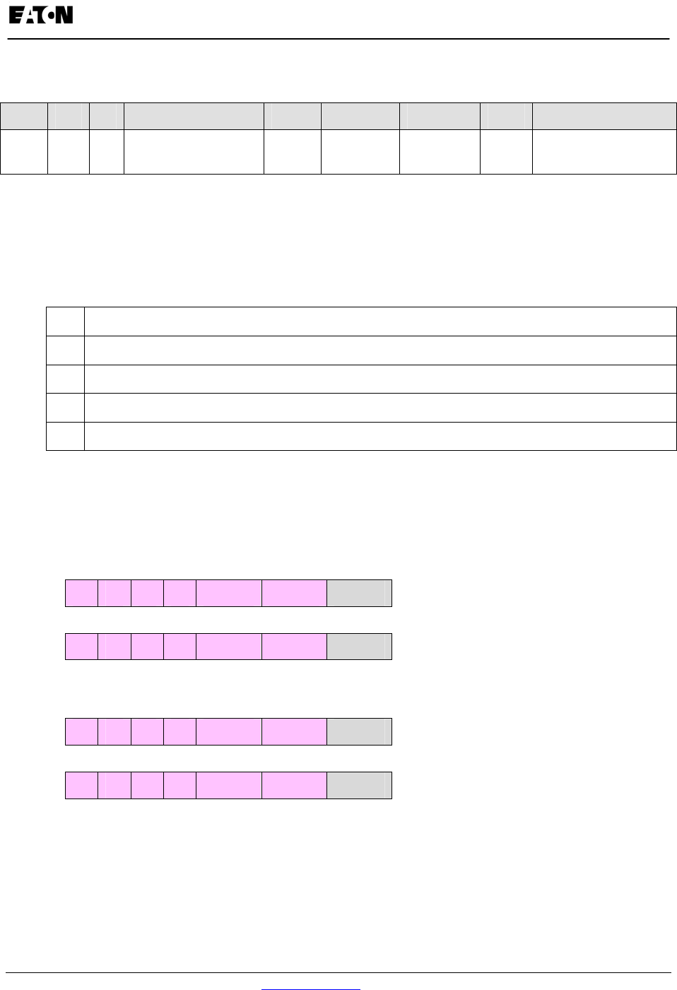
Appendix C:
IQ 250/260 Meter Using DNP Mapping for IQ 250/260
www.eaton.com IB02601006E C-5
Object 80 – Internal Indicator
Object Point Var Description Format Range Multiplier Units Comments
80 0 1 Device Restart Bit N/A N/A N/A none Clear via Function 2
(Write), Qualifier Code 0.
DNP Message Layouts
Legend
All numbers are in hexadecimal base. In addition the following symbols are used.
dst 16 bit frame destination address
src 16 bit frame source address
crc DNP Cyclic redundant checksum (polynomial x16+x13+x12+x11+x10+x7+x6+x5+x2+1)
x transport layer data sequence number
y application layer data sequence number
Link Layer related frames
Reset Link
Request 05 64 05 C0 dst src crc
Reply 05 64 05 00 src dst crc
Reset User
Request 05 64 05 C1 dst src crc
Reply 05 64 05 00 src dst crc
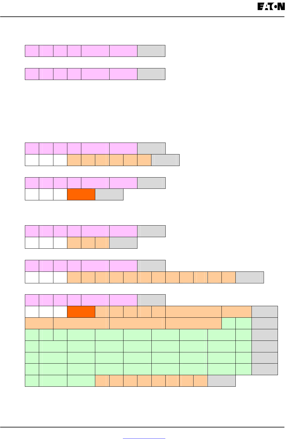
Appendix C:
Using DNP Mapping for IQ 250/260 IQ 250/260 Meter
C-6 IB02601006E www.eaton.com
Link Status
Request 05 64 05 C9 dst src crc
Reply 05 64 05 0B src dst crc
Application Layer related frames
Clear Restart
Request 05 64 0E C4 dst src crc
Cx Cy 02 50 01 00 07 07 00 crc
Reply 05 64 0A 44 src dst crc
Cx Cy 81 int. ind. crc
Class 0 Data
Request 05 64 0B C4 dst src crc
Cx Cy 01 3C 01 06 crc
Request 05 64 14 C4 dst src crc
(alternate) Cx Cy 01 3C 02 06 3C 03 06 3C 04 06 3C 01 06 crc
Reply 05 64 72 44 src dst crc
Cx Cy 81 int. ind. 14 05 00 00 04 pt 0 pt 1 crc
pt 1 pt 2 pt 3 pt 4 1E 04 crc
(same for
either
request)
00 00 20 pt 0 pt 1 pt 2 pt 3 pt 4 pt 5 pt6 crc
pt6 pt 7 pt 8 pt 9 pt 10 pt 11 pt 12 pt 13 crc
pt 15 pt 16 pt 17 pt 18 pt 19 pt 20 pt 21 crc
pt 23 pt 24 pt 25 pt 26 pt 27 pt 28 pt 29 crc
pt 31 pt 32 0A 02 00 00 02 pt0 pt1 pt2 crc
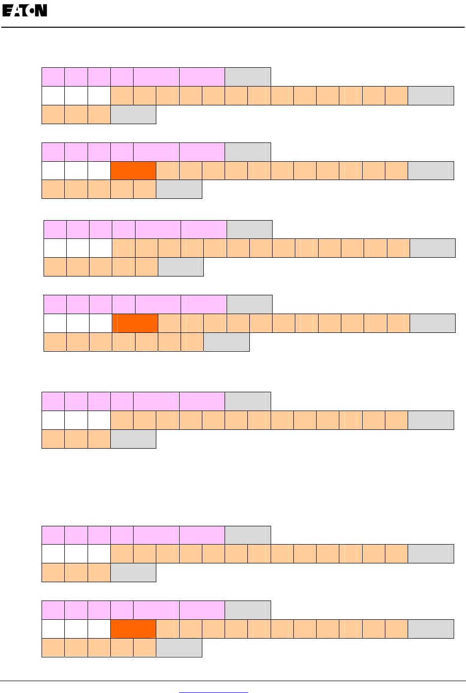
Appendix C:
IQ 250/260 Meter Using DNP Mapping for IQ 250/260
www.eaton.com IB02601006E C-7
Reset Energy
Request 05 64 18 C4 dst src crc
Cx Cy 05 0C 01 17 01 00 03 00 00 00 00 00 01 00 crc
00 00 00 crc
Reply 05 64 1A 44 src dst crc
Cx Cy 81 int. ind. 0C 01 17 01 00 03 00 00 00 00 00 crc
01 00 00 00 00 crc
Request 05 64 1A C4 dst src crc
(alternate) Cx Cy 05 0C 01 28 01 00 00 00 03 00 00 00 00 00 crc
01 00 00 00 00 crc
Reply 05 64 1C 44 src dst crc
Cx Cy 81 int. ind. 0C 01 28 01 00 00 00 03 00 00 00 crc
00 00 01 00 00 00 00 crc
Switch to Modbus
Request 05 64 18 C4 dst src crc
Cx Cy 06 0C 01 17 01 01 03 00 00 00 00 00 01 00 crc
00 00 00 crc
No Reply
Reset Demand (Maximums & Minimums)
Request 05 64 18 C4 dst src crc
Cx Cy 05 0C 01 17 01 02 03 00 00 00 00 00 01 00 crc
00 00 00 crc
Reply 05 64 1A 44 src dst crc
Cx Cy 81 int. ind. 0C 01 17 01 02 03 00 00 00 00 00 crc
01 00 00 00 00 crc
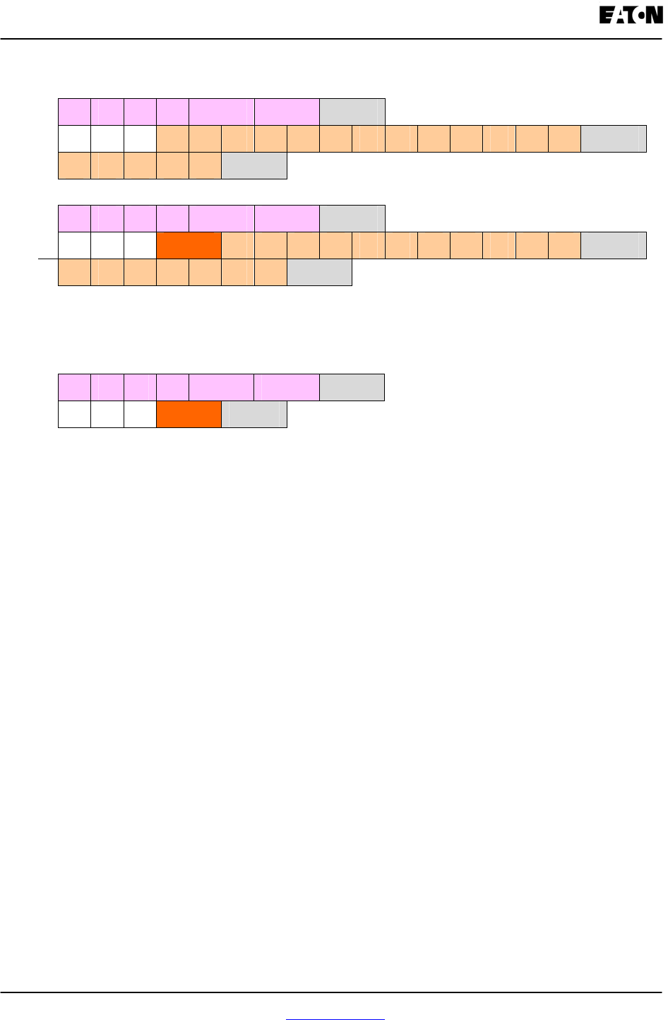
Appendix C:
Using DNP Mapping for IQ 250/260 IQ 250/260 Meter
C-8 IB02601006E www.eaton.com
Request 05 64 1A C4 dst src crc
(alternate) Cx Cy 05 0C 01 28 01 02 00 00 03 00 00 00 00 00 crc
01 00 00 00 00 crc
Reply 05 64 1C 44 src dst crc
Cx Cy 81 int. ind. 0C 01 28 01 02 00 00 03 00 00 00 crc
00 00 01 00 00 00 00 crc
Error Reply
Reply 05 64 0A 44 src dst crc
Cx Cy 81 int. ind. crc
Internal Indication Bits
Bits implemented in the IQ 250/260 meter are listed below. All others are always reported as zeroes.
Bad Function
Occurs if the function code in a User Data request is not Read (0x01), Write (0x02), Direct Operate
(0x05), or Direct Operate, No Ack (0x06).
Object Unknown
Occurs if an unsupported object is specified for the Read function. Only objects 10, 20, 30, and 60 are
supported.
Out of Range
Occurs for most other errors in a request, such as requesting points that don’t exist or direct operate
requests in unsupported formats.
Buffer Overflow
Occurs if a read request or a read response is too large for its respective buffer. In general, if the request
overflows, there will be no data in the response while if the response overflows at least the first object will
be returned. The largest acceptable request has a length field of 26, i.e. link header plus 21 bytes more,
not counting checksums. The largest possible response has 7 blocks plus the link header.
Restart
All Stations
These 2 bits are reported in accordance with standard practice.
